1
Issued under the authority of the Home Office
(Fire and Emergency Planning Directorate)
Fire Service Manual
Volume 1
Fire Service Technology,
Equipment and Media
Communications
and
Mobilising
HM Fire Service Inspectorate Publications Section
London: The Stationery Office
© Crown Copyright 1998
Published with the permission of the Home Office
on behalf of the Controller of Her Majesty's Stationery Office
Applications for reproduction should be made in
writing to The Copyright Unit, Her Majesty's Stationery Office,
St. Clements House, 2-16 Colegate, Norwich, NR3 1BQ
ISBNO 11 3411855
Cover photographs:
Upper: Surrey Fire and Rescue Service
Lower: London Fire Brigade
Half-title page photograph:
Hertfordshire Fire and Rescue Service
Printed in the United Kingdom for The Stationery Office
J50973 7/98 C50 5673
Communications
and Mobilising
Preface
The first edition Part 5 of the Manual of
Firemanship dealing with the subject of communications was issued in 1954. It concluded "Fire
Service communications are intimately related to
an intricate field of electrical engineering, which
includes telecommunications both by landline and
wireless, which is in turn only a small part of the
territory covered by electrical science".
The passage of time and advances in technology
have changed every concept of fire service communications from those identified by the writers
within the first edition of Part 5. The basic fire services' communications requirements have, however, remained unchanged and are identified in the
1947 Fire Services Act. This is still as relevant
today as it was when first mandated to fire authorities in 1947, to "secure efficient arrangements for
dealing with calls for the assistance of the fire
brigade in case of fire and for summoning members".
which may be available in the future. This book is
written in non-technical terms and aimed primarily at covering the operational and functional communications requirements of the professional firefighter. This, by necessity, encompasses all the
communicating elements from that of "the originating caller to the incident's conclusion" via the
brigade Control, station call-out and Incident
Command structures. The text, diagrams and symbols used, whilst not necessarily conforming to
those in other technical publications, have been
modified as appropriate to assist the reader. Those
who require further technical detail must refer to
other publications and technical sources which
specialise in the area concerned.
To ensure that fire services' communications efficiency is maintained to the highest level requires
the introduction of modern technology systems,
coupled with frequent reviews to brigades' practises and procedures. Changes in equipment and
procedures become inevitable, because either
equipment becomes obsolete, or technical maintenance support is exhausted or overly expensive.
New equipment often has advantages over what it
replaces, in that it generally incorporates more
functionality and flexibility, thus affording
greater opportunities for changes in procedures
and practises.
It is anticipated that this book will be invaluable to
brigade Communications Officers and all personnel who are or become intimately involved in the
planning, procurement, implementation and operation of mobilising systems, communications systems, radio and fixed and mobile communications.
As in Book 10 of the Manual of Firemanship, a
great deal of emphasis has been placed upon planning principles, and the importance of clearly identifying both the operational requirements and the
constraints associated with procurement processes.
New technology solutions can be both implemented and beneficial if, as a result of a due planning
process, they address and meet the needs and criteria of 'the user'. New technology should not,
however, be seen as the driving force and the reason to change for changes sake. This is especially
so in areas where an overall simpler solution could
be adopted instead.
It is an impossible task to bring the reader fully upto-date with the technology that is both available
and continually evolving, or indeed to indicate that
It is hoped that the information and advice contained within this book will help to ensure that the
Fire Services' Communications and associated
Communications and Mobilising
iii
systems will at least maintain and ideally improve
their present standards of efficiency and reliability.
The Home Office is greatly indebted to all those
who have contributed and assisted (by providing
material and information) in the preparation of the
edition.
This book replaces the Manual of Firemanship
Book 10 Fire Brigade Communications and
Mobilising.
Home Office
June 1998
iv
Fire Service Manual
Communications
and Mobilising
Contents
Preface
Hi
Chapter 1 Regulatory issues
1
1.1
1.2
1.3
1.4
2
2
3
8
H.M. Government
OFTEL
Radio Frequency Management
Home Office Communications Advisory Panel (HOCAP)
Chapter 2 Fire Control Centres
11
2.1
Basic Call Handling Procedures
11
2.2
Control Centre Staffing Levels
15
Chapter 3 A brief history of the 'Fire Control Centre'
17
Chapter 4 The 999/112 emergency service
23
4.1
4.1.1
4.1.2
4.1.3
4.1.4
4.1.5
4.1.6
4.1.7
4.1.8
4.1.9
4.1.10
4.1.11
4.1.12
4.2
4.2.1
4.2.2
4.3
4.4
4.5
4.6
4.6.1
4.7
4.8
4.8.1
4.8.2
4.8.3
23
23
24
26
26
26
27
28
28
28
29
30
30
30
31
32
32
33
33
34
35
35
35
36
36
37
BT
The British Telecom fixed telephone system
Operator call-handling procedures
Mismatches between EA and Fixed Network Operator Boundaries
Provision of ex-directory information
Access to tape recordings of Emergency Calls
Calling Line Identity (CLI)
Network Resilience
Priority Fault Repair Service
BT National Emergency Linkline
Government Telephone Preference Scheme
Secondary Control
Publicity/Public Education
Cable & Wireless 999 service
Operator call-handling procedure
Enquiries and requests from emergency services
Kingston Communications
Telephone Number Portability
Emergency Text Telephone Service for the deaf
Emergency calls from the Railway Industry Network
Paypnones
Cellular communications
Cellular 999 services
Name and Address Information of Mobile Callers
Release of Subscriber information
System Description - ORANGE
Communications and Mobilising
V
4.8.4
Cell/EA Boundaries
4.8.5
Routing 999/112 Calls to EACCs
4.8.6
Cell ID Look-Up Failure
4.8.7
EACC Connect-to Numbers
4.8.8
Misrouted Calls
4.9
The satellite telephone
4.10 Public Warning and Information by Telephone (PWIT)
4.10.1
How the proposed BT 'PWIT' system would work
Chapter 5
5.1
5.2
5.2.1
5.2.2
5.2.3
5.2.4
5.2.5
5.2.6
5.2.7
5.2.8
5.2.9
5.3
5.3.1
5.4
5.4.1
5.4.2
5.4.3
5.4.4
5.4.5
5.4.6
5.4.7
5.5
5.5.1
5.5.2
5.5.3
5.5.4
5.5.5
5.5.6
5.5.7
5.5.8
5.5.9
5.5.10
5.5.11
5.5.12
Control Centre equipment
Control Centre Design
Communications
Administrative Communications
Safeguards for Emergency Communications
Provision of Suitable Circuits
Alternative Routing of Cables
Monitoring of Remote Circuits
Exchange Telephone Lines
Operational Lines
Line Concentrator Units and Digital Switches
Automatic Call Distribution
Computerising Mobilising System
Mobilising System Functions
Ancillary Control Facilities
Voice Recorders
Availability and Fire Situation Display
The Gazetteer
Maps
Automatic Fire Alarm (AFA) Terminations
Secondary Control Facilities
Control Centre Software
Equipment at Fire Stations
Mobilising Computer
Printers
Alerter Base Station
Public Address System
Turnout Lighting
Alternative Power Supply
Exhaust Extraction Systems
Control of Traffic Signals
Automatic Appliance Room Door
Running Call Facilities
Enquiry Bell
Other Ancillary Equipment
C h a p t e r 6 A u t o m a t i c Fire A l a r m T r a n s m i s s i o n S y s t e m s
6.1
6.2
vi
Transmission Methods and Reliability Issues
Social and Community Alarms Centres
Fire Service Manual
37
37
38
38
38
39
39
40
43
44
44
44
44
45
45
45
46
46
46
48
48
48
51
51
52
52
53
53
54
54
54
54
54
54
54
55
55
55
55
56
56
56
56
57
57
60
Chapter 7 Automatic Vehicle Location Systems
7.1
7.2
7.3
7.4
7.5
7.6
63
AVLS Technology
Potential Benefits of AVLS to the Fire Service
AVLS System Implementation
Operational Considerations
Implementation Costs
Conclusions
64
66
66
67
67
68
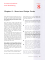
Chapter 8 Smart and Swipe Cards
69
Chapter 9 CCTV in the Fire Service
71
Chapter 10 Radio
75
10.1 Frequency Spectrum characteristics, selection and allocation
10.1.1
The Frequency Spectrum
10.1.2
Characteristics of the different Frequency Bands
10.1.3
Frequency Selection and Allocation
10.1.4
Channel Spacing
10.2 Radio Scheme Engineering
10.2.1
Modulation methods
10.2.2
Talk-through
10.2.3
Wide Area Coverage
10.2.4
The Spaced Carrier System
10.2.5
The 'Quasi-Synchronous' or 'Common Frequency' System
10.2.6
Scheme Engineering
10.2.7
Links
10.2.8
Frequencies
10.2.9
Equipment
10.2.10 Fixed Mobiles
10.2.11 Main Control
10.2.12 Transportable Equipment
10.2.13 Power Supply Arrangements
10.2.14 Microwave
10.2.15 Multiplexing
10.3 Mobile, Transportable and Personal Radio Equipment
10.3.1
Conventions
10.3.2
Mobile Equipment
10.3.3
The Aerial
10.3.4
Channel Selection
10.3.5
Squelch
10.3.6
Transmission Timer
10.3.7
Power Supplies
10.3.8
Fixed Mobile Version
10.3.9
Special Features
10.3.10 Transportable Equipment
10.3.11 Personal Equipment
10.3.12 Methods of using Personal Radios
10.3.13 Composite Units
10.3.14 Personal Hand-Held Radio Sets
10.3.15 Intrinsically Safe Personal Radios
Communications and Mobilising
75
75
77
78
79
79
79
81
82
82
82
83
83
84
85
86
86
87
87
87
88
89
89
89
90
90
90
90
91
91
91
92
93
93
95
96
96
vii
10.3.16 B.A. Radio Communications Interfaces
10.3.17 Disadvantages of use of radio with B.A.
10.3.18 User Discipline
10.3.19 Security
10.3.20 Care of Hand-Held Radio Equipment
10.4 Trunked mobile radio systems
96
96
96
97
97
98
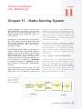
Chapter 11 Radio Alerting System
99
11.1
11.2
11.3
11.4
99
100
101
101
Alerter - General Description
Encoder
Transmitter
Alerters
Chapter 12 Mobile Data
12.1
12.2
12.3
12.4
12.5
12.6
12.7
What is Data?
History
Current Technology
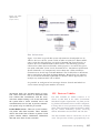
Radio Communications
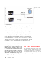
Data on Vehicles
Typical Data Requirements
Mobile Control Units
103
103
103
104
104
105
106
108
Chapter 13 Breathing Apparatus Telemetry
109
Chapter 14 Sub-surface communications
113
Chapter 15 Potential hazards of using radio equipment
115
15.1
15.2
15.3
15.4
15.5
15.6
15.7
15.8.
15.9
Explosion Protection - Standards
Ignition Sources
Protective Measures
Intrinsically Safe Design Criteria
Selection of Explosion Protected Equipment
Radio Use in the Vicinity of Explosives, etc.
Radio Use in the Vicinity of Retail Petrol Stations, etc.
Radio Use in the Vicinity of Air Bags
Radio Use in the Vicinity of Medical Devices
15.10 Radio Use within Silos
115
116
116
117
117
118
118
118
118
119
Glossary of terms and abbreviations
121
Appendix 1: Control Staff- Training, Competence and Promotion
127
Fire Service College Courses
Brigade Based Initial Recruit Training
Appointment and Promotion of Control Personnel
Standards of Competence
128
129
131
132
Appendix 2: List of relevant DCOLs/DFMs (in Scotland) and FSCs
134
Acknowledgements
135
viii
Fire Service Manual
Communications
and Mobilising
Chapter 1 - Regulatory issues
1.1 H. M. Government
HM Chief Inspectors provide reports to the relevant Secretary of State.
Members of Her Majesty's Government responsible for the fire service are:
Fire Service Funding
Secretary of State for the Home Department.
(England and Wales);
Secretary of State for Scotland; and
Secretary of State for Northern Ireland.
In England and Wales, fire services are provided
either by County Councils or Combined Fire
Authorities in the shire, and by joint Fire and Civil
Defence Authorities in London and the former
metropolitan counties.
Parliamentary Under-Secretaries of State
(Fire and Emergency Planning, Prisons, etc.)
Director Fire and Emergency Planning
Her Majesty's Chief Inspectors of Fire Services
Central Government Responsibility for
the Fire Service
While Fire Authorities have statutory responsibility for the provision of fire cover and exercise dayto-day control over activities of their fire brigades,
the Home Secretary has a central responsibility
for the efficiency of the fire service and is answerable to Parliament on fire policy. Assistance is
given to Fire authorities by the Home Office in
establishing standards and the provision of technical guidance.
In England and Wales, the Home Office Fire and
Emergency Planning Directorate advises the
Home Secretary on fire matters including the operational efficiency of the fire service and the
enforcement of fire safety legislation. Fire
Brigades are inspected by HM Fire Service
Inspectorate. The Inspectorate also provides the
technical resource for compilation of codes of
practice and guides, to legislation for the benefit of
Fire Brigades.
Some funding is provided from central government as part of a composite revenue support grant
made to local authorities, the remaining cost is collected through the revenue support mechanism of
the council tax. The Fire Service, unlike the Police
Service, receives no specific grant from central
government.
The money distributed for the fire service
(Standard Spending Assessments) is not ringfenced within the total amount available to the
local shire authorities (Total Standard Spending)
and the shire fire brigade has to compete with
other local authority services for its resources. The
FCDAs have no other sources of funding. The
Combined Fire Authority (CFA) is financed by
contributions from its constituent authorities, who
are required to meet their proportionate share of
such expenditure.
Capital expenditure by fire authorities may be
funded from borrowing, capital receipts (subject
to certain rules), or from revenue expenditure.
The Home Office sanctions borrowing for fire
capital expenditure generally through the allocation of Basic Credit Approvals (BCAs) and
Supplementary Credit Approvals (SCAs) for
specific purposes.
Communications and Mobilising
1
The Central Fire Brigades Advisory
Council
In England and Wales, except on discipline and
conditions of service matters, the Home Secretary
is advised in the discharge of his/her responsibility for fire by the Central Fire Brigades Advisory
Council (CFBAC). This council was set up under
Section 29 of the Fire Services Act 1947 and is
normally chaired by a Home Office minister and
includes representatives of the local authorities,
the fire service and other interested organisations.
A similar council advises the Secretary of State for
Scotland.
The CFBAC is in turn advised by a number of
standing committees, and ad hoc committees are
also established from time to time to consider or
review particular policies. By agreement between
the Home Secretary and the Secretary of State for
Scotland, these standing committees are joint committees which advise both the Council for England
and Wales and the Council for Scotland.
The Chairman of the Central Fire Brigades
Advisory Council is usually the Parliamentary
Under Secretary of State with specific responsibility for fire service matters.
The subject matter in this section of the manual is
dealt with by the Joint Strategy Committee on
Operational Practices and Technology.
Fire Service communication issues are also discussed
within the Chief and Assistant Chief Fire Officers'
Association (CACFOA) committee structure.
Communications and Computing Policy
Committee (C&CPC) - at Chief Officer level.
District Communications Working Parties at Control and Communication Officer level.
Home Office 999 Liaison Committee
The Home Office organises and supports meetings
of the 999 Liaison Committee, a forum which
brings together representatives of the Emergency
Authorities (EAs) - (Police, Fire, Ambulance and
Coastguard), the Public Telecommunication
Operators (PTOs) (fixed and mobile) and other
2
Fire Service Manual
organisations with an interest in the 999 service.
These include HM Fire Service Inspectorate, The
Scottish Office, OFTEL and the Department of
Trade and Industry.
The Committee, which meets twice a year under
the chairmanship of the Home Office, discusses
issues and matters arising from the provision of the
999 public emergency call service. The Committee
encourages liaison between the EAs and PTOs at a
more local level and considers what mechanism
might be introduced to resolve disputes between
the EAs and PTOs. It has also introduced Codes of
Practice and Memorandums of Understanding,
covering such issues as methods of handling 999
emergency calls on the fixed and mobile telephone
networks.
The 999 Liaison Committee was responsible for
producing the 'Strategic Framework for
Combating Malicious Hoax 999 Calls' issued as
DCOL 9/96 (in Scotland as DFM 8/1996).
Any problems which need to be resolved are progressed through a spirit of co-operation and goodwill between the relevant parties; the 999 Liaison
Committee has no statutory powers or authority.
The Joint Strategy Committee on Operational
Practices and Technology receives regular
update reports from the 999 Liaison
Committee.
1.2 OFTEL
The Office of Fair Trading for Telecommunications, OFTEL, is the regulator - or 'watchdog' for the UK telecommunications industry. It is
headed by the Director General of Telecommunications. The Director General is appointed by the
Secretary of State for Trade and Industry and the
appointment usually runs for five years.
OFTEL was set up under the Telecommunications
Act 1984. OFTEL regulates through monitoring
and enforcing the conditions in all telecommunications licences in the UK, and initiates modifications to these licence conditions.
All telecommunications operators - such as BT,
Cable & Wireless (formerly Mercury), local cable
companies, mobile network operators and the
increasing number of new operators - must have
an operating licence. These set out what the operators can - or must - do or not do.
numbering scheme in the UK and allocates blocks
of telephone numbers to operators. A separate
Numbering Administration Unit within OFTEL
deals with this.
Under the Telecommunications Act 1984, OFTEL
has a number of functions.
OFTEL monitors developments overseas.
Nowadays UK operators are international businesses and so are their major customers. OFTEL
takes a global view and ensures that UK policies
and decisions reflect international developments, they are also closely involved with
telecommunications developments in the
European Union.
These include:
ensuring that licensees comply with their
licence conditions;
advising the Secretary of State for Trade and
Industry on telecommunications matters and
the granting of new licences;
obtaining information and arranging for publication where this would help users; and
OFTEL is a non-ministerial government department, and is, therefore, independent of ministerial
control.
considering complaints and enquiries made
about telecommunications services or apparatus.
Each year the Director General is required to submit
an Annual Report on the department's activities and
those of the Monopolies and Mergers Commission
(MMC) in the telecommunications area, to the
Secretary of State. This is laid before Parliament.
Under the Act, the Director General has a duty to
carry out these functions, some of these duties
include:
Funding is provided by Parliament, but the cost is
offset almost entirely by the licence fees paid in by
the operators.
ensuring that telecommunications services
are provided in the UK to meet all reasonable
demands for them (this includes emergency
services, public call boxes, directory information services and services in rural areas);
OFTEL staff are Civil Servants, and experts from
consumer, business and industrial backgrounds.
The Director General also has six Advisory
Committees to advise him on telecommunications
matters. The only one of these committees that has
a direct relevance to the Fire Service is the
Advisory Committee on Telecommunications for
Elderly and Disabled People (DIEL).
promoting the interests of consumers;
ensuring that those providing services are
doing so efficiently; and
promoting research and development.
The Director General has extensive powers under
the Telecommunications Act, particularly when
enforcing or modifying licence conditions. He can
direct licence holders to comply with a certain
condition - or conditions - in their licences. If they
continue to breach the same condition/s the
Director General can make orders which are
enforceable through civil action.
OFTEL is also responsible for administering the
One OFTEL proposal was the introduction of a BT
'Lifeline' service. This service which gives provision for 999/112 calls also allows incoming calls
for a few pence a month. A change to the disconnection policy may include barring of outgoing
calls as an alternative to disconnection, emergency
calls could still be made.
1.3 Radio Frequency Management
'Frequency' management in the United Kingdom
is an inter-departmental function of central government accountable to a cabinet committee. Two
sub groups and a small secretariat are responsible
Communications and Mobilising
3
for the general radio frequency planning and
assignment procedures on behalf of this committee.
The Frequency Planning Group is formed from
representatives of all government departments and
agencies involved with frequency management. It
examines proposals from departments to ensure
that applications are compliant with the terms and
conditions set out in the International Radio
Regulations (IRR) and are consistent with effective use of the available spectrum. From time to
time it may agree to assign a service or application
outside the terms defined in the IRR. In such cases
the group must be satisfied that no harmful interference will result to services operating in accordance with the Radio Regulation Tables.
The Assignment Panel is broader based and
includes representatives from Industry as well as
government departments and agencies. The panel
examines all proposals to use shared radio bands.
Its primary responsibility is to ensure that no
harmful interference results from the shared use of
radio bands or to the dedicated bands which are
allocated to various services/applications.
Radiocommunications Agency
The Radiocommunications Agency (RA) was
established as an executive agency of the
Department of Trade and Industry (DTI) on 2nd
April 1990. Previously the RA operated as DTI's
Radiocommunications Division.
seeking to ensure that all United Kingdom
users, manufacturers and installers of radio
equipment comply with the relevant
European Union measures and with the relevant provisions of international agreements to
which the United Kingdom is a party;
developing policy for, and planning and regulating use of the radio frequency spectrum,
the geostationary orbit and other orbits of
telecommunications satellites by all nongovernment users of radio equipment in the
United Kingdom except where otherwise
agreed; and
monitoring the radio frequency spectrum as
an aid to its management, enforcement, and
ensuring freedom from harmful interference.
Radio Investigation Service
The Radio Investigation Service (RIS) is the
enforcement arm of the Radiocommunications
Agency. Its aim is to ensure that authorised radio
users can operate without undue interference. This
is achieved by ensuring that licensed users adhere
to the conditions under which they are authorised
to operate and, if necessary, by taking legal
enforcement action against those who operate
radio equipment without regard to other authorised
users.
The RIS has several roles:
resolution of interference problems;
The Agency is responsible for most civil radio
matters, other than those of telecommunications
policy, broadcasting policy and the radio equipment market. The main activities are:
licensing the use of radio equipment under
the Wireless Telegraphy Act 1949;
investigating interference and enforcing the
relevant legislation;
representing United Kingdom interests in
international meetings on radio spectrum
management matters;
4
Fire Service Manual
inspection of installations at customer's
premises; and
help and advise with radio problems and offer
a paid diagnostic service to commercial and
domestic radio users.
The RIS inspects all Police and Fire Service radio
installations as part of their work. This is to ensure
compliance with the conditions of the radio
licence. The RIS has indicated that it will contact
users beforehand to arrange a convenient date and
time for the inspection.
Role of the Home Office in Frequency
Regulations and Management
The Home Office (Scottish Office in Scotland)
participates in national frequency management in
the United Kingdom, and is accountable to the
Cabinet Office. These departments also provide
representation through the RA in international frequency management fora.
The maintenance of inter-operability between individual users is a major operational requirement of
both the Police and the Fire Service. This has a significant influence on radio scheme engineering
and spectrum planning. Where an individual force
or brigade propose changes to their radio schemes
that are likely to affect the level of current interoperability, the department takes advice from
national user representatives before granting the
necessary assignments.
Policy and Regulation
The Home Office Frequency Management Group
assigns frequencies to its user services to meet
specified operational requirements. Wherever possible, this takes account of national and international frequency management policies.
Home Office policy is promulgated to users in the
form of "Radio Frequency Policy Statements".
Separate series of policy statements are prepared
for both the Police and for the Fire Service
These documents, which are classified as
'Confidential' under the Government Protective
Marking Scheme, are sent to all Chief Officers of
Police, and Fire Services, and to certain other
interested parties such as the Radiocommunications Agency. The documents form the basis on
which assignments are licensed and regulated.
Radio Frequency Policy Statements can include
operational limitations on the use of channels
where it is considered necessary to maintain the
efficient use of the radio spectrum.
Type Approval
To provide the most efficient use of the available
radio spectrum, and avoid undue levels of interfer-
ence between systems, it is essential that all radio
equipment meets minimum standards of performance. Type approval is a procedure which
involves checking the technical characteristics of
new equipment, or modifications to existing
equipment, to ensure that the design meets these
standards and is acceptable for licensing. Type
approval is only intended to provide a means of
examining an equipment's potential for causing or
suffering radio interference. It is not an endorsement or recommendation of a particular device for
operational use.
If transmissions other than those of the
required frequency (Spurious transmissions) are
radiated by transmitters, then this is likely to
cause interference to other radio receivers.
For civil radio spectrum users, these performance
standards are published in a series of specifications
issued by the RA. Similarly, equipment used in
Home Office bands must also meet certain standards to satisfy the conditions of the users' licence.
The Home Office sets its own standards of performance for equipment used in its bands. Currently,
these are based, where possible, upon the appropriate MPT*, or European Telecommunications
Standard Institute (ETSI), specification. Where
there are no relevant specifications. Radio
Frequency and Communications Planning Unit
(RFCPU) publishes its own. These set out the cardinal points to which equipment must comply
before it is considered for licensing. The relevant
Home Office Radio Frequency Policy Statement
should be consulted for advice on the type
approval of equipment to be used in Home Office
bands.
Only approved equipment is licensed under current regulations and users are advised to check the
suitability of any apparatus before making a financial commitment. Use of non-approved equipment
contravenes the conditions of the comprehensive
radio licence held by each Police force, Fire
Brigade or other user of channels in the Home
Office bands. Separate additional approval is
* MPI is an abbreviation for Ministry of Post and
Telecommunications. Although this Ministry no longer
exists, the RA is still using the initials MPT plus a
number to indicate their specification documents
Communications and Mobilising
5
required from the Civil Aviation Authority (CAA)
for equipment used in aircraft.
Radio call-signs
The Home Office RFCPU is responsible for the
allocation of call signs to all fire brigade radio
schemes. The detailed allocation of identifying
suffix letters and/or figures to individual units
(mobiles, etc.,) is arranged locally. The call signs
for all police and fire brigade radio schemes start
with 'M2' followed by two letters which identify
the particular radio scheme, e.g., M2FH. The use
of call signs, and radio operating procedures generally, are dealt with in the Fire Service Training
Manual. The basic call sign of a fire brigade is
shown on the brigade radio licence.
Promulgation of policy regarding the use of
the department's band allocations through the
publication of a series of Radio Frequency
Policy Statements.
Represents Home Office user services on
DTI and National committees i.e.. Civil and
Land Mobile Committee (CLMRC) and
Microwave Fixed Links Committee (MFLC).
Technical assessment of applications to share
Police and Fire Service hilltop and other
sites, to determine the potential risk of inter-
Assist Home Office user services with interference problems.
Home Office Frequency Management
Group
The Police and Fire Comprehensive
Radio Licence
The Home Office Frequency Management Group
(HOFMG) is part of the Radio Frequency and
Communications Planning Unit (RFCPU). The
Scottish Office regulates frequencies for
Scotland.
In accordance with the Wireless Telegraphy Act
(1949) all users of radio frequencies must be
licensed by the Secretary of State. The organisation responsible for issuing radio licences or
authority to use frequencies is the Radiocommunications Agency.
The main functions of the Frequency Management
Group are as follows:
Regulation and management of the frequency
bands allocated for Home Office user services in accordance with national and international policies.
Assignment of frequencies to meet specific
user requirements in the Home Office bands
at HF, VHF, UHF and SHF.
Preparation and maintenance of licence
schedules for Home Office user services and
maintenance of a database of all assignments
in the Home Office bands.
Represents the Home Office and its user services within the national frequency planning
forum.
Provides representation, through the Radiocommunications Agency, at international frequency management forums.
6
Fire Service Manual
The 'Police and Fire Comprehensive Radio
Licence' has been designed to cover all Home
Office managed frequencies assigned to a particular user. Any assignments that a user holds which
are in civil bands will need to be licensed separately. The only exception is 'Citizen Band' (CB)
channels which are covered by the Police and Fire
Licence.
For the fire service the licensee referred to in the
licence document is normally the Chief Fire
Officer. Under the terms of the licence, the
licensee shall only use the Fixed Stations and
Mobile Stations to send and receive wireless telegraphy relevant to the operation of the fire services.
Private Contractor Access to Fire
Assignments in the Home Office Bands
With reference to the relevant Home Office Radio
Frequency Policy Statement, where private contractors are responsible for the provision and/or maintenance of Fire Service radio systems, their staff may
have access to certain Brigade frequency assignments and be required to use these for the purposes
of test transmissions. The Home Office will authorise the use of such frequencies within the Brigade
area by private contractors, subject to the prior
agreement of the respective Chief Officer. Use of
Brigade frequencies at service centres remote from
the Brigade area may be permitted conditionally, but
with prior approval from the Home Office Radio
Frequency and Communications Planning Unit.
Such contractors will be required to hold a Test
and Development (T & D) Licence relevant to
each Brigade to whom they remain responsible. T
& D licences, which cover the repair and servicing
of radio equipment are issued by the
Radiocommunications Agency, and are subject to
renewal annually on payment of the appropriate
fee. During the tendering stage, Brigades should
ensure that private contractors are made aware of
the requirement for their work to be covered by a
separate T & D licence.
Licenses for other frequency bands
The Police and Fire Comprehensive Radio licence
does not authorise use of any frequencies other
than those in the Home Office frequency bands. It
is, therefore, necessary to apply for a separate
licence from the Radiocommunications Agency
for each channel. A separate licence fee is
payable for each licence.
Use of Radio Channels in an Emergency
No automatic right exists for any authority or person(s) to use any frequency not allocated to them.
However, in specific circumstances, e.g., an emergency, or for carrying out tests associated with
maintenance and repair activity, such authority
may be prior issued in writing or verbally. If an
emergency situation exists, such person(s) must,
at all times, utilise correct voice procedures
which specifically ensure that the call sign of the
correct licensee is used with specific suffixes
allocated to 'approved' external users.
page), as well as all mobile and fixed equipment
used within each brigade. The detail contained
within the schedule relates to the technical parameters associated with every base station site used by
the brigade and its mobile equipment, and the radio
frequencies the equipment is authorised to use.
Examples are:
Transmit power - The maximum transmitted
power is normally that which enables the
user's operational requirement to be met.
This limits the risk of interference to other
users and allows re-use of channels; and
Height above ground - The height of the aerial above ground may have to be limited to
that required to give the required coverage.
Chief Fire Officers who require additional radio
frequencies on any equipment must:
(1) if access to a channel of a neighbouring
brigade is required:
seek the permission of the relevant Chief Fire
Officer, forwarding the approval response to
RFCPU, for the frequencies and channel to
be included on the schedule; and
(2)
if access to any other Home Office managed
channel is required:
obtain written agreement from RFCPU prior
to implementation.
Local Authority Chief Fire Officers are authorised
to allow access to VHF and UHF incident channels
(used within their Authorities area) by any member, of any fire brigade, providing assistance with
fires in accordance with Section 2 of the Fire
Services Act 1947 or to secure the discharge of an
authority's function under Section 12 of the Act,
subject to the conditions set out in Radio
Frequency Policy Statement FPS 16.
Licence Schedule
Interference to Home Office Frequency
Assignments
The licence schedule consists of a number of pages
relating to every base station site used (one per
The Home Office allocated radio spectrum is used
exclusively for the assignment of frequencies for use
Communications and Mobilising
7
by emergency services, and other Home Office user
radio systems. Thus, co-channel interference on the
mobile channels is likely to be from another Police
Force or Fire Brigade, as applicable. The bands used
for VHF/UHF links are shared by both Police and
Fire Brigades and interference could, therefore, be
from either. Other users on a radio channel is one of
the factors taken into account when assignments are
made. However, during periods of high atmospheric
pressure, co-channel interference from other users at
a considerable distance may be experienced, due to
enhanced radio propagation.
Emergency service radio schemes are often cosited with other privately operated systems. Some
of these prime sites are heavily used, and there is a
consequent high risk of interference between
schemes due to the generation of intermodulation
products. Although steps are taken to avoid assigning frequencies that may cause interference to
existing channels, the probability of intermodulation interference depends largely upon the standard of engineering at the site.
If interference is suspected of being generated
from electrical or telecommunications apparatus
operated by another user, the Radio Investigation
Service should be informed. The RIS have details
of all users at each site and are highly experienced
at solving interference problems. The RIS do not
normally levy a charge if the interference is caused
by another user. However, if the investigation concludes that the interference was caused by a deficiency within a Police or Fire Brigade's own
equipment, then a charged may be levied accordingly.
Where interference is thought to involve another
Home Office assigned service, the Home Office
Frequency Management Group should be
informed immediately. Where no suitable engineering solution is possible, consideration will be
given to the reassignment of one of the services
involved.
both of which are available for Fire Service coordination with the police.
Fire Brigades are authorised to use one VHF simplex channel and three UHF simplex channels for
air/ground use operating within the Home Office
UHF band. Two of the UHF channels are contained within the 6 UHF 'Fire Incident" channels,
namely channel 1 or 6.
Brigades may select Channel 1 or 6 for air/ground
use but not both. The choice of channel adopted
by each brigade MUST BE notified to RFCPU for
recording on the brigade's radio licence. The third
available channel is one allocated to the Police
from the National UHF Channel Plan. This channel has been agreed by the Association of Chief
Police Officers (ACPO), primarily to facilitate the
safe landing of other emergency services aircraft
on roads.
Brigades may occasionally have a need to communicate from air-to-ground or vice versa utilising
the Police VHF or UHF channels. Before doing so,
prior approval of the relevant Chief Constable
must be obtained.
All equipment (regardless of channels used) in aircraft must comply with the technical parameters
and approvals as laid down in Radio Frequency
Policy Statement FPS 11.
The Home Office RFCPU recognises that for certain 'very specialised' radio equipment, it may not
be practical for manufacturers to submit a production sample for independent testing. This equipment will usually be low powered and produced in
very small quantities. The risk of interference to
others is, therefore, considered to be very small.
Under these circumstances, approval may be
granted for use of the device in Home Office bands
without the need for independent testing, provided
the manufacturer or supplier submits satisfactory
written evidence of the performance characteristics to RFCPU.
Air/Ground Communications
The Police are making increasing use of aircraft,
both rotary and fixed wing. The Home Office has
access to two 25kHz bandwidth air/ground assignments in the military band area of highband VHF,
8
Fire Service Manual
1.4 Home Office Communications
Advisory Panel (HOCAP)
This panel was created as part of the Review of
Radio Communications in the Police and Fire
Service. The recommendations of the review are
now being taken forward in a project known as the
Public Safety Radio Communications Project
(PSRCP). HOCAP's role is to provide guidance to
Police Forces and Fire Brigades, to assist them in
making informed decisions when considering
future investment in new radio communications
systems during the PSRCP development programme. The principal aim is that this guidance
should ensure that any expenditure incurred represents good value for money, and that essential
operational needs continue to be met.
A series of HOCAP Guidance Notes has been circulated to Chief Officers, these are updated from
time-to-timc and circulated as appropriate.
Site Sharing
HOCAP's terms of reference are:
To provide guidance on the provision of new
or enhanced communications systems for
police forces and fire brigades until the
PSRCP is complete.
To assist brigades in:
(a) achieving value for money;
(b) avoiding wasteful investment;
(c) maintaining standards;
(d) preserving national operating considerations; and
(e) maximising radio spectrum efficiency.
To receive regular information from the
Project Board on the progress of the
Development Programme.
To promote the work of the Development
Programme and the PSRCP to forces and
brigades.
To maintain, update and circulate Guidance
Notes to forces and brigades.
The membership of HOCAP varies depending on
which service has requested the meeting and the
nature of the subjects to be discussed.
Chairmanship of the meetings will be either the
Head of Home Office F7 Division or the Head of
RFCPLJ, as appropriate. Other members will be the
Project Manager, the Senior Police or Fire Service
Representative, and the Senior Technical
Representative. In addition, Project Assurance
Team members and specialist staff may be coopted as necessary.
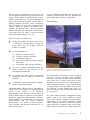
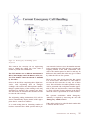
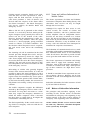
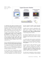
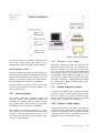
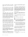
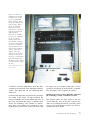
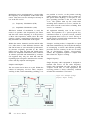
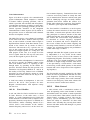
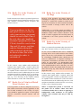
Figure I.I
Shared Police and Fire Service Site
(Photo: Bedfordshire and Luton Fire & Rescue Service
The Home Office VHF bands are used to support
wide-area coverage schemes using dominant
radio sites. Such sites are often shared with other
users. These may be other Police forces or Fire
Brigades as well as private users. Often the Police
and Fire Brigade will have several radio channels
covering one part of the operational area. At each
site, therefore, several transmit and receive frequencies from the same and different bands will
be in operation.
The Home Office Frequency Management Group
(FMG) offers a free service which can advise
Police forces and Fire Brigades on the frequency
compatibility of site sharing applications. FMG
utilises specialist software to predict the spurious
signals that may be generated when several transmitters operate on the same site. Some of the spuri-
Communications and Mobilising
9
ous signals may cause interference to co-sited base
receivers or to mobiles which may be close to the
site.
When considering site sharing applications,
Communications Officers are strongly advised to
seek assistance from their engineering advisors on
the likely wind loading of the additional aerials and
the resultant overall wind load on the mast. The
overall capacity of the power supply to the site also
needs to be assessed. Further advice can be found
in the relevant Policy Statement on site sharing.
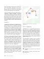
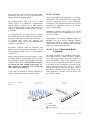
Retained Firefighter Alerter Systems
Fire Alerter systems used by Fire Brigades operate
on a 25kHz bandwidth FM alerter channel in the
VHF highband portion of spectrum.
The Home Office RFCPU allocate the alerter tones
to brigades. The country has been divided into
hexagonal cells 50 km across, with each cell being
divided further into 127 smaller cells with each
smaller cell being 5 km across. Seven codes are
allocated to each smaller cell, making a total of
889 codes. Fire stations are allocated codes on the
basis that the minimum reuse distance is 50kms.
All equipment must be type approved by RFCPU.
Licences allowing Fire Brigades to operate the
above type of alerting system will be withdrawn
after 31 st December 1998. Thereafter, systems will
comply with MG-4.
MG4 Specification Systems
In 1991 a new alerter system specification was
introduced, produced to Home Office Specification MG-4 (Issue 2), which employs a recognised
industry standard signalling system know as POCSAG (Post Office Code Standardisation Advisory
Group). The transmitters operate at a maximum
output of 25 Watts Effective Radiated Power
(ERP). The system architecture is structured to
provide each brigade with a unique coded address,
together with up to 2000 separate address codes
which may be allocated within the brigade to a station, a team or individual as required. (Radio
Frequency Policy Statement FPS 7 refers)
10
Fire Service Manual
All MG-4 base station transmitters must comply
with the Radiocommunications Agency Specification MPT 1325 and Home Office Specification
MG-4 (Issue 2). Base station aerial heights MUST
NOT exceed 10 metres above ground level without
the prior approval from RFCPU.
Communications
and Mobilising
Chapter 2 - Fire Control Centres
The Fire Service Act 1947 Section l(i)(c) requires
Fire Authorities to secure the provision of efficient
arrangements for dealing with calls for the assistance of the Fire Brigade in case of fire and for
summoning members of the Brigade.
To meet this duty, fire authorities usually have a
continuously staffed mobilising and communications centre, equipped with computer based
Command & Control systems to deal with the
receipt of emergency calls and the alerting and
despatching of fire service resources within its
mobilising area. Although these are considered to
be the 'core' activities of a Control Centre, many
additional 'non-core' duties are performed by control personnel as stipulated by the Chief Fire
Officer/Fire Master.
All emergency communications for the Fire
Service are channelled through the Control Centre
which acts as a general communications and information resource for the Fire Brigade. It is usually
housed in either a Control Suite at Brigade
Headquarters or in a purpose built building within
the County.
A Control Centre is staffed (in shifts to provide 24
hour cover) by uniformed professionals who,
although employed under different conditions of
service to Fire Fighters, are an important part of
the Fire Service.
Secondary and tertiary control systems are also
maintained to ensure a continuity of service. There
are no national standards of'efficiency for handling
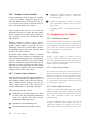
fire calls but many Chief Officers have set their
own standards which are set out in Brigade
Orders/Service Instructions or their Citizens Charter.
In most cases the Control Suite comprises a
Control Centre, training room, offices, equipment
rooms, kitchen/rest-room, store rooms, lockerrooms/toilets, etc. These rooms and facilities
should be well designed and within easy access of
the Control Centre room.
Control personnel performing duties away from the
Control Centre may need to be recalled if there is a
sudden spate of calls, or personnel become busy for
other reasons. Easy access from anywhere within
the suite will enable personnel to respond quickly.
Comprehensive guidance on the design of
Control Centres was issued in DCOL 8/1997 (in
Scotland as DFM 8/1997) (FRDG Publication
2/97). This is an updated version of Volume 5 of
the Home Office Guidance usually referred to as
'Logica'.
The document includes advice on the Control
Centre design & ergonomics, procurement and
legislation.
The recommended Control Centre rank structure is:
Fire Control Operator
Leading Fire Control Operator
Senior Fire Control Operator
Fire Control Officer
Group Fire Control Officer
Principal Fire Control Officer
FCOp
LFCOp
SFCOp
FCO
GFCO
PFCO
Not all these ranks are represented in every Brigade.
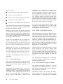
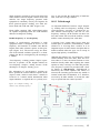
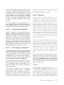
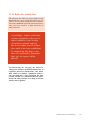
2.1 Basic Call Handling Procedures
The primary function of a Control Centre is to
provide the essential communication link which
enables the provision of emergency firefighting,
rescue and humanitarian services to the public
when they call for assistance.
Communications and Mobilising
11
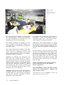
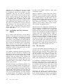
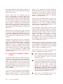
Figure 2.1 Fire
Control Centre.
{Photo: Counts' Durham and
Darlington Fire ami Rescue
Service)
The basic principles of running a Control Centre
have a common theme. However, the responsibilities and accountability of each rank may vary
depending upon the size of the brigade.
It is possible that the caller may be in some personal danger. It is easy to understand that such circumstances might create a wide range of behavioural responses on the part of the caller.
The detailed procedures for handling an emergency call differ in each brigade according to its
size and the type of communications and mobilising systems used.
Traditionally, Fire Control Operators are taught
the appropriate inter-personal skills by a combination of initial training including simulation exercises and 'on the job' training by experienced personnel.
Fire Control Operators are trained to elicit information from those calling for assistance. This
activity requires the identification of the incident
address and confirmation of the type of emergency
for which assistance is required.
Difficulties in obtaining this information may
result if the caller is unduly anxious or excited. A
Fire Control Operator will still need to bear in
mind the primary purpose is to obtain information
and will need to use effective call handling skills to
overcome these difficulties, possibly by calming
and reassuring the caller. It may be necessary to
give advice for dealing with the emergency whilst
waiting for fire service attendance.
Techniques used to achieve this could include a
sympathetic approach or perhaps, the adoption of
an authoritative tone. The exact style being dependent upon the Operator's perception of what is
appropriate in the circumstances.
12
Fire Service Manual
The first contact an emergency caller has with the
Fire Service is with the Fire Control Operator. The
way the operator handles the call is vital and to
this end the operator must be immediately available to take control of the call. This will enable
effective collation of call details to mobilise, and
will indicate to the caller that they are being dealt
with efficiently.
Further information on the training of Control
Centre personnel is given in the Training
Section (Appendix I).
The responsibilities of each rank within Control
Centres vary from Brigade to Brigade and
many of them overlap.
The following list gives examples of skills and
responsibilities within each rank.
Control Operator (Core Skills)
Receive emergency calls.
Give advice to emergency callers as required.
Identify and dispatch appropriate fire brigade
resources to incidents, (if necessary receiving
guidance from senior ranks).
Regulations 1992.
Comply with the Brigade's Equal
Opportunities Policy and other relevant legislation at all times.
Undertake control/watch
duties as required.
administration
Leading Fire Control Operator
Be familiar with the location of fire stations
and their station ground.
Keep officers informed of incidents/occurrences as required.
Liaise with other authorities and resources to
keep them informed of incidents and request
their assistance if necessary.
Answer radio messages, relay radio messages
to appliances and officers and act on information obtained.
Deputise for Leading Fire Control Operators
in their absence, subject to Brigade requirements and competence of the Operator.
Test and inspect equipment held in control,
and the secondary control, carrying out such
first line maintenance as appropriate.
Answer non-emergency switchboard calls out
of office hours and direct/advise callers.
Answer non-emergency calls from station
personnel and act on information received.
Complete incident statistics.
Work as part of a team and react appropriately as instructed and directed by officers.
Duties mirror those of a Fire Control
Operator with the addition of supervisory
duties.
Assist and support other officers and be
responsible to the Watch Officer in respect of
the day-to-day, management of the Control
centre and development of personnel.
Deputise for a Senior Fire Control Operator
in their absence.
Assume duties as Watch Officer in the
absence of a Senior Fire Control Operator
and/or Fire Control Officer, subject to
Brigade requirements and suitability of the
Leading Fire Control Operator.
Participate in the design, programming, running and monitoring of training programmes.
Provide support and guidance to probationary
Fire Control Operators and personnel preparing for examinations.
Be familiar with the general command principles necessary to undertake the variety of
other such tasks and duties as may be
required, to meet the needs of the Brigade.
Senior Fire Control Operator
Ensure that levels of personal conduct are
maintained in accordance with the standards
prescribed in the Fire Service (Discipline)
Regulations 1985 and by accepted Service
Procedures.
The tasks listed below may be the responsibility of
a L/FCOp in Brigades that have S/FCOp's as
Watch Officers.
Ensure compliance with current Health and
Safety Legislation, including Display Screen
Take charge of Command and Control activities during the absence of the Watch Officer.
In addition to the L/FCOp duties:
Communications and Mobilising
13
Assist and support the Watch Officer in
respect of the day-to-day management and
development of personnel.
Ensure that all resources have been dispatched correctly.
Prepare and carry out watch training programme, and maintain training records as
required by the Fire Control Officer.
Undertake administrative/project work as
required and assist in the supervision and
completion of Control/Watch administrative
workloads.
Fire Control Officer
Group Fire Control Officer
In some cases an FCO or GFCO may also hold
other references within the Brigade. These may
include Personnel Officer, Communications
Officer or, for example, in larger brigades the
Watch Officers may hold the rank of GFCO.
The tasks listed below may be the responsibility of
an FCO in a brigade which does not employ a
GFCO:
Responsible for the overall management of
the Control Centre, its personnel, equipment
and all other resources to ensure the effective,
economic and efficient operation of the
Control Centre, in line with Brigade policies
and procedures.
In addition to the above:
Monitor emergency calls and take command
of the dispatch of all resources.
Ensure that fire cover is maintained throughout Brigade area, utilising resources from
neighbouring Fire Brigades if necessary.
Ensure compliance with all Brigade
Instructions, policies and guidelines.
Identify training needs and manage the
design, programming, running and monitoring of training.
Management of Control/Watch administration duties including financial responsibilities
as required.
Assist and support other officers and be
responsible to the Group Fire Control
Officer (if applicable) in respect of the day
to day management and development of personnel.
This may include conditions of service, sickness monitoring and welfare issues.
Assist and support management in the development and planning of mobilising strategy.
14
Fire Service Manual
Attend control during a major incident or
spate conditions, and take strategic command
and provide support as appropriate.
Keep Control personnel informed of Brigade
policies, procedures and standards.
Monitor the welfare and motivation of personnel whilst constantly seeking to promote
and improve teamwork and efficiency.
Establish an effective working relationship
with Control personnel.
Monitor all Control Centre personnel in
respect of performance, conditions of service
and training where appropriate.
Development and planning of mobilising procedures.
Development and planning of control/station
communication systems.
Maintain an efficient and effective Command
and Control centre within allocated budgets
provided.
Principal Fire Control Officer
The Principal Fire Control Officer rank is usually
used in the larger metropolitan brigades and generally performs the same role as FCO/GFCO in
managing the Control Centre. Other brigades may
introduce the rank to lead special projects or be
head of section for the Centre i.e.,
Command/Control/Communications and IT, or
perhaps perform the management function of a DO
with
responsibilities
for
Personnel
&
Development, Equal Opportunities or Health &
Fire Service Inspectorate to ensure correct interpretation and to develop a common approach.
HM Fire Service Inspectorate does not currently
recommend a Grade of Service but may do so in
the future.
Additionally, Fire Service Circular October 1975
recommends rank levels for control personnel
established by reference to the population within
the Brigade area.
However, in some Brigades the PFCO may be
responsible for developing brigade mobilising policy as part of the Principal Management Team.
2.2 Control Centre Staffing Levels
Her Majesty's Fire Service Inspectorate (and the
Scottish Office Fire Service Inspectorate) is
charged with the duty of obtaining information on
how fire authorities are performing their functions,
with particular regard to efficiency and effectiveness. Included in these functions are the brigade
Control Centre and the manner in which it is
staffed and operates.
To assist HM Inspectors and brigades in setting
staffing levels within the Control Centre, a
Staffing Model has been developed. This model
was issued to brigades as DCOL 6/1996 (in
Scotland as DFM 6/1996).
The model is designed to give an indicator of the
number of operators required to handle and
process a given workload to a given Grade of
Service. The model is not intended to take into
account levels of supervision, sickness, training or
control personnel required for projects, etc. It is
used as a means of determining the number of
operators required, from which decisions regarding establishment and officer levels can be made.
HM Inspectors will also use the model to assess
the adequacy of brigade staffing requirements.
Brigade managers are, of course, free to run the
staffing model within their own brigades. However,
the Home Office recommends liaison with HM
Communications and Mobilising
15
Communications
and Mobilising
Chapter 3 - A brief history of the
'Fire Control Centre'
In 1997 the Fire Service as we know it was 50
years old, over those years a new career has
evolved; that of Fire Control Operator.
In the very early days strategic mobilising to fires
was virtually non-existent. During the 1800s,
numerous fire insurance companies formed their
won brigades of 'watermen'. Following a call to
'fire', sometimes several of these Insurance
Brigades would send their 'engines' and, on
arrival, would look for the 'fire mark' to establish
whether the victim was insured and by which
company. In the free for all that ensued, the
brigades could find themselves working against
each other instead of working for the common
good, to the detriment of the public. There was little co-ordination of resources or direction of the
overall situation.
Over the next century and a half that was to change
significantly.
One prime innovation which would start the long
haul to a unified well organised service, was the
Metropolitan Fire Brigades Act, 1865. The act
covered the City of London and 'all other Parishes
and Places for the Time being within the
Jurisdiction of the Metropolitan Board of Works'.
The Act also stated the need 'for the establishment
of Telegraphic Communication between the several Stations in which their Fire Engines or Firemen
are placed, and between any such Stations and
other parts of the Metropolis'.
This enabled the receiving and transmitting of locations of fires to all stations connected by the telegraph system. It was the first indication of mobilising from a source remote from the location of the
fire and, by necessity, carried out by a fireman at
the fire station receiving what was called a 'running
call'. A situation that exists to the present day.
Previous page
is blank
Metropolitan Brigades had an advantage over the
smaller rural Brigades by nature of their size and
the population they served. They were far better
equipped financially to exploit the new technology
that appeared, such as a street fire alarms and fire
detectors in commercial premises.
In rural areas, private telephones were scarce and
public telephones were not as plentiful or well situated as they are today, and there were no street
fire alarms. The firemen in rural brigades were
usually part timers who would rely on being called
by a 'knocker up' or by the sirens that were
installed during the First World War. These sirens
were still in use well into the 1970s.
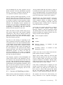
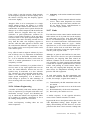
With war approaching, the government mounted a
recruitment campaign to encourage men and
women to join the Auxiliary Fire Service (AFS).
Women were encouraged to join as drivers, or to
work in fire stations doing office work or watchroom duties. Some women opted for motorcycle
training and driving lessons, while the majority
learned watchroom procedures and the vital
process of mobilising appliances. They all had
basic firefighting training. (The AFS became the
National Fire Service approximately one year after
the war started. It was reformed in 1947 to run
until the mid sixties.)
One of the difficulties of forming a large number
of small brigades into a National Fire Service was
that most of the equipment, hose couplings, pump
deliveries and appliances, etc., were all different.
This caused obvious problems when one brigade
was called to assist another. There was a desperate
need for standardisation.
All emergency calls were received at the local
General Post Office (GPO) Telephone exchange,
(at this time telephone exchanges only covered a
Communications and Mobilising
17
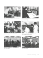
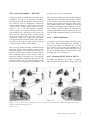
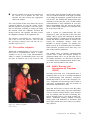
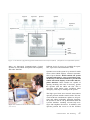
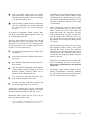
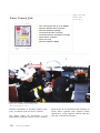
Figures 3.1 and 3.2 Posters used during a recruiting campaign in World War II.
small area and there were a great number of them),
and passed to the Wholetime fire station in that
area where a 'Watchroom' was continuously
manned, either by a firemen, firewomen or a combination of both.
After the Second World War, communication was
still a laborious and lengthy process. Watchrooms
or Control Rooms in various brigades evolved differently, some were staffed by firemen who had a
rota for 'Watchroom' duties while others were
staffed by firewomen who had served in the
National Fire Service. Many of these women
stayed on after the war to become the forerunners
of today's control operators.
In 1947 the Fire Services Act was passed to make
further provision for fire services in Great Britain
'to transfer fire-fighting functions from the
18 Fire Service Manual
National Fire Service to fire brigades maintained
by the councils of counties'. With brigades under
the auspices of the County Councils the long
process of standardisation of all equipment continued. This included the amalgamation of some fire
station watchrooms into divisional control rooms
which, because County Councils were also responsible for the ambulance service, were sometimes
shared with ambulance personnel.
Unfortunately, whilst World War Two had produced some well managed and equipped fire control rooms up and down the country under the
NFS, these were thought to be too elaborate for
county brigades, and were dispensed with.
Mobilising was still carried out by the duty
watchroom attendant who would take call details,
dispatch the first attendance and, if necessary,
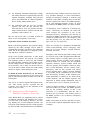
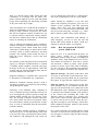
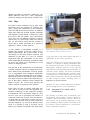
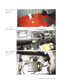
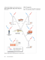
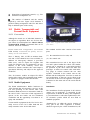
Figure 3.3 London Fire Brigade Control Room, 1937.
(Photo:LondonFireBrigade)
Figure 3.4 London Fire Brigade Wireless
Control Room at HQ.
( Photo: London Fire Brigade)
Figure 3.5 AFS Fire Women in Watch Room.
(Photo: Kent Fire Brigade)
Figure 3.6 GPO Telephone Exchange, late 1960s.
Note red lightbulb for 999 calls.
(Photo: Hertfordshire Fire and Rescue Service)
Figure 3.7 Kent Fire Brigade Control Room, I960.
Figure3.8
(Photo: Kent Fire Brigade)
( Photo: Kent Fire Brigade)
Control Room using VF System 'A', 1980.
Communications and Mobilising
19
pass the call to a divisional or district control.
It was the duty of the watchroom attendant to
record all fire calls, as well as officer and
appliance movements, in the 'log book'. In fact
everything was meticulously recorded, usually in
beautiful handwriting.
attendance (PDA) card for the parish or street to
determine which appliance/s to send before alerting the station/s. These cards were kept in large
'bins' in the control room and if the brigade used
street mobilising there were many hundreds of
cards.
In some cases, Kent for instance. Brigade controls
were responsible for plotting, logging of all calls
with associated paper work, fire reports, accident
reports and statistics, but not at any time talking to
the originator of the call.
Operators prided themselves on their topographical knowledge and remembering the attendance
for many areas or special risks, only using the
PDA cards for confirmation. Fire calls were
recorded by hand on individual incident forms
and, in some cases, the old 'log book' was still running!
Improvements in the telephone network had revolutionised brigades. The introduction of a radio
network was the next step towards improving
brigade-wide communications.
The radio scheme was sometimes shared with the
Police (provided fire control asked 'nicely' and the
police were not too busy, the scheme would be
opened to allow for transmission) or, sometimes, the
scheme was shared with another brigade. Police and
Fire Brigade radio schemes were the responsibility
of the Home Office Communications Branch, later
the Directorate of Telecommunications, and
remained so for many years.
These early systems, although now construed as
relatively primitive, were to further enhance the
capabilities of the service. Once each Fire Brigade
had their own private mobile radio networks it
became more practical to operate the radio from
one location. It was one more step towards a single
control.
Contact with fire stations was made by land line
and 'part timers' or retained firemen were called in
by housebells or sirens, alerters for retained firefighters were not introduced until 1968.
Control rooms were now capable of reliable contact with stations by means of the 'K system' and
subsequently, among others, the VF 'system A' and
private wires, all of which used land lines. These
mobilising systems were very reliable but rather
slow, the method used to communicate with the
station or stations required was the human voice,
and all turn-out instructions, with additional information if necessary, were repeated. Mobilising
was accomplished by checking the pre-determined
20
Fire Service Manual
At this time, nationally, control staff personnel
were a mishmash of backgrounds and experience.
Control was thought to be the easy option and
many operators were firemen who were on the run
down to retirement, or sick and on light duties.
Some brigades started to employ women because
they couldn't get men to work shift work for the
low rate of pay. Others, of course, had long established specialised personnel.
The developing use of computers generally in the
1970's inevitably led to thoughts of computerised
mobilising. To have finger tip control of all brigade
resources, PDA's, call logging, statistics and instant
recall of information seemed very exciting. There
was talk of 'paperless' control rooms! In fact
because of this belief many of the consoles
designed at that time had no 'working' space. This
mistake was rectified next time around.
In 1972 two new courses were introduced at the
Fire Service College, one was for Communications Officers, a post usually occupied by an
operational fire officer, and the other was the very
first course especially for Control Room staff, a
Supervisory Officer's course. By 1974, in part due
to Local Government reorganisation, the concept
of a central control room for each County was well
established. This was also the year in which Local
Area Health Authorities were formed and Fire
Brigades and the Ambulance Service went their
separate ways.
1975 saw the standardisation of Control staff rank
structure and markings, and recruiting was geared
to the special skills required of an operator.
Grampian Fire Brigade was the first to use computer aided dispatch, closely followed by Greater
Manchester Fire Brigade who went live with a
fully computerised Ferranti Argos system in 1979.
By the late 1980's almost all of the Fire Brigades
in the United Kingdom had a computerised mobilising system although some were more sophisticated than others.
The number of emergency calls is increasing year
by year, as is the type of emergency. To reflect the
diverse nature of fires and special services they
now attended, many Fire Brigades have changed
their title to 'Fire and Rescue Service'.
The Control Centre as the name implies is, by its
very nature, an essential part of any Fire and
Rescue Service. Instead of the free for all of the
early days, firefighters can rely on being well
informed about the incident they are attending,
being kept up to date with all developments as they
occur, and have the knowledge that requests for
help or assistance will be quickly and efficiently
acted upon.
The skill of the operational firefighter together
with the professionalism of their colleagues in the
Control Centre, combine to provide an efficient
and effective service to the public.
The Home Office Guide to Fire Brigade
Mobilising Systems, known as the 'Logica' report,
was published in 1990 to help Brigades with the
specification, procurement and support of their
second generation mobilising and communication
systems.
Long gone are the days when all that was required
of the watchroom attendant was to wind a handle
for the station to turn out to a fire and hope that
contact was made. The requirements and expectations of the control room has changed, and the
improvements in communications have enabled a
faster and more effective response.
Nowadays local knowledge is not enough, even
the most experienced Control Centre Operator
could not retain the large quantities information
required by a modern Fire Service. All incidents
and relevant information are logged and stored on
the database of modern computerised mobilising
systems.
An operator now requires keyboard skills and a
knowledge of computers: retrieval and statistical
systems: chemical and hazardous material,
Management Information Systems (MIS): mapping systems and most importantly, call handling
techniques.
An operator also needs to have a basic understanding of the many communication systems, be they
voice or data, that are used in the fire service. In
fact it is becoming increasingly difficult to distinguish between Communications, Mobilising and
IT systems.
Communications and Mobilising
21
Communications
and Mobilising
Chapter 4 - T h e 999/112
emergency service
4.1 BT
The Public Telecommunications Operators (PTOs)
are obliged, under the terms of their licences, to
provide a public emergency call service by means
of which any member of the public may, without
charge, communicate as quickly as practicable
with any of the appropriate local emergency
authorities (EAs) to notify them of an emergency.
The 999 call service provides national coverage in
respect of the four main emergency services, i.e.,
police, ambulance, fire and coastguards. Other services can also receive emergency calls via the
police. These organisations are cave rescue, colliery rescue, mountain rescue, air/sea rescue, diver
emergency and cardiac units.
BT takes approximately 21 million calls each
year, including 2 million mobile 999's and calls
from cable networks. Cable & Wireless (formerly
Mercury) take 2.8 million including mobile and
cable
company
calls,
whilst
Kingston
Communication handles 200,000 calls. Requests
for police help account for some 55 per cent of
emergency calls, while the ambulance service
accounts for 33 per cent and the fire brigades for
the majority of the remaining 12 per cent. Some 50
per cent of all 999 calls are false calls, where
callers make no request for an EA, and are safely
filtered by BT and Cable & Wireless operators at
the request of the EAs using agreed procedures.
4.1.1 The British Telecom fixed telephone
system
There are fifteen BT Operator Assistance Centres
(OAC), these are at Aldershot, Aylesbury, Bangor,
Belfast, Blackburn, Bristol, Cambridge, Glasgow,
Hastings, Inverness, Leicester, Newcastle,
Newport, Thanet and Warrington.
Previous page
is blank
Figure 4.1 A BT Operator Assistance Centre.
[Photo:BT)
The trunk reservation facility will be used to
ensure that there will always be at least two circuits reserved for 999/112 calls on a route from a
digital local exchange. More importantly, however, this facility allows an additional circuit to be
reserved for a 999/112 call each time an existing
circuit is taken into use for a 999/112 call. All of
the circuits in a route are thus, potentially, available for emergency use. This gives protection in
disaster situations which cause a sudden surge of
999/112 calls.
If it is not possible to route operator traffic to the
primary operator centre due to congestion or failure within the network or evacuation of an
Operator Assistance Centre, 999/112 traffic will be
routed to an alternative OAC.
The connection of an emergency call involves four
main phases:
Communications and Mobilising
23
(1) Connection of the caller to the operator via
the 999/112 code;
(2) Selection by the operator of the required
Emergency Authority Control Centre
(EACC);
(3) Onward connection of the caller to the
EACC; and
(4) Confirmation that the connection has been
established with the appropriate EACC and
ability to provide further assistance to the
caller or EA when required.
The operator will monitor the call until the caller
has passed their location and is clearly giving
details of the incident. The operator normally
holds the call in the system without listening
(unless there are difficulties) until both the caller
and EA have cleared the line.
It is the responsibility of the EA Control Centre
staff to obtain adequate address information
from the caller to enable the EACC to locate the
incident being reported.
4.1.2
Operator call-handling procedures
The action of dialling 999/112 on BT's public telephone network in the UK automatically routes the
caller through to a designated Operator Centre.
Here, if it is not immediately answered, the call is
visually and audibly signalled on all operating
positions and, in addition, a special red light operates to ensure that the call is given immediate
attention by a BT operator.
To cater for unforeseen circumstances EAs have to
provide three separate routes from the Operator
Services Centres to the emergency service. The
secondary and alternative routes would normally
be used in sequence in the event of an unusually
high level of traffic or a fault on the primary route.
BT will allow a 30 second delay with no reply
before another route is attempted unless the EA
control centre has a call queuing system, in which
case additional time is allowed. For this reason it is
vital to inform BT if any call queuing system is
installed.
24
Fire Service Manual
These routes are:
Primary
This is the route that the PTO operator will
initially use to connect a caller to the EACC
and the EA must provide sufficient capacity
on this route to handle normal 999/112 trafficdistribution.
EAs will reserve primary routes exclusively
for receiving 999/112 calls.
Secondary
In circumstances where the PTO operator
receives no replyon the primary number after
30 seconds, the operator will connect the call
to a secondary number provided by the EA,
except where call queuing is used. This procedure should only be necessary in instances
when the EACC has an unusually high level
of traffic or a fault in its switchboard or one
of the PTOs' networks.
Alternative
In the event of a major problem which results
in the primary and secondary routes to an
EACC being unavailable to the PTOs, the EA
should provide the PTOs with an alternative
means of taking delivery of the call, ideally at
a different EACC for maximum security.
To provide adequate security, this alternative
number must be served by a different network route from that providing the primary
and secondary routes. EAs would have to
consider, where appropriate, which EA
Control Centres are used as alternatives to
each other.
These routes are agreed between the EA and the
BT Emergencies Services Manager. Changes
arranged by EAs have to be notified directly to
the ESM giving at least two weeks notice.
All the routes have to be staffed on a 24 hour
basis.
When a PTO operator answers an emergency call
that has originated from a digital exchange, the full
national calling line identity number (CLI) will be
automatically displayed on the operator's VDU.
Figure 4.2 BT emergency call handling system.
(Diagram: BT)
This removes the necessity for an engineering
trace to identify the calling line if the caller is
unable to provide this information.
The CLI number uses a different mechanism to
BT's Caller Display and Call Return (1471) service. The number cannot be altered or withheld
by the caller.
Prior to all the PTOs completing their digital networks, calls originating from an analogue
exchange will not show the full telephone number,
though a partial display of the exchange code may
sometimes be obtained. The customer may therefore still need to be asked for their number in order
to route the call correctly.
The originating calling information (CLI) will be
used to automatically display details of the appropriate EACC connect-to numbers.
It is worth noting that an increasing number of
business customers have DDI systems and/or pri-
vate networks. In these cases, the number automatically presented to the PTO operator is usually the
outgoing number of the main switchboard. This
will be the number passed to the EA and may be
different to the number the caller may give if asked
by either the PTO or EA operator.
There are also some private networks that extend
over several areas. Their 999/1 12 calls could be
fed into the PTO networks in only one of these
areas. This will lead to inevitable problems as they
will be presented with a telephone number applicable to this area and, therefore, routed accordingly. These will only become apparent at the EACC
when the caller is questioned as to their location.
The operator establishes which Emergency
Authority is required by answering the call with
'Emergency, which service?'
If the caller needs to be asked for their number this
is entered onto the screen.
Communications and Mobilising
25
The operator hands the call over by passing the
Operator Assistance Centre (OAC) name and the
caller's number and listens while the caller passes
their location. If this has been given clearly and the
call is progressing, the call will be held in the operator's system (without listening) until the call is
complete. Operators normally listen throughout in
difficult cases, for example, panicking callers or
where there is a language problem.
If it is necessary to speak to the BT operator again
it should be possible to call them back onto the line
while the call is being listened to. At this stage of
the call there are two options to speak to the BT
operator.
(1) Operators can normally see when the caller
and the EACC have cleared. If the EACC has
the necessary facilities it is possible for EA
operators to cause the word 'Flash' to appear
on the BT screen.
(2) The operator may be alerted by failure to clear
the line, although this may take some time if
the operator is dealing with another call.
If details of the call are required once the call has
been released, it will be necessary to dial the Operator
Assistance Centre number allocated to each Brigade.
The allocated number should be used even if the
call was passed via a different OAC.
Every emergency call is recorded both on magnetic tape and on a call printout which shows basic
call details, such as time, telephone number and
address of the call. BT's recording of emergency
calls is from the time that the call is answered by
the BT operator to the time when the call to the EA
is cleared by the caller and the EA, the speech of
all parties is recorded. All 999/112 call records are
held for three months.
4.1.3 Mismatches between EA and Fixed
Network Operator Boundaries
BT has over 7500 exchanges, each with its own
code, it is these codes that determine how the call
is routed. BT exchanges have grown up over the
last 90 years as the cable network has evolved and
each has a defined catchment area averaging 4km
in radius.
26
Fire Service Manual
Exchange area boundaries do not always coincide
with EA boundaries. Where 'mismatches' exist,
careful planning and general agreement between
neighbouring Chief Fire Officers/Fire Masters and
the BT Emergency Services manager has to be
reached on which EA Control Centre will take the
calls from the whole of the split exchange area in
question.
The Fixed Network Operators will connect all
directly connected customers to the appropriate
EACC for the agreed geographical areas wherever
possible. It will be the EA's responsibility to pass
information if necessary to another EACC in these
mismatches cases.
4.1.4 Provision of ex-directory
information
BT operators will only provide name and address
information for numbers from which a recent
999/112 call has been made. All other routine
requests for such information must be made by
EAs through BT's Network Special Investigations
Group.
In providing an XD/NC service BT undertakes not
to give the number to anyone outside BT including
EAs. BT has laid down procedures to enable
urgent calls to be connected to XD/NC customers
without revealing the number. EAs requiring such
a connection must contact BT OACs using 100
service where the operator will ask a number of
questions to support the request before connecting.
4.1.5 Access to tape recordings of
Emergency Calls
BT will record all calls terminating on 999/112 circuits. Calls are recorded from the time the call is
answered by a BT operator until the EA and caller
clear the line, and the circuit is released.
Requests from EAs to listen to, to make notes
about, or be given a copy of a recording of a
999/112 call must be referred to the BT Network
Special Investigations Group.
These requests must be authorised by the agreed
level according to the Code of Practice which
states:
Access to emergency call records can be obtained
in two forms:
Normal For investigatory purposes where it is
required as evidence or similar use.
Arrangements for access will be agreed
at the time of request.
Urgent
Where instant access is required to
respond to a 999 incident. (Current
equipment means this would take several minutes.)
The authority levels for access required are:
Normal
Duty Principal Officer
Urgent
Senior Duty Control Room Officer
An authorised representative of the EA (not necessarily the Authorising Officer) must be present
when the tapes are being played at an Operator
Services Centre.
an enhancement which would allow the telephone
number and address of the caller to be automatically displayed on the EAs own mobilising computer screen.
The advantages of CLI are:
Caller's number and address automatically
available on answer, no need for information
to be passed verbally or the EA operator to
type. Reduces typing errors.
Name of BT OAC displayed, for call back if
necessary.
Caller can speak to the EA sooner, reducing
frustration or panic. Address and telephone
number is simply confirmed.
CLI overcomes the problem of spelling, pronunciation and language difficulties.
BT will only keep original 999/112 recording tapes
for a period of 3 months. Evidential quality copies
can be requested if necessary.
Early indication of hoax calls - the autoaddress will reveal if the caller is giving a
false address or at a payphone often used to
make malicious calls, or perhaps a mental
hospital.
BT will apply to the Chief Officer of the relevant
EA for similar recordings of calls made by the
EAs.
As mobile zones decrease in size the automatic Zone Code may help EAs to question
callers who are unsure of their location.
PTO's inform all their customers to use the
999/112 code when making emergency calls.
PTO's do not tape record emergency calls made on
any other circuit. However, such calls are
processed despite the use of the incorrect code.
BT have devised a system which requires an ISDN
link from that operator centre which is used to forward CLI to the EACC. On receipt of a call the
EAs mobilising system will dial into the BT database for address information which will be displayed on the EA mobilising screen, this will take
less than 10 seconds, (a pilot trial in place at this
time is providing the information in one second).
This is technically a dial-up system (which will
have a small cost implication for the EA) but will
appear automatically to the EA operator.
4.1.6 Calling Line Identity (CLI)
Since 1985 BT have been modernising their network and converting from analogue to digital
exchanges. This modernisation is almost complete
giving 99% CLI coverage, which means BT operators have instant access to the callers address on
40 million lines.
Once BT developed CLI for their own operators,
the emergency services requested an enhancement
to 999 services to reduce call handling times and
the number of hoax calls. Their requirement was
Trials of this system have commenced in the
Ambulance service and will shortly commence for
the Police. The Fire Service (CACFOA) have
decided to wait for the long term strategic solution,
when, once European Standards have been developed, should allow CLI name/address to be passed
together.
Communications and Mobilising
27
The trials assess:
The performance of the technical solution.
Processes such as audit trails.
The most cost effective packages for rollout.
Savings in time to despatch (EA).
appropriate EA Control Centre (Police, Fire,
Ambulance and Coastguard). In addition the
Network Operations Unit draws attention to the
fax by telephoning the Police control, which in
turn telephones the other affected EAs. If necessary, progress reports are faxed at periodic intervals and finally a fault clearance report is sent once
999 access has been restored. The process includes
the provision by BT to the EAs of maps showing
the area covered by each of its exchanges.
Reduction in call handling times (BT and EA).
The results of these trials will give BT information
which will be used for the long term solution when
the European standard is agreed.
Whichever system is used, it will only be possible
to automatically obtain the telephone number and
address of the caller if they have dialled 999 or
112. The system design dictates that these calls follow a certain technological route which safeguards
the integrity of the BT system.
It will not be possible for any EA to type in a
number and interrogate the BT database. By
the act of dialling 999/112 it is deemed a caller has
given consent for this information to be used and,
therefore, complies with the Data Protection laws.
Although in most cases the emergency call is
made from the address of the fire, it should not
be assumed that this is so. Experienced EA operators will recognise the dangers and know how easy
it is to get an affirmative answer to any question.
Training on call handling procedures will have to
reflect this.
4.1.7 Network Resilience
In the event of a major failure to a part of a PTO's
network, the PTO will notify the affected EAs as
soon as possible after the failure is identified, or is
anticipated.
The process for informing EA's of any BT
exchange that fails to give customers 999 access
commences when a regional Network Operations
Unit (NOU) detects a failure that causes loss of
999 access. Once the extent of the problem is
known a report of the failure is faxed to each
28
Fire Service Manual
EAs and relevant PTOs should prepare local
contingency arrangements to cover the receipt
of emergency calls during conditions of serious
breakdown in the PTO network.
4.1.8 Priority Fault Repair Service
The conditions in the PTO's licence requires them to
provide a free Priority Fault Repair Service to those
emergency authorities who receive 999/112 calls on
lines connected to the PTO's network. When notified
of any fault or failure which causes interruption, suspension or restriction of the telecommunication services provided by the PTO, the PTO will restore
those services as swiftly as practicable and with a
priority, so far as is reasonably practical, over Fault
Repair Services to other persons.
Where an EACC has connection directly to a PTO
for an Emergency Call Service, Priority Fault
Repair Service will be extended to all 999/112 circuits in accordance with the relevant condition of
the PTO's licence. This is Condition 9 of the Cable
& Wireless licence and Condition 10 of the BT
licence.
The BT Priority Fault Repair Service will apply
where BT and Cable & Wireless use common terminations supplied by BT.
4.1.9 BT National Emergency Linkline
The National Emergency Linkline is a service
designed to give nominated customers a quick and
easy means of contacting BT to request assistance
during emergency situations.
Nominated customers are primarily the Emergency Services and Local Government, as they
would normally be responsible for co-ordinating
emergency incidents. However, the service can be
made available to Health Authorities, the Armed
Forces and those public utilities that are likely to
play a significant role in major emergencies.
The National Emergency Linkline number
must not be disclosed outside the organisation.
This will ensure the service is not abused by unauthorised users.
This service has been specifically set up for use in
the event of Civil Emergencies and major disasters. It is NOT for normal business enquiries.
To get more information (including the National
Emergency Linkline number) contact the local BT
Zone Emergency Manager.
BT's modern digital technology uses a flexible call
routing tool known as Advanced Linkline Services.
This facility can direct calls from a special national telephone number to one or more pre-selected
answering points. The National Emergency
Linkline number dialled from anywhere in the UK,
connects the caller to the nearest Emergency
Linkline reception point, normally the local BT
Network Operations Unit. The NOU will ensure
that a request for assistance is handled promptly
and that all necessary parts of BT are alerted.
4.1.10 (Government Telephone Preference
The service is available 24 hours a day.
When requesting assistance a caller must identify
themself and the organisation that they represent
and provide a telephone number on which they, or
another representative, can be contacted. They
should give as much detail about the incident as
possible to enable BT to react quickly.
The information should include:
Scheme
The Government Telephone Preference Scheme
(GTPS) provides a contingency facility for the withdrawal of outgoing telephone services from the
majority of customers on a telephone exchange. The
scheme is designed for use in a serious crisis when
increased use of the telephone network is causing
severe congestion and preventing the emergency services and other essential users from making and
receiving calls. At present the scheme only applies to
BT and Cable and Wireless.
Lines that have their outgoing service withdrawn
under the scheme will retain the capability of
receiving incoming calls. Normal service will be
restored to all customers as soon as possible.
Rules for the selection of lines for inclusion in the
scheme have been set by Government. These rules
and other information about the scheme are contained in a Government Notice.
Accurate location (e.g. address/grid reference).
Access problems (e.g. difficult terrain or
parking restrictions).
The GTPS can only be invoked by the government in exceptional circumstances. However,
the facilities it provides can be used by BT or
Cable and Wireless as part of their network management arrangements if their network is heavily
overloaded or damaged.
On-site security (e.g. will BT identity cards
suffice?).
The scheme only operates over PSTN lines. There
is no charge for this service.
Reporting instructions (e.g. who should BT
people report to?).
All exchange connections are placed in three
categories.
Communication needs (e.g. requirements at
the scene/incident control?).
Category 1
Casualty situation (e.g. is an enquiry bureau
being set up?).
Safety issues (e.g. are there any hazardous
conditions to consider?).
consists of those lines essential to
Government and the emergency
authorities in a severe crisis or
emergency which is affecting the
public telephone network.
Communications and Mobilising
29
Category 2
Category 3
includes lines additional to
Category 1 that are required to
maintain the life of a community
during civil emergency.
covers the remaining lines not entitled to special preference during an
emergency.
All Government departments have a designated
authority to nominate for inclusion in Categories 1
and 2, this process is known as 'sponsoring'.
Sponsors are required to notify BT or Cable
and Wireless annually of the lines they wish to
nominate for inclusion in (JTPS. The GTPS
administration is handled by BT and Cable and
Wireless Emergency Planning Managers.
4.1.11
Secondary Control
As well as providing PTO's with secondary and
alternative numbers, Fire Brigades should have
alternative arrangements to cover the receipt of
emergency fire calls during conditions of serious
breakdown, either in BT's network or their own
brigade communications systems.
These arrangements usually involve a 'secondary
control' set up either in a different building on the
same site or at a different location. Consideration
also has to be given to the receipt of calls during
the interim period, EAs should make use of automatic call diversion facilities where possible.
Managers of Control Centres which normally
receive emergency fire calls should run exercises
periodically to ensure that all staff are familiar
with the contingency arrangements.
4.1.12
It is interesting to note that the Coastguard receive
very few malicious or hoax calls.
Education and advice to the public is ongoing, and
will become more important if the Police and
Ambulance services introduce 'second priority'
numbers for minor emergencies.
HM Fire Service Inspectorate and CACFOA
advise against Fire Services using a 'minor emergency' number.
It is not generally recommended that persons
should call the fire brigade by dialling the fire station or the fire control number direct, and the reasons for this are as follows:
Directly dialled calls cannot be monitored by
the BT operator.
It is seldom possible to trace the origin of a
directly dialled call.
The call would be delayed if the fire brigade
number were found to be engaged or out of
order.
Payphone users would need to insert coins
which, in an emergency, might not be readily
available.
Entries in telephone books
A standard page is included in the preface of all telephone books on the use of the 999/112 emergency
service. Administrative telephone numbers of fire
brigade headquarters and other departments or establishments should be inserted in telephone books
under the heading of the local authority concerned.
Publicity/ Public Education
4.2 Cable & Wireless 999 service
The Public Telecommunications Operators and the
Emergency Services continue to be actively
involved in various education programmes aimed
at young school children.
Apart from the Strategic Framework for Combating
Malicious Hoax 999 Calls (DCOL9/96), many separate initiatives have been taken by the PTO's,
Police, Fire and Ambulance services to educate the
public as well as reduce the number of hoax calls.
30
Fire Service Manual
(Formerly Mercury Communications)
Cable & Wireless work within the Code of
Practice for The Public Emergency Call Service
between Fixed Network Operators and the
Emergency Services.
In February 1997 Cable & Wireless outsourced the
management of their Operator Services to a company called EXCELL Multimedia Services Ltd. As
well as handling all 999 calls, Operator services
handle Operator 100 and International Operator
Services. Any query or problem with the 999 service should be referred to Cable & Wireless.
Cable & Wireless handle approximately 2.8 million 999 calls each year. It provides service to its
directly connected customers and to the customers
of a number of Other Licensed Operators including (but not exclusively) cable carriers and mobile
networks. The Emergency Service operators are
located in two call centres in Birmingham and one
in Glasgow which handle all 999 and 112 traffic
originating or connecting onto the Cable &
Wireless network anywhere in the UK.
These call centres are fully resilient being on separate power supply lines with separate multiple
connections to the Cable & Wireless trunk network. The sites have on-site emergency power
generator provision. They share the same management and ancillary structure.
will be recorded within the call centre by means of
an audible and visual signal. The call is immediately given the highest priority. The operator holds any
existing call on the console and answers the emergency call "Emergency, which service please?".
Simultaneously, the operator will have received a
display of the 'calling line identity' - originating
callers telephone number, in addition to which,
automatic voice recording is activated. If the call
has originated from a cellular caller a 5 digit area
zone code will also be presented.
At this time, the operator will initiate a search of
the customer records database (Front Office
Directory (FRNT)), using the displayed calling
line identity and/or zone code. If the search is completed successfully, the operator will have the following customer details displayed:
Caller's telephone number.
Name.
999 and 112 calls entering or originating on the
Cable & Wireless network are routed by the shortest possible route to one of five dedicated switches for Operator Services traffic, located around the
country. These switches form a complete resilient,
fully networked five-node system for routing traffic to the Operators. The system has full 24 hour
support and queues have Real Time Management
Information Systems to ensure all calls are
answered immediately. The system is configured
to give these calls priority over all other traffic on
the Cable & Wireless network.
The emergency operators in the Birmingham call
centres connect callers to the Emergency Service.
For reasons of cost and speed the call will route
over the Cable & Wireless network emerging, if
necessary, onto the BT network at the nearest Point
Of Interconnect to the Emergency Authority. At no
time are BT 999 operators involved in Cable &
Wireless 999 procedures, only BT's local network
where required by the Emergency Services own
telephone network.
Address.
Primary connect - to numbers of each
Emergency Service.
Secondary connect - to numbers of each
Emergency Service.
(Where zone code is used, callers name and telephone number will not be available.)
Where callers details cannot be retrieved from
FRNT, then the operator will refer to a 'backup'
screen on FRNT which will provide the relevant
connect-to numbers in accordance with the callers
STD code presented in the calling line identity or
cellular callers given county location.
4.2.1 Operator call-handling procedure
If the caller is dialling from a company site, the
operator will ask the caller to confirm their telephone number. By doing this the operator will
have access to a direct dial extension line within
the site. The calling line identity will often only
display as a main switchboard number of the site.
When a directly connected, One2One or Cable customer dials 999/112, an Emergency call attempt
The operator will advise the caller that they are
being connected to the requested Emergency
Communication* and Mobilising
31
Service. Once connected and an answer from the
Emergency Service is gained, the Operator will
introduce the caller by announcing:
Operator call centre identification;
Customer's calling line identity; or
Direct line number, provided by business
caller.
Once these details are given, the Operator will
hold the call on the console, and leave the call in
progress, allowing the Operator to become available to answer other incoming 999/112 calls. The
Operator will only remain on line if requested to
do so by the Emergency Service.
Once the operator has left a conversation in
progress between the Emergency Service and the
caller, the console will visually display the call status. When the call is complete, and all parties have
cleared the call, the Operator can relinquish the
call. At this point, a call print out will be generated, providing the following details of the call:
Date.
Relinquish time.
Operator distribution cabinet number.
ified police control relevant to the area and advise
of the caller's attempt and any other useful information e.g., name, address, telephone number.
If during any 999/112 call attempt where caller's
details cannot be retrieved from FRNT, then the
Operator will contact the Switch Network 'B' division (SNB) to obtain detailed information.
Where the caller is a subscriber of another
Licensed Operator, dedicated 'hotline' numbers
have been set-up to each operator in order to provide speedy retrieval of information.
Cable & Wireless have no plans at present to
automatically forward CLI information to
Brigade mobilising systems.
4.2.2 Enquiries and requests from
Emergency Services
In some instances, an Emergency Service may find
it necessary to request additional information or to
seek clarification after a call has been released by
the Operator. The Emergency Service must call the
designated numbers within the centres and advise
what additional information is required. The
request will be actioned by a Team Leader or
Operator immediately.
Console number.
Access to emergency call records and recordings
should be obtained in accordance with the Fixed
Network Code of Practice.
Operator identity number.
4.3 Kingston Communications
Call type (999/112).
Kingston Communications Ltd are little known
outside the Hull area but they have run an operator
services Department since they were established in
1904. One of these services is handling any incoming emergency calls from anywhere in the
Kingston Communications network, which is 120
square miles in and around the city of Kingstonupon-Hull.
Calling line identity (& zone code where
applicable).
Number that the call was extended to.
Any operator comments relating to call.
They operate under the Fixed Network CoP and
handle approximately 200,000 calls a year, all
operators are trained to handle emergency calls.
Kingston Communications pass calls to
Humberside Fire Brigade using the primary, secondary or alternative numbers.
32
Fire Service Manual
4.4 Telephone Number Portability
Telephone number portability means that subscribers can keep their existing number when they
change phone companies.
Figure 43
Emergency text
telephone for the
deaf
(Photo: Typetalk)
Portability was proposed by OFTEL to eliminate
the problems and expense (mainly for business
customers) of changing a phone number when
changing from one licensed operator to another.
Agreed procedures between the Emergency
Services and the PTOs (before number portability
trials on the fixed networks took place), ensure that
customer addresses are always available for use on
emergency calls during the transfer.
Figure 4.4
Using a text
phone.
(Photo: BT)
Licence modifications are now proposed for the
mobile networks, this means that from January 1st
1999 portability will be extended to mobile phones.
The ability to obtain customer record information
on mobile networks will become almost impossible.
Portability will be between mobile and mobile or
fixed and fixed networks. There will not be convergence between the two systems for the foreseeable future.
4.5 Emergency Text Telephone
Service for the deaf
ordinary telephone uses a textphone, which is like
an ordinary phone but has a keyboard and screen,
to dial the Typetalk Text Users' Emergency
Service on 0 8 0 0 112 999.
Typetalk - (DCOL 6/ 1995,
DFM 5/1995)
The Director General's OFTEL Advisory
Committee on Telecommunications for Disabled
and Elderly People (DIED advised that all
involved in the 999 service should take account of
the need to establish uniform access to the emergency services for people with severe speech and
hearing difficulties.
To that end the Text Users' Emergency Service
was launched in March 1995.
Run by Typetalk, which is part of the RNID, and
funded by BT, it gives deaf, deaf and blind, deafened, hard of hearing and speech-impaired people
access to the Emergency Services. A deaf or
speech-impaired person who is unable to use an
The operators employed by Typetalk are highly
trained and fully familiar with the needs of deaf
and other text phone users.
Typetalk procedure for dealing with incoming
Emergency calls
(1) Receive call on Text Users Emergency Service
(TUES) terminal. Emergency calls take priority over all other switchroom activity.
(2) Establish the number from which the call is
being made.
(3) Establish the service required by the caller.
(4) Attempt to obtain name, address and location
of incident if different from caller's address.
Communications and Mobilising
33
(5)
On obtaining minimum information (calling
line number and service required) dial out to the
required Emergency Authority using BT 999
service and instruct BT to connect Typetalk to
the EA for the calling number given.
(6) On connection with the EA, the Typetalk
operator will relay the call between Text
caller and EA by voice. BT operator will normally remain on line to monitor call and offer
assistance with locations, etc.
The text side of all calls is recorded on disk for
future review/investigation, if necessary.
Departures From Standard Procedure
In the event that Typetalk are not given the calling
number by the caller, attempts will be made to
establish their location. This allows for connection
of the call to the appropriate EA using the county
lists and direct connect-to numbers.
In the event of failed connections, or calls which
go off-line mid-stream, the back up CLI (Calling
Line Identity) printer is used to try and establish
the calling number. Attempts will be made to contact the calling number. If contact with the caller is
not successful a call is made via the BT 999 service to the Police control for the area of the calling
number to report a failed Emergency Call.
It should be noted that the CLI is not always
received. It may be suppressed by the caller, or be
from a network which does not share CLI with the
BT network.
The service is tested at regular and frequent intervals. This testing involves Typetalk and BT
responses, EA's and BT are not informed of the
times of any test calls.
4.6 Emergency calls from the
Railway Industry Network
Since British Rail was fragmented into a number
of different companies and franchises the collective term used is the 'Railway Industry'. The railway industry has it's own telephone network - the
Extension Trunk Dialling network (ETD) operated
by RACAL-BR Telecommunications Ltd (RBRT).
34
Fire Service Manual
The ETD network is almost exclusively used by railway personnel although, in some circumstances,
possibly an emergency situation, it could be used
members of the public. Dialling 999/112 from this
network connects the caller to an RBRT Operator,
not to a BT Operator Assistance Centre. To avoid
any confusion all RBRT phones are clearly marked.
An Emergency Call is defined as a call from any
source, concerning an incident, for which the
caller requests the assistance of any of the
Emergency Services. Emergency calls will only be
answered by RBRT Operators who are trained and
certified as competent to do so, all emergency calls
will take priority over any other call and acted
upon even if it is a repeat call.
There are currently five designated Switchboards
which would normally receive emergency calls,
these are at Crewe, Glasgow, London Waterloo,
Swindon, and York.
Emergency calls from any part of the country could
be received at any of the designated Switchboards.
The operator begins by asking which service the
caller requires and the location of the incident.
Location details are entered into the Telephone
Operators Directory System (TODS) which will
show the primary and secondary connect-to numbers of each Emergency Service Control Centre.
Emergency calls on this network will almost
always originate from a railway location, although
it is possible for the switchboard to receive calls
from non-railway locations. In this situation locational information is unlikely to be found on the
TODS database and the RBRT Operator will
endeavour to obtain enough information (such as
the nearest town, etc.) to correctly route the call.
If the EA primary number is unobtainable, or not
answered within 30 seconds, the RBRT Operator
will try the secondary number. If this is not
answered, or is unobtainable, then the call is
passed to the Civil Police. The number given by
the RBRT operator is an ex-directory emergency
ringback number.
RBRT will remain on the line until the EA operator has all the required information and the call is
complete.
All details of emergency calls are recorded on an
Emergency Call Record Form which is kept for
one year, as well as recorded on audio equipment
and kept for one month.
The history of GSM started in 1978 at the World
Administrative Radio Conference (WARC) where
the radio frequency band for cellular mobile systems was agreed upon.
4.6.1 Payphones
In 1982 a committee was set up to ensure that the
frequencies allocated to cellular radio were being
used correctly and to co-ordinate plans for a
European standard. This committee was called
'Groupe Special Mobile", the European standard
has taken its name from this committee, hence
GSM.
The card payphones situated on trains for public
use are not part of the ETD network. These 'phones
are GSM 'phones which accept prepaid 'smart'
phonecard and credit cards. GSM public payphones
are also installed on some domestic coaches,
Scottish and cross channel ferries and Eurostar
trains. Phones on the cross channel services have
the added facility of 'roaming' onto the French and
Belgium GSM networks.
It should be noted that it is not possible to make
999/112 calls from these payphones. The phones
are clearly marked to inform the public that
999/112 calls are barred.
4.7 Cellular communications
Cellular radio is a telecommunications service
which allows people with mobile phones to make
and receive 'radio' telephone calls within the service area to and from almost all national, international and other mobile phone network numbers.
In the early 1980's Government and Industry concluded that British business would be handicapped
without adequate mobile communications. To this end
cellular licences have been granted by the Department
of Trade and Industry (DTI) since June 1985.
The cellular licence issued by the DTI and monitored by OFTEL prohibits some network operators
from dealing directly with customers. This has created a complex multi-tiered market structure comprising of Service Providers, Dealers and High
Street Retailers.
This complex structure has implications when
trying to trace an abandoned call on a cellular
network.
The original cellular 'phones were analogue but by
1997 there were twice as many digital phones as
analogue, many of them utilising 'Global Systems
for Mobile Communications' (GSM).
In 1987 twelve countries agreed to sign a
Memorandum of Understanding to design and
implement GSM. Work on the technical development of GSM continues through the European
Telecommunications Standard Institute (ETSI). In
1990 the GSM initials were changed to represent
the new title 'Global Systems for Mobile
Communications'.
GSM, now considered an international standard,
was developed to ensure compatibility across cellular networks, allowing mobile phones to operate
in different countries.
GSM means there will be an increasing number of
overseas customers using their mobiles on UK networks ('roamers'). 'Roaming' may cause problems
in tracing silent or difficult emergency calls.
Although the mobile number will inform the
British PTO of the caller's country of origin, any
trace can only be done by dialling the caller back.
The call will be routed via the country of origin
which has cost implications for EAs and PTOs.
Additionally, many 'roamers' have incoming calls
barred because the cost of the call from their country of origin is charged to their own number.
It is unlikely a call from a 'roamer' could be
traced. Therefore, it is reasonable to consider
these calls un-traceable.
4.8 Cellular 999 services
The cellular operators 999/112 call service is based
on six northern Operator Assistance Centres
(OACs). BT handles all 999/112 phone traffic for
Cellnet, Vodafone and Orange. One2One emergency traffic is handled by Cable & Wireless.
Communications and Mobilising
35
Cellular network companies found several problems that had not been experienced to such a
degree with the fixed networks. To help overcome these problems a Code of Practice was
devised under the auspices of the Home Office
999 liaison Committee - The Public Emergency
Call Service (PECS) for Mobile Radio 999
Emergency Access.
When a 999/112 call is generated on the cellular
network, it is received by the base station providing the strongest signal, generally this will be the
nearest cell site to the location of the caller.
However, because the transmission is radio, several conditions may influence where the signal
travels to i.e., local topography, poorly positioned
aerials on vehicles, or weather conditions. Also
the fact that cellular frequencies travel exceptionally well across water add to the contributing
factors.
The incoming call will be transferred to the fixed
network providers through their OAC's and presented to the Operator by means of a 4 digit zone
code. Zones roughly mirror county boundaries and
are used to direct the call to the correct emergency
authority. The zone code accesses the OAC's database and produces the connect-to-number for each
of the emergency services.
Mis-routing of cellular calls generally happens
because of the reasons stated earlier. It is also not
possible to impose the same boundaries as with a
land line system, this is especially apparent in rural
regions where one transmitter may service quite a
large area. With the growth of the Cellular industry and zones becoming smaller, the occurrence of
long distance mis-routing is likely to become less
common.
4.8.1 Name and Address Information of
Mobile Callers
The licence agreements of Cellnet and Vodafone
restrict these companies from dealing directly with
subscribers, their services can only be bought
through Service Providers.
Although EA's require 24 hour access to subscriber records, the records of Cellnet and
Vodafone customers, who have purchased their
mobile telephone from an independent Service
Provider, are not always available on a 24 hour
basis. The Service Providers are not obligated by
their licence to provide 24 hour access to customer
information. Therefore, it may be difficult to follow-up a 999 call which has been interrupted or
terminated in suspicious circumstances.
The Federation of Communication Services (a trade
association of the mobile communications industry)
have informed OFTEL that it is not commercially
viable for all Service Providers to provide 24 hour
access given the small number of cases involved.
The licence agreements of One2One and Orange
enable them to supply their customers directly.
Therefore, most of their subscriber information is
available on a 24 hour basis. Only a small percentage of their customers use High Street service
providers.
It should be noted that licence agreements are subject to change. However, Brigades will be kept
informed of all 999 issues through the 999 Liaison
Committee.
Subscriber information for Cable customers is held
by BT and Cable & Wireless.
The mobile companies recognise the difficulties
incurred by the Emergency Services when a call is
mis-routed. To keep these mis-routes to a minimum, they require the emergency authorities to
inform the mobile companies when a mis-route
has taken place to enable then to investigate the
circumstances surrounding the call.
4.8.2 Release of Subscriber information
The final responsibility for the overall correct routing of 999/112 emergency calls rests with the cellular companies.
All the cellular 999/112 services work in much
the same way. Therefore, a detailed description
of one system may be helpful.
36
Fire Service Manual
The principles and procedures applying to the
recording of calls, and the release of subscriber
information for emergency calls originating in any
mobile network, is the same as those applying to
emergency calls originating in the fixed network.
4.8.3 System Description - ORANGE
enough away to prevent interference.
Orange Personal Communications System (PCS,
sometimes referred to as Personal Communications Network (PCN)) use BT's facilities to connect 999/112 calls to Emergency Authorities
Control Centres (EACCs). All 999/112 calls generated from the Orange digital network will be
routed to one of six BT Operator Assistance
Centres from one of thirteen Orange switches,
each of which has a minimum of two routes into
BT's network. Routing design within Orange
ensures that 999/112 calls are sent to BT at the
originating switch first, followed by alternative
routing throughout the total network. This guarantees delivery of a 999/112 call in all cases, barring
a major network disaster within Orange.
The very nature of the provision of radio telephone
communication means that users do not necessarily know their exact location and the radio communication system cannot pin-point the caller either.
The resultant problem in a cellphone user having
to detail this information when making a 999/112
call is likely to lead to delays in satisfactorily
reporting particular incidents. However, in every
case the caller should be asked to state their location.
The principle behind Personal Communications
Networks (PCNs) is the multiple re-use of valuable radio channels. The country is divided up into
a series of 'cells', each served by its own low powered transmitter/receiver (base station). Each of
these base stations is assigned a set of frequencies
differing from those assigned to adjacent cells. The
resulting pattern can be repeated enabling radio
channels to be used again but geographically far
4.8.4
Cell/EA Boundaries
Comparison of cell site boundaries and EA boundaries shows that cell boundaries are unlikely to
overlap more than two adjacent EA coverage
areas. Where a cell coverage area straddles two or
more EA coverage areas, a particular EACC will
be agreed and nominated, to which 999/112 calls
from that cell are to be directed.
4.8.5
Routing 999/112 Calls to EACCs
To enable the Operator to connect a cellphone
999/112 call to the correct EACC, a map of the UK
A CUSTOMER
WITH A FIXED
PHONE
CONNECTIONS TO :
CELLULAR PHONES
INTERNATIONAL CALLS
ONE 2 ONE
EXCHANGE
ONE 2 ONE
PCN
TELEPHONE EXCHANGE
PCN
TELEPHONE EXCHANGE
PCN BASE
STATION
PCN BASE
STATION
LOCAL
LOCAL
EXCHANGE
OTHER PCN PHONES
PCN BASE
STATION
PCN BASE
STATION
PCN CUSTOMER
Figure 4.5b
Figure 4.5a
Figure 4.5 Ax the caller moves around between cells, the PCN system automatically switches the signal between base
stations without interrupting the call.
(Graphic: One 2 One)
Communications and Mobilising
37
with EA zone code areas has been created. The EA
boundaries generally follow county boundaries.
Each cell within the agreed EA boundaries is
mapped to a four digit zone code, (Orange zone
codes are prefixed with '3'Cellnet zone codes are
prefixed with '2', Vodafone zone codes are prefixed with 'O'). Each zone code will be mapped by
BT to the four EAs within the boundary area, each
of which will have advised the PTO of primary,
secondary, alternative and evacuation EACC connect-to numbers.
On receiving a cellphone 999/112 call, the BT
Operator's console displays the caller's number
(CLI) and a zone code which identifies the originating base station. A list of EACC connect-to
numbers corresponding with the zone code is
automatically displayed for selection by the
Operator.
4.8.6 Cell ID Look-Up Failure
Failure to display an EACC connect-to number on
receipt of cell ID/zone code information is
extremely unlikely. However, should this occur the
Mobile Operator will tell the cellphone caller that
there is a network fault and that some information
checking will be necessary. Orange will locate the
origin of the call by determining the cell ID, using
its inherent network facilities. Once the cell ID is
provided, the Mobile Operator will refer to a lookup table and forward the call to the corresponding
EACC. This call tracing facility can only be carried out if the calling cellphone holds the connection. Post event traces are not possible but records
are kept by Orange which include time of call,
duration, originating cellphone number and the
cell which received the call. These records are kept
and available for cross-checking for approximately three months.
4.8.7 EACC Connect-to Numbers
The EAs should aim to provide at least two weeks
notice of changes to primary, secondary, alternative and evacuation connect-to numbers to the
relevant PTO and mobile operator, who will follow their mutually agreed update procedure. The
date and time that the new numbers become
effective should also be stated.
38
Fire Service Manual
4.8.8 Misrouted Calls
Base station radio reception areas cannot be
sharply defined or matched exactly to EA boundaries. Therefore, for some base stations, it is
inevitable that a small proportion of calls will originate outside the boundaries of the agreed EACC.
Also, there are several other reasons why the base
station handling the call may not be the closest to
the incident i.e.:
The caller is moving and delays reporting an
incident.
A distant base station across water can sometimes provide a stronger radio path than a
closer one on land.
If the caller is in the radio shadow of a hill or
large building, a more distant base station
may be selected.
Cellular radio signals can travel long distances in certain weather conditions.
The nearest base station is already fully occupied.
It is also possible that the cell ID could give an
incorrect but apparently valid code to the Operator
due to a faulty console or a fault in transmitting the
display information from the switch.
Once connection is established to the EACC, it
is the responsibility of the EA operator to establish that the call is relevant to the EA area, or to
instigate means of transfer if it is not.
This can be achieved in a number of different
ways:
In most cases the EA will take the details of
the call and pass the information on to colleagues in the correct authority.
The EA operator may recall the Operator
back into circuit and request that the call is
passed to another EACC. This may be a different emergency service.
The EA operator may advise the Operator of
the correct EA to handle the call. The
Operator will then look-up the appropriate
connect-to number.
If it is not possible for the EA to advise the correct
connect-to number, or even the correct county,
then the Operator will instigate a call trace procedure as described, resulting in Orange providing
the location where the cellphone accessed the
Orange network. The Operator will then re-route
the cellphone customer to the applicable EA.
The ultimate responsibility for redirecting the
call to the correct EA, however, will rest with
the operating company who will take all reasonable steps to do so.
4.9 The satellite telephone
World-wide communications cover is now a common form of communications which is readily
available to all, by way of the Inmarsat-Phone,
which is capable of transmitting both voice and
text data. It would be true to say, however, that
until recently many brigades felt that such systems
were out of their reach due to the high cost factor
in providing the equipment, together with the unit
cost of calls. The situation has changed quite dramatically over the past few years, in that satellite
communications is now considered an every day
form of transmitting data. The present day equipment is both readily available at a reasonable cost
for its provision and use.
Such a system of communicating has been
employed by some UK brigades in the past, most
notably when a system was obtained on loan and
used successfully, by members of UK Fire Brigade
Search and Rescue Teams whilst in Armenia, following the earthquake disaster. Some Fire
Brigades in Europe regularly use satellite telephone systems as an acceptable form of communication and their specialist rescue units carry it as
part of their normal equipment.
The modern range of satellite communications
systems offers a light and compact package of
equipment which can be set up and ready for use
in a matter of minutes. It is also true to say that it
is a reliable form of communications which is simple to use from anywhere in the world.
4.10 Public Warning and
Information by Telephone
(PWIT)
Nowadays more then 93% of households have a
telephone and it is seen as an essential mechanism
for communicating with customers, colleagues,
friends and relatives as well as the emergency services. Telephones are increasingly used to obtain a
wide range of information, why not use them to
disseminate information as well?
There has always been a need to alert the public
about threats to their safety or provide information
services at times of major disaster. These disasters
can, for example, take the form of flooding, hazardous chemical leaks or even freak weather conditions. Traditional warning methods involving
sirens, police with loudhailers or broadcasts from
local radio stations have proved not to be particularly effective.
Figure 4.6 Satellite telephone.
(Photo: Inmarsat)
Communications and Mobilising
39
Early in 1996 the Home Office asked BT Tallis
Consultancy to investigate how the public telephone network might be used to warn and inform
people about impending life threatening incidents
at any time of the day or night.
This investigation also considered the potential of
improving information services to the public following a major incident. Experience has shown
that special telephone numbers broadcast for use
by anxious relatives and friends seeking information about an incident often result in considerable
delays in obtaining the information.
Also in 1996 the Environment Agency awarded a
contract to Kingston Communications to develop a
flood warning system which would alert people
vulnerable to flood danger to enable them to take
necessary action to protect themselves and their
property. The warning system would also have to
notify the police, emergency services and local
authorities.
The autodial system designed for the Environment
Agency by Kingston Communications is capable
of sending urgent telephone, facsimile and pager
messages at the rate of approximately 1600 calls
an hour using 30 outgoing telephone lines and two
facsimile machines on each line.
Kingston technology is scaleable and a system can
be designed to accommodate any requirement.
Whichever telephone warning system is used it
will almost certainly be backed up with warnings
issued through the media.
over £1 million this would only be a small proportion of the compensation costs of a local disaster.
Public warning by telephone is very new and,
unless each recipient pre-registers, gives rise to a
number of the regulatory and data protection
issues. These have now been addressed and
OFTEL's view is that unsolicited automated calls
may be used for emergency messages (e.g., where
there is threat to public safety or their property).
The police, after consultation with industry or
other emergency services to asses the risk and
decide what action should be taken, would give
authority to alert the public via telephone.
4.10.1
How the proposed BT'PWIT'
system would work
Select an area. It is expected that the police (as
prime users) would use a Geographical
Information System (GIS) to make use of digitized
Ordnance Survey maps displayed on a PC screen.
This enables an operator to zoom into a specific
area and draw a radius or plume, select specific
premises or streets, select zones liable to Hooding,
etc. The selection is then translated into Ordnance
Survey co-ordinates to delineate the required area.
Input the message. The police (with advice from
an expert on the hazard) would initiate the emergency warning message which may be spoken into
the system, or typed into the computer keyboard.
Following a BT feasibility study, competed in
1997, a National Steering Committee has been set
up to investigate the possible options of using the
national PSTN network for civil 'disaster' warnings. The steering committee includes representatives from Central and Local Government, Police
Fire and industry (mainly petro-chemical companies), as well as consultants from the telecommunications industry.
Send the request. The selected area (in the form
of the Ordnance Survey co-ordinates) and the message are sent electronically over a phone line to the
BT distribution centre. Databases are interrogated
to determine the telephone number of all premises
in the selected area (including BT, Cable and
Wireless, cable TV operators, etc.). A large computer system called a Speech Application Platform
is used to convert text to speech, where the message has been input as a text message, call all identified telephone/FAX/pager numbers and monitor
the progress of the calls.
A trial of public warning systems by telephone is
expected to go live in Cleveland during 1998. This
is an area with a large concentration of petro-chemical industries, and although the trial could cost
The system could also alert mobile phones which
are active in selected cells, and possibly even send
text messages to mobiles using the short message
service (SMS).
40
Fire Service Manual
Act upon the response. Acknowledgement of the
message is requested by use of the telephone keypad or by speech recognition. The system will provide a continuous update on acknowledged calls,
engaged tone, no answer, answering/fax machines,
calls which have been answered but not acknowledged, etc.
As an additional feature, the message and a list of
telephone numbers may be sent to the Speech
Application Platform for delivery by BT. This
enables numbers which are held on a database (but
not geographically clustered) to be called by BT.
Public Warning by Telephone Systems enable
calls to be made very quickly to any selected area
anywhere in the county and enables positive confirmation of receipt of the warning. These systems
are more suitable for modern, localised threats and
would not be suitable for alerting millions of people as would be required under war conditions.
Communications and Mobilising
41
Communications
and Mobilising
Chapter
5
Chapter 5 - Control Centre equipment
Key
British Aerospace
Dopra
Fortek
Hoskyns Dopra
Hoskyns Hermes
Marconi
Remsdaq
Syseca
Other
Highlands
&
Islands
Grampian
Tayside
Central
Fife
Lothian
&
Borders
Strathclyde
Dumfries &
Galloway
Northern
Ireland
Northumberland
Tyne &
Wear
Durham
Cumbria
Isle of Man
Cleveland
North Yorkshire
Lancashire
Merseyside
North Wales
West
Yorkshire
Greater
Manchester
South
Yorkshire
Cheshire
Derbyshire
Humberside
Lincolnshire
Shropshire
Staffordshire
West
Mids.
Mid &
West Wales
Leicestershire
Hereford &
Worcester
Norfolk
Cambridgeshire
Suffolk
South Wales
Gloucestershire
Essex
Oxfordshire
Mobilising
Systems
Avon
Wiltshire
Berkshire
Somerset
Hampshire
Devon
Cornwall
Dorset
London
Surrey
West Sussex
Kent
East Sussex
Isle of Wight
Figure 5.1 Mobilising Systems used by Brigades — June 1998.
Previous page
is blank
Communications and Mobilising
43
All Fire Services now use computerised mobilising systems to support the call taking and mobilising procedures. These systems comprise several
main elements:
Integrated Voice Communication Switch.
Computerised Mobilising System.
Communications Interface.
Bearers.
Station End Equipment.
Integrated within the mobilising system are other
optional features which aid the control staff, for
example, resource displays, mapping systems and
automatic vehicle location systems.
5.1 Control Centre Design
A comprehensive guidance document for Fire
Service Control Centres has been published by the
Home Office in DCOL 8/1997, in Scotland as
DFM 8/1997 (FRDG Publication 2/97). The document includes advice on the Control Centre design
& ergonomics, procurement and legislation.
The most common workstation configuration for a
Control Centre Operator comprises two PC terminals, one connected to the mobilising system and
the other to the communications switch. Through
these two terminals the operator can carry out all
mobilising and communications tasks. In some
cases a third PC will be used to hold resource display maps and geographical information systems
(GIS).
Typically, each operator position in a Control
Centre will be fitted with the same workstation
configuration and system facilities through
which the basic tasks of message handling, logging and resource despatching are carried.
Occasionally a specially configured supervisory
position may be installed to provide additional
facilities such as special monitoring functions or
access control, etc.
44
Fire Service Manual
5.2 Communications
5.2.1 Administrative Communications
In centralised mobilising schemes there are considerable advantages in segregating administrative
communications systems from operational systems, though it is common for links to be provided
between them to give flexibility of usage. The
main advantages of this principle are firstly that
the operational systems can be much simpler and
more easily duplicated at a number of operating
positions, and secondly that both operational and
administrative systems can be operated simultaneously at maximum capacity at any time without
causing mutual interference.
In the majority of Control Centres segregation
applies. The administrative PABX telephone
switchboard is usually in an ideal situation elsewhere than in a Control Centre and operated by
non-uniformed staff during normal office hours.
After office hours, however, when the switchboard
is closed, incoming calls are switched on 'night
service' extensions to terminate on Control Centre
equipment.
5.2.2 Safeguards for Emergency
Communications
The mobilising scheme should have been planned
so that it is not seriously affected by congestion,
either in the Control Centre or on its communications systems. It should also be able to function
normally and without interruption in the event of a
mains electricity supply failure, either locally at
fire stations, or centrally in the main Control
Centre. Either the central control should be safeguarded so that there is virtually no chance of a
complete breakdown there or, alternatively, there
should be arrangements made for a secondary control to take over in the event of a serious failure of
the main control or its communications.
There are, however, technical and economic problems involved in choosing, equipping, staffing and
keeping an alternative control centre in being,
solely for the use in the event of a breakdown at
the main control. The general practice has, therefore, been for the fire authority to invest available
financial resources in a highly reliable communi-
cations system and in safeguarding the central control to the maximum possible extent. These safeguards normally include:
Diversified communications bearers.
Standby power facilities which automatically
come into operation immediately in the event
of failure of mains electricity supplies.
Adequate fire precaution arrangements e.g.,
smoke detectors in communications apparatus rooms and also in plant rooms and roof
spaces which are normally unattended and
are a potential risk.
Finally, there should always be predetermined
and practiced last-ditch arrangements, including
the use of radio and of pre-arranged telephone
contacts. At fire stations there should be an emergency un-interrupted power supply (UPS) to
maintain computer and turn out equipment. It
is essential for Control Centres to have an uninterrupted power supply and emergency power
generator facilities.
5.2.3 Provision of Suitable Circuits
The mobilising 'scheme' should not rely totally
upon access to the public telephone network, since
this may become congested due either to peak normal usage or to the direct effect of a flood of emergency calls to a large incident.
Whilst, in the past, fairly widespread use of the
public telephone network was made by Fire
Services for remotely controlling fire station alerting systems, this practice was generally speaking,
only acceptable when mobilising was decentralized on fairly small units such as districts or divisions. Nowadays, due to the automation of the
telephone network and the rapid expansion in the
amount of telephone traffic, it is no longer regarded as satisfactory for emergency call-out purposes.
Therefore,the primary bearer could be kilostream,
ISDN, radio or a commercially available publicdata system such as RAM or Paknet. Whilst the
secondary bearer should be independent of the primary bearer it could be ISDN, radio, data radio, or
PSTN.
Some Fire Services also have a tertiary bearer and
utilize a commercial paging network to operate the
firefighters callout system. Other Brigades use an
overlay paging scheme on the Brigade main
scheme radio as their tertiary bearer.
So far as the initial connection of 999/112 emergency callers is concerned, it is important that adequate facilities are provided to enable telephone
operators to do this very quickly. The introduction
of digital exchanges 999/112 services are provided
over PSTN lines between Operator Centres and the
emergency authorities, these lines being safeguarded by allowing sole access by the Operator
Centres. As a standby against breakdown of these
circuits and for use during peak periods, a number
of ex-directory exchange lines are provided in the
Control Centre where they appear at all operator
positions together with the trunk-subscriber circuit
terminations.
5.2.4 Alternative Routing of Cables
To minimise the effects of a possible breakdown,
the scheme should always include what is known
as 'true alternative routing' of the lines serving the
central control building, i.e., the provision of at
least two separate cables in different cable duct
routes. This principle should extend, so far as is
practical, to all fire stations particularly where
important or 'key' stations are involved. At the
central control end, essential operational circuits
used for receiving incoming emergency calls and
for remote control call-out facilities should be
equally divided between the different duct routes
so that, if one of them is interrupted e.g., due to
flooding, at least half of the circuits remain in
operation.
5.2.5 Monitoring of Remote Circuits
The circuits which carry remote control facilities,
which are the essential backbone of any mobilising
scheme, should always be of the monitored type.
These give automatic indication to the Control
Centre operators of faults as and when they develop on the network, enabling immediate action to
be taken to get the faults rectified and to implement predetermined alternative arrangements for
alerting the affected stations or personnel.
Communications and Mobilising
45
GD92 can be set up to generate traffic which
tests the bearer at regular intervals. The timing
of these test signals is set on installation and can
be determined by the brigade.
It is highly desirable, therefore, to split the
emergency and the administrative lines
between telephone exchanges so that they
would not all be affected by one fault.
5.2.6 Exchange Telephone Lines
5.2.8 Line Concentrator Units and
Digital Switches
Exchange telephone lines are commonly used in
Control Centres and terminate either on telephone
instruments, telephone switchboards, line concentrator units or a digital switch linked to a touch
sensitive screen. Some are earmarked for exclusive operational use whilst others are for administrative purposes.
The common tendency is for the operational circuits to be terminated on line concentrator units or
a digital switch and the administrative circuits to
be terminated on a PABX switch so that calls may
be connected to extensions throughout the organization. A PABX or private branch exchange is a
semi automatic switchboard that allows the majority of connections via the PABX to be dialled
direct by the extension users, and also may allow
external callers to directly dial the extension. The
function of the switchboard operator is then mainly confined to answering calls on the main switchboard numbers where the caller is unaware of the
extension number or answering queries from
callers on the internal extensions.
5.2.7 Operational Lines
Where a number of exchange lines serve a
Control Centre it is usual for them to be 'exdirectory', under which arrangement the numbers
are not disclosed to the public. It is advisable to
keep at least one free for outgoing calls or have
these numbers allocated as incoming calls barred
lines. It is not uncommon to apply the facility of
'auxiliary working' to such groups of exchange
lines, so that when the first numbers or lines of
the group are in use, the caller is connected automatically to one of the free numbers or lines in
that group.
However, one disadvantage of this arrangement,
when applied to operational lines in a centralised
mobilising scheme, is that certain fault conditions
in the telephone exchange might put all the lines of
the group out of action.
46
Fire Service Manual
Line concentrator units allow the operator to
accept a call from whatever source with a single
action, and are more convenient to use than a number of telephone instruments. These units can
accommodate a variety of types of termination
including exchange lines, private wires and telephone extensions as well as control terminations
for the various facilities on Fire Service radio
schemes.
These units can easily be repeated, each with identical terminations and facilities at any number of
operating positions in a Control Centre, to facilitate the simultaneous handling of a number of different calls during busy periods. The termination
of all operational circuits on concentrator units
avoids the unacceptable bottleneck which would
be created if a conventional type of telephone
switchboard was used.
Where concentrator units are repeated, an incoming call is indicated at all positions with a flashing
lamp signal. When the call is answered at one position, the flashing signal on all other positions
changes to a slow wink on the lamp, which indicates that the call has been accepted and that the
circuit is engaged until the lamp goes out.
The unit is also suitable for use when monitoring
facilities are required e.g., to enable a supervisor or
Officer-in-Charge to listen in to calls and to break
in and assist when necessary. The same terminations and facilities as on the operational position
units appear also on the supervisory position units,
and the circuitry can be so arranged that the action
of 'listening in' does not degrade or in any way
interfere with the call.
The line concentrator unit is being superseded by a
digital switch that incorporates duplication of all
key elements of the switch. Most switches use a
PC and 'touch screen' which is linked to the switch
via a high speed local area network or a serial link.
Engineer
Supervisor
Operator
Operator
Duplicated
Servers
Duplicated LAN
Operators Audio
Continuous
Recorder
Radio
PSTN
PABX
Private Circuits
Figure 5.2 Architecture of typical Integrated Communications Control System (ICCS). (Graphic Securicor information Systems)
Many are Integrated Communications Control
Systems (ICCS) which incorporate both telephony
and radio functions.
Different levels of access are available for operators, supervisors and maintenance staff.
Operator access to the system is by means of a touch
screen colour which displays coloured representations of press-buttons. When touched, the system
responds and begins a series of operations related directly to the selected button to provide full
control and status displays of all radio and telephone functions. Most switches are capable of
queuing incoming calls and, if necessary, present
the operator with the oldest call first. This is
especially useful during spate conditions when
emergency calls may be waiting on the system.
Figure 5.3 A touch screen in use in a Control Centre.
(Photo: Simoco)
The high speed local area network interconnects
operator positions and the central switch. This network broadcasts simultaneous updates to all positions and whilst performing particular functions,
the operator is able to call up information from the
system's database including relevant help messages and telephone directories. In addition, each
operator position has access to all the facilities
Communications and Mobilising
47
provided by the line concentrator units such as call
monitoring by any other position, intercom and
indication of line state and extra facilities such as
a system database, recording and playback facilities and configuration of both telephone and radio
facilities.
Communications switches either have an integrated call logging facility which can be accessed
through an RS232 port to an engineering terminal,
PC or separate printer, or the ability to connect an
independent call logger. These PC based systems
provide flexible report generation and the ability to
customise information presentation of all telephone and radio traffic.
Open interface capabilities give the flexibility to
connect external devices including CCTV, lighting
systems, door entry mechanisms and alarm systems.
5.2.9 Automatic Call Distribution
An additional function of call handling equipment
is Automatic Call Distribution (ACD). Incoming
emergency and administrative calls are automatically presented to available operators on a highest
priority basis. Each call in the queue is presented
to the first operator that releases a line and is available to accept the next incoming call. An electronic tone is transmitted to alert the operator that they
have be allocated a call.
When the call has been completed the operator is
allowed a pre-defined amount of time in which to
carry out other essential actions. The system will
automatically present another call when the lapsed
time is reached. Alternatively in cases where a
number of actions are required a manual option to
'suspend' the operator from the system is available.
A variety of mobilising systems are available to
brigades and may be known as either Computer
Aided Mobilising Systems, Command and Control
Systems or Mobilising and Communications
Systems. All these systems are, as the name suggests, systems which incorporate computers to aid
the reception and logging of calls and the despatch
of the brigades' resources to incidents.
The incident and resource information recorded on
the mobilising system is of interest to a number of
departments outside of the Control Centre e.g., statistics, Press Officer, etc. Much of the information
required by control may be prepared or maintained
by other departments and, hence, database update
facilities must be made available to these departments.
An operator or supervisor's workstation will have
a visual display unit (VDU), a keyboard and often
a "mouse' to provide access to the mobilising computer. The keyboard may be a standard typewriter
(QWERTY) layout or a standard keyboard with
some of the key functions changed to dedicated
functions.
5.3.1 Mobilising System Functions
The main function of the mobilising system is to
aid the recording of call information and the
despatch of the selected resources. Secondary
functions include displaying alarm conditions for
the system and the generation of statistical information.
5.3 Computerising Mobilising
System
Upon entry of an incident type and address into a
predefined format the system will interrogate its
database to match the address information. If an
exact match is not found the system may offer similar sounding addresses to the operator. It may also
search for risks, duplicate incidents, telephone
kiosks, map references, etc., so as to provide the
operator with as much information as is possible.
When an address match is made the operator is
presented with a pre-determined attendance and
possibly a recommended attendance.
Clearly the primary Control Centre tasks of incident logging and resource availability are team
activities which require all operators to have
access to the same information.
The operator is then able to accept the offered
attendance, mobilise an alternative or defer the
incident, placing it in an incident queue or merging
it as in "same as all calls".
This system is more likely to be used in larger
brigades and has recently been installed in
London.
48
Fire Service Manual
Figure 5.4 Typical
Operator Workstation.
(Graphic: Fortek
To undertake these tasks the mobilising system
accesses various databases that are part of the system, such as an address gazetteer, pre-determined
attendances, risks, special procedures and CHEMDATA information. It also records the status of
appliances and officers and will not offer resources
that are already committed to other incidents.
It must be stressed that the system only makes
recommendations which can be overridden by
the operator. The mobilising system also maintains a log for each incident recording all the
actions associated with that incident. Other logs
are also maintained recording other aspects of the
system not related to incidents, such as communication failures, operators logging in and out of the
system, tests, etc.
Once the mobilising system has been used to set
up and verify the incident details and proposed
resources to attend, the turnout instructions must
be conveyed to the appropriate fire stations and the
crews alerted. The system will encode the data and
deliver it to the communications network for
onward transmission to the appropriate destination
including automatic data recovery.
In most instances the communications network
will comprise of a primary, secondary and possibly
a tertiary back-up bearer. The primary bearer will
be the most appropriate bearer for the station tak-
ing into account the number of calls and other
facilities required, as well as available technology.
Secondary bearers should be independent of the
primary bearer so that any failure will not affect
both bearers. Examples of bearers used are
Kilostream circuits, ISDN and PSTN telephone
lines and radio links including dedicated data networks and brigade radio schemes.
The station end equipment must be able to receive
and respond to control centre messages for turnout
instructions from both primary and the secondary
bearers.
In 1992 the Home Office produced a specification
(known as GD92) for a standard communications
protocol to be used for all operational communications between the control centre and the station
end equipment.
The main objectives of the specification were that
products could be procured by fire authorities
under a Framework Arrangement and would be
interoperable with other products from the same,
or different, contractors. In addition, Brigades and
contractors should be able to enhance the basic
products without affecting interoperability.
The Framework Arrangement was able to meet the
need for provision of equipment with the differing
Communications and Mobilising
49
capacities and performance required by different
brigades whilst providing the benefit of economies
of scale and boundary independence.
The specification was also beneficial to brigades
procuring equipment outside the Framework
Agreement.
Station equipment has become increasingly
sophisticated and is generally controlled by a
micro-processor or computer. The system will
check the incoming data to ensure that it is valid
and then undertake a series of localised actions
which may include:
Control of mains powered equipment such as
lights, doors and exhaust extract.
GD92 defines a standard protocol and message
format for mobilising systems over commercially available bearers. This protocol is now used
by the majority of Fire Brigades.
For each of these bearers the protocols and message formats have been designed to ensure that the
mobilising system and, hence, the operator, is
advised of the delivery or non delivery of each
'turn out' instruction. The protocol supports
administrative messages, equipment status messaging and other functions such as burglar and fire
alarm activation, power failure and restoration
messages, and tests of mobilising links to ensure
their availability.
GD92 also supports two way messaging and,
hence, station personnel can prepare messages
locally and send them into control, the most common example of this being the entering of staffing
levels at a change of shift.
Main Server
Hot Standby
Server
Signalling to crew alarms including audible
alarms, alerters, appliance indicator lights.
Confirmation to the control centre that uncorrupted data has been received, peripheral
equipment has operated and crews have
acknowledged.
In addition to this, they may also run self checking
routines to ensure that they are functioning correctly, that the bearers are functioning correctly,
and that other conditions such as mains power and
battery status are monitored.
Mobilising system architecture generally falls into
two basic categories:
(1) Central Processing; or
(2) Distributed Processing
Figure 5.5 Mobilising
System Configuration
NT Server
(Graphic: Fortek)
Operator Position
As
Figure One
Additional
Operator
Positions
As
Required
Bridge
connecting to
other Network
Systems
Bearers to Stations
Communications
Processor One
Communications
Processor Two
Main LAN
Backup LAN
Bearers to Stations
50
Fire Service Manual
Bearers to Stations
The workstations and/or processors are linked
together by means of a local area network thus
providing a communications path to the various
elements of the system. Redundancy is provided in
the system so that failure of any particular element
will not inhibit the mobilising process.
1
Central Processing - Various standard computer configurations can be implemented in a
client/server system, consisting of PC workstations connected via a network to a server.
The server requires an operating system that
is not only able to support multiple work stations, but also has the processing capabilities
of high level programming languages, systems such as 'Unix' or 'Microsoft NT' fulfil
these requirements. In addition, processors
are required to provide the communication
interface from the mobilising system to the
bearers and hence the station ends.
Resilience is provided by incorporating
redundancy within the system. Dual servers
are provided, one operating as a 'hot' standby, i.e., the secondary server is continually
being updated in 'real time' by the master
server, so that in the event of failure of the
master server the secondary server is able to
take over the function of the master server.
The secondary server may be in a different
location within the same site, i.e., a different
building within a control complex. This builds
in some additional resilience in the event of
system failure to the main control room.
The communications processors are also
duplicated but as these do not incorporate
dynamic databases both are operating together but are able to mobilise the brigade independently in the event of failure of one of
them. As the work stations are in effect
'dumb' terminals, failure of one workstation
processor will not jeopardise the mobilising
system but will only render that workstation
inoperative. Again, it is possible that the communications processors are in different locations within the same site.
2
Distributed Processing - Workstation
processors are connected by a local area net-
work but in this configuration the work station processors are high level processors
which hold all the data base information such
as incident logs and PDAs. One processor is
deemed to be the master processor and coordinates the processes of the other work stations. In the event of failure of this master
processor, then another workstation can be
designated as the master. Communications
with other peripherals is carried out by other
processors on the network, for example, each
fire station has a processor on the network
which is connected to the bearer interfaces.
It is desirable that local area networks used for
mobilising should not allow access from other networks, this could lead to congestion or failure of
the mobilising system by corruption.
Consideration should be given to protecting the
mobilising local area network and providing
appropriate 'fire walls' where necessary. With current technology it is possible to provide more than
one network connection on a work station thus
providing an operator with the presentation of
information from different networks but not providing any interconnection of the networks.
Information required by other brigade departments,
such as incident logs or statistical data, may be
downloaded at pre-determined times or in 'real
time' to another computer system for interrogation
and processing. Conversely data may be retrieved
from other brigade computer systems by the mobilising system for use in the processing of incidents.
5.4 Ancillary Control Facilities
5.4.1 Voice Recorders
Fire Services record incoming emergency calls
automatically by using various types of voice
recording machines ranging from the relatively
simple single and multi-track tape machines to PC
based digital recorders with automatic time injection. It is customary to devote an individual track
on a multi-track machine to each workstation and
derive the audio from the connections to the operator's headset enabling all land lines and radio
channels in use at that particular work station to be
recorded.
Communications and Mobilising
51
Although voice recordings are not used to assist
turnout, they are nevertheless sometimes useful
for verifying the accuracy of an address or other
information. They are also used at subsequent
enquiries to prove what in fact was said on a particular occasion both by the caller and the Fire
Service operator. Recordings of emergency calls
are frequently used as training aids to help
trainees appreciate the problems in extracting adequate information from agitated callers. They are
also used to aid identification of callers who have
made malicious fire calls, and there have been
instances where, when faced with a voice recording the culprit has confessed to being the originator of a false alarm.
5.4.2 Availability and Fire Situation
Display
Every Control Centre must have, in one form or
another, an accurate and up-to-date record of the
location and availability of appliances, equipment
and officers on standby for immediate turnout.
This display is used primarily for ensuring that the
resources of a predetermined first attendance are in
fact available for despatching when an emergency
call is received. It is also used as an aid to the
Officer-in-Charge of the Control Centre when considering 'covering' moves to maintain an equal
distribution of fire cover throughout the area during periods of intense activity.
Fire situation information throughout the mobilising area at any time must also be displayed, and
this must be kept up to date and in step with the
mobilising moves. The fire situation display would
normally show the address of the incident, the
appliances and officers attending, whether or not a
stop message has been received and very brief
information likely to be needed by Control Centre
staff or senior officers.
The types of display used for these purposes vary
a great deal in different brigades. The general practice in the past has been to use a combined general-purpose and appliances-availability wall map,
with separate boards marked out for recording fire
situation details. In such cases the map will indicate every available appliance by means of tallies
or coloured lamps. It is common to find separate
'officer-availability' boards which indicate where
52
Fire Service Manual
an officer is and whether available by radio, pager
or telephone contact.
When an appliance or officer leaves their station,
whether it be to an incident, for drill or other purposes, the appropriate tally or lamp is deleted from
the availability board or map and shown either on
the fire situation display board in the case of an
incident, or in an appropriate section of the mobilising board where provision is made to record
appliances and/or officers which are not immediately available for operational use.
With the advent of computerised mobilising systems, the display of information from fire situation
displays, appliance or officer lists, to PDAs and
incident logs has become the norm at each operator
position. The introduction of graphical information
systems (GIS) has enabled displays similar in
appearance to those presented by the traditional
lamp system to be reproduced electronically. These
resource availability displays, for both appliances
and officers, are driven from the changes in status
of the resources held in the mobilising system database. These displays can be presented at each operating position on a VDU and also projected on to a
wall display, either from the front or the rear.
5.4.3 The Gazetteer
To receive and validate details of an emergency, an
operator relies on a comprehensive gazetteer of
streets and special locations and/or premises. All
mobilising systems will utilise a gazetteer to validate the location of an incident, so clearly the
speed and accuracy with which an operator can
confirm the incident location will depend upon the
quality and comprehensiveness of the gazetteer.
As a minimum it will hold a list of street names for
the major towns and district, or parish names for
rural areas, additionally, special risk locations will
be included. Associated with each entry in the
gazetteer is a list of nearest pumps and special
appliances (PDA) from which the operator can
select the most suitable response to the incident.
Increasingly the quality of the gazetteer data is
being improved and extended to work with digital
maps. In most brigades an extensive map database
is held on the mobilising system, this graphical
database providing an alternative method for validating addresses and also a more appropriate
means for holding risk and general reference data.
5.4.4 Maps
In Control Centres, Ordnance Survey maps of the
mobilising areas are available for reference purposes, giving such information as the boundaries
of the area and the location of stations. In addition,
larger scale maps may be held, together with plans
and diagrams giving details of motorways (with
their access and exit points), dock and harbour
areas, new city development complexes, unusual
special risks, etc. Street maps, often in a book format, are also held to assist with the location of
streets and to enable directions to be passed to
appliances, officers or other agencies.
As the amount of information available to a
brigade and required by the fire fighters grows,
almost exponentially, the Control Centre is seen
increasingly as the most suitable repository and
distributor of this data. It is now an essential
requirement that this information can be easily
retrieved through the mobilising workstation either
for review by control, or for dispatching to a fire
station or incident ground.
This has led to the introduction of commercially
available computer software to support these functions. Much of this information is held in graphical, or geographical form. Graphical Information
Systems (GIS) allow mapping data to be manipulated and presented to the Control Centre operator.
The maps can also be linked to the mobilising system so that when a database search matches the
address criteria, the correct map showing the
address location is displayed to the operator.
These GIS's are able to interact with other software such as word processors and graphical presentation technology so that composite packages
of information can be developed. Maps of a Fire
Service's area can be presented with facilities to
zoom from small scale to large scale presentations.
As these maps are composed as a series of layers it
is possible to select the level at which certain features are displayed, e.g., text can be displayed only
when it is possible to read it. Overlays can be
added to give details of hydrants and water mains
Figure 5.6 Graphical Information System Display.
(Photo: Bedfordshire and Luton Fire and Rescure Service)
or gas pipe lines or any other features that have a
significance to fire service operations.
Using the facilities of word processing and other
software, it is possible to display information from
the inspection of premises as text, with drawings,
photographs, diagrams and even video clips all
linked and accessed from the map presentation. As
with the resource display, this screen of information may then be displayed at the operator's VDU
or projected on to a wall display and, because the
data is held electronically, may also be transmitted
to other computer systems including those on
appliances or special vehicles.
Brigades are able to obtain maps from Ordnance
Survey through Service Level Agreements.
5.4.5 Automatic Fire Alarm (AFA)
Terminations
The majority of manual AFA terminations were
disconnected when Control Centres migrated to
computer aided mobilising systems. However,
AFA activity can be properly supported by computer technology. Such a system is currently in use
by some Fire Services which act as a collector station to commercial premises.
Communications and Mobilising
53
5.4.6 Secondary Control Facilities
Databases to produce statistical analysis and
performance indicator criteria - required by
the Home Office.
Control mobilising systems incorporate a number
of levels of resilience. Duplicated computer systems and fallback bearers each add their own levels of security to the system, as does the ability to
alert crews locally from the fire station.
Graphical information systems to produce
maps and analyse statistical data in a mapping format.
•
These facilities do not, however, cater for the rare
possibility of having to evacuate the main control
centre. Systems have been developed which permit restoration of basic turn out facilities from
other locations.
Different mobilising systems provide different
secondary control provisions ranging from a
portable laptop computer containing the basic
mobilising system and communications interface
to a duplicate control on the same site as the main
control or at a remote location.
Fire reports (FDR 1 's) - required by the Home
Office.
5.5 Equipment at Fire Stations
5.5.1 Mobilising Computer
Some Brigades utilise a computer on each station
that acts as a station controller, this controls most
of the equipment associated with the mobilising of
crews. There are a number of data links to various
items of equipment as defined below.
5.5.2 Printers
Secondary control facilities should be provided
with facilities for the reception of emergency and
other incoming and outgoing calls, the despatch of
resources and the operation of the main scheme
radio at a location that would not be affected by any
disruption to services provided at the main control.
This may necessitate locating the secondary control
with emergency telephone lines from a different
exchange to those of the main control.
5.4.7 Control Centre Software
With the advent of mobilising equipment based on
PCs and the proliferation of computer systems in
the workplace Control Centres now have commercially available software packages for their use.
These systems may reside on PCs that are also
used for mobilising or on stand alone machines.
These packages generally include:
Word processors for producing text e.g., aides
memoires, help files and specific instructions
which can imported into other systems,
including the mobilising system.
Spreadsheets for manipulating data.
Presentation software to produce lectures.
54
Fire Service Manual
Printers in fire stations are primarily used for
receiving turnout instructions from controls following the operation of the 'turnout' alarm system.
They can also be used for the receipt of other nonurgent operational information.
5.5.3 Alerter Base Station
Fire stations with retained crews have a base transmitter to activate the alerters, this equipment is
capable of alerting crews with a number of different signals. A positive acknowledgement is transmitted via the data link to the mobilising computer, and onward to the brigade control room when
the equipment is actuated.
5.5.4 Public Address System
Many fire stations and headquarters have public
address systems of one kind or another, with loudspeakers sited strategically throughout the building. These broadcast routine and domestic
announcements.
A number of Brigades now use improved types of
remotely controlled public address systems on
whole-time stations for alerting crews and the
broadcasting of turnout instructions as well as rou-
Figure 5.7 Station
Equipment.
(Graphic: Fortex
tine announcements. A number of different tones
can be sent over the systems that enable crews to
distinguish the type of message being broadcast.
Station Bells/Alert Tones
A system of alarm bells/tones, usually referred to as
'turnout bells' has, from time immemorial, been part
of the normal equipment of fire stations. It is used
primarily for alerting personnel, the turnout instructions being passed by teleprinter or telephone.
On some stations, a simple system of one or more
circuits of bells is used for alerting personnel in all
parts of the premises.
5.5.5 Turnout Lighting
Fire stations, both those continually staffed and
retained, usually have automatic facilities for
switching on selected lights to illuminate those
parts of the station that are used by personnel
responding to calls in the hours of darkness.
These lights are generally controlled via a relay
box which, in turn, is connected to the mobilising
computer. Following operation they may be on a
time switch and stay on for a fixed period of time,
or may be reset manually.
5.5.6 Alternative Power Supply
Mobilising equipment should be provided with
alternative power facilities for use when the normal power supply fails. The types of system can
vary, but in most cases consist of an uninterrupted
power supply (UPS) That is a bank of batteries that
are continually being charged to supply power in
the event of a failure, These are connected to the
mobilising computer by a data link and will inform
the control room of both the failing of and restoration of normal power.
5.5.7 Exhaust Extraction Systems
A number of brigades utilise exhaust extraction
systems to remove exhaust fumes from the appliance bay. These are normally actuated by the
turnout system and will remain on for a set period
of time. They can also be reset manually.
5.5.8 Control of Traffic Signals
In large towns and cities, provision can sometimes
be made for traffic signals in the vicinity of the fire
station to be operated by the mobilising computer
or from the watchroom, to stop traffic and give fire
appliances a clear exit from the station.
Communications and Mobilising
55
5.5.9 Automatic Appliance Room Door
5.5.11 Enquiry Bell
Electrically operated appliance room doors are
provided on some fire stations. In addition to having manual controls and built in safeguards, these
will be linked so that they can operate concurrently with the station alerting systems.
It is common practice for continuously-staffed stations to have an enquiry bell circuit installed, with
a press-button labelled 'Enquiries' at the main
entrance to the station. Operation of the button
actuates a bell or buzzer in the station. The enquiry
bell is normally intended for non-urgent enquiries
only.
5.5.10 Running Call Facilities
Some fire stations provide facilities (with instructions on how to use them), to enable members of
the public calling personally at the station to summon the brigade. This type of call is known as a
'running call'.
Where there is always someone available in the
fire station premises, a switch, usually labelled
'Fire', is sometimes provided on the front of the
fire station for use by the public. This actuates an
alarm within the station, which alerts personnel for
a turnout and summons a firefighter to the front
doors to obtain particulars from the caller.
At fire stations where there is not always someone
available on the premises, e.g., a day staffed or
retained station where all personnel attached to the
station turn out on the fire appliances, there is usually a special telephone at the front of the fire station for use by 'running callers'.
This telephone, suitably illuminated and labelled
with instructions, may sometimes be an ordinary
exchange line with limited dialling facilities to
prevent misuse, on which the caller may dial
999/112. It could also be a telephone linked to a
private wire communications network which,
when the handset is lifted, connects the caller
instantly to the appropriate Control Centre.
In all cases instructions should be displayed on
how to use 'running call' facilities and include
directions as to what the caller should do if the system is out of order or if for any other reason there
is no response. If facilities are not provided notices
should be displayed informing the caller of the
location of the nearest public telephone.
56
Fire Service Manual
5.5.12 Other Ancillary Equipment
With the introduction of modern systems virtually
any piece of equipment can be operated on the
actuation of the station alerting systems. Such
examples are the switching off of cookers, kettles
and other electrical equipment.
Communications
and Mobilising
Chapter 6 - Automatic Fire Alarm
Transmission Systems
The purpose of automatic fire detection equipment
is to give early warning of fire. It is essential that
automatic fire alarm calls should be transmitted to
Fire Service Control Centres as quickly and reliably as possible.
Such a system will also be required in premises
where rapid fire brigade attendance is a pre-requisite of life safety e.g., hospitals, unless the fire
alarm system is monitored at all times at a fully
manned location.
There are many different types of automatic fire
detection devices and systems installed within
buildings to detect one or more of the characteristic phenomena of fire (heat, smoke or flame) and
actuate alarm devices or systems.
Where an automatic transmission system is provided, it should transmit a signal to the RMC as
soon as the automatic fire alarm system operates.
In exceptional circumstances, a time delay unit
(TDU) may be provided to permit an investigation
prior to the transmission to the RMC. A TDU
should, however, only be used if there is a false
alarm problem that cannot be addressed by other
means. A TDU is not acceptable in hospitals and,
in other premises, it should only be provided after
consultation with the brigade and the insurer.
Arrangements for linking automatic fire detection systems with a brigade Control Centre or a
commercial Central Alarm Station.
The main elements are:
A means for transmitting signals from the
protected premises to a remote manned centre
(RMC), such as a Brigade Control Centre or
a Central Alarm Station; and, where the RMC
is a Central Alarm Station: the processing of
signals at the Central Alarm Station.
A means of communication between the
Central Alarm Station and the Brigade
Control Centre.
No matter how comprehensive and efficient an automatic fire detection system may be, its task is not
fully completed until it has informed those responsible for taking appropriate action that there is a fire in
the building. Therefore, if the purpose of the system
is to protect property, there will need to be an efficient and reliable method of transmitting fire signals
automatically to a remote manned centre unless
there is a very reliable means of on-site monitoring
e.g., at a permanently manned security gate-house. If
the fire detection system is intended to satisfy the
fire insurer, this will normally be a requirement.
The performance of the alarm transmission link
may be expressed by the probability of an alarm
call being received at the Brigade Control Centre
within a specified time. The 'time of transmission'
is the period, expressed in seconds, between the
start of the transmission of the alarm signal from
the premises and the point in time of connection to
the fire brigade control. Ideally, this should not
exceed 60 seconds.
6.1 Transmission Methods and
Reliability Issues
As is always the case, economics is a relevant factor which directly affects system planning and,
since highly reliable communication systems cost
more than less reliable ones, there are a variety of
systems in use throughout the country.
Mention has been made of Fire Alarm Systems
(FAS) being connected via remote manned centres
(RMC) to local authority fire brigade Control
Centres. There are, in a few areas, facilities for
Communications and Mobilising
57
FAS to be connected directly to lire brigade
Control Centres, for instance, Merseyside Fire
Brigade monitor systems within the Merseyside
area.
Devon Fire and Rescue Service collect signals
from data transmitters direct into their command
and control computer. Two simple key operations
will display the PDA to the premises on the operator's screen. Warwickshire Fire and Rescue
Service also monitor FAS within Warwickshire
(and some outside the county) via a digital communicator.
Centre of the fire brigade appropriate to the geographical area from which alarm signals are
received.
This latter caveat is particularly important. It is
unacceptable for a Central Alarm Station to
receive connections from FAS in areas for
which there was no acceptable means of communication between the Central Alarm Station
and the relevant fire brigade. It has been known
for a Central Alarm Station to dial 999 in the hope
that the local brigade will connect them to the
appropriate brigade.
Several
small
areas
of the
country,
(Cambridgeshire, Norfolk, Suffolk and Fife) are
covered by the 'Alarms By Carrier (ABC)' system.
This uses the subscriber's normal exchange line
onto which is superimposed an inaudible signal so
that the line is continuously monitored, by British
Telecom. Fire signals are routed directly to, and
monitored at, the brigade Control Centre where the
ABC system interfaces with the mobilising system, this enables the alarm signals to be displayed
directly onto the mobilising screens.
The use of the fire brigade administrative telephone number for passing fire calls is also unacceptable.
Other than in a small number of areas, examples of
which are contained in the first paragraph above,
and in the four counties served by ABC. there are
generally no facilities for transmission of fire signals from FAS direct to fire brigade Control
Centres (except by 999 autodiallers, the use of
which is now discouraged). Signals are normally
routed to an alarm company Central Alarm Station.
An ex-directory telephone number for the
Control Centre (this should be recognisable
at the Control Centre as an emergency call
from the Central Alarm Station).
A British Standard Code of Practice, BS 5979
(Code of Practice for Remote Centres for Alarm
Systems) gives recommendations for the planning,
construction, facilities and operation of Central
Alarm Stations that monitor fire alarm, intruder
alarm and/or social alarm systems.
The code recommends that the date and time of
origin of all incoming and outgoing signals, and
incoming and outgoing communications are
automatically recorded.
With regard to communications with the fire
brigade, BS 5979 recommends that there be two
independent means of outgoing communication
between the Central Alarm Station and the Control
58
Fire Service Manual
The code recommends that the two means of communication with the fire brigade be selected from
the following:
A dedicated voice transmission path.
A supervised data transmission path.
The 999 system, provided this will result in
the public telecommunications operator routing the call to the appropriate fire brigade
(this is clearly only possible if the Central
Alarm Station and the protected premises are
located within the same fire brigade area).
A single ex-directory telephone number served by
two or more lines on a hunting group at the fire
brigade Control Centre is regarded as two independent means of communication.
On receipt of a fire alarm signal at the Central
Alarm Station, action should be taken by an operator at the Central Alarm Station to establish communications with the appropriate fire brigade
Control Centre within:
(a)
30 seconds for 80% of fire alarm signals
received; and
(b) 60 seconds for 98.5% of fire alarm signals
received.
Automatic Fire Detection Systems', as issued in
DCOL 6/96 (in Scotland as DFM 8/1996).
These times exclude delays in transmission of the
signal from the protected premises to the Central
Alarm Station, and any delays in answering calls at
the fire brigade Control Centre; they represent a
form of Central Alarm Station response time.
In general, the requirements of LPS 1020 are
incorporated within BS 5979. One of these
requirements is that LPS 1020 approved Central
Alarm Stations must prepare a written report
describing the circumstances, and action taken, in
all cases where the time between receipt of a signal and transmission of information to the fire
brigade exceeds 3 minutes. (This includes any
delay in answering the incoming call at the fire
brigade Control Centre.)
The Loss Prevention Certification Board (LPCB)
operate an approvals scheme for Central Alarm
Stations that monitor fire alarm systems. The
Central Alarm Stations are approved to the LPCB
Loss Prevention Standard LPS 1020: Requirements
for Remote Centres for Fire Alarm Systems.
It is a requirement of LPS 1020 that the Central
Alarm Station must be able to offer an LPCB
approved system for the transmission of fire alarm
signals from the protected premises to the Central
Alarm Station, although the approved Central
Alarm Stations can also offer other methods of
transmission that are not approved. Although the
LPCB are responsible for the approval scheme, it
is operated jointly by the LPCB and its sister
organisation NACOSS (The National Approval
Council for Security Systems), and inspection of
Central Alarm Stations is carried out by NACOSS.
The LPCB publish a list of Central Alarm Stations
that have been approved under LPS 1020. This list
indicates, for each Central Alarm Station, the geographic areas from which the Central Alarm Station
is approved to receive fire alarm signals. This provides confidence to the user that there is third party
verification that the Central Alarm Station complies with good practice, that there is an agreement
with the relevant fire brigades and that there is suitable means for passing fire calls to them.
CACFOA and the British Fire Protection
Systems Association (BFPSA) have developed a
Model Agreement relating to AFD systems connected to Brigade Control Centres via commercial Central Alarm Stations. The Model
Agreement would be between the Local Fire
Authority and the Central Alarm Station.
Brigades should make use of the Home Office/
CACFOA/BFPSA document entitled 'Avoiding
Unwanted False Alarms Generated by
There are four distinct means for transmitting fire
signals from protected premises to RMCs.
These are:
1
Digital Communicators which automatically
dial the Central Alarm Station using PSTN,
and transmit a coded signal to a receiver at
the Central Alarm Station.
2
Private circuits, which provide a permanent
monitored transmission path between the protected premises and the Central Alarm
Station.
3
British Telecom 'CARE" system, which is
similar in principle to ABC, in that it uses the
subscriber's normal telephone line to carry
alarm signals 'piggy back', but is used to
route signals to a Central Alarm Station rather
than the fire brigade.
4
'Paknet Radio Access' links a protected
promises to a Central Alarm Station using
Vodafone's public data network. Connecting
an alarm panel to a Paknet Radio-Pad provides access to the network, enabling alarm
signals to be sent to the Central Alarm
Station.
Prior to the widespread introduction of the digital
telephone network, research showed that digital
communicators, which are probably the simplest
and least expensive form of transmission system,
were relatively slow and less reliable that methods
involving private circuits. The speed and resilience
of the digital telephone network has improved the
Communications and Mobilising
59
speed and should have enhanced the reliability of
this method, but no recent research has been published on the subject.
Private circuits may, over relatively short distances, be established on a 'point to point" basis,
but over longer distances part of the path between
protected premises and the Central Alarm Station
is usually shared by many subscribers. In the latter
case, the many subscribers are connected via the
alarm companies' ' Satellites' (data concentrators),
from where a large number of signals are multiplexed via private data circuits. This offers a reliable, fully monitored signal path at, possibly, the
highest cost.
British Telecom's CARE system is quite economical because it uses an existing telephone line. Cost
is, therefore, independent of distance between the
Central Alarm Station and the protected premises.
This system is now available in most areas of the
country.
Vodafone Data Network provides periodically
monitored communications between a protected
premise and a Central Alarm Station, using Paknet
Radio Access. The cost is the same as a monitored
telephone line and is independent of distance
between the protected premises and the Central
Alarm Station. With radio coverage approaching
95% of the UK population, Vodafone Data
Network is increasingly being adopted for alarm
communications.
6.2 Social and Community Alarms
Centres
Community (social) alarms are found in the homes
of over one million people, who are described as,
'vulnerable' in the UK. Most of those people are
elderly and/or disabled but there are many other
groups including some of those discharged early
from hospital. Many of the alarms are located in
individual dwellings and are connected to a 24
hour Community Alarm Centre (CAC) via the
PSTN telephone.
A call to a CAC can be triggered by pressing the
button on a portable pendant or on the telephone.
Similar alarms located in sheltered housing
schemes for older people are often activated by
60
Fire Service Manual
pulling a cord. During the day most 'Sheltered'
alarms are monitored by the resident warden and
switched to a CAC when the warden is off duty.
Calls can also be triggered remotely by sensors in
smoke or intruder alarms, either in individual
homes or in communal areas.
When an alarm (which may relate to a range of situations where help is required) is actuated, either
remotely or by a resident, an electronic signal is
transmitted to the CAC. Detailed information
about the caller is automatically displayed on the
CAC operator's computer screen.
This information could include vital data on the
caller's personal situation including, for example,
medical details. Most of the calls received are not
emergencies and are usually requests for reassurance or information. In many cases a CAC can
respond to a situation by sending out it's own
mobile warden service or alerting family, friends
or neighbours. However, there will be times when
the operator needs to contact an emergency service, including the fire service.
The policy of the national Association of Social
and Community Alarm Providers (ASAP) is that,
in an emergency, residents should always ring 999
directly as this is the quickest way of contacting
the Fire, Police or Ambulance Services.
There are times, however, when a call will be routed via a community alarm centre because:
many residents in sheltered housing do not
have a telephone and their only means of calling for the emergency services is via their
community alarm;
some residents are able to summon help, perhaps by activating their pendant, but may not
be capable of talking due to a heart attack,
stroke or fall etc. A CAC operator may,
knowing the circumstances of the caller,
decide to call out an emergency service. The
information which the centre possesses
may be vital in ensuring the most effective
response from the emergency services;
some calls are automatically routed to the
CAC by a smoke or intruder alarm;
some community alarm users are confused
and cannot easily communicate with anyone,
including the BT operator. The CAC operator
is a vital intermediary; and
some residents, perhaps because of dementia,
who have called the CAC do not realise that
the situation requires one of the emergency
services.
In addition to the name and telephone number
of the control centre and the address of the
incident, the CAC operator may give a reference number of the housing scheme (for cross
reference to the PDA) and any access codes
or instructions.
2
In practice, Community Alarm Centres filter
out many calls which might otherwise have led
to an unjustified 999 call.
There are approximately 350 CACs in the UK and
the emergency services will regularly receive calls
from them. CAC operators are in a unique position
to help emergency service control staff if a call is
routed via a CAC because they:
The BT operator will ask for the CAC client's
full telephone number which is then typed
onto the BT screen to give the connect-to
numbers for the area from which the original
call was made. The community alarm operator will then talk to the EA operator and pass
details of the call.
are trained and experienced in dealing with
emergencies;
are trained and used to dealing with vulnerable people;
This process will add about six seconds to the
call but eliminates the risk of 'mis-routes'.
BT operators will monitor for the duration
of the call.
have detailed information about the person in
need of help;
will have detailed information on the address
of the emergency and on emergency access to
sheltered housing schemes which can be
passed to crews attending the fire;
Some Community Alarm Centres monitor
calls over more than one Fire Service area.
These become 'out of area' calls which risk
being mis-routed. The procedure for these
calls is that the CAC operator will dial 999,
give the name of the community alarm centre, ask for the relevant emergency service
and instruct the BT operator to disregard the
CLI shown.
3
Community Alarm Centres should be given
details of appropriate ex-directory numbers
for instant access to the relevant Emergency
Service Control Centre free of charge.
can reassure the individual and liaise with
them until the brigade arrives; and
can alert and liaise with other agencies and
carers that might need to be involved.
ASAP and CACFOA have agreed procedures
for filtering and passing emergency calls from
sheltered housing schemes to the fire service.
Should the caller require the fire service one of
three procedures will be used:
1
CAC operators will dial 999 for emergency
calls to addresses within their own area.
Communications and Mobilising
61
Communications
and Mobilising
Chapter 7 - Automatic Vehicle Location
Systems
Automatic Vehicle Location Systems (AVLS) are
not new, they have been used in the United States
tor some time and by a number of security firms in
this country. More recently Ambulance services
have taken advantage of the technology to enhance
their vehicle availability and running times.
Around this time many Fire Services were replacing
their mobilising and communication systems and
revamping or moving into new Control Centres.
During the upgrade many of the large and expensive resource display boards were replaced with
screen based resource displays incorporating simple mapping or full Graphical Information
Systems (GIS).
As Fire Service personnel became aware of the
potential of GIS. it became obvious that questions
about AVLS, in relation to the Fire Service, would
soon be asked.
Figure 7.1 An example of a screen format using an A.V.L. system. (Graphic: Fortek)
Previous page
is blank
Communications and Mobilising
63
HM Fire Service Inspectorate took the initiative,
and a consultancy project was set up to 'investigate the applications and possible benefits of
Automatic Vehicle Location (AVL) in the U.K.
Fire Service'.
The consultancy contract was awarded to Fortek
Computers Ltd by the Fire and Emergency
Planning Directorate as part of a Research and
Development programme managed by HM Fire
Service Inspectorate. The contract was awarded in
October 1994 and ran for two years.
The findings of this consultancy were published
in DCOL 8/1997 (in Scotland as DFM 8/1997).
7.1 AVLS Technology
Both systems require a data network to deliver the
positional data to the communications centre. The
Datatrak system utilises a national radio network
set up specifically for AVL reporting. GPS based
systems require a mobile data network to be provided. This requirement can be met either by using
a public data network or a PMR channel with a
data capability.
The final component of the AVL system involves
the processing and presentation of the AVL data to
support the control room and management task of
a fire brigade. While the computation and delivery
of a vehicle's position can be achieved through the
use of commercially available components, the
application of this data to benefit a fire brigade
requires a degree of customisation.
An Automatic Vehicle Location System has the
capability to report vehicle positions to a central
control centre either at regular intervals or on
demand, or a combination of both. Several technologies are used world wide although in the U.K.
two systems predominate.
Systems based on GPS (Global Positioning
System) utilise time signals received from a constellation of 24 satellites moving through precisely
defined orbits to calculate the position of GPS
receiving equipment located in the vehicle. Timing
signals are transmitted by the satellites on an
almost continuous basis and hence the vehicle
position is always known providing sufficient
satellites are in view of the GPS receiver. A minimum of three satellites (ideally four to eliminate
certain minor inaccuracies) must be in view of the
receiver for it to calculate its position.
Figure 7.2 'Mobile Radio' data terminal. (Photo: Fortek)
A terrestrial based system, as supplied by
Securicor Datatrak Ltd, uses a series of low frequency radio base stations to distribute a matrix of
radio signals from which a Datatrak receiver can
calculate its position using a form of triangulation.
In most places both systems can determine a vehicle's position to better than 100m and frequently
better than 50m. There are, however, locations (e.g.,
built up urban areas) where the accuracy of the positional calculations are compromised by physical or
geographical phenomena (e.g., high rise buildings
obscuring the satellites from the GPS receiver).
64
Fire Service Manual
Figure 7.3 Securicor Datatrak Ltd data terminal.
Figure 7.4 GPS Antenna
mounted in centre of
appliance roof.
{Photo: Fortek)
Figure 7.5 Data
terminal installed in cab.
Figure 7.6 Mobile Data
equipment in appliance
under rear seat.
(Photo: Fortek)
Communications and Mobilising
65
7.2 Potential Benefits of AVLS to
the Fire Service
Potentially, AVL data can be used to assist in the
deployment and mobilising of brigade resources
and to improve the quality of data recorded against
each incident.
Knowing the precise location of each brigade
resource should enable the control room to optimise resource deployment and to ensure that the
most appropriate (quickest suitable) resources are
despatched to an incident.
Present mobilising policy seeks to achieve this
objective by using Pre-Determined Attendance's
(PDA's) which are compiled on the basis of appliances being at home station, and, hence, at a
known location when they are despatched to an
incident, which in a typical brigade will be the case
for approximately 80% of incidents.
AVL data, therefore, has the potential to assist in
the mobilising of resources to some 20% of incidents by providing accurate positional fixes for the
mobile appliances. This information can then be
used by the mobilising system to compute the
nearest/quickest appliances to the incident.
Generally speaking, the resource deployment strategy used by brigades necessitates standby moves
to key stations to cover station areas when appliances from that station area are unavailable.
Without AVL, an appliance crew report their position as within a station ground which in many
cases is a rather imprecise location.
Through the use of AVLS, a far more precise location is available for each resource and, hence, the
opportunity exists to deploy resources to more
accurately reflect the needs of the risk areas and
their corresponding standards of fire cover.
Until recently the only parameter available for
defining location in the preparation of incident statistics and analysis has been station ground. This
situation has improved slightly in those brigades
where the streets and places gazetteer includes a
grid reference which can be filed with the incident
log and used in subsequent analysis.
66
Fire Service Manual
AVL fitted appliances booked in attendance would
also be reporting their exact position and, hence,
the position of the incident. Further information,
such as the position of the appliance when it
booked mobile to incident could also be saved for
future response time analysis.
7.3 AVL System Implementation
AVL systems have been implemented in many
commercial organisations and other emergency
services within and outside of the U.K. An investigation into the performance of a number of these
systems and the experience gained from the Pilot
System installed in Avon Fire Brigade has highlighted features which will compromise the effectiveness of AVL in the Fire Service, the more significant of which are discussed below.
Most fire brigades see the main benefit of an AVL
system as being the ability to identify and despatch
the nearest/quickest appliances to an incident,
regardless of whether they are mobile or not.
While theoretically this is possible, current AVL
systems have not been designed to meet this
requirement and it is not easily achieved.
The difficulties in achieving this principal objective arise from the errors in the data that will be
used in the calculation of the nearest appliance list.
These errors derive from:
Inaccuracies in the incident location.
Inaccuracies in the reported positions of each
mobile appliance.
Inaccuracies in computing, for each appliance, the running time from its present position to the incident location.
As with the existing PDA system the acceptable
level of inaccuracy will vary according to risk and
the associated standards of fire cover. In areas
where parish, or area, mobilising is used, the
largest source of error will invariably come from
the incident location. In urban and high risk areas
where street and premises locations are held in the
gazetteer the inaccuracies in the reported vehicle
positions will be the more significant.
It should, therefore, be left to the brigade to specify the accuracy required from the AVL system
and for the supplier to establish whether such an
accuracy can be achieved, and at what cost.
It is difficult to set an expectation of what can be
reasonably achieved. However, as a guide, it is
reasonable to expect the computed running times
in the list of nearest appliances to be accurate to
within 90 seconds.
The 'Pilot' System showed that the required functionality can be met if AVL positional updates are
transmitted with each resource status update, upon
a request from the mobilising system or control
centre operator and, periodically, at a rate dependant upon the resource status.
If a public data network is to be used then the interval for periodic updates could be several minutes
without seriously compromising the system
integrity. However, if updates can be delivered at
no cost other than network loading then the interval set should be such that it does not impact upon
the other data traffic.
Most mobile data terminals and portable PCs can
now be fitted with a GPS transceiver and most
transceivers will compute the vehicle position to
the level of accuracy required for fire brigade applications. Certain units will perform better than others in difficult areas such as urban areas where
satellites may be hidden from view by high buildings. Therefore, the performance of the proposed
GPS transceiver should be checked in various
key locations throughout the brigade area.
The same approach is recommended if a terrestrial
solution is being considered.
7.4 Operational Considerations
Present mobilising procedures and PDA's reflect
the principle that, if available, an appliance will be
despatched to an incident in its own station
ground. In the 'Pilot' site, where this policy
applies, there were numerous occasions where
other appliances, sometimes at home station and
sometimes mobile, were calculated to be nearer
than the appliance in whose station ground the
incident had occurred.
Furthermore, in busy periods it is conceivable that
appliances will get drawn across the brigade area,
on the basis of being the nearest available appliance in a sequence of incidents, into areas with
which they are not familiar and for which they
may not carry appropriate information.
With current resource deployment and mobilising
policies AVL data will be of relevance for approximately 20% of emergency calls, i.e., when mobile
appliances are considered for mobilising.
Through the use of AVL data, it is possible to move
appliances to standby points other than fire stations while still being able to identify the nearest
appliances to respond to new incidents. Such a policy, operated in a limited form in one brigade, has
already shown savings by reducing the need to
turn out retained fire stations
7.5 Implementation Costs
The infrastructure requirements (i.e., the need to
provide a two-way mobile data network) of a GPS
based AVL system are such that it would be wholly uneconomic to consider setting up a system
solely for AVL. For both operational and economic reasons a brigade should consider the
introduction of (IPS based AVL only as part of
a programme to introduce mobile data.
If mobile data can be justified in its own right, then
the incremental cost of introducing AVL will be
relatively small and should definitely be considered.
If the cost of introducing mobile data cannot be
justified, then the benefits which could be provided by AVL at relatively minor additional cost, may
make the difference in justifying the introduction
of the mobile data network.
The terrestrial solution offers a different approach.
Since the required infrastructure has already been
put in place by Datatrak, it is viable to introduce
AVL with relatively little up-front investment.
Such a system should provide two-way data
which, for mobilising purposes, is considered
essential.
Communications and Mobilising
67
7.6 Conclusions
An AVL system operating as part of a two-way
mobile data scheme will provide a brigade with the
opportunity to simplify, and improve, its mobilising procedures by providing information which
can be used in selecting the nearest/quickest appliances to an incident.
Clearly, busier brigades with a high proportion of
wholetime crews stand to gain the greater benefits
from AVL. However, even these brigades would
need to consider changing a number of existing
operational procedures.
There would also be a need to make a significant
investment in upgrading the data, particularly the
gazetteer, used by the mobilising system and possibly to upgrade the mobilising system itself.
Without such a commitment it will not be possible to realise the benefit of improved mobilising.
AVL data will also improve the quality of operational and management information, by accurately
locating all incidents, and logging resource journeys to those incidents.
The technology exists to deliver quality data to fire
fighters and control staff alike, with AVL data
being just one element. In formulating a strategy
for the introduction of new technology it is inappropriate to view an AVL system as an independent item, since it will only be effective if it is
introduced as part of a broader overall scheme to
improve the quality of data brigade wide.
At the time of writing (1998), the incremental cost
of including AVL technology as part of a mobile
data scheme will be relatively low. However, the
investment required to create the environment in
which it can be exploited will be significant.
68
Fire Service Manual
Communications
and Mobilising
Chapter 8 - Smart and Swipe Cards
Smart Card and Swipe Card systems have been in
use both in the commercial and industrial arenas
for many years, but have rarely been used for fire
service related purposes. Now however, several
fire brigades are using them in a number of different applications.
These cards employ a number of tried and tested
methods of data capture and transmission, along
with associated readers. The reading technology of
these cards may be magnetic, bar code, proximity,
inductive or 'smart chip'. Data collected remotely
is passed via a preferred transfer medium, PSTN.
ISDN or radio, etc., to a central point for collation
and analysis, and can be integrated by both management information and command and control
systems. For example:
(a) In one brigade bar coded swipe cards are used
for access control and resource management for
retained personnel. These integrated systems have
advantages at all management levels and enable
control staff to know at any given time, the exact
number and associated skills of retained personnel
on station. Brigade managers can analyse levels of
response, availability of crews and performance of
both individuals and stations.
These systems can be used to replace the use of
paper methods to record and administer personnel
movements that require payment. Swipe card data
passed to the Headquarters network makes the
automatic payment of fees possible, which is especially useful in relation to retained personnel. Drill
and training records can be updated and stored
electronically.
Access control eliminates conventional keys and
increases security at remote unmanned stations.
The system could be provided in a number of dif-
ferent formats such as bar codes, magnetic strip
and contact or proximity smart cards, which would
work in the following way:
Staff members are issued with I.D. cards that
can be read by remote station terminals, each
card having been programmed by the Central
Processor with a level of entry to selected
sites.
At each site an external device controls
access via the entry door lock. Members of
staff are able, therefore, only to gain entry to
sites that have been pre-programmed through
the Central database to allow their access.
bach site also has an internal data terminal
through which all persons entering are
required to swipe their card. The data relating
to entry and exist is transmitted (either in real
time or batched) to the Central Processor Unit
(CPU) for analysis. This terminal, in effect,
logs personnel as 'in attendance' at that station, where they will remain until logging
out.
External and internal card readers at a site are
linked and the CPU will be aware of someone
gaining access to the site without logging in.
Appliances, officers, stand-by crews and
ancillary staff that require access to stations
at any time are issued with an 'all stations'
entry card. All attendees are required to log
out thus giving accurate timing of retained
crews for payment purposes.
Each terminal is fully configurable from the CPU,
which means that after installation and commissioning only maintenance visits should be necessary by the supplier. If a card is lost or damaged it
Communications and Mobilising
69
can be rendered void removing any risk of access
by the finder.
(b) Another brigade uses 'bar-coding' in a different way: Each member of the Brigade, including
the Chief Fire Officer and Control Staff, are issued
with their own personal tally and bar code. At the
change of each tour of duty, the firefighters insert
their tallies onto the nominal roll board of the
appliance they are crewing. The nominal roll board
of the appliance also has a bar code detailing station, call sign and appliance type.
In the event of a large incident, the Incident
Command Unit is mobilised and all appliance and
personnel tallies are handed in to the Unit. Each
bar code is then 'swiped' by an infra red 'pen' to
store the information on a personal computer (PC)
The bar code contains the following information:
Name, rank, station and watch.
Medical details - blood group, allergies,
tetanus injections, etc.
Exposure to toxic substances.
Qualifications - LGV, BA wearer, etc.
Other skills which may include - foreign languages, plumber, electrician, etc.
Officer's car registration number.
At any point during the incident, the PC is able to
provide a printout of all personnel in attendance on
the Fireground. This information could be used in
the event of an evacuation. It could also be used to
determine relief crews and provide information to
personnel in attendance should there be a chemical
incident with potential long term effects.
Fire Service requirements are fairly basic at
present, but full integration with other, available computer systems could provide an effective management tool.
70
Fire Service Manual
Communications
and Mobilising
Chapter 9 - CCTV in the Fire Service
Most Fire Service staff will be familiar with the
type of Closed Circuit Television (CCTV) used for
monitoring premises for security purposes, either
in shops, car parks or used to survey headquarters,
remote fire stations or even Control Centres —
especially at night!
Some years ago the Fire Service recognised the
benefits of capitalising on the technical developments of video cameras, and their ability to transmit images by a variety of means, having the
potential to provide the Service with new tools to
improve the efficiency of rescue and assist with the
command role at incidents. These objectives, as
well as the secondary, but important, benefits of
improving debriefs, identifying training needs and
informing the public accurately, led them to
explore ways of using this equipment effectively
on the fireground.
Because firefighters need to know as much as possible about the emergencies and the dangers they may
be facing, the best substitute for seeing something
directly is to have real time video of the same thing.
Visual information of this kind does not add to
information overload in the way that manuals,
plans and procedural documents do. Irrespective
of whether the incident involves a collapsed building with casualties, a dog lost in a warren or a huge
fire that can only seen from one side, there are benefits in providing vision using available technology which would otherwise be difficult, dangerous
or impossible to obtain. The use of video equipment allows Fire Service personnel to achieve this.
Information may need to be relayed to a Strategic,
Tactical or Functional Command, or the Control
Centre. Without doubt. Officers want good quality
information about major incidents for debrief,
training, enquiries and public relations. Cameras
can be provided in small robust units, and the
transmission and recording methods available
adapted to meet fire service needs.
A number of brigades have been awarded test and
development licences by the Home Office to
assess the operational potential to transmit audio
and visual colour pictures within an incident
environment.
Microwave spectrum is used because a wide
bandwidth is required to transmit moving
colour images.
For example, one brigade concentrated on getting
visual information from confined spaces, such as
collapsed buildings or sewers, and used video to
improve effectiveness of command at major incidents.
Another brigade uses two separate systems which
enhance their CCTV applications, one has a
Microwave transmitter/Camera, and the other is a
Cellsend System. A Bodyworn Microwave transmitter/Camera System is also used.
These systems are described below.
The Modular Remote Control Rapid
Deployment Camera System - MAVIS, is a
remote controlled camera sending high quality
vision and sound to a control unit operating either
in the ICLJ or, being fully portable, from a forward
point or any remote location.
The CCTV system consists of tripod mounted
colour cameras, a maglight camera, bodyworn
camera and ISG thermal imaging camera as well
as a remote control decoder/microwave transmitter
and a control case. The control case is mounted
in the ICLJ video rack to receive and process the
Communications and Mobilising
71
Figure 9.1 Detail showing camera mounting position.
The transmitter can just be seen under the rim of the
helmet. The camera sees approximately half the normal
field of normal vision.
Figure 9.3 One of the original tripod mounted hard
wired cameras. These cameras are high definition colour
but do not have a zoom facility. Both new and not so new
technology work well together.
(Photo : BedfordshireFire and Rescue Service)
(Photo:BedfordshireFireandRescurService
signals from the microwave cameras. It can operate independently of the ICU.
The bodyworn high resolution colour camera
(about 50cm long and lcm square) is mounted
under the right rim of a helmet A microwave transmitter is mounted under the rear rim of the helmet.
This transmitter takes its power from a harness
mounted battery pack, the antenna is also mounted
on the rear rim protruding upwards.
The harness also has a lapel viewer in the form of
a small LCD screen which allows the wearer to
monitor the video picture being transmitted.
The camera is wired to the transmitter through a
connector to allow connection of the ISG thermal/video overlay camera if necessary.
Figure 9.2 BA wearer equipped with high definition
helmet mounted colour camera. The combined battery
pack and control module {mounted on the waistbelt)
permits changeover to thermal images from the TIC. The
microwave antenna and transmitter are mounted on the
helmet to ensure both protection and height for better
image transmission. (Photo . Bedfordshire fire and Rescue Service)
72
Fire Service Manual
The 'Cellsend' system uses digital technology to
send video images from the ICU to the Control
Centre.
Two modems are installed, one in the ICU and the
other in the Control Centre. The modem in the ICU
Figure 9.4 Video rack
installed in an Incident
Command Unit. At the
top are the quad and
master monitors. Below
this is the real/lapse time
video recorder. Below
this is the Cellsend
modem that permits
transmission of pictures
to Brigade Control via
GSM telephone.
Below this is the video
processor for manipulating up to 8 inputs,
freezing images and
electronically enlarging
if required. Other facilities are also available.
The unit below this controls the mast mounted
camera. The bottom
(lighter) unit is the
control case for MAVIS
and the receiver for the
microwave transmissions
from both MAVIS and
the helmet camera which
normally operates within
the ICU.
(Photo : Bedfordshire Fire and
Rescue Service)
is linked to a mobile GSM phone, while the other
is linked to an extension of the Meridian telephone
system. The GSM link can be established from
either end.
Control Centre Operators can choose the resolution
best suited to the image. In high resolution the
image is updated a few seconds behind real time, at
the lower resolution the image is updated more
slowly but technology will continue to improve
these times. This update rate is achieved by only
updating those parts of the picture that move and
the images can be recorded at both ends, it is also
possible to incorporate an audio facility. 'Cellsend'
does not require a PC to operate the system.
Results from tests in these Brigades indicated
the technology worthy of further research.
The general public are more aware of the Fire
Service than they were in the past. Unusual incidents are of widespread interest, especially where
rescue is involved and these pictures are in heavy
demand from news media.
Communications and Mobilising
73
The opportunities provided by developments in
communications, computing and video technology
enable the Fire Service to provide a more effective,
efficient and safe front line service.
74
Fire Service Manual
Communications
and Mobilising
Chapter 1 0 - Radio
enable Fire Service personnel to get the best possible use from what is a highly sophisticated technical resource.
There is a continuous demand for improvements
and expansion to radio schemes; for additional
radio 'channels', which permit appliances at different incidents to be dealt with independently; and
for new facilities of various kinds. Unfortunately,
the unlimited expansion of radio as a medium of
communication is not possible. It is a finite
resource with clear limits and, as a result, the
extent and purposes for which radio may be used
are strictly controlled.
Figure 10.1 Appliance radio in use.
{Photo: HM Fire Service inspectorate)
The Manual of Firemanship first contained, in
1954, a section dealing with Radio. At that time,
the majority of fire brigades shared the radio
scheme (system) used by the local police force.
The situation now is completely different; for
many years every fire brigade has had its own
radio scheme with a high percentage of fire appliances and other vehicles, equipped with modern
'transceivers' (radio sets capable of transmitting
and receiving).
In addition to the standard radio sets fitted in vehicles which communicate primarily with the
Brigade Control Room, there is specialised vehicle
radio equipment which can communicate with personal radio sets. These provide on-the-spot fireground communications and can have the added
facility of being able to link personal radio sets
into the main brigade radio scheme.
The primary objective of this book is to provide a
basic knowledge of how radio schemes work, their
capabilities and their limitations, sufficient to
The Radio Frequency and Communications
Planning Unit (RFCPU) undertakes the setting of
communications standards and deals with medium
and long term planning needs to ensure that the
best possible communications are provided, taking
into account the rapidly changing technology to
which radio communications, in particular, are
prone. Such work includes next generation systems for Emergency Service use, speech and data
security, trunking radio schemes, satellites,
replacement alerter system planning/evaluation,
mobile data, underground radio and line communication.
10.1 Frequency Spectrum
characteristics, selection
and allocation
10.1.1 The Frequency Spectrum
Radio signals travel through space as a 'wave'
which, for the purpose of this explanation, can be
likened to a wave on the surface of water. Every
such wave consists of alternative crests and
troughs to which the following terms apply:
Communications and Mobilising
75
CYCLE - the portion of the wave between successive crests or troughs, which is repeated over and
over again to form the continuous wave.
WAVELENGTH - the distance between successive crests, or successive troughs.
The highest frequency currently in use for radio
communication within the fire service is about
2,300,000,000 Hertz, corresponding to a wavelength of 0.13 metre (13 cms). The Police use
higher frequency bands up to 50 GHz for very
short (5 kms) links.
1000 Hertz (Hz) is called 1 kiloHertz (kHz)
10,000 Hz = 10 kHz
1000 kHz = 1 MegaHertz (MHz)
1000 MHz = 1 GigaHertz (GHz)
FREQUENCY - the number of cycles of wavelengths, which appear to pass a given point in a
specified time, usually one second. Wavelength,
frequency and velocity are related in a very simple
way:
Velocity = Frequency x Wavelength.
However, this formula does not show the relationship very clearly. Normally the velocity is a constant for a particular type of wave in given conditions so more specifically:
Frequency =
Velocity (constant)
Wavelength
Thus 2,000,000,000 Hertz is more compactly
called either 2000 MHz or 2 GHz.
The following are two worked examples using the
above formulae:
If a transmission has a wavelength of 4 metres, what is
the frequency?
Frequency =
Velocity (constant)
Wavelength
Hertz
or,
where
Wavelength =
Velocity (constant)
Frequency
Radio waves are just one form of what is known as
'electromagnetic radiation', other forms being
'micro-waves', infra-red (heat), visible light, ultraviolet and X-rays.
These all have one very important common characteristic which is that they all travel through space
with the same very high velocity. This is 300 million metres, or 186,000 miles per second. For all
earthly distances this is virtually instantaneously.
The only difference between the various forms of
electromagnetic radiation is that they each occupy
different ranges of frequency and, hence, different
ranges of wavelengths. Radio waves occupy the
lowest range of frequencies (and, hence, the
longest range of wavelengths) followed by infrared, visible light, ultra-violet, and X-rays. Even
though they occupy the lowest part of the spectrum, the frequencies of radio waves are quite high
in numerical terms. The lowest usable frequency
for radio communication is about 10,000 Hertz,
corresponding to a wavelength of 30,000 metres.
76
Fire Service Manual
Velocity
Wavelength
300,000,000 metres per second
4 metres
Thus
Frequency =
300,000,000
= 75,000,000 Hz or 75 MHz
4
If a transmission has a frequency of 450 MHz, which
is a similar frequency to the Fireground channels, what
is the wavelength?
Wavelength =
Velocity (constant)
Frequency
where
Velocity
Frequency
300,000,000 metres per second
450 MHz or 450,000,000 Hz
Thus
Wavelength =
300,000,000
450,000,000
metres = 0.88 metres
Figure 10.2 The electromagnetic spectrum
Radio Waves
Type of
Radiation
X
Ultra
Violet Rays
Infra
Micro
Waves
Red
Gamma
Rays
Microwave
Ovens
Frequencies
30 300 3000 KHz
3 30 300 3000 MHz
3 30 300 3000 GHz
The result is that the higher the frequency the
shorter the wavelength. For radio waves, 'wavelength' is measured in 'metres' and 'frequency' is
measured in 'Cycles per second' for which a special name 'Hertz' is used.
Figure 10.2 shows how the various forms of electro-magnetic wave occupy different parts of the
range of frequencies which are known as the 'electro-magnetic spectrum'. With the exception of visible light the boundaries of the various forms are
not sharp and there is considerable overlap.
Our interest is with the radio wave portion, extending slightly into the micro-wave portion, and that
is expanded in Figure 10.3 with the corresponding
wavelengths added.
Radio waves occupy a wide range of frequencies
with the maximum being several million times larger than the minimum. This contrasts with the very
narrow range occupied by visible light in which the
maximum is only about twice the minimum.
Frequencies
KHz
30
100
300 1000
Band Names
Wavelength
(metres)
Low
Frequencies
Long Waves
(LW)
1000
3000
The result is that, whereas the various colour components of white light normally all behave in the
same way, the lowest range of radio frequencies,
e.g., below 100 kHz, will behave quite differently
from the highest range, e.g., above 1 GHz. This
leads to the 'radio frequency spectrum' being
divided into relatively small frequency bands,
within each of which all frequencies behave in
much the same way and are therefore, suited to a
particular purpose. Since every frequency has a
unique corresponding wavelength the different frequency bands correspond to different 'wavebands'.
10.1.2
Characteristics of the different
Frequency Bands
Figure 10.3 shows, in very broad terms, how the
different frequency bands (wavebands) differ with
particular reference to the way they travel through
space - their 'propagation characteristics', the size
of the aerials and the power required.
3000 KHz
MHz
Frequencies too high to express in
"RADIO" units
1
GHz
1
3
10
30
100
3
300
10
1000
30
3000
Very High
Medium
High
Super High
Ultra High
Frequencies Frequencies Frequencies Frequencies Frequencies
Medium
Short Waves Short Waves (UHF)
(SHF)
(VSW)
Waves (MW) (SW)
1000
300
100
30
10
3
1
0.03
0.1
0.03
0.01
CMS 100
30
10
3
1cm
Figure 10.3 Divisions of the radio spectrum
Communications and Mobilising
77
Consider the size of the aerial. It is common
knowledge that, for receiving, the size of the aerial is not very important, indeed the vast majority of
transistor radio receivers operate very well with no
visible aerial at all. The aerial is a coil wound
round a magnetic rod (ferrite aerial). However, for
transmitters the position is totally different; for
effective transmission an external aerial is essential and its length must be carefully matched to the
wavelength being transmitted. For the type of aerial fitted on vehicles the correct length is almost
precisely one-quarter of the wavelength; e.g., at 30
MHz, wavelength 10 metres, this would be 2.5
metres. For higher frequencies it is shorter, but for
lower frequencies it is longer.
Low Frequencies (LF) or Long Waves (LW)
30 - 300 kHz 10,000 - 1000 metres
From that, and Figure 10.3, it can be seen that, currently, only two parts of the radio frequency spectrum are suitable for land-based, mobile and personal radio schemes: the VHF and UHF parts.
Unfortunately these parts are also eminently suitable for many other uses, notably the entertainment side, i.e., broadcast radio and television.
High Frequencies (HF) or Short Waves (SW)
3-30 MHz 100-10 metres
There are also allocations to marine, aeronautical,
armed services, public utilities, and other commercial user requirements. There is, therefore, only a
limited allocation available to the emergency services, of which the Fire Service is only one.
10.1.3 Frequency Selection and Allocation
From the spectrum characteristics in Figure 10.4 it
is clear that the allocation of radio frequencies is
not a matter which can be handled in isolation by
any one service, by any one government department, or even by any one country. Agreement has
to be reached on an international basis as to how
the different parts of the spectrum are to be shared
between the different types of service for which
they are best suited. For broadcasting, civil aviation and the mercantile marine, operation in the
same bands of frequencies may be either by
regional cover or world-wide.
Block allocations of frequencies, by function, are
agreed from time to time at conferences of the
International Telecommunications Union, of which
practically all countries are members. These block
allocations by broad function are then divided nationally among the various users of each type of service.
78
Fire Service Manual
Follow earth's curvature. Not screened by mountains etc. Consistent long range both by day and
by night. Requires very high transmitter powers
and very big aerials. The top end of the band is
widely used for broadcasting.
Medium Frequencies (MF) or Medium Waves (MW)
300 - 3000 kHz 1000 - 100 metres
Longer ranges by night than by day. Rapidly
varying effects at sunrise and sunset. Requires
high transmitter powers and big aerials. Widely
used for broadcasting, Ship-shore radio, marine
navigational aids, etc.
Short range over ground, but reflection from
upper atmosphere gives very long range both by
day and by night with very little power.
Vulnerable to atmospheric disturbances, sunspots,
etc. Frequency changes needed every few hours
to maintain continuous communication. Widely
used for long range communication.
Very High Frequencies (VHF) or Very Short Waves
30 - 300 MHz
10-1 metre
Screening and reflection by hills, large buildings,
etc., becomes noticeable, gradually approaching
visible light characteristics giving significance to
line-of-sight. Generally short range over ground,
20 miles (30 km) average, almost wholly dependent on upon line-of-sight, i.e., height of aerial.
Fairly constant results both by day and by night
but vulnerable to long-range interference during
abnormal weather conditions. Ideal for two-way
land mobile schemes due to relatively short aerials and moderate power requirements.
Ultra High Frequencies (UHF) or Ultra Short Waves
300 - 3000 MHz 1 - 0.1 metre
Broadly similar to VHF but closer still to visible
light characteristics. Screening and reflection
more noticeable, but less long-range interference.
Shorter range over ground, but line-of-sight even
more significant. Lower part of the band is ideal
for two-way, hand-held personal radio schemes
due to very short, but efficient aerials and low
power requirements.
Figure 10.4 Characteristics of different frequency bands
In the United Kingdom, control of the frequency
spectrum is vested in an inter-departmental committee comprising representatives of all
Government departments with responsibility for
frequency-using services. These include the
Radiocommunications Agency of the Department
of Trade and Industry, the Home Office and the
Ministry of Defence. (See the section on
Regulatory Issues.)
10.1.4 Channel Spacing
It is not possible to convey information by using
just a single frequency. A narrow band of frequencies is required which is known as a 'Channel'.
Different channel widths are required for different
services: for example, a television video channel
must be many times wider than a speech channel.
Channels are normally known by their centre frequencies and the centre frequencies of adjacent
channels must be separated by at least the required
channel width in order that there shall be no overlap which would result in unacceptable interference.
In fact the centre frequency spacing of adjacent
channels are slightly greater than the 'bandwidths'
occupied. Several technical factors, including the
design, build standard and achievable frequency
stability all determine allowable channel spacing.
Technical advances have made it practicable to
reduce channel spacing progressively from 50 kHz
to 25 kHz and, currently, to 12.5 kHz. Reduction
of the channel spacing specification to which all
users and, hence, all manufacturers must comply
has the effect of increasing the number of channels
which can be made available within a given frequency bandwidth. A 100 kHz allocation will take
two 50 kHz channels or eight 12.5 kHz channels.
This is shown in Figure 10.5.
Nevertheless, there are still not nearly enough
radio channels available to meet the growing
demands from would-be mobile and personal radio
users. Further reductions in channel widths and
channel spacing will inevitably be sought as technology continues to improve. The alternative,
using digital technology, is to place multiple
speech channels onto one radio carrier by giving
each one a time slot. The TETRA system which
is proposed for the Public Safety Radio
Communications Project (PSRCP) has four speech
channels in a 25 kHz bandwidth channel, whereas
GSM, which is the system used for digital cellular
radio, currently has 8 speech channels in a 200
kHz bandwidth channel. Advances in technology
will soon increase this to 16 speech channels in a
200 kHz bandwidth channel.
10.2 Radio Scheme Engineering
10.2.1 Modulation methods
The technique of super-imposing a speech signal
on a radio wave is called 'MODULATION'. The
radio wave then becomes the 'carrier' for the
speech and it is often referred to as the 'carrier
wave', or simply, the 'carrier'. Basically the radio
wave is a single frequency of constant 'amplitude'
which means that all the peaks in the wave have
the same height and all the troughs have the same
depth.
100 kHz Channel
2 x 50 kHz Channels
4 x 25 kHz Channels
8 x 12.5 kHz Channels
Figure 10.5 Channel spacing.
Communications and Mobilising
79
Modulation can be superimposed by varying either
the frequency or the amplitude of the basic radio
carrier. Thus, there are two techniques currently in
use in the fire service:
Amplitude Modulation (AM)
not possible to receive, so the person receiving
cannot interrupt. Any attempt to do so means neither person hears anything. A vital part of 'simplex' operating procedure is the use of the word
'over'. The speaker must say the word before
switching from 'transmit' to 'receive', and the listener must hear the word before switching from
'receive' to 'transmit'.
Whichever method of modulation is used, the
result is to produce 'side frequencies' just below
and above the carrier frequency. It is the presence
of these side frequencies which causes the radio
signal to require a small band of frequencies, and
they determine the 'bandwidth' of the signal.
All equipment normally rests in the 'receive'
mode, and operation of a 'press-to-speak' key,
sometimes known as a 'pressel switch', switches
the equipment from 'receive' to 'send'. The key or
switch must be released before transmissions from
other stations can be received.
Within the narrow channels used for mobile radio
(12.5 kHz) there is little difference between AM
and FM in terms of 'user-noticeable' performance.
In schemes originally provided by the Home
Office prior to 1989, the main and mobile transmitters use amplitude modulation (AM). Whereas
in schemes provided and maintained by commercial suppliers they may use both AM and FM
depending upon a brigade's stated need to communicate with any adjacent AM brigades.
'Simplex' working makes it impossible to speak
and listen simultaneously, but it has the advantages
of encouraging a concise and efficient operating
procedure and an economy in the use of words,
and of discouraging lengthy conversations.
Further, the equipment required is simpler than
that needed for 'duplex' working.
(1) Frequency Modulation (FM)
(2)
Simplex and Duplex
The two terms can be taken as a pair. Within the
context of emergency services' radio, 'simplex'
working is that, while transmitting (sending), it is
Single-frequency
Single frequency radio equipment is designed to
transmit and receive on the same frequency.
Clearly such equipment can only operate in the
'simplex' mode and, in such equipment, the
receiving portion is always effectively switched
off when the transmitter is activated.
Figure 10.6 Principles of single
frequency simplex working.
Transmitter
Aerial
relay
Aerial
relay
Receiver
Receiver
MAIN CONTROL
80
Fire Service Manual
Transmitter
OUT STATIONS
Single frequency working is not used in main VHF
radio schemes between brigade control rooms and
mobiles, but single frequency personal radio
equipment is commonly used by fire brigades for
direct person-to-person working over short distances both with VHF and UHF. (Figure 10.6)
Home Office supplied VHF vehicle-fitted radios
are capable of operating on the two VHF channels
allocated to manpack working.
Double-frequency or two-frequency
Double or two-frequency equipment is radio
equipment which is designed to receive on one
frequency and transmit on another and all fire
brigade main radio schemes operate on this principle (Figure 10.7). The need to occupy two channels of the limited available spectrum is a disadvantage but that is outweighed by the advantages
it affords.
'Two-frequency' working permits 'duplex' operation but, in practice, all fire brigade mobiles are
'two-frequency simplex', mainly because of the
advantages of 'simplex' already given.
The advantages of 'two-frequency' working are
that it permits the control station to operate in the
'duplex' mode, which in turn allows a mobile to
'break-in' to a control station transmission when
urgent attention is required due to a priority mes-
sage. It also permits the engineering of multi-station, wide area coverage schemes.
10.2.2 Talk-through
An important difference between 'single frequency' working and 'two-frequency' working is that
'single-frequency' provides an 'all-hear-all' system, whereas 'two-frequency' does not. In 'twofrequency' working, all the mobiles can hear control, and control can hear all the mobiles, but the
mobiles cannot normally hear each other.
A pip-tone 'busy' signal (short 'beeps' about one
second apart) is, therefore, transmitted by control
whenever it is receiving from a mobile. It is an
important aspect of radio scheme discipline that no
mobile transmits when the 'pips' are on except in
urgent, high priority circumstances.
Although the mobiles in a 'two-frequency' system
cannot normally hear each other, there are occasions when it is more convenient for them to communicate directly rather than requiring the control
operator to relay a message. To make this possible,
'two-frequency' systems are provided with a facility known as talk-through. 'Talk-through' is
selected by the control operator and, when it is
selected, the incoming speech from any mobile is
'turned round' and re-transmitted. It is, therefore,
received by all other mobiles in exactly the same
way as speech from the control operator.
Figure 10.7 Simplex working - out
stations only (double frequency).
Communications and Mobilising
81
The control operator can, of course, still hear all the
mobile transmissions, and retains full control of the
scheme. When 'talk-through' is selected, 'pip-tone'
is automatically inhibited, either completely or
whenever speech is received from a mobile, and
there may be an increase in the level of background
noise and some degradation of speech quality,
which may be noticed because of the link-up
between the incoming and outgoing channels.
'Two-frequency' working provides a measure of
security because unauthorised listeners can only
hear one way, normally the 'outgoing' transmissions from control to mobiles. However, in fire
brigade communications security is a lower priority than speed and it is usually more important for
two mobiles to talk to one another. 'Talk-through'
provides that speed, and some fire brigades choose
to operate their schemes permanently on 'talkthrough'.
10.2.3 Wide Area Coverage
This implies that radio communication is required
over an area greater than that which can be served
by a single base station, no matter how favourable
its location may be. All county fire brigade radio
schemes fall into this category with the result that
at least two, and in some cases more, base stations
are required. Hence they are known as 'multi-station schemes'.
One approach would be for the individual main
stations (hill-top sites) to operate on different
channels, in other words a number of single station
systems, and not an integrated scheme. However,
mobiles receiving from one main station would not
benefit from the 'fill-in' effects of other main stations as they moved into difficult areas.
The system adopted must appear to be a single
station system even though two or more stations
are involved. It might be thought easy to set all the
main transmitters at all the hill-top sites on exactly the same frequency, so that their signals merge
into one in the mobile receivers but it is, in practice, virtually impossible.
10.2.4 The Spaced Carrier System
The original, classic solution to the problem was to
82
Fire Service Manual
deliberately off-set the frequencies of the main
transmitters within the allocated channel width.
The 25kHz channel spacings used at the time permitted at lest three slightly off-set main transmitter
frequencies, which a mobile would receive as a
single integrated signal without any noticeable
interaction.
However, with the compulsion to reduce channel
spacing to 12.5 kHz, the spaced carrier system has
had to be abandoned because the narrower channel
width channel does not permit sufficiently large
offsets to prevent noticeable interaction.
10.2.5 The 'Quasi-Synchronous' or
'Common Frequency' System
Fortunately, technical advances have improved the
stability of the frequency generators used for
scheme main transmitters to the stage where they
can maintain an almost constant frequency over
long periods of time in spite of changing temperatures, etc. The main transmitters at different sites
are not exactly synchronous, but they are almost or
'Quasi' synchronous.
For all practical purposes they all have the same,
common frequency.
As an example, fire brigade scheme main transmitters currently operate at about 70 Mhz. The stability of the 'quasi-synchronous' frequency generators is such that the individual main transmitters
in a scheme keep to within less than 0.5 cycle per
second of each other.
In conjunction with the method of modulation
used, a scheme can be described as
'quasi-synchronous amplitude modulation' or 'quasi-synchronous frequency modulation', with the alternative term 'common frequency' in place of 'quasisynchronous'.
Doppler Effect
An effect which may be apparent in 'quasi-synchronous' (common frequency) systems, which
was never apparent in spaced carrier systems is the
'Doppler' effect. This is the effect where there is
an apparent change of frequency whenever there is
relative motion between a transmitter and receiver.
If the vehicle is moving towards a fixed transmitter the frequency appears to increase slightly, but if
the vehicle is moving away the frequency appears
to decrease slightly.
'Doppler' effect is of no consequence in a single
station scheme because the change is so small
compared with the channel width. Likewise, it was
unnoticeable in spaced carrier systems because the
changes are so small compared with the deliberate
off-sets. However, Doppler effect may well be
noticeable in quasi-synchronous (common frequency) systems when a mobile is in an area where
it receives more or less equal signal strengths from
two hill-top sites and is travelling towards one but
away from the other. One frequency appears to
increase while the other appears to decrease with
the result that the difference super-imposes a 'warble' or flutter on the received speech which varies
with vehicle speed.
Every effort is made to engineer schemes, by location of hill-top sites, by adjustment of transmitter
power, by use of directional transmitter aerials,
etc., so as to minimise the effects, but because its
cause is a natural phenomenon it can never be
completely avoided.
When a mobile is stationary in a position where it
receives more or less equal signals from two stations, the small difference between the two frequencies may be noticeable as a slow 'whooshing'. Normally it is only noticeable when the transmitter is on without any speech and it does not
impair speech intelligibility. If it is intrusive, a
small change of position, to take advantage of
local screening from one station, can be advantageous.
10.2.6 Scheme Engineering
A number of carefully sited main stations (hill-top
sites) are required to give brigade-wide radio communication coverage. Figure 10.8 illustrates the
way in which such schemes are engineered. There
are a number of variations, particularly as far as
the linking arrangements are concerned.
Under 'two-frequency working' there are two
main frequencies:
(1)
Outgoing - main station transmit and mobile
receive.
(2)
Incoming - mobile transmit and main station
receive. These main frequencies use aerials
at, or near, the tops of the masts, and the aerials are almost always omni-directional to
cover the largest possible area.
10.2.7 Links
The links between the control station and the main
radio stations can be by land line but the majority
use radio links (see Figure 10.8). Each radio link
has its own dedicated pair of frequencies so that
there is no mutual interference. Directional aerials
are used - commonly known as 'yagis' - similar,
apart from size, to TV or FM sound broadcast aerials. These aerials 'look at each other' from opposite ends of the link to 'beam' the signals and provide the 'point-to-point' mode.
Although, in general, each link has its own transmitter and receiver and its own pair of dedicated
frequencies, the outgoing links from control are
identical. Channels can be saved and made otherwise available if a single outgoing link transmitter
is used and its output is split between two or more
aerials, each pointing at a main station. There is
then only one outgoing link frequency but, there
must always be independent incoming link frequencies and link equipment.
At each main station, the link transmitters and
receivers are interfaced with the main transmitters
so that, for example, a signal from control is:
(1) Transmitted by the link transmitter at the control station.
(2) Received by the link receivers at all the main
stations.
(3) Re-transmitted by all the main transmitters.
(4) Received by the mobile receivers.
A similar sequence, in the opposite direction,
occurs when a mobile transmits to control.
In general the above descriptions refer to the use of
VHF High-Band linking. Some brigades also
deploy onward linking at UHF. However, in recent
years there has been a move towards vacating both
Communications and Mobilising
83
VHF and UHF linking in favour of microwave, or
land line links. RFCPU have issued policy statements addressing this subject (see section on
Microwave).
10.2.8 Frequencies
It is of interest to add up the number of frequencies
which are permanently needed in multi-station.
Mobile station
Main station
Main station "B"
Brigade H.Q.
(main control)
Hand-Portable
Station
Mobile station
Fixed
Mobile
station
Key
Main outgoing frequency
Main incoming frequency
Radio link frequency
Figure I0.8 Multi-station double frequency area coverage scheme.
84
Fire Service Manual
Main station "C"
wide-area coverage radio schemes. In the example
shown (Figure 10.8), a permanent assignment of
eight frequencies is required with independent outgoing links to all stations, and this can only be
reduced to six if they all share a common outgoing
link, that is, two main frequencies and either six or
four link frequencies to provide just one operational radio channel.
10.2.9 Equipment
It is normal practice in Fire Service radio schemes
to provide two sets of equipment at every station,
known as the 'main' and the 'stand-by' equipment.
Basically, only one is operational at any one time
and their purpose is to ensure continuity of service
in the event of failure. Change-over from 'Main' to
'Stand-by' equipment and vice-versa is normally
under the control of the control station operator or
supervisor. In addition, every station will have
several items of ancillary equipment.
At the main control station of a radio scheme,
facilities are provided to enable control room staff
to isolate the main stations individually when for
one reason or another they are troublesome (e.g.,
when a temporary, very high noise level is caused
by the effects of static electricity during a severe
storm in the vicinity of a site).
Remote control facilities are also provided to
enable control room staff to switch main station
equipment from 'Main' to 'Stand-by', such
equipment can be changed either individually,
i.e., just one faulty piece of equipment, or collectively, i.e., all equipment. In addition to the duplication of equipment, a further safeguard is normally provided against complete link failure, perhaps due to aerial damage. The equipment at all
main stations is arranged so that in the event of a
link failure the station changes to 'automatic
talk-through'.
This means that any signals received from mobiles
by the main receiver are automatically re-transmitted to the mobiles by the main transmitter instead
of, or in addition to, being transmitted via the link
transmitter to control. This system provides some
measure of service, which is better than none, until
the faulty link can be repaired.
Under the automatic talk-through system the
mobiles can at least talk to each other but the control is isolated if the link is completely severed.
Even if the link still works one way the control
will either hear what is going on without being
able to participate or will be able to speak out without knowing whether anyone is receiving.
Figure 10.9 Voice
infrastructure.
Fixed
mobiles at
Secondary
location
Appls.
Duplicated
Base
Stations
WCars
To hilltop sites (6)
Main ch's +
c h & c h 21/22 &
Local Control
Inter-Bde
&
ch 21/22
ICCS
OPERATORS
Communications and Mobilising
85
Voice Infrastructure
Figure 10.9 shows a typical voice communication
system infrastructure which comprises a number
of Control Officer operating positions, each of
which is provided with a headset and microphone,
a loudspeaker and means of making a radio channel selection. The operating positions provide the
Control Operator interfaces to the Integrated
Communication Control System (ICCS) which in
turn provides access to individual radio channels
and also to telephone circuits.
The Main Fire Service voice channel is broadcast
on low band VHF from a number of hill top radio
sites, at each of which is located either a single or
duplicated Base Station. Each Base Station is connected to the control site by means of either a
microwave link network or by a private wire circuit. At the control site the receive and transmit
signals are brought together in a Voting unit. The
main purpose of the voter is to accept all of the
receive signals from the hill top sites and select
(vote) the best signal to pass to the ICCS.
A local base station at headquarters is connected to
the ICCS to provide for fallback control of the
main VHF channel when it is operating in talkthrough mode, by operating on the mobile frequencies. This base station may also provide communication on fireground channels 21 and 22 in
the locality of Fire HQ. Further levels of fallback
protection are also provided by means of a desk
mounted mobile radio located at Fire HQ or at an
alternative location.
A local base station at headquarters is also connected to the ICCS. This provides for interBrigade communications with adjacent county
Fire Services.
10.2.10
Fixed Mobiles
A unit can either be fixed or mobile but it cannot
be both. However, in the radio sense, a 'fixed
mobile' is a radio transmitter/receiver which has
all the attributes of a mobile radio (it might even be
physically identical) except that it is installed in a
fixed location, within a building, instead of in a
vehicle. Such a unit transmits on the 'mobile'
transmit frequency and receives on the 'main sta-
86
Fire Service Manual
tion' transmit frequency. Transmissions from such
a unit are received by control in exactly the same
way as transmissions from true mobiles and, apart
from an identifying call-sign, are totally indistinguishable from them. Within the context of a
mobile radio scheme the expression 'fixed mobile'
is, therefore, quite logical and understandable.
If a 'fixed mobile' is installed in, or can be operated from, the control room then, in the event of total
link failure, a control room operator will be able to
fully participate in whatever remains of the radio
scheme through the 'auto-talk-through' facility. In
this context, the 'fixed mobile' may alternatively
be described as 'reverse frequency' equipment
because its transmit and receive frequencies are
the reverse of those for the normal outgoing and
incoming control channels. It can also be used as a
realistic way of checking hill-top site performance
within radio range of control.
Although individual fire brigade systems are totally independent, it is very useful, for the control
rooms at least, to have access to the schemes of
neighbouring brigades. This facility is useful when
incidents occur over brigade boundaries or when
assistance is sought at large incidents. Such access
is also provided by a 'fixed mobile', each control
room having a radio which operates on the mobile
transmit and receive frequencies of the neighbouring brigade(s).
The fixed mobile originally supplied by the Home
Office can also be programmed with the two-manpack frequencies (Channels 21 and 22) allowing,
when radio range permits, direct radio communications in an emergency when main scheme failures occur, between control and vehicles.
10.2.11
Main Control
A radio scheme with a considerable number of
users all operating on the same channel is almost
unworkable unless one station is made responsible
for its overall control. That station is known as the
'Main Control', or simply 'Control'. The 'two-frequency' system automatically gives the control
station the ability to 'dominate' all other radio
scheme users. Normally they can only hear control
and not each other unless talk through is a permanent arrangement.
In the Fire Service the main radio control is invariably in the centralised mobilising control room for
the brigade, whilst the radio equipment is located
in an adjacent room or building known as the 'link
room'. Outside is a tower or mast on which the
directional link aerials, each pointing at a distant
hill-top site, are fitted, along with simpler aerials
for any 'fixed mobile' equipment in the control
complex.
The control equipment will be duplicated at two or
more operating positions, the number of such positions depending upon the size of the brigade and
the number of separate radio channels it uses.
10.2.12
Transportable Equipment
'Mobile' equipment in 'hand-portable' form can
either be in a briefcase, haversack or 'backpack'. It
operates on the mobile transmit and receive frequencies and contains its own (usually) rechargeable batteries. It permits direct contact with control
whilst away from a parent vehicle and is an alternative to the personal radios. Because of the lower
transmitter power, imposed by the limited weight
for the batteries, and the less effective aerial, this
type of equipment is not as good as a vehicle radio
particularly for transmitting back to control.
10.2.13
Power Supply Arrangements
The control and main scheme radio equipment at the
control station, and all the radio equipment at hill-top
sites, are operated from the normal domestic electricity supply of 230 volts, 50 Hz, AC. Fire Service personnel should be aware of the potential danger arising from the presence of such voltages and should
never attempt to go inside any equipment.
At all key stations there will usually be a stand-by
power supply in the form of a diesel driven generator with automatic start-up and change-over to
ensure the scheme is never put out of action by a
mains supply failure.
'Fixed mobile' equipment may be designed to
operate direct from the AC mains, i.e., genuinely
fixed equipment made to operate on 'mobile' frequencies, or it may be a 'mobile radio' made to
operate from a vehicle battery, 12 volts, DC, with
a 'mains power unit' made to operate from a vehi-
cle battery, 12 volts, DC, with a 'mains power unit'
which converts 240 volts, AC, direct to 12 volts,
DC, without the need for a battery.
10.2.14 Microwave
In the section on 'scheme engineering' it was
explained how as many as eight separate frequency channels are required in a three-station scheme
to support just one operational channel for a
brigade. Additional stations require at least one
additional frequency (possibly two) whilst an additional operational channel will require a complete
additional set of frequencies. Only two of the frequency channels supporting each operational
channel are used to actually communicate with the
mobiles - the main outgoing and incoming frequencies shown as 'f.a' and 'f.b' in Figure 10.8.
The remainder are 'link' frequencies, shown as L1
to L6 in Figure 10.8 and they serve to carry speech,
on a point-to-point basis, between the control station and the hill-top sites.
Until very recently the frequencies used for link
channels have always been in either the VHF band
or the lower part of the UHF 2 band. An obvious
disadvantage is that frequency channels which are
ideally suited for mobile communication on a
broadcast basis are being used for point-to-point
links and, with the intense competition and
demand for additional mobile channels, that
'waste' of mobile channels can no longer be tolerated.
To release currently used VHF and UHF 'link'
channels for 'mobile' use, regulations now require
that all new point-to-point links shall immediately
operate in the microwave part of the frequency
spectrum and that all currently used VHF and UHF
'link' channels shall be moved to microwave as
part of a 'rolling plan'.
Definition
The term 'microwave' is one which has no precise
and universally accepted definition which fits in
with the generally accepted frequency and wave
bands given in Figure 10.3. However, for our purposes, 'microwaves' means frequencies above 1000
Mhz (1 Ghz), that is wavelengths shorter than 0.3
metre (30 cms). 'Microwave' ovens operate at 2.45
Communications and Mobilising
87
Ghz so the frequencies which will be used for emergency services links - in the range 1.8 to 2.3 Ghz can be legitimately described as 'microwaves'
although Figure 10.3 clearly shows such frequencies to be in the upper part of the UHF band.
As far as the operational user of a radio scheme is
concerned, its linking arrangements - its 'scheme
engineering' - should be completely transparent,
in other words operationally 'invisible'. The user
may work on the assumption that radio signals
pass directly between the vehicle aerial and the
mast at brigade HQ, although it is better to appreciate the limitations of radio communication over
the ground, and the need for linked multi-station
schemes.
Limitations
At microwave frequencies, an unobstructed lineof-sight path between aerials at opposite ends of a
link, is essential. This is in contrast to VHF links
for which a degree of obstruction from hills, trees,
or buildings, was acceptable. As a result it is not
always possible to replace a VHF link path with an
identical microwave link path. Some reconfiguration, either re-routing between existing stations or
additional stations, may be necessary. In VHF
linked schemes every effort was made to link
every main station (hill-top site) direct from control in a radial 'cartwheel spoke' configuration.
That was not always possible and in some cases a
very remote main station is linked to control
through another main station which is then known
as a 'master' station or 'repeater' station. With
increasing congestion of the VHF band, the use of
'master' or 'repeater' stations was becoming progressively unworkable, but the move to
microwave has removed that particular problem,
and microwave links are equally likely to be
arranged in a 'daisy-chain' configuration.
Microwave links are wide-band in contrast to VHF
links which were narrow-band. In this context narrow-band is 12.5 kHz, just one channel width,
whilst wide-band is several hundred kilohertz
which is many channel widths. This means that it
is possible for a single microwave link to carry
many separate speech channels using a technique
known as 'Multiplexing'.
88
Fire Service Manual
Figure 10.10 Micro-wave link in 'daisy-chain'
configuration.
10.2.15 Multiplexing
'Multiplexing' on a wide band microwave link
does not save on frequency spectrum occupied
because the total width of a number of multiplexed
channels in a single wide band channel is greater
than the sum of the widths of the same number of
channels in individual narrow bands. The big saving is on equipment - one anologue microwave
link can, for example, carry up to 36 separate
speech channels — and on the number of aerials
required on the masts.
The multi-channel capability results in another
potential change in linking philosophy. Whereas in
the past all the individual emergency services have
had independent radio systems with perhaps their
equipment in different rooms or even different
buildings at hill-top sites, microwave linked systems planned on a 'combined user service area'
basis to meet all the operational requirements of all
sharers. Each system will be designed individually
taking into consideration:
Topography of coverage area, e.g. a county or
counties.
Disposition of existing, and possibly future,
hill-top sites.
Disposition of operational controls, e.g., Fire
and Police Headquarters etc.
The number of channels and the routing
required by each user. Figure 10.10 illustrates a
possible linking arrangement with Fire and Police
HQs in different parts of the county.
10.3 Mobile, Transportable and
Personal Radio Equipment
10.3.1 Conventions
Although the actual use of individual channels is
not subject to regulations there are obvious dangers if there is not disciplined use. DCOL 4/88 (in
Scotland DFM 5/1988) recommends that use of
channels should be identified.
DCOL 6/1992 Item 12 Appendix 1 (in Scotland
DFM 4/1992) recommends the primary and secondary use for each channel.
Figure 10.11 A typical vehicle radio control unit.
{Photo: Simoco)
The standard 'mobile radio' consists of two main
parts:
(1) the transmitter/receiver unit; and
Since 1 January 1993, 6 UHF 'at incident' channels and 2 VHF channels have been available, in
addition an inter-agency channel is provided.
Other users, such as airport fire brigades and
works fire brigades may be permitted to use one
channel if the local authority Chief Fire
Officer/Fire Master considers this could improve
operational efficiency and subject to the approval
of RFCPU.
This, for instance, enables an airport fire officer
instant radio contact with responding local authority appliances equipped with UHF facilities.
10.3.2 Mobile Equipment
(2) the control unit.
The transmitter/receiver unit is the larger of the
two and is placed within the vehicle. The smaller,
control unit is mounted in a convenient position
for operation by the driver and/or the front seat
passenger. A multi-core control cable with multiway plugs or sockets connects the two units
together. Connected to the control unit are the
handset and the loudspeaker. Provision is made for
two loudspeakers so that one can be fitted in the
cab and one at the rear of an appliance if required.
Connected to the main unit are the aerial and the
battery.
The World Administrative Radio Conference in
1979 directed that all emergency services in the
UK still operating in the 88-108 Mhz VHF
Broadcast Band must move to alternative bands by
the end of 1989. Conversion of old equipment to
operate in the new bands was not considered
worthwhile and the opportunity was taken to reequip and standardise.
The installation of radio equipment in all vehicles
(motor cars in particular), is controlled by the
requirements of Health & Safety and compatibility (non-interference) with other sophisticated vehicle electronic systems which are now fitted as
standard equipment.
Current mobile equipment for the Fire Service normally receives in the 70-72 Mhz band and normally transmits in the 80-82 Mhz band.
'Standard fits', in which the precise location of
every part of the radio equipment is defined,
should be agreed by the vehicle manufacturers, the
Installation
Communications and Mobilising
89
Fire Service and the service provider. The staff
who actually install the equipment have no authority to deviate from the 'standard fits' because, in
attempting to meet the wishes of vehicle owners, a
physically or electrically dangerous situation may
result.
Further guidance on installation of mobile
radio equipment in fire appliances is available
from RFCPU.
10.3.3 The Aerial
It is a truism that any mobile radio is only as good
as its aerial, hence the design of the aerial, and its
location on the vehicle, largely determine the overall performance obtained. The type of VHF aerial
currently fitted on fire mobiles is known as a
'quarter-wave rod', its length being almost exactly
one quarter of the transmitted wavelength.
For a transmitter frequency of 80-82 Mhz, the
wavelength is about 3.66 metres, so a quarter wavelength is just under one metre.
Ideally the aerial should be mounted in the centre
of a flat electrically conducting (i.e., metal) surface, such as the roof of a car or van.
Many modern fire appliances have fibre-glass bodies and it is customary for an area of metal foil or
mesh to be moulded into the roof of the cab during
manufacture to which the aerial must be fitted. If
other roof-mounted equipment, such as ladders,
are fitted first, care is needed to avoid encroaching
on the critical 'aerial space'. Metal close to the aerial will absorb the radio energy resulting in inferior performance.
The aerial is connected to the transmitter/receiver
unit by a coaxial cable, similar to that used to connect a TV aerial to a TV set. The performance of
such cable is impaired if it is sharply bent or
squashed even though there may be no visible sign
of damage.
10.3.4 Channel Selection
The mobile radio (as originally supplied by the
Home Office) has the capability of accessing up to
255 channels but, at the time of writing, only a
90
Fire Service Manual
limited number are used. Channels 1 to 20 are
'brigade allocated' and each brigade has made its
own selection. The brigade's own channel or channels will normally be on channels 1, 2, 3, etc., as
required, followed by the channels of neighbouring brigades by mutual agreement. Channels are
selected using a numerical key pad and the illuminated display will show the channel number
entered.
Channel numbers 21 and 22 are allocated for
working both with man-pack VHF radio equipment and directly between vehicles fitted with
suitable radio equipment.
10.3.5 Squelch
All mobile radios operating at VHF (and UHF)
have an automatic'squelch' or 'mute' which completely switches off the receiver output to the loudspeaker and earpiece when no transmission is
being received. The 'squelch' is necessary to suppress the noise which would otherwise be heard in
the absence of a signal. The receiver automatically
'opens up' when a signal of sufficient strength to
over-ride the noise and give an intelligible output
is received. An incorrect setting of squelch levels
aimed at reducing unwanted noise could mean that
very weak operational signals will not open up the
receiver.
10.3.6 Transmission Timer
To avoid the risk of the transmitter being permanently locked on transmit due to a faulty handset
pressel switch or the handset falling into a position
where the switch is jammed on, the transmitter is
fitted with an automatic transmission timer. A
jammed-on transmitter would block the complete
radio scheme, and, being 'simplex', the receiver
would be inactive so that no signals could be
received. The transmission timer automatically
switches off the transmitter after about 30 seconds
continuous operation. Normal transmissions rarely
last that long but, if necessary, the pressel switch is
simply released and pressed again to continue
transmitting. The 30 seconds time-out applies to
Home Office supplied mobile radio equipment.
However, similar principles, but possibly with
actual different time-outs, will normally apply to
all transceiver equipment.
10.3.7 Power Supplies
The standard mobile radio is designed to operate
from the standard 12-volt DC vehicle battery
source. Connection is made between the transmitter/receiver unit and the vehicle battery via a heavy
duty two-wire cable with a suitable fuse in the
'non-chassis' (usually positive) wire, the fuseholder being as close to the battery terminal as possible. The use of two wires, avoiding 'earth return'
through the vehicle chassis, helps with equipment
'compatibility' by reducing the risk of mutual
interference with vehicle electronic systems.
230-volt domestic AC mains supply via a power
unit whose output is 12 volts DC.
The radio can be controlled either 'locally' at the
rack or cabinet, or 'remotely' by a control unit
designed to fit in a console or be free-standing on
a desktop. Emergency power can be made available either via the building backup generator, from
the uninterrupted power supply, or a direct 12v DC
switchcable or plugged battery supply.
10.3.9 Special Features
(1) Single frequency working
No problem arises in standard 12-volt vehicles but
many larger vehicles and fire appliances have 24volt electrical systems. Radios can be built to work
off 24 volts, but it is not economic to have two
standards so 24-volt vehicles are fitted with 12volt radios.
There are two ways in which this can be done:
(1) By battery tapping. The 24 volts is normally provided by two 12-volt batteries 'in
series' so the radio can be connected across
the 'lower' one (the one with one terminal to
chassis). This works reasonably well,
although the battery supplying the radio will
be discharged more than the other one and
this can cause battery maintenance problems.
The main disadvantage of this method is the
risk of a vehicle mechanic, unfamiliar with
the unusual arrangement, re-connecting the
radio across the full 24 volts when replacing
the batteries. This method is, of course, not
possible if the 24-volt battery is a single unit
with no access to the intermediate 12-volt
point.
(2) By using 24-volt to 12-volt converters. These
units, which are readily available, are easily
fitted to 24-volt vehicles and are far more satisfactory. However, there are cost, installation
and maintenance overheads to consider.
10.3.8 Fixed Mobile Version
A fixed mobile version of the standard mobile
radio is available, designed to be fitted in a rack or
cabinet in a building and powered from the normal
The standard mobile radio normally works in the
"two-frequency simplex' mode communicating
with 'Control' over the main VHF radio scheme
via the hill-top sites and the linking system. The
outstanding feature of 'two-frequency' working is
that the mobiles can only hear 'Control'; they cannot hear each other unless the control operator has
engaged 'talk-through'. Direct 'mobile-to-mobile'
communication is possible with 'talk-through'
engaged, but that ties up the whole of the 'mainscheme'. The control operator may wish to monitor the messages, but all other mobiles are unnecessarily involved.
To provide greater flexibility the 'standard' mobile
radio will have one or two 'single frequency' channels (usually channels 21/22) and any two or more
mobiles switched to one of those channels will be
able to communicate directly and totally independently of the main scheme, within a very limited geographical area. The size of the area will be
almost entirely determined by the intervening terrain and is likely to be severely restricted in heavily built-up areas.
It is of course necessary to pre-arrange the switch to
the single frequency channel. It is even more important to switch back to the normal two-frequency
channel because there is no way in which 'Control'
can contact a mobile switched to the single frequency channel. Under normal circumstances permission will be requested from 'Control' before a
mobile switches to Channels 21 and 22. The fixed
mobile can also operate on Channels 21 and 22 for
direct emergency communications with mobiles
when no other normal channel is available.
Communications and Mobilising
91
(2) CTCSS
10.3.10 Transportable Equipment
CTCSS stands for 'continuous tone controlled signalling system'. It is an optional feature, already
fitted in a small number of brigade hilltop
receivers, mobile radios may be similarly fitted.
'Transportable' in this context, as distinct from
'mobile' or 'personal', means equipment which is
completely self-contained with its own batteries
and aerial, which can thus be transported from
place to place and used anywhere, but which is
usually set down, rather than operated whilst being
carried, as is the 'norm' for personal equipment.
The distinction is, however, somewhat vague and
some transportable equipment is certainly capable
of being used 'on the move' as is illustrated by the
'hand-portable' (see Figure 10.2).
In the normal way the squelch or mute of a receiver is opened by the reception of a 'carrier' signal of
adequate strength. The audio output of the receiver is then fed to the loudspeaker or earpiece to
reproduce any speech modulation superimposed
on the carrier.
This normal system works reasonably well but it
has two disadvantages:
(1) There is no way in which individual mobiles,
or groups of mobiles, can be called independently so that only those for whom a particular message is intended will hear it; and
(2) There are circumstances in which a radio
receiver can be 'fooled' by natural or manmade radio noise' so that its squelch opens
when no real signal is present resulting in a
'noise' output. This particularly affects main
VHF scheme hilltop receivers which control
rooms need to maintain a constant listening
watch.
The standard equipment has a 99 channel capability and the first twenty channels are 'brigade allocated' in the same way as a standard mobile. It also
has the same 'single frequency' capability using
Channel 21 or 22. It has all the features and facilities of a standard mobile except 'public address'.
The biggest demand on the battery is during 'transmit' and a compromise must be made between the
transmitter power and the acceptable size and
weight of the battery. Of necessity, the transmitter
power is about half that of a standard mobile but in
all other respects the performance is identical.
CTCSS overcomes those disadvantages by superimposing a continuous low-pitched tone upon the
radio 'carrier' at the transmitter, in addition to the
speech. The continuous tone is used to open the
squelch at the receiver, after which it is 'filtered
out' so that it is not heard at the audio output. In the
outgoing direction (hilltop-to-mobile) different
tones can be selected by the control operator and
different mobiles, or groups of mobiles, will
respond to different tones. This provides what is
known as 'selective calling' in which only selected
mobiles will receive the transmission.
When CTCSS is fitted to inhibit hilltop radio
receivers, remote technical arrangements must be
fitted to allow Control to switch off the brigade's
CTCSS. This arrangement is necessary to allow
non-CTCSS fitted mobiles to access the brigade's
radio scheme upon such a request from the nonCTCSS fitted brigade Control.
92
Fire Service Manual
Figure 10.12 Hand-held radio in use.
(Photo: Hertfordshire Fire & Rescue Service)
10.3.11 Personal Equipment
'Personal' equipment is small enough to be carried
in the hand or pocket, or in a suitable lightweight
body-harness. Its small size means miniature construction techniques which create problem in the
receiver, but which do create difficulties in the
transmitter. The battery size is severely limited and
those two factors restrict the transmitter power to a
fraction of what is obtainable from 'transportable'
equipment (normally approximately 1 watt in the
majority of equipment). This, coupled with the
restricted aerial dimensions and efficiency, limits
the range of the transmitter section. The receiver
performance will be comparable to that of a transportable under similar conditions.
Personal equipment can operate in either the VHF
or the UHF band, but VHF equipment, other than
in the single frequency mode, would normally be
expected to transmit into the main scheme hill-top
sites. VHF equipment is perfectly satisfactory on a
single frequency basis to other personal, transportable or mobile units over short ranges, but in
general UHF offers better performance for personal radios. The use of FM offers advantages for personal radios, if only because it permits greater
transmitter power to be obtained from a given size
of battery, and all UHF personal radios used within the fire service operate on FM.
10.3.12 Methods of using Personal
Radios
Personal set communication can be organised in a
number of different ways to meet various operational needs which, in broad terms, break down
into the following categories:
Direct person-to-person communication on
an exclusive single frequency channel over
very short distances e.g., between individuals
at an incident, or when carrying out dry riser
tests - or other duties - in high rise buildings.
Similar communication but in which one of
the units is mounted in a vehicle.
Two-frequency communication between personal sets via a vehicle-mounted or portable
VHF repeater.
Two-frequency communication between personal sets and the brigade control room via a
vehicle-mounted UHF/VHF repeater.
Single Frequency Operation
Figure 10.13 (1) involves personal sets only and,
although only two are shown, any number can be
used on an 'all-hear-all' basis subject to the limita-
Figure 10.13
(1) Single-frequency
personal set usage.
(2) Single-frequency
personal sets with
control set.
Communications and Mobilising
93
Figure 10.14 Double
frequency personal set
usage with control set
on talk-through.
Control
Set
Personal Set
'Talk-through'
Personal Set
tions of range imposed by location and environment. With more than two units it may well be the
case that unit 'B' can communicate perfectly with
both unit 'A' and unit C whereas units 'A' and 'C
cannot communicate directly at all.
When switched to a single frequency channel a
personal radio transmits and receives on the same
radio frequency and, when used without the aid of
any control station equipment, has the following
limitations:
(i)
Its effective direct range between individuals
is seriously affected by the screening phenomena. Therefore, the general range and
performance must be expected to vary constantly as the individuals move about.
(ii) It is not possible to forecast accurately what
the performance will be in any particular
building or other environment, and it does
not follow that because good results are
obtained in one building, similar results will
necessarily be achieved in a nearby and
similar building.
To summarise, performance can be expected to
vary from one extreme, where screening is severe
and when communication even over very short
distances is unreliable, to the other extreme where
there is little or no screening, good communication
over several miles is not uncommon.
Figure 10.13 (2) illustrates the use of a control set
using single-frequency equipment. Provided the
94
Fire Service Manual
control point equipment is well sited and has an
efficient aerial, this arrangement has the advantage
that working range between the control point and
individual personal set users is greatly improved.
However, with single-frequency working, effective range between individuals depends upon them
being within direct range of each other, this
arrangement will not improve person-to-person
communication. The control set operator could,
however, personally relay messages from one personal set user to another where they are not within
direct working range.
It should be noted that when a user is transmitting,
they will not be able to hear calls from other users.
Two-Frequency UHF Personal Set Channels
UHF multi-channel personal equipment with three
or more channels has been adopted by most fire
brigades for fireground purposes. Four of the six
channels utilise single-frequency working and two
utilise a two-frequency channel. The two-frequency channels cannot be used for direct person-toperson communications without a suitable control
set. Figure 10.14 illustrates the arrangement which
is adopted when using two-frequency personal set
channels. All outgoing transmissions from the
'control' set are on one frequency (f.a.) and all
incoming transmission from 'personal set' users
are on another frequency, (f.b.). Therefore, since
all 'personal set' receivers' two-frequency channels are tuned to frequency (f.a.) they cannot hear
transmissions direct from other 'personal set'
transmitters, which are tuned to frequency (f.b.).
Nevertheless, this arrangement has advantages
over single-frequency working especially when
there is a need to increase working ranges between
individuals. This is achieved by a "talkthrough"
facility on the 'control set' for use when it is necessary to automatically re-transmit on the outgoing
frequency (f.a.) all incoming signals received from
'personal set' transmitters on frequency (f.b.).
When the 'talk-through' facility is off, the 'control
set' operator will hear and be able to communicate
with all 'personal set' users within range, but 'personal set' users will not be able to hear each other.
There is no reason why the 'control set' should not
be switched to 'talk-through' on the two-frequency
channel and left unattended when the requirement
is for good communication between 'personal set'
users. All six channels may be used simultaneously
at the same incident without mutual interference.
The 'talk-through' facility provides considerably
enhanced range between 'personal sets' above that
obtainable with single-frequency working because
of the greater performance of the vehicle-mounted
or 'portable set' and its aerials.
It is customary to designate the direction from control as 'outgoing' and the direction to control as
'incoming'. The equipment thus has a true control
function, exactly the same as that which the
brigade control room has over the main VHF
scheme, hence the operator at the fire ground can
control the miniature UHF scheme in just the same
way. Vehicle-mounted sets are normally fully
duplex, usually with separate transmit and receive
aerials although it is possible to use a single aerial
with an additional unit, known as a 'duplexer'
which enables the transmitter and receiver to operate independently and simultaneously with a single
aerial.
The conditions of licence, under which frequencies are allocated and radio communications
authorised, restrict the use of Fire Service personal sets to low power, short range communications.
In consequence, the setting up of fixed base stations on 'personal set' frequencies, VHF or UHF,
to give greater working ranges (for example,
throughout a town or city) is not permitted because
of the risk of causing interference to other brigades
in neighbouring areas.
Normally there is no operational requirement for
permanently engineered Fire Service 'personal set'
schemes similar to those which are an operational
necessity for the police. The normal Fire Service
requirement is the need for completely portable short
range systems which can be set up and brought into
use at very short notice anywhere at incidents.
At specific locations fixed UHF base stations
(repeaters) may be authorised by RFCPU for use
in road tunnels or airports, etc. However such use
is strictly limited according to the stated operational requirement when the licence was granted.
10.3.13 Composite Units
A vehicle with a mobile UHF control unit will
usually have a VHF mobile radio fitted, and an
operator in the vehicle can then communicate
with both the 'personal set' users and the
brigade control room. An added facility is an
interface, usually in the form of a combined
UHF/VHF control unit which connects to both
transmitter/receiver units.
The equipment collectively is now known as a
'VHF/UHF Repeater Unit", and it can be used in
three distinct ways:
(1) Local control of a two-frequency UHF network and VHF communication with brigade
HQ, but not simultaneously because although
the repeater control unit has two loud-speakers, it has only one handset which is switched
to VHF or UHF as required.
(2) Talk-through between 'personal set' users
with the vehicle set unattended or, with the
vehicle operator solely involved with VHF
communication to the Brigade HQ.
(3) With the vehicle control unit switched to
'repeat', all signals received on VHF are retransmitted on UHF and vice versa so that the
•personal sets' all hear brigade HQ just like a
mobile or transportable, and individual personal set users can speak directly back to
Brigade HQ.
In (3) above the vehicle will usually be unattended
or at least without a designated operator, and it can
Communications and Mobilising
95
be arranged that when on 'repeat' the two loudspeakers are switched off to prevent unauthorised
listening-in'. One minor drawback of the repeater
is that personal sets are not able to directly communicate with each other; the vehicle VHF radio is
'simplex' and its receiver switches off when transmitting. When a personal radio transmits, the UHF
receiver in the vehicle switches on the VHF transmitter back to control, and the VHF receiver is
switched off. The UHF transmitter to the personal
sets therefore also switches off and they appear to
go 'dead'.
10.3.14 Personal Hand-Held Radio Sets
A limited number of frequencies are specially
allocated on a national basis for use by fire
brigades, some in the VHF band and others in the
UHF band. Fireground communication is
presently carried out using the UHF band of frequencies. Personal hand-held equipment is normally designed to accommodate a minimum of 3
channels. However, with the allocation of 6 UKwide Fire Service UHF frequencies for their
exclusive use and possible additional channels
for other purposes, there is a need for synthesised
multi-channel equipment which, for a number of
years, will be used in addition to existing 3-channel equipment.
10.3.15 Intrinsically Safe Personal
Radios
Ordinary personal radio equipment is capable, in
flammable atmospheres, of causing explosions or
fire. Intrinsically safe equipment is designed,
when correctly used and maintained, to operate
safely even if it develops a fault. Personal radios
certified to BS 5501 Part 7 or European Standard
EN50 020 for Category ib. Group IIC and
Temperature Class T4, provide the minimum standard that should be used. The harmonised standard CENELEC Eex ib IIC T4, is often referred to
and equally valid. (See DCOL 8/95 Item A, in
Scotland DFM 6/1995 item A.)
Each user should satisfy themselves that this
equipment is suitable for use at incidents in their
area. If in any doubt about the suitability or use
of their equipment then H.M. Fire Service
Inspectorate should be consulted.
96
Fire Service Manual
10.3.16 B.A. Radio Communications
Interfaces
Fire Service Circular 3/75 recommended that all
future purchases of B.A. should comply with BS
4667 and should be covered by a Certificate of
Assurance (C. of A.) issued in accordance with the
Joint Testing memorandum.
From 1 January 1990, under COSHH Regulations,
BA equipment has to be suitable for its intended
use and approved by the HSE. It will be certificated under HSE Testing Memorandum No. 3 (TM3).
New CEN standards will apply when they become
available.
Any fitting must have the prior approval of the
manufacturer who, as the holder of the C.of A., can
ensure that, if any amendment to the C. of A. is
required, it will be HSE approved.
10.3.17 Disadvantages of use of radio
with B.A.
Firefighters should particularly bear in mind that
there are disadvantages to the use of radios with BA.
Radio signal penetration in some types of
buildings can be limited.
Some atmospheres are so potentially hazardous that only communications equipment
with the highest standard of explosion protection should be used.
Radio systems can operate explosive devices
designed to be operated remotely.
Radio transmitters may interfere with building control systems.
10.3.18 User Discipline
The increased use of BA fireground radio generally, requires good radio discipline. A very complicated radio call-sign system could interfere with
operational flexibility and command at an incident
and, therefore, self-evident call-signs are recommended. Call-signs, however, should be such that
the brigade can be identified from them, especially in a multi-brigade incident.
The possibility of cross-incident and inter-brigade
interference from the use of over-powerful transmitters should be guarded against.
The transmit/receive ratio of the use of radio
should always be considered. Transmissions
should, wherever possible, be of short duration
with an adequate pause to allow other users of the
frequency, with perhaps a higher priority message,
to transmit.
It is not possible for two UHF repeaters or mobile
base stations on the same channel to operate simultaneously within range of each other. Therefore, it
is essential that, where this happens, the
repeater/base station in the least advantageous
location is switched off.
Regulatory approval must be obtained from
RFCPU before specifying the installation of fixed
UHF equipment which will be left permanently
switched on.
Radio communications could be required to operate deep within an underground railway system,
railway tunnels, building sub-basements and other
complex constructions. The potential of deploying 'throw-out' and 'inbuilt' leaky-feeder systems should be considered even during the
early stages of an incident.
A great deal of research is currently underway to
improve underground radio communications.
10.3.19 Security
Modern hand-held radio equipment is of significant financial value and can also be of great value
to others, outside the service, if used unlawfully.
Accordingly, radio equipment should never be left
unattended on appliances unless it is suitably
secured against theft.
Handheld or portable radios should never be left
exposed to public view in unattended cars, even if
the car is secured.
Arrangements for securing handheld radios on
appliances will vary between brigades. Suitable
arrangements could, for example, include a locked
container secured in the appliance from which the
radio can be taken when required.
10.3.20 Care Of Hand-Held Radio
Equipment
The initial purchase of any handheld radio equipment should include suitable protective carrying
cases. The design chosen must take account of
local requirements. Even if the equipment procured is water-resistant the protective case should
be designed so that it minimises the chances of the
battery terminals/connections, aerials or controls
coming into contact with water or spray. This is
particularly important where the design of the
radio equipment is such that water can collect near
any of these fittings.
Figure 10.15 Trunking
concept.
Communications and Mobilising
97
Virtually any electrical or electronic equipment
will fail if subjected continually to heat in excess
of that in which it was designed to operate.
basestation. A mobile radio will be constantly
"speaking" to its local basestation via a control
channel.
Battery compartments of radio equipment should
be kept closed (and locked in the case of intrinsically safe equipment) except when batteries are
being changed. Batteries of explosion protected
equipment must never be changed within the hazard area.
When the mobile wishes to send a message the
control channel will allocate a speech channel
dynamically, and communications will be available. At the end of the transmission, and at each
subsequent transmission different channels may be
used. Once the transaction is complete these channels would then be available for other users.
Radio equipment should be carried in such a way
that it cannot easily be dropped, strike another
solid object, become exposed to water, water
spray, corrosive chemicals, or be subject to any
unnecessary or abnormal mechanical stress.
Radios should not be carried in containers with
other metallic objects which could make accidental
connection with battery charging or other external
radio connections. When external equipment not
connected to any socket, a protective cover should
always be in place over the exposed connectors.
10.4 Trunked mobile radio systems
The growth in mobile radio systems over the years,
and the subsequent demand for frequencies has
placed an ever increasing load on the spectrum
managers. The concept of 'Trunked' radio schemes
goes far in addressing this problem.
'Trunking' makes greater use of the available
channels, but leaves users less aware of the congestion on that channel. Users share a pool of
channels and are only allocated a channel when
they need to make a call. In practice not all users
wish to make a call at the same time, and 'trunking' theory is based on the probability that there
will be free channel when required.
The telephone networks have been using 'trunking'
theory for a great many years, but it has only recently become economically possible in radio systems
with the advent of microprocessor circuitry.
Fundamentally, 'trunked' radio systems are engineered in a similar way to cellular telephony systems, with coverage being modelled in polygon
shaped cells, although it is of course possible that
area coverage is satisfied by a single trunked
98
Fire Service Manual
Unlike cellular systems which are generally
designed to be a one to one service, 'trunked'
radio schemes can set up user groups in which
multiple users will be able to talk.
'Trunked' radios permit 'roaming' throughout the
area required, with handover between radio cells
as a mobile passes from one base station area to
another. The mobile receiver will be constantly
hunting for a control channel during this exercise.
Once a signalling channel is identified the signalling information is examined and checked by
the mobile, and if validated, locks the mobile to
this channel. This process happens automatically,
and transparently to the user.
In the UK, the MPT 1327 signalling standard is
used to facilitate analogue 'trunked' private mobile
radio services in "Band III" (174-225MHz)
although there is no reason why 'trunked' systems
could not operate in different frequency bands.
Future development in trunked systems is currently being addressed by ETSI under the remit of the
Trans European Trunked RAdio project (TETRA)
which will be a digital TDMA product, with an
effective bandwidth per voice channel of
6.25KHz, giving four time slots possible within
the 25KHz bandwidth.
TETRA will operate for the Emergency Services
in the band 380-400MHz, and commercially by
PAMR service providers in 410-430MHz.
Communications
and Mobilising
Chapter 11 - Radio Alerting System
Currently Brigades use alerting systems to the
Home Office MG4 specification. This forms the
final link in the overall mobilising system. The
simple schematic below indicates the system elements involved.
Mobilising and Communications components of
the overall system are dealt with in detail elsewhere in this publication. But in the interest of
understanding the Alerter system itself a brief outline may be of help.
The Mobilising system contains a large amount of
detail covering the whole of the Brigade and this is
available to Fire Control Officers when assessing
the operational needs of any particular incident.
Having determined a station or stations to be
turned out, the detail concerning the incident location, the appliances to attend and, if Wholetime,
the operation of sounders or, if Retained, the operation of alerters, is passed to the Communications
Processor.
The Communications Processor makes use of a
further Home Office Protocol called GD92 which
specifies the way the processor works and the
facilities it must provide. It will normally have a
number of communication links, known as 'bearers', between Control and the stations and will use
these on the basis of laid down preference and
availability. The types of 'bearer' available to such
systems can change as technology makes them
available and cost effective.
The station end GD92 is similar but on a smaller
scale and serves to interpret incoming instructions
and operate printers, sounders, lights, doors, appliance bay indicators, etc. In the case of stations
with a retained element instructions from the
GD92 unit are passed to the Alerter using the
MG4 protocol.
11.1
Alerter - General Description
The requirements of an Alerter system have not
changed in essence since radio alerting was introduced. The fundamental need is still to call a
retained crew to a station in the case of an incident
or to send a test call to the alerters. What has
changed is the means and the method of operation
resulting in greater detail concerning a calls
progress being available at Control.
Figure 11.1 Radio alerting system to the Home
Office MG4 specification.{Graphic:Muliitime)
Communications
and Mobilising
99
It is not always the case that an MG4 alerter is
installed at the same time as the Communications
system is upgraded to GD92. In general, older
Mobs/Comms systems presented simple relay contact closures to the Alerter and expected a simple
relay contact closure in return to indicate a successful or failed call. MG4 systems have to be able
to operate in this mode leaving the more advanced
MG4 signalling protocol to be implemented at a
later date. This gives a Brigade the flexibility to
upgrade the overall system on a staged basis.
There are basically two component parts to the
system, an encoder and a transmitter. The encoder
generates the call required and the transmitter
sends it to the alerters. It was common practice
with the previous alerter bays to use two transmitters in a main and standby configuration. This has
all but disappeared with the new MG4 alerter systems on the grounds that modern transmitters are
far more reliable, but the facility is still available
giving Brigades the opportunity to take financial
advantage of the improved technology and still use
dual bay at certain locations if operational needs
dictate.
Standby power is required to cover for the eventuality of mains supply failure and normally this
would take the form of batteries designed to give
the Brigades stated period of operation. However,
various options are available and a choice depends
on the period of backup and whether or not other
devices share the backup source, for example, the
GD92 Comms unit. The charging of such batteries
would be by stand alone equipment or perhaps via
one of the units already part of the system. This is
dependant in part on individual suppliers and their
particular approach. Although there is flexibility in
the type of power supply that can be provided, and
Brigades may request backup periods less than the
MG4 recommendation, suppliers must be in a
position to achieve the 24 hours if requested.
11.2
Generates required team fire or test call using
POCSAG paging protocol. (See Alerters) Up
to 3 teams and the combinations of such are
catered for.
Generate paging calls with alpha numeric
messaging if required for individual calls.
Control the sending of calls via the transmitter and the monitoring of transmitter parameters during calls. (See Transmitter.)
Encoder
This component of the Alerter carries out the fol
lowing basic functions:
Provides two way communication, using
MG4 protocol, with the station GD92
Comms equipment.
100
Figure 11.2 MG4 Alerter Transmitter combined with a
GD/92 compliant 'Station end' mobilising terminal.
Fire Service Manual
Record the operation of team 'off air' monitor receivers to determine the transmission of
correct call data.
Assemble the monitored transmitter parameters and the 'off air' receiver status and produce a message indicating a successful or
failed call and send this to the station GD92
Comms unit for onward transmission to control. If the call is a failure the type of failure
is also returned.
Provide a considerable degree of configuration
in order to be able to replace a faulty encoder
at a station with the minimum of delay.
Where stations may overlap from the point of
alerting coverage provision is made for coping with simultaneous mobilisation of the two
stations.
It should be noted that although individual manufactures have to comply with the requirements of
the MG4 specification they are not restricted from
providing additional features, either, of their own
idea or at the request of Brigades, subject to these
not compromising the prime requirements. As
these vary from manufacturer to manufacturer it is
not intended to include these in this document.
11.3
Transmitter
The transmitter performs the following basic
functions:
As the paging code specified in MG4 is
POCSAG (Post Office Code Standardisation
Advisory Group) this requires the transmitter
to use FSK modulation. The POCSAG code
is referred to in a little more detail under
Receivers.
MG4 requires that a minimum of two transmitter parameters be monitored during a call
namely forward power and reverse power.
A separate frequency allocated to Emergency
Services is often used to provide wide area
officer paging and on a few occasions has
been used for mobilising purposes. This frequency is 153.05Mhz
11.4
Alerters
MG4 calls for the use of alerters working to the
POCSAG format which are produced by virtually
all manufacturers, and uses a 7 digit numeric
address or Ric (Receiver identity code) code.
The Home Office instituted a numbering scheme
whereby the last three digits are fixed for each
Brigade. The POCSAG code allows the first four
digits to range from ()()()() to 1999, a total of 2000
codes per Brigade. In the event of a Brigade
requiring more Ric codes, if for instance multi-Ric
code alerters are used for officer paging, then these
are available on application to the Home Office.
Two Ric codes are normally required for
Firefighters alerters but versions with 4 codes are
available.
Alerters need to be robust and have protection
against ingress of moisture and dust. POCSAG
pager design is driven by the large area wide paging market demands of companies such as BT and
Vodapage together with other international service
providers. Final design is, therefore, a compromise
between design requirements, ready availability,
and competitive pricing. This results in low cost
units which are often cheaper to replace than
repair.
The transmitter must be capable of 25 watts
output with the ability to set alarm trigger
levels. As a guide a level of 12 watts (3 db
down) would set the alarm. The reverse
power alarm indicates the efficiency of the
aerial and would normally trigger at what is
termed a 'voltage standing wave ratio' of 2:1
or approximately 0% reduced power transmitted.
Firefighters alerters are normally of the 'tone only'
type although some have limited display options to
highlight Fire or Test calls. A flashing LED operates on receipt of a call. The use of rechargeable
batteries has virtually disappeared although still
available. A limited need for intrinsically safe
alerters exists, more from the point of view of
equipping Firefighters with such units because of
the hazardous areas in which they normally work
rather than operational reasons. A vibrate option is
available where the normal workplace is subject to
high noise levels.
The allocated frequency for Firefighters alerting is 147.8Mhz and used throughout the UK.
The Alerter is required to sound for a minimum of
30 seconds. POCSAG pagers vary in the period of
Communications and Mobilising
101
Figure 11.3 Alerter.
Attachment
lor lanyard
Beeper
output
Removable
clip
Battery AA
Corporate label area
Call source indicators
and pager status display
On/cancel/
memory recall
Recessed
off button
Lamp alert
Actual size
call generated by receipt of a single call from an
MG4 unit and multiple calls are often used to
achieve the overall required alerting period. This
has the advantage of increasing the chance of
receiving a call as say four calls separated by 12
seconds improve the chances of receiving at least
one good call in areas of weak coverage. Alerters
are equipped with a call cancel button.
102
Fire Service Manual
Mute mode/delete
message button
(Photo:
Multitone)
Communications
and Mobilising
Chapter 12 - Mobile Data
12.1 What is Data?
In data communications, information is transmitted in the form of characters, namely letters, figures, and symbols. The information is represented
by binary signals, which are characterised by different states. When considered electrically, these
signals correspond to, for example, tone ON, and
tone OFF.
In digital message transmission over radio circuits,
the signal elements of the characters are transmitted in turn (serially). Figure 12.1 shows the relationship between DC keying and VF keying.
Data transmission capabilities and speeds (rates)
are dependant largely on bandwidth. The bandwidth and, hence, capacity, has risen over the years
and hence typical data rates now are around 9600
bits per second (bps), and with developing technology and compression techniques are expected
to rise in the next few years.
Data can be sent both to and from vehicles and
used to supplement information held onboard. The
development of personal computers (PCs) and
associated software/hardware now allow more
data to be stored onboard vehicles.
12.2 History
The Fire Service has been using Data at incidents
for many years in various formats. 'Data' can be
interpreted as telemetry, resource updates, risk
information, and can be deployed as direct links to
command and control systems.
Resource Availability Status (RAS)
The use of mobile data in the Fire Service began in
the late 1970's when Resource Availability Status
Figure 12.1
Relationship between
DC Keying and VF
Keying.
Communications and Mobilising
103
Control Operator PC
Mobile Printer and Keyboard
Base
Mobile
(RAS) was incorporated into some existing radio
systems. The first systems operated at 100 baud
and were literally one way only with the acknowledgement being a single tone. Further development enabled these systems to operate at 300 baud
with two way communications.
All systems operated over the speech radio network. One of the major problems associated with
this shared voice/data radio channel was that data
tones would block speech traffic using the radio
channel. This had the effect of data being received
but speech having to be re-transmitted.
Mobile Data
Depending upon the level of traffic, it is sometimes better to provided a radio channel specifically for mobile data. This allows a number of different types of messages to be passed. The first systems went live in 1989 providing a series of services to the incident. For example:
Control personnel action and requiring the Control
Room staff to change working procedures.
Figure 12.2 above shows a typical data transmission system. The Dispatcher computer interrogates
the mobile to establish contact and on receipt of an
acknowledgement, sends the data as a burst transmission. The mobile is able to display and/or print
out the received message. The process can also
work in reverse, with the mobile initiating the call.
12.3 Current Technology
The term 'mobile data' encompasses data sent
when an appliance is mobilised, available en route
to an incident, or available at an incident.
Requirements for the provision of data vary from
brigade to brigade leading to a multiplicity of system configuration. The main elements of these
vehicle mounted systems are communications
processors, visual displays, printers, keyboards,
radio modems, etc.
Mobilising messages (C&C to mobile).
12.4 Radio Communications
Administrative messages (C&C to Mobile).
Various options are available for the transmission
of data between mobiles, or from mobiles and/or
fixed locations.
RAS messages both directions.
Access to Management Information Systems.
Access to Chemdata central information.
Incident messages (mobile to C&C).
This was the first time it was possible for mobile
information to be directly input into C&C systems
(RAS had been possible earlier) without any Fire
104
Figure 12.2 Typical
data transmission
arrangement.
Fire Service Manual
Existing Brigade Radio Schemes - It is possible
to transmit data over existing analogue radio
schemes, in fact some brigades use this bearer as
part of their mobilising arrangements. Typical
transmission rates are 1200bps Frequency Fast
Shift Keying (FFSK).
GSM Cellular Telephone - The Global Systems
for Mobile Communications (GSM) networks
Figure 12 3 Data
infrastructure.
(Graphic: Simoco)
Data Infrastructure
Figure 12.3 shows a typical data system infrastructure developed for use by
UK Fire Services. Such a system is able to make use of the Fire Station mobilising system that already forms part of the Command and Control facility at
any Fire Service Communications Control Centre. The mobilising system is
connected to a Data System Controller whose purpose is to control the operation of the radio data system via the Terminal Server. One function of The Data
System Controller is to transparently convert data into a form suitable for
transmission to the hill top site Radio Modems. The Terminal Server distributes
data to and collects data from the Radio Modems. 'Best hill-top site' information is stored and continually updated for all mobiles and the appropriate site
used for any communication with a mobile.
It is possible to send general text messages between Control and mobiles as
well as status messages from mobiles to Control.
incorporate both voice and data modes of operation. These networks consist of individual radio
base stations that communicate with the users,
each base station forming a cell. In the data mode
the system offers a circuit switched, end to end
communications service and, at present, transmission speeds of up to 9.6K bits per second.
Packet Radio Service - There are several commercial packet radio data networks. These networks
deliver data in the form of bursts or packets. Each
packet contains address information, information
data and some form of error correction.
12.5 Data on Vehicles
The data available on mobile resources is as
diverse as that held in the office environment.
Individual brigade requirements vary from providing limited information held on mobile computers,
to being able to access personnel records, building
plans, status messaging, global positioning, updating the central mobilising system, receiving
turnout information and chemical and risk data.
The data available must be current for it to be of
value. The provision of many geographically scat-
Communications and Mobilising
105
Touch-screen
display
Figure 12.4 In Cab
Equipment.
(Graphic: Simoco)
Mobile data
processor / PC
Data radio
Keyboard
Printer
Voice radio
In Cab Equipment
Figure 12.4 shows the typical vehicle installation in a Fire Appliance. This
comprises two separate mobile radios, including a Voice Radio which can be
used for voice transmissions at any time and a separate Data Radio operating
on its own radio channel.
The Data Radio, which would incorporate a modem, would be used to pass
status information, various data, and free text information from a Mobile Data
Terminal (MDT) which comprised an in-vehicle PC, Touchscreen Display,
Printer and Keyboard. The PC might be equipped with large capacity hard
drive memory which can hold map data, chemical data, risk files etc., which
can be triggered by the incoming data to give information specific to the
incident. The Touchscreen gives the mobile operator the facility of manually
accessing data, maps etc. or of inputting status or text messages, as required.
The printer makes it possible to produce hard copy of diplaxed data, while the
keyboard max be used for the inputting of text or for maintenance access.
tered mobile data terminals leads to difficulties in
maintaining the data, especially if a large percentage is held on the terminal. It is essential that a
robust and effective system is established so that
updating the stored information is carried out on
all the terminals within a minimum period of time
Part of this process should include an audit trail so
that it is possible at a later stage to verify when and
who amended any of the data files. Various methods have been adopted to carry out this procedure
including updates by floppy disk, CD ROM, radio
106
Fire Service Manual
or wire connection to each data terminal when the
vehicle is in the fire station.
12.6 Typical Data Requirements
The following data packages are available for use
on mobile processors, whether held on the mobile,
retrieved from a central source or a combination of
both. Software licensing issues, along with other
factors, may influence whether data is held centrally or dispersed amongst the mobile terminals.
1
Status Messaging
play individual buildings. These maps can
then be linked to building plans, street maps
are also available to replace the map books
carried on vehicles.
The ability of the mobile resource to update
the central mobilising computer of any change
of status instead of using a voice radio or cellular telephone scheme. This facility should
also incorporate the ability to send other standard messages, for example, assistance and
stop messages, and should have a free text
option to cater for any non standard messages.
2
Clearly, mapping data files are quite large.
Therefore, storing the maps centrally and
transmitting the data on demand would
require high transmission rates, cause congestion on the radio network and be expensive. Currently, it would be better to store this
type of information on the mobile data terminal hard drive (if available).
Risk Information
Information gained from the inspection of
premises, under the relevant section of the
Fire Service Act, shows the layout of the
premises, the utility supply inlets and isolating points, the location of water supplies and
any risks to fire fighting. This data, which has
traditionally been held in paper form, lends
itself to being held electronically, thus making it available to all mobile data terminals
and centrally on the brigade's own network.
Building plans and maps may also to be
linked to this risk information.
3
Hydrant and water main information may
also be superimposed on the maps so that the
information resources of the Brigade are
available to all mobile terminals.
6
AVL systems have been available commercially for some years. It has only been more
recently that the Fire Service has investigated
the technology for its own use (see DCOL
8/1997, in Scotland DFM 8/1997).
Brigade Information
Brigade orders, fire fighting information,
operational and technical procedures, any
information produced by Brigades or from
other sources may be held in an easily retrievable format so that the Officer-in-Charge of
an operational incident has all the information available.
4
There are two basic systems in use; land
based and satellite. The vehicle is fitted with
a suitable AVLS receiver which, following
the reception of signals, allows the geographic position to be computed and then transmitted to a central mobilising system. The position of the vehicle is then displayed on a map
at the central control.
Hazardous Information
These systems have varying degrees of accuracy but care must be taken when attempting
to predict the precise location and direction of
movement of a vehicle using this system. It is
possible for example, that the AVL system
could indicate that a vehicle is located close
to the scene but it transpires that it is on the
wrong side of a river or motorway to attend
the incident. (See AVLS, Chapter 7.)
Information relating to hazardous substances
may either be held on the mobile or centrally.
Chemdata, for example, when held centrally,
can be distributed by radio and only comprises of a relatively small amount of data.
5
Automatic Vehicle Locating Systems
(AVLS)
Graphical Information Systems (GIS)
GIS software, which requires mapping data,
gives the operational crews access to maps of
the Brigade area, ranging from 1:5().()()()
raster based maps to vector based maps,
which enable the operator to zoom in to dis-
7
Vehicle Telemetry
With the provision of a processor on a vehicle and a wireless connection with a central
Communications and Mobilising
107
point it is possible to send telemetry information. For example, information on the vehicle
engine systems could be routed to the
Brigade's transport department or show quantities of water, foam or other operational consumables to the Control Centre or mobile
control unit.
12.7 Mobile Control Units
With the development of reliable data transmission
technology and vehicle based computer systems,
mobile control vehicles, used for major incident
command and control, are now being equipped
with IT systems linked to brigade computer networks and mobilising systems.
These vehicles include complex computer systems
and voice/data message handling facilities.
Bespoke software packages have been developed
specifically for this purpose.
108
Fire Service Manual
Communications
and Mobilising
Chapter
13
Chapter 13 - Breathing Apparatus
Telemetry
There is an increasing need to provide firefighters,
particularly those protected with breathing apparatus, with enhanced information to improve both
their safety and operational effectiveness. This
information could include, for example, information on remaining cylinder contents and respiration
rates, ambient and body core temperature, heartrates, etc.
This data can be displayed to the wearer in full, or
more practicably in an abbreviated form, perhaps
by means of a display in the firefighter's breathing
apparatus facemask. They can also be recorded in
an electronic data-base and downloaded at the conclusion of the incident, to provide a record which
can be added to personnel records and used in the
investigation of any injury or malfunction of the
apparatus.
It is also possible to transmit some of this data by
radio to those controlling the incident, including
the Incident Commander or the breathing appara-
Figure 13.1 Radio
Distress Signalling Unit.
(Graphic: Marconi)
tus Entry Control Officer where the data can be
used to provide information which can be used to
facilitate better control of the incident and to
improve firefighter safety.
The provision of a radio data link between firefighters and those controlling the incident will also
permit the remote signalling of other safety signals, including the transmission of information to
the breathing apparatus Entry Control Officer of a
message in a data format indicating the automatic
or manual operation of a breathing apparatus
Distress Signal Unit, and the transmission of a
message in a data format causing the operation of
an Evacuation Signal either to all in the risk area or
selectively.
It also facilitates the signalling of a radio message
in a data format indicating that the operator is
withdrawing from the risk area for reasons of personal safety. This last information, particularly if
more than one team signals this, will assist the
Radio Distress Signalling Unit
Functions as an Automatic Distress Signal Unit
Intrinsically safe
Transmits Distress Alarm message
Transmits Withdraw message
Receives Evacuation message
Receives Selective Evacuation message
Transmits Data from external source
Communications and Mobilising
109
Figure 13.2 Entry
Control Unit.
(Graphic: Marconi)
Can communicate with up to 50 RDSUs
Receives Distress Alarm message
Receives Withdraw message
Transmits Evacuation message
Transmits Selective Evacuation message
Shows status of RDSUs
Stores event log
Receives Data from RDSU
Figure 13.3 Telemetry in use during trials.
{Photo; Essex Fire and Rescue Service)
Incident Commander in deciding whether emergency evacuation of the risk area is justified.
The Home Office has developed a User
Requirement (JCDD/40) for fire service telemetry
110
Fire Service Manual
based on the use of a dedicated radio frequency in
Home Office regulated radio frequency bands,
supported by a Type Approval (MG41) specification and a common-air interface.
Figure 13.4 Telemetry in use by Breathing Apparatus Entry Control Officer.
This User Requirement specifies the minimum
functionality for such equipment, which includes
remote signalling of Distress, remote signalling of
Evacuation, Selective Evacuation, and signalling
that the operator is withdrawing for reasons of personal safety. It allows the equipment to be combined with, and provide the functionality of, an
Automatic Distress Signal Unit. It also allows
connection by means of a standard interface, and
transmission of data to and from operator-worn
equipment providing enhanced functionality such
as cylinder contents, temperature and so on. A similar connexion is specified for the remote element
of the system to allow the use of equipment for
managing the incoming data.
Communications and Mobilising
111
Communications
and Mobilising
Chapter 14 - Sub-surface
communications
Although there are exceptions, underground tunnels and similar structures are normally designed
for use for transportation, mineral excavation, carparking and storage purposes. Apart from underground car parks, the structures are often quite old
and, as a result, neither designed or built to ideal
standards.
The characteristics of each tunnel or structure will
vary greatly, a tunnel may be nothing more than a
short horizontal tube cutting through a hill, or it
may be a vast underground complex with many
tunnels, access points and service and customer
facilities. Tunnels under construction will give rise
to different problems.
The following applies to any building which is
constructed completely or partially below ground,
and includes any tunnel constructed as a railway, a
roadway or for any other purpose that might attract
a fire brigade attendance. It could include, for
example, service access to large shopping, industrial, hospital, office and housing complexes.
For practical purposes there is no penetration of
the surface by any of the radio frequencies used by
the fire service for normal above-ground communications. Technical Bulletin 1/1993 provides
guidance on Operational Incidents in Tunnels and
underground structures and includes, as Part 3,
Guidance on Communications in these risks.
In September 1997 the Home Office completed
successful trials of a low-cost technique for
improving fire service at-incident UHF radio
communications. (Trial reports were issued in
DCOL 1/1998 Item C, in Scotland as DFM
2/1998 Item C.)
The trial comprised a number of self-contained
and handheld radio UHF base stations, operating
on one of the UHF two-frequency 'simplex' incident channels on permanent talk-though, and used
in conjunction with fire service standard handheld
radios. Any number of such base stations can be
linked together by means of a simple audio cable
to provide seamless communications. In effect any
handheld radio within range of one base station
can communicate with any other handheld radio
within range of any base station.
The distance between base stations is limited by
the physical length of the connecting cable (100m
in the trials) and by the maximum radio range
achievable in the specific risk using UHF handheld
radio radios.
Typical coverage using six base stations were:
1150m in a Railtrack tunnel (compared with
350m using a single base station). The limit
in this case was the length of connecting
cables.
810m in a BT cable tunnel (compared with
160m using a single base station).
The Home Office has produced a specification,
MG49, for this type of equipment to enable
brigades to carry out their own procurement.
In operational use, one base station might be
established on the surface. A Breathing Apparatus
team would then enter the risk area carrying one
or more additional base stations and the associated connecting cables, deploying a connecting
cable as they advance. The first base station automatically emits a repeated tone so that the BA
team can discern when they reach the limit of
radio coverage from that base station. At this
point they can establish a second base station and
connect it to the first base station thus providing
Previous page
is blank
Communications and Mobilising
113
Multi-way Socket at rear of the Unit allows
additional Units to be connected in series via an
Audio Cable
Green light indicates
Red light indicates repeater
switched on
Stub Aerial
Stub Aerial
On/Off Switch
Multi-way Socket
Carrying Handle
On/Off Switch
Carrying Handle
Audio Cable connected
to repeater
Figure 14.1 Home Office Repeater Unit.
Figure 14.3 Home Office Repeater Unit.
(Photo: Devon Fire and Rescue Service)
(Photo: Devon Fire and Rescue Service)
Figure 14.2 Home Office Repeater Unit.
Figure 14.4 Sonic UHF/UHF Repeater Unit.
(Photo: Devon Fire and Rescue Service)
{Photo: Devon Fire ami Rescue Service)
continuous coverage from the surface to beyond
the second base station.
i.e., the second base station, once connected and
activated, will provide its own coverage area.
Using this method of deployment coverage will
overlap that already achieved from the first base
station. There is also the possibility of quasi-synchronous interference beats.
The team can then proceed further into the risk
area, deploying further cables and base stations as
necessary. Each base station would transmit a
unique identity tone.
A technical disadvantage of this method of deploying the equipment is that it does not maximise the
range achieved because it ignores the potential
additional coverage which can be achieved when a
second (or subsequent) base station is deployed,
114
Fire Service Manual
The foregoing arrangements can be improved by
establishing 'ideal' locations for base stations as
part of incident pre-planning. Connecting cables
could be pre-laid and base stations could even be
installed at appropriate risk sites.
Communications
and Mobilising
Chapter 15 - Potential hazards of using
radio equipment
IN FLAMMABLE ATMOSPHERES
NEAR EXPLOSIVES OR IN
HOSPITALS
Special precautions are necessary when working in
areas where a potential ignition or explosion hazard exists. These could be due to the presence of
flammable dusts, gases or vapours, such as in oil
refineries, petrol storage depots, some factories
and commercial premises, coal mines, etc. The
introduction of electrical or electronic equipment,
such as a radio, by firefighters to such environments may constitute an ignition hazard.
Where such environments are known to exist, or
are suspected, then the electrical equipment needs
to be safe for such use. This means that such
equipment should be designed in such a way that it
does not present a hazard and that it should be certified accordingly. There are a number of design
concepts for achieving this of which the most common for radio terminals is that of 'Intrinsic
Safety'. Any equipment designed to be safe in
such environments is generically described as
'explosion protected'.
Additional precautions are also necessary when
using radio transmitters in the vicinity of explosives, ignition hazards or other devices that may be
adversely affected by radio transmissions. This
section deals in some detail with the technical
aspects of terminal equipment to be used in potentially flammable dusts, gases or vapours. It concludes by giving operational advice and guidance
on precautions to be taken by firefighters when
using radio transmitters in potentially flammable
or explosive atmospheres and use of radio in the
vicinity of explosives, petrol stations and medical
devices.
15.1 Explosion Protection •
Standards
In the European Union (ELI), standards for electrical equipment designed for use in flammable gases
and vapours are those approved by the European
Committee for Electrotechnical Standardisation
(CENELEC). Such equipment may be certified as
meeting the relevant standard by an EU approved
Certification Body. The relevant EU standards for
Intrinsic Safety are drawn from EN50 014, EN50
020 and EN50 039.
Terminal equipment in current use in the fire service may have been manufactured to comply with
an earlier standard, e.g., British Standard 1259,
1958 or a BASEEFA standard SFA 3012 1972. This
equipment can continue to be used until replaced.
Outside the EU other standards exist. In particular,
in the USA and those parts of the world where
US standards prevail, equipment is certified to standards specified by either Underwriters' Labaratories
or Factory Mutual Research Corporation.
For the UK fire service the recommended standard
for general applications where a potential ignition
hazard exists is for equipment that is certified for
use in Zone 1 with gas group IIC and a maximum
temperature rating of T4. Such equipment would
be indelibly marked EEx ib IIC T4 (or T5 or T6).
It is also recommended that such equipment
should satisfy a degree of ingress protection of at
least IP54 to EN60 529.
It is recommended that radio equipment purchased
for use with breathing apparatus should, as a minimum, conform to this standard. The equivalent
US standards are Underwriters' Laboratories
UL913 or Factory Mutual Class No 316.
Communications and Mobilising
115
15.2 Ignition Sources
The presence of radio terminal equipment in a
potentially explosive, or flammable, dust, gas
or vapour can give rise to a number of possible
hazards from which ignition might result.
These include overheating of the radio terminal
during use or, more likely, during fault conditions. In modern mobile radio terminals from
reputable manufacturers this is most unlikely
to occur under any working conditions when
the equipment is fully serviceable and operated
correctly.
The other potential dangers from the use of radio
terminal equipment arises from the possibility of
sparking. Sparks of sufficient energy to cause ignition may be produced by two quite distinct mechanisms, as follows:
(1) Sparking may occur when contacts are made
or broken in circuits carrying electric currents, or containing sources of electrical
energy; and
(2) Whenever a radio transmission is made the
electro-magnetic field radiates radio frequency voltages in all conducting materials in that
field. The induced voltages in adjacent
conducting elements, or between conducting
elements and 'earthy' conductors, may be
sufficient to break down intervening insulating layers of oxidation, grease, air, etc., and
cause dangerous sparking. This hazard is
directly related to the nature of the environment, the characteristics of the transmission
(power, type of modulation, etc..) and the distance of the antenna from the hazard.
15.3 Protective Measures
Fire service mobile radio terminals (with an
expected transmit power between 5 Watt and
25 Watt) potentially introduce all of the hazards
described in paragraph 3 above into the risk environment. There is also a potential risk that the
antenna of a vehicle mounted radio may directly
touch a conductor during transmission causing
sparks.
116
Fire Service Manual
When transmitting, they may also introduce a
risk of inducing a current in a conductor, causing
remote sparking and ignition or some other
unwanted consequence.
The risk from any 'fixed' mobile radio terminal
equipment should be minimal since it is expected
that any potential hazard should have already
taken into consideration before siting is decided.
However, some brigades employ transportable terminal equipment which may be used, for example,
as temporary controls or talk-through stations for
special purposes. Such terminal equipment generally has transmitter power of 5-25 Watts and,
therefore, the potential risk is comparable to that of
a vehicle installation but it may be used in locations inaccessible to vehicles. This category of
equipment should not be overlooked in any hazard
assessment or the drafting of relevant orders.
For relatively low-powered handheld radio terminal equipment (typically less than lWatt) the maximum radiated power is usually insufficient to create induced currents in adjacent conductors.
Potential ignition hazards with handheld radio terminals are, therefore, limited to the development
of dangerously high temperatures, and sparking
caused by making or breaking electrical circuits.
High temperatures are only likely to exist in fault
conditions, e.g., by a component failure or breakdown of insulation and steps can be taken to prevent internal sparking that has sufficient energy to
ignite a flammable or explosive dust, gas or
vapour.
that compartment can be locked and the key
retained outside the hazard area. In ordinary fire
brigade use such a fitting may be an inconvenience.
To obviate the possibility of components overheating, current limited devices (often resistors)
have to be fitted which may reduce performance.
Extra thermal insulation may have to be provided, making the equipment more bulky than it
would otherwise have been. The mandatory distance separations of components, and conductors
on printed circuit boards, may also affect equipment size.
Thus, it is a practical proposition to design an
handheld radio terminal which can be used with
safety in a potentially hazardous environment, i.e.,
explosion protected equipment. Explosion protected terminal equipment nearly always exists as well
in a normal, un-protected form. In comparison
with the non-protected terminal equipment the
protected equipment will often have a reduced
maximum transmitter power, be more expensive to
procure and maintain, will require 'special' batteries and may have reduced functionality.
Requirements for special materials or plating, necessary to withstand long-term exposure to certain
chemicals, involve considerable additional cost; as
does the incorporation of all the other non-standard requirements mentioned. These are some of
the factors which combine to make the idea of
using this equipment for all purposes quite unattractive both from size and costs.
The selection of protected types of handheld radio
is also likely to be much less than un-protected
types and purchasers may have a limited choice of
equipment from which to select equipment for procurement.
The current recommendation to the fire service is
that radio equipment purchased for use with
breathing apparatus should be certified by an EU
approved Certification Body for use in Zone 1
with gas group IIC and a minimum temperature
rating of T4. Such equipment will be indelibly
marked as follows:
15.4 Intrinsically Safe Design
Criteria
15.5 Selection of Explosion
Protected Equipment
EEx ib IIC T4 (or T5 or T6)
The requirement for explosion protected equipment certified for use in flammable, or explosive
dusts, gases or vapours, means that the equipment
must be incapable of causing ignition, even under
fault conditions or when subjected to gross mishandling. This necessitates design features which
often have performance penalties in normal conditions.
It is usually necessary, for example, to make it
impossible for batteries to be fitted or removed
within the hazard area, because of the potential
danger of sparking during this process. Therefore,
it is usual for the battery compartment of such
equipment to be fitted with a key-operated lock so
Certified equipment must cater for worst-case conditions for the whole of its working life under continuous operation in a hazardous environment. It
must also take into account carelessness, clumsiness and ignorance on the part of the operator.
In perspective, the few occasions when faults will
develop in modern personal radio sets are considered and the fact that fire service personnel are
trained to comply with instructions regarding care
of this equipment, the occasions when all the
above special design features would be needed is
small.
Communications and Mobilising
117
15.6 Radio Use in the Vicinity of
Explosives, etc.
15.8 Radio Use in the Vicinity of
Air Bags
Radio transmissions impose a potential ignition or
initiation hazard near commercial explosives, military ordnance (including nuclear weapons) and
terrorist devices.
Because of the potential, but remote, danger of
actuating an air bag in a vehicle which has been
involved in a road traffic accident in which an air
bag has not actuated, no radio terminal should be
used to transmit a message within 10m of the
vehicle.
Current guidance to the fire
and police services is that no
radio transmitting equipment
should be used within 10m of
the risk, that only handheld
terminal equipment (less than
5 Watt) should be used within
10m and 50 metres, and that
vehicles fitted with mobile
radio terminals should not
be taken within 50m of the
risk unless the radio is
switched off.
In this context, many modern radio terminals,for
example, data capable radios, 'trunked' radios and
radios using public cellular or public data services
are capable of auto-transmission. Unless the transmission function can be inhibited by the user such
equipment should be switched off if it is necessary
to take it into the protected area appropriate for the
type, e.g., if it is necessary to take a public cellular
radio terminal to within 10m of the hazard.
Additionally, to avoid the remote possibility of
unwanted actuation, no handheld radio terminal or
handheld cellular radio terminal should be used
inside a vehicle equipped with an airbag unless it
is connected to an aerial system external to the
vehicle.
15.9 Radio Use in the Vicinity of
Medical Devices
There is a potential hazard that radio transmissions
may have unwanted effects of medical devices.
No fire service handheld radio can be considered
as being safe to use in radio sensitive areas of hospitals, nor can any 'safe-distance' be recommended. Accordingly, handheld radios should only be
used for transmission in hospital buildings in
exceptional circumstances and where the circumstances are unavoidable. If a handportable radio
has been used then this should be reported locally
to the hospital/medical staff so that they can initiate whatever checks they might think necessary to
detect and rectify any effect that the transmission
might have had.
15.7 Radio Use in Vicinity of Retail
Petrol Stations, etc.
In this context, many modern radio terminals, for
example, data capable radios, 'trunked' radios and
radios using public cellular or public data services
are capable of auto-transmission. Unless the transmission function can be inhibited by the user, such
equipment should be switched off if it is necessary
to take it into a hospital premises.
Current guidance to the fire and police services is
that similar restrictions to those applicable to the
use of radio terminals in the vicinity of explosives should be applied in respect of retail petrol
stations, petroleum transfer stations and oil
depots.
Where a hospital has placed a restriction on
the public use of cellular radios then these
restrictions should also be taken as applying to
handportable radio terminals or any public
cellular radio terminals that may be used by
firefighters.
118
Fire Service Manual
15.10 Radio Use within Silos
The presence of a radio may cause ignition of any
flammable dust, gas or vapour that exists in a silo.
There is also a remote possibility that a transmission from a handheld explosion protected (intrinsically safe) may result in a spark caused by an
induced current.
Accordingly, similar restrictions
to those applicable to the use of
radio terminals in the vicinity
of explosives should apply to
the use of radios near or within
silos until it has been established
by monitoring that there is no
trace of a potentially flammable
dust, gas or vapour within
the silo.
Notwithstanding the foregoing, the Officer-inCharge may decide to permit the limited use of
explosion protected (intrinsically safe) handheld radios or telemetry equipment within a
silo, provided that a risk assessment has been
carried out and it is considered that the operational and safety benefits of so doing exceed the
remote risk of ignition.
Communications and Mobilising
119
Communications
and Mobilising
Glossary of terms and abbreviations
Address Point
Ordnance Survey digitally co-ordinated postal address data.
Alerter system
A call-out system utilising pocket-alerters, carried by retained firefighters,
which are triggered by a radio signal transmitted by a remotely controlled
alerter transmitter usually located at a fire station.
Algorithm
A procedural model used when computing complicated calculations
(e.g., routes and drive times).
Analogue
An analogue signal is one which can vary continuously, taking any value
between certain limits. The human voice, for which the public telephone
network was designed, is an analogue signal varying in frequency and
volume.
ACD
Automatic Call Distribution.
AFA
Automatic Fire Alarm.
AVLS
Automatic Vehicle Location Systems.
BA Interface
An interface designed to permit a handheld radio set to be used in conjunction with breathing apparatus.
Bandwidth
The range of signal frequencies which can be carried by a communications
channel subject to specified conditions of signal loss or distortion.
Base Station
The transmitter/receiver and associated equipment at a fixed location.
CACFOA
Chief and Assistant Chief Fire Officer's Association.
Call sign
An identifier, normally comprising a name, numbers or letters, by which
an appliance or officer is identified when being called by radio.
CCTV
Closed Circuit Television.
Cellular
A technique used in mobile radio telephony to use the same radio spectrum many times in one network. Low power radio transmitters are used
to cover a limited area or 'cell' so that frequencies in use can be re-used in
other parts of the network.
Previous page
is blank
Communications and Mobilising
121
CHEMET
Chemical Meteorology.
CIMAH
Chemical Incident Major Accident Hazard.
CLI
Calling Line Identity.
Concentrator
Any communications device that allows a shared transmission medium to
accommodate more data sources than there are channels currently available within the transmission medium.
COSHH
Control of Substances Hazardous to Health.
CTCSS
Continuous Tone Controlled Signalling System. In PMR, a method of
using sub-audio tones to effect selective transmissions to a mobile or
group of mobiles.
Cycle
The portion of the radio wave between successive crests or troughs, which
is repeated over and over again to form the continuous wave.
DCOL
Dear Chief Officer's Letter.
DDI
Direct Dial In.
DIEL
OFTEL's advisory committee on telecommunications for Disabled and
Elderly People.
Digital
Communications procedures, techniques and equipment where information
is encoded as either a binary ' 1' or '0'.
Digital data network
A network specifically designed for the transmission of data, wherever
possible, in digital form.
DTI
Department of Trade and Industry.
Duplex working
A communications technique in which it is possible to transmit and
receive simultaneously e.g., as in an ordinary telephone conversation.
EAs
Emergency Authorities.
EACC
Emergency Authority Control Centre.
ERP
Effective Radiated Power.
ESM
Emergency Services Manager.
ETD
Extension Trunk Dialling Network.
ETSI
European Telecommunication Standards Institute.
Fire alarm call point
A device to operate the fire alarm system manually.
122
Fire Service Manual
Fire alarm system
A fire alarm system comprising components for automatically detecting
fire initiating an alarm of fire and taking other action as arranged. The system may also include manual call points.
Frequency
The number of cycles of wavelengths, which appear to pass a given point
in a specified time, usually one second.
FFSK
Frequency Fast Shift Keying.
FMG
Frequency Management Group.
FRNT
Front Office Directory.
Geocode
Assignment of a specific grid reference to an incident, address or
rendezvous point, etc.
GIS
Graphical Information Systems.
GPO
General Post Office.
GPS
Global Positioning System - Navigation system developed by the United
States Defence Department as a world-wide navigation and position
resource for both military and civilian use. It is based on a constellation
of twenty four satellites orbiting the earth at a height of over 20,000
kilometres. These satellites provide accurate three dimensional position
and velocity as well as precise time, and act as reference points from
which receivers on the ground triangulate their position.
GSM
Global Systems for Mobile communications - European standard for digital cellular networks operating at 900 MHz world-wide and supporting
data transmission.
GTPS
Government Telephone Preference Scheme.
Handshake
A predefined exchange of signals or control characters between two
devices that sets up the conditions for data transfer or transmission.
Hertz (Hz)
Measurement of frequency where one Hertz equals one cycle per second.
Hilltop Sites
Or Main Stationsare normally on high, open ground (hence the alternative name) from which it is possible to 'see', in the radio context, a considerable portion of the brigade area. 'Main' equipment operates in an
'omni-directional' mode to cover the largest possible geographical area.
HOFMG
Home Office Frequency Management Group.
ICCS
Integrated Communications Control System.
ICU
Incident Control Unit.
Inmarsat
International Maritime Satellite Organisation.
Communications and Mobilising
123
Interface
A shared boundary, a physical point of demarcation, between two devices
where the electrical signals, connectors, timing and 'handshaking' are
defined. The procedures, codes and protocols that enable two entities to
interact for the meaningful exchange of information.
IS
Intrinsically Safe Equipment designed to be operated safely in an environment consisting of flammable or explosive dusts, gases or vapours.
ISDN
Integrated Services Digital Network - An internationally agreed public
network offering switched end-to-end digital services for voice and data.
KiloStream
The registered trademark for BT's digital network services, used for
connecting a variety of high-speed applications including computers,
LAN interconnect and switchboards.
LAN
Local Area Network is one which spans a limited geographical area,
usually within one building or site, and interconnects a variety of
computers and terminals, usually at very high data rates.
Leakv feeder
A linear aerial which radiates radio signals throughout its length. Such
an aerial is particularly suited to facilitating radio communications in
sub-surface premises in conjunction with a UHF base station.
Link Transmitters
And Link Receiversprovide communication between the control station
and the main stations. 'Link'equipment operates in a 'Point-To-Point'
mode in which every effort is made to send signals only in the intended
direction and only so far as necessary.
Main scheme radio
A radio system giving wide area radio coverage throughout the area
covered by the mobilising control.
Main Control
'Control Station' or simply 'Control'. This is the place where the
operators who control the scheme, and the main transmitting and
receiving equipment of a scheme are located.
Main Transmitters
And Main Receiverssend radio signals to, and receive radio signals from
'mobiles'.
'Mobiles'
Are the transmitter/ receivers fitted in fire appliances and other
vehicles.
MIS
Management Information Systems.
MMC
Monopolies and Mergers Commission.
Modem
Modulator/Demodulator - device for converting analogue signals into
digital signals and vice-versa.
Multi-station scheme
A scheme served by several main stations e.g., a large country scheme.
NOU
Network Operations Unit.
124
Fire Service Manual
OAC
Operator Assistance Centre.
OFTEL
Office of Fair Trading for Telecommunications.
Out-stations
All radio stations in a scheme, including two-way fixed and mobile sets
and fixed receivers but excluding main stations, main and sub-controls.
PABX
Private Automatic Branch Exchange.
PCNs
Personal Communications Networks.
PCS
Personal Communications Systems.
PDA
Pre-Determined Attendance.
PECS
Public Emergency Call Service.
PMR
Private Mobile Radio - A network developed for one particular organisation, usually an emergency service.
POCSAG
Post Office Code Standard Advisory Group
Private wire circuit
A dedicated telephone circuit permanently connected between two or more
points for transmission and reception of speech and/or data.
Protocol
A set of rules governing information flow in a communication system.
PSTN
Public Switched Telephone Network.
PTO
Public Telecommunications Operator.
Public Address
A loudspeaker system which may be operated by remote control from a central control room or locally for both operational and administrative purposes.
PWIT
Public Warning and Information by Telephone.
RBRT
Racal BR Telecoms Ltd.
RIC
Receiver Idendity Code.
RIDDOR
Reporting of Injuries, Diseases and Dangerous Occurrences.
RFCPU
Radio Frequency and Communications Planning Unit.
Roamer
Is the term used to describe a person who takes their mobile phone abroad
with the specific purpose of making or receiving calls.
Roaming
Is is the term used to describe the ability for a person to take their mobile
phone abroad and be able to make and receive calls in a country with
which their own network operator has signed a roaming agreement.
Communications and Mobilising
125
Running call facility
A facility at a fire station which enables a running caller to give an alarm
of fire.
Secondary Control
A mobilising control (possibly in another fire brigade area) to which, in
an emergency, the functions of receiving emergency calls and mobilising
appliances are passed, in the event of an evacuation of the normal
mobilising control.
Simplex working
A communication technique in which it is not possible to transmit and
receive simultaneously.
Single frequency scheme
A scheme using one common frequency for transmitting and receiving by
all stations.
SMS
Short Message Service.
Switch
A switch is the core element of a radio or telephone system. It provides
control, management and the routing of voice and/or data calls between
radio system infrastructure, mobiles and portables, telephones, controllers
and computer terminals.
Talk-through
A facility on two-frequency radio schemes which interconnects incoming
and outgoing channels. Used to enable out-stations on a scheme to hear
and talk to each other.
Telemetry
A means of establishing measurement remotely.
Terminal
A device for sending and/or receiving data on a communication channel.
TODS
Telephone Operator's Directory System.
TOPS
Total Operations Processing System.
Transportable Radio
A portable transmitter/receiver of roughly the same power as a mobile set.
TUES
Text User's Emergency Service.
Two-frequency operation
A means of operation whereby radios receive on one frequency and transmit on a different frequency (also known as double-frequency peration).
UHF base station
A radio installation which allows boosted signals of double frequency
operation with UHF equipment. This equipment is usually provided as a
mobile version but. exceptionally, e.g., at major airports, there are authorised fixed installations.
WAN
Wide Area Network - Interconnects geographically remote sites.
WARC
World Administration Radio Conference.
Wavelength
The distance between successive crests, or successive troughs.
126
Fire Service Manual
APPENDIX 1
Communications
and Mobilising
Control Staff - Training, Competence
and Promotion
Fire Authorities have a legal duty to ensure personnel are adequately trained. The Fire
Services Act of 1947 Section 1(1) states "Every
Fire Authority shall secure... the efficient training of the members of the Fire Brigade".
Training should be appropriate to the position held
and must develop and consolidate the skills,
knowledge and attitude of personnel to allow them
to deal with a wide range of situations both efficiently and safely.
The ever increasing number of emergency calls,
and increased managerial controls, have created
greater training needs, not only for operational
firefighters but also for Control Personnel.
The need for this training can be broken down
into:
Training required to maintain the operational
effectiveness of Control Centre Personnel.
means of fulfilling those needs, thereby providing
a quality service.
Training for control personnel has always been
hindered by the small numbers of staff available,
and the need to maintain cover in the Control
Centre. Training is usually watch related and carried out at the normal place of work, this ensures
the maximum number of personnel available. For
these reasons Brigades should consider the provision of a Training Officer, and/or Watch training
days away from control.
Operator Training should ensure that potential
problems for the Operator are kept to a minimum,
the emphasis on call-handling training needs to
address primarily the issue of how to handle an
individual caller and what precisely to say to
callers, especially those who appear to be in danger.
At all times the operator must:
Training recommended by the Home Office.
Listen - do not make assumptions.
Training essential to fulfil responsibilities in
respect of legislation i.e.. Health and Safety,
Equal Opportunities.
Be firm but polite.
Training desirable to enhance the professionalism of Fire Brigade personnel.
Be in control - interrupt callers if necessary
to ask questions.
Keep questions simple and unambiguous.
The combination of these four areas generate the
requirements for training throughout the Brigade.
The following strategy identifies all training
requirements and sets out the provisions and
guidelines to comply with these requirements.
Repeat address details to confirm they are
correct - care should be taken not to do this
'parrot fashion' or at the same speed as typing. This sounds very inefficient and does not
inspire confidence.
Through training of personnel, the Brigade will
respond to the needs of those it serves by defining
training needs and providing the most effective
Reassure the caller when necessary but do not
state that the Fire Brigade is 'on the way'
until sufficient information has been obtained
Communications and Mobilising
127
for crews to locate the incident. Informing a
caller that appliances are en route may
prompt them to hang up prematurely and
result in a delay locating the incident.
Remain calm, do not reflect panic or anger.
Keep the tone of voice normal, even if having
to speak louder.
Speak clearly.
Be prepared to rephrase questions to obtain
details.
Do not use Fire Brigade terminology.
Do not hesitate, or tell the caller to 'hold on'
or'bear with me' or use any other phrases or
slang that may indicate lack of confidence or
not being in control of the situation.
The techniques involved can be broadly categorised as 'reactive' or 'pro-active'. The operator
can be entirely reactive if the caller provides the
necessary information in the correct order and
without prompting.
What is much more likely is that the caller will at
the very least need to be prompted, particularly to
provide the required information in the order needed to complete the call taking screen-format. Such
an approach is both reactive because it responds to
the caller and pro-active in the sense that it takes
some measure of control over the human interface.
Only when the caller or the situation clearly
requires further intervention by the Operator to
enable survival should additional guidance be
offered. This guidance should be limited to standard fire survival advice suitably adapted to the
situation, following an assessment based on information obtained from the caller.
The details obtained from a caller have to be as
informative as is necessary to enable crews to
locate incidents as quickly as possible. A few
extra seconds questioning the caller may save
minutes in actually locating the incident.
Full guidance on 'Training in Emergency Call
Handling Techniques and Fire Survival Guidance'
is contained in the Fire Control Personnel Training
package issued to complement Fire Service
Circular 10/1993.
Training recommended by the Home Office is promulgated to brigades through courses at the Fire
Service College or as Fire Service Circulars, which
recommend a framework from which individual
fire authorities can compile their own training programme.
Many of the recommendations in FSC 2/1987
remain valid. However, further (and updated) recommendations are made in FSC 10/1993.
Fire Service College Courses
Where the caller is in danger, however, there
may be a need to adopt a fully pro-active technique by:
Providing relevant fire safety advice aimed at
minimising the hazard to the caller; and
Providing reassurance to the caller.
Fire Control Operators should have some basic
knowledge of fire survival techniques. The first
priority must always be the mobilisation of appliances followed by the standard fire safety advice "GET OUT AND STAY OUT".
128
Fire Service Manual
(Photo: HM Fire Service Inspectorate)
Currently there are three courses specifically
focused on Control Personnel.
The needs of individual fire brigades will be
taken into account when selecting candidates
for courses at the Fire Service College.
APPENDIX 1
Junior Control Room Course
Operators who through appraisal have been
identified as benefiting from attendance.
Operators who have passed an internal promotion examination to Leading Fire Control
Operator.
Leading Fire Control Operators and Senior
Fire Control Operators who have not previously attended the course.
course lasting a minimum of three weeks which
may consist of classroom day duties. During training the recruit should be considered non-operational.
The recruit should be issued with training notes for
guidance, and the use of personal training records
is recommended. On completion of the course the
probationary Control Operator must be able to
demonstrate possession of the following core
skills.
A basic knowledge:
Senior Control Room Course
Leading Fire Control Operators who have
successfully completed the Junior Control
Room Course.
Leading Fire Control Operators who have
passed an internal promotion examination to
Senior Fire Control Operator.
Leading Fire Control Operators, Senior Fire
Control Operators and Fire Control Officers
who have successfully completed a Junior
Control Room course, preferably within one
year of promotion.
of the correct use of items of equipment in
use within the Control Centre including call
handling, mobilising, message and radio
facilities;
of the information required from emergency
callers;
of mobilising requirements for types of incidents;
of the Fire Services Acts 1947 and 1959;
Sections 1,2, 12, 30, and 31; and
of completing incident statistics.
Control Management Course
A working knowledge:
Fire Control Officers or their deputies who
have, or may have, responsibility for running
the brigade Control Centre, who have successfully completed a Senior Control Room
course.
of all callsigns and locations of mobile
resources within the Brigade;
of the methods of alerting resources and
mobilising to an incident;
Refresher training
Refresher training may also be available for
personnel who have not attended a course at
the Fire Service College for five years.
Brigade Based Initial Recruit
Training
All recruits should be given a one or two day
induction course which should include information
on Health & Safety, Equal Opportunities,
Representative Bodies, sickness reporting and
leave entitlement. This is followed by a training
of the Fire Service (Discipline) Regulations
1985 and the ability to respond positively in a
disciplined environment; and
the ability to understand, implement and represent the Brigade's equal opportunities policy in all dealings with members of the public
and employees of the Brigade.
The probationary period may differ from brigade
to brigade but, on completion, it is recommended
that a final interview be held to discuss performance and career development.
Communications and Mobilising
129
APPENDIX 1 continued
After the recruit has been attached to a Watch,
Continuation Training should be carried out progressively with the aim of improving skills and
knowledge gradually. This may take the form of
'Competency based' training.
of chemical retrieval systems and the passing
of chemical information to crews at the scene
of an incident;
Fire Control Operators should be tested at various
stages of their employment.
of the use of special appliances throughout
the Brigade;
Training should continue until, in the third year,
Operators consolidate the training received during,
and since, the completion of their probationary
period to prepare them for the Fire Control
Operator's Qualifying Test.
of the construction, correct use, maintenance
and standard tests off all items of equipment
in use within the Control Centre;
of the Central Risk Register and its uses;
of all control 'fallback' procedures including
secondary control;
The test, taken after completion of between 3
to 4 years service, should comprise three
parts - oral, written and practical, the details
of which are in FSC 10/1993.
of fault reporting procedures and recording
and amendments to fault records;
A fully qualified Fire Control Operator
should demonstrate the following skills
of Health and Safety legislation particularly:
COSHH, NAMOS, CIMAH, RIDDOR, especially where they effect Fire Brigade operational or control personnel;
All core skills as detailed in recruit fire control operator; and
of accident/injury reports completed by
control;
A working knowledge:
of all mobilising procedures at all incidents,
and the ability to apply them;
of advice to give to callers in emergency situations;
of specialised mobilising procedures applicable to the brigade e.g..
Cave, mine and pothole incidents
Tunnels
Spate conditions
Fires at sea
Incidents involving cylinders
130
of the Fire Services Act 1947/1959, Sections
2 and 12;
of Conditions of Service with special reference to:
Leave Entitlement
Sickness Procedure
Duty Systems
Detached Duty Procedure
Grievance Procedure
of the word processor and other software programs in use and the completion and distribution of MIS reports, where applicable;
of the location, and mobilising procedures, for
all Fire Brigade equipment and appliances,
and the location of neighbouring stations;
of the Brigade administrative procedures,
control records and filing systems;
of topography throughout the Brigade area
including special risks;
of the control business plan and the Brigade
plan, where applicable;
of initiating appliance standby moves when
directed to do so by the OiC;
of stores requisitions and goods/services
received.
Fire Service Manual
A comprehensive knowledge of Brigade organisation, including:
Brigade line of command
Brigade/Divisional organisation
Control management and responsibilities
Support services.
Training records, schedules and information
Statistics
Supplies
Central Risk Register/database.
Officers should have a working knowledge of
the following:
of completing incident statistics; and
the ability to complete project work and individual administrative references as detailed
by the Watch Officer having received specific tuition as required.
As the operator progresses through the
ranks many other skills are required.
(See core skills in Fire Control Centres section.)
Some examples of these are listed below.
good leadership practices in relation to the
supervision of personnel and support of management;
the financial implications of management
decisions made at watch level;
the financial implications of management
decisions made at Control level; and
theoretical and practical aspects of personnel
motivation and welfare.
Officers should show the ability to:
Watch Refresher Training
fulfil all obligations appropriate to rank and
position;
supervise and assist control operators;
impart knowledge to others;
apply the Fire Service (Discipline) Regulations 1985 as a Supervisory Officer;
In addition to the basic core skills training all
Control Personnel should undergo continuous onwatch refresher training. This training will be carried out on a systematic basis, both scheduled and
monitored. The subject matter will depend on local
circumstances with emphasis being placed on little
used procedures.
Familiarisation Training
apply conditions of service including welfare
and health & safety as a Supervisory Officer;
communicate effectively;
design, programme, run and monitor effective training programmes commensurate with
Brigade policies, procedures and standards;
give effective support and guidance to Watch
personnel in career development;
give effective support to the Watch Officer; and
undertake watch reference administration
duties which may include the following:
Command and Control budgets
Control Personnel returning from absence through
sickness, injury or maternity leave of three months
or more should undertake familiarisation training
to update them on Brigade procedures and to
ensure the individual's competence in carrying out
the core tasks.
Appointment and Promotion of
Control Personnel
The Fire Service Appointments and Promotion
Regulations (SI 1991/369) do not apply to personnel who are recruited specifically for control centre work. At present, standards for appointments
and promotion for these staff are matters for individual fire authorities. On applying for a position
as a Fire Control Operator, prospective recruits are
Communications and Mobilising
131
APPENDIX 1 continued
generally required to pass an elementary educational test set by the fire authority. If successful,
the candidate will attend an interview followed by
a medical examination.
Promotion is by selection with most local fire
authorities establishing their own standards and
promotion examinations for the purpose. Career
development prospects for control personnel are
necessarily limited because they are employed in
relatively small numbers.
To determine the qualities needed as to the suitability for promotion to higher ranks prospective
members of staff should receive personal development training. This training is normally carried out
by individual fire authorities or centrally at the
Fire Service College as part of a national syllabus
for the more senior posts.
Standards of Competence
A Strategic Document on Standards of
Competence for Control Centre Staff was
issued to Brigades in October 1997.
Standards of Competence were produced by a
steering group comprising of experienced control
personnel and drawn from brigades representing
the variations of size, risks, geographical make up,
etc., in the UK. The Standards of Competence
should be used by all control staff to evaluate their
own performance and to identify personal development needs.
The Standards of Competence were accredited by
the National Council for Vocational Qualifications
(NCVQ) at Level 3 in the national framework and
have been made available to Brigades by the Fire
Services Awarding Body (FSAB).
The National Council for Vocational Qualifications
is now known as the Qualifications and Curriculum
Authority (QCA).
The National Vocational Qualification provides
the first national qualification which has been
specifically designed for fire brigade control personnel. Brigades who do not wish to introduce
NVQ's can still use the Standards of Competence
based training.
132
Fire Service Manual
Training for competence enables everyone in the
Control Centre to demonstrate, through a system
of assessments, against the prescribed standard,
that they can consistently and competently perform their work - embracing the 'safe person concept'.
Training for competence provides a framework
that offers:
A systematic method of managing and organising the development, delivery and evaluation of the control personnel training provided by the brigade.
An objective assessment process that can be
used to consistently measure the acquisition
of knowledge, skills, attitude and understanding achieved by personnel and teams.
An objective assessment process that can be
used to measure, consistently and continuously, the application of knowledge, skills,
attitude and understanding performed by personnel and teams in the workplace.
Brigades can use the functional outcomes contained in these standards to 'role-map' the work
and training needs of all watch related control personnel. In total there are 22 functions and 57 elements used to describe the full range of work carried out by control personnel.
Training provided for control personnel should be
structured, and delivered, to provide each individual with the knowledge, skills and attitude
required to fulfil the functions contained in their
role-map. Once the individual has demonstrated
that she or he can perform to the standard
described in the functional outcomes she or he can
be described as competent in acquisition.
In order to ensure that competence is continuously
and consistently being applied, a process of continuous work place assessments should be provided.
Assessments should be conducted by Watch officers
who should routinely assess their staff to ensure that
there is a consistent demonstration of competence.
The Standards of Competence should be used for
this purpose and, if training needs are identified,
APPENDIX 1
the individual should be given the necessary training, guidance and support. Control personnel
should also have access to a library of training
modules that detail the learning outcomes required
for control related subjects or functions.
Control personnel managers at all levels should
also be part of a process of continuous assessment
of their role conducted by their line manager(s).
Further guidance on training for competence is
contained in the competence framework (Fire
Service Circular 15/1997).
Communications and Mobilising
133
APPENDIX 2
List of relevant DCOLs/DFMs
(in Scotland) and FSCs
DCOL
4/1988
6/1992
4/1995
6/1995
8/1995
6/1996
9/1996
8/1997
1/1998
DFM
=
=
=
=
=
=
=
=
=
5/1998
4/1992
4/1995
5/1995
6/1995
6/1996
8/1996
8/1997
2/1998
FSC3/1975
FSC15/1997
134
Fire Service Manual
Acknowledgements
HM Fire Service Inspectorate is indebted to all who helped with
the provision of information and expertise to assist the revision
of this volume, in particular:
Bedfordshire and Luton Fire & Rescue Service
Buckinghamshire Fire & Rescue Service
Cheshire Fire Brigade
Cornwall County Fire Brigade
Devon Fire and Rescue Service
GEC Marconi
Hertfordshire Fire & Rescue Service
Kent Fire Brigade
London Fire Brigade
Surrey Fire & Rescue Service
West Sussex Fire Brigade
Radio Frequency and Communications Planning Unit - Home Office
ASAP
BT
BT Tallis Consultancy
Cable and Wireless
Cellnett
Fortek
Kingston Communications
Marconi
Multitone
One 2 One
Orange
Simoco
Racal BRT
C.S. Todd & Associates
Typetalk
Vodafone
Communications and Mobilising
135
The
Stationery
Office
Published by The Stationery Office and available from.
The Publications Centre
(mail, telephone and fax orders only)
PO Box 276. London SW8 5DT
General enquiries 0171 873 0011
Telephone orders 0171 873 9090
Fax orders 0171 873 8200
The Stationery Office Bookshops
123 Kingsway, London WC2B 6PQ
0171 242 6393 Fax 0171 242 6394
68-69 Bull Street. Birmingham B4 6AD
01212369696 Fax 0121 236 9699
33 Wine Street. Bristol BS1 2BO
01179264306 Fax 0117 9294515
9-21 Princess Street. Manchester M60 8AS
01618347201 Fax 0161 833 0634
16 Arthur Street. Belfast BT1 4GD
01232238451 Fax 01232 235401
The Stationery Office Oriel Bookshop
The Friary, Cardiff CF1 4AA
01222395548 Fax 01222 384347
71 Lothian Road. Edinburgh EH39AZ
01312284181 Fax0131 6227017
ISBN 0-11-341185-5
The Stationery Office's Accredited Agents
(see Yellow Pages)
and through good booksellers
£15
9780113411856