1
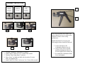
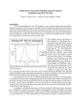
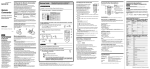
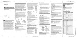
Ferrule Data Chart for Bel-Stewart Ferrule Hand Tool
Cable
Dia.
±.005
.125
.135
.145
.155
.165
.175
.185
.195
.205
.215
.225
.235
.245
.255
.255
.265
Ferrule
Hand Tool
Part Number Part Number
Ferrule Crimp Inserts
Ram
Stationary
Insert p/n
Insert p/n
2912515-01
2912516-01
2912520-01
2912521-01
2912525-01
2912526-01
2912530-01
2912531-01
2912535-01
2912536-01
2912535-01
2912582-01
2912536-01
2912583-01
F-210-205
F-235-205-L
F-270-205
F-270-205
F-300-275
2940211-01
Locator Plate Complete Ass'y.
Part Number
Part Number
2912517-01
2912518-01
2912519-01
2912522-01
2912523-01
2912524-01
2912527-01
2912528-01
2912529-01
2912532-01
2912533-01
2912534-01
2912537-01
2912538-01
2912540-01*
2912584-01
2912501-01
2912502-01
2912503-01
2912504-01
2912505-01
2912506-01
2912507-01
2912508-01
2912509-01
2912510-01
2912511-01
2912512-01
2912513-01
2912514-01
2912539-01
2912585-01
NOTE:
1. If cable diameter falls in between sizes
shown, round up to next .005 increment.
2. ( * ) at part #2912540-01 = 4mm hex nut; no
Locator Plate needed.
Bel-Stewart Connector
Ferrule Hand Tool Instructions
P/N 2940211-01
Manual #290005 – Rev. A2
Bel-Stewart Connector
11118 Susquehanna Trail South
Glen Rock, PA 17327-9199
(717) 235-7512
ASSEMBLY INSTRUCTIONS
Stationary
Crimp Insert
29125xx-01
(See chart on
back page)
Locator Plate
29125xx-01
(See chart on
back page)
Ram
Insert
29125xx-01
(See chart on
back page)
A
B
1
2
3
This tool incorporates an eccentric axle
and an adjustment wheel to adjust and recalibrate to ensure correct crimp
performance.
Should adjustment be necessary, the
following procedure should be followed:
4
1.
2.
3.
4.
5
Position “Stationary Crimp Insert” as shown.
Install “Insert” with screw. Use 2.5mm Allen wrench.
Position “Ram Crimp Insert” as shown.
Place “Insert” on hand tool label side & position “Locator
Plate” on opposite side.
5. Install “Insert” & “Plate” with screw. Use 2.5mm Allen wrench.
1. Loosen and remove the
Combination Head screw (A).
2. Using a screw driver, turn the
numbered adjustment wheel to
the next higher/lower number (B).
3. Re-install the Combination Head
Screw and tighten.