1
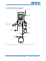
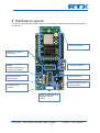
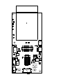
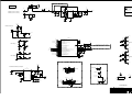
RTX41xx
Wireless Sensor Application
Board (WSAB)
Variants covered by this document:
RTX4100-WSAB
RTX4140-WSAB
User Guide
WSAB
[UG6]
User Guide – Wi-Fi Sensor Application Board (WSAB)
1
RTX41xx – Wi-Fi Module
CONTENT
1
Introduction ............................................................................................................................................ 3
1.1
General Description .................................................................................................................................. 3
1.2
Module variants covered by this document ............................................................................................. 3
1.3
Document History ..................................................................................................................................... 3
1.4
SW/HW Version ........................................................................................................................................ 3
1.5
Document References .............................................................................................................................. 3
2
Features .................................................................................................................................................. 4
3
WSAB Block Diagram .............................................................................................................................. 5
4
Hardware Layout .................................................................................................................................... 6
5
Power Supply .......................................................................................................................................... 7
5.1
Battery Powered ....................................................................................................................................... 7
5.1.1
Low Voltage Power Supply Configuration (Default configuration: 2-cell) .................................... 7
5.1.2
Direct Power Supply Configuration (3-cell) ................................................................................... 7
5.2
External Power .......................................................................................................................................... 7
6
Antenna Configuration ............................................................................................................................ 8
7
RTX41xx Module Connections ................................................................................................................. 9
8
Expansion-/Debug-connector ............................................................................................................... 10
9
Current Profile Measurements .............................................................................................................. 11
10
Board Documentation ........................................................................................................................... 12
11
Abbreviations ....................................................................................................................................... 15
12
Liability Disclaimer ................................................................................................................................ 16
User Guide – Wi-Fi Sensor Application Board (WSAB)
2
RTX41xx – Wi-Fi Module
1 Introduction
1.1 General Description
The RTX41xx (RTX4100 or RTX4140) Wi-Fi Module is a small form-factor, single stream,
802.11b/g/n Wi-Fi module with on-board low power application processor. It is targeted
at applications that send infrequent data packets over the network. Typically, 802.11
applications addressed by a RTX41xx module will place a priority on low power
consumption, ease of development, and system integration.
This document serves as a manual for the Wi-Fi Sensor Application Board (WSAB). The
WSAB is as a carrier board for the RTX41xx module to enable the user with a hardware
platform for evaluation, application software development and rapid application hardware
prototyping.
1.2 Module variants covered by this document
This document covers Wireless Sensor Application Boards (WSABs) based on both the
RTX4100 and RTX4140 WiFi modules (RTX4100-WSAB and RTX4140-WSAB).
1.3 Document History
V1.3 Added RTX4140
TM
2013-06-06
V1.2 Updated references
TM
2013-02-19
V1.1 Updated schematics
TM
2012-10-29
V1.0 Official release
TM
2012-07-09
Disclaimer: This document can be subject to change without prior notice.
1.4 SW/HW Version
This document is applicable for the following versions.
WSAB version V3RA
1.5 Document References
[DS1]. RTX4100_Datasheet_DS1.pdf.
[DS2]. RTX4140_Datasheet_DS2.pdf.
[UG1]. RTX4100_User_Guide_Module_Evaluation_UG1.pdf.
[UG3]. RTX4100_User_Guide_Application_Development_UG3.pdf.
[UG7]. RTX4100_User_Guide_WSAB_Dock_UG7.pdf.
User Guide – Wi-Fi Sensor Application Board (WSAB)
3
RTX41xx – Wi-Fi Module
2 Features
The Wi-Fi Sensor Application Board includes the following features.
RTX41xx module: The RTX41xx Wi-Fi Module small form-factor, single stream,
802.11b/g/n Wi-Fi module with on-board low power application processor.
Two push buttons: Two push buttons readable from RTX41xx pin. Can be used
for application user interface and development.
Dual color LED (Red/Green): LED controllable by RTX41xx pin. Can be used for
application user interface and development
External sensor solder points: Connection point for external resistive
transducer, connected to RTX41xx ADC and analog comparator inputs. Can be
used for connection of light sensor photo diode, NTC resistor etc.
MEMS (Micro Electro-Machanical System): 3-axis accelerometer and 3-axis
compass. Can be used to implement mechanical sensor and positioning
applications.
2x14 pin expansion-/debug-connector:
Expansion connector, with all
RTX41xx IO’s available (except pin 29), for adding customized application add-on
boards. Can be used for adding new sensor devices, power supplies etc. The
connector also serves as a connection to the USB controller cable used by the
EVK, see reference ([UG1]) . The connector also enables the WSAB to be placed in
the WSAB Docking Station, enabling a full development environment, see
reference ([UG7]).
Power supply: The power supply supports multible battery options as well as a
lab supply for development.
Current sensing resistor: A resistor in the ground path of the external power
supply enables characterization of the current profile of the application simply
using an oscilloscope.
Small form factor: 25x53mm (25x59mm including RTX4100 module)
User Guide – Wi-Fi Sensor Application Board (WSAB)
4
RTX41xx – Wi-Fi Module
3 WSAB Block Diagram
Option for external U.fl
antenna
RTX41xx module
Option for external
antenna via edge
connector
e
MEMS
3-axis accelerometer and
3-axis compas
Expansion-/
debugconnector
Push buttons
Red/Green LED
DC/DC
step-up
(for 2cell)
External sensor
solderpoints
Switch to select between
battery power or external
power via the expansion
connector
Current sense
resistor
Battery terminals
Power supply, Battery
pack or lab supply
Figur 1 WSAB blockdiagram, see section 6 for alternative antenna options
User Guide – Wi-Fi Sensor Application Board (WSAB)
5
RTX41xx – Wi-Fi Module
4 Hardware Layout
The layout of the WSAB is shown below. See detailed component placing and schematics
in chapter 0.
RTX41xx module
Expansion-/debugconnector
MEMS
3-axis accelerometer
and 3-axis compas
Two push buttons
External sensor
solderpoints
LED Red/Green
DC/DC stepup (for 2cell operation)
Current sense
resistor
Battery terminals and
supply selection
switch
User Guide – Wi-Fi Sensor Application Board (WSAB)
6
RTX41xx – Wi-Fi Module
5 Power Supply
The board supports battery power or external power. The two sources are selected by a
switch SW3, see component drawing in section 10.
In all power supply configurations the operating voltage requirements stated in the
RTX4100 module datasheet must be respected, see ([DS1]).
5.1 Battery Powered
With SW3 set to BAT the battery terminals BAT+ and BAT- supplies the board from the
batteries inserted in the battery compartment. BAT+ is the positive supply connection,
and BAT- is the negative supply connection.
The board can be configured in two power supply configurations which are described in
the following two sections. The WSAB is delivered in low voltage power supply
configuration (also refered to as 2-cell).
5.1.1 Low Voltage Power Supply Configuration (Default configuration: 2cell)
The low voltage power supply configuration supplies parts of the internal module directly
(VCC1) from the battery and other parts from the DC/DC step-up converter (VCC2)
implemented on the WSAB. The minimum input voltage in this configuration is 2.1V.
Recommended battery configurations include but are not limited to:
2x AAA alkaline (Vnom=2x1.5V)
2x AA alkaline (Vnom=2x1.5V)
5.1.2 Direct Power Supply Configuration (3-cell)
In the direct power supply configuration the battery terminals are supplying the module
directly on both module supplies VCC1 and VCC2.
Recommended battery configurations include but are not limited to:
3x AAA alkaline (Vnom=3x1.5V)
3x AA alkaline (Vnom=3x1.5V)
1x Li-ion rechargeable batteries (Vnom=3.7V)
To use the direct power supply configuration the following modifications are needed :
Un-mount R8
Move zero ohm size 0402 resistor from position R18 to R17
see component drawing in in section 10.
5.2 External Power
With SW3 set to EXT the board is supplied from the Expansion connector, this setting
should be used when the board should be powered from the WSAB Docking Station, see
reference ([UG7]).
User Guide – Wi-Fi Sensor Application Board (WSAB)
7
RTX41xx – Wi-Fi Module
6 Antenna Configuration
The RTX4100 module has an integrated antenna and an option for external antennas on
either a U.fl coaxial connector or an edge connector. The module is in its default
configuration set to use the integrated antenna.
How to change the antenna configuration between internal and external antenna is
described in the figure below.
A number of 2.4GHz WiFi antennas using the U.FL connector are available from different
vendors.
Integrated antenna (RTX41xx-IN)
External antenna (U.FL) (RTX41xx-EX)
Mount 3.3 nH chip inductor 0402 (Murata
LQG15HS3N3S02x) in above marked
position to enable the internal antenna.
This is the default configuration of the
module hardware.
Mount 0 ohm resistor size 0402 in above
marked position to enable U.FL antenna
connector.
External antenna (Edge connector)
(RTX4100-EC)
U.FL connector type:
Manufacturer: Amphenol
Order number: A-1JB
(empty)
Mount 0 ohm resistor size 0402 in above
marked position to enable the external
edge connector.
User Guide – Wi-Fi Sensor Application Board (WSAB)
8
RTX41xx – Wi-Fi Module
7 RTX41xx Module Connections
The table below shows the RTX4100 module pin connections on the WSAB and their
intended function. All module pins (except pin29) are available on the expansion
connector, see section 8. For additional information please see the RTX4100 and
RTX4140 datasheets, reference ([DS1]) and ([DS2]).
Module
Type
Module
WSAB function
Pin no.
pin name
1
2
3
4
GND
I/O
I/O
VCC2
GND
PA0
PA1
VCC2
5
6
7
GND
VCC1
O
GND
VCC1
VIO
8
I/O
PA3/PC1
9
I/O
PA4/PC0
10
11
12
13
14
15
I/O
I/O
GND
I
I/O
I/O
PB7
PB8
GND
RESETn
PB12
PB13
16
17
18
19
I/O
GND
I/O
I/O
PB14
GND
PD5
PC6
20
I/O
PC7
21
22
23
24
25
I/O
I/O
I/O
I/O
I/O
PC5/PB11
PC4/PD4
PC2
PC3
PF0
26
I/O
PF1
GND
I2C_SDA, for MEMS (IC3)
I2C_SCL, for MEMS (IC3)
Supplied by +3V5 output from DC/DC stepup (2-cell)
Can be supplied from VBAT+ (3-cell)
See section 5.1
GND
Battery supply input VBAT+
Used as.
-Reference for resistive sensor
-Supply for MEMS
-Pull up for DBG_SWDIO
US1_RX
UART_RX signal used for eg. CoLA application
download and debugging via USB virtual COM port.
US1_TX
UART_TX signal used for eg. CoLA application
download and debugging via USB virtual COM port.
Unused
Unused
GND
Unused
INT1 for MEMS (IC3)
Enable signal for DC/DC stepup (used in 2-cell
configuration, see section 5.1)
INT2 for MEMS (IC3)
GND
Input from push button SW1
LEU1_TX
Low energy UART_TX signal used for terminal demo
application via USB virtual COM port
LEU1_RX
Low energy UART_RX signal used for terminal demo
application via USB virtual COM port
DRDY for MEMS (IC3)
ADC0_CH4, ADC input for external sensor
Output for Red LED (D3)
Input from push button SW2
DBG_SWCLK, advanced debug interface clock
(requires purchase of RTX2040 Unity-II debugger)
DBG_SWDIO, advanced debug interface data IO
(requires purchase of RTX2040 Unity-II debugger)
User Guide – Wi-Fi Sensor Application Board (WSAB)
9
RTX41xx – Wi-Fi Module
27
28
29
30
I/O
GND
I/O
GND
PF2
GND
ANT
GND
Output for Green LED (D3)
GND
Unused
GND
8 Expansion-/Debug-connector
The expansion connector, with all RTX41xx IO’s available, can be used for adding
customized application add-on boards. eg. adding new sensor devices, power supplies
etc. The connector also serves as the connection to the WSAB Docking Station and the
terminal cable supplied with the EVK, see application development guide ([UG3]). The
below table shows the pinout of the expansion-/debug-connector.
J6 Pin
no.
Type
Module pin name
WSAB function
1
2
3
4
5
6
7
8
9
10
11
12
O
I/O
I/O
I/O
I/O
I/O
GND
I/O
I/O
I/O
I/O
GND
RESETn
PA0
PB12
PA1
PB8
PA3/PC1
GND
PA4/PC0
PB13
PB7
PB14
GND
13
14
I/O
I/O
PC5/PB11
PC4/PD4
See section 7
See section 7
See section 7
See section 7
See section 7
See section 7
See section 7
See section 7
See section 7
See section 7
See section 7
AGND
Analog ground may be used as reference for
RTX4100 analog I/O’s
See section 7
See section 7
J5 Pin
no.
Type
Module pin name
WSAB function
1
Power
VIO
2
Power
VCC2(*)
3
4
5
6
7
8
9
10
11
I/O
I/O
I/O
I/O
I/O
I/O
I/O
I/O
Power
PD5
PF2
PF1
PF0
PC3
PC2
PC7
PC6
VDD_EFM
VIO reference voltage.
+3V5
Step up voltage
See section 7
See section 7
See section 7
See section 7
See section 7
See section 7
See section 7
See section 7
VEXT
Supply input from WSAB Docking Station. Set
SW 3 in position EXT to use this supply for the
WSAB.
12
13
GND
Power
GND
VBAT- negative battery terminal
User Guide – Wi-Fi Sensor Application Board (WSAB)
10
RTX41xx – Wi-Fi Module
14
Power
VBAT+ positive battery terminal
(*) Only valid when WSAB is configured for 2-cell operation. 2-cell operation is the
default configuration.
9 Current Profile Measurements
The current sensing resistor (R7=0,1 Ohm) is placed in the ground path of the battery
terminals. This provides the option of characterizing the current profile of the application
simply by using an oscilloscope. Measurements can be done between J2 solder points
using a 1x probe. Connect the probe ground to the square pad of J2 and the probe tip to
the round pad of J2. A momentary current of 100mA will translate to -10mV on the
oscilloscope. Therefore the signal should be inverted in the oscilloscope channel setup.
The measurements can be used to profile or watch the active current consumption when
developing and testing applications. Due to the low value of the resistor the
measurements are only valid in active states with Wi-Fi activity. Sleep currents are too
low to measure using the current sensing resistor, and should be done by other means.
User Guide – Wi-Fi Sensor Application Board (WSAB)
11
RTX41xx – Wi-Fi Module
10 Board Documentation
User Guide – Wi-Fi Sensor Application Board (WSAB)
12
RTX41xx – Wi-Fi Module
IC5
Z100
Z100
C10
R17
IC5
C16
R18
R18
C16
R17
C10
R6
R6
R14
R14
R15
R15
R11
R13
R11
R13
C9
IC3
R27
R27
J6
1
C18
R26
R4
R4
C5
C5
C21
R19
R21
C15
C15 R21 R19 C21
R22
R22
C20
C20
R12
R12
D3
D3
J5 L1
R3
R3
C3
C4 IC2
R8 C2
R20
R20
C3
R1
R1
IC2
C4
R16
R16
J5
C7
C6
1
C8
R10
R9
R9 R26
R10
C8 C7 C6
R25
R24
C18
R24
C19
C19
SW2
R28
R28 C9
R25
TP10
SW1
SW1
IC3 J6 SW2
TP10
R5
R5
C1
C1
C17
C17
R7
R7
J2
L1
R23
J1
R8
C2
J1 R23
J2 BAT- SW3 BAT+
R2
R2
BAT-
BAT+
SW3
Z101
Z101
SW3
VEXT
R8=0R0 when using 2xAAA batteries
R8=N.M. when using 3xAAA batteries
Z1
3
1
C17
N.M.
R8
2
BAT+
BAT0R1 1%
PGND
MODE
6
EN
1
NM.
J2
FB
BAT
3
VBAT2
1
VOUT
PB13_X
10
+3V5
AGND
CDD
CP
F0
9
C20
68p
R5
4
R12
C4
N.M.
R2
R7
LX
4u7
C2
10u
1M2
0R0
VD
TP4
2xAAA (2.0V to 3.0V)
3xAAA (3.0V to 4.5V)
This schematic contain versions.
To view the appropriate values:
-Select Parts, -> Ctrl-A
-Rightclick -> Visibility
-Check Value
-Check Value-Version
IC2
XC9131F05CDR-G
L1
C5
N.M.
91K 1%
TP14
TP17
2
VBAT+
CAUTION
TP15
Batteryholder
2468
VD
C3
22u
Current version: V1-2cell
Must be changed seperately on
each page
0R0
7
R20
8
15K 1%
5
11
C1
470n
56K
R19
R22
Resitive sensor
N.M.
VDD_EFM
C21
N.M.
J1
NM.
1
2
R21
N.M.
R23
PC4/PD4
0R0
C15
220n
PB13_X
SW1
SKRELHE010
C19
N.M.
23
24
22
TP1
PC2
PC3
PC4/PD4
PC6/LEU1_TX
PC7/LEU1_RX
R4
AR
TP2
PF0/DBG_SWCLK
PF1/DBG_SWDIO
PF2
D3-B
CG
18
25
26
27
0R0
C14
N.M.
PB14
RESET
PB12/DAC0_OUT1/LETIMO0_OUT1
PB13/HFXTAL_P/LEU0_TX
PB14/HFXTAL_N/LEU0_RX
SUPPLY_1
PC2/ACMP0_CH2/US2_TX
SUPPLY_2
PC3/ACMP0_CH3/US2_RX
PC4/ACMP0_CH4/LETIM0_OUT0/PCNT1_S0IN/ US2_CLK
VIO
PD4/ADC0_CH4/LEU0_TX
PC5/ACMP0_CH5/LETIM0_OUT1/PCNT1_S1IN/ US2_CS
PB11/DAC0_OUT0/LETIMO0_OUT0
PC6/ACMP0_CH6/LEU1_TX/I2C0_SDA
PC7/ACMP0_CH7/LEU1_RX/I2C0_SCL
PD5/ADC0_CH5/LEU0_RX
GND
GND
GND
GND
PF0/LETIM0_OUT0/DBG_SWCLK
PF1/LETIM0_OUT1/DBG_SWDIO
PF2/ACMP1_O/DBG_SWO
13
R17
RESET
N.M.
VD
6
2xAAA batteries: R17=N.M. R18=0R0
3xAAA batteries: R17=0R0. R18=N.M.
+3V5
R18 0R0 VD
4
PB14_X
7
VDD_EFM
C10
N.M.
C16
N.M.
PB7_X
1
5
12
17
PB7
AGND
X1
NM.
R3
AG
PF2
270R
SML-521MUW
R15
PB8_X
Development interface signals
VDD_EFM
PC6/LEU1_TX
PC7/LEU1_RX
SETP
GND
SETC
SDA
SCL
8
10
11
RESERVED
RESERVED
RESERVED
INT1
INT2
TP7
TP11
13
DRDY
7
3
2
5
4
PB12
0R0
PB14_X
0R0
PCB1
Z100
Fiducial Mark
Z101
Fiducial Mark
81902713
VDD_EFM
R27
R26
CAUTION
PF0/DBG_SWCLK
PF1/DBG_SWDIO
PA0
PA1
PD5
PF1/DBG_SWDIO
PC3
PC7/LEU1_RX
VEXT
VBAT-
J5
2x7pol
1
3
5
7
9
11
13
2
4
6
8
10
12
14
1K0
12
C8
22n
C6
10u
PA4/PC0/US1_TX
PA3/PC1/US1_RX
10K
0R0
C7
100n
PB13_X
PB14_X
PC5/PB11
10K
R10
9
14
1
PA0
PA1
PA3/PC1/US1_RX
PA4/PC0/US1_TX
PB7_X
AGND
PC4/PD4
+3V5
R1
C9
4u7
VDD
VDD_IO
2
4
6
8
10
12
14
TP8
TP12
C1
R9
6
1
3
5
7
9
11
13
RESET
PB12
PB8_X
IC3
LSM303DLHCTR
TP5
TP6
J6
2x7pol
0R0
R16
3D accelerometer/compas
PC5/PB11
Optional LFXTAL
PB8
Expansion connectors
R28
Optional HFXTAL
0R0
User LED's
PD5
PC2
1K0
SML-521MUW
19
20
PB13
X2
NM.
VBAT+
C12
N.M.
CR
21
PC5/PB11
D3-A
10
11
14
15
16
28
29
30
0R0
PB12
PB13
PB14
PD5
GND
ANT
GND
PA3/TIM0_CDTI0
PC1/ACMP0_CH1/PCNT0_S1IN/US1_RX
PA4/TIM0_CDTI1
PC0/ACMP0_CH0/PCNT0_S0IN/US1_TX
PB7/LFXTAL_P/US1_CLK
PB8/LFXTAL_N/US1_CS
0R0
PB7
PB8
1K0
9
PA0/TIM0_CC0/I2C_SDA
PA1/TIM0_CC1/I2C_SCL/CMU_CLK1
R13
R25
8
R14
PA4/PC0/US1_TX
User keys
2
3
C11
N.M.
PA3/PC1/US1_RX
R6
PA0
PA1
PC3
C18
N.M.
N.M.
R24
SW2
1K0
SKRELHE010
C13
N.M.
IC5
RTX4100-2-IN
R11
AGND
VDD_EFM
PF2
PF0/DBG_SWCLK
PC2
PC6/LEU1_TX
PCB WSAB wireless sensor application board V3
TP3
TP10
VBAT+
TP16
Confidential
PROJECT
Wifi Sensor Application Board
VER
3
TITLE
MAIN
REV
A
DATE
120613
FILENAME
SHEET:
REF
WSAB_V3_RA.sch
1
OF
1
TM
11 Abbreviations
The following abbreviations are used in this document:
API
BSP
CoLA
GPIO
MCU
RTOS
UART
WEP
Wi-Fi
WPA
WPS
Application Programming Interface
Board Support Package
Co-Located Application
General Purpose Input/Output
Micro Controller Unit
Real-Time Operating System
Universal Asynchronous Receiver/Transmitter
Wired Equivalent Privacy
Wireless Fidelity
Wi-Fi Protected Access
Wi-Fi Protected Setup
User Guide – Wi-Fi Sensor Application Board (WSAB)
15
RTX41xx – Wi-Fi Module
12 Liability Disclaimer
General
This document and the information contained, is property of RTX A/S, Denmark.
Unauthorized copying is not allowed. The information in this document is believed to be
correct at the time of writing. RTX A/S reserves the right at any time to change said
content, circuitry and specifications.
Information contained in this document is subject to change without notice. RTX makes
no warranty of any kind with regard to this material, including, but not limited to, the
implied warranties of merchantability and fitness for a particular purpose. RTX shall not
be liable for errors contained herein or for incidental or consequential damages in
connection with the furnishings, performance, or use of this material.
Warranty
This product is warranted against defects in material and Workman ship for a period of
one year from date of shipment. During the warranty period, RTX will at its option, either
repair or replace products, which prove to be defective. For warranty service or repair,
this product must be returned to a service facility designated by RTX. Buyer shall prepay
shipping charges to RTX and RTX shall pay shipping charges, duties, and taxes for
products returned to RTX from another country. RTX warrants that its software and
firmware designated by RTX for use with a module will execute its programming
instructions when properly installed on that instrument. RTX does not warrant that the
operation of the product or firmware will be uninterrupted or error free.
Limitation of Warranty
The foregoing warranty shall not apply to defects resulting from improper or inadequate
maintenance by Buyer, Buyer-supplied software or interfacing, unauthorized modification
or misuse, operation outside of the environmental specifications for the product, or
improper site preparation or maintenance.
NO OTHER WARRANTY IS EXPRESSED OR IMPLIED.
RTX SPECIFICALLY DISCLAIMS THE IMPLIED WARRANTIES OF MERCHANTABILITY AND
FITNESS FOR A PARTICULAR PURPOSE.
User Guide – Wi-Fi Sensor Application Board (WSAB)
16
RTX41xx – Wi-Fi Module


![RTX4100 Wi-Fi Module User Guide WSAB Docking Station [UG7]](http://vs1.manualzilla.com/store/data/006886306_1-a44ab0f4a9043ebd3739376f36e6f1b4-150x150.png)