1
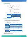
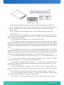
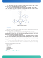
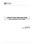
» Kontron User’s Guide «
KSSDP-VA
Document Revision 1.0
All not approved entries are marked!
This page intentionally left blank
www.kontron.com
1. General Description
Kontron KSSDP Professional series SSD is a high reliability and performance design
solid state storage device to improve customers’ data storage experience by providing
faster data transfer speed and less access time. It uses SLC & MLC NAND flash memories
chips as storage media which gives the better solution against shock and vibration problem
than traditional hard disk drive, also KSSDP-VA series provide customized function modular
options for special applications including industry wide operating temperature, data security
and data encryption.
2. Features
-
PATA interface
2.5 inch form factor
Capacity range 16G - 256G
128M DDR Cache
Stable and Sustained performance output
High random read / write transfer rate
Advanced wear-leveling
Building ECC
Advanced bad block management and flash memory management
Extreme reliability and endurance
F/W upgradeable
3. Customization Option
- Former factor
- Storage capacity
- Data Security Functions
Data Fast Clear
Data Sanitization
DoD 5220.22-M
NSA 130-2
AR 380-19
AFSSI 5020
Navso P5239-26
IRIG-106
Destructive Data Erase
- Full Disk Encryption (AES128bits)
- Operating Temperature Extension
Normal Temp : 0℃ to 70℃
Industrial Temp : – 40℃ to 80℃
- Conformal Coating
- BGA Underfill
- MIL-STD-810 compliance report
4. Physical Dimension
Parameters
Value
Unit
Length
100.2 +/-0.3
mm
Width
69.8 +/-0.3
mm
Height
9.5 +/-0.3
mm
Weigh
80 (Max.)
g
5. Product Specification
5.1 Interface
The interface of Kontron P10P Series complies with the ATA-100.
Transfer Mode:
PIO: 0,1,2,3,4
UDMA: 0,1,2,3,4,5
5.2 Capacity
Capacity
16G
32G
64G
Total Bytes
16,000,000,000
32,000,000,000
64,000,000,000
Cylinders
16383
16383
16383
Heads
16
16
16
Sectors
63
63
63
5.3 Performance
5.3.1 Data Transfer Rate
Data Transfer Rate
Sustained .Read
Sustained Write
Unit
Sustained
85
80
MB/S
Test Setup : Intel E420 + 1G DDR2 + ASUS P5KSE Main Board
OS: Windows XP SP2
Benchmark Software: HD TACH 3.01
www.kontron.com
5.3.2 IOPS
IOPS ( IO operation per second )
Access Type
512B
4K
Random Read
7000
4600
Random Write
630
350
Sequential Read
11000
6200
Sequential Write
12000
8400
Test Setup : Intel E420 + 1G DDRS + ASUS P5K SE Main Board
OS: Windows XP SP2
Benchmarking software: IO Meter 2006.07.27
5.3.3 Access Time
Random access time : 0.1msec
Test Setup : Intel Core Due E8400 + 2G DDRS + ASUS P5BSE Main Board
OS: Windows XP SP2
Benchmarking software: HD TACH 3.0.1.0
5.4 Reliability
5.4.1 Wear-Leveling
KSSDP-VA Series SSD applies Static, and Dynamic wear leveling algorithms to endure
the NAND flash memory blocks under same wearing level.
5.4.2 ECC
Building ECC ( Error Correction Code ) correct 6bits per 528 Bytes
5.4.3 Endurance
Capacity
16G
32G
64G
Read
unlimited
unlimited
unlimited
Write
>50years@
150G/day
>50years@
300G/day
>50years@
600G/day
5.4.4 Data Retention
Data retention above 10 years @ 25C
5.4.5 MTBF
MTBF (Mean Time Between Failure) > 1,000,000 Hours
5.4.6 Bad block management
Advanced the bad block management can replace the bad blocks with reserved blocks
available automatically.
6. Electrical Specification
6.1 Pin Assignment
6.1.1 Reserved Pin Assignment
Pin A
Reserved for Option FUNC
Pin C
Reserved for Option FUNC
Pin B
Reserved for Option FUNC
Pin D
Reserved for Option FUNC
6.1.2 Signal Pin Assignment
Pin No.
Signal Definition
Pin No.
Signal Definition
1
RESET
2
GND
3
DD7
4
DD8
5
DD6
6
DD9
7
DD5
8
DD10
9
DD4
10
DD11
11
DD3
12
DD12
13
DD2
14
DD13
15
DD1
16
DD14
17
DD0
18
DD15
19
GND
20
removed
21
DMARQ
22
GND
23
DIOW:STOP
24
GND
25
DIOR:HDMARDY:
26
GND
27
IORDY:DDMARDY:DSTORBE
28
CSEL
29
DMACK
30
GND
31
INTRQ
32
LOCS16
33
DA1
34
PDIAG:CBLID
35
DA0
36
DA2
37
CS0
38
CS1
39
DASP/ Indicator Pin for data purge
operating status
40
GND
41
+5V
42
+5V
43
GND
44
NC
6.2 Power Voltage
VDC 5V +/- 5%
6.3 Power Consumption
Status
Max Power Consumption
Unit
Idle
< 1.5
W
Operating
<3
W
7. Data Purge Function
Kontron Data Purge is an embedded security function which was designed to meet the
needs of data security concerned applications such as defense and other special purposes.
Data Purge delivers reliable hi-speed data clear and sanitization with user friendly interface
and auto power failure resume function.
www.kontron.com
The time required to purge a SSD depends on the actual purge mode invoked by the
user and the flash memory type / flash memory configuration of the drive. A list of typical
purge times of SSD is listed in Table 1.
SSD
Clear Speed
Clear Time
Sanitization Speed Sanitization Time
32G MLC
5GB/sec
6 Secs
60MB/s
8 Mins
64G MLC
10GB/sec
6 Secs
100MB/s
10 Mins
32G SLC
6GB/sec
5 Secs
120MB/s
4 Mins
64G SLC
6GB/sec
10 Secs
120MB/s
8 Mins
7.1 Operating Principle
Clear
Clearing is the processing of erasing data on the media. In a NAND flash based SSD,
this is done by executing a block-by-block erase with verify. Data Purge implements the
block-by-block erase on entire physical flash blocks including user data area and reserved
area for FW, spare and logical to physical mapping table. This results in all the data on
media were erased and unrecoverable.
As soon as the Purge was triggered, SSD will cut off the signals transfer between
Host system and SSD, stop receiving new ATA commands, and force to interrupt on-going
ATA commands; and then SSD will execute block-by-block erase until all blocks in user
data area were erased.
After user data area erased, if “sanitization” mode were invoked, SSD will follow
the sanitization procedure to overwrite/fill the user data area by pre-defined pattern; if
“Clear” mode were invoked, SSD will continue to execute erase on all vendor reserved
data area, logical to physical mapping table, and firmware area. The SSD will be set back
to “blank” with no function after “clear”.
Sanitization
Sanitizing is the process of declassifying the drive by executing an unrecoverable
removal of fall data on the media. In a NAND Flash based SSD, this initiates a sequence
of block-by-block erase, pattern write and pattern verify operations designed to eliminate
any trace of the original data.
KSSDP-VA provides customer standard sanitization procedure by overwriting “1” to
all user data area after block-by-block erase. The SSD will be set back to factory default
with full functions after “Sanitization”.
7.2 User Interface and Operating Guide
Trigger Method
The Data Purge can be triggered by various methods software trigger, hardware
trigger or method combined software and hardware. A successful software trigger would
depend on a functional platform which might be limited by hardware, OS, and application
software used in Host system, and it is hard to guarantee the normal function of host
system in emergency;
Kontron designs a system-independence in-drive hardware mechanism to deliver a
simple and reliable trigger method for Data Purge function.
User Interface and Definition
Pin Definition - PATA
A dedicated 2 reserved pins connector was provided for trigger switch in KSSDP-VA:
Pin A : Trigger Pin, 3.3V input, internal resistor pull-up, output was protected by series
resistor. Pin A and Pin B are combined as a normal open type switch for purge trigger;
Pin D : GND
Pin 39 : Indicator Pin for operating status,3.3V LVCMOS output for LED driving.
Operating Guide
The Purge function was triggered by closing and holding Pin A and Pin D switch for
a given time. And LED between Pin 39 and Pin D(or GND)can show operating status –
ready, operating and completion.
(1)Purge Ready, after SSD power on, the indictor LED is ON;
(2)Pre-Trigger, closing and holding the trigger switch, SSD will go to pre-trigger
status, LED will flicker at 1Hz; if user releasing the switch in pre-trigger stage, the SSD will
go back to (1); SSD will be triggered to Data Clear mode by holding the switch for 2 seconds
;and SSD will be triggered to Sanitization mode by holding the switch for 4 seconds or
more.;
(3)User Data Erase, as soon as the commands were triggered, SSD will cut off the
signals transfer between Host and SSD, stop receiving new ATA commands, and force to
interrupt on-going ATA commands; and then SSD will execute block-by-block erase until all
blocks in user data area were erased, then go ( 4 ), if sudden power fail, jump to ( 3a )
(4)Purge Mode Judgment, Data Clear mode, go(5); Data Sanitization mode,go
(6);
(5)Erase reserved block,logical to physical mapping table, Firmware. If sudden
power failed then go(5a);After all erase operations, go(7);
(6)Overwrite / fill erased user data area by “1”,LED will flick,and one LED on/ff
cycle means 1GB data area have been overwritten/filled. If sudden power fail then go(6a);
After overwrite / filling, go(7);
(7)Data Purge complete,LED will be ON;SSD is set back to factory default in offline, 10 seconds power-off should be conducted before restart the Host system and put SSD
in use.
(3a)LED ON; until internal backup power used up. Power On again,jump to (3b);
(3b)Auto resume and ready to continue. If sudden power fail again; if SSD is ready
then jump to (3); if the SSD is not ready, then jump to (3a);
(5a)LED ON;until internal backup power used up. Power On again,jump to (5b)
www.kontron.com
(5b)Auto resume and ready to continue. If sudden power fail again; if SSD is ready
then jump to 53); if the SSD is not ready, then jump to (5a);;
(6a)LED On; until internal backup power used up. Power On again,jump to ( 6b);
(6b) Auto resume and ready to continue. If sudden power fail again; if SSD is ready
then jump to (6); if the SSD is not ready, then jump to (6a);
Status Changing Diagram
7.3 Options
Data Purge is a flexible modular design, and can provide following options which can
be customized to meet various applications.
(1)Trigger Time, can be changed more or less, default setting is 2 seconds;
(2)Trigger Mode Setting, the default Data Clear Trigger is defined as holding switch
for 2 seconds, and holding time over 4 seconds is defined as Data Sanitization. The actual
settings can be adjusted by customer requirement.
(3)An in-drive back-up power system have been provided as default, so the SSD
can keep working well and auto resume during and after sudden power fail. Also Kontron
provides customer option to enhance the back-up power by adding more extra back-up
power which is strong enough to support the energy used for erase entire disk area in
emergency.
(4)Kontron can provide pre-defined pattern for data overwrite / fill, default setting
is “1”, by customer requirement, the pattern can be defined to comply with third party
standards in following list or customer spec.
DoD 5220.22-M
NSA 130-2
AR 380-19
AFSSI 5020
Navso P5239-26
RIG-106
8. Environmental Specification
8.1 Temperature
Status
Operating
Non-Operating
Temperature
0 to +70℃
Extended Temp -40℃ to +80℃
-40℃-+80℃
Extended Temp -45 ℃to +85℃
Unit
Degree C
Degree C
8.2 Humidity
Parameter
Humidity
Unit
Operating
5-90
%
Parameter
Force
Unit
Operating
2000
G
Status
Parameter
Unit
Operating
20G Peak 20-15KHZ with 3 Axis
G
Status
Parameter
Unit
Operating
-1000 - 15000
feet
8.3 Shock
8.4 Vibration
8.5 Altitude
9. Production ordering information
9.1 Ordering Part.-NO.
Article
Part.-No.
Description
KSSDP-VA
KSSD-P-M000032-01A
2.5’’ IDE compatible 32GByte SSD with MLC Flash
KSSDP-VA
KSSD-P-M000064-01A
2.5’’ IDE compatible 64GByte SSD with MLC Flash
KSSDP-VA
KSSD-P-M000128-01A
2.5’’ IDE compatible 128GByte SSD with MLC Flash
KSSDP-VA
KSSD-P-M000256-01A
2.5’’ IDE compatible 256GByte SSD with MLC Flash
KSSDP-VA
KSSD-P-M000032-01C
KSSDP-VA
KSSD-P-M000064-01C
KSSDP-VA
KSSD-P-M000128-01C
KSSDP-VA
KSSD-P-M000256-01C
KSSDP-VA
KSSD-P-M000016-02C
KSSDP-VA
KSSD-P-M000032-02C
KSSDP-VA
KSSD-P-M000064-02C
KSSDP-VA
KSSD-P-M000128-02C
2.5’’ IDE compatible 32GByte SSD with MLC Flash,
temperature -40℃ to 70℃
2.5’’ IDE compatible 64GByte SSD with MLC Flash,
temperature -40℃ to 70℃
2.5’’ IDE compatible 128GByte SSD with MLC Flash,
temperature -40℃ to 70℃
2.5’’ IDE compatible 256GByte SSD with MLC Flash,
temperature -40 to 70℃
2.5’’ IDE compatible 16GByte SSD with SLC Flash,
temperature -40℃ to 85℃
2.5’’ IDE compatible 32GByte SSD with SLC Flash,
temperature -40℃ to 85℃
2.5’’ IDE compatible 64GByte SSD with SLC Flash,
temperature -40℃ to 85℃
2.5’’ IDE compatible 128GByte SSD with SLC Flash,
temperature -40℃ to 85℃
extended
extended
extended
extended
extended
extended
extended
extended
9.2 Product function code
www.kontron.com
1. For updates or additional information about Kontron products, contact your nearest
Kontron office.
2. Kontron products are not intended for use in life support, critical care, medical,
safety equipment, or similar applications where products failure could result in loss of life
or personal or physical harm, or any military or defense application, or any governmental
procurement to which special terms or provisions may apply.
* Kontron reserves the right to change products or specification without notice.
Copyright Notice:
Copyright © 2009 by Kontron. All rights reserved. Information contained in this
document, including but not limited to any instructions, descriptions and product
specifications, is proprietary to Kontron. and shall not be modified, used, copied, reproduced
or disclosed in whole or in part, in any form or by any means, electronic or mechanical, for
any purpose, without the written consent of Kontron