1
M12M GPS Receiver User’s Guide
DOCUMENT PREPARED BY I-LOTUS CORPOARATION PTE.LTD.,
SINGAPORE
Information in this document is subject to change without notice and does not
represent a commitment on the part of i-Lotus Corporation Pte.Ltd. The software
described in this document is furnished under a license agreement. The software
may be used or copied only in accordance with the terms of the agreement.
i-Lotus Corporation Pte.Ltd. All rights reserved, No part of this publication may be
reproduced, transmitted, stored in a retrieval system, or translated into any
language in any means, without the written permission of i-Lotus.
and i-Lotus are registered trademarks of i-Lotus Corporation Pte.Ltd.
© 2006, i-Lotus Corporation Pte.Ltd. Printed in Singapore.
If you need help or have any questions regarding i-Lotus GPS products, contact
yo ur i-lotus customer representative.
i-Lotus is an Equal Employment Opportunity/Affirmative Action Employer
Table of Contents
CHAPTER 1 – INTRODUCTION
1
OVERVIEW
M12M Positioning Receiver
M12M Timing Receiver
2
2
2
PRODUCT HIGHLIGHTS
3
APPLICATIONS
4
LIMITED WARRANTY ON I-LOTUS GPS PRODUCTS
How to Get Warranty Service
5
6
CHAPTER 2 - NAVSTAR GPS OVERVIEW
7
ABOUT THE GPS NAVIGATION MESSAGE
Space Segment
Ground Control Segment
User Segment
Additional Information Sources
8
8
8
8
10
CHAPTER 3 - RECEIVER DESCRIPTIONS
11
OVERVIEW
Memory Backup
Operating With a Backup Source
Operating Without a Backup Source
12
13
13
14
Antenna Drive and Protection Circuitry
15
Active Antenna Configuration
17
M12M Receiver Electrical Connections
17
M12M Nominal Voltage and Current Ranges
Main Power
Backup Battery (Externally applied backup power)
18
18
18
M12M ONCORE RECEIVER TECHNICAL CHARACTERISTICS
20
M12M TIMING RECEIVER TECHNICAL CHARACTERISTICS
21
RF Jamming Immunity (M12M Timing Receiver Only)
22
Adaptive Tracking Loops (M12M Timing Receiver Only)
22
Time RAIM Algorithm (M12M Timing Receiver Only)
22
i-Lotus GPS Products - M12M User's Guide Revision 1.0 01May06
Automatic Site Survey (M12M Timing Receiver Only)
100PPS Output (M12M Timing Receiver Only)
Mean Time Between Failure (MTBF)
24
24
25
Receiver Module Installation
Electrostatic Precautions
Electromagnetic Considerations
RF Shielding
Thermal Considerations
Grounding Considerations
PCB Mounting Hardware
25
25
26
26
26
26
27
System Integration
Interface Protocols
Serial Input/Output
Binary Format
Exclusive-Or (XOR) Checksum creation
Millisecond to Degree Conversion
NMEA Protocol Support
NMEA Commands to the Receiver
RTCM Differential GPS Support
Input/Output Processing Time
29
29
29
30
34
35
36
36
38
39
DATA LATENCY
Position Data Latency
Velocity Data Latency
Time Data Latency
40
41
41
41
ONE PULSE PER SECOND (1PPS) TIMING
Measurement Epoch Timing
Output Data Timing Relative To Measurement Epoch
1PPS Cable Delay Correction and 1PPS Offset (M12M Timing Receiver Only)
41
41
42
43
OPERATIONAL CONSIDERATIONS
Time to First Fix (TTFF)
First Time On
Initialization
Shut Down
Received Carrier to Noise Density Ratio (C/No)
43
44
44
44
45
46
SETTING UP RECEIVERS FOR SPECIFIC APPLICATIONS
M12M as a Standard Autonomous Positioning Receiver
M12M as a Positioning Receiver Using Differential Corrections
M12M as a Differential Base Station
M12M as a Precision Timing Receiver
47
47
47
48
48
CHAPTER 4 – ANTENNA DESCRIPTIONS
51
M12M Antenna Type I
Antenna Description
Antenna Gain Pattern
RF Connectors/Cables Information
52
52
54
57
i-Lotus GPS Products - M12M User's Guide Revision 1.0 01May06
Antenna Placement
Antenna System RF Parameter Considerations
58
59
M12M Antenna Type II
Antenna Description
Antenna Gain Pattern
Installation Precautions
Antenna Mounting
Antenna in Extreme Weather and Environmental Conditions
Antenna Cable and Connector Requirements
Environmental Tests
61
61
63
64
64
64
65
66
CHAPTER 5 - I/O COMMANDS
68
OVERVIEW
69
I/O COMMAND LIST INDEX BY BINARY COMMAND
70
SATELLITE MASK ANGLE COMMAND (@@Ag)
73
SATELLITE IGNORE LIST MESSAGE (@@Am)
75
POSITION LOCK PARAMETERS MESSAGE (@@AM)
77
MARINE FILTER SELECT COMMAND (@@AN)
79
DATUM SELECT COMMAND (@@Ao)
81
RTCM PORT BAUD RATE SELECT COMMAND (@@AO)
83
DEFINE USER DATUM MESSAGE (@@Ap)
85
PULSE MODE SELECT COMMAND (@@AP)
87
IONOSPHERIC CORRECTION SELECT COMMAND (@@Aq)
89
POSITION FILTER SELECT COMMAND (@@AQ)
91
POSITION HOLD PARAMETERS MESSAGE (@@As)
93
POSITION LOCK SELECT MESSAGE (@@AS)
95
TIME CORRECTION SELECT (@@Aw)
97
1PPS TIME OFFSET COMMAND (@@Ay)
99
1PPS CABLE DELAY CORRECTION COMMAND (@@Az)
101
VISIBLE SATELLITE DATA MESSAGE (@@Bb)
103
ALMANAC STATUS MESSAGE (@@Bd)
105
i-Lotus GPS Products - M12M User's Guide Revision 1.0 01May06
ALMANAC DATA REQUEST (@@Be)
107
EPHEMERIS DATA INPUT (@@Bf)
109
PSEUDO-RANGE CORRECTION OUTPUT REQUEST (@@Bh)
111
LEAP SECOND STATUS MESSAGE (@@Bj)
113
UTC OFFSET OUTPUT MESSAGE (@@Bo)
115
REQUEST UTC/IONOSPHERIC DATA (@@Bp)
117
ALMANAC DATA INPUT (@@Cb)
119
PSEUDO-RANGE CORRECTION DATA INPUT (@@Ce)
121
SET TO DEFAULTS COMMAND (@@Cf)
123
NMEA PROTOCOL SELECT (@@Ci)
125
RECEIVER ID (@@Cj)
127
UTC/IONOSPHERIC DATA INPUT [Response to @@Bp or @@Co]
129
ASCII POSITION MESSAGE (@@Eq)
133
COMBINED POSITION MESSAGE (@@Ga)
137
COMBINED TIME MESSAGE (@@Gb)
139
1PPS CONTROL MESSAGE (@@Gc)
143
POSITION CONTROL MESSAGE (@@Gd)
145
TIME RAIM SELECT MESSAGE (@@Ge)
147
TIME RAIM ALARM MESSAGE (@@Gf)
149
LEAP SECOND PENDING MESSAGE (@@Gj)
151
VEHICLE ID (@@Gk)
153
12 CHANNEL POSITION/STATUS/DATA MESSAGE (@@Ha)
155
12 CHANNEL SHORT POSITION MESSAGE (@@Hb)
161
12 CHANNEL TIME RAIM STATUS MESSAGE (@@Hn)
165
INVERSE DIFFERENTIAL WITH PSEUDORANGE OUTPUT (@@Hr)
167
12 CHANNEL SELF-TEST MESSAGE (@@Ia)
173
i-Lotus GPS Products - M12M User's Guide Revision 1.0 01May06
SYSTEM POWER-ON FAILURE
175
NMEA GPGGA MESSAGE
177
GPGLL (NMEA GEOGRAPHIC LATITUDE AND LONGITUDE)
181
GPGSA (GPS DOP AND ACTIVE SATELLITES)
183
GPGSV (NMEA GPS SATELLITES IN VIEW)
185
GPRMC (NMEA RECOMMENDED MINIMUM SPECIFIC GPS/TRANSIT DATA)
187
GPVTG (NMEA TRACK MADE GOOD AND GROUND SPEED)
189
GPZDA (NMEA TIME AND DATE)
191
SWITCH I/O FORMAT TO BINARY
193
APPENDIX 1 – GPS TERMINOLOGY
196
i-Lotus GPS Products - M12M User's Guide Revision 1.0 01May06
This page intentionally left blank.
i-Lotus GPS Products - M12M User's Guide Revision 1.0 01May06
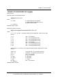
Chapter 1 - Introduction
Chapter 1 – INTRODUCTION
CHAPTER SUMMARY
Refer to this chapter for the following:
•
An introduction to GPS and the M12M Oncore receivers
•
A limited warranty for the receivers
1
i-Lotus GPS Products - M12M User's Guide Revision 1.0 01May06
Chapter 1 - Introduction
OVERVIEW
Nearly a decade of Global Positioning System (GPS) experience, combined with world-class
expertise in semiconductor products and communications development, the production of the
M12M GPS receiver modules are more compact and lightweight than ever before. Each channel
independently tracks both code and carrier for the superior performance required in today's GPS
user environment. Specifically designed for embedded applications, the M12M, when combined
with our range of active micro-strip patch antennas, affords the engineer new freedom in bringing
GPS technology to the most demanding Original Equipment Manufacturer (OEM) applications.
M12M receiver offerings include:
M12M Positioning Receiver
The M12M Oncore positioning receiver is a12-channel design offering one of the fastest Time to
First Fix (TTFF) specifications in the industry, and split second reacquisition times.
M12M Timing Receiver
The M12M timing receiver is a variant of the M12M positioning receiver, and its highly optimized
firmware makes it one of the most capable timing receivers on the market. Standard features
include precise, programmable, one-pulse-per-second (1PPS) or 100 pulse-per-second (100PPS)
outputs and features T-RAIM integrity monitoring algorithm.
2
i-Lotus GPS Products - M12M User's Guide Revision 1.0 01May06
Chapter 1 - Introduction
PRODUCT HIGHLIGHTS
Features present on all M12M receivers include the following:
•
12-channel parallel receiver design
•
Code plus carrier tracking (carrier-aided tracking)
•
Position filtering
•
Antenna current sense circuitry
•
Operation from +2.85 to +3.15 Vdc regulated power
•
3V CMOS/TTL serial interface to host equipment
•
3-dimensional positioning within 25 meters, SEP (with Selective Availability [SA]
disabled)
•
Latitude, longitude, height, velocity, heading, time, and satellite status information
transmitted at user determined rates (continuously or polled)
•
Straight 10-pin power/data header for low-profile flat mounting against host circuit board.
An optional right angle header is available for vertical PWA mounting.
•
Optional on-board Lithium battery
Additional features specific to the M12M positioning receiver include:
•
Support for inverse differential GPS operation
•
RTCM differential GPS support using second serial port
•
User selectable NMEA 0183 output
•
User controlled velocity filter
Additional features specific to the M12M timing receiver include:
•
Precise 1PPS output (+/- 25 ns accuracy) w/o sawtooth correction
•
Selectable 100PPS output
•
Time RAIM (Time-Receiver Autonomous Integrity Monitoring) algorithm for checking
timing solution integrity
•
Automatic site survey
3
i-Lotus GPS Products - M12M User's Guide Revision 1.0 01May06
Chapter 1 - Introduction
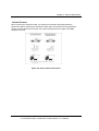
APPLICATIONS
Considering that 24-hour, all weather, worldwide coverage is fundamental to GPS positioning and
navigation, it is easy to envision a broad range of applications and a large community of GPS
users. Applications include the following:
•
Automobile Navigation
•
Aircraft Navigation
•
Land Navigation
•
Marine Navigation
•
Emergency Calling
•
Theft Recovery
•
Telematics
•
Fleet Tracking
•
Routing Systems
•
Rail Management
•
Asset Management
•
Emergency Search and Rescue
•
Utility Services
•
Precise Time Measurement
•
Frequency Stabilization
•
Network Synchronization
•
Surveying and Mapping
•
Exploration
4
i-Lotus GPS Products - M12M User's Guide Revision 1.0 01May06
Chapter 1 - Introduction
LIMITED WARRANTY ON I-LOTUS GPS PRODUCTS
What This Warranty Covers And For How Long
i-Lotus Corporation Pte. Ltd. ("i-Lotus") warrants its Global Positioning System (GPS) Products
("Product") against defects on material and workmanship under normal use and service for a
period of twelve (12) months from Product's in-service date, but in no event longer than eighteen
(18) months from initial shipment of the Product.
i-Lotus, at its option, will at no charge either repair, exchange, or replace this Product during the
warranty period provided it is returned in accordance with the terms of this warranty. Replaced
parts or boards are warranted for the balance of the original applicable warranty period. All
replaced parts or Product shall become the property of i-Lotus. Any repairs not covered by this
warranty will be charged at the cost of replaced parts plus the i-Lotus hourly labor rate current at
that time.
This express limited warranty is extended by i-Lotus to the original end user purchaser only and is
not assignable or transferable to any other party. This is the complete warranty for Products
manufactured by i-Lotus. i-Lotus does not warrant the installation, maintenance or service of the
Product.
i-Lotus cannot be responsible in any way for any ancillary equipment not furnished by i-Lotus,
which is attached to or used in connection with i-Lotus 's GPS Products, or for operation of the
Product with any ancillary equipment and all such equipment is expressly excluded from this
warranty.
The Global Positioning System is operated and supported by the U.S. Department of Defense
and is made available for civilian use solely at its discretion. The Global Positioning System is
subject to degradation of position, velocity, and time accuracies by the Department of Defense. Idoes not warrant or control Global Positioning System availability or performance.
This warranty applies around the world.
What This Warranty Does Not Cover
(a)
Defects or damage resulting from use of the Product in other than its normal and
customary manner.
(b)
Defects or damage from misuse, accident or neglect.
(c)
Defects or damage from improper testing, operation, maintenance, installation, alteration,
modification or adjustment.
(d)
Defects or damage due to lightning or other electrical discharge.
(e)
Product disassembled or repaired in such a manner as to adversely affect performance
or prevent adequate inspection and testing to verify any warranty claim.
5
i-Lotus GPS Products - M12M User's Guide Revision 1.0 01May06
Chapter 1 - Introduction
(f)
(g)
Product which has had the serial number removed or made illegible.
Freight costs to the repair depot.
How to Get Warranty Service
To receive warranty service, contact your Oncore reseller.
General Provisions
This warranty sets forth the full extent of i-Lotus's responsibility regarding the Product. Repair,
replacement, or refund of the purchase price, at i-Lotus's option, is the exclusive remedy.
THIS WARRANTY IS GIVEN IN LIEU OF ALL OTHER EXPRESS WARRANTIES. IMPLIED
WARRANTIES, INCLUDING WITHOUT LIMITATION IMPLIED WARRANTIES OF
MERCHANTABILITY AND FITNESS FOR A PARTICULAR PURPOSE, ARE LIMITED TO THE
DURATION OF THIS LIMITED WARRANTY. IN NO EVENT SHALL I-LOTUS BE LIABLE FOR
DAMAGES IN EXCESS OF THE PURCHASE PRICE OF THE PRODUCT, FOR ANY LOSS OF
USE, LOSS OF TIME, INCONVENIENCE, COMMERCIAL LOSS, LOST PROFITS OR SAVINGS
OR OTHER INCIDENTAL, SPECIAL OR CONSEQUENTIAL DAMAGES ARISING OUT OF THE
INSTALLATION, USE, OR INABILITY TO USE SUCH PRODUCT, TO THE FULL EXTENT
SUCH MAY BE DISCLAIMED BY LAW.
6
i-Lotus GPS Products - M12M User's Guide Revision 1.0 01May06
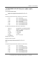
Chapter 2 - Receiver Descriptions
Chapter 2 - NAVSTAR GPS OVERVIEW
CHAPTER SUMMARY
Refer to this chapter for the following:
•
A description of the NAVSTAR GPS segments
•
An explanation of the GPS navigation message
•
A list of available public GPS information services
7
i-Lotus GPS Products - M12M User's Guide Revision 1.0 01May06
Chapter 2 - Receiver Descriptions
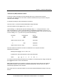
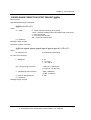
ABOUT THE GPS NAVIGATION MESSAGE
The NAVigation Satellite Timing and Ranging (NAVSTAR) Global Positioning System is an all
weather, radio based, satellite navigation system that enables users to accurately determine 3dimensional position, velocity, and time worldwide. The overall system consists of three major
segments: the space segment, the ground control segment, and the user segment.
Space Segment
The space segment is a constellation of satellites operating in 12-hour orbits at an altitude of
20,183 km (10,898 m). The constellation is composed of 24 satellites in six orbital planes, each
plane equally spaced about the equator and inclined at 55 degrees.
Ground Control Segment
The ground control segment consists of a master control center and a number of widely
separated monitoring stations. The ground control network tracks the satellites, precisely
determines their orbits, and periodically uploads almanac, ephemeris, and other system data to
all satellites for retransmission to the user segment.
User Segment
The user segment is the collection of all GPS user receivers (such as your Oncore GPS
Receiver) and their support equipment. The receiver determines position by a process known as
passive multi-lateration. More simply, the GPS receiver's position is determined by the geometric
intersection of several simultaneously observed ranges (satellite to receiver distances) from
satellites with known coordinates in space.
The receiver measures the transmission time required for a satellite signal to reach the receiver.
Transit time is determined using code correlation techniques. The actual measurement is a
unique time shift for which the code sequence transmitted by the satellite correlates with an
identical code generated in the tracking receiver. The receiver code is shifted until maximum
correlation between the two codes is achieved. This time shift multiplied by the speed of light is
the receiver's measure of the range to the satellite. This measurement includes various
propagation delays, as well as satellite and receiver clock errors. Since the measurement is not a
true geometric range, it is known as a pseudo-range. The receiver processes these pseudo-range
measurements along with the received ephemeris data (satellite orbit data) to determine the
user's three-dimensional position. A minimum of four pseudo-range observations are required to
mathematically solve for four unknown receiver parameters (i.e., latitude, longitude, altitude, and
clock offset). If one of these parameters is known (altitude, for example) then only three satellite
pseudo-range observations are required, and thus only three satellites need to be tracked.
8
i-Lotus GPS Products - M12M User's Guide Revision 1.0 01May06
Chapter 2 - Receiver Descriptions
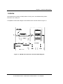
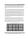
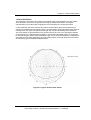
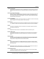
Figure 2.1 NAVSTAR GPS Segments
The GPS navigation message is the data supplied to the user from a satellite. Signals are
transmitted at two L-band frequencies, L1 and L2, to permit corrections to be made for
ionospheric delays in signal propagation time in dual frequency receivers. The L1 carrier is
modulated with a 10.23 MHz precise (P-code) ranging signal and a 1.023 MHz coarse acquisition
(C/A code) ranging signal.
NOTE: The P-Code is intended for military use
and is only available to authorized users
using special receivers.
The P and C/A codes are pseudo-random-noise (PRN) codes in phase quadrature. The L2 signal
is modulated with the P-code only. Both the L1 and L2 signals are also continuously modulated
with a data stream at 50 bits per second. The P-code is a PRN sequence with a period of 38(+)
weeks. The C/A code is a shorter PRN sequence of 1023 bits having a period of one millisecond.
9
i-Lotus GPS Products - M12M User's Guide Revision 1.0 01May06
Chapter 2 - Receiver Descriptions
The navigation message consists of a 50 bit per second data stream containing information
enabling the receiver to perform the computations required for successful navigation. Each
satellite has its own unique C/A code that provides satellite identification for acquisition and
tracking by the user.
There are several GPS related sites on the World Wide Web that are excellent sources of
information about GPS and the current status of the satellites. Several are listed below:
Additional Information Sources
U.S. Coast Guard Navigation Center - Civilian GPS service notices, general system
information, and GPS outage reporting:
http://www.navcen.uscg.gov/gps/default.htm
U.S. Naval Observatory - USNO time service information and links to USNO timing and other
useful sites:
http://tycho.usno.navy.mil/
NTP Homepage - Information on using GPS receivers for precision network timing in both
Windows and Linux environments.
http://www.ntp.org
NAVSTAR GPS Homepage - General GPS information and links to other useful GPS sites:
http://gps.losangeles.af.mil/
National Marine Electronics Association (NMEA) - For information on the NMEA protocol
specification:
http://www.nmea.org/
Radio Technical Commission Marine (RTCM) - For information on the RTCM specification for
DGPS corrections:
http://www.rtcm.org
General GPS Information
http://www.gpsworld.com/gpsworld
Helpful equations, code snippets, and other useful information:
http://www.colorado.edu/geography/gcraft/notes/gps/gps_f.html
10
i-Lotus GPS Products - M12M User's Guide Revision 1.0 01May06
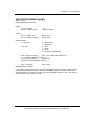
Chapter 2 - Receiver Descriptions
CHAPTER 3 - RECEIVER DESCRIPTIONS
CHAPTER SUMMARY
Refer to this chapter for the following:
•
A simplified functional description of the operation of the M12M Oncore receiver
•
Antenna power and gain requirements
•
Physical size and electrical connections of the M12M Oncore receiver
•
M12M Oncore receiver technical characteristics and operating features
•
M12M installation precautions and mounting considerations
•
Binary and NMEA interface protocol descriptions
•
Operational details of the M12M Oncore receiver
11
i-Lotus GPS Products - M12M User's Guide Revision 1.0 01May06
Chapter 2 - Receiver Descriptions
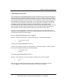
OVERVIEW
The M12M Oncore receiver provides position, velocity, time, and satellite tracking status
information via a serial port.
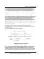
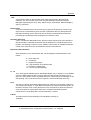
A simplified functional block diagram of the M12M receiver is shown below in Figure 3.1.
Figure 3.1: M12M Oncore Receiver Functional Block Diagram
12
i-Lotus GPS Products - M12M User's Guide Revision 1.0 01May06
Chapter 2 - Receiver Descriptions
The M12M Oncore receiver is capable of tracking twelve satellites simultaneously. The module
receives the L1 GPS signal (1575.42 MHz) from the antenna and operates off the
coarse/acquisition (C/A) code tracking. The code tracking is carrier aided. Time recovery
capability is inherent in the architecture.
The L1 band signals transmitted from GPS satellites are typically collected, filtered, and amplified
by microstrip patch antennas such as the Type I or Type II. Signals from the antenna module are
then routed to the RF signal processing section of the M12M via a single coaxial interconnecting
cable. This interconnecting cable also provides bias power for the low-noise-amplifier (LNA) in the
antenna. The is capable of providing the antenna with voltages from 2.5-5.5V at currents up to
80mA.
The RF signal processing section of the M12M printed circuit board (PCB) contains the required
circuitry for down-converting the GPS signals received from the antenna module. The resulting
intermediate frequency (IF) signal is then passed to the twelve channel code and carrier
correlator section of the M12M where a single, high speed analog-to-digital (A/D) converter
converts the IF signal to a digital sequence prior to channel separation. This digitized IF signal is
then routed to the digital signal processor where the signal is split into twelve parallel channels for
signal detection, code correlation, carrier tracking, and filtering.
The processed signals are synchronously routed to the position microprocessor (MPU) section.
This section controls the receiver operating modes, decodes and processes satellite data, and
the pseudo-range and delta range measurements used to compute position, velocity, and time. In
addition, the position processor section contains the inverted serial interface.
Memory Backup
Frequently, backup batteries are used with M12M receivers. Use of a backup battery is not
mandatory, but can be useful for saving setup information and increasing the speed of satellite
acquisition and fix determination when the receiver is powered up after a period of inactivity.
M12M receivers may be ordered with or without a rechargeable lithium cell onboard, use an
external backup voltage source, or operate without any backup source whatsoever.
Battery equipped M12M receivers are fitted with 5 mAh cells, sufficient for 2 weeks to a month of
backup time, depending on temperature. Note that these cells ARE rechargeable types, and in
order to charge them the receiver MUST be powered up. A factory fresh receiver should be
allowed to run for 24-36 hours to provide the battery with an initial full charge.
Operating With a Backup Source
If employed, the backup source keeps the RAM and the Real-Time Clock (RTC) in the receiver
alive, saving setup and status information. Time, Date, Last Calculated Position, Almanac, and
Ephemeris information, along with receiver specific parameters and output message configuration
are all saved, making resumption of operation once main power is restored essentially automatic.
In this “Warm Start” scenario the power comes back on, the receiver looks to the RTC to see how
much time has elapsed since power was removed, calculates which satellites should be visible
using the stored almanac information, and then proceeds to develop fix information, outputting
data in the same formats that were active when power was removed.
13
i-Lotus GPS Products - M12M User's Guide Revision 1.0 01May06
Chapter 2 - Receiver Descriptions
Operating Without a Backup Source
Without any backup power none of the setup information mentioned above is available to the
receiver upon restart. The receiver must now perform a “Cold Start”, where position, time, and
almanac information are not available. Note that this is not a serious problem, but Time To First
Fix (TTFF) will be somewhat longer than if the information had been available.
The main thing the system designer must keep in mind is that a receiver coming up in a Cold
Start scenario is defaulted to Binary protocol, and NO MESSAGES are ACTIVE. The receiver is
running through its normal housekeeping routines, developing new fix data, etc., but it will not
send any of this data out of the serial port until it is requested.
If the receiver is being used as part of a larger system where the user has access to the
receiver’s serial port through application software such as WinOncore12, the user can simply use
the software to reinitialize the receiver into the desired mode.
Embedded developers have to be careful since they typically do not have direct access to the
receiver’s serial port. In this case the best thing to do is to ASSUME that the receiver will always
wake up in a defaulted condition and include code in the application software to initialize the
receiver every time power is cycled. This code may be as simple as merely directing the receiver
to output a standard Binary Position/Status/Data message (@@Ha for instance), or may possibly
involve uploading a stored almanac, switching the receiver over to NMEA mode and initializing
the desired NMEA strings. No matter, the effect is still the same: if the receiver wakes up with all
setup information intact, there’s no harm done, the initialization commands merely reinforce the
configuration data already present in RAM. If the receiver powers up in the defaulted mode the
initialization code ensures that the receiver operates in the manner intended.
NOTE: Receivers fitted with onboard batteries CANNOT
utilize external backup power.
Although there are many reasons for not using a receiver fitted with a battery, the three instances
that come up most often are:
1. Remote systems that are expected to run unattended for long periods of time. The
most common example of this type of situation is in the timing receivers used to keep
CDMA cell sites synchronized. These systems are expected to operate for 10-20
years in remote areas and having to replace batteries every 5 years or so would
present a severe maintenance problem.
2. Operation in continuous high temperatures. Although M12M receiver is rated for
operation at +85oC, the lithium cells have a service ceiling of +60oC.
3.
Operation at low duty cycles. A common example of this type of application is
oceanographic buoys. These might typically turn on the M12M once a day for a few
minutes, get a fix, and then power the receiver back down. Over time the result is that
the battery is never allowed to charge up between power cycles and slowly
discharges. A better choice in this situation is to use an external primary battery with
sufficient capacity for the entire deployment, or use of a “SuperCap” or
“UltraCapacitor” as a backup power source. Since these can be charged up in a
matter of seconds while the receiver is getting it’s daily position fix, loss of capacity
over time is not an issue.
14
i-Lotus GPS Products - M12M User's Guide Revision 1.0 01May06
Chapter 2 - Receiver Descriptions
Antenna Drive and Protection Circuitry
The M12M is capable of detecting the presence of an antenna. The receiver utilizes an antenna
sense circuit that can detect under current (open condition), over current (shorted or exceeding
maximum receiver limits), or a valid antenna connection. The M12M is designed to provide up to
80 mA of current via the antenna power supply circuit. The circuit contains short protection and a
means for detecting over current and open circuit conditions of the connection between it and the
antenna. This allows the user a degree of confidence that the antenna is connected properly and
is drawing current. This feature can eliminate hours of troubleshooting, especially in a new
installation.
The antenna power supply circuit consists of a current sense resistor, two rail-to-rail output
operational amplifiers, a pass transistor and a voltage divider to set the upper and lower limits of
the under current and over current thresholds. The operational amplifiers compare the voltage
developed across the current sense resistor with these thresholds. If the antenna is drawing 15
mA or more, the first operational amplifier will produce a logic level to the digital circuits,
indicating that an antenna is attached. If the signal is absent, indicating an under current
condition, an alarm bit is set to alert the user. Having this alarm bit high does not prevent the
receiver from operating, and may in fact be high all the time when utilizing an antenna with low
current draw, or when supplying the antenna with power through an external source using a
bias-T.
The over current detection circuit operates in a similar manner. When the voltage drop across the
current sense resistor is equal to the over current threshold (set at about 90 mA at room
temperature) the output of the sense amplifier starts shutting down the pass transistor. The
receiver will automatically fold-back the antenna feed current to approximately 45mA until the
fault is cleared. As with the undercurrent sensor, a logic level is provided to the digital circuits to
trigger an alarm bit that indicates the over-current condition.
The antenna sense circuit was designed to operate with the Antenna Type I and Antenna Type II
GPS antennas, therefore non-quantified antennas may exceed the threshold limits as listed
below:
Under current detect @ 25°C:
Good indication:
Undercurrent indication:
Over current detect @ 25°C:
greater than 15 mA
less than 15 mA
80 mA maximum for normal operation
NOTE: An external power source such as a
bias-T must be used if the antenna circuit power
requirement exceeds the upper limit.
15
i-Lotus GPS Products - M12M User's Guide Revision 1.0 01May06
Chapter 2 - Receiver Descriptions
The antenna status information is output in the following I/O messages:
•
•
•
@@Ha(12 Channel Position/Status/Data Message)
@@Hb (12 Channel Short Position Message)
@@Ia (12 Channel Self-Test Message).
NOTE: Detection of an under current situation will
not prevent the from operating. The will
continue to operate normally, but will raise the error
flag in the three messages, indicating a possible
antenna problem.
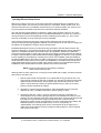
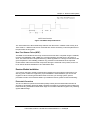
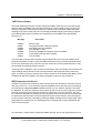
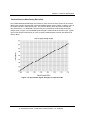
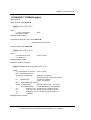
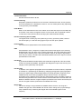
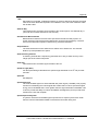
A chart of the typical output voltage vs. the load current is shown below in figure 3.2. Note that
there is some drop to the output voltage as higher currents are drawn due to IR losses across the
current sense resistor and pass transistor. The system engineer should consider this drop if the
coax run to the antenna is going to be long, and/or the gain of the antenna being used is
adversely affected by lowered input voltage. Note that the can accept any voltage from +2.5 to
+5.5 Vdc on the antenna bias pin (Pin 9.)
Figure 3.2
antenna drive circuit performance
16
i-Lotus GPS Products - M12M User's Guide Revision 1.0 01May06
Chapter 2 - Receiver Descriptions
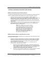
Active Antenna Configuration
The recommended external gain (antenna gain minus cable and connector losses) for the M12M
is 10 to 50 dB. A typical antenna system might have an active antenna such as the Antenna Type
I with 29 dB of gain and five meters of cable with 5 dB of loss. The net external gain would then
be 24 dB, which is well within the acceptable range. While the receiver may track satellites with
gain values outside of the recommended limits, performance may suffer and the receiver may be
more susceptible to noise and jamming from other RF sources. For more information on
antennas, refer to Chapter 4.
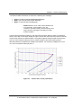
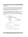
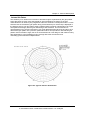
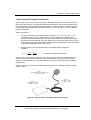
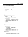
M12M Receiver Electrical Connections
The M12M receivers receive electrical power and receive/transmit I/O signals through a 10-pin
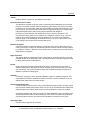
power/data connector mounted on the receiver. Figure 3.3 below illustrates the positions of both
the 10-pin header and the MMCX antenna connector.
Figure 3.3: M12M Oncore Receiver
17
i-Lotus GPS Products - M12M User's Guide Revision 1.0 01May06
Chapter 2 - Receiver Descriptions
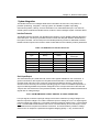
The following table lists the assigned signal connections of the M12M receiver's power/data
connector.
Table 3.1: M12M Power/Data Connector Pin Assignments
Pin #
1
2
3
4
5
6
7
8
9
10
Signal Name
TxD1
RxD1
+3V PWR
1PPS
Ground
Battery
Reserved
RTCM In
Antenna Bias
Reserved
Description
Transmit Data (3V logic)
Receive Commands (3V logic)
Regulated 3Vdc Input
1 pulse-per-second output
Signal and Power common
Optional External Backup
Not currently used
RTCM correction input
3V-5V antenna bias input
Not currently used
M12M Nominal Voltage and Current Ranges
Main Power
Voltage:
2.85V to 3.15V regulated, 50 mV peak-to-peak ripple
Current:
52 mA maximum (without antenna)
Backup Battery (Externally applied backup power)
Voltage:
2.2V to 3.2V
Current:
5 µA typical @ 2.7V and 25°C ambient temperature
Backup power retains the real-time-clock, position, satellite data, user commanded operating
modes, and message formatting.
18
i-Lotus GPS Products - M12M User's Guide Revision 1.0 01May06
Chapter 2 - Receiver Descriptions
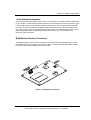
M12M ONCORE RECEIVER PRINTED CIRCUIT BOARD MECHANICAL DRAWINGS
Figure 3.4:
M12M Oncore Printed Circuit Board Layout with Straight, 0.050" [1.27mm]
Pitch, 10 Pin Data Header
19
i-Lotus GPS Products - M12M User's Guide Revision 1.0 01May06
Chapter 2 - Receiver Descriptions
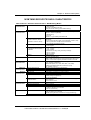
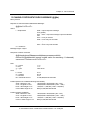
M12M ONCORE RECEIVER TECHNICAL CHARACTERISTICS
Table 3.2 Oncore Technical Characteristics – M12M Nav Model
General
Characteristics
Performance
Characteristics
Receiver Architecture
Tracking Capability
Dynamics
Acquisition Time
(Time To First Fix, TTFF)
(Tested at –40 to +85ºC)
Positioning Accuracy
Timing Accuracy
(1 Pulse Per Second, 1 PPS)
Datum
Antenna
Serial
Communication
Electrical
Characteristics
Physical
Characteristics
Antenna Requirements
Output Messages
Power Requirements
“Keep-Alive” BATT Power
Power Consumption
Dimensions
Weight
Connectors
Antenna to Receiver
Interconnection
Environmental
Characteristics
Miscellaneous
Operating Temperature
Storage Temperature
Humidity
Altitude
Standard Features
Optional Features
12 parallel channel
L1 1575.42 MHz
C/A code (1.023 MHz chip rate)
Code plus carrier tracking (carrier aided tracking)
12 simultaneous satellite vehicles
Velocity: 1000 knots (515 m/s) > 1000 knots (515 m/s); at
altitudes < 60,000 ft.(18000m)
Acceleration: 4g
3
Jerk: 5 m/s
Vibration: 7.7g per Military Standard 810E
< 15 s typical TTFF-hot (with current almanac, position, time and
ephemeris)
< 40 s typical TTFF-warm (with current almanac, position, time)
< 60 s typical TTFF-cold (No stored information)
< 1.0 s internal reacquisition (typical)
< 5 m, 1-sigma
< 10 m, 2-sigma
< 500 ns, 2-sigma
WGS-84 default
One user definable datum
Active antenna module powered by receiver module (80mA max)
10dB to 50dB external antenna gain measured at receiver input
3 Vdc or 5 Vdc antenna power provided via header connector
Latitude, longitude, height, velocity, heading, time
Binary protocol at 9600 baud
NMEA 0183 (GGA, GLL, GSA, GSV, RMC, VTG, ZDA)
Software selectable output rate (continuous or poll)
TTL interface (0 to 3 V)
Second COM port for RTCM input
2.8 to 3.3 Vdc; 50 mVp-p ripple (max)
External 2.2 Vdc to 3.2 Vdc, 5 uA typical @ 2.7 Vdc @ 25ºC
155 mW @ 3 V without antenna
40.0 x 60.0 x 13.0 mm (1.57 x 2.36 x 0.53 in.)
Receiver 12.5 g
Data/power: 10 pin (2x5) unshrouded header on 0.050 in.
centers (straight configuration)
RF: right angle MMCX
Single coaxial cable (with power on center conductor to support
active antenna)
Antenna sense circuit
-40ºC to +85ºC
-40ºC to +105ºC
95% over dry bulb range of +38ºC to +85ºC
18,000 m (60,000 ft.) maximum
> 18,000 m (60,000 ft.) for velocities < 515 m/s (1000 knots)
DGPS corrections at 9600 baud on COM 1
RTCM SC-104 input Type 1 and Type 9 messages for DGPS at
2400, 4800 or 9600 baud on COM 2
Inverse DGPS support
Lithium battery backup
20
i-Lotus GPS Products - M12M User's Guide Revision 1.0 01May06
Chapter 2 - Receiver Descriptions
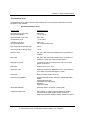
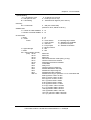
M12M TIMING RECEIVER TECHNICAL CHARACTERISTICS
Table 3.3Oncore Technical Characteristics – M12M Timing Model
General
Characteristics
Performance
Characteristics
Receiver Architecture
Tracking Capability
Dynamics
Acquisition Time
(Time To First Fix, TTFF)
(Tested at –40ºC to +85ºC)
Positioning Accuracy
Timing Accuracy
1 Pulse Per Second (PPS), or
100 PPS
Datum
Antenna
Serial
Communication
Electrical
Characteristics
Physical
Characteristics
Antenna Requirements
Output Messages
Power Requirements
“Keep-Alive” BATT Power
Power Consumption
Dimensions
Weight
Connectors
Antenna to Receiver
Interconnection
Environmental
Characteristics
Miscellaneous
Operating Temperature
Storage Temperature
Humidity
Altitude
Standard Features
Optional Features
12 parallel channel
L1 1575.42 MHz
C/A code (1.023 MHz chip rate)
Code plus carrier tracking (carrier aided tracking)
12 simultaneous satellite vehicles
Velocity: 1000 knots (515 m/s) > 1000 knots (515 m/s); at
altitudes < 60,000 ft.(18000m)
Acceleration: 4g
3
Jerk: 5 m/s
Vibration: 7.7g per Military Standard 810E
< 15 s typical TTFF-hot (with current almanac, position, time and
ephemeris)
< 40 s typical TTFF-warm (with current almanac, position, time)
< 150 s typical TTFF-cold (No stored information)
< 1.0 s internal reacquisition (typical)
< 5 m, 1-sigma
< 10 m, 2-sigma
Performance using clock granularity message:
< 2 ns, 1-sigma
< 6 ns, 6-sigma
Performance not using clock granularity message:
< 10 ns, 1-sigma
< 20 ns, 6-sigma
WGS-84 default
One user definable datum
Active antenna module powered by receiver module (80mA max)
10dB to 50dB external antenna gain measured at receiver input
3 Vdc or 5 Vdc antenna power provided via header connector
Latitude, longitude, height, velocity, heading, time
Binary protocol at 9600 baud
NMEA 0183 (GGA, GLL, GSA, GSV, RMC, VTG, ZDA)
Software selectable output rate (continuous or poll)
TTL interface (0 to 3 V)
2.8 Vdc to 3.3 Vdc; 50 mVp-p ripple (max)
External 2.2 Vdc to 3.2 Vdc, 5 uA typical @ 2.7 Vdc @ 25ºC
155 mW @ 3 V without antenna
40.0 x 60.0 x 13.0 mm (1.57 x 2.36 x 0.53 in.)
Receiver 12.5 g
Data/power: 10 pin (2x5) unshrouded header on 0.050 in.
centers (straight configuration)
RF: right angle MMCX
Single coaxial cable (with power on center conductor to support
active antenna)
Antenna sense circuit
-40ºC to +85ºC
-40ºC to +105ºC
95% over dry bulb range of +38ºC to +85ºC
18,000 m (60,000 ft.) maximum
> 18,000 m (60,000 ft.) for velocities
< 515 m/s (1000 knots)
Position hold with automatic site survey
Clock granularity error message
T-RAIM (Timing Receiver Autonomous Integrity Monitoring)
Lithium battery backup
21
i-Lotus GPS Products - M12M User's Guide Revision 1.0 01May06
Chapter 2 - Receiver Descriptions
RF Jamming Immunity (M12M Timing Receiver Only)
Many precise timing GPS installations require locating the GPS antenna at close range to other
systems. Some of these transmitters may randomly cause the GPS receiver to lose lock on
tracked satellites. This can be very disconcerting to the timing user since the system must rely on
clock coasting until the satellite signals are reacquired. Long coasting times require more
expensive oscillators for the timing electronics in order to meet system specifications for holdover
capability.
Experience has shown that receiver selectivity, or the ability to select only the GPS band of
information and reject all other signals, is an important feature for GPS receivers, especially in
cases such as those often encountered in timing applications.
Adaptive Tracking Loops (M12M Timing Receiver Only)
The jamming immunity of the M12M Oncore timing receiver is done by an innovative software
technique to further improve the immunity. The technique takes advantage of the fact that for
precise timing applications, the receiver is not moving. In mobile GPS applications, the receiver
must be able to track satellites under varying dynamics. Vehicle acceleration causes an apparent
frequency shift in the received signal due to Doppler shift. In order to track signals through
acceleration, the tracking loops are wide enough to accommodate the maximum expected vehicle
acceleration and velocity. When the receiver is stationary, the tracking loops do not need to be as
wide in order to track the satellites. In the M12M timing receiver firmware, the satellite tracking
loops are narrowed once the receiver has acquired the satellites and reached a steady state
condition. This adaptive approach allows the tracking loops to be narrowed for maximum
interference rejection while not unduly compromising the rapid startup and acquisition
characteristics of the receiver.
Test results have demonstrated that this approach is effective at providing an additional 10 dB of
jamming immunity to both in-band and out-of-band signals. The combined results of the additional
filtering and the adaptive tracking loops in the M12M Oncore combine to provide the user with a
receiver/antenna system effective at improving RF jamming immunity, thus making installation in
timing applications more flexible and robust. The status of the tracking loops (wide-band or
narrow-band) are indicated by status bits in the @@Ha and @@Hb messages.
Time RAIM Algorithm (M12M Timing Receiver Only)
Time Receiver Autonomous Integrity Monitoring (T-RAIM) is an algorithm in Oncore timing
receivers (including the M12M T) that uses redundant satellite measurements to confirm the
integrity of the timing solution. The T-RAIM approach is borrowed from the aviation community
where integrity monitoring is safety critical.
22
i-Lotus GPS Products - M12M User's Guide Revision 1.0 01May06
Chapter 2 - Receiver Descriptions
In most surveying systems and instruments, there are more measurements taken than are
required to compute the solution. The excess measurements are redundant. A system can use
redundant measurements in an averaging scheme to compute a blended solution that is more
robust and accurate than using only the minimum number of measurements required. Once a
solution is computed, the measurements can be inspected for blunders. This is the essence of TRAIM.
In order to perform precise timing, the GPS receiver position is determined and then the receiver
is put into Position-Hold mode where the receiver no longer solves for position. With the position
known, time is the only remaining unknown. When in this mode, the GPS receiver only requires
one satellite to accurately determine time. If multiple satellites are tracked, then the time solution
is based on an average of the satellite measurements. When the average solution is computed, it
is compared to each individual satellite measurement to screen for blunders. A residual is
computed for each satellite by differencing the solution average and the measurement. If there is
a bad measurement in the set, then the average will be skewed and one of the measurements
will have a large residual. If the magnitude of the residuals exceeds the expected limit, then an
alarm condition exists and the individual residuals are checked. The magnitude of each residual
is compared with the size of the expected measurement error. If the residual does not fall within a
defined confidence level of the measurement accuracy, then it is flagged as a blunder. Once a
blunder is identified, then it is removed from the solution and the solution is recomputed and
checked again for integrity.
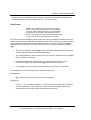
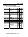
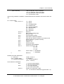
A simple analogy can be used to demonstrate the concept of blunder detection and removal: a
table is measured eight times using a tape measure. The measurements are recorded in a
notebook, but one of the measurements is recorded incorrectly. The tape measure has 2 mm
divisions, so the one-sigma (1σ) reading error is about 1 mm. This implies that 95% of the
measurements should be within 2 mm of truth. The measurements and residuals are recorded in
the table on the following page. From the residual list, it is clear that trial six was a blunder. With
the blunder removed, the average and residuals are recomputed. This time, the residuals fall
within the expected measurement accuracy. This is shown in Table 3.4 below.
Table 3.4: Blunder Detection Example
1
Measurement
(m)
9.998
Residual
(mm)
14.5
2
10.001
3
Trial
Status
New Residual (mm)
OK
2
11.5
OK
-1
9.999
13.5
OK
1
4
10.000
12.5
OK
0
5
10.002
10.5
OK
-2
6
10.100
-87.5
removed
7
9.999
13.5
OK
1
8
10.001
11.5
OK
-2
Ave
10.0125
10.000
23
i-Lotus GPS Products - M12M User's Guide Revision 1.0 01May06
Chapter 2 - Receiver Descriptions
Automatic Site Survey (M12M Timing Receiver Only)
The Automatic Site Survey mode simplifies system installation for static timing applications. This
automatic position determination algorithm is user initiated and can be deactivated at any time.
The Automatic Site Survey averages a total of 10,000 (slightly over 2 1/2 hours) valid 2D and 3D
position fixes. If the averaging process is interrupted, the averaging resumes where it left off
when tracking resumes. During averaging, bit 4 of the receiver status words in the
Position/Status/Data Messages (@@Ha and @@Hb) is set. Once the position is surveyed, the
M12M timing receiver automatically enters the Position-Hold Mode. At this point, the auto survey
flag is cleared and the normal position-hold flag is set in the receiver status byte of the @@Ha
and @@Hb messages.
Once the antenna site has been surveyed in this manner, the user can expect a 2D position error
of less than 10 meters with 95% confidence, and a 3D error of less than 20 meters with 95%
confidence.
Throughout the survey time the T-RAIM algorithm (if enabled) is active and is capable of
detecting satellite anomalies, however isolation and removal of the bad measurement is not
possible. Once the survey is completed, the T-RAIM algorithm is capable of error detection,
isolation, and removal.
Status of the Automatic Site Survey and Position-Hold Modes is retained in RAM when the
receiver is powered down if battery backup power is provided.
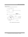
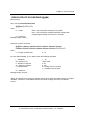
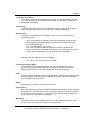
100PPS Output (M12M Timing Receiver Only)
With the M12M timing firmware, the timing output can be selected between 1PPS and 100PPS.
This is done using the Pulse Mode command (@@AP). See chapter 5 for information on the
formatting of this command. When selected, the 100PPS signal is output on the same pin as the
1PPS, and has the same accuracy and stability characteristics as the 1PPS signal. Each pulse is
approximately 2-3 ms in duration except for every hundredth pulse, which is 6-7 ms in duration to
allow logic implemented by the user to determine when the top of the second is about to occur.
The leading edge of the pulse following the long pulse corresponds to the top of the second
(referenced to UTC or GPS, depending on the Time Mode selected by the user using the @@Aw
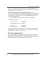
command). Figure 3.6 shows a diagram of the 100PPS output signal.
24
i-Lotus GPS Products - M12M User's Guide Revision 1.0 01May06
Chapter 2 - Receiver Descriptions
Figure 3.6 100PPS Output Waveform
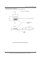
The 1PPS Offset and 1PPS Cable Delay features work the same in 100PPS mode as they do in
1PPS mode. In 100PPS mode, these commands are used to accurately control the placement of
the pulse after the long pulse.
Mean Time Between Failure (MTBF)
The MTBF for the M12M Oncore family of GPS receivers has been computed using the methods,
formulas, and database of MIL-HDBK-217 to be approximately 750,000 hours (>85 years) at
40ºC. The value has been computed assuming a static application in a benign environment at the
given temperature. This reliability prediction only provides a broad estimate of the expected
random failure rates of the electrical components during the useful life of the product, and is not
to be used as absolute indications of true field failure rates
Receiver Module Installation
Your receiver has been carefully inspected and packaged to ensure optimum performance. As
with any piece of electronic equipment, proper installation is essential before you can use the
equipment. When mounting the M12M receiver board into your housing system, special
precautions need to be considered. Before you install the receiver, please review the following:
Electrostatic Precautions
The Oncore Receiver printed circuit boards (PCBs) contain parts and assemblies sensitive to
damage by electrostatic discharge (ESD). Use ESD precautionary procedures when handling the
PCB. Grounding wristbands and anti-static bags are considered standard equipment in protecting
against ESD damage.
25
i-Lotus GPS Products - M12M User's Guide Revision 1.0 01May06
Chapter 2 - Receiver Descriptions
Electromagnetic Considerations
The Oncore receiver PC boards contain a very sensitive RF receiver; therefore you must observe
certain precautions to prevent possible interference from the host system. Because the
electromagnetic environment will vary for each OEM application, it is not possible to define exact
guidelines to assure electromagnetic compatibility. The frequency of GPS is 1.575 GHz.
Frequencies or harmonics close to the GPS frequency may interfere with the operation of the
receiver, desensitizing the performance. Symptoms include lower signal to noise values, longer
TTFFs and the inability to acquire and track signals. In cases where RF interference is suspected,
common remedies are to provide the receiver with additional RF shielding and/or moving the
antenna away from the source of the interference.
RF Shielding
The RF circuitry sections on the M12M are surrounded with an RF dam to provide some
protection against potential interference from external sources. When a design calls for the M12M
to be near or around RF sources such as radios, switching power supplies, microprocessor
clocks, etc., it is recommended that the M12M be tested in the target environment to identify
potential interference issues prior to final design. In worst-case situations, the M12M PCB may
require an additional metal shield to eliminate electromagnetic compatibility (EMC) problems.
Thermal Considerations
The receiver operating temperature range is -40°C to +85°C, and the storage temperature range
is -40°C to +105°C. Before installation, you should perform a thermal analysis of the housing
environment to ensure that temperatures do not exceed +85°C when operating (+105°C stored).
This is particularly important if air circulation in the installation site is poor, other electronics are
installed in the enclosure with the M12M, or the M12M is enclosed within a shielded container
due to electromagnetic interference (EMI) requirements.
M12M receivers fitted with onboard lithium backup batteries present a special case. Although the
receiver is rated for operation to +85C, the lithium cell has a recommended upper temperature
limit of +60C. Sustained operation at temperatures above this level may result in reduced backup
time and premature battery failure.
Grounding Considerations
The ground plane of the receiver is connected to the four mounting holes. For best performance,
it is recommended that the mounting standoffs in the application be grounded. The receiver will
still function properly if it is not grounded via the mounting holes, but the shielding may be less
effective.
26
i-Lotus GPS Products - M12M User's Guide Revision 1.0 01May06
Chapter 2 - Receiver Descriptions
PCB Mounting Hardware
The M12M Oncore PCB is normally mounted on round or hex female threaded metal standoffs
and retained with metal English or metric screws. Mounting standoffs are available in a wide
variety of materials with English or metric threads. Several sources are listed in Table 3.5. Key
points in selecting the four screws and standoffs that will mechanically hold and secure the M12M
to the application PCB are the screw sizes, screw head designs, and the diameter and length of
the standoffs.
The four holes in the M12M PCB are designed to accommodate 4-40 (English) or 2.5 or 3mm
(metric) mounting screws. It is recommended that these screws have Philips, Torx, or other head
designs that retain the installation tool in order to avoid component damage that may occur if the
tool slips out of the screw head. Recommended torque to assemble the M12M PCB to the
standoffs is 6 in-lb, with a maximum of 7 and minimum of 5 in-lb. While somewhat higher torques
can be tolerated, use of extremely high torques can possibly crack internal clads in the four-layer
M12M PCB. Washers are not required or recommended.
Standoffs should have a maximum outside diameter (OD) of .187" (4.5mm). Note that these are
standard sizes and should be easy to procure from a number of sources. Use of larger diameter
standoffs can result in damage to small surface mount components mounted in close proximity to
the mounting holes. If standoffs of the recommended diameters are not available, the next larger
available diameter may possibly be used, but fit should be carefully verified before committing to
large-scale production.
Obviously the height of the standoffs will be determined by the components that are populated on
the application PCB, especially the height of the 10-pin receptacle. See Figures 3.4, which are
outline drawings of the M12M receiver. The drawings describe the overall placement and height
of large components and connectors populated on both sides of the M12M PCB.
27
i-Lotus GPS Products - M12M User's Guide Revision 1.0 01May06
Chapter 2 - Receiver Descriptions
Table 3.5: List of Threaded Standoff Suppliers
Company Name
Keystone Electronic
Corp.
Tel: 718.956.8900
Fax: 718.956.9040
www.keyelco.com
RAF Electronics
Hardware
Tel: 203.888.2133
Fax: 203.888.9860
www.rafhdwe.com
PEM Engineering
and Manufacturing
Corp.
Tel: 215.766.8533
Fax: 215.766.0143
Part Description
Plain female or 4-40 threaded
standoffs, available in lengths
of 0.125" to 1.0"
Plain female or M2.5 and M3.0
threaded standoffs, available
in lengths from 5 to 25 mm
Plain female or 4-40 threaded
standoffs, available in lengths
of 0.125" to 1.0"
Plain female or M2.5 and M3.0
threaded standoffs, available
in lengths from 5 to 25 mm
Self clinching 4-40 female
standoffs available in lengths
from 0.25" to 1.0"
Self clinching M3.0 female
standoffs available in lengths
from 5 to 25 mm
Outside Diameter
0.187", round or hex
4.5 mm round or hex
0.187", round or hex
4.5 mm round or hex
0.165" round
4.2mm round
www.pemnet.com
28
i-Lotus GPS Products - M12M User's Guide Revision 1.0 01May06
Chapter 2 - Receiver Descriptions
System Integration
The M12M receiver is an intelligent GPS sensor intended to be used as a component in a
precision positioning, navigation, or timing system. The M12M is capable of providing
autonomous position, velocity, and time information over a standard serial port. The minimum
usable system combines the M12M receiver, antenna, and an intelligent system controller device.
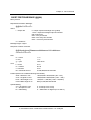
Interface Protocols
The M12M receiver has either one (M12M Timing Receiver) or two (M12M Positioning Receiver)
serial data ports. The first port provides the main control and data path between the M12M and
the system controller. The second port on the M12M positioning receiver is dedicated to RTCM
DGPS correction inputs to the receiver. Refer to table below for the interface protocol parameters.
Table 3.6: M12M Oncore Interface Protocols
Format
Binary
NMEA 0183
Type
Binary
ASCII
Direction
Port
Baud Rate
Parity
Data Bits
Start/Stop bits
In/Out
1
9600
None
8
1/1
In/Out
1
4800
None
8
1/1
RTCM SC-104
Type 1 or 9
messages
In
2
2400, 4800,9600
None
8
1/1
Serial Input/Output
The serial interface pins, RxD and TxD, are the main signals available for user connection. A
ground connection is also required to complete the serial interface. The M12M's serial port
operates under interrupt control. Incoming commands and data are stored in a buffer that is
serviced once a second by the receiver's operating program. There is no additional protection or
signal conditioning besides the protection designed into the microprocessor since the RxD and
TxD pins are connected to the microprocessor directly. TxD and RxD are standard inverted serial
signals with 3V voltage swings.
Note: THE M12M SERIAL PORTS ARE NOT 5V LOGIC COMPLIANT
For input signals, minimum input high voltage is 2V and the maximum input high voltage is 3V.
Minimum input low voltage is 0 V and the maximum input low voltage is 0.8 V. For output signals,
minimum output high voltage is 2.4 V and the maximum output low voltage is 0.5 V. This interface
is not a conventional RS-232 interface that can be connected directly to a PC serial port, an RS232 driver/receiver is required to make this connection. The driver/receiver provides a voltage
shift from the 3V outputs to a positive and negative voltage (typically +/- 8V), and also has an
29
i-Lotus GPS Products - M12M User's Guide Revision 1.0 01May06
Chapter 2 - Receiver Descriptions
inversion process in it. Most RS-232 driver/receiver integrated circuits (Maxim's MAX3232, for
example) will provide all these functions with only a +3V power supply.
Binary Format
NOTE: In the following discussion and in ensuing
areas of the manual concerned with communications
protocols, data characters without any prefixes will be
interpreted as decimal data, data beginning with ‘0x’
will be interpreted as hex data, and data beginning with
a lower case 'b' will be interpreted as binary data.
The native binary data messages used by all Oncore receivers (including the M12M) consist of a
variable number of binary characters (hex bytes). For ease of use, many Oncore users commonly
refer to these binary sequences by their ASCII equivalents. For instance, all binary messages
begin with the hex characters '0x40 0x40', which most users convert to the ASCII equivalents:
'@@'.
•
The first two characters after the '@@' header comprise the Message ID and identify the
particular structure and format of the remaining data.
•
This message data can vary from one byte to over 150 bytes, depending on the message
being transmitted or received.
•
Immediately following the message data is a single byte checksum which is the
Exclusive-Or (XOR) of all bytes after the '@@' and before the checksum).
•
The message is terminated with the Carriage Return/Line Feed pair: ‘0x0D 0x0A’.
Summarizing, every binary message has the following components:
Message Start:
@@ - (two hex 0x40's) denote the start of binary message.
Message ID:
(A.Z(a..z, A..Z) - Two ASCII characters - the first an ASCII upper-case letter, followed by
an ASCII lowercase or upper case letter. These two characters together identify the
message type and imply the correct message length and format.
30
i-Lotus GPS Products - M12M User's Guide Revision 1.0 01May06
Chapter 2 - Receiver Descriptions
Binary Data Sequence:
A variable number of bytes of binary data dependent on the command type.
Checksum:
The Exclusive-Or of all bytes after the '@@', and prior to the
checksum.
Message Terminator:
'0x0D 0x0A' - Carriage Return/Line Feed pair denoting the end of the binary message.
Almost all receiver input commands have a corresponding response message so that you can
determine whether the input command(s) have been accepted or rejected by the receiver. The
message format descriptions in Chapter 5 detail the input command and response message
formats. Information contained in the data fields is normally numeric. The interface design
assumes that the operator display is under the control of an external system data processor and
that display and message formatting code reside in its memory. This approach gives you
complete control of the display format and language.
All M12M receivers read command strings in the input buffer once per second. If a full command
has been received, the receiver operates on that command and performs the indicated function.
Input character string checks are performed on the input commands. A binary message is
considered to be valid if it began with the '@@' characters, the message is the correct length for
its type, the checksum validates, and the command is terminated with a CR/LF pair. Improperly
formatted messages are discarded.
You must take care in correctly formatting the input command. Pay particular attention to the
number of parameters and their valid ranges. An invalid message could be interpreted as a valid
unintended message. A beginning '@@', a valid checksum, a terminating carriage return/line
feed, the correct message length and valid parameter ranges are the only indicators of a valid
input command to the receiver. For multi-parameter input commands, the receiver will reject the
entire command if one of the input parameters is out of range. Once the input command is
detected, the receiver validates the message by checking the checksum byte in the message.
Input and output data fields contain binary data that can be interpreted as scaled floating point or
integer data. The field width and appropriate scale factors for each parameter are described in
the individual I/O message format descriptions. Polarity of floating point data (positive or
negative) is described via the two's complement presentation.
Input command messages can be stacked into the receiver input buffer up to the depth of the
message buffer (1200 characters long). The receiver will operate on all full messages received
during the previous one second interval and will process them in the order they are received.
Previously scheduled messages may be output before the responses to the new input
commands.
Almost all input commands have a corresponding output response message. Input commands
31
i-Lotus GPS Products - M12M User's Guide Revision 1.0 01May06
Chapter 2 - Receiver Descriptions
may be of the type that changes configuration parameters of the receiver. Examples of these
input command types include commands to change the initial position, receiver internal time and
date, satellite almanac, etc. These input commands, when received and validated by the receiver,
change the indicated parameter and result in a response message to show the new value of the
parameter that was changed. If the new value shows no change, then the input command was
either formatted improperly, or one of the input parameters was out of its valid range.
NOTE: Every change-parameter type input command (except
for the @@Ci message) has a corresponding response message
showing the configuration parameter change. To request the
current status of any current receiver parameter, simply enter an
input command with at least one parameter out of the normal range.
The response to properly formatted commands with out-of-range
parameters is to output the original unchanged value of the
parameter in the response message.
Input commands may also be of the type that enable or disable the output of data or status
messages. These output status messages include those that the external controller will use for
measuring position, velocity, and time. Status messages are output at the selected update rate
(typically, once per second) for those messages that contain position, velocity, or time, or can be
commanded to output the data one time upon request. The rate at which the data is output in the
continuous output mode is dependent on the update rate requested by the user. Table 3.7 below
shows the rates at which the data messages are output for each type of message, depending on
the setting of the continuous/polled option that is part of the input command.
Table 3.7: Binary Mode Data Message Output Rates
OUTPUT
MESSAGE TYPE
12 Channel
Position/Status/Data
ASCII Position
Message
12 Channel T-RAIM
Status**
MESSAGE ID
@@Ha
@@Eq
@@Hn
Almanac Data
@@Cb
Visible Satellite
Status
@@Bb
UTC Offset Status
@@Bo
Leap Second Status
**M12M timing receiver only
@@Gj
CONTINUOUS
(m=1..255)
At user selected
update rate
At user selected
update rate
At user selected
update rate
When new almanac
data available
When visibility status
changes
When UTC offset
available or when it
changes
POLLED
(m=0)
When requested
When requested
When requested
When requested
When requested
When requested
When requested
In cases where more than one output message is scheduled during the same one second
interval, the receiver will output all scheduled messages but will attempt to limit the total number
of bytes transmitted each second to 800 bytes. For the case of multiple output messages, if the
32
i-Lotus GPS Products - M12M User's Guide Revision 1.0 01May06
Chapter 2 - Receiver Descriptions
next message to be sent fits around the 800 byte length goal, then the message will be output.
For example, if messages totaling 758 bytes are scheduled to be sent, and the user requests
another 58 byte message, then 816 bytes will actually be sent. If the user requests yet another 86
byte message, then its output will be left pending and will be scheduled when the total number of
output bytes allows.
If backup power is applied during the power-off state, the polled or continuous option of each
output message is stored in the receiver's RAM memory.
33
i-Lotus GPS Products - M12M User's Guide Revision 1.0 01May06
Chapter 2 - Receiver Descriptions
Exclusive-Or (XOR) Checksum creation
In the binary mode a checksum must be included with every command to the receiver.
Conversely, all messages from the receiver include a checksum that may be used to verify the
contents of the message.
An example message is used to illustrate the procedure.
Command name: 12 Channel Position/Status/Data Output Message
Command in Binary format: @ @ H a m C < C R > < L F >
In this message, ‘m’ indicates the response message rate (i.e. 1 = once per second, 2 = once
every two seconds, etc.), and ‘C’ is the checksum. In calculating the checksum, only the ‘H', 'a',
and 'm’ characters are used. The Exclusive-Or (XOR) operation yields a one if only one of the bits
is a one. Setting ‘m’ to ‘1’ (or 0x01 in hex), we have the following:
Character
H
a
Hexadecimal
0x45
0x61
Binary
01000101
01100001
XOR of 0x45 and 0x61: 0x24
m
00100100
0x01
00000001
XOR of 0x24 and 0x01: 0x25
00100101
The final checksum would then be '0x25' in hexadecimal. The complete command
would then be as follows:
Message format @ @ H a m C <CR> <LF>
Hexadecimal: 0x40 0x40 0x45 0x61 0x01 0x25 0x0D 0x0A
ASCII:
@
@
H
a
^A
%
^M
^J
To enter this command using the WinOncore12 software, one would open the <Msg> window and
type: @@Ha01<Enter> on the command line.
Note: Within the WinOncore12 software, characters beyond the fourth character are treated as
hexadecimal numbers, the checksum is computed automatically, and the <CR><LF> pair is
automatically appended to the command.
The receiver will now output the standard 12 Channel Position/Status/Data message once every
second.
34
i-Lotus GPS Products - M12M User's Guide Revision 1.0 01May06
Chapter 2 - Receiver Descriptions
Millisecond to Degree Conversion
The primary output message of M12M receiver in binary mode is the 12 Channel
Position/Status/Data Message (@@Ha). In this message, the latitude and longitude are reported
in milliarcseconds, (or mas). An example of converting mas to degrees is illustrated below.
One degree of latitude or longitude has 60 arcminutes, or 3600 arcseconds, or 3,600,000
milliarcseconds. To convert the positive or negative milliarcseconds to conventional degrees,
minutes, and seconds follow this procedure:
1.
Divide the mas value by 3,600,000
The integer portion of the quotient constitute the whole degrees
2.
Multiply the remaining decimal fraction of the quotient by 60
The integer portion of the product constitute the whole minutes
3.
Multiply the remaining decimal fraction of the product by 60
The integer portion of the product constitute the whole seconds
4.
The remaining decimal fraction of the product constitute the decimal seconds
CONVERSION EXAMPLE:
Michigan Avenue, Chicago, IL:
Latitude = 150748869 mas
1.
Latitude:
Longitude:
Longitude=-315445441 mas
150748869 mas / 3600000 = 41.87468583
-315445441 mas / 3600000 = -87.62373361
Whole Degrees of Latitude = 41, Whole degrees of Longitude = -87
2.
Latitude:
Longitude
0.87468583 * 60 = 52.48114980
-0.62373361 * 60 = 37.42401660
Whole Minutes of Latitude = 52, Whole Minutes of Longitude = 37
3.
Latitude:
Longitude:
0.48114980 * 60 = 28.86898800
-0.42401660 * 60 = 25.44099600
Whole Seconds of Latitude = 28, Whole Seconds of Longitude = 25
4.
Decimal seconds of latitude, = 0.868988,
Decimal seconds of longitude = 0.440996
The decimal seconds of both latitude and longitude are then truncated to 3 decimal places, giving
a final result of:
Latitude = 41º 52'28.869" Longitude = -87º 37'25.441"
35
i-Lotus GPS Products - M12M User's Guide Revision 1.0 01May06
Chapter 2 - Receiver Descriptions
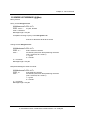
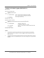
NMEA Protocol Support
The M12M Positioning Receiver firmware supports the NMEA 0183 format for GPS data output.
Output of data in the NMEA-0183 standard format allows a direct interface via the serial port to
electronic navigation instruments that support the specific output messages. NMEA formatted
messages may also be used with most commercially available mapping and tracking programs.
The following NMEA output messages are supported as per the NMEA-0183 Specification
Revision 2.0.1:
Message
GPGGA
GPGLL
GPGSA
GPGSV
GPRMC
GPVTG
GPZDA
Description
GPS Fix Data
Geographic Position Latitude/Longitude
GPS DOP and Active Satellites
GPS Satellites in View
Recommended Minimum Specific GPS/Transit Data
Track Made Good and Ground Speed
Time and Date
You can enable or disable each message output independently and control the update rate at
which the information is output. The seven NMEA messages may be individually programmed to
be sent out continuously at any rate from once-per-second to once-every-9999 seconds, or may
be requested as individually polled responses.
If back-up power is applied or if the receiver has the battery option, the M12M receiver retains the
output settings when powered off and reconfigures itself to the same state when powered up
again. If no back-up power is provided, the receiver will start up in the default state (Binary format
at 9600 baud with all messages in the polled configuration) each time it is powered on.
NMEA Commands to the Receiver
All NMEA commands are formatted in sentences that begin with the ASCII '$' character and end
with ASCII <CR><LF>. A five character sequence (PMOTG) occurs after the ASCII $, identifying
the command as a Proprietary MOTorola GPS command. A five character address occurs after
the $PMOTG. The first two characters are the talker ID (which is GP for GPS equipment), and the
last three characters are the sentence formatter (or message ID) from the list above. The next
four characters designate the update rate being requested. The command is then terminated with
an optional checksum and the normal Carriage Return/Line Feed characters. Several examples
are shown below. Note that unlike Binary messages, NMEA messages are not fixed length. Field
widths within the message can vary depending on the contained data, and are delimited by the
ASCII comma character.
As noted above, checksums are supported in NMEA protocol, but are not required as they are in
36
i-Lotus GPS Products - M12M User's Guide Revision 1.0 01May06
Chapter 2 - Receiver Descriptions
the binary protocol. The checksum is calculated by XORing the 8 data bits of each character in
the sentence between, but not including, the $ and the optional (*) or checksum (CS). The high
and low nibbles of the checksum byte are sent as ASCII characters.
NMEA Command Examples
1. Assume the user desires a single (polled) RMC message. The required
command string (without the optional checksum) is:
$PMOTG,RMC,0000,<CR><LF>
2. Assuming that the user now desires the RMC message to be sent once each second, the
command string would change to:
$PMOTG,RMC,0001,<CR><LF>
NMEA Response Examples
The response to the command in Example 1 above would be:
$GPRMC,hhmmss.ss,a,ddmm.mmmm,n,ddmm.mmmm,w,z.z,y.y,d.d,v*CC<CR><LF>
where:
•
•
•
•
•
•
•
•
•
•
•
•
•
‘$GPRMC’ is the message header
‘hhmmss.ss’ is the UTC time of the position fix in hours, minutes, and seconds
‘a’ is the current position fix status with ‘A’ designating a valid position, and ‘V’ indicating
an invalid position
‘ddmm.mmmm’ is the current latitude in degrees and minutes
‘n’ is the direction of the latitude with ‘N’ indicating North and ‘S’ indicating South
‘dddmm.mmmm’ is the current longitude in degrees and minutes
‘w’ is the direction of the longitude with ‘W’ indicating West and ‘E’ indicating East
‘z.z is the current ground-speed in knots
‘y.y’ is the current direction, referenced to true North
‘ddmmyy’ is the UTC date of the position fix
‘d.d’ is the magnetic variation in degrees
(always 0.0 with M12M)
‘v’ is the direction of the variation
(always nulled with M12M)
‘CC’ is the checksum
Note that unlike the binary messages, NMEA messages can vary in length. If any value has not
been determined yet the data position will be nulled. For example, if you request the RMC
message before the receiver has tracked any satellites and developed a position solution, the
response will look like this:
$GPRMC,,V,,,,,,,,,,*CC<CR><LF>
For the case where more than one output message is scheduled during the same one second
37
i-Lotus GPS Products - M12M User's Guide Revision 1.0 01May06
Chapter 2 - Receiver Descriptions
interval, the receiver will output all scheduled messages but will attempt to limit the number of
bytes transmitted each second to 400 bytes. For the case of multiple output messages, if the
next message to be sent fits into the 400 byte length goal, then the message will be output. For
example, if messages totaling 334 bytes are scheduled to be sent, and the user requests another
80 byte message, then 414 bytes will actually be sent. If the user requests yet another 70 byte
message, then its output will not be generated. The order for priority of transmitting messages is
simply alphabetical.
The NMEA messages are input and output on the primary serial port just as in binary mode. For
further details on the command formats see Chapter 5 of this document.
RTCM Differential GPS Support
The M12M positioning receiver supports the RTCM SC-104 format for the reception of differential
corrections. The receiver employs a decoding algorithm that allows the unit to directly decode the
RTCM Type 1 and Type 9 messages input on the second serial port (pin 5) at 2400, 4800, or
9600 baud. Having a separate port allows the M12M to simultaneously accept the RTCM format
data stream on the second port and process normal receiver input/output on the main port.
38
i-Lotus GPS Products - M12M User's Guide Revision 1.0 01May06
Chapter 2 - Receiver Descriptions
Input/Output Processing Time
User commands sent to the M12M are placed in an input buffer that is serviced once per second.
When powered on and available satellites are tracked, the current receiver position is available. If
insufficient satellite signals are received to develop a current fix, the last known position is output.
The message response time will be the time from the transmission of the first byte of input data to
the transmission of the last byte of output data. The command processing time will be skewed
since the time will be dependent on when the input message buffer is processed. For best case
processing, the input command would have to arrive just before the input buffer data is
processed, and the output response would have to be the first (or only) receiver output. For worst
case processing, the input command would have to arrive just after the input buffer data had
been processed, and the output response would have to be the last receiver output.
Assuming 1 ms per transmission of a data byte, assuming 50 ms command processing, and
assuming a uniform distribution for time of input command data entry, the best case, typical case,
and worst case scenarios are shown below.
Best Case UTC Time Correction command (@@Aw):
BC time = shortest command input + command processing + shortest command output
=
=
10 ms +50 ms +10 ms
70 ms
Typical Case UTC Time Correction command:
TC time = input anywhere across one second period + command processing + output anywhere
across one second period following command processing
=
=
0.5s+0.05s+0.475s
1.025 s
Worst Case UTC Time Correction command:
WC time = input beginning of one second period + output end of one second period
=
=
1 s+1 s
2s
Note: The one command where these times are not applicable is the receiver's Self Test
command (@@Ia). The Self-Test command takes 5-10 seconds to complete.
39
i-Lotus GPS Products - M12M User's Guide Revision 1.0 01May06
Chapter 2 - Receiver Descriptions
DATA LATENCY
The receiver can output position, velocity, and time data on the serial port at a maximum rate of
once each second. The start of the output data is timed to closely correspond with the receiver
measurement epoch. The measurement epoch is the point in time at which the receiver makes
satellite range measurements for the purpose of computing position. The first byte of serial data
in the position message is output between 0 and 50ms after the most recent receiver
measurement epoch. Refer to Figure 3.7 for the discussions that follow.
Let Tk be the most recent measurement epoch. The receiver takes about one second to compute
data from the satellite range measurements. Consequently, the data that is output 0 to 50 ms
after Tk represents the best estimate of the position, velocity, and time based on the
measurements taken one second in the past, at time Tk -1. Position data (latitude, longitude, and
height) is computed from the most recent measurement epoch data, and is output immediately
after the next measurement epoch, which is 1.0 to 1.05 seconds after the original measurements
were taken.
Figure 3.7: Position/Status/Data Output Message Latency
40
i-Lotus GPS Products - M12M User's Guide Revision 1.0 01May06
Chapter 2 - Receiver Descriptions
To compensate for the one second computational pipeline delay, a one second
propagated position is computed that corresponds to Tk based on the position and velocity data
computed from measurements taken at time Tk -1. In this way, the position data output on epoch
Tk will most closely correspond with the receiver true position when the data is output on the
serial port. Of course, there can be a position error due to the propagation process if the receiver
is undergoing acceleration. The error can be as large as 4.5 m for every G of acceleration. There
is no significant error under stationary or constant velocity conditions.
Position Data Latency
The position data output in the current data packet (i.e., at time Tk) is the result of a Least
Squares Estimation (LSE) algorithm using satellite pseudorange measurements taken at time Tk1. The resulting LSE position corresponding to time Tk-1 is then propagated one second forward by
the velocity vector (the result of an LSE fit using satellite pseudorange rate measurements taken
at Tk-1). The resulting propagated position is output at the Tk epoch.
Velocity Data Latency
The velocity data output in the current data packet (i.e., at time Tk) is the result of an LSE fit using
satellite pseudorange rate measurements taken at time Tk-1. The pseudorange rate
measurements are derived from the difference in integrated carrier frequency data sampled at
measurement epochs Tk-1 and (Tk-1 -200 ms). In effect, the resulting velocity data represents the
average velocity of the receiver halfway between Tk-1 and (Tk-1 -200 ms).
Time Data Latency
The time data output in the current data packet (i.e., at time Tk) is the result of an LSE fit using
satellite pseudorange measurements taken at time Tk-1. The time estimate at Tk-1 is then
propagated by one second plus the computed receiver clock bias rate at time Tk-1, before being
output at time Tk. The resulting time data is the best estimate of local time corresponding to the Tk
measurement epoch based on data available at Tk-1.
ONE PULSE PER SECOND (1PPS) TIMING
Measurement Epoch Timing
The M12M receiver timing is established relative to an internal, asynchronous, 1 kHz clock
derived from the local oscillator. The receiver counts the 1 kHz clock cycles, and uses each
successive 1000 clock cycles to define the time when the measurement epoch is to take place.
The measurement epoch is the point at which the receiver captures the pseudorange and
pseudorange rate measurements for computing position, velocity, and time.
When the receiver starts, it defines the first clock cycle as the measurement epoch. Every 1000
clock cycles from that point define the next measurement epoch. Each measurement epoch is
41
i-Lotus GPS Products - M12M User's Guide Revision 1.0 01May06
Chapter 2 - Receiver Descriptions
about one second later than the previous measurement epoch, where any difference from
1.000000000 seconds is the result of the receiver local oscillator intentional offset (about +60
µs/s) and the oscillator's inherent instability (+/-30 ppm over specified temperature range).
When the M12M processor computes receiver local time, this time corresponds to the time of the
last receiver measurement epoch. The Oncore process precisely determines this time to an
accuracy of approximately 20 to 300 ns depending on satellite geometry and the effects of
Selective Availability (if Selective Availability were to ever be reactivated by the DoD.)
The computed time is relative to UTC or GPS time depending on the time type as specified by the
user using the Time Mode command (@@Aw). The Oncore system timing is designed to slip
time when necessary in discrete one millisecond intervals so that the receiver local time
corresponds closely to the measurement epoch offset. The Oncore observes the error between
actual receiver local time and the desired measurement epoch offset and then slips the
appropriate integer milliseconds to place the measurement epoch to the correct integer
millisecond. When a time skew occurs (such as after initial acquisition or to keep time within limits
due to local oscillator drift), the receiver lengthens or shortens the next processing period in
discrete one millisecond steps.
The rising edge of the 1PPS signal is the time reference. The falling edge will occur
approximately 200 ms (+/-1 ms) after the rising edge. The falling edge should not be used for
accurate time keeping.
Output Data Timing Relative To Measurement Epoch
Figure 3.8: Output Signal Timing
The 12 Channel Position/Status/Data Messages (@@Ha and @@Hb), the T-RAIM Setup and
Status Message (@@Hn), and the Time Message (@@Gb) are the only output messages
containing time information. If enabled, these messages will be output from the receiver shortly
after a measurement epoch. Generally, the first data byte in the first message will be output
42
i-Lotus GPS Products - M12M User's Guide Revision 1.0 01May06
Chapter 2 - Receiver Descriptions
between 0 to 50 ms after a measurement epoch. For the Position/Status/Data Message, the
time output in the message reflects the best estimate of the most recent measurement epoch. A
simple timing diagram is shown in figure 3.8.
1PPS Cable Delay Correction and 1PPS Offset (M12M Timing Receiver Only)
Users can compensate for antenna cable length with the 1PPS Cable Delay Command (@@Az).
The 1PPS can also be positioned anywhere in the one second window using the 1PPS Offset
command (@@Ay). The rising edge of the 1PPS is placed so that it corresponds to the time
indicated by the following equation:
1PPS rising edge time = top of second -1PPS cable delay + 1PPS offset
Consider the following example:
True Top of second =
10.000000000 s
1PPS cable delay correction = 0.000654321 s
1PPS offset =
0.100000000 s
1PPS rising edge time =
10.099345679 s
The rising edge of the 1PPS signal is adjusted so that it occurs corresponding to the fractional
part of time equal to the total above. The fractional part of time is measured relative to UTC or
GPS time depending on the setting of the Time Mode.
OPERATIONAL CONSIDERATIONS
When powered on, the M12M Oncore Receiver automatically acquires and tracks satellites;
measures the pseudorange and phase data from each of up to twelve satellites; decodes and
collects satellite broadcast data; computes the receiver's position, velocity, and time; and outputs
the results according to the current I/O configuration selected by the user.
43
i-Lotus GPS Products - M12M User's Guide Revision 1.0 01May06
Chapter 2 - Receiver Descriptions
Time to First Fix (TTFF)
TTFF is a function of position uncertainty, time uncertainty, almanac age, and ephemeris age as
shown in the table below. The information shown below in Table 3.8 assumes that the antenna
has full view of the sky when turned on.
Table 3.8: Typical M12M TTFF Information
Power-up
State
Hot
Warm
Cold
(default)
Initial Error
POS
100
km
100
km
N/A
Age
TTFF
M12M
Timing
TIME
ALMANAC
EPHEMERIS
TTFF
M12M
3 min
1 month
< 4 hrs
< 15s
< 15s
3 min
1 month
Unavailable
< 40s
< 40s
N/A
Unavailable
Unavailable
< 60s
< 150s
N/A - Not applicable. Knowledge of this parameter has no effect on TTFF in this configuration.
First Time On
When the M12M receiver powers up for the first time after factory shipment, the initial date and
time will be incorrect. This will force the receiver into a cold power-up state (cold start), and it will
begin to search the sky for all available satellites. After one satellite has been acquired, the date
and time will automatically be set using data downloaded from the satellite. When three or more
satellites are tracked, automatic position computation is initiated. At power down, the M12M
receiver does not remember its current configuration unless the receiver is fitted with an onboard
lithium cell or external back-up power is applied.
Initialization
When powered up, the M12M acquisition and tracking algorithms will automatically start acquiring
satellites and will compute position when it acquires at least three. For each of the user controlled
outputs, the receiver (if battery backed) remembers the previously requested message formats
(continuous or polled) and the update rate. If no messages were active the last time the receiver
was used, it waits for an input command before it outputs any other data, even though it may
have acquired satellites and is computing position fixes internally.
The M12M does not need to be initialized to its approximate position to acquire satellites and
compute position, nor does it require a current satellite almanac. However, the TTFF will be
considerably shorter if you help the receiver locate satellites by providing it with the current date
and approximate time, approximate local position and a current satellite almanac. This will allow
the receiver to perform a "Warm Start" vs. a "Cold Start".
44
i-Lotus GPS Products - M12M User's Guide Revision 1.0 01May06
Chapter 2 - Receiver Descriptions
If backup power is available, the M12M retrieves its last known position coordinates from RAM
when main power is reapplied, and uses this information in the satellite acquisition algorithm. In
addition, the receiver retains the almanac and last used satellite ephemeris as long as the backup
power is applied. If you move the receiver a great distance before using it again, it will find and
acquire satellites, but the TTFF may be longer than normal because the receiver will start looking
for the satellites that are actually visible at the last known coordinates. You can initialize the new
approximate position coordinates for faster TTFF if desired.
Each message in the I/O format description in Chapter 5 shows the default value for each
parameter.
Shut Down
It is recommended that the receiver not be shut down within 35s of computing an initial 2D or 3D
position fix. This allows time for a full set of ephemeredes to be downloaded to RAM, which may
shorten the next startup time.
45
i-Lotus GPS Products - M12M User's Guide Revision 1.0 01May06
Chapter 2 - Receiver Descriptions
Received Carrier to Noise Density Ratio (C/No)
The Position/Status/Data Message output C/No for each receiver channel, which can be used to
determine the relative signal levels of received satellite signals (refer to Figure 3.9 below). C/No is
the received carrier to noise density ratio. The units are dB-Hz, where No is the noise density
ratio received in a 1 Hz bandwidth. The C/No may be converted into received signal strength
using the plot in Figure 3.9.The satellite signal strength is measured at the antenna input. Typical
"good" C/No numbers reported by an with a properly installed antenna system are between 40
and 55 dB-Hz.
Figure 3.9: Approximate Signal Strength vs. Reported C/No
46
i-Lotus GPS Products - M12M User's Guide Revision 1.0 01May06
Chapter 2 - Receiver Descriptions
SETTING UP RECEIVERS FOR SPECIFIC APPLICATIONS
M12M as a Standard Autonomous Positioning Receiver
As supplied, the M12M positioning receiver will work quite well without any operator intervention
except for enabling the desired output messages and a couple of setup steps. These are:
•
•
•
Enabling the desired message strings (typically @@Ha or @@Hb, @@Bb, etc.)
Setting the antenna Mask Angle using the @@Ag command. In the default condition the
M12M positioning receiver's mask angle is set at 0o, but position accuracy will be
improved by setting this angle somewhere in the range of 5-10o. This is due to the fact
that the ionospheric correction algorithms used by the receiver are less accurate for lowlying satellites.
If NMEA operation is desired, this mode should be invoked using the @@Ci command.
Once in NMEA mode, any of the seven NMEA sentences may be enabled with the
appropriate commands as detailed earlier.
NOTE: Once in NMEA mode, you will be unable to
modify receiver operating parameters such as Mask
Angle, Satellite Ignore List, etc., nor will you be able
to access any of the receiver diagnostics such as
the Self-Test or the status bits in the @@Ha and
@@Hb messages. If you wish to use any of these
functions you must temporarily switch back to
binary mode, perform the desired operations, and
then switch back to NMEA protocol.
M12M as a Positioning Receiver Using Differential Corrections
Setting up the M12M for use as a differential 'rover' is identical to the setup shown above except
for a couple of minor additions:
•
•
Disable the ionospheric and tropospheric corrections by invoking mode 0 in the @@Aq
Ionospheric Corrections Select Command. Having the corrections disabled in both the
rover and base station will cancel out the ionospheric delay, whereas the ionospheric
correction algorithm is not as accurate.
Apply corrections to the receiver either through Port 1 or 2, depending upon the
correction format. Legal options are as follows:
1.
2.
M12M rover receiver operating in binary mode - Apply binary corrections from
either a VP Oncore or M12M Oncore Base Station to the main serial port (Pin 2)
using the @@Ce message, or apply RTCM-104 Type 1 or 9 corrections (from a
Coast Guard beacon or other source) to the second serial port on Pin 8.
Corrections may be applied at 2400, 4800, or 9600 baud.
M12M rover receiver operating in NMEA mode - Corrections MUST be in RTCM104 format and applied to the second serial port as detailed above.
47
i-Lotus GPS Products - M12M User's Guide Revision 1.0 01May06
Chapter 2 - Receiver Descriptions
Note that a receiver operating in differential mode will discard corrections once they have aged
more than 90 seconds. This is normally not a problem as corrections are typically applied every
5-20 seconds, but if you have a poor RF link between the Base Station and the rover, this
condition may occur. The receiver will automatically switch between differential and autonomous
modes as corrections are received or time out.
M12M as a Differential Base Station
In order to generate the most accurate corrections, the M12M being used as a Base Station must
be put in Position-Hold mode with the antenna at an accurately surveyed position. The positioning
accuracy of all of the rover receivers is limited by the accuracy of this position. To set up a Base
Station, the following steps should be followed:
•
•
•
•
•
•
Disable the ionospheric and tropospheric corrections by invoking mode 0 in the @@Aq
Ionospheric Corrections Select Command.
Set the satellite mask angle to 10 degrees using the @@Ag command.
Enter the Position-Hold-Position using the @@As command. The coordinates can either
be determined by a professional site-survey, or you may use the Base Station receiver
along with a software program such as WinOncore12 to develop a reasonably accurate
position by allowing the receiver to run for 12 - 24 hours and utilize the Mean position
calculated by the software.
Place the receiver in Position-Hold mode by invoking mode 1 of the @@Gd Position
Control Message.
Enable the output of differential corrections from the base station using the @@Bh
command. Allowable update rates are once per second to once per 255 seconds. As a
practical matter, corrections are usually sent out every 3-20 seconds. Any longer than a
20 second update rate may tend to cause larger errors in reported position. Once the
@@Bh command is invoked, the base station will start issuing @@Ce correction
messages at the requested rate. Two @@Ce messages will be issued back-to-back if
more than 6 satellite corrections are available as the @@Ce message format only
handles a maximum of 6.
If the rover is receiving the corrections, it will respond to the @@Ce messages with an
@@Ck acknowledgement message.
M12M as a Precision Timing Receiver
As received, the M12M Timing Receiver default operating parameters are already set up for
optimal operation. There is no need to set the Mask Angle to 10 degrees as this is the default
condition for this receiver.
•
•
Enter the Position-Hold-Position using the @@As command. The coordinates can either
be determined by a professional site survey or you can use the Auto-Survey function of
the M12M timing receiver. Invoking this function (mode 3 of the @@Gd command) will
automatically average 10,000 position fixes and then force the receiver into PositionHold.
Set the timing parameters using the @@Gf, @@Ge, and @@Hn messages
@@Gf – This message is used to set the T-RAIM alarm limit. The receiver defaults time
is 1000ns, but the user may select any value between 300 and 1,000,000ns using this
command. Typical values are between 500 and 1000ns.
48
i-Lotus GPS Products - M12M User's Guide Revision 1.0 01May06
Chapter 2 - Receiver Descriptions
@@Ge – This message is used to turn the T-RAIM function on and off. The receiver must be in
Position-Hold mode in order to get full functionality from the T-RAIM algorithm. If the receiver is
left in positioning mode the T-RAIM can only detect a bad satellite, it cannot remove it from the
time solution.
@@Hn – The @@Hn T-RAIM Status Message is normally set up to send status strings once a
second so that the user’s external software can be immediately alerted to any alarm conditions.
49
i-Lotus GPS Products - M12M User's Guide Revision 1.0 01May06
Chapter 2 - Receiver Descriptions
This page intentionally left blank
50
i-Lotus GPS Products - M12M User's Guide Revision 1.0 01May06
Chapter 4 - Antenna Descriptions
Chapter 4 – Antenna Descriptions
CHAPTER SUMMARY
Refer to this chapter for the following:
•
Product descriptions for the antenna for M12M navigation and M12M Timing
•
Installation precautions and setup
•
Electrical Parameters
•
Mechanical Dimensions
51
i-Lotus GPS Products - M12M User's Guide Revision 1.0 01May06
Chapter 4 - Antenna Descriptions
M12M Antenna Type I
Antenna Description
The antenna is designed to operate with the successful family of Oncore GPS receivers, as well
as many GPS receivers from other manufacturers. The 3V version of the GPS Antenna is
specifically designed to operate with M12M Oncore receivers. The antenna is a general purpose
GPS active antenna designed to meet the stringent environmental and performance needs of the
automotive market place.
The antenna design reflects high standard for performance when operating in foliage/urban
canyon environments and in the presence of electromagnetic interference. The small footprint,
low profile package and the shielded LNA (low noise amplifier) offer significantly enhanced
performance while operating in a variety of GPS environments. Furthermore, magnetic and blind
hole direct mounting options make the antenna suitable for a number of different installation
configurations.
52
i-Lotus GPS Products - M12M User's Guide Revision 1.0 01May06
Chapter 4 - Antenna Descriptions
Table 4.1 Active Antenna Technical Characteristics
GENERAL
CHARACTERISTICS
PERFORMANCE
CHARACTERISTICS
Antenna Description
Passive dielectric patch antenna
Top and bottom radome plastic housing
assembly
Active low noise amplifier/filter –PWB
assembly RF cable with
connector assembly
Operating Frequency
Input Impedance
VSWR
Bandwidth
Polarization
Azimuth Coverage
Elevation Coverage
Gain Characteristics of
Antenna Element
Filtering
L1 (1575.42 MHz, +/- 1.02 MHz)
50 Ohm
1.5 (typical) @ 1575.42 MHz (2.5 max)
10 to 45 MHz ( ± 3dB points)
Right hand circular
360°
0° to 90°
+2.0 dBic minimum at zenith
-10 dBic minimum at 0° elevation
-30dB @ 1675 MHz (typical)
-30dB @ 1475 MHz (typical)
3 Vdc version
24dB (typical, including 5 dB cable loss)
<1.8dB (typical), 2.2dB (max)
Vibration: 7.7 G’s (Military Standard 810E)
Shock: 100 G’s (Military Standard 810E)
3 V ± 0.2 Vdc for GC3LPxxxxx models
16mA (typical), 20mA (max)
38 x 34 x 13.2 mm ± 0.5 mm
Antenna Gain
Noise Figure
Dynamics
ELECTRICAL
CHARACTERISTICS
PHYSICAL
CHARACTERISTICS
Power Requirements
Current Consumption
Dimensions
Weight
Mounting Methods
Radome color
Cable Connectors
ENVIRONMENTAL
CHARACTERISTICS
MISCELLANEOUS
NOTE
< 89 grams (including 5m cable and
connector)
Magnetic and Blind holes (2) Taplite screw
size of 2.6 x 5 mm (1 mm thick base plate)
Black
MMCX r/a plug – Standard for 3 Vdc antenna
Antenna to receiver
Interconnection
Single shield RG-316 type coaxial cable
5 meters (25 ft.) long (See connectors above)
Operating
Temperature
Storage Temperature
Thermal Testing
UV Radiation
Salt Spray Test
Immersion Test
Optional Features
-40ºC to +100ºC
-40ºC to +100ºC
Cycled 600 hours at –40°C and +100°C
Sunshine Carbon Arc System – JIS D0205
320 hours, Spray 5% NaCl solvent at +35°C
60 minutes at 1 meter
Special order model: Substrate (w/o radome
and base) version with cable and connector
All values above are referenced to 25°C unless indicated otherwise
53
i-Lotus GPS Products - M12M User's Guide Revision 1.0 01May06
Chapter 4 - Antenna Descriptions
Antenna Gain Pattern
The sensitivity of an antenna as a function of elevation angle is represented by the gain pattern.
Some directions are much more appropriate for signal reception than others, so the gain
characteristics of an antenna play a significant role in the antenna's overall performance. A crosssectional view of the antenna gain pattern along a fixed azimuth (in a vertical cut) is displayed in
the following figure. The gain pattern clearly indicates that the antenna is designed for full, upper
hemispherical coverage, with the gain diminishing at low elevations. This cross-section is
representative of any vertical cross section over a full 360 degree azimuth range and thus, the 3
dimensional gain pattern is a symmetric spheroidal surface. It is important to note that this gain
pattern varies in elevation angle, but not in horizontal azimuth. This design is well-suited for many
GPS applications, accommodating full sky coverage above the local horizon and
minimizing ground reflected multipath effects.
Figure 4.2: Typical Antenna Gain Pattern
54
i-Lotus GPS Products - M12M User's Guide Revision 1.0 01May06
Chapter 4 - Antenna Descriptions
Mechanical Dimensions
All dimensions are in mm and are for reference purposes only.
Figure 4.3: Magnet/Direct Mount Configuration
55
i-Lotus GPS Products - M12M User's Guide Revision 1.0 01May06
Chapter 4 - Antenna Descriptions
Mechanical Dimensions (Continued)
All dimensions are in mm and are for reference purposes only.
Figure 4.4: Antenna Substrate Configuration
56
i-Lotus GPS Products - M12M User's Guide Revision 1.0 01May06
Chapter 4 - Antenna Descriptions
RF Connectors/Cables Information
Shikoku 1.5DS-QEHV coaxial cable is used in the antenna assemblies. This cable is very similar
to RG-316. Figure 4.5 shows simplified views of the cable construction while Table 4.8 details the
electrical and mechanical characteristics.
Figure 4.5: Antenna Cable Construction
Table 4.4 Characteristics of coaxial cable
Item
Center Conductor
Maximum inner conductor
resistance (20°C)
Dielectric/Insulation
Outer Conductor
Jacket Sheath
Approximate weight of cable
Minimum bend radius
Test voltage
Minimum insulation resistance
Characteristic Impedance
Operating Temperature
Range
Standard Attenuation
Specification
Tinned Annealed Copper Wire, 0.54mm
diameter (7strands of 0.18 mm)
120 ohms/km
Cross linked polyethylene, thickness 0.53mm
Tinned annealed copper
wire braid, outside diameter - 1.6mm
Material Thickness 0.5mm. Finished Diameter
of 3.1 +/- 0.20mm
15 kg/km
31mm
1000V/min
1000 Meg-ohm/km
50 +/- 2 ohms
-40 to +105 ºC
0.91 dB/m at 900 MHz
1.26 dB/m at 1500 MHz
1.32 dB/m at 1600 MHz
1.50 dB/m at 1900 MHz
1.54 dB/m at 2000 MHz
57
i-Lotus GPS Products - M12M User's Guide Revision 1.0 01May06
Chapter 4 - Antenna Descriptions
Antenna Placement
When mounting the antenna module, it is important to remember that GPS positioning
performance will be optimal when the antenna patch plane is level with the local geographic
horizon, and the antenna has full view of the sky ensuring direct line-of-sight to all visible
satellites over head.
Figure 4.6: Proper Antenna Placement
58
i-Lotus GPS Products - M12M User's Guide Revision 1.0 01May06
Chapter 4 - Antenna Descriptions
Antenna System RF Parameter Considerations
Both the gain and the noise of the overall system affect the performance of the A/D converter in
the Oncore GPS receiver. The illustration below illustrates typical values for the M12M receiver
when used with the antenna and the standard length of 5 meters of cable. The thresholds and
ranges listed should be considered to have a tolerance of 2 to 3 dB. Figure 4.7 below details a
typical configuration.
System Constraints:
•
The gain in decibels is cumulative through all stages (i.e. G = G1+ G2 + G3 .. ). The
optimal gain of the antenna, cabling and any in-line amplifiers and splitters for the
receiver is between 18 and 36 dB. The may operate outside of the optimal gain range
but performance will degrade. Therefore, we do not recommend operating outside of the
optimal gain range as indicated above. For the system illustrated below, the external gain
is approximately 24 dB in front of the receiver.
•
System noise (F) is not to exceed 4dB. The cascaded system noise figure
formula is:
f 2−1 f 3−1
f = f 1 + g 1 + g 1× g 2 ........., (=1.9dB for the system shown below)
.
where ƒ1 is the noise figure for stage one and g1 is the gain for stage one. Note that all of the
values used in this equation are absolute. The resulting number must be converted back to
decibels in order ascertain if it is less than 4dB and to compare it with other antenna systems
configurations.
Recall the formula for converting absolute values to decibels, and decibels to absolute values:
10logƒ = ƒ(dB).
Stage 1
antenna with low noise amplifier (LNA)
g = 29dB, ƒ = 1.8dB
Stage 3
M12M Oncore receiver
G =85dB, ƒ = 5.5dB
Stage 2
5m of RG-174 Cable
g = -5dB, ƒ = -5dB
Figure 4.7: Typical System Gain/Noise Figure Calculations
59
i-Lotus GPS Products - M12M User's Guide Revision 1.0 01May06
Chapter 4 - Antenna Descriptions
60
i-Lotus GPS Products - M12M User's Guide Revision 1.0 01May06
Chapter 4 - Antenna Descriptions
M12M Antenna Type II
Antenna Description
The antenna is intended for use in GPS timing applications and is designed for use with Oncore
receivers as well as many GPS receivers from other manufacturers. GPS signals are received by
the antenna, amplified within the antenna assembly, and then relayed via cable to the receiver
module for processing. The conical radome housing is manufactured from an Ultra Violet (UV)
resistant material. A tubular mounting nut specially designed for ease of weatherproofing, assures
superior performance while operating in the world’s most challenging weather environments.
61
i-Lotus GPS Products - M12M User's Guide Revision 1.0 01May06
Chapter 4 - Antenna Descriptions
Table 4.7 Antenna Technical Characteristics
GENERAL
CHARACTERISTICS
Antenna Description
PERFORMANCE
CHARACTERISTICS
Input Impedance
VSWR
Bandwidth
Filtering
Polarization
Azimuth Coverage
Elevation Coverage
Patch Element Gain
Characteristics
LNA Gain
Noise Figure
Dynamics
Input Voltage Range
Current Requirements
Dimensions
Weight
Mount
Connector
Operating Temperature
Storage Temperature
Humidity
UV Radiation Test
ELECTRICAL
CHARACTERISTICS
PHYSICAL
CHARACTERISTICS
ENVIRONMENTAL
CHARACTERISTICS
MISCELLANEOUS
NOTE
Molded UV- resistant plastic conical
radome
Aluminum die cast bottom housing
Electrically shielded low noise amplifier
assembly
Operating Frequency L1 (1575.42 MHz,
+/- 2 MHz)
50 Ohms
1.5 (typical) @ 1575.42 MHz
25 MHz (typical) +/- 3dB points)
40dB at +/- 50MHz from L1
Right hand circular
360°
0° to 90°
+2.0 dBic minimum at zenith, -10 dBic
minimum at 0° elevation
25dB (typical)
< 1.5dB (typical)
Vibration: SAE J1455
5 +/- 0.25 Vdc
26 mA @ 5 Vdc (typical)
102.0 diameter x 82.0 height (mm)
312 grams
Center mount (M28 nut)
N jack
-40ºC to +85ºC
-40ºC to +85ºC
85% non-condensing @ +30ºC to +60ºC
JIS D0202 (Sunshine Carbon Arc
System)
Salt Spray Test
Spray 5% NaCl solvent at +35°C
Immersion Test
1 meter (with connector sealed)
Transient Voltage Test
+/- 12 kV
Optional Features
Post Mount Bracket, P/N (MNT62312B1)
All performance measurements are typical and referenced to 25°C
unless indicated otherwise
62
i-Lotus GPS Products - M12M User's Guide Revision 1.0 01May06
Chapter 4 - Antenna Descriptions
Antenna Gain Pattern
The sensitivity of an antenna as a function of elevation angle is represented by the gain pattern.
Some directions are much more appropriate for signal reception than others, so the gain
characteristics of an antenna play a significant role in the antenna's overall performance.
A cross-sectional view of the antenna gain pattern for the antenna along a fixed azimuth (in a
vertical cut) is displayed in the following figure. The gain pattern clearly indicates that the antenna
is designed for full, upper hemispherical coverage, with the gain diminishing at low elevations.
This cross-section is representative of any vertical cross section over a 0 to 360 degree azimuth
range and thus, the 3 dimensional gain pattern is a symmetric spheroidal surface. It is important
to note that this gain pattern varies in elevation angle, but not in horizontal azimuth. This design is
well suited for many GPS applications, accommodating full sky coverage above the local horizon
and minimizing ground reflected multipath effects.
Figure 4.9: Typical Antenna Gain Pattern
63
i-Lotus GPS Products - M12M User's Guide Revision 1.0 01May06
Chapter 4 - Antenna Descriptions
Installation Precautions
The following precautions should be taken into consideration to avoid the introduction of hazards
and adversely affecting performance when installing the GPS Antenna.
•
Mounting bracket must be grounded in accordance with the National
Electric Code Section 810-21.
•
Avoid contact with power lines; serious injury could result.
•
Avoid making the antenna the highest point on the roof.
•
Locate the antenna such that there is a 360° view of the sky.
•
Do NOT place any obstructions over or around the antenna.
•
For optimal performance, do NOT place the antenna inside a building.
•
To prevent ESD damage to the antenna, do NOT touch the center pin on the
antenna connector.
•
Use only a 50 ohm transmission line when connecting to the antenna.
•
Do NOT apply more than 5 VDC to the center pin of the antenna.
•
If more than one receiver is fed by a single antenna, ensure that the receivers are
isolated by a high isolation RF splitter. Low isolation passive splitters can cause suboptimal performance.
Antenna Mounting
The antenna is installed with a center-mounting scheme. It uses an industry
standard ‘N’ connector that is incorporated with the post mount bracket. The minimum torque to
assemble the antenna and custom hex nut on the post mount bracket is 70 kg-cm (61 in-lb); do
not exceed 100 kg-cm (86.8 inch-lb). It is recommended that an adjustable wrench with a
minimum opening of 1½ inches be used for this assembly. For optimal performance, ensure that
the base of the antenna is positioned as close as possible to the top of the mounting pole. Select
a mounting location with a clear view of the sky (360°) and use extreme caution when mounting
near high voltage power lines.
It is recommended that the mounting bracket, designed specifically for the antenna, be used
when installing the antenna. It can be used to install the antenna to a nominal 1 inch schedule 40
size pipe (approximately 1.6” OD). The four units included in the mounting assembly are the Ubolt, post mount bracket, lock washer and hex nut as illustrated in the following figure.
Antenna in Extreme Weather and Environmental Conditions
To provide additional protection against extreme weather and environmental conditions, a length
of plastic tubing covering the N connector on the bottom of the antenna is recommended to keep
driven rain from directly impinging on the connector mating area. This tubing should be secured
64
i-Lotus GPS Products - M12M User's Guide Revision 1.0 01May06
Chapter 4 - Antenna Descriptions
to the mounting nut of the antenna assembly and should extend several inches past the mating
N connectors. A product similar to Armstrong’s Armaflex Pipe Insulation Tubing products is
recommended. More information on this product can be found at www.armaflex.com. Use a
weather resistant cable tie or clamp to secure the tubing material to the mounting nut.
Antenna Cable and Connector Requirements
The antenna module consumes five-volt power diplexed from the interconnecting
coaxial cable. A 50 ohm coaxial cable is recommended for proper connection of the antenna
module to the receiver module. Note that for GPS receivers such as the , signal attenuation along
the cable should not exceed 8 dB at a frequency of 1575.42 MHz (the GPS L1 frequency). For
RG-58 cables, the maximum cable length is restricted to approximately 12m to satisfy this 8 dB
requirement.
For long cable runs, cables specifically designed for use at microwave frequencies are
recommended. These cables are typically constructed with a low-loss foam dielectric between the
center conductor and the outer shield.
The antenna uses an industry standard female N connector. Weatherproof mating N-connectors
are required to ensure a water resistant seal. Some suggested
cable connector vendors are:
•
AMP
•
Amphenol
•
Huber + Suhner
65
i-Lotus GPS Products - M12M User's Guide Revision 1.0 01May06
Chapter 4 - Antenna Descriptions
Environmental Tests
Provided below is an outline of the product durability and environmental specifications to which
the antenna was qualified.
Durability Validation Tests
Type of Test
Test Description
Thermal cycling Cycle Test:
Temperature Range
600 hours
-40 to +85 ºC
Thermal Shock Cycle Test:
Temperature range
200 hours
-40 to +85ºC
Humidity Cycle Test:
Cycling temperature
240 hours
-30 to +60ºC at 85% R.H.
High Temperature Storage Test:
+85ºC.
Low Temperature Storage Test:
-40 ºC.
Vibration Test:
Ref. spec: MIL STD 810E, Method 516.4, procedure IV
modified.
Drop Test:
Ref. spec: MIL STD 810E, Method 516.4, procedure IV
modified. 1 meter drop onto concrete surface.
Shipping Drop Test:
1 meter drop onto concrete surface, one corner, three
edges, all six faces.
ESD Test:
Tested from 5 KV to 15 kV
Immersion Test:
Module (not powered) stabilized at 45 ºC is immersed in
18 ºC water for 20 minutes (depth 1 meter.)
Salt Spray:
Spray 5% NaCl solvent (at 35 ºC)
Chemical Compatibility:
Liquid household laundry detergent: (diluted with water
50/50)
Liquid automobile wax
Automobile vinyl top cleaner
Kerosene
Isopropyl Alcohol
Ultraviolet Radiation
Sunshine carbon arc system (JIS D 0202)
Voltage Transient Test:
Max Voltage: ± 12 Kava. Max Capacitance: 1000pF
3 transient discharges applied in each polarity: to
antenna top radome, bottom housing, and RF connector
66
i-Lotus GPS Products - M12M User's Guide Revision 1.0 01May06
Chapter 4 - Antenna Descriptions
THIS PAGE INTENTIONALLY LEFT BLANK
67
i-Lotus GPS Products - M12M User's Guide Revision 1.0 01May06
Chapter 5 - I/O Commands
Chapter 5 - I/O COMMANDS
CHAPTER SUMMARY
Refer to this chapter for the following:
•
The I/O commands supported by the M12M Oncore receiver
•
Detailed command descriptions
68
i-Lotus GPS Products - M12M User's Guide Revision 1.0 01May06
Chapter 5 - I/O Commands
OVERVIEW
The Binary commands can be used to initialize, configure, control and monitor the M12M
receivers. The binary commands are supported on the primary communications port at 9600
baud. Immediately following this page are listings of the input commands in alphabetical order.
Command and response structures are detailed on subsequent pages.
The input and output data fields following the message headers contain binary data that can be
interpreted as scaled floating point or integer data. The field width and appropriate scale factors
for each parameter are described in the individual I/O message format descriptions. Polarity of
floating point data is described via two's complement presentation.
Input commands may also be of the type query current parameter status, or enable and disable
the output of data or status messages. These output status messages include those that the
external controller will use for obtaining position, velocity, time, and status data.
Some care must be exercised in interpreting the command arguments. On the following pages it
sometimes makes sense to display the command arguments as ASCII characters, while in others
the hex representation may be a little clearer. As mentioned previously, the receiver doesn’t really
care which method is used to generate the messages sent to the receiver so long as the binary
strings sent to the receiver meet the specifications. Where possible, complete hex command
strings have been included as examples of what the complete command strings look like. Once a
basic understanding of the message protocols is developed by the user, things will become much
clearer.
Also included in this chapter are message structures for the seven NMEA messages supported
by the M12M positioning receiver (The NMEA protocol is not supported by the M12M timing
receiver.
The WinOncore12 mnemonics shown in the following table are only to be used with the ‘Extra
Message’ window in WinOncore12. Each mnemonic causes WinOncore12 to run a macro that
sends a properly formatted string to the along with the checksum, carriage return, and line feed.
See the WinOncore12 help files for further explanation in the use of these commands.
69
i-Lotus GPS Products - M12M User's Guide Revision 1.0 01May06
Chapter 5 - I/O Commands
I/O COMMAND LIST INDEX BY BINARY COMMAND
Table 5.1: Input Commands Listed by Binary Command Header
Binary
Command
@@Ag
@@Am
@@AM
Satellite
Receiver
Position
@@AN
@@Ao
@@AO
Setup
Setup
Setup
@@Ap
@@AP
@@Aq
Setup
Timing
Setup
@@AQ
@@As
Position
Timing
@@AS
@@Aw
@@Ay
@@Az
@@Bb
Position
Time
Time
Time
Satellite
@@Bd
Almanac
@@Be
@@Bf
@@Bh
Almanac
Ephemeris
DGPS
@@Bj
@@Bo
Setup
Time
@@Bp
Receiver
@@Cb
Almanac
Function
Description
Satellite Mask Angle
Satellite Ignore List
Position Lock
Parameters
Marine Filter Select
Datum ID Codes
RTCM Port Baud Rate
Select
User Defined Datum
1PPS/100PPS Select
Ionospheric Correction
Select
Position Filter Select
Position-Hold
Parameters
Position Lock Select
UTC Correction Select
1PPS Offset
1PPS Cable Delay
Satellite Visibility
Message
Almanac Status
Message
Almanac Data Request
Ephemeris Data Input**
Pseudorange
Correction Request
Leap Second Status
UTC Offset Output
Message
Request
UTC/Ionospheric Data
Almanac Data Input
WinOncore
Mnemonic
mask
ignore
lockp
M12M
√
√
M12M
Timing
√
√
√
Page
#
73
75
77
filter
datum
p2baud
√
√
udatum
pps100hz
ion
√
√
√
85
87
√
√
89
pfilter
php
√
√
91
√
√
93
locke
utc
ppsoff
ppsdelay
vis
√
√
√
√
√
95
97
99
101
√
√
103
√
√
105
almout
ephin
corout
√
√
√
√
107
109
leapsec
utcoff
√
√
113
√
√
115
√
√
117
√
√
119
alm
utcion
almin
√
√
83
√
70
i-Lotus GPS Products - M12M User's Guide Revision 1.0 01May06
79
81
111
Chapter 5 - I/O Commands
Table 5.1: Input Commands Listed by Binary Command Header (continued)
Binary
Command
@@Cc
Function
Description
Ephemeris
Ephemeris Data Output
WinOncore
Mnemonic
-------
M12M
M12M
Timing
√
√
@@Ce
@@Cf
@@Ch
DGPS
Receiver
Almanac
Pseudorange Correction Input
Set to Defaults
Almanac Data Response
corin
default
-----
√
√
√
√
√
@@Ci
@@Cj
@@Ck
NMEA
Receiver
DGPS
Switch I/O to NMEA Protocol
Receiver ID
Pseudorange Correction Ack
ioformat
id
-----
√
√
√
@@Co
@@Eq
@@Ga
@@Gb
@@Gc
@@Gd
@@Ge
@@Gf
@@Gj
@@Gk
@@Ha
@@Hb
Receiver
Position
Position
Time
1PPS
Position
Time
Time
Time
Setup
Position
Position
@@Hn
Time
@@Hr
@@Ia
@@Sz
GPGGA
GPGLL
GPGSA
GPGSV
GPRMC
GPVTG
GPZDA
FOR
DGPS
Setup
Receiver
NMEA
NMEA
NMEA
NMEA
NMEA
NMEA
NMEA
NMEA
UTC/Ionospheric Data Input
ASCII Position Message
Combined Position Message
Combined Time Message
1PPS Control Message
Position Mode Control Message
T-RAIM Select Message
T-RAIM Alarm Message
Leap Second Pending
Vehicle Identification
12 Channel Position/Status/Data
12 Channel Short Position
Message
12 Channel T-RAIM Status
Message
Inverse DGPS Pseudorange
12 Channel Self-Test
System Power-On Failure
GPS Fix Data
Geographic Latitude/Longitude
GPS DOP and Active Satellites
GPS Satellites in View
Recommended Minimum Data
Track Made Good and Speed
Time and Date
Switch to Binary
----as8
compo
comtim
ppscon
holdcon
tr12en
trmalrm
leap12
vin
ps12
psd
√
√
√
√
√
√
√
√
√
√
√
√
√
√
√
√
√
√
√
√
see
@@Bf
121
123
see
@@Cb
125
127
see
@@Ce
129
133
137
139
143
145
147
149
151
153
155
√
√
161
√
165
√
traim12
----selftest12
-------------------------------------
√
√
√
√
√
√
√
√
√
√
√
167
173
175
177
181
183
185
187
189
191
193
√
√
71
i-Lotus GPS Products - M12M User's Guide Revision 1.0 01May06
Page #
Chapter 5 - I/O Commands
This page intentionally left blank
72
i-Lotus GPS Products - M12M User's Guide Revision 1.0 01May06
Chapter 5 - I/O Commands
SATELLITE MASK ANGLE COMMAND (@@Ag)
Applicability: M12M Positioning and Timing receivers
The receiver will attempt to track satellites for which the elevation angle is
greater than the satellite mask angle. This parameter allows the user to control the elevation
angle that was used for this decision. Typical values are between 5 and 10 degrees. Depending
on the antenna used, the receiver is capable of tracking satellites down to the horizon, but range
and therefore time errors will increase due to atmospheric distortion of the signals from the low
satellites.
Range: 0 to 89 degrees
Default values:
M12M Positioning Receiver:
M12M Timing Receiver:
0 degrees
10 degrees
Legacy Compatibility: The @@Ag command has been implemented in an identical fashion in
virtually all Oncore receivers.
73
i-Lotus GPS Products - M12M User's Guide Revision 1.0 01May06
Chapter 5 - I/O Commands
SATELLITE MASK ANGLE (@@Ag)
Binary Format
Query current Satellite Mask Angle:
@@AgxC<CR><LF>
where: x = 1 ‘0xFF’ hex byte
0xD9= checksum
Message length: 8 bytes
Complete hex string to query the current Satellite Mask Angle:
0x40 40 41 67 D9 0D 0A
Change current Satellite Mask Angle:
@@AgdC<CR><LF>
where: d = degrees
C = checksum
Message length: 8 bytes
0..89 degrees (0x00 – 0x59)
Response to either command:
@@AgdC<CR><LF>
where: d = degrees
C = checksum
Message length: 8 bytes
0..89 degrees (0x00 – 0x59)
74
i-Lotus GPS Products - M12M User's Guide Revision 1.0 01May06
Chapter 5 - I/O Commands
SATELLITE IGNORE LIST MESSAGE (@@Am)
Applicability: M12M Positioning and M12M Timing receivers
The receiver includes, in its list of satellites to track, all satellites that are healthy and in the
almanac. The user can elect to ignore particular satellites in the almanac by using the Satellite
Ignore Command. In addition, the user can restore any previously ignored satellite IDs by issuing
a Satellite Ignore Command with the satellite IDs added back to the active list. The user may
notice a delay between issuing this command and the actual removal or inclusion of particular
satellites.
Default value: All satellite SVIDs included.
Legacy Code Compatibility: The @@Am command has been implemented in an identical fashion
on virtually all Oncore receivers.
75
i-Lotus GPS Products - M12M User's Guide Revision 1.0 01May06
Chapter 5 - I/O Commands
SV IGNORE LIST MESSAGE (@@Am)
Binary Format
Query current SV Ignore List:
@@AmxxxxxC<CR><LF>
where: xxxxx =
5 bytes, all 0x00
0x2C = checksum
Message length: 12 bytes
Complete hex string to query current SV Ignore List:
0x40 40 41 6D 00 00 00 00 00 2C 0D 0A
Change current SV Ignore List:
@@AmkssssC<CR><LF>
where: k =
ssss =
0x00 - fixed hex constant
32 bit binary field, each bit representing one SVID.
(msb = SVID 32, lsb = SVID 1)
1 = Ignore
0 = Include
C = checksum
Message length: 12 bytes
Response Message to either command:
@@AmkssssC<CR><LF>
where: k =
ssss =
0x00 fixed hex constant
32 bit binary field, each bit representing one SVID.
(msb = SVID 32, lsb = SVID 1)
1 = Ignore
0 = Include
C = checksum
Message length: 12 bytes
76
i-Lotus GPS Products - M12M User's Guide Revision 1.0 01May06
Chapter 5 - I/O Commands
POSITION LOCK PARAMETERS MESSAGE (@@AM)
Applicability: M12M Positioning receivers
This message allows the user to modify the default speed and distance thresholds for the
Position Lock function. The position reported by the receiver will be locked if the current speed
and distance traveled are both less than their respective thresholds, and the Position Lock
function has been enabled using the @@AS command.
This function is normally employed by positioning receiver users who are displaying position on a
map display. With Position Lock enabled, the displayed position of the receiver will not drift when
the receiver is stationary (sitting at a traffic light, for example.) Under normal conditions with
Position Lock OFF the displayed position will tend to wander over a 3-5 meter radius due to
errors in the GPS system.
Default values: Speed threshold = 0.5 m/s
Distance threshold = 100 m
Related Command: @@AS Position Lock Control
Legacy Code Compatibility: The @@AM command structure detailed here is identical to that
used on the earlier receiver.
77
i-Lotus GPS Products - M12M User's Guide Revision 1.0 01May06
Chapter 5 - I/O Commands
POSITION LOCK PARAMETERS MESSAGE (@@AM)
Binary Format
Query current Position Lock Parameters:
@@AMxxxxC<CR><LF>
where:
xxxxx =
4 out of range bytes, all 0xFF
C = 0x0C
Message length: 11 bytes
Complete hex string to query current Position Lock Parameters:
0x40 40 41 4D FF FF FF FF 0C 0D 0A
Change current Position Lock Parameters:
@@AMifddC<CR><LF>
where:
i = integer part of speed threshold
f = fractional part of speed threshold
dd = distance threshold
C = checksum
Message length: 11 bytes
0..255 m/s (0x00 .. 0xFF)
0..99 cm/s (0x00 .. 0x63)
0..65535 m (0x00 00 .. 0xFF FF)
Response to either command:
@@AMifddC<CR><LF>
where:
i = integer part of speed threshold
f = fractional part of speed threshold
dd = distance threshold
0..255 m/s (0x00 .. 0xFF)
0..99 cm/s (0x00 .. 0x63)
0..65535 m
(0x00 0x00 .. 0xFF 0xFF)
C = checksum
Message length: 11 bytes
78
i-Lotus GPS Products - M12M User's Guide Revision 1.0 01May06
Chapter 5 - I/O Commands
MARINE FILTER SELECT COMMAND (@@AN)
Applicability: M12M positioning receivers
The Marine Filter command controls the velocity filtering feature. The velocity filter is useful in
marine applications to filter out some of the wave motion in the reported velocity.
The filter is a single order alpha filter, where alpha is the value entered by the user ranging from
10 to 100 in increments of one. Alpha is then used in the filtered velocity solution representing
10% to 100% of the last calculated velocity, the remainder of which uses the previously reported
velocity.
If a value of 10 is entered for alpha, the maximum filtering will be done. An alpha value this low
must be used with caution; the reported velocity will have extreme latency. An alpha value of 100
will result in no filtering, which is the default alpha value.
Default value: 100
Legacy Code Compatibility: The @@AN command structure detailed here is identical to that
used on the earlier M12+, GT+, and SL receivers.
79
i-Lotus GPS Products - M12M User's Guide Revision 1.0 01May06
Chapter 5 - I/O Commands
MARINE FILTER SELECT COMMAND (@@AN)
Binary Format
Query current Marine Filter status:
@@ANxC<CR><LF>
where:
x = 1 out of range hex byte: 0xFF
Checksum = 0xF0
Message length: 8 bytes
Complete hex string to query current Marine Filter status:
0x40 40 41 4E FF F0 0D 0A
Change current Marine Filter parameter:
@@ANfC<CR><LF>
where:
f = filter parameter
C = checksum
Message length: 8 bytes
10..100 (0x0A .. 0x64)
Response to either command:
@@ANfC<CR><LF>
where:
f = filter parameter
C = checksum
Message length: 8 bytes
10..100 (0x0A .. 0x64)
80
i-Lotus GPS Products - M12M User's Guide Revision 1.0 01May06
Chapter 5 - I/O Commands
DATUM SELECT COMMAND (@@Ao)
Applicability: M12M and M12M Timing receivers
The M12M has one predefined datum (WGS-84) stored in non-volatile memory, and one user
definable datum. Datums are referenced by an ID number. The predefined datum is number 49,
and the user definable datum is number 50.
The user instructs the receiver which datum to use by sending the Datum Select command. The
user can instruct the GPS receiver to use the user definable datum by sending a Datum Select
command with the ID option set to 50.
NOTE: Before Datum 50 may be used, the M12M must have the user datum
information programmed into it using the @@Ap command. If this is not done,
Datum 50 will contain WGS-84 coordinates, identical to Datum 49.
Default datum: WGS-84 (ID code 49)
Legacy Code Compatibility: The @@Ao command has been implemented in an identical fashion
on virtually all Oncore receivers. The main difference is that the VP receivers had sufficient
memory to hold 48 of the most commonly used datums, whereas the M12M can store one.
81
i-Lotus GPS Products - M12M User's Guide Revision 1.0 01May06
Chapter 5 - I/O Commands
DATUM SELECT COMMAND (@@Ao)
Binary Format
Query currently used Datum ID:
@@AoxC<CR><LF>
where:
x =1 out of range byte:
Checksum = 0xD1
Message length: 8 bytes
0xFF
Complete hex string to query current Datum ID:
0x40 40 41 6F FF D1 0D 0A
Change currently used Datum ID:
@@AodC<CR><LF>
where:
d = datum ID 49 or 50
C = checksum
Message length: 8 bytes
(0x31 or 0x32)
Response to either command:
@@AodsssffiiffffxxyyzzC<CR><LF>
where:
d = current datum ID: 49 or 50
sssff = semi-major axis (m)
where: sss = integer part
(0x31 or 0x32)
6,000,000..7,000,000
(0x56 0x8D 0x80 .. 0x6A 0xCF 0xC0)
ff =
fractional part
0..999 (0.0..0.999m)
(0x00 .. 0x03 0xE7)
iiffff = inverse flattening constant
where: ii = integer part
285..305 (0x01 0x1D .. 0x01 0x31)
ffff = fractional part
0..999,999,999 (0.0..0.999999999)
xx =
delta X (0.1 m) -32,768..32,767 (-3276.8..3276.7)
yy =
delta Y (0.1 m) -32,768..32,767 (-3276.8..3276.7)
zz =
delta Z (0.1 m) -32,768..32,767 (-3276.8..3276.7)
C=
checksum
Message length: 25 bytes
82
i-Lotus GPS Products - M12M User's Guide Revision 1.0 01May06
Chapter 5 - I/O Commands
RTCM PORT BAUD RATE SELECT COMMAND (@@AO)
Applicability: M12M Positioning receivers
This command allows the user to select the baud rate of the RTCM serial input port (pin 8 on the
10 pin power/data header). The allowable baud rates are 2400, 4800 and 9600. The baud rate of
this secondary port is independent of the status of the primary serial port.
Default mode: 9600 baud
Legacy Code Compatibility: The @@AO command structure detailed here is identical to that
used on the earlier M12, GT+, and SL receivers.
83
i-Lotus GPS Products - M12M User's Guide Revision 1.0 01May06
Chapter 5 - I/O Commands
RTCM PORT BAUD RATE SELECT COMMAND (@@AO)
Binary Format:
Query current RTCM Port Baud Rate:
@@AObC<CR><LF>
where:
b = 1 out of range byte:
C = 0xF1
Message length: 8 bytes
0xFF
Complete hex string to query current RTCM Port Baud Rate:
0x40 40 41 4F FF F1 0D 0A
Change current RTCM Port Baud Rate:
@@AObC<CR><LF>
where:
b = RTCM port baud rate
0x00 = 9600
0x01 = 4800
0x02 = 2400
C = checksum
Message length: 8 bytes
Response to either command:
@@AObC<CR><LF>
where:
b = RTCM port baud rate
0x00 = 9600
0x01 = 4800
0x02 = 2400
C = checksum
Message length: 8 bytes
84
i-Lotus GPS Products - M12M User's Guide Revision 1.0 01May06
Chapter 5 - I/O Commands
DEFINE USER DATUM MESSAGE (@@Ap)
Applicability: M12M and M12M Timing receivers
The M12M can accommodate one user defined datum stored as ID number 50. The Define User
Datum command allows the user to define the constants used for this datum.
A datum is defined by a semi-major axis, an inverse flattening constant, and an offset from the
center of mass of the earth, given as delta-X, delta-Y, and delta-Z
parameters.
If the user has not supplied the receiver with custom datum parameters, Datum 50 will contain
WGS-84 parameters, identical to those stored in the receiver's default datum, Datum 49.
Default value: WGS-84 parameters
Related command:
Datum Select Message (@@Ao)
Legacy Code Compatibility: The @@Ap command has been implemented in an identical fashion
on virtually all Oncore receivers.
85
i-Lotus GPS Products - M12M User's Guide Revision 1.0 01May06
Chapter 5 - I/O Commands
DEFINE USER DATUM MESSAGE (@@Ap)
Binary Format
Query current User Defined Datum Parameters:
@@ApdxxxxxxxxxxxxxxxxxC<CR><LF>
where:
d = user datum ID:
xxxxxxxxxxxxxxxxx =
C = 0x31
Message length: 25 bytes
50
17 bytes, all 0x00
Complete hex string to query current User Defined Datum Parameters:
0x40 40 41 70 00 00 00 00 00 00 00 00 00 00 00 00 00 00 00 00 00 31 0D 0A
Change current User Defined Datum Parameters:
@@ApdsssffiiffffxxyyzzC<CR><LF>
where:
d = datum ID
sssff = semi-major axis (m)
sss = integer part
ff = fractional part
iiffff = inverse flattening
ii = integer part
ffff = fractional part
xx = delta X (0.1 m resolution)
yy = delta Y (0.1 m resolution)
zz = delta Z (0.1 m resolution)
C = checksum
Message length: 25 bytes
50
6,000,000..7,000,000
0..999 (0.0..0.999)
285..305
0..999,999,999 (0.0..0.999999999)
-32,768..32,767 (-3276.8..3276.7)
-32,768..32,767 (-3276.8..3276.7)
-32,768..32,767 (-3276.8..3276.7)
Response to either command:
@@ApdsssffiiffffxxyyzzC<CR><LF>
where:
d = datum ID
50
sssff = semi-major axis (m)
sss = integer part
6,000,000..7,000,000
ff = fractional part
0..999 (0.0..0.999)
iiffff = inverse flattening
ii = integer part 285..305
ffff = fractional part
0..999,999,999 (0.0..0.999999999)
xx = delta X (0.1 m resolution) -32,768..32,767 (-3276.8..3276.7)
yy = delta Y (0.1 m resolution) -32,768..32,767 (-3276.8..3276.7)
zz = delta Z (0.1 m resolution) -32,768..32,767 (-3276.8..3276.7)
C = checksum
Message length: 25 bytes
86
i-Lotus GPS Products - M12M User's Guide Revision 1.0 01May06
Chapter 5 - I/O Commands
PULSE MODE SELECT COMMAND (@@AP)
Applicability: M12M Timing receivers
The M12M Timing receiver can output either a 1PPS or 100PPS pulse train. The user selects the
pulse output signal using the Pulse Mode Select command. More information on the
characteristics of the 100PPS signal can be found on page 3.13
Default mode: 1PPS
Legacy Code Compatibility: The @@AP command structure detailed here is identical to that used
on UT+ timing receivers.
87
i-Lotus GPS Products - M12M User's Guide Revision 1.0 01May06
Chapter 5 - I/O Commands
PULSE MODE SELECT COMMAND (@@AP)
Binary Format
Query Current Pulse Mode:
@@APxC<CR><LF>
where:
x = 1 out of range hex byte:
C = 0xEE
Message length: 8 bytes
0xFF
Complete hex string to query current Pulse Mode:
0x40 40 41 50 FF EE 0D 0A
Change current Pulse Mode:
@@APmC<CR><LF>
where:
m = mode
0x00 = 1PPS output
0x01 = 100PPS output
C = checksum
Message length: 8 bytes
Response to either command:
@@APmC<CR><LF>
where:
m = mode
0x00 = 1PPS output
0x01 = 100PPS output
C = checksum
Message length: 8 bytes
88
i-Lotus GPS Products - M12M User's Guide Revision 1.0 01May06
Chapter 5 - I/O Commands
IONOSPHERIC CORRECTION SELECT COMMAND (@@Aq)
Applicability: M12M Positioning and Timing receivers
The user has the flexibility of turning the GPS ionospheric and/or tropospheric correction models
on or off. The models do a reasonable job of taking out the range error induced by the earth’s
ionosphere and troposphere by using algorithms and parameters transmitted to the users by the
satellites.
For some applications, such as differential systems, the models should be disabled since the
differential corrections include the errors.
Default modes: Ionospheric model enabled
Tropospheric model disabled
Legacy Code Compatibility: The @@Ap command has been implemented in a similar fashion on
virtually all Oncore receivers. Some earlier receivers did not support all four of the modes
available with the M12M, but the message structure is identical.
89
i-Lotus GPS Products - M12M User's Guide Revision 1.0 01May06
Chapter 5 - I/O Commands
IONOSPHERIC CORRECTION SELECT COMMAND (@@Aq)
Binary Format
Query current Ionospheric Correction Selection:
@@AqxC<CR><LF>
where:
x = 1 out of range byte: 0xFF
C = CF
Message length: 8 bytes
Complete hex string to query current Ionospheric Correction Selection:
0x40 40 41 71 FF CF 0D 0A
Change current Ionospheric Correction Selections:
@@AqsC<CR><LF>
where:
s = selection
0x00 = both models disabled
0x01 = ionospheric model enabled
0x02 = tropospheric model enabled
0x03 = both models enabled
C = checksum
Message length: 8 bytes
Response to either command:
@@AqsC<CR><LF>
where:
s = selection
0x00 = both models disabled
0x01 = ionospheric model enabled
0x02 = tropospheric model enabled
0x03 = both models enabled
C = checksum
Message length: 8 bytes
90
i-Lotus GPS Products - M12M User's Guide Revision 1.0 01May06
Chapter 5 - I/O Commands
POSITION FILTER SELECT COMMAND (@@AQ)
Applicability: M12M Positioning and Timing receivers
This message enables or disables the position filter.
Default mode: Enabled
91
i-Lotus GPS Products - M12M User's Guide Revision 1.0 01May06
Chapter 5 - I/O Commands
POSITION FILTER SELECT COMMAND (@@AQ)
Binary Format
Query current Position Filter Status:
@@AQxC<CR><LF>
where:
x = 1 out of range byte
C = 0xEF
Message length: 8 bytes
0xFF
Complete hex string to query current Position Filter Status:
0x40 40 41 51 FF EF 0D 0A
Change current Position Filter Status:
@@AQsC<CR><LF>
where:
s = selection
0x00 = disabled
0x01 = enabled
C = checksum
Message length: 8 bytes
Response to either command:
@@AQsC<CR><LF>
where:
s = selection
0x00 = disabled
0x01 = enabled
C = checksum
Message length: 8 bytes
92
i-Lotus GPS Products - M12M User's Guide Revision 1.0 01May06
Chapter 5 - I/O Commands
POSITION HOLD PARAMETERS MESSAGE (@@As)
Applicability: M12M Positioning and Timing receivers
The user can specify Position Hold coordinates both for timing applications to increase the timing
accuracy and when the receiver is used as a source of differential correction data. This command
is used to enter the position to be held.
The position is specified in the same units and referenced to the same datum as the initial
position coordinates of latitude, longitude and height (to the same resolution). The height
parameter is referenced to the GPS reference ellipsoid. Note that all three parameters must be
specified. The valid ranges of each parameter are the same as those specified in the Combined
Position Message (@@Ga).
Note: This command will only be executed if Position Hold is disabled. Position Hold is controlled
using the @@Gd message.
Default values: Latitude = 0° (Equator)
Longitude = 0° (Greenwich Meridian)
Height = 0 m (GPS Height)
Legacy Code Compatibility: The @@As command has been implemented in a similar fashion on
the older VP and UT/UT+ Oncore receivers.
93
i-Lotus GPS Products - M12M User's Guide Revision 1.0 01May06
Chapter 5 - I/O Commands
POSITION HOLD PARAMETERS (@@As)
Binary Format
Query current Position Hold Parameters:
@@AsxxxxxxxxxxxxxC<CR><LF>
where:
xxxxxxxxxxxxx = 13 out of range hex bytes: 0xFF
C = 0xCD
Message length: 20 bytes
Complete hex string to query current Position Hold Parameters:
0x40 40 41 73 FF FF FF FF FF FF FF FF FF FF FF FF FF CD 0D 0A
Change current Position Hold Parameters:
@@AslllloooohhhhtC<CR><LF>
where:
llll = latitude in mas
oooo = longitude in mas
hhhh = height in cm
t = height type
C = checksum
Message length: 20 bytes
-324,000,000..324,000,000
(-90º..90º)
-648,000,000..648,000,000
(-180º..180º)
-100000..1,800,000
(-1,000.00..18,000.00 m)
0 = GPS height
Response to either command:
@@AslllloooohhhhtC<CR><LF>
where:
llll = latitude in mas
oooo = longitude in mas
hhhh = height in cm
t = height type
C = checksum
Message length: 20 bytes
-324,000,000..324,000,000
(-90º..90º)
-648,000,000..648,000,000
(-180º..180º)
-100000..1,800,000
(-1,000.00..18,000.00 m)
0 = GPS height
94
i-Lotus GPS Products - M12M User's Guide Revision 1.0 01May06
Chapter 5 - I/O Commands
POSITION LOCK SELECT MESSAGE (@@AS)
Applicability: M12M Positioning receivers
This message enables or disables the Position Lock function. For further details on the Position
Lock function, refer to the @@AM command.
Default mode: Disabled
Legacy Code Compatibility: The @@AS command was implemented in a similar fashion on the
M12 Oncore receiver.
95
i-Lotus GPS Products - M12M User's Guide Revision 1.0 01May06
Chapter 5 - I/O Commands
POSITION LOCK SELECT MESSAGE (@@AS)
Binary Format
Query current Position Lock Select Status:
@@ASxC<CR><LF>
where:
x = 1 out of range hex byte:
C = 0xED
Message length: 8 bytes
0xFF
Complete hex string to query current Position Lock Select Status:
0x40 40 41 53 FF ED 0D 0A
Change current Position Lock Select Status:
@@ASeC<CR><LF>
where:
e = selection
0x00 = Disabled
0x01 = Enabled
C = checksum
Message length: 8 bytes
Response to either command:
@@ASeC<CR><LF>
where:
e = selection
0x00 = Disabled
0x01 = Enabled
C = checksum
Message length: 8 bytes
96
i-Lotus GPS Products - M12M User's Guide Revision 1.0 01May06
Chapter 5 - I/O Commands
TIME CORRECTION SELECT (@@Aw)
Applicability: M12M Positioning and Timing receivers
This command selects the time reference (either GPS or UTC) used in the @@Ha 12 Channel
Position/Status/Data and @@Hb Short Position Messages. This Time command is also used to
determine the synchronization point for the 1PPS timing pulse.
Note:
If the receiver has not downloaded the UTC parameters portion of the almanac, the
receiver will output time equal to GPS time and a flag denoting the lack of UTC
parameters will be set in the @@Ha message. Once the receiver has downloaded the
UTC parameters from the satellites the receiver will automatically switch the time
reference to UTC if UTC mode is selected.
Default mode: UTC
Legacy Code Compatibility: The @@Aw command has been implemented in an identical fashion
on virtually all Oncore receivers.
97
i-Lotus GPS Products - M12M User's Guide Revision 1.0 01May06
Chapter 5 - I/O Commands
TIME CORRECTION SELECT (@@Aw)
Binary Format
Query current UTC Time Correction Option:
@@AwxC<CR><LF>
where:
x = 1 out of range hex byte:
C = 0xC9
0xFF
Message length: 8 bytes
Complete hex string to query current Time Correction Option:
0x40 40 41 77 FF C9 0D 0A
Change current UTC Time Correction Option:
@@AwmC<CR><LF>
where:
m = time mode:
0x00 = GPS
0x01 = UTC
C = checksum
Message length: 8 bytes
Response to either command:
@@AwmC<CR><LF>
where:
m = time mode
0x00 = GPS
0x01 = UTC
C = checksum
Message length: 8 bytes
98
i-Lotus GPS Products - M12M User's Guide Revision 1.0 01May06
Chapter 5 - I/O Commands
1PPS TIME OFFSET COMMAND (@@Ay)
Applicability: M12M Timing Receivers
The M12M outputs a one pulse-per second (1PPS) signal with the rising edge placed on top of
the UTC or GPS one second tic mark, depending on which time reference has been selected by
the user. The 1PPS Time Offset command allows the user of M12M Timing Receivers to offset
the 1PPS time mark in one nanosecond increments. This offset can be used to place the 1PPS
signal anywhere within the one second epoch.
The resolution of this parameter is one nanosecond. This does not imply that the 1PPS output by
the M12M is accurate to this level. This command only allows the user to change the location of
the average placement of the pulse.
The absolute accuracy of the signal is a function of GPS time accuracy, and is subject to
degradation due to U.S. Department of Defense policy.
Range: 0.000000000 to 0.999999999 s
Default value: 0.000000000 s
Resolution: 1 ns
Legacy Code Compatibility: The @@Ay command was implemented in an identical fashion on
UT+ and VP timing receivers.
99
i-Lotus GPS Products - M12M User's Guide Revision 1.0 01May06
Chapter 5 - I/O Commands
1PPS TIME OFFSET COMMAND (@@Ay)
Binary Format
Query current 1PPS Time Offset:
@@AyxxxxC<CR><LF>
where:
xxxx = 4 out of range hex bytes:
C = 0x38
Message length: 11 bytes
0xFF
Complete hex string to query current user specified 1PPS Time Offset:
0x40 40 41 79 FF FF FF FF 38 0D 0A
Change current 1PPS Time Offset:
@@AyttttC<CR><LF>
where:
tttt = time offset in ns
0..999,999,999 (0.0 to 0.999999999 s)
C = checksum
Message length: 11 bytes
Response to either command:
@@AyttttC<CR><LF>
where:
tttt = time offset in ns
C = checksum
0..999,999,999 (0.0 to 0.999999999 s)
Message length: 11 bytes
100
i-Lotus GPS Products - M12M User's Guide Revision 1.0 01May06
Chapter 5 - I/O Commands
1PPS CABLE DELAY CORRECTION COMMAND (@@Az)
Applicability: M12M Timing Receivers
The M12M timing receiver outputs a 1PPS signal, the rising edge of which is placed at the top of
the GPS or UTC one second time mark epoch as specified by the Time Mode command. The
1PPS Cable Delay Correction command allows the user to offset the 1PPS time mark in one
nanosecond increments relative to the measurement epoch.
This parameter instructs the GPS receiver to output the 1PPS output pulse earlier in time to
compensate for antenna cable delay. Up to one millisecond of equivalent
cable delay can be removed. Zero cable delay is set for a zero-length antenna cable. The user
should consult a cable data book for the delay per unit length for the particular antenna cable
used in order to compute the total cable delay needed for a particular installation.
This parameter may also be employed by the user to adjust the position of the 1PPS to
compensate for other system delays.
Range: 0.000 to 0.000999999 s
Default value: 0.000 s
Resolution: 1 ns
Legacy Code Compatibility: The @@Az command was implemented in an identical fashion on
UT+ and VP timing receivers.
101
i-Lotus GPS Products - M12M User's Guide Revision 1.0 01May06
Chapter 5 - I/O Commands
1PPS CABLE DELAY CORRECTION (@@Az)
Binary Format
Query current 1PPS Cable Delay Correction:
@@AzxxxxC<CR><LF>
where:
xxxx = 4 out of range hex bytes:
Checksum = 0x3B
Message length: 11 bytes
0xFF
Complete hex string to query current user specified 1PPS Cable Delay Correction:
0x40 40 41 7A FF FF FF FF 3B 0D 0A
Change current 1PPS Cable Delay Correction:
@@AzttttC<CR><LF>
where:
tttt = time offset in ns
C = checksum
Message length: 11 bytes
0..999,999 ns (0.0 to 0.000999999 s)
Response to either command:
@@AzttttC<CR><LF>
where:
tttt = time offset in ns
C = checksum
Message length: 11 bytes
0..999,999 ns (0.0 to 0.000999999 s)
102
i-Lotus GPS Products - M12M User's Guide Revision 1.0 01May06
Chapter 5 - I/O Commands
VISIBLE SATELLITE DATA MESSAGE (@@Bb)
Applicability: M12M Timing and Positioning Receivers
This command requests the results of the most current satellite visibility computation. The
response message gives a summary of the satellite visibility status showing the number of visible
satellites, the Doppler frequency and the location of the currently visible satellites. The reference
position for the most recent satellite alert is the current position coordinates.
Note that these coordinates may not compare to the GPS receiver’s actual position
when initially turned on, since the GPS receiver may have moved a great distance
since it was last used.
Note: Each @@Bb message from the M12M will contain information for a maximum of 12
satellites. If less than 12 satellites are visible, unneeded fields will be filled with zeros. If there are
more than 12 visible SVs visible, then details (SVID, Doppler, Elevation, etc.) of ONLY the 12
highest SVs will be reported in the message.
Default mode: Polled
Legacy Code Compatibility: The @@Bb command has been implemented in an identical fashion
on virtually all Oncore receivers.
103
i-Lotus GPS Products - M12M User's Guide Revision 1.0 01May06
Chapter 5 - I/O Commands
VISIBLE SATELLITE DATA MESSAGE (@@Bb)
Binary Format
Query Current Visible Satellite Data:
@@BbmC<CR><LF>
where:
m = mode
0x00 = output response message once (polled)
0x01 = output response message data when visibility data
changes (approximately once every 5-7 seconds)
C = checksum
Message length: 8 bytes
Response to above command:
@@Bbn iddeaas iddeaas iddeas iddeaas iddeaas iddeaas
iddeaas iddeaas iddeaas iddeaas iddeaas iddeaas C<CR><LF>
where:
n = number of visible sats
0 ..12
For each visible satellite, up to n fields contain the following valid data
i - satellite ID
dd - Doppler in Hz
e - elevation in degrees
aa - azimuth in degrees
s - satellite health
1 .. 32
-5000..5000
0..90
0..359
0 = healthy and not removed
1 = unhealthy and removed
C = checksum
Message length: 92 bytes
*NOTE: The spaces in the response message shown above have been added merely to increase
readability. There are no embedded spaces in the actual message sent out by the M12M
receiver.
104
i-Lotus GPS Products - M12M User's Guide Revision 1.0 01May06
Chapter 5 - I/O Commands
ALMANAC STATUS MESSAGE (@@Bd)
Applicability: M12M Timing and Positioning Receivers
This command requests almanac status information corresponding to the satellite almanac data
currently stored in RAM. The GPS receiver continually captures a complete new almanac to
internal RAM while tracking satellites. If an existing almanac is stored in RAM on power-up,
satellite visibility information will be available immediately. If no almanac data is stored in RAM on
power-up, the receiver will download a new almanac and then compute satellite visibility
information.
Legacy Code Compatibility: The @@Bd command was implemented in an identical fashion on
VP Oncore receivers.
105
i-Lotus GPS Products - M12M User's Guide Revision 1.0 01May06
Chapter 5 - I/O Commands
ALMANAC STATUS MESSAGE (@@Bd)
Binary Format
Query Current Almanac Status:
@@BdmC<CR><LF>
where:
m = mode
0x00 = Output status once (polled)
0x01 = Output status when RAM almanac data changes
(continuous)
C = checksum
Message length: 8 bytes
Response to above command:
@@BdvwtassssrrrrrrrrC<CR><LF>
where:
v = almanac valid flag
0x00 = no almanac in receiver
0x01 = valid almanac in receiver
w = almanac week number (raw) 0x00..0xFF (ICD-GPS-200)
t = time of almanac (raw)
0x00..147 (ICD-GPS-200)
a = number of available SVs
0x00..0x20
ssss = SVs in almanac
32 bit (2 byte) binary field,
each bit represents one SVID
(msb = SVID 32; 1sb = SVID 1)
rrrrrrrr =
8 reserved bytes
C = checksum
Message length: 23 bytes
106
i-Lotus GPS Products - M12M User's Guide Revision 1.0 01May06
Chapter 5 - I/O Commands
ALMANAC DATA REQUEST (@@Be)
Applicability: M12M Timing and Positioning Receivers
This command is used to command the M12M to output its current almanac data. The user has
the option of requesting the almanac data output one time (polled), or each time the almanac data
changes (continuously).
Almanac data for the GPS satellites is transmitted in words 3 through 10 of subframe 5 (pages 1
through 25), and words 3 through 10 of subframe 4 (pages 2 through 5, 7 through 10, and 25) of
the satellite broadcast data message. Refer to the ICD-GPS-200 for a detailed almanac data
description.
The M12M outputs the almanac data through a series of output messages,
each of which is identified by the particular subframe and page numbers. The data
fields of each individual message correspond to words 3 through 10 of the broadcast data. Each
word contains 24 data bits.
The entire almanac data output consists of 34 output response messages
corresponding to the 25 pages of subframe 5 and the 9 pages in subframe 4 that
contain almanac data (pages 2 through 5, 7 through 10, and 25). The total message output for
one output request is 1122 bytes including the @@Cb prefix and the checksum, carriage return,
and line feed for each output. The output message begins with subframe 5 page 1.
The M12M will output about 750 bytes of message data for each one second output opportunity.
If selected, the almanac response message is output until the total number of bytes sent in a onesecond epoch exceeds 750. The remainder of the almanac message is sent in the next onesecond epoch (up to the 750 byte limit per second) until all of the almanac data is output.
If the user issues this command and the receiver does not contain an almanac, the receiver
returns one response message with the subframe and page bytes equal to zero.
Default mode: Polled
Legacy Code Compatibility: The @@Be command was implemented in an identical fashion on
virtually all Oncore receivers.
107
i-Lotus GPS Products - M12M User's Guide Revision 1.0 01May06
Chapter 5 - I/O Commands
ALMANAC DATA REQUEST (@@Be) (RESPONSE IS Cb)
Binary Format
Query Current Almanac Data:
@@BemC<CR><LF>
where:
m = response mode
0x00 = Output response message once (polled)
0x01 = Output response message when almanac
data changes (continuous)
C = checksum
Message length: 8 bytes
Response to above command:
@@Cbsp xxx xxx xxx xxx xxx xxx xxx xxx C<CR><LF>
where:
sp = subframe/page
xxx = data words
subframe 5 / pages 1-25,
or subframe 4 / pages 2-5, 7-10, 25
words 3-10, each word is 3 bytes long (format per ICDGPS-200)
C = checksum
Message length: 33 bytes
NOTES:
1.
If an almanac is present in the GPS receiver, the receiver outputs all of the almanac
pages as shown above. Otherwise, it returns a @@Cb output message with all data
bytes set to zero.
2.
The spaces in the response message shown above have been added merely to increase
readability. There are no embedded spaces in the actual message sent out by the M12M
receiver.
108
i-Lotus GPS Products - M12M User's Guide Revision 1.0 01May06
Chapter 5 - I/O Commands
EPHEMERIS DATA INPUT (@@Bf)
Applicability: M12M positioning and timing receivers
This command will cause the receiver to accept satellite ephemeris data input via
communications port 1 (pin 2). The receiver keeps the ephemerides decoded from all satellites in
RAM, as long as backup voltage is applied to the receiver and the ephemerides are still valid (t-toe
< 4 hours).
The input format is identical to the format output by the previous Oncore receivers
using the output ephemeris command. This allows the same ephemeris output file to be used by
the receiver for an ephemeris input file. The receiver echoes the input ephemeris data format
message so the user can validate the ephemeris data with the new user supplied ephemeris
upon completion of the receipt of a valid ephemeris.
Legacy Compatibility: The @@Bf message was used in an identical manner in virtually all
receivers.
109
i-Lotus GPS Products - M12M User's Guide Revision 1.0 01May06
Chapter 5 - I/O Commands
EPHEMERIS DATA INPUT (@@Bf)
Binary Format
Input Ephemeris Data:
@@Bfi[24x{eee}]C<CR><LF>
where:
i = SVID
eee...eee = ephemeris subframe
0x01 .. 0x25
sf 1–3, words 3-10 (72 bytes per sat; format per
ICD-GPS-200)
C = checksum
Message length: 80 bytes
Response to above command:
@@Cci[24x{eee}]C<CR><LF>
where:
i - SVID
eee...eee = ephemeris subframe
0x01 .. 0x25
sf 1-3, words 3-10 (72 bytes per sat; format per
ICD-GPS-200)
C = checksum
Message length: 80 bytes
110
i-Lotus GPS Products - M12M User's Guide Revision 1.0 01May06
Chapter 5 - I/O Commands
PSEUDO-RANGE CORRECTION OUTPUT REQUEST (@@Bh)
Applicability: M12M Positioning Receiver
This parameter sets the rate at which pseudo-range corrections are output from the M12M
receiver when being used as a master site receiver in a real-time differential system. The
messages return pseudo-range and pseudo-range corrections for up to 12 receiver channels, and
identify the satellite IDs that corresponds to each channel. To use this output properly, the
receiver must have the Position-Hold option enabled with the current GPS receiver position
entered into the Position-Hold position coordinates. The assignment of satellites to channels is
accomplished during normal receiver operation (or may be done manually).
The @@Bh message structure handles data for up to six satellites. If the M12M is tracking more
than six satellites, two consecutive messages are output with the additional channels in the
second message. Unused portions of the data structure will be filled with zeros.
Default : Message disabled
Legacy Compatibility: The @@Bh message was generated in an identical fashion by VP
receivers, and also by M12 receivers with firmware revisions of v1.3 and higher.
111
i-Lotus GPS Products - M12M User's Guide Revision 1.0 01May06
Chapter 5 - I/O Commands
PSEUDO-RANGE CORRECTION OUTPUT REQUEST (@@Bh)
Binary Format
Request Pseudo-Range Corrections:
@@BhmC<CR><LF>
where:
m = mode
0 – output response message (once polled)
1..255 – response message output at indicated rate (continuous)
1 – once per second
2 – once every two seconds
255 – once every 255 seconds
C = checksum
Message Length: 8 bytes
Response to above command:
@@Cettt ippprrd ippprrd ippprrd ippprrd ippprrd ippprrd C<CR><LF>
where:
ttt - GPS time ref
0..6047999 (0.0..604799.9)
For each of six channels:
i - Satellite ID
0..32
0 = not used
1 – 32 = Sat ID
ppp - pseudo-range correction
-1,048,576..+1,048,576cm
(-10,485.76..+10,485.76m)
rr - pseudorange rate correction
-4096..+4096mm/s
(-4.096..+4.096m/s)
0..255
d – issue of data ephemeris
C = checksum
Message length: 52 bytes
112
i-Lotus GPS Products - M12M User's Guide Revision 1.0 01May06
Chapter 5 - I/O Commands
LEAP SECOND STATUS MESSAGE (@@Bj)
Applicability: M12M Timing and Positioning Receivers
This message polls the receiver for current leap second status information that has been decoded
from the Navigation Data message received from the GPS satellites. The data sent back by the
receiver provides specific date and time information pertaining to any future leap second addition
or subtraction.
Leap seconds are occasionally inserted in UTC and generally occur on midnight UTC June 30th
or midnight UTC December 31st. The GPS control segment typically notifies GPS users of
pending leap second insertions to UTC several weeks before the event.
When a leap second is inserted, the time of day will show a value of '60' in the seconds field.
When a leap second is removed, the date will roll over at 58 seconds.
The 'current UTC offset' will be zero if the receiver is set up to run in GPS time mode instead of
UTC.
Default mode: Polled
Legacy Compatibility: The @@Bj message was used in an identical manner in virtually all
receivers.
113
i-Lotus GPS Products - M12M User's Guide Revision 1.0 01May06
Chapter 5 - I/O Commands
LEAP SECOND STATUS MESSAGE (@@Bj)
Binary Format
Query current Leap Second Pending information:
@@BjmC<CR><LF>
where:
m = mode
C = 0x28
Message length: 8 bytes
0x00
Complete hex string to query current user specified Leap Second Status:
0x40 40 42 6A 00 28 0D 0A
Response to above command:
@@BjmC<CR><LF>
where:
m = leap second status
0x00 - no leap second pending
0x01 - addition of one second pending
0x02 - subtraction of one second pending
C = checksum
Message length: 8 bytes
114
i-Lotus GPS Products - M12M User's Guide Revision 1.0 01May06
Chapter 5 - I/O Commands
UTC OFFSET OUTPUT MESSAGE (@@Bo)
Applicability: M12M Timing and Positioning Receivers
This message allows the user to request the UTC offset that is currently being used in the time
solution. The value reported is the integer number of seconds between UTC and GPS time. If the
offset reported by the receiver is zero and UTC is the selected time reference, the receiver does
not currently have the portion of the almanac that contains the UTC parameters.
The UTC parameters are broadcast by the satellites as part of the almanac, which is repeated
every 12.5 minutes. The message can be set to output either once (polled), or any time the UTC
offset has been updated or changed from its previous value.
Default mode: Polled
Legacy Compatibility: The @@Bo message was used in an identical manner in the UT+ receiver.
115
i-Lotus GPS Products - M12M User's Guide Revision 1.0 01May06
Chapter 5 - I/O Commands
UTC OFFSET OUTPUT MESSAGE (@@Bo)
Binary Format
Request Current UTC Offset:
@@BomC<CR><LF>
where:
m = mode
0 = output UTC offset once (polled)
1 = output UTC offset every time it is updated
C = checksum
Message length: 8 bytes
Response to above command:
@@BouC<CR><LF>
where:
u = UTC offset in seconds
C = checksum
Message length: 8 bytes
-128..+127
116
i-Lotus GPS Products - M12M User's Guide Revision 1.0 01May06
Chapter 5 - I/O Commands
REQUEST UTC/IONOSPHERIC DATA (@@Bp)
Applicability: M12M Timing and Positioning Receivers
This message allows the user to request UTC and ionospheric data decoded from the Navigation
Data Message.
Default mode: Polled
Legacy Compatibility: The @@Bp message was used in an identical manner in the M12
receiver.
117
i-Lotus GPS Products - M12M User's Guide Revision 1.0 01May06
Chapter 5 - I/O Commands
REQUEST UTC/IONOSPHERIC DATA (@@Bp)
Binary Format
Request Current UTC/Ionospheric Data:
@@BpmC<CR><LF>
where:
m = mode
0 = output response once (polled)
1 = output response when either UTC or
ionospheric data changes
C = checksum
Message length: 8 bytes
Response to above command:
@@CoabcdefghAAAAaaaadtwWnDC<CR><LF>
where:
a, b, c, d, e, f, g, and h = Ionospheric Data (see ICD-GPS-200, Table 20-X for scale
factors)
a = α0
b = α1
c = α2
d = α3
e = β0
f = β1
g = β2
h = β3
-128…+127 seconds
-128…+127 seconds/semi-circle
-128…+127 seconds/(semi-circle)2
-128…+127 seconds/(semi-circle)3
-128…+127 seconds
-128…+127 seconds/(semi-circle)
-128…+127 seconds/(semi-circle)2
-128…+127 seconds/(semi-circle)3
AAAA, aaaa, d, t, w, and W = UTC Data (see ICD-GPS-200, Table 20-IX for scale
factors)
AAAA = A0
aaaa = A1
d = ∆tLS
t = tot
w = WNt
W = WNLSF
n = DN
D = ∆tLSF
C = checksum
Message length: 29 bytes
-2,147,483,648…+2,147,483,647 seconds
-8,388,608…+8,388,607 seconds/second
-128…+127 seconds
0…602,112 seconds
0…255 weeks
0…255 weeks
1…7 days
-128…+127 seconds
118
i-Lotus GPS Products - M12M User's Guide Revision 1.0 01May06
Chapter 5 - I/O Commands
ALMANAC DATA INPUT (@@Cb)
Applicability: M12M Timing and Positioning Receivers
This command allows the user to load a previously recorded almanac into the M12M's RAM via
the serial port. The entire almanac data message consists of 34 unique formatted messages that
correspond to the subframe and page number of the almanac data (see GPS-ICD-200 for format
description).
It is not necessary to input an almanac at power up. If backup power has been applied, the
almanac will be retained in RAM. If the almanac is not available, it will be downloaded from the
satellites. This can take anywhere from 15 to 30 minutes if satellites are tracked continuously.
Manually loading an almanac using this command will reduce the TTFF.
The receiver echoes the input almanac data subframe and page numbers of messages received
so the user can validate that each almanac slice has been accepted. It is not necessary nor is it
recommended to wait for an echo before sending the next data page. The M12M receiver will
collect an entire almanac in local storage, then check the almanac for validity. The receiver will
update the internal almanac data with the new user-supplied almanac upon completion of the
receipt of a valid almanac.
Any single input message that has an invalid subframe (i.e., not 4 or 5) will reset the almanac
collection software so that the local collection of almanac data can begin fresh. Subframe 5, Page
1 marks the beginning message and resets the collection process. The data for Subframe 5,
Page 1 must appear first in the string of 34 commands that make up the total almanac input data.
The order for the remaining data is not important.
The user can insert up to about 1K of data per second into the serial port. Consequently, the user
should be aware that the 34 total messages (of 33 bytes each) that make up the almanac data
will take longer than one second to input into the receiver.
Legacy Compatibility: The @@Cb message was used in an identical manner in virtually all earlier
receivers.
119
i-Lotus GPS Products - M12M User's Guide Revision 1.0 01May06
Chapter 5 - I/O Commands
ALMANAC DATA INPUT (@@Cb) [RESPONSE TO Be]
Binary Format
Input One Almanac Data page:
@@Cbspxxx…xxxC<CR><LF>
where:
sp = subframe/page
subframe 5 / pages 1-25, or
subframe 4 / pages 2-5, 7-10,
xxx…xxx = data words
words 3-10, each word is 3 bytes long
(format per ICD-GPS-200)
C = checksum
Message length: 33 bytes
Response to above command:
@@ChspC<CR><LF>
where:
sp = subframe/page
subframe 5 / pages 1-25, or
subframe 4 / pages 2-5, 7-10, 25
C = checksum
Message length: 9 bytes
120
i-Lotus GPS Products - M12M User's Guide Revision 1.0 01May06
Chapter 5 - I/O Commands
PSEUDO-RANGE CORRECTION DATA INPUT (@@Ce)
Applicability: M12M Positioning Receivers
The input message is structured to accept pseudo-range and pseudo-range-rate corrections for
up to six satellites on serial port 1. The slave receiver uses the corrections in the input message
by associating the satellite ID with the corresponding satellite (channel) that the slave is tracking.
The user can specify up to 12 satellite corrections through the use of two back-to-back input
commands. Back-to-back commands must be input with no time delay in between.
No user intervention is required in order to have the receiver accept the corrections. Naturally, the
corrections must be formatted properly or they will be ignored.
Legacy Compatibility: The @@Ce message was used in an identical manner in the GT+ and M12
receivers.
121
i-Lotus GPS Products - M12M User's Guide Revision 1.0 01May06
Chapter 5 - I/O Commands
PSEUDO-RANGE CORRECTION DATA INPUT (@@Ce)
Binary Format
Pseudo-Range Correction Data Input (for up to six satellites):
@@Cettt ippprrd ippprrd ippprrd ippprrd ippprrd ippprrdC<CR><LF>
where:
ttt = GPS time ref
i = SVID
ppp = pseudo-range corr
0.01 meter resolution
rr = pseudorange-rate corr
0.001 m/s resolution
d = issue of data ephemeris
C = checksum
Message length: 52 bytes
0..6047999 (0.0..604799.0)
0..37
0 = not used
1-37 = SVID
-1,048,576..+1,048,576cm
(-10485.76..+10485.76m)
-4096..4096mm/s
(-4.096..4.096m/s)
0..255
Response to above command:
@@CkC<CR><LF>
where:
C = checksum
Message length: 7 bytes
122
i-Lotus GPS Products - M12M User's Guide Revision 1.0 01May06
Chapter 5 - I/O Commands
SET TO DEFAULTS COMMAND (@@Cf)
Applicability: M12M Timing and Positioning Receivers
This command sets all of the GPS receiver parameters to their default values. Performance of
this utility results in all continuous messages being reset to polled only output, and clears the
almanac and ephemeris data. The time and date stored in the internal real-time clock are not
changed by the execution of this command.
Legacy Code Compatibility: The @@Cf command has been implemented in an identical fashion
on virtually all Oncore receivers.
123
i-Lotus GPS Products - M12M User's Guide Revision 1.0 01May06
Chapter 5 - I/O Commands
SET-TO-DEFAULTS (@@Cf)
Binary Format
Set the GPS receiver to Default values:
@@CfC<CR><LF>
where:
C = 0x25
Message length: 7 bytes
Complete hex string to Set to Defaults:
0x40 40 43 66 25 0D 0A
Response to above command:
@@CfC<CR><LF>
where:
C = checksum
Message length: 7 bytes
124
i-Lotus GPS Products - M12M User's Guide Revision 1.0 01May06
Chapter 5 - I/O Commands
NMEA PROTOCOL SELECT (@@Ci)
Applicability: M12M Positioning Receivers
This command causes the M12M positioning receiver to change the serial data format on the
primary port from Binary to NMEA 0183. The baud rate of the port is switched from 9600 to 4800
and input commands are recognized in NMEA format only. Note that the default mode of all of the
NMEA output messages is off. To initiate NMEA output, the NMEA input commands detailed in
the following pages must be utilized.
NOTE: There is no binary response to this command by the receiver. The receiver immediately
switches to NMEA protocol and awaits NMEA commands.
Legacy Code Compatibility: The @@Ci command has been implemented in an identical fashion
on virtually all VP, GT+, and M12 Oncore positioning receivers.
125
i-Lotus GPS Products - M12M User's Guide Revision 1.0 01May06
Chapter 5 - I/O Commands
SWITCH I/O FORMAT (@@Ci)
Binary Format
Switch to NMEA Format command:
@@CimC<CR><LF>
where:
m = format
C = 0x2B
Message length: 8 bytes
0x01 = NMEA
Complete hex string to Switch to NMEA Format:
0x40 40 43 69 01 2B 0D 0A
There is no response message to this command.
126
i-Lotus GPS Products - M12M User's Guide Revision 1.0 01May06
Chapter 5 - I/O Commands
RECEIVER ID (@@Cj)
Applicability: M12M Timing and Positioning Receivers
The M12M outputs an ID message upon request. The information contained in
the ID string is self-explanatory. The model number can be used to determine the
type of receiver installed.
Legacy Code Compatibility: The @@Cj command has been implemented in an identical fashion
on virtually all Oncore receivers.
127
i-Lotus GPS Products - M12M User's Guide Revision 1.0 01May06
Chapter 5 - I/O Commands
RECEIVER ID (@@Cj)
Binary Format
Query Receiver ID:
@@CjC<CR><LF>
where:
C = checksum
Message length: 7 bytes
Complete hex string to query Receiver ID:
0x40 40 43 6A 29 0D 0A
Response to above command:
The response is output as a 25 column by 12 row array. General format is as shown below:
1
1
2
3
4
5
6
7
8
9
10
11
12
13
14
15
@
@
C
j
cr
lf
C
O
P
Y
R
I
G
H
T
M
O
T
O
R
O
L
A
I
N
C
.
cr
X
X
X
X
X
X
X
X
X
X
X
X
V
E
R
#
X
X
X
X
X
R
E
V
#
X
T
E
2
3
#
4
R
E
5
T
W
A
R
E
6
S
O
F
T
W
A
R
E
D
7
X
cr
lf
M
O
D
E
L
#
8
X
X
X
X
cr
lf
H
D
W
R
9
X
X
X
X
X
X
X
cr
lf
S
10
X
X
X
X
X
X
X
X
X
11
T
E
X
X
X
X
X
12
A
17
18
19
20
21
22
23
24
25
1
9
9
1
-
2
0
0
X
lf
S
F
T
W
P
/
N
X
X
X
cr
lf
S
O
F
T
W
A
X
X
X
X
X
X
X
cr
lf
S
O
F
X
X
X
X
X
X
X
X
X
X
cr
lf
X
X
X
X
X
X
X
X
X
X
X
X
X
X
X
X
X
X
X
X
X
X
X
X
X
X
X
X
X
X
X
X
X
U
R
D
A
X
P
/
N
E
R
I
A
L
X
cr
lf
M
A
N
X
X
X
X
cr
lf
16
#
#
U
F
A
C
C*
cr
lf
*C = Hex checksum
Message Length 294 bytes
128
i-Lotus GPS Products - M12M User's Guide Revision 1.0 01May06
T
Chapter 5 - I/O Commands
UTC/IONOSPHERIC DATA INPUT [Response to @@Bp or @@Co]
Applicability: M12M Timing and Positioning Receivers
As well as being the response to the @@Bp message, this message allows the user to input
UTC and ionospheric data into the receiver which is then echoed in the response.
129
i-Lotus GPS Products - M12M User's Guide Revision 1.0 01May06
Chapter 5 - I/O Commands
UTC/IONOSPHERIC DATA INPUT [Response to @@Bp or @@Co]
Binary Format
Change UTC/Ionospheric Data:
@@CoabcdefghAAAAaaaadtwWnDC<CR><LF>
where:
Ionospheric Data (see ICD-GPS-200, Table 20-X for scale factors)
a = α0
b = α1
c = α2
d = α3
e = β0
f = β1
g = β2
h = β3
-128…+127 seconds
-128…+127 seconds/semi-circle
-128…+127 seconds/(semi-circle)2
-128…+127 seconds/(semi-circle)3
-128…+127 seconds
-128…+127 seconds/(semi-circle)
-128…+127 seconds/(semi-circle)2
-128…+127 seconds/(semi-circle)3
UTC Data (see ICD-GPS-200, Table 20-IX for scale factors)
AAAA = A0
aaaa = A1
d = ∆tLS
t = tot
w = WNt
W = WNLSF
n = DN
D = ∆tLSF
C = checksum
Message length: 29 bytes
-2,147,483,648…+2,147,483,647 seconds
-8,388,608…+8,388,607 seconds/second
-128…+127 seconds
0…602,112 seconds
0…255 weeks
0…255 weeks
1…7 days
-128…+127 seconds
Response to above command:
@@CoabcdefghAAAAaaaadtwWnDC<CR><LF>
where:
Ionospheric Data (see ICD-GPS-200, Table 20-X for scale factors)
a = α0
b = α1
c = α2
d = α3
e = β0
f = β1
g = β2
h = β3
-128…+127 seconds
-128…+127 seconds/semi-circle
-128…+127 seconds/(semi-circle)2
-128…+127 seconds/(semi-circle)3
-128…+127 seconds
-128…+127 seconds/(semi-circle)
-128…+127 seconds/(semi-circle)2
-128…+127 seconds/(semi-circle)3
130
i-Lotus GPS Products - M12M User's Guide Revision 1.0 01May06
Chapter 5 - I/O Commands
UTC Data (see ICD-GPS-200, Table 20-IX for scale factors)
AAAA = A0
aaaa = A1
d = ∆tLS
t = tot
w = WNt
W = WNLSF
n = DN
D = ∆tLSF
C = checksum
Message length: 29 bytes
-2,147,483,648…+2,147,483,647 seconds
-8,388,608…+8,388,607 seconds/second
-128…+127 seconds
0…602,112 seconds
0…255 weeks
0…255 weeks
1…7 days
-128…+127 seconds
131
i-Lotus GPS Products - M12M User's Guide Revision 1.0 01May06
Chapter 5 - I/O Commands
This page intentionally left blank
132
i-Lotus GPS Products - M12M User's Guide Revision 1.0 01May06
Chapter 5 - I/O Commands
ASCII POSITION MESSAGE (@@Eq)
Applicability: M12M Positioning and Timing Receivers
The ASCII position output message contains position, time and receiver status
Information similar in scope to the @@Hb binary Short Position message. The ASCII message
may be a more convenient interface for certain applications where the ASCII output of NMEA is
desired, but operation at 4800 baud is not desirable. The units and style of the data is similar to
NMEA output.
Default mode: Polled
Legacy Code Compatibility: The @@Eq command has been implemented in an identical fashion
on GT+, UT+, and M12 Oncore receivers.
133
i-Lotus GPS Products - M12M User's Guide Revision 1.0 01May06
Chapter 5 - I/O Commands
ASCII POSITION MESSAGE (@@Eq)
Binary Format
Request ASCII Position Message:
@@EqmC<CR><LF>
where:
m = output mode
0x00 = output response message once (polled)
0x00 .. 0xFF = response message output at indicated rate
(continuous)
1 (0x01)= once per second
2 (0x02)= once every two seconds
255 (0xFF) = once every 255 seconds
C = checksum
Message length: 8 bytes
Response to above command:
@@Eq,mm,dd,yy,hh,mm,ss,dd,mm.mmmm,n,ddd,mm.mmmm,w,shhhh.h,
sss.s,h,m,t,dd.d,nn,rrrr,aa,CC <CR><LF>
where:
Date:
mm = month
dd = day
yy = year
1..12
1..31
98..18 (full date = 1998..2018)
UTC Time:
hh =hours
mm = minutes
ss = seconds
0..23
00..59
00..60
Latitude:
dd = degrees
mm.mmmm = minutes
n = direction
00..90
00..59.9999
N = North, S = South
Longitude
ddd = degrees
mm.mmmm = minutes
w = direction
000..180
00..59.9999
W = West, E = East
134
i-Lotus GPS Products - M12M User's Guide Revision 1.0 01May06
Chapter 5 - I/O Commands
ASCII POSITION MESSAGE (@@Eq)
Binary Format
Response Message Continued
Height:
s = sign of height
hhhh.h = height in meters
Velocity:
sss.s = speed in knots
hhh.h = heading in degrees
Receiver status:
m = fix mode
t = fix type
dd.d = dilution of precision
nn = number of satellites in use
rrrr = reference station ID
aa = age of differential data in s
CCC = checksum
Message length: 96 bytes
+ or -1000.0..18,000.0
000.0..999.9
000.0..359.9
0 = autonomous
1 = differential
0 = no fix
1 = 2D fix
2 = 3D fix
3 = Position Propagate Mode
00.0…99.9, HDOP if 2D, PDOP if 3D
00..37
0000..1023
00..60
000 .. 255****
****Note that unlike all other binary messages, the @@Eq response checksum consists of the
three ASCII characters that make up the normal XOR'ed checksum of the hex values of the
ASCII characters. For instance, if the hex value of the XOR'ed checksum = 0xC4, the receiver
would report an ASCII checksum of 196.
135
i-Lotus GPS Products - M12M User's Guide Revision 1.0 01May06
Chapter 5 - I/O Commands
This page intentionally left blank
136
i-Lotus GPS Products - M12M User's Guide Revision 1.0 01May06
Chapter 5 - I/O Commands
COMBINED POSITION MESSAGE (@@Ga)
Applicability: M12M Positioning and Timing Receivers
This message allows the user to enter an initial position estimate.
If the receiver is computing a 2D fix, the receiver will ignore any attempts to change the latitude
and/or longitude using this command. If the receiver is computing a 3D fix, it will also ignore any
attempts to change height with this command. Under these conditions the receiver will respond
with coordinates of its currently calculated location.
If the user inputs the @@Ga Combined Position message along with the @@Gb Combined Time
and @@Cb Almanac Input messages to a defaulted receiver, the receiver will be in a ‘Warm
Start’ condition, resulting in a rapid TTFF. This procedure should be used with care. If any of the
data is erroneous, the TTFF time may actually be EXTENDED instead of shortened.
Default Values:
Latitude = 0º
Longitude = 0º
Height = 0m (GPS Height)
Legacy Code Compatibility: The @@Ga command was implemented in an identical fashion on
the M12 Oncore receiver.
Earlier ONCORE receivers such as the VP, GT+, SL, and UT+ utilized three different messages
to convey this information:
@@Ad –
@@Ae –
@@Af -
Latitude
Longitude
Height
137
i-Lotus GPS Products - M12M User's Guide Revision 1.0 01May06
Chapter 5 - I/O Commands
COMBINED POSITION MESSAGE (@@Ga)
Binary Format
Query Current Position Command:
@@GaxxxxxxxxxxxxxC<CR><LF>
where:
xxxxxxxxxxxxx = 13 hex bytes:
C = 0xD9
Message length: 20 bytes
0xFF
Complete hex string to query current Combined Position:
0x40 40 47 61 FF FF FF FF FF FF FF FF FF FF FF FF FF D9 0D 0A
Change Current Position Command:
@@GaaaaaoooohhhhtC<CR>LF>
where:
aaaa = latitude in mas
oooo = longitude in mas
hhhh = height
t = height type
-324,000,000..+324,000,000
(-90º to +90º)
-648,000,000..+648,000,000
(-180º to +180º)
-100,000..1,800,000cm
(-1000 to 18000 m)
0 = GPS, 1 = MSL
(always 0 with M12M receivers)
C = checksum
Message Length: 20 bytes
Response to above command:
@@GaaaaaoooohhhhtC<CR>LF>
where:
aaaa = latitude in mas
oooo = longitude in mas
hhhh = height
t = height type
-324,000,000..+324,000,000
(-90º to +90º)
-648,000,000..+648,000,000
(-180º to +180º)
-100,000..1,800,000cm
(-1000 to 18000 m)
0 = GPS, 1 = MSL
(always 0 with M12M receivers)
C = checksum
Message Length: 20 bytes
138
i-Lotus GPS Products - M12M User's Guide Revision 1.0 01May06
Chapter 5 - I/O Commands
COMBINED TIME MESSAGE (@@Gb)
Applicability: M12M Positioning and Timing Receivers
This message allows the user to give the receiver an initial estimate of the current time and date.
If the receiver is tracking at least one satellite, the receiver will ignore any attempts to change the
time and date parameters using this command. Rather, the receiver will respond with currently
calculated time and date.
If the user inputs the @@Gb Combined Time, @@Ga Combined Position, and @@Cb Almanac
Input message to a defaulted receiver, the receiver will be in a ‘Warm Start’ condition, resulting in
a rapid TTFF. This procedure should be used with care. If any of the data is erroneous, the TTFF
time may actually be EXTENDED instead of shortened.
Default Values: Time =
Date =
GMT offset =
12:00:00
1/1/99
0:00
Legacy Code Compatibility: The @@Gb message was implemented in an identical fashion on the
M12 Oncore receiver.
Earlier ONCORE receivers such as the VP, GT+, SL, and UT+ utilized three different messages
to convey this information:
@@Ac –
@@Aa –
@@Ab -
Date
Time
GMT Offset
139
i-Lotus GPS Products - M12M User's Guide Revision 1.0 01May06
Chapter 5 - I/O Commands
COMBINED TIME MESSAGE (@@Gb)
Binary Format
Query Current Time Message:
@@GbxxxxxxxxxxC<CR><LF>
where:
xxxxxxxxxx = 10 hex bytes:
C = 0x25
Message length: 17 bytes
0xFF
Complete hex string to query current date, time, and GMT offset:
0x40 40 47 62 FF FF FF FF FF FF FF FF FF FF 25 0D 0A
Change Current Time Message:
@@GbmdyyhmsshmC<CR>LF>
where:
Date:
m = month
d = day
yy = year
1…12
1…31
1982…2100
h = hours
m = minutes
s = seconds
s = signed byte of GMT offset
0…23
0…59
0…59
00 = positive
255 = negative
0…+23
0…59
Time:
h = hour of GMT offset
m = minutes of GMT offset
C = checksum
Message Length: 17 bytes
140
i-Lotus GPS Products - M12M User's Guide Revision 1.0 01May06
Chapter 5 - I/O Commands
Response to above command:
@@GbmdyyhmsshmC<CR>LF>
where:
Date:
m = month
d = day
yy = year
1…12
1…31
1982…2100
h = hours
m = minutes
s = seconds
s = signed byte of GMT offset
0…23
0…59
0…59
00 = positive
255 = negative
0…+23
0…59
Time:
h = hour of GMT offset
m = minutes of GMT offset
C = checksum
Message Length: 17 bytes
141
i-Lotus GPS Products - M12M User's Guide Revision 1.0 01May06
Chapter 5 - I/O Commands
This page intentionally left blank
142
i-Lotus GPS Products - M12M User's Guide Revision 1.0 01May06
Chapter 5 - I/O Commands
1PPS CONTROL MESSAGE (@@Gc)
Applicability: M12M Positioning and Timing Receivers
This message allows the user to choose how the 1PPS output from the receiver will behave. Note
that the allowable options are different depending upon whether the user is working with an
M12M timing or positioning receiver.
Default mode: Continuous
Legacy Code Compatibility: The @@Gc command was implemented in a similar fashion on the
M12 Oncore receivers.
On eight channel timing receivers such as the VP and UT+ this information was included in the
@@En T-RAIM Setup and Status Message
143
i-Lotus GPS Products - M12M User's Guide Revision 1.0 01May06
Chapter 5 - I/O Commands
1PPS CONTROL MESSAGE (@@Gc)
Binary Format
Query current 1PPS Mode:
@@GcxC<CR><LF>
where:
x = 1 hex byte:
Checksum = 0x24
Message length: 8 bytes
0xFF
Complete hex string to query current 1PPS Mode:
0x40 40 47 63 24 0D 0A
Change 1PPS Control Command:
@@GcpC<CR>LF>
where:
p = 1PPS control
0x00 = 1PPS disabled
0x01 = 1PPS on continuously
0x02 = 1PPS active only when
tracking at least one satellite
0x03 = 1PPS on when T-RAIM conditions are met
(timing receiver only)
C = checksum
Message Length: 8 bytes
Response to above command:
@@GcpC<CR>LF>
where:
p = 1PPS control
0x00 = 1PPS disabled
0x01 = 1PPS on continuously
0x02 = pulse active only when
tracking at least one satellite
0x03 = 1PPS on when T-RAIM conditions are met
(timing receiver only)
C = checksum
Message Length: 8 bytes
144
i-Lotus GPS Products - M12M User's Guide Revision 1.0 01May06
Chapter 5 - I/O Commands
POSITION CONTROL MESSAGE (@@Gd)
Applicability: M12M Positioning and Timing Receivers
This message allows the user to choose in which positioning mode the receiver will operate. Note
that the allowable options are different depending upon whether the user is working with an
M12M timing or positioning receiver.
Default mode: Continuous
Legacy Code Compatibility: The @@Gd command was implemented in a similar fashion on the
M12 Oncore receivers.
This message combines the functionality of the @@At and @@Av commands used on 8 channel
positioning and timing receivers.
145
i-Lotus GPS Products - M12M User's Guide Revision 1.0 01May06
Chapter 5 - I/O Commands
POSITION CONTROL MESSAGE (@@Gd)
Binary Format
Query Current Position Control Mode:
@@GdxC<CR><LF>
where:
x = 1 hex byte:
C = 0xDC
Message length: 8 bytes
0xFF
Complete hex string to query current Position Control Mode:
0x40 40 47 64 FF DC 0D 0A
Change Current Position Control Mode Message:
@@GdcC<CR>LF>
where:
c = control type
0x00 = enable normal 3D positioning
0x01 = enable position hold
0x02 = enable 2D positioning (positioning receivers only)
0x03 = enable auto-survey (timing receivers only)
C = checksum
Message Length: 8 bytes
Response to above command:
@@GdpC<CR>LF>
where:
c = control type
0x00 = enable normal 3D positioning
0x01 = enable position hold
0x02 = enable 2D positioning (positioning receivers only)
0x03 = enable auto-survey (timing receivers only)
C = checksum
Message Length: 8 bytes
146
i-Lotus GPS Products - M12M User's Guide Revision 1.0 01May06
Chapter 5 - I/O Commands
TIME RAIM SELECT MESSAGE (@@Ge)
Applicability: M12M timing receivers
This message allows the user to enable or disable the Time RAIM algorithm.
Default: T-RAIM off.
This command was part of the @@En message used on 8 channel UT+ and VP timing receivers.
147
i-Lotus GPS Products - M12M User's Guide Revision 1.0 01May06
Chapter 5 - I/O Commands
TIME RAIM SELECT MESSAGE (@@Ge)
Binary Format
Query Current Time RAIM Mode
@@GexC<CR><LF>
where:
x = one hex byte:
C = 0xDD
Message Length: 8 bytes
0xFF
Complete hex string to query current Time RAIM Mode:
0x40 40 47 65 FF DD 0D 0A
Change Current Time RAIM Mode
@@GetC<CR><LF>
where:
t = mode
0x00 = disable
0x01 = enable
C = checksum
Message Length: 8 bytes
Response to either command:
@@GetC<CR><LF>
where:
t = mode
0x00 = disable
0x01 = enable
C = checksum
Message Length: 8 bytes
148
i-Lotus GPS Products - M12M User's Guide Revision 1.0 01May06
Chapter 5 - I/O Commands
TIME RAIM ALARM MESSAGE (@@Gf)
Applicability: M12M timing receivers
This message allows the user to enter the Time RAIM alarm limit in multiples of 100 ns, or to
query the receiver for the current setting. The default alarm limit is 1000 ns.
Default value:
1000 ns
This command was part of the @@En message used on 8 channel UT+ and VP timing receivers.
149
i-Lotus GPS Products - M12M User's Guide Revision 1.0 01May06
Chapter 5 - I/O Commands
TIME RAIM ALARM MESSAGE (@@Gf)
Binary Format
Query current T-RAIM Alarm Setting:
@@GfxxC<CR><LF>
where:
xx = two hex bytes:
C = 0x21
Message Length: 9 bytes
0xFF 0xFF
Complete hex string to query current T-RAIM Alarm Setting:
0x40 40 47 66 FF FF21 0D 0A
Change T-RAIM Alarm Message:
@@GfaaC<CR><LF>
where:
aa = T-RAIM alarm limit
C = checksum
Message Length: 9 bytes
(3 – 10,000 in 100s of nanoseconds)
Response to either command:
@@GfaaC<CR><LF>
where:
aa = T-RAIM alarm limit
C = Checksum
Message Length: 9 bytes
(3 – 10,000 in 100s of nanoseonds)
150
i-Lotus GPS Products - M12M User's Guide Revision 1.0 01May06
Chapter 5 - I/O Commands
LEAP SECOND PENDING MESSAGE (@@Gj)
This command polls the receiver for leap second status information decoded from the Navigation
Data message. The output response provides specific date and time information pertaining to any
future leap second addition or subtraction. Present and future leap second values are also output
rounded to the nearest integer value.
This command only operates in a polled manner, thus it must be requested each time leap
second information is desired.
The ‘present leap second value’ and ‘future leap second value’ are reported from the navigation
data from the satellites. They do not change based on the leap second application time; they will
be updated based on when the navigation data is updated.
Leap seconds are occasionally inserted in UTC and generally occur on midnight UTC June 30 or
midnight UTC December 31. The GPS control segment typically notifies GPS users of pending
leap second insertions to UTC several weeks before the event. When a leap second is inserted,
the time of day will show a value of 60 in the seconds field. When a leap second is removed, the
date will roll over at 58 seconds.
The ‘current UTC offset’ will be zero if UTC is disabled.
151
i-Lotus GPS Products - M12M User's Guide Revision 1.0 01May06
Chapter 5 - I/O Commands
LEAP SECOND PENDING (@@Gj)
Binary Format
Query Current Leap Second Pending Status:
@@GjC<CR><LF>
where:
C = 0x2D
Message length: 7 bytes
Complete hex string to query current Leap Second Pending Status:
0x40 40 47 6A 2D 0D 0A
Response to above command:
@@GjpfyymdiffffhmsC<CR>LF>
where:
p = present leap second value
f = future leap second value
yy = year of the future leap second application
m = month of the future leap second application
d = day of the future leap second application
I = integer part of current UTC offset (seconds)
ffff = fractional part of current UTC offset (nanoseconds)
h = hour of the leap second application 0…23
m = minute of the leap second application 0…59
s = second of the leap second application 0…60
C = checksum
Message Length: 21 bytes
152
i-Lotus GPS Products - M12M User's Guide Revision 1.0 01May06
Chapter 5 - I/O Commands
VEHICLE ID (@@Gk)
Applicability: M12M positioning and timing receivers
This message sets or defaults the ID tag. By default, the ID Tag is the 6 character serial number
of the receiver. The user may change the ID tag to any combination of six ASCII characters
between 0x20 (space) to 0x7E (tilde) that may aid in identification of a number of remote sites or
vehicles.Note that space characters (0x20) may only be used as fillers at the end of the ID tag.
Any out of range character will also cause the ID tag to remain unchanged. An ID tag modified by
the user will only be remembered through power cycles if battery back-up is provided.
The ID tag is also output in the 12-channel Position/Status/Data Message (@@Ha) status
message.
Default value: Receiver Serial Number
Legacy Code Compatibility: The @@Gk command was implemented in a similar fashion on the
M12 Oncore receivers.
153
i-Lotus GPS Products - M12M User's Guide Revision 1.0 01May06
Chapter 5 - I/O Commands
VEHICLE ID (@@Gk)
Binary Format
Query Current Vehicle ID Tag:
@@GkvvvvvvC<CR><LF>
where:
vvvvvv = 6 ASCII ‘*’ characters:
C = 0x06
Message length: 13 bytes
‘0x2A’ in hex
Complete hex string to query Current Vehicle ID Tag:
0x40 40 47 6B 2A 2A 2A 2A 2A 2A 06 0D 0A
Change Current Vehicle ID:
@@GkvvvvvvC<CR><LF>
where:
vvvvvv = 6 ASCII ‘+’ characters:
or
vvvvvv = 6 ASCII characters:
C = checksum
Message length: 13 bytes
’0x2B’ = revert to receiver serial number
‘0x20’ to ‘0x7E’ to input user defined ID
Response to above command:
@@GkvvvvvvC<CR>LF>
where:
vvvvvv = Current 6 character ID tag:
C = checksum
Message Length: 13 bytes
‘0x20’ to ‘0x7E’
154
i-Lotus GPS Products - M12M User's Guide Revision 1.0 01May06
Chapter 5 - I/O Commands
12 CHANNEL POSITION/STATUS/DATA MESSAGE (@@Ha)
This message is the ‘standard’ M12M binary position/status message. The @@Ha message
provides position and channel related data to the user at a specified update rate.
Default mode: Polled
Note:
United States export laws prohibit commercial GPS receivers from outputting valid data if
the calculated GPS height is greater than 18,000 meters (11 miles) and the calculated 3D
velocity is greater than 514 meters/second (1135 miles/hour). If the receiver is used
above both of these limits concurrently, the height and velocity outputs are clamped to
the maximum values. In addition, the latitude and longitude information will be incorrect.
155
i-Lotus GPS Products - M12M User's Guide Revision 1.0 01May06
Chapter 5 - I/O Commands
12 CHANNEL POSITION/STATUS/DATA MESSAGE (@@Ha)
Binary Format
Request 12 Channel Position/Status/Data Message:
@@HarC<CR><LF>
where:
r = Output Rate
0x00 = output response message
once (polled)
0x01 .. 0xFF = response message output at indicated
rate:
0x01 = once per second
0x02 = once every two seconds
0xFF = once every 255 seconds
C = checksum
Message length: 8 bytes
Response to above command.
@@Hamdyyhmsffffaaaaoooohhhhmmmmaaaaoooohhhh
mmmmVVvvhddttimsidd (repeat ‘imsidd’ series for remaining 11 channels)
ssrrccooooTTushmvvvvvvC<CR><LF>
Date
m = month
d = day
yy = year
1..12
1..31
1998..2079
h = hours
m = minutes
s = seconds
ffff = fractional second
0..23
00..59
0..60
0..999,999,999 nanoseconds
Time
Position (Filtered or Unfiltered following Filter Select)
aaaa = latitude in mas
-324,000,000..324,000,000 (-90º..+90º)
oooo = longitude in mas
-648,000,000..648,000,000 (-180º..+180º)
hhhh = GPS height in cm
-100,000..+1,800,000 (-1000..+18,000m)*
mmmm MSL height in cm
always 0,000,000 with M12M
Position (Always Unfiltered)
aaaa = latitude in mas
oooo = longitude in mas
hhhh = GPS height in cm
mmmm = MSL height in cm
-324,000,000..324,000,000 (-90º..+90º)
-648,000,000..648,000,000 (-180º..+180º)
-100,000..+1,800,000 (-1000..+18,000m)*
always 0,000,000 with M12M
156
i-Lotus GPS Products - M12M User's Guide Revision 1.0 01May06
Chapter 5 - I/O Commands
Speed/Heading
VV = 3D speed in cm/s
vv = 2D speed in cm/s
hh = 2D heading
Geometry
dd = current DOP
0…51400 (0.0 to 514 m/s)
0…51400 (0.0 to 514 m/s)
0….3599 tenths of degrees (0.0 to 359.9º)
0 .. 999 (0.0 to 99.9 DOP)
(PDOP for 3D fix, HDOP for 2D fix, )
Satellite Data
n = number of visible satellites 0 ..12
t = number of tracked satellites 0 ..12
Channel Data
i = SVID
m = mode
where:
s = signal strength
I = IODE
dd = channel status (16 bits)
(msb) Bit 15:
Bit 14:
Bit 13:
Bit 12:
Bit 11:
Bit 10:
Bit 9:
Bit 8:
Bit 7:
Bit 6:
Bit 5:
Bit 4:
Bits 3-0:
0…37
0…8
0 = Code Search
1 = Code Acquire
2 = AGC Set
3 = Freq Acquire
4 = Bit Sync Detect
0…255
0…255
5 = Message Sync Detect
6 = Satellite Time Available
7 = Ephemeris Acquire
8 = Available for Position
Reserved
Reserved
Reserved
Narrow-band search mode (timing rx only)
Channel used for time solution
Differential Corrections Available
Invalid Data
Parity Error
Channel used for position fix
Satellite Momentum Alert Flag
Satellite Anti-Spoof Flag Set
Satellite Reported Unhealthy
Satellite Accuracy per para 20.3.3.3.1.3 of ICD-GPS-200
0000 (0) 0.00m <URA<=2.40m
0001 (1) 2.40m <URA<=3.40m
0010 (2) 3.40 m<URA<=4.85m
0011 (3) 4.85m<URA<=6.85m
0100 (4) 6.85m<URA<=9.65m
0101 (5) 9.65m<URA<=13.65m
0110 (6) 13.65m <URA<=24.00m
0111 (7) 24.00m<URA<=48.00m
1000 (8) 48.00m<URA<=96.00m
1001 (9) 96.00m<URA<=192.00m
1010 (10) 192.00m <URA<=384.00m
1011 (11) 384.00m <URA<=768.00m
157
i-Lotus GPS Products - M12M User's Guide Revision 1.0 01May06
Chapter 5 - I/O Commands
(URA continued)
1100 (12) 768.00m <URA<=1536.00m
1101 (13) 1536.00m <URA<=3072.00m
1110 (14) 3072.00m <URA<=6144.00m
1111 (15) 6144.00m <URA*
*No accuracy prediction is available – unauthorized users are advised to use the SV at their own
risk.
ss = receiver status
(msb)
Bit 15-13:
Bit 12-11:
Bit 10:
Bit 9:
Bit 8:
Bit 7:
Bit 6:
Bit 5:
Bit 4:
Bit 3:
Bit 2-1:
Bit 0:
rr
Oscillator and Clock Parameters:
cc = clock bias
oooo = oscillator offset
TT = oscillator temperature
Time mode/UTC Parameters:
Bit 7:
Bit 6:
Bits 5-0:
111 = 3D Fix
110 = 2D Fix
101 = Propagate Mode
100 = Position Hold
011 = Acquiring Satellites
010 = Bad Geometry
001 = Reserved
000 = Reserved
Reserved
Narrow band tracking mode
(timing rx only)
Fast Acquisition Position
Filter Reset To Raw GPS Solution
Cold Start (no almanac, almanac out of date or have
almanac but time or position unknown)
Differential Fix
Position Lock
Autosurvey Mode
Insufficient Visible Satellites
Antenna Sense 00 = OK
01 = OC
10 = UC
11 = NV
Code Location 0 = EXTERNAL
1 = INTERNAL
Reserved
-32768…32767 ns
0…250000 Hz
-110…250 half degrees C
(-55.0…+125.0°C)
1 = UTC time mode enabled
0 = GPS time mode enabled
1 = UTC offset decoded
0 = UTC offset not decoded
Present UTC offset value, range
–32…+31 seconds from GPS time* (ignore if Bit 6 = 0).
158
i-Lotus GPS Products - M12M User's Guide Revision 1.0 01May06
Chapter 5 - I/O Commands
GMT Offset:
s = signed byte of GMT offset
h = hour of GMT offset
m = minute of GMT offset
vvvvvv = ID tag 6 characters
C = checksum
Message Length: 154 bytes
0x00 = positive
0xFF = negative
0…23
0…59
(0x20 to 0x7e)
*Represents UTC time offset from GPS time. Offset is rounded to the nearest integer value.
159
i-Lotus GPS Products - M12M User's Guide Revision 1.0 01May06
Chapter 5 - I/O Commands
This page intentionally left blank
160
i-Lotus GPS Products - M12M User's Guide Revision 1.0 01May06
Chapter 5 - I/O Commands
12 CHANNEL SHORT POSITION MESSAGE (@@Hb)
Applicability: M12M positioning and timing receivers
This is a shortened version of the @@Ha position message provided to the user at a specified
update rate.
Default mode: Polled
Note:
United States export laws prohibit commercial GPS receivers from outputting valid data if
the calculated GPS height is greater than 18,000 meters (11 miles) and the calculated 3D
velocity is greater than 514 meters/second (1135 miles/hour). If the receiver is used
above both of these limits concurrently, the height and velocity outputs are clamped to
the maximum values. In addition, the latitude and longitude information will be incorrect.
161
i-Lotus GPS Products - M12M User's Guide Revision 1.0 01May06
Chapter 5 - I/O Commands
SHORT POSITION MESSAGE (@@Hb)
Binary Format
Request Short Position Message:
@@HbrC<CR><LF>
where:
r = output rate
0 = output response message once (polled)
1..255 = response message output at indicated
rate (continuous):
0x01= once per second
0x02= once every two seconds
0xFF = once every 255 seconds
C = checksum
Message length: 8 bytes
Response to above command.
@@HbmdyyhmsffffaaaaoooohhhhmmmmVVvvhddntssrr
vvvvvvC<CR><LF>
Date
m = month
d = day
yy = year
1..12
1..31
1998..2079
h = hours
m = minutes
s = seconds
ffff = fractional second
0..23
00..59
0..60
0..999,999,999 nanoseconds
Time
Position (Filtered or Unfiltered following Filter Select)
aaaa = latitude in mas
-324,000,000..324,000,000 (-90º..+90º)
oooo = longitude in mas
-648,000,000..648,000,000 (-180º..+180º)
hhhh = GPS height in cm
-100,000..+1,800,000 (-1000..+18,000m)*
mmmm MSL height in cm
always 0,000,000 with M12M
Speed/Heading
VV = 3D speed in cm/s
vv = 2D speed in cm/s
hh = 2D heading
0…51400 (0.0 to 514 m/s)
0…51400 (0.0 to 514 m/s)
0….3599 tenths of degrees (0.0 to 359.9º)
162
i-Lotus GPS Products - M12M User's Guide Revision 1.0 01May06
Chapter 5 - I/O Commands
Geometry
dd =current DOP
0..999 (0.0 to 99.9 DOP)
(PDOP for 3D fix, HDOP for 2D fix,
00.0 otherwise)
Satellite Data
n = number of visible satellites 0…12
t = number of tracked satellites 0…12
ss receiver status
(msb)
Bits 15-13:
Bits 12-11:
Bit 10:
Bit 9:
Bit 8:
Bit 7:
Bit 6:
Bit 5:
Bit 4:
Bit 3:
Bits 2-1:
Bit 0:
rr
vvvvvv = ID tag
C = checksum
Message Length: 54 bytes .
111 = 3D Fix
110 = 2D Fix
101 = Propagate Mode
100 = Position Hold
011 = Acquiring Satellites
010 = Bad Geometry
001 = Reserved
000 = Reserved
Reserved
Receiver in narrow-band tracking mode (M12M timing
receiver only)
Fast Acquisition Position
Filter Reset To Raw GPS Solution
Cold Start (no almanac, almanac out of date or have
almanac but time or position unknown)
Differential Fix
Position Lock
Autosurvey Mode
Insufficient Visible Satellites
Antenna Sense 00 = OK
01 = Overcurrent
10 = Undercurrent
11 = No bias voltage
Code Location 0 = EXTERNAL
1 = INTERNAL
Reserved
6 characters (0x20 to 0x7e)
163
i-Lotus GPS Products - M12M User's Guide Revision 1.0 01May06
Chapter 5 - I/O Commands
This page intentionally left blank
164
i-Lotus GPS Products - M12M User's Guide Revision 1.0 01May06
Chapter 5 - I/O Commands
12 CHANNEL TIME RAIM STATUS MESSAGE (@@Hn)
Applicability: M12M timing receivers
This message allows the user to request output of T-RAIM status information.
Legacy Compatibility: The information in the @@Hn message constitutes a portion of the data in
the @@En message utilized by the UT+ and VP timing receivers.
165
i-Lotus GPS Products - M12M User's Guide Revision 1.0 01May06
Chapter 5 - I/O Commands
TIME RAIM STATUS MESSAGE (@@Hn)
Binary Format
Request Current Time RAIM Status:
@@HnrC<CR><LF>
where:
r = output rate
0 =polled once
1 .. 255 = output at indicated rate:
0x01 = once per second
0x02 = once per every 2 seconds
0xFF = once per 255 seconds
C = checksum
Message Length: 8 bytes
Response to above command:
@@Hnpysrvvvveensffff (repeat sffff for remaining
11channels)C<CR><LF>
where:
p = pulse status
y = 1PPS pulse sync
s = Time RAIM Solution
r = Time RAIM status
vvvv =
ee = time solution 1σ accuracy
estimate
n = negative sawtooth time error
of next pulse
For each of 12 channels:
s = satellite id
ffff = fractional GPS local time
estimate of satellite
C = checksum
Message Length: 78 bytes
0 = off
1 = on
0 = pulse referenced to UTC,
1 = pulse referenced to GPS time
0 = solution within alarm limits;
1 = ALARM, user-specified limit
exceeded
2 = UNKNOWN, due to:
a. alarm threshold set too low
b. T-RAIM turned off
c. insufficient tracked satellites
0 = detection and isolation possible;
1 = detection only possible;
2 = neither possible
32 bit field to indicate which svids were removed
by T-RAIM
0..65535 nsec
–128..+127 ns
1 .. 32
0..999999999 ns
166
i-Lotus GPS Products - M12M User's Guide Revision 1.0 01May06
Chapter 5 - I/O Commands
INVERSE DIFFERENTIAL WITH PSEUDORANGE OUTPUT (@@Hr)
Applicability: M12M positioning receivers
This message contains information that allows the user to perform inverse differential positioning.
The default value for the vehicle ID will be the receiver's serial number contained in the block of
memory containing manufacturing data.
167
i-Lotus GPS Products - M12M User's Guide Revision 1.0 01May06
Chapter 5 - I/O Commands
INVERSE DIFFERENTIAL WITH PSEUDORANGE OUTPUT (@@Hr)
Binary Format
Request Current Inverse Differential with Pseudorange Output
@@HrmvvvvvvC<CR><LF>
where:
m = mode
vvvvvv vehicle ID
0 = response message output once (polled)
1 – 255 = response message output at indicated
rate (continuous)
1 = once per second
2 = once every 2 seconds
3 = once every 3 seconds, etc.
six ASCII encoded characters (range 20 to 7E
inclusive)
1.
0x2B2B2B2B2B2B2B (six ASCII plus (+)
characters) = use receiver SN from manufacturing data.
2.
0x2A2A2A2A2A2A (six ASCII (*) = do not
change; use last value
3.
six other ASCII characters = set vehicle ID to those six
characters
C
checksum
Message Length: 14 bytes
Response to above command:
@@Hrmdyyhmswwssssaaaaoooohhhhsshhrrddtvff[12x{iepppprrrr}]vvvvvvC<CR
><LF>
Date
m
d
yy
month
day
year
1-12
1-31
1998-2018
h
m
s
hours
minutes
seconds
0-23
0-59
0-60
GPS week
GPS time of week
0-1023
0-604800 seconds
Time
GPS Time
ww
ssss
168
i-Lotus GPS Products - M12M User's Guide Revision 1.0 01May06
Chapter 5 - I/O Commands
Unfiltered Position
aaaa
latitude
-324,000,000 to +324,000,000 milliseconds
(-90 to +90 degrees)
oooo
longitude
-648,000,000 to +648,000,000 milliseconds
hhhh
height
-100,000 to 1,800,000 cm
(-180 to +180 degrees)
(-1000 to +18,000 m)
Velocity
ss
speed
0-51,400 cm/sec (0-514 m/sec)
hh
heading
0.0 – 359.9 degrees (0.1 resolution)
rr
receiver status
Status
(msb)
Bit 15-13: Fix Type
111 = 3D Fix
110 = 2D Fix
101 = Propagate Mode
100 = Position Hold
011 = Acquiring Satellites
010 = Bad Geometry
001 = Reserved
000 = Reserved
Bit 12-10:
Reserved
Bit 9:
Fast Acquisition Position
Bit 8:
Filter Reset To Raw GPS Solution
Bit 7:
Cold Start (no almanac, almanac
out of date or have almanac but time or position
unknown)
Bit 6:
Differential Fix
Bit 5:
Position Lock
Bit 4:
Auto-Survey Mode
Bit 3:
Insufficient Visible Satellites
Bit 2-1: Antenna Sense 00=OK
01=OC
10=UC
11=NV
Bit 0: Code Location
0=EXTERNAL
1=INTERNAL
169
i-Lotus GPS Products - M12M User's Guide Revision 1.0 01May06
Chapter 5 - I/O Commands
INVERSE DIFFERENTIAL WITH PSEUDORANGE OUTPUT (@@Hr)
Binary Format
Geometry
dd = DOP
0-999 (0.1 resolution) (0.0-99.9)
t = Status/DOP type
Each bit represents one of the following:
(msb)
Bit 7: antenna undercurrent
Bit 6: antenna overcurrent
Bit 5: spare
Bit 4: spare
Bit 3: spare
Bit 2: spare
Bit 1: spare
(lsb)
Bit 0:
set = HDOP (2D)
clear = PDOP (3D)
Satellite Stats
v = number visible
0-12
ff = SVs used for fix
(msb)
Bits 15-12: not used
Bit 11: SV on channel 12 used for fix
Bit 10: SV on channel 11 used for fix
Bit 9: SV on channel 10 used for fix
Bit 8: SV on channel 9 used for fix
Bit 7: SV on channel 8 used for fix
Bit 6: SV on channel 7 used for fix
Bit 5: SV on channel 6 used for fix
Bit 4: SV on channel 5 used for fix
Bit 3: SV on channel 4 used for fix
Bit 2: SV on channel 3 used for fix
Bit 1: SV on channel 2 used for fix
(lsb)
Bit 0: SV on chanel 1 used for fix
170
i-Lotus GPS Products - M12M User's Guide Revision 1.0 01May06
Chapter 5 - I/O Commands
For each of twelve channels [12x {iepppprrrr} ]:
i = satellite ID
0-37
e = ephemeris IODE
0-255
pppp = pseudo-range
0 .. 4,294,967,295 cm
rrrr = pseudo-range rate
0 .. 4,294,967,295 mm/sec
Vehicle ID
vvvvvv = six ASCII character vehicle ID: response depends on
input command (default value is receiver SN)
C = checksum
Message length: 170 bytes
171
i-Lotus GPS Products - M12M User's Guide Revision 1.0 01May06
Chapter 5 - I/O Commands
This page intentionally left blank
172
i-Lotus GPS Products - M12M User's Guide Revision 1.0 01May06
Chapter 5 - I/O Commands
12 CHANNEL SELF-TEST MESSAGE (@@Ia)
The M12M receiver user has the ability to perform an extensive self-test. The tests that are
accomplished during the Self-Test are as follows:
•
•
•
•
•
•
Antenna connection
RTC communication and time
Temperature sensor
RAM
FLASH ROM
Correlator IC
The output of the self-test command is a 24-bit field, where each bit of the field
represents the Pass/Fail condition for each parameter tested. Passed tests are indicated by a
logic '1', while failed tests are indicated by a logic '0'.
When the self-test is initiated, the next output message may not be the response. The self-test
may take up to ten seconds to execute. Once the self-test is complete, the satellite acquisition
process starts restarts as when the receiver was first powered on. The date, time, position,
almanac and ephemeris information is all retained.
173
i-Lotus GPS Products - M12M User's Guide Revision 1.0 01May06
Chapter 5 - I/O Commands
12 CHANNEL SELF-TEST MESSAGE (@@Ia)
Binary Format
Request Self-Test Message (12 Channel):
@@IaC<CR><LF>
where:
C = 0x28
Message length: 7 bytes
Complete hex string to request a Self Test:
0x40 40 49 61 28 0D 0A
Response to above command:
@@IasssC<CR>LF>
where:
sss = self test results
(msb)
Bits 23-22:
Bit 21:
Bit 20:
Bit 19:
Bit 18:
Bit 17:
Bit 16:
Bit 15:
Bit 14:
Bit 13:
Bit 12:
Bit 11:
Bit 10:
Bit 9:
Bit 8:
Bit 7:
Bit 6:
Bit 5:
Bit 4:
Bit 3:
Bit 2:
Bit 1:
Bit 0:
Antenna Sense
00 = OK
01 = Overcurrent
10 = Undercurrent
11 = No bias voltage present
RTC comm & time
Temperature Sensor
spare
RAM
ROM
1 KHz presence
spare
Temperature Sensor
Data Checksum
Oscillator Data Checksum
Manufacturing Data Checksum
Channel 12 correlator test
Channel 11 correlator test
Channel 10 correlator test
Channel 9 correlator test
Channel 8 correlator test
Channel 7 correlator test
Channel 6 correlator test
Channel 5 correlator test
Channel 4 correlator test
Channel 3 correlator test
Channel 2 correlator test
Channel 1 correlator test
C = checksum
Message Length: 10 bytes
174
i-Lotus GPS Products - M12M User's Guide Revision 1.0 01May06
Chapter 5 - I/O Commands
SYSTEM POWER-ON FAILURE
Applicability: M12M Positioning and Timing Receivers
Immediately after power-up, the M12M's ROM is tested. If this test does not pass, the firmware
will not execute its positioning algorithms. Rather, it will continuously output this message once
every 10 seconds. Receipt of this message indicates that the receiver will need to be repaired
and/or reprogrammed. This feature keeps the receiver from being utilized when the ROM has
been compromised, and therefore unreliable, helping to protect the integrity of the application.
Legacy Code Compatibility: The @@Sz command was implemented in a similar fashion on GT+,
and UT+ Oncore receivers.
175
i-Lotus GPS Products - M12M User's Guide Revision 1.0 01May06
Chapter 5 - I/O Commands
SYSTEM POWER-ON FAILURE (@@Sz)
Binary Format
@@SzcC<CR><LF>
where:
c = constant equal to 0
C = checksum
Message length: 8 bytes
Complete hex string indicating a Power-On Failure:
0x40 40 53 7A 29 0D 0A
176
i-Lotus GPS Products - M12M User's Guide Revision 1.0 01May06
Chapter 5 - I/O Commands
NMEA GPGGA MESSAGE
This command enables the NMEA GPGGA GPS Fix Data message and determines the rate at
which the information is transmitted. The periodic rate field (yyyy) instructs the receiver either to
output this message once (polled), or to output this message at the indicated update rate
(continuously). Once the receiver is set to continuous output, the continuous flow can be stopped
by sending a one-time (polled) output request. The receiver will output the response one final
time, and then terminate any further message outputs. The value of the periodic rate is retained
through a power cycle only if battery backup power is applied.
If the receiver has just powered up and has yet to compute a position fix (GPS status field is '0'),
then the time (hhmmss.ss) and HDOP (y.y) fields will be nulled. If the receiver is not currently
computing a position fix sometime after the first fix, the time field (hhmmss.ss) will be frozen and
the HDOP field (y.y) will be nulled. If the receiver is not currently receiving differential GPS
corrections (GPS status field (q) is not '2'), then the age of differential data (t.t) and differential
reference station ID (iiii) fields will also be nulled.
.
NOTE: Height reported in the GPGGA message is GPS height, and the geoidal separation field
(g.g) will always be nulled since the M12 Oncore does not calculate this information.
Legacy Code Compatibility: The GPGGA message was output in a similar fashion by VP, GT+,
and M12 Oncore receivers.
Note:
United States export laws prohibit commercial GPS receivers from outputting valid data if
the calculated GPS height is greater than 18,000 meters (11 miles) and the calculated 3D
velocity is greater than 514 meters/second (1135 miles/hour). If the receiver is used
above both of these limits concurrently, the height and velocity outputs are clamped to
the maximum values. In addition, the latitude and longitude information will be incorrect.
177
i-Lotus GPS Products - M12M User's Guide Revision 1.0 01May06
Chapter 5 - I/O Commands
GPGGA (NMEAGPS FIX DATA)
NMEA-0183 Format
Set GPGGA message rate:
$PMOTG, GGA, yyyy*CC<CR><LF>
where:
yyyy = update rate
CC = optional checksum
0..9999 seconds
Note - the asterisk (*) is not present unless the optional checksum is present
Response to above command:
$GPGGA, hhmmss.ss, ddmm.mmmm, n, dddmm.mmmm, e, q, ss, y.y,
a.a, z, g.g, z, t.t, iiii*CC<CR><LF>
where:
hhmmss.ss = UTC of position fix
hh = hours
mm = minutes
ss.ss = seconds
ddmm.mmmm, n = latitude
dd = degrees
mm.mmmm = minutes
n = direction
dddmm.mmmm, e = longitude
dd = degrees
mm.mmm = minutes
e = direction
q = GPS status indicator
00..24
00..59
00.00..59.99
00..90
00.000..59.999
N = North
S = South
000..180
00.000..59.999
E = East
W = West
0 = GPS not available
1 = GPS available
2 = GPS differential fix
ss = number of sats being used 0..12
178
i-Lotus GPS Products - M12M User's Guide Revision 1.0 01May06
Chapter 5 - I/O Commands
y.y = HDOP
a.a, z = antenna height
a.a = height
z = units
M = meters
g.g, z geoidal separation
g.g height
z units M = meters
t.t age of differential data
iiii differential reference 0000..1023
station Id
CC = checksum
179
i-Lotus GPS Products - M12M User's Guide Revision 1.0 01May06
Chapter 5 - I/O Commands
This page intentionally left blank
180
i-Lotus GPS Products - M12M User's Guide Revision 1.0 01May06
Chapter 5 - I/O Commands
GPGLL (NMEA GEOGRAPHIC LATITUDE AND LONGITUDE)
This command enables the GPGLL Geographic Position-Latitude/Longitude message and
determines the rate at which the information is transmitted. The periodic rate field (yyyy) instructs
the receiver either to output this message once (polled), or to output this message at the
indicated update rate (continuously).
Once the receiver is set to continuous output, the continuous flow can be stopped by sending a
one-time (polled) output request. The receiver will output the response one final time, and then
terminate any further message outputs. The value of the periodic rate is retained through a power
cycle only if battery backup power is applied.
If the receiver has just powered up and has yet to compute a position fix (GPS status field is 'V'),
then the time field (hhmmss.ss) will be nulled. If the receiver is not computing a position fix
sometime after the first fix the time field (hhmmss.ss) will be frozen.
Legacy Code Compatibility: The GPGLL message was output in a similar fashion by VP, GT+,
and M12 Oncore receivers.
Note:
United States export laws prohibit commercial GPS receivers from outputting valid data if
the calculated GPS height is greater than 18,000 meters (11 miles) and the calculated 3D
velocity is greater than 514 meters/second (1135 miles/hour). If the receiver is used
above both of these limits concurrently, the height and velocity outputs are clamped to
the maximum values. In addition, the latitude and longitude information will be incorrect.
181
i-Lotus GPS Products - M12M User's Guide Revision 1.0 01May06
Chapter 5 - I/O Commands
GPGLL (NMEA GEOGRAPHIC LATITUDE/LONGITUDE)
NMEA-0183 Format
Set response message rate:
$PMOTG, GLL, yyyy*CC<CR><LF>
where:
yyyy = update rate
CC = optional checksum
0..9999 seconds
Note - the asterisk (*) is not present unless the optional checksum is present
Response to above command:
$GPGLL, ddmm.mmmm, n, dddmm.mmmm, e,
hhmmss.ss,a*CC<CR><LF>
where:
ddmm.mmmm, n = latitude
dd = degrees
mm.mmmm = minutes
n = direction
dddmm.mmmm, e = longitude
dd = degrees
mm.mmm = minutes
e = direction
00..90
00.000..59.999
N = North
S = South
00..180
00.000..59.999
E = East
W = West
hhmmss.ss = UTC of position fix
hh = hours
00..24
mm = minutes
00..59
a = status
A = valid
V = invalid
CC = checksum
182
i-Lotus GPS Products - M12M User's Guide Revision 1.0 01May06
Chapter 5 - I/O Commands
GPGSA (GPS DOP AND ACTIVE SATELLITES)
This command enables the GPGSA DOP and Active Satellites message and determines the rate
at which the information is transmitted. The periodic rate field (yyyy) instructs the receiver either
to output this message once (polled), or to output this message at the indicated update rate
(continuously). Once the receiver is set to continuous output, the continuous flow can be stopped
by sending a one-time (polled) output request. The receiver will output the response one final
time, and then terminate any further message outputs. The value of the periodic rate is retained
through a power cycle only if battery backup power is applied.
If the receiver is not computing a position fix (mode field is '1' ), then the xDOP fields (p.p, q.q, r.r)
will be nulled. If the receiver is computing a 2-D position fix (mode field is '2'), then the PDOP field
(p.p) and the VDOP field (r.r) will be nulled. Only satellite IDs used in the solution are output; the
remaining satellite ID fields will be nulled.
183
i-Lotus GPS Products - M12M User's Guide Revision 1.0 01May06
Chapter 5 - I/O Commands
GPGSA (GPS DOP AND ACTIVE SATELLITES)
NMEA-0183 Format
Set response message rate:
$PMOTG, GSA, yyyy*CC<CR><LF>
where:
yyyy = update rate
CC = optional checksum
0..9999 seconds
Note - the asterisk (*) is not present unless the optional checksum is present
Response to above command:
$GPGSA, a, b, cc, dd, ee, ff, gg, hh, ii, jj, kk, mm, nn, oo, p.p, q.q,
r.r*CC<CR><LF>
where:
a = sat acquisition mode
M = manual (forced to operate in
2D or 3D mode)
A = Automatic (auto switch 2D/3D)
b = positioning mode
1 = fix not available
2 = 2D
3 = 3D
cc,dd,ee,ff,gg,hh, =
ii,jj,kk,mm,nn,oo
SVIDs used in solution
(null for unused fields)
p.p = PDOP
q.q = HDOP
r.r = VDOP
CC = checksum
1.0..9.9
1.0..9.9
1.0..9.9
184
i-Lotus GPS Products - M12M User's Guide Revision 1.0 01May06
Chapter 5 - I/O Commands
GPGSV (NMEA GPS SATELLITES IN VIEW)
This command enables the GPGSV GPS Satellites in View message and determines the rate at
which the information is transmitted. The periodic rate field (yyyy) instructs the receiver either to
output this message once (polled), or to output this message at the indicated update rate
(continuously). Once the receiver is set to continuous output, the continuous flow can be stopped
by sending a one-time (polled) output request. The receiver will output the response one final
time, and then terminate any further message outputs.
If the receiver is not tracking the satellite, the SNR field (ss) will be nulled. Further, an entire
group — satellite ID field (ii), elevation field (ee), azimuth field (aaa), and SNR field (ss) — will be
nulled if not needed.
NOTE: The value shown in the SNR field (ss) is the same as the C/No value in the 12 Channel
Position/Status/Data Message (@@Ha) and the 12 Channel Short Position Message (@@Hb).
185
i-Lotus GPS Products - M12M User's Guide Revision 1.0 01May06
Chapter 5 - I/O Commands
GPGSV (NMEA GPS SATELLITES IN VIEW)
NMEA-0183 Format
Set response message rate:
$PMOTG, GSV, yyyy*CC<CR><LF>
where:
yyyy = update rate
CC = optional checksum
0..9999 seconds
Note - the asterisk (*) is not present unless the optional checksum is present
Response to above command:
$GPGSV,t,m,n,ii,ee,aaa,ss,ii,ee,aaa,ss,ii,aaa,ss,ii,aaa, ss*CC<CR><LF>
where:
t = number of messages
m = message number
n = number of satellites in message
1..4
1..4
1..4
For each visible satellite (four groups per message)
ii =
satellite PRN number
ee = elevation (degrees)
0 .. 90
aaa = azimuth (degrees True)
0 .. 359
ss = SNR (dB)
0..99
CC = checksum
186
i-Lotus GPS Products - M12M User's Guide Revision 1.0 01May06
Chapter 5 - I/O Commands
GPRMC (NMEA RECOMMENDED MINIMUM SPECIFIC GPS/TRANSIT DATA)
This command enables the GPRMC Recommended Minimum Specific GPS/Transit Data
message and determines the rate at which the information is transmitted. The periodic rate field
(yyyy) instructs the receiver either to output this message once (polled), or to output this message
at the indicated update rate (continuously). Once the receiver is set to continuous output, the
continuous flow can be stopped by sending a one-time (polled) output request. The receiver will
output the response one final time, and then terminate any further message outputs. The value of
the periodic rate is retained through a power cycle only if battery backup power is applied.
If the receiver has just powered up and has yet to compute a position fix (GPS status field (a) is
'V'), then the time (hhmmss.ss) and date (ddmmyy) fields will be nulled. If the receiver is not
computing a position fix sometime after the first fix, the time (hhmmss.ss) and date (ddmmyy)
fields will be frozen. If the receiver is not computing a position fix (status field is 'V'), then the
speed over ground (z.z) and track made good (y.y) fields will be nulled.
Note 1: The Magnetic Variation field (d.d) will always be nulled since the M12 Oncore does not
have this information.
Note 2: United States export laws prohibit commercial GPS receivers from outputting valid data if
the calculated GPS height is greater than 18,000 meters (11 miles) and the calculated 3D
velocity is greater than 514 meters/second (1135 miles/hour). If the receiver is used
above both of these limits concurrently, the height and velocity outputs are clamped to
the maximum values. In addition, the latitude and longitude information will be incorrect.
187
i-Lotus GPS Products - M12M User's Guide Revision 1.0 01May06
Chapter 5 - I/O Commands
GPRMC (NMEA RECOMMENDED MINIMUM SPECIFIC GPS/TRANSIT DATA)
NMEA-0183 Format
Set message output rate:
$PMOTG, RMC, yyyy*CC<CR><LF>
where:
yyyy = update rate
CC = optional checksum
0000 .. 9999 seconds
Note - the asterisk (*) is not present unless the optional checksum is present
Response to above command:
$GPRMC, hhmmss.ss, a, ddmm.mmmm, n, dddmm.mmmm, w, z.z,y.y,
ddmmyy,d.d, v*CC<CR><LF>
where:
hhmmss.ss =
hh = hours
mm = minutes
ss.ss = seconds
a = GPS status
Time of position fix (ref to UTC)
00..24
00..59
00.00..59.99
A = valid
V = invalid
ddmm.mmmm,n =
Latitude
dd = degrees
00..90
mm.mmmm = minutes 00.000..59.999
n = direction
N = North
S = South
dddmm.mmmm, w =
Longitude
ddd = degrees
00..180
mm.mmmm = minutes 00.000..59.9999
w = direction
E = East
W = West
z.z = speed over ground
0.0 ..
(knots)
y.y = track made good
0.0..359.9
(referenced to true north)
ddmmyy = UTC date of position fix
dd = day
01..31
mm = month
01..12
yy = year
00..99
d.d magnetic
Always nulled with M12M
variation (degrees)
v = variation sense
E = East
W = West
CC = checksum
188
i-Lotus GPS Products - M12M User's Guide Revision 1.0 01May06
Chapter 5 - I/O Commands
GPVTG (NMEA TRACK MADE GOOD AND GROUND SPEED)
Applicability: M12M positioning receivers
This command enables the GPVTG Track Made Good and Ground Speed message and
determines the rate at which the information is transmitted. The periodic rate field (yyyy) instructs
the receiver either to output this message once (polled), or to output this message at the
indicated update rate (continuously).
Once the receiver is set to continuous output, the continuous flow can be stopped by sending a
one-time (polled) output request. The receiver will output the response one final time, and then
terminate any further message outputs. If the receiver is not computing a position fix, all numeric
fields (a.a, c.c, e.e, g.g) will be nulled.
NOTE: The magnetic track field (c.c) will always be nulled since the M12 Oncore does not have
this information.
189
i-Lotus GPS Products - M12M User's Guide Revision 1.0 01May06
Chapter 5 - I/O Commands
GPVTG (TRACK MADE GOOD AND GROUND SPEED)
NMEA-0183 Format
Set message output rate:
$PMOTG, VTG, yyyy*CC<CR><LF>
where:
yyyy = update rate
CC = optional checksum
0000 .. 9999 seconds
Note - the asterisk (*) is not present unless the optional checksum is present
Response to above command:
$GPVTG, a.a, b, c.c, d, e.e, f, g.g, h*CC<CR><LF>
where:
a.a = Track (degrees true)
b = T (message formatting constant)
c.c = Track (degrees magnetic) ** always nulled with M12M
d = M (message formatting constant)
e.e = speed in knots
f = N (message formatting constant)
g.g = speed in km/hr
h = K (message formatting constant
CC checksum
190
i-Lotus GPS Products - M12M User's Guide Revision 1.0 01May06
Chapter 5 - I/O Commands
GPZDA (NMEA TIME AND DATE)
This command enables the GPZDA Time and Date message and determines the rate at which
the information is transmitted. The periodic rate field (yyyy) instructs the receiver either to output
this message once (polled), or to output this message at the indicated update rate (continuously).
Once the receiver is set to continuous output, the continuous flow can be stopped by sending a
one-time (polled) output request. The receiver will output the response one final time, and then
terminate any further message outputs.
Currently, there is no mechanism to set the local zone description in the NMEA I/O
format, and the receiver operates as if the GMT offset is set to 00:00, reporting UTC time only.
191
i-Lotus GPS Products - M12M User's Guide Revision 1.0 01May06
Chapter 5 - I/O Commands
GPZDA (NMEA TIME AND DATE)
NMEA-0183 Format
Set response message rate:
$PMOTG, ZDA, yyyy*CC<CR><LF>
where:
yyyy = update rate
CC = optional checksum
Once every 0..9999 seconds
Note - the asterisk (*) is not present unless the optional checksum is present
Response to above command:
$GPDZA, hhmmss.ss, dd,mm, yyyy, xx, yy*CC<CR><LF>
where:
hhmmss.ss = UTC time
hh = hours
mm = minutes
ss.ss = seconds
dd = day
mm = month
yyyy = year
xx = local zone hours
yy = local zone minutes
CC checksum
0..23
0..59
0..59.99
1..31
1..12
-13..13
0..59
192
i-Lotus GPS Products - M12M User's Guide Revision 1.0 01May06
Chapter 5 - I/O Commands
SWITCH I/O FORMAT TO BINARY
This utility command switches the serial data format on the primary port from NMEA 0183 to
Binary. The baud rate of the port is switched from 4800 to 9600 and input commands are
recognized in Binary format only.
193
i-Lotus GPS Products - M12M User's Guide Revision 1.0 01May06
Chapter 5 - I/O Commands
SWITCH TO BINARY
NMEA-0183 Format
Switch to Binary format:
$PMOTG, FOR, x*CC<CR><LF>
where:
x = format
CC = optional checksum
0 = Binary
Note - the asterisk (*) is not present unless the optional checksum is present
There is no response message to this input command.
194
i-Lotus GPS Products - M12M User's Guide Revision 1.0 01May06
Chapter 5 - I/O Commands
This page intentionally left blank
195
i-Lotus GPS Products - M12M User's Guide Revision 1.0 01May06
Appendix
APPENDIX 1 – GPS Terminology
This section provides definition of terms used in the M12M GPS Receiver User’s Guide
196
i-Lotus GPS Products - M12M User's Guide Revision 1.0 01May06
Appendix
Almanac
Data transmitted by a GPS satellite which includes orbital information on all the satellites,
clock correction, and atmospheric delay parameters. These data are used to facilitate
rapid satellite acquisition. The orbital information in the almanac is less accurate than the
ephemeris, but valid for a longer time (one to two years).
Ambiguity
The unknown integer number of cycles of the reconstructed carrier phase contained in an
unbroken set of measurements from a single satellite pass at a single receiver.
Argument of Latitude
The sum of the true anomaly and the argument of perigee.
Argument of Perigee
The angle or arc from the ascending node to the closest approach of the orbiting body to
the focus or perigee point, as measured at the focus of an elliptical orbit, in the orbital
plane in the direction of motion of the orbiting body.
Ascending Node
The point at which an object's orbit crosses the reference plane (i.e., the equatorial plane)
from south to north.
Azimuth
A horizontal direction expressed as the angular distance between a fixed direction, such
as north, and the direction of the object.
Bandwidth
A measure of the information-carrying capacity of a signal, expressed as the width of the
spectrum of that signal (frequency domain representation) in Hertz (Hz).
Baseline
The three-dimensional (3D) vector distance between a pair of stations for which
simultaneous GPS data has been collected and processed with differential techniques.
Beat Frequency
Either of two additional frequencies obtained when signals of two frequencies are mixed.
The beat frequencies are equal to the sum or difference of the original frequencies.
Bias
See Integer Bias Terms.
Binary Bi-phase Modulation
Phase changes of either zero or 180 degrees (representing a binary zero or one,
respectively) on a constant frequency carrier. GPS signals are bi-phase modulated.
197
i-Lotus GPS Products - M12M User's Guide Revision 1.0 01May06
Appendix
Binary Pulse Code Modulation
Pulse modulation using a string of binary numbers (codes). This coding is usually
represented by ones and zeros with definite meanings assigned to them, such as
changes in phase or direction of a wave.
Bluebook
A slang term derived from a blue NGS reference book. The book contains information
and formats required by NGS for survey data that is submitted to be considered for use in
the national network.
C/A Code
The Coarse/Acquisition (or Clear/Acquisition) code modulated onto the GPS L1 signal.
This code is a sequence of 1023 pseudorandom binary bi-phase modulations on the GPS
carrier at a chipping rate of 1.023 MHz, thus having a code repetition period of one
millisecond. This code was selected to provide good acquisition properties.
Carrier
A radio wave having at least one characteristic (such as frequency, amplitude, phase)
that may be varied from a known reference value by modulation.
Carrier Beat Phase
The phase of the signal that remains when the incoming Doppler-shifted satellite carrier
signal is beat (the difference frequency signal is generated) with the nominally constant
reference frequency generated in the receiver.
Carrier Frequency
The frequency of the unmodulated fundamental output of a radio transmitter. The GPS L1
carrier frequency is 1575.42 MHz.
Celestial Equator
The great circle that is the projection of the earth's geographical equator of rotation onto
the celestial sphere. Its poles are the north and south celestial poles.
Celestial Meridian
The vertical great circle on the celestial sphere that passes through the celestial poles,
the astronomical zenith, and the nadir.
Chip
The length of time required to transmit either a one or a zero in binary pulse code. One
chip of the C/A code is about 977 ns long, which corresponds to a distance of 293m.
Chip Rate
Number of chips per second (e.g., the C/A code chip rate = 1.023 MHz).
Clock Offset
Constant difference in time readings between two clocks.
198
i-Lotus GPS Products - M12M User's Guide Revision 1.0 01May06
Appendix
Code Division Multiple Access (CDMA)
A method of frequency reuse whereby many radios use the same frequency but with
each one having a separate and unique code. GPS uses CDMA techniques with Gold
codes for their unique cross-correlation properties.
Cold Start
Typical time a GPS receiver requires to develop a fix after application of power given that
the receiver has no stored data. Cold starts times normally have a large standard
deviation as the time depends heavily on satellite visibility at any given time.
Conventional International Origin (CIO)
Average position of the earth's rotation axis during the years 1900-1905.
Correlation-Type Channel
A GPS receiver channel that uses a delay-lock-loop (DLL) to maintain an alignment
(correlation peak) between the replica of the GPS code generated in the receiver and the
received code from the satellite.
Deflection of the Vertical
The angle between the normal to the ellipsoid and the vertical (true plumb-line). Since
this angle has both a magnitude and a direction, it is usually resolved into two
components: one in the meridian and the other perpendicular to it in the prime vertical.
Delay-Lock-Loop
The technique whereby the received code (generated by the satellite clock) is compared
with the internal code generated by the receiver clock. The latter is shifted in time until
the two codes match. Delay-lock-loops can be implemented in several ways, including
tau dither and early-minuslate gating.
Delta Pseudorange
See Reconstructed Carrier Phase.
Differential Processing
GPS measurements can be differenced between receivers, satellites, and epochs.
Although many combinations are possible, the present convention for differential
processing of GPS measurements are to first take differences between receivers (single
difference), then between satellites (double difference), then between measurement
epochs (triple difference).
A single-difference measurement between receivers is the instantaneous difference in
phase of the signal from the same satellite, measured by two receivers simultaneously.
A double-difference measurement is obtained by differencing the single difference for one
satellite with respect to the corresponding single difference for a chosen reference
satellite.
199
i-Lotus GPS Products - M12M User's Guide Revision 1.0 01May06
Appendix
A triple-difference measurement is the difference between a double difference at one
epoch of time and the same double difference at the previous epoch of time.
Differential GPS solutions can be computed using either code phase or carrier phase
measurements. In differential carrier phase solutions, the integer ambiguities must be
resolved.
Differential (Relative) Positioning
Determination of relative coordinates of two or more receivers that are simultaneously
tracking the same satellites. Dynamic differential positioning is a realtime technique
achieved by sending code corrections to the roving receiver from one or more monitor
stations. Static differential GPS involves determining baseline vectors between pairs of
receivers.
Dilution of Precision
A description of the geometrical contribution to the uncertainty in a position fix, given by
the expression DOP = SQRT TRACE (ATA), where A is the design matrix for the
instantaneous position solution (dependent on satellite receiver geometry). The type of
DOP factor depends on the parameters of the position fix solution. Standard terms for
GPS applications include the following:
GDOP Geometric DOP – three coordinates plus clock offset in the solution.
PDOP Position DOP – three coordinates.
HDOP Horizontal DOP - two horizontal coordinates.
VDOP Vertical DOP - height only.
TDOP Time DOP - clock offset only.
RDOP Relative DOP - normalized to 60 seconds
DoD
United States Department of Defense. The government agency that led the development,
deployment, and operation of GPS.
Doppler Aiding
The use of Doppler carrier phase measurements to smooth the code-phase
measurements. Also referred to as carrier aided smoothing or carrier-aided tracking.
Doppler Shift
The apparent change in frequency of a received signal due to the rate of change of the
range between the transmitter and receiver. See Reconstructed Carrier Phase.
Double-Difference Ambiguity Resolution
A method to determine the set of ambiguity values which minimizes the variance of the
solution for a receiver pair baseline vector.
200
i-Lotus GPS Products - M12M User's Guide Revision 1.0 01May06
Appendix
Dynamic Positioning
Determination of a timed series of sets of coordinates for a moving receiver, each set of
coordinates being determined from a single data sample, and usually computed in real
time.
Earth-Centered Earth-Fixed (ECEF)
Usually refers to a coordinate system centered at the center of the earth that rotates with
the earth. Cartesian coordinate system where the X direction is the intersection of the
prime meridian (Greenwich) with the equator. The X and Y vectors rotate with the earth.
Z is the direction of the spin axis.
Eccentric Anomaly 'E'
The regularizing variable in the two-body problem. E is related to the mean anomaly M by
Kepler's equation. M = E esin(E), where e is the eccentricity.
Eccentricity 'e'
The ratio of the distance from the center of an ellipse to its focus to the semi-major axis. e
= (1 - b2/a2) 1/2, where a and b are the semi-major and semi-minor axes of the ellipse.
Ecliptic
The earth-sun orbital plane. North is the direction of the system's angular momentum.
Also called the ecliptic pole.
Elevation
Height above mean sea level or vertical distance above the reference geoid.
Elevation Mask Angle
The elevation angle below which satellites are ignored. Normally set to ten degrees to
avoid interference problems caused by buildings, trees, multi-path, and atmospheric
errors.
Ellipsoid Height
The measure of vertical distance above the ellipsoid. Not the same as elevation above
sea level, because the ellipsoid does not agree exactly with the geoid. GPS receivers
output position fix height referenced to the WGS-84 datum.
Ephemeris
A list of orbital parameters of a celestial object that can be used to compute accurate
positions as a function of time. Available as broadcast ephemeris or as post-processed
precise ephemeris.
Epoch
Measurement interval or data frequency. For example, if measurements are made and
reported every five seconds, then we have five second epochs.
Fast Switching Channel
A switching channel with a sequence time short enough to recover (through software
prediction) the integer part of the carrier beat phase.
201
i-Lotus GPS Products - M12M User's Guide Revision 1.0 01May06
Appendix
Flattening
A parameter used to define the shape of an ellipsoid.
f = (a - b)/a = 1 - (1 - e2)1/2, where
a = semi-major axis
b = semi-minor axis
e = eccentricity
Frequency Band
A range of frequencies in a particular region of the electromagnetic spectrum.
Frequency Spectrum
The distribution of amplitudes as a function of frequency of the constituent waves in a
signal.
Fundamental Frequency
The fundamental frequency used in GPS is 10.23 MHz. The carrier frequencies L1 and
L2 are integer multiples of this fundamental frequency.
L1 = 154F = 1575.42 MHz
L2 = 120F = 1227.60 MHz
GDOP
Geometric dilution of precision. See Dilution of Precision.
GDOP2 = PDOP2 + TDOP2
Geocenter
The center of mass of the earth.
Geodetic Datum
A mathematical model designed to best fit part or all of the geoid. It is defined by an
ellipsoid and the relationship between the ellipsoid and a point on the topographic surface
established as the origin of datum. The relationship can be defined by six quantities
generally (but not necessarily) the geodetic latitude, longitude, and height of the origin,
the two components of the deflection of the vertical at the origin, and the geodetic
azimuth of a line from the origin to some other point.
Geoid
The particular equi-potential surface which coincides with mean sea level, and which may
be imagined to extend through the continents. This surface is perpendicular to the force
of gravity at all points.
Geoid Height
The height above the geoid is often called elevation above mean sea level.
GPS
Global Positioning System, consisting of the space segment (up to 24 NAVSTAR
satellites in six different orbital planes), the control segment (five monitor stations, one
master control station and three uplink stations), and the user segment (GPS receivers).
NAVSTAR satellites carry extremely accurate atomic clocks and broadcast coherent
simultaneous signals.
202
i-Lotus GPS Products - M12M User's Guide Revision 1.0 01May06
Appendix
GPS ICD-200
The GPS Interface Control Document is a government document that contains
the full technical description of the interface between the satellites and the user. GPS
receivers must comply with this specification if they are to receive and process GPS
signals properly.
Gravitational Constant
The proportionality constant in Newton's Law of Gravitation.
G = 6.672 x 10¹¹Nm2/Kg2.
Greenwich Mean Time (GMT)
See Universal Time.
HDOP
Horizontal dilution of precision. See Dilution of Precision.
Hot Start
Typical time a GPS receiver requires to develop a fix after application of power given that
the receiver has stored time, position, almanac data, and ephemeris data.
HOW
Handover Word. The word in the GPS message that contains time synchronization
information for the transfer from the C/A code to the P code. Refer to GPS ICD-200 for
details.
Inclination
The angle between the orbital plane of a body and some reference plane (e.g. equatorial
plane).
INS
Inertial Navigation System, which contains an Inertial Measurement Unit (IMU).
Integer Bias Terms
The receiver counts the radio waves from the satellite, as they pass its antenna, to a high
degree of accuracy. However, it has no information on the number of waves to the
satellite at the time it started counting. This unknown number of wavelengths between the
satellite and the antenna is the integer bias term.
Integrated Doppler
A measurement of Doppler shift frequency or phase over time.
Ionospheric Delay
A wave experiences delay while propagating through the ionosphere, which is nonhomogeneous in space and time and is a dispersive medium. Phase delay depends on
electron content and affects carrier signals. Group delay depends on dispersion in the
ionosphere as well, and affects signal modulation (codes). The phase and group delay
are of the same magnitude, but opposite sign.
203
i-Lotus GPS Products - M12M User's Guide Revision 1.0 01May06
Appendix
JPO
Joint Program Office for GPS located at the USAF Space Division at El Segundo,
California. The JPO consists of the USAF Program Manager and Deputy Program
Managers representing the Army, Navy, Marine Corps, Coast Guard, Defense Mapping
Agency, and NATO.
Kalman Filter
A numerical method used to track a time-varying signal in the presence of noise. If the
signal can be characterized by some number of parameters that vary slowly with time,
then Kalman filtering can be used to tell how incoming raw measurements should be
processed to best estimate those parameters as a function of time.
Kinematic Surveying
A form of continuous differential carrier- phase surveying requiring only short periods of
data observations. Operational constants include starting from or determining a known
baseline, and tracking a minimum of four satellites. One receiver is statically located at a
control point, while others are moved between points to be measured.
Keplerian Orbital Elements
Allow description of any astronomical orbit. The six Keplerian orbital elements are as
follows:
a = semi-major axis
e = eccentricity
w = argument of perigee
62 = right ascension of ascending node
i = inclination of orbital plane
To = epoch of perigee passage.
L1, L2
The L-band signals radiated by each NAVSTAR satellite. The L1 signal is a 1575.42-MHz
carrier modulated with both the C/A and P codes and with the NAV message. The L2
signal is a 1227.60-MHz carrier modulated with the P code and the NAV message. Under
anti-spoofing, the P code becomes the encrypted Y code for authorized users only.
Lane
The area (or volume) enclosed by adjacent lines (or surfaces) of zero phase of either the
carrier beat phase signal, or of the difference between two carrier beat phase signals. On
the earth's surface, a line of zero phase is the focus of all points for which the observed
value would have an exact integer value for the complete instantaneous phase
measurement. In three dimensions, this lane becomes a surface.
L Band
The radio frequency band extending from 390 MHz (nominally) to
1550 MHz.
204
i-Lotus GPS Products - M12M User's Guide Revision 1.0 01May06
Appendix
Mean Anomaly
M = n(t - T), where n is the mean motion, t is the time, and T is the instant of perigee
passage.
Mean Motion
n = 2/P, where P is the period of revolution.
Microstrip Antenna
A two-dimensional, flat, precisely-cut piece of metal foil glued to a substrate.
Monitor Station
Any of a worldwide group of stations used in the GPS control segment to monitor satellite
clock and orbital parameters. Data collected at these sites are linked to a master station
where corrections are calculated and controlled. These data are uploaded to each
satellite at least once per day from an uplink station.
Multichannel Receiver
A receiver containing many independent channels. Such a receiver offers the highest
signal-to-noise ratio (SNR) because each channel tracks one satellite continuously.
Multipath
Interference similar to ghosts on a television screen, which occurs when multiple signals
arrive at an antenna after having traversed different paths. In GPS, the signal traversing
the longer path will yield a larger pseudorange estimate and increase the error. Multiple
paths may arise from reflections from structures near the antenna or the ground.
Multipath Error
A positioning error resulting from interference between radio waves that have traveled
between the transmitter and the receiver by paths of different electrical lengths.
Multiplexing Channel
A receiver channel that is sequenced through several satellite channels (each from a
specific satellite and at a specific frequency) at a rate which is synchronous with the
satellite message bit rate (50 bits per second, or 20 milliseconds per bit). Thus, one
complete sequence is completed in a multiple of 20 milliseconds.
NAD-83
North American Datum, 1983
NAVDATA
The 1500-bit navigation message broadcast by each satellite at 50 bps on both the L1
and L2 signals. The message contains system time, clock correction parameters,
ionospheric delay model parameters, and the satellite's ephemeris and health. This
information is used by the GPS receiver in processing GPS signals to obtain user
position, velocity, and time.
205
i-Lotus GPS Products - M12M User's Guide Revision 1.0 01May06
Appendix
NAVSTAR
The acronym given to GPS satellites, which stands for NAVigation Satellite Timing And
Ranging.
Observation Session
The period of time over which simultaneous GPS data is collected by two or more
receivers.
Outage
A point in time and space that the GPS receiver is unable to compute a position fix. This
may be due to satellite signal blockage, unhealthy satellites, or a dilution of precision
(DOP) value that exceeds a specified limit.
P-Code
The protected or precise code modulated on both the L1 and L2 GPS signals. The PCode is a very long (about 1014 bits) sequence of pseudorandom binary bi-phase
modulations on the GPS carrier at a chipping rate of 10.23 MHz that does not repeat
itself for about 38 weeks. Each satellite uses its own unique one-week segment of this
code, which is reset each week. Under anti-spoofing, the P-Code is encrypted to form Y
code. The Y code is only accessible by authorized users, as controlled by the U.S.
Department of Defense.
PDOP
Position dilution of precision, a unitless figure of merit expressing the relationship
between the error in user position and the error in satellite ranges. Geometrically, PDOP
is proportional to the inverse of the volume of the pyramid formed by lines running from
the receiver to four observed satellites. Values considered good for positioning are small,
such as 3 or less. Values greater than 7 are considered poor. Small PDOP is associated
with many or widely separated satellites, and large PDOP is
associated with bunched up or few satellites. See Dilution of Precision.
Parity Error
A digital message consists of ones and zeros. Parity is an Exclusive-Or sum of these bits
in a word unit. A parity error results when a bit (or bits) is changed during transmission,
so that the parity calculated at reception is not the same as it was when the message
was transmitted.
Perigee
That point in a geocentric orbit when the geometric distance is at a minimum. The closest
approach of the orbiting body.
Phase-Lock-Loop
The technique of making the phase of an oscillator signal follow exactly the phase of a
reference signal. This is accomplished by first comparing the phases of the two signals,
and then using the resulting phase difference signal to adjust the reference oscillator
frequency to eliminate phase difference when the two signals are next compared.
206
i-Lotus GPS Products - M12M User's Guide Revision 1.0 01May06
Appendix
Phase Observable
See Reconstructed Carrier Phase.
Point Positioning
Geographic positions produced from one receiver in stand-alone mode. At best, position
accuracy obtained from a standalone receiver is 15 to 25 meters (without SA), depending
on the geometry of the satellites.
Polar Motion
Motion of the instantaneous axis of the rotation of the earth with respect to the solid body
of the earth. This motion is irregular but more or less circular with an amplitude of about
15 miles and a main period of about 430 days (also called Chandler Wobble).
Precise Positioning Service (PPS)
The highest level of military dynamic positioning accuracy provided by GPS, based on
the dual frequency P code and having high anti jam and anti-spoof qualities.
Prime Vertical
The vertical circle perpendicular to the celestial meridian.
PRN
Pseudorandom noise, a sequence of digital ones and zeros that appear to be randomly
distributed like noise, but which can be exactly reproduced. The most significant property
of PRN codes is that they have a low autocorrelation value for all delays or lags except
when they are exactly coincident. Each NAVSTAR satellite has its own unique C/A and P
pseudorandom noise codes.
Pseudolite
A ground-based GPS transmitter station that broadcasts a signal with a structure similar
to that of an actual GPS satellite. Pseudolites are designed to improve the accuracy and
integrity of GPS, particularly near airports.
Pseudorange
A measure of the apparent propagation time from satellite to receiver antenna, expressed
as a distance. A pseudorange is obtained by multiplying the apparent signal propagation
time by the speed of light. Pseudoranges differ from actual geometric ranges due to the
satellite/receiver clock offset, propagation delays, and other errors. The apparent
propagation time is determined from the time shift required to align (correlate) a replica of
the GPS code generated in the receiver with the received GPS code. The time shift is the
difference between the time of signal reception (measured in the receiver time frame) and
the time of signal emission (measured in the satellite time frame).
Range Rate
The rate of change of range between the satellite and the receiver. The range to a
satellite changes due to both satellite and receiver motion. Range rate (or pseudorange
rate) is determined by measuring the Doppler shift of the satellite signal's carrier
frequency.
207
i-Lotus GPS Products - M12M User's Guide Revision 1.0 01May06
Appendix
RDOP
Relative dilution of precision. See Dilution of Precision.
Reconstructed Carrier Phase
The difference between the phase of the incoming Doppler shifted GPS carrier and the
phase of a nominally constant reference frequency generated in the receiver. For static
positioning, the reconstructed carrier phase is sampled at epochs determined by a clock
in the receiver. The reconstructed carrier phase changes according to the continuously
integrated Doppler shift of the incoming signal, biased by the integral of
the frequency offset between the satellite and receiver reference oscillators. The
reconstructed carrier phase can be related to the satellite to receiver range, once the
initial range (or phase ambiguity) has been determined. A change in the satellite to
receiver range of one wavelength of the GPS carrier (19 cm for L1) will result in a onecycle change in the phase of the reconstructed carrier.
Relative Navigation
A technique similar to relative positioning except that one or both of the points may be
moving. The pilot of a ship or an aircraft may need to know the vehicle's position relative
to a harbor or runway. A data link is used to relay the error terms to the moving vessel to
allow real-time navigation.
Right Ascension
The angular distance measured from the vernal equinox, positive to the east, along the
celestial equator to the ascending node. Typically denoted by a capital omega (Ω). Used
to discriminate between orbital planes.
RTCM
Radio Technical Commission for Maritime Services. Commission set up to define a
differential data link to relay GPS correction messages from a monitor station to a field
user. RTCM SC-104 recommendations define the correction message format and 16
different correction message types.
SATNAV
A local term referring to use of the older TRANSIT system for satellite navigation. One
major difference between TRANSIT and GPS is that the TRANSIT satellites are in lowaltitude polar orbits with a 90-minute period.
Selective Availability (SA)
A DoD program to control the accuracy of pseudorange measurements, whereby civilian
users receives a false pseudorange which is in error by a controlled amount. Differential
GPS techniques can reduce these effects for local applications. Under SA, the DOD
guarantees unauthorized users an accuracy of 100m 2DRMS at a 95% confidence level.
SA was deactivated in May of 2000 resulting in much better accuracies using standard
commercial GPS receivers, but DoD has the capability to reactivate it at any time.
Semi-major Axis
One half of the major axis of an ellipse.
208
i-Lotus GPS Products - M12M User's Guide Revision 1.0 01May06
Appendix
SEP
Spherical Error Probable, a statistical measure of precision defined as the 50th percentile
value of the three-dimensional position error statistics. Thus, half of the results are within
the 3D SEP value.
Sidereal Day
Time between two successive upper transits of the vernal equinox. One sidereal day is
just under four minutes shorter than one solar day.
Simultaneous Measurements
Measurements referenced to time-frame epochs that are either exactly equal or so
closely spaced in time that the time misalignment can be accommodated by correction
terms in the observation equation rather than by parameter estimation.
Slope Distance
The three-dimensional vector distance from station one to station two. The shortest
distance (a chord) between two points.
Slow Switching Channel
A switching channel with a sequencing period that is too long to allow recovery of the
integer part of the carrier beat phase.
Solar Day
Time between two successive upper transits of the sun.
Speed of Light (SOL)
For GPS pseudorange calculations the speed of light is defined as 3x10⁸ m/S per GPS
ICD-200.
Spheroid
See Ellipsoid.
Spread Spectrum
The received GPS signal is a wide bandwidth low-power signal (-160 dBw). This property
results from modulating the L-band signal with a PRN code in order to spread the signal
energy over a bandwidth that is much greater than the signal information bandwidth. This
is done to provide the ability to receive all satellites unambiguously and to provide some
resistance to noise and multipath.
Spread Spectrum System
A system in which the transmitted signal is spread over a frequency band much wider
than the minimum bandwidth needed to transmit the information being sent.
209
i-Lotus GPS Products - M12M User's Guide Revision 1.0 01May06
Appendix
SPS
Standard Positioning Service, uses the C/A code to provide a minimum level of dynamic
or static positioning capability. The accuracy of this service is set at a level consistent
with national security. See Selective Availability.
Squaring-Type Channel
A GPS receiver that multiplies the received signal by itself to obtain a second harmonic of
the carrier that does not contain the code modulation. Used in codeless receiver designs
to obtain dual frequency measurements.
Static Positioning
Positioning applications in which the positions of static or near-static points are
determined.
SV
Satellite vehicle or space vehicle.
Switching Channel
A receiver channel that is sequenced through a number of satellite signals (each from a
specific satellite and at a specific frequency) at a rate which is slower than, and
asynchronous with, the message data rate.
TDOP
Time Dilution of Precision. See Dilution of Precision.
Time to First Fix (TTFF)
Average time (usually expressed in seconds) required for a given GPS receiver to
develop a position fix after power is applied. For receivers, first fix is defined as a 2D fix
for positioning receivers and a3D fix for timing receivers. See Cold Start, Hot Start, and
Warm Start.
TOW
Time of week, in seconds from midnight Saturday UTC.
T-RAIM
Time Receiver Autonomous Integrity Monitoring. This is an algorithm that continuously
monitors the integrity of the time solution by using redundant satellite measurements.
This algorithm is only available on the M12M timing receiver. See the T-RAIM Setup and
Status Message (@@Hn) in Chapter 5.
Translocation
A version of relative positioning that makes use of a known position, such as an NGS
survey mark, to aid in accurately positioning a desired point. The position of the mark,
determined using GPS, is compared with the accepted value. The three-dimensional
differences are then used in the calculations for the second point.
210
i-Lotus GPS Products - M12M User's Guide Revision 1.0 01May06
Appendix
Tropospheric correction
The correction applied to the measurement to account for tropospheric delay. This value
is normally obtained from the modified Hopfield model, the parameters of which are
broadcast by the satellites.
True Anomaly
The angular distance, measured in the orbital plane from the earth's center (occupied
focus) from the perigee to the current location of the satellite (orbital body).
Universal Time
Local solar mean time at Greenwich Meridian. Some commonly used versions of
universal time follow:
UTO - Universal time as deduced directly from observations of stars and the
fixed numerical relationship between universal and sidereal time (3 minutes,
56.555 seconds per day).
UT1 - UTO corrected for polar motion.
UT2 -UTO corrected for seasonal variations in the earth's rotational rate.
UTC - Universal time coordinated; uniform atomic time system kept very close to
UT2 by offsets. Maintained by the U.S. Naval Observatory (USNO).
GPS time is directly related to UTC by the following:
UTC - GPS = UTC offset (13 seconds in 2003)
User Range Accuracy (URA)
The contribution to the range measurement error from an individual error source
(apparent clock and ephemeris prediction accuracies) converted into range units,
assuming that the error source is uncorrelated with all other error sources.
UTM
Universal transverse mercator conformal map projection. A special case of the transverse
mercator projection. Abbreviated as the UTM grid, it consists of 60 north-south zones,
each six degrees wide in longitude.
VDOP
Vertical dilution of precision. See Dilution of Precision.
Vernal Equinox
One of two dates per year when the equator and ecliptic intersect along the line between
the earth and sun. On these days, the day and night are each 12 hours long everywhere
on earth, hence the term equinox, or "equal nights". The vernal equinox corresponds to
the spring equinox in the Northern Hemisphere.
Warm Start
Typical time a GPS receiver requires to develop a fix after application of power, given
that the receiver has stored time, position, and almanac data
211
i-Lotus GPS Products - M12M User's Guide Revision 1.0 01May06