1
Operating Instructions
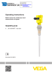
Radar sensor for continuous level
measurement of liquids
VEGAPULS 66
Foundation Fieldbus
Enamelled version
Document ID: 36530
Contents
Contents
About this document
1.1 Function ........................................................................................................................... 4
1.2 Target group ..................................................................................................................... 4
1.3 Symbolism used ............................................................................................................... 4
2
For your safety
2.1 Authorised personnel ....................................................................................................... 5
2.2 Appropriate use ................................................................................................................ 5
2.3 Warning about incorrect use............................................................................................. 5
2.4 General safety instructions ............................................................................................... 5
2.5 CE conformity................................................................................................................... 6
2.6 NAMUR recommendations .............................................................................................. 6
2.7 Radio license for Europe .................................................................................................. 6
2.8 Radio license for USA/Canada ......................................................................................... 6
2.9 Environmental instructions ............................................................................................... 7
3
Product description
3.1 Configuration .................................................................................................................... 8
3.2 Principle of operation........................................................................................................ 9
3.3 Packaging, transport and storage ................................................................................... 10
3.4 Accessories and replacement parts ............................................................................... 10
4
Mounting
4.1 General instructions ....................................................................................................... 13
4.2 Mounting instructions ..................................................................................................... 13
5
Connecting to the bus system
5.1 Preparing the connection ............................................................................................... 22
5.2 Connecting ..................................................................................................................... 23
5.3 Wiring plan, single chamber housing.............................................................................. 25
5.4 Wiring plan, double chamber housing ............................................................................ 25
5.5 Wiring plan, double chamber housing Ex d ia ................................................................ 27
5.6 Double chamber housing with DIS-ADAPT .................................................................... 28
5.7 Wiring plan - version IP 66/IP 68, 1 bar........................................................................... 29
5.8 Switch-on phase............................................................................................................. 29
6
Set up with the display and adjustment module
6.1 Insert display and adjustment module ............................................................................ 30
6.2 Adjustment system ......................................................................................................... 31
6.3 Parameter adjustment .................................................................................................... 32
6.4 Saving the parameter adjustment data ........................................................................... 45
7
Setup with PACTware
7.1 Connect the PC .............................................................................................................. 47
7.2 Parameter adjustment .................................................................................................... 47
7.3 Saving the parameter adjustment data ........................................................................... 48
8
Set up with other systems
8.1 DD adjustment programs ............................................................................................... 49
8.2 Field Communicator 375, 475 ........................................................................................ 49
9
Diagnosis, asset management and service
9.1 Maintenance .................................................................................................................. 50
2
VEGAPULS 66 • Foundation Fieldbus
36530-EN-140209
1
Contents
9.2
9.3
9.4
9.5
9.6
9.7
Measured value and event memory ............................................................................... 50
Asset Management function ........................................................................................... 51
Rectify faults ................................................................................................................... 55
Exchanging the electronics module ................................................................................ 58
Software update ............................................................................................................. 58
How to proceed if a repair is needed .............................................................................. 59
10 Dismounting
10.1 Dismounting steps.......................................................................................................... 60
10.2 Disposal ......................................................................................................................... 60
36530-EN-140209
11 Supplement
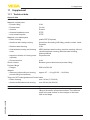
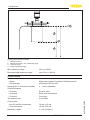
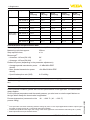
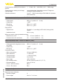
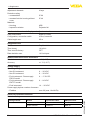
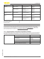
11.1 Technical data ................................................................................................................ 61
11.2 Supplementary information Foundation Fieldbus ........................................................... 67
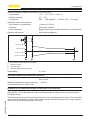
11.3 Dimensions .................................................................................................................... 78
Safety instructions for Ex areas
PleasenotetheEx-specificsafetyinformationforinstallationandoperation in Ex areas. These safety instructions are part of the operating
instructions manual and come with the Ex-approved instruments.
Editing status: 2014-01-28
VEGAPULS 66 • Foundation Fieldbus
3
1 About this document
1
About this document
1.1
Function
1.2
Target group
1.3
Symbolism used
This operating instructions manual provides all the information you
need for mounting, connection and setup as well as important instructionsformaintenanceandfaultrectification.Pleasereadthisinformation before putting the instrument into operation and keep this manual
accessible in the immediate vicinity of the device.
This operating instructions manual is directed to trained specialist
personnel. The contents of this manual should be made available to
these personnel and put into practice by them.
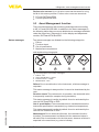
Information, tip, note
This symbol indicates helpful additional information.
Caution: If this warning is ignored, faults or malfunctions can result.
Warning: If this warning is ignored, injury to persons and/or serious
damage to the instrument can result.
Danger: If this warning is ignored, serious injury to persons and/or
destruction of the instrument can result.
•
→
1
Ex applications
This symbol indicates special instructions for Ex applications.
List
The dot set in front indicates a list with no implied sequence.
Action
This arrow indicates a single action.
Sequence of actions
Numbers set in front indicate successive steps in a procedure.
Battery disposal
This symbol indicates special information about the disposal of batteries and accumulators.
36530-EN-140209
4
VEGAPULS 66 • Foundation Fieldbus
2 For your safety
2
2.1
For your safety
Authorised personnel
All operations described in this operating instructions manual must
be carried out only by trained specialist personnel authorised by the
plant operator.
During work on and with the device the required personal protective
equipment must always be worn.
2.2
Appropriate use
VEGAPULS 66 is a sensor for continuous level measurement.
Youcanfinddetailedinformationabouttheareaofapplicationin
chapter "Product description".
Operational reliability is ensured only if the instrument is properly
usedaccordingtothespecificationsintheoperatinginstructions
manual as well as possible supplementary instructions.
2.3
Warning about incorrect use
2.4
General safety instructions
Inappropriate or incorrect use of the instrument can give rise to
application-specifichazards,e.g.vesseloverfillordamagetosystem
components through incorrect mounting or adjustment.
This is a state-of-the-art instrument complying with all prevailing
regulations and guidelines. The instrument must only be operated in a
technicallyflawlessandreliablecondition.Theoperatorisresponsible
for the trouble-free operation of the instrument.
During the entire duration of use, the user is obliged to determine the
compliance of the necessary occupational safety measures with the
current valid rules and regulations and also take note of new regulations.
The safety instructions in this operating instructions manual, the national installation standards as well as the valid safety regulations and
accident prevention rules must be observed by the user.
For safety and warranty reasons, any invasive work on the device
beyond that described in the operating instructions manual may be
carried out only by personnel authorised by the manufacturer. Arbitraryconversionsormodificationsareexplicitlyforbidden.
36530-EN-140209
The safety approval markings and safety tips on the device must also
be observed.
Depending on the instrument version, the emitting frequencies are in
the C or K band range. The low emitting frequencies are far below the
internationally approved limit values. When used correctly, there is no
danger to health.
VEGAPULS 66 • Foundation Fieldbus
5
2 For your safety
2.5
CE conformity
ThedevicefulfillsthelegalrequirementsoftheapplicableECguidelines.ByaffixingtheCEmarking,weconfirmsuccessfultestingofthe
product.
YoucanfindtheCECertificateofConformityinthedownloadsection
of our homepage.
Electromagnetic compatibility
Instruments in four-wire or Ex-d-ia version are designed for use in an
industrial environment. Nevertheless, electromagnetic interference
from electrical conductors and radiated emissions must be taken into
account, as is usual with class A instruments according to EN 613261.Iftheinstrumentisusedinadifferentenvironment,theelectromagnetic compatibility to other instruments must be ensured by suitable
measures.
2.6
NAMUR recommendations
NAMUR is the automation technology user association in the process
industry in Germany. The published NAMUR recommendations are
acceptedasthestandardinfieldinstrumentation.
ThedevicefulfillstherequirementsofthefollowingNAMURrecommendations:
•
•
•
•
NE 21 – Electromagnetic compatibility of equipment
NE 43 – Signal level for malfunction information from measuring
transducers
NE53–Compatibilityoffielddevicesanddisplay/adjustment
components
NE107–Self-monitoringanddiagnosisoffielddevices
For further information see www.namur.de.
2.7
Radio license for Europe
2.8
Radio license for USA/Canada
The instrument is approved according to EN 302372-1/2 (2006-04)
for use in closed vessels.
The instrument is in conformity with part 15 of the FCC regulations.
Take note of the following two regulations:
•
•
The instrument must not cause any interfering emissions
The device must be insensitive to interfering immissions, including
those that may cause undesirable operating conditions
Modificationsnotexpresslyapprovedbythemanufacturerwillleadto
expiry of the operating licence according to FCC/IC.
The instrument may only be used in closed vessels made of metal,
concrete,orfibre-reinforcedplastic.
6
VEGAPULS 66 • Foundation Fieldbus
36530-EN-140209
The instrument is in conformity with RSS-210 of the IC regulations.
2 For your safety
2.9
Environmental instructions
Protection of the environment is one of our most important duties.
That is why we have introduced an environment management system
with the goal of continuously improving company environmental protection.Theenvironmentmanagementsystemiscertifiedaccording
to DIN EN ISO 14001.
Pleasehelpusfulfillthisobligationbyobservingtheenvironmental
instructions in this manual:
Chapter "Packaging, transport and storage"
Chapter "Disposal"
36530-EN-140209
•
•
VEGAPULS 66 • Foundation Fieldbus
7
3 Product description
3
Type label
Product description
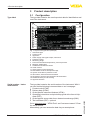
3.1 Configuration
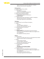
Thetypelabelcontainsthemostimportantdataforidentificationand
use of the instrument:
1
17
16
2
3
15
4
5
6
7
8
9
13
10
11
14
12
Fig. 1: Layout of the type label (example)
1 Instrument type
2 Product code
3 Approvals
4 Power supply and signal output, electronics
5 Protection rating
6 Measuring range
7 Process and ambient temperature, process pressure
8 Material, wetted parts
9 Hardware and software version
10 Order number
11 Serial number of the instrument
12 Data-Matrix-Code for Smartphone-App
13 Symbol of the device protection class
14 ID numbers, instrument documentation
15 Reminder to observe the instrument documentation
16 NotifiedauthorityforCEmarking
17 Approval directive
Serial number - Instrument search
The type label contains the serial number of the instrument. With it
youcanfindthefollowinginstrumentdataonourhomepage:
•
•
•
•
Go to www.vega.com, "VEGATools" and "Instrument search". Enter
the serial number.
Alternatively, you can access the data via your smartphone:
8
VEGAPULS 66 • Foundation Fieldbus
36530-EN-140209
•
•
Product code (HTML)
Delivery date (HTML)
Order-specificinstrumentfeatures(HTML)
Operating instructions and quick setup guide at the time of shipment (PDF)
Order-specificsensordataforanelectronicsexchange(XML)
Testcertificate(PDF)-optional
3 Product description
•
•
•
Scope of this operating
instructions manual
This operating instructions manual applies to the following instrument
versions:
Versions
Theinstrumentisavailableintwodifferentelectronicsversions.Each
versioncanbeidentifiedviatheproductcodeonthetypelabelas
well as on the electronics.
•
•
•
•
Scope of delivery
Application area
Hardware version from 2.1.0
Software version from 4.5.1
Standard electronics type PS60FFC.Electronics with increased sensitivity type PS60FFS.-
The scope of delivery encompasses:
•
•
•
36530-EN-140209
Download the smartphone app "VEGATools" from the "Apple App
Store" or the "GooglePlayStore"
Scan the Data Matrix code on the type label of the instrument or
Enter the serial number manually in the app
Radar sensor
Documentation
– Quick setup guide VEGAPULS 66
– TestcertificateMeasurementaccuracy,dependingonthe
instrument VEGAPULS 66 (optional)
– Operating instructions manual "DIsplay and adjustment module
PLICSCOM" (optional)
– Supplementary instructions "GSM/GPRSradiomodule"
(optional)
– Supplementary instructions manual "Heating for display and
adjustment module" (optional)
– Supplementary instructions manual "Plug connector for continuously measuring sensors" (optional)
– Ex-specific"Safety instructions" (with Ex versions)
– ifnecessary,furthercertificates
DVD "Software & Documents", containing
– Operating instructions
– Safety instructions
– PACTware/DTM-Collection
– Driver software
3.2
Principle of operation
The instrument is suitable for the measurement of liquids under difficultandextremeprocessconditions.Applicationpossibilitiescan
be found in the chemical industry, in environmental and recycling
technology as well as in the petrochemical industry.
The version with enamelled antenna is particularly suitable for measurement of highly corrosive liquids, preferably in enamelled vessels
underdifficultprocessconditionssuchasbuildup,condensationand
foam generation as well as strong product movement.
VEGAPULS 66 • Foundation Fieldbus
9
3 Product description
Theinstrumentcanbeusedwithproductswithanεrvalue≥1.8.The
actually achievable value depends on the measuring conditions, the
antenna system, the standpipe or bypass.
Functional principle
The antenna of the radar sensor emits short radar pulses with a
durationofapprox.1ns.Thesepulsesarereflectedbytheproduct
and received by the antenna as echoes. The transit time of the radar
pulses from emission to reception is proportional to the distance and
hence to the level. The determined level is converted into an appropriate output signal and outputted as measured value.
Packaging
Your instrument was protected by packaging during transport. Its
capacity to handle normal loads during transport is assured by a test
based on ISO 4180.
3.3
Packaging, transport and storage
The packaging of standard instruments consists of environmentfriendly, recyclable cardboard. For special versions, PE foam or PE
foil is also used. Dispose of the packaging material via specialised
recycling companies.
Transport
Transport must be carried out in due consideration of the notes on the
transport packaging. Nonobservance of these instructions can cause
damage to the device.
Transport inspection
The delivery must be checked for completeness and possible transit
damage immediately at receipt. Ascertained transit damage or concealed defects must be appropriately dealt with.
Storage
Up to the time of installation, the packages must be left closed and
stored according to the orientation and storage markings on the
outside.
Unless otherwise indicated, the packages must be stored only under
the following conditions:
Storage and transport
temperature
•
Not in the open
Dry and dust free
Not exposed to corrosive media
Protected against solar radiation
Avoiding mechanical shock and vibration
Storage and transport temperature see chapter "Supplement Technicaldata-Ambientconditions"
Relative humidity 20 … 85 %
3.4
Accessories and replacement parts
The display and adjustment module PLICSCOM is used for measured
value indication, adjustment and diagnosis. It can be inserted into the
sensor or the external display and adjustment unit and removed at
any time.
Youcanfindfurtherinformationintheoperatinginstructions"Display
and adjustment module PLICSCOM" (Document-ID 27835).
10
VEGAPULS 66 • Foundation Fieldbus
36530-EN-140209
PLICSCOM
•
•
•
•
•
•
3 Product description
VEGACONNECT
The interface adapter VEGACONNECT enables the connection of
communication-capable instruments to the USB interface of a PC. For
parameter adjustment of these instruments, the adjustment software
PACTware with VEGA-DTM is required.
Youcanfindfurtherinformationintheoperatinginstructions"Interface
adapterVEGACONNECT" (Document-ID 32628).
VEGADIS 81
The VEGADIS 81 is an external display and adjustment unit for VEGA
plics® sensors.
For sensors with double chamber housing the interface adapter "DISADAPT" is also required for VEGADIS 81.
Youcanfindfurtherinformationintheoperatinginstructions"VEGADIS81" (Document-ID 43814).
DIS-ADAPT
The adapter "DIS-ADAPT" is an accessory part for sensors with
double chamber housings. It enables the connection of VEGADIS 81
to the sensor housing via an M12 x 1 plug.
Youcanfindfurtherinformationinthesupplementaryinstructions
"AdapterDISADAPT" (Document-ID 45250).
PLICSMOBILE T61
The PLICSMOBILE T61 is an external GSM/GPRS radio unit for
transmission of measured values and for remote parameter adjustment of plics® sensors. The adjustment is carried out via PACTware/
DTM by using the integrated USB connection.
Youcanfindfurtherinformationinthesupplementaryinstructions
"PLICSMOBILET61" (Document-ID 37700).
PLICSMOBILE
The PLICSMOBILE is an internal GSM/GPRS radio unit for transmission of measured values and for remote parameter adjustment of
plics® sensors. The adjustment is carried out via PACTware/DTM by
using the integrated USB connection.
Youcanfindfurtherinformationinthesupplementaryinstructions
"PLICSMOBILEGSM/GPRSradiomodule" (Document-ID 36849).
Protective cap
The protective cover protects the sensor housing against soiling and
intense heat from solar radiation.
Youwillfindadditionalinformationinthesupplementaryinstructions
manual "Protective cover" (Document-ID 34296).
Electronics module
The electronics module VEGAPULS series 60 is a replacement part
forradarsensorsofVEGAPULSseries60.Thereisadifferentversion
available for each type of signal output.
36530-EN-140209
Youcanfindfurtherinformationintheoperatinginstructions"ElectronicsmoduleVEGAPULSseries60" (Document-ID 36801).
Supplementary electronics Foundation Fieldbus
The supplementary electronics is a replacement part for the following
sensors with Foundation Fieldbus:
•
•
•
VEGAPULS series 60
VEGAFLEX80series
VEGABAR series 80
VEGAPULS 66 • Foundation Fieldbus
11
3 Product description
Youcanfindfurtherinformationintheoperatinginstructions"Supplementary electronics for Foundation Fieldbus" (Document-ID 45111).
36530-EN-140209
12
VEGAPULS 66 • Foundation Fieldbus
4 Mounting
4
Screwing in
Mounting
4.1
General instructions
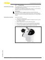
Oninstrumentswithprocessfittingthread,thehexagonmustbetightenedwithasuitablescrewdriver.Wrenchsizeseechapter"Dimensions".
Warning:
The housing must not be used to screw the instrument in! Applying
tightening force can damage internal parts of the housing.
Protection against moisture
Protect your instrument against moisture penetration through the following measures:
•
•
•
•
Use the recommended cable (see chapter "Connecting to power
supply")
Tighten the cable gland
Turn the housing in such a way that the cable gland points downward
Loop the connection cable downward in front of the cable gland
This applies particularly to:
•
•
•
Outdoor mounting
Installations in areas where high humidity is expected (e.g. through
cleaning processes)
Installations on cooled or heated vessels
Suitability for the process Make sure that all parts of the instrument exposed to the process are
conditions
suitable for the existing process conditions.
These are mainly:
•
•
•
Active measuring component
Processfitting
Process seal
•
•
•
•
Process pressure
Process temperature
Chemical properties of the medium
Abrasionandmechanicalinfluences
Process conditions are particularly:
Youcanfindthespecificationsoftheprocessconditionsinchapter
"Technicaldata" as well as on the type label.
36530-EN-140209
Polarisation
4.2
Mounting instructions
The emitted radar impulses of VEGAPULS 66 are electromagnetic
waves. The polarisation is the direction of the electrical share. Their
position is marked on the instrument.
VEGAPULS 66 • Foundation Fieldbus
13
4 Mounting
1
Fig. 2: Position of the polarisation
1
Installation position
Marking hole
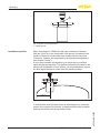
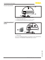
When mounting the VEGAPULS 66, keep a distance of at least
500 mm (19.69 in) to the vessel wall. If the sensor is installed in the
center of dished or round vessel tops, multiple echoes can arise.
These can, however, be suppressed by an appropriate adjustment
(see chapter "Setup").
If you cannot maintain this distance, you should carry out a false
signal storage during setup. This applies particularly if buildup on the
vessel wall is expected. In such a case, it is recommended to repeat
the false signal storage at a later date with existing buildup.
> 500 mm
(19.69")
Fig. 3: Mounting of the radar sensor on round vessel tops
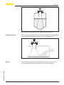
In vessels with conical bottom it can be advantageous to mount the
sensor in the center of the vessel, as measurement is then possible
down to the lowest point of the vessel bottom.
36530-EN-140209
14
VEGAPULS 66 • Foundation Fieldbus
4 Mounting
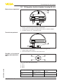
Fig. 4: Mounting of the radar sensor on vessels with conical bottom
Inflowingmedium
Donotmounttheinstrumentsinorabovethefillingstream.Makesure
thatyoudetecttheproductsurface,nottheinflowingproduct.
Fig.5:Mountingoftheradarsensorwithinflowingmedium
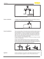
The socket piece should be dimensioned in such a way that the antenna end protrudes at least 10 mm (0.4 in) out of the socket.
36530-EN-140209
Socket
VEGAPULS 66 • Foundation Fieldbus
15
ca. 10 mm
4 Mounting
Fig. 6: Recommended socket mounting
Sensor orientation
In liquids, direct the sensor as perpendicular as possible to the product surface to an achieve optimum measurement.
Fig. 7: Alignment in liquids
Vessel installations
The mounting location of the radar sensor should be a place where no
otherequipmentorfixturescrossthepathofthemicrowavesignals.
Vessel installations, such as e.g. ladders, limit switches, heating spirals, struts, etc., can cause false echoes and impair the useful echo.
Make sure when planning your measuring site that the radar sensor
has a "clear view" to the measured product.
In case of existing vessel installations, a false echo storage should be
carried out during setup.
If large vessel installations such as struts or supports cause false
echoes, these can be attenuated through supplementary measures.
Small,inclinedsheetmetalbafflesabovetheinstallationsscatterthe
radarsignalsandpreventdirectinterferingreflections.
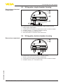
Agitators
16
If there are agitators in the vessel, a false signal suppression should
be carried out with the agitators in motion. This ensures that the
VEGAPULS 66 • Foundation Fieldbus
36530-EN-140209
Fig.8:Coversmoothprofileswithdeflectors
4 Mounting
interferingreflectionsfromtheagitatorsaresavedwiththebladesin
differentpositions.
Fig. 9: Agitators
Foam generation
Throughtheactionoffilling,stirringandotherprocessesinthevessel,
dense foams which considerably damp the emitted signals may form
on the product surface.
If foams are causing measurement errors, the biggest possible radar
antenna should be used.
As an alternative, sensors with guided microwave can be used. These
areunaffectedbyfoamgenerationandarebestsuitedforsuchapplications.
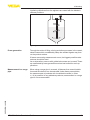
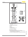
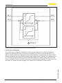
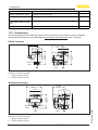
Whenusingasurgepipeinavessel,influencesfromvesselinstallations and turbulences can be excluded. Under these prerequisites,
themeasurementofproductswithlowdielectricvalues(εr value
≥1.6)ispossible.Inveryadhesiveproducts,measurementinasurge
pipe is not recommended.
36530-EN-140209
Measurement in a surge
pipe
VEGAPULS 66 • Foundation Fieldbus
17
4 Mounting
1
2
3
4
100%
5
5
6
7
8
8
10
0%
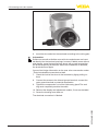
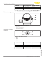
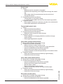
Fig.10:Configurationsurgepipe
1
2
3
4
5
6
7
8
9
Radar sensor
Marking of the polarisation direction
Threadorflangeontheinstrument
Vent hole
Holes
Weld joint
Weldingneckflange
Ball valve with complete opening
Fastening of the surge pipe
18
VEGAPULS 66 • Foundation Fieldbus
36530-EN-140209
Instructions for orientation:
• Note marking of the polarisation plane on the sensor
• Withthreadedfitting,themarkingisonthehexagon,withflange
connectionbetweenthetwoflangeholes
• All holes in the surge pipe must be in one plane with this marking
4 Mounting
Instructions for the measurement:
• The 100 % point must be below the upper vent hole and the
antenna edge
• The 0 % point is the end of the surge pipe
• The tube diameter must be at least DN 40 or 1½" with antenna
size40mm(1½")
• For the parameter adjustment, select "Application standpipe" and
enter the tube diameter to compensate errors due to running time
shift
• A false signal suppression with integrated sensor is recommended
but not mandatory
• The measurement through a ball valve with complete run is possible
Constructional requirements on the surge pipe:
Material metal, smoother inner tube
Preferably pultruded or straight beaded stainless steel tube
Welded joint should be straight and lie in one axis with the holes
Flanges are welded to the tube according to the orientation of the
polarisation level
• Incaseofaextensionwithaweldingneckflangeorpipecollar
as well as when a ball valve is used, the inner surfaces should be
aligned and accurately joined together
• Gapsizewithjunctions≤0.1mm
• Do not weld through the pipe wall. The surge pipe must remain
smooth inside. Roughness and beads on the inside caused by
unintentional penetration should be removed since they cause
strong false echoes and encourage buildup
• Surge pipes must extend all the way down to the requested min.
level, as measurement is only possible within the tube
• Diameterofholes≤5mm,anynumberOK,ononesideorcompletely through
• The antenna diameter of the sensor should correspond to the
inner diameter of the tube
• Diameter should be constant over the complete length
•
•
•
•
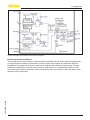
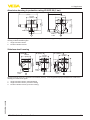
An alternative to measurement in a surge pipe is measurement in a
bypass tube outside of the vessel.
36530-EN-140209
Measurement in the
bypass
VEGAPULS 66 • Foundation Fieldbus
19
4 Mounting
1
2
3
4
100 %
6
5
0%
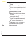
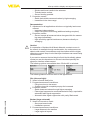
Fig.11:Configurationbypass
1
2
3
4
5
6
Radar sensor
Marking of the polarisation direction
Instrumentflange
Distance sensor reference plane to upper tube connection
Distance of the tube connections
Ball valve with complete opening
Instructions for orientation:
• Note marking of the polarisation plane on the sensor
• Withthreadedfitting,themarkingisonthehexagon,withflange
connectionbetweenthetwoflangeholes
• The pipe connections to the vessel must be in one plane with this
marking
20
VEGAPULS 66 • Foundation Fieldbus
36530-EN-140209
Instructions for the measurement:
The 100 % point must not be above the upper tube connection to
the vessel
• The 0 % point must not be below the lower tube connection to the
vessel
• Min. distance sensor reference plane to the upper edge upper
tube connection > 300 mm
•
4 Mounting
•
•
•
•
The tube diameter must be at least DN 40 or 1½" with antenna
size40mm(1½")
For the parameter adjustment, select "Application standpipe" and
enter the tube diameter to compensate errors due to running time
shift
A false signal suppression with integrated sensor is recommended
but not mandatory
The measurement through a ball valve with complete run is possible
Constructional requirements on the bypass pipe:
Material metal, smoother inner tube
In case of an extremely rough tube inner surface, use an inserted
tube (tube in tube) or a radar sensor with tube antenna
• Flanges are welded to the tube according to the orientation of the
polarisation level
• Gapsizewithjunctions≤0.1mm,forexample,whenusingaball
valveorintermediateflangeswithsinglepipesections
• The antenna diameter of the sensor should correspond to the
inner diameter of the tube
• Diameter should be constant over the complete length
•
•
Mounting in the vessel
insulation
Instruments for a temperature range up to 250 °C or up to 450 °C
haveadistancepiecebetweenprocessfittingandelectronicshousing. Ths distance piece is used for thermal decoupling of the electronics against high process temperatures.
Information:
The distance piece must only be incorporated up to max. 50 mm in
the vessel isolation. Only then, a reliable temperature decoupling is
guaranteed.
36530-EN-140209
max. 50 mm
(1.97")
1
2
3
Fig. 12: Mounting the instrument on insulated vessels.
1 Electronicshousing
2 Distance piece
3 Vessel insulation
VEGAPULS 66 • Foundation Fieldbus
21
5 Connecting to the bus system
5
Safety instructions
Connecting to the bus system
5.1
Preparing the connection
Always keep in mind the following safety instructions:
•
•
Connect only in the complete absence of line voltage
If overvoltage surges are expected, overvoltage arresters should
be installed
Voltage supply
The instrument requires a operating voltage of 9 … 32 V DC. Operating voltage and the digital bus signal are carried on the same two-wire
connection cable. Power is supplied via the H1 power supply.
Connection cable
Connection is carried out with screened cable according to Fieldbus
specification.
Use cable with round cross-section. A cable outer diameter of
5…9mm(0.2…0.35in)ensuresthesealeffectofthecablegland.
Ifyouareusingcablewithadifferentdiameterorcross-section,
exchange the seal or use a suitable cable gland.
Make sure that the entire installation is carried out according to the
Fieldbusspecification.Inparticular,makesurethatthebusisterminated with suitable terminating resistors.
Cable gland ½ NPT
With plastic housing, the NPT cable gland or the Conduit steel tube
must be screwed without grease into the threaded insert.
Max. torque for all housings see chapter "Technicaldata".
Cable screening and
grounding
Make sure that the cable screening and ground is executed accordingtotheFielbusspecification.Ifelectromagneticinterferenceis
expected which is above the test values of EN 61326-1 for industrial
areas, we recommend to connect the cable screen on both ends to
ground potential.
In systems with potential equalisation, connect the cable screen
directly to ground potential at the power supply unit, in the connection
box and at the sensor. The screen in the sensor must be connected
directly to the internal ground terminal. The ground terminal outside
on the housing must be connected to the potential equalisation (low
impedance).
22
VEGAPULS 66 • Foundation Fieldbus
36530-EN-140209
In systems without potential equalisation with cable screening on
both sides, connect the cable screen directly to ground potential at
the power supply unit and at the sensor. In the connection box or
T-distributor, the screen of the short stub to the sensor must not be
connected to ground potential or to another cable screen. The cable
screens to the power supply unit and to the next distributor must be
connected to each other and also connected to ground potential via a
ceramic capacitor (e.g. 1 nF, 1500 V). Low-frequency potential equalisationcurrentsarethussuppressed,buttheprotectiveeffectagainst
high frequency interference signals remains.
5 Connecting to the bus system
Connection technology
5.2
Connecting
The voltage supply and signal output are connected via the springloaded terminals in the housing.
Connection to the display and adjustment module or to the interface
adapter is carried out via contact pins in the housing.
Information:
The terminal block is pluggable and can be removed from the
electronics. To do this, lift the terminal block with a small screwdriver
and pull it out. When reinserting the terminal block, you should hear it
snap in.
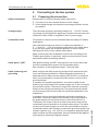
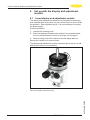
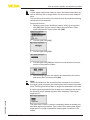
Connection procedure
Proceed as follows:
1. Unscrew the housing cover
2. If a display and adjustment module is installed, remove it by turning it slightly to the left.
3. Loosen compression nut of the cable entry gland
4. Remove approx. 10 cm (4 in) of the cable mantle, strip approx.
1 cm (0.4 in) of insulation from the ends of the individual wires
5. Insert the cable into the sensor through the cable entry
36530-EN-140209
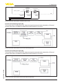
Fig. 13: Connection steps 5 and 6 - Single chamber housing
VEGAPULS 66 • Foundation Fieldbus
23
5 Connecting to the bus system
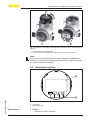
Fig. 14: Connection steps 5 and 6 - Double chamber housing
6. Insert the wire ends into the terminals according to the wiring plan
Information:
Solidcoresaswellasflexiblecoreswithwireendsleevesareinserteddirectlyintotheterminalopenings.Incaseofflexiblecoreswithout
end sleeves, press the terminal from above with a small screwdriver,
the terminal opening is then free. When the screwdriver is released,
the terminal closes again.
Youcanfindfurtherinformationonthemax.wirecross-sectionunder
"Technicaldata/Electromechanicaldata"
7. Check the hold of the wires in the terminals by lightly pulling on
them
8. Connect the screen to the internal ground terminal, connect the
outer ground terminal to potential equalisation
9. Tighten the compression nut of the cable entry gland. The seal
ring must completely encircle the cable
10. Reinsert the display and adjustment module, if one was installed
11. Screw the housing cover back on
Theelectricalconnectionisfinished.
36530-EN-140209
24
VEGAPULS 66 • Foundation Fieldbus
5 Connecting to the bus system
Electronics and terminal
compartment
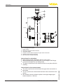
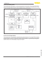
5.3
Wiring plan, single chamber housing
2
3
4
1
1
0
0
Bus
(+)1
2(-)
5
6
7
8
5
1
Fig.15:Electronicsandterminalcompartment,singlechamberhousing
1
2
3
4
5
Electronics compartment
Voltage supply, signal output
Contact pins for the display and adjustment module or interface adapter
Simulation switch ("1" = mode for simulation release)
For external display and adjustment unit
Groundterminalforconnectionofthecablescreen
5.4
Wiring plan, double chamber housing
2
3
1
1
0
0
Bus
(+)1
2(-)
1
5
6
7
8
1
Fig.16:Electronicscompartment,doublechamberhousing
Internal connection to the connection compartment
Contact pins for the display and adjustment module or interface adapter
Simulation switch ("on" = simulation mode)
36530-EN-140209
1
2
3
VEGAPULS 66 • Foundation Fieldbus
25
5 Connecting to the bus system
Terminal compartment
2
Bus
(+)1
3
2(-)
1
Fig.17:Terminalcompartment,doublechamberhousing
1 Voltage supply, signal output
2 For display and adjustment module or interface adapter
3 Groundterminalforconnectionofthecablescreen
Connection compartment
- Radio module PLICSMOBILE
SIM-Card
Status
Test
USB
(+)1
2(-)
1
Fig.18:ConnectioncompartmentradiomodulePLICSMOBILE
1
Voltage supply
Youcanfinddetailedinformationonconnectioninthesupplementary
instructions "PLICSMOBILEGSM/GPRSradiomodule".
36530-EN-140209
26
VEGAPULS 66 • Foundation Fieldbus
5 Connecting to the bus system
Electronics compartment
5.5
Wiring plan, double chamber housing Ex d ia
2
3
1
1
0
0
Bus
(+)1
2(-)
1
5
6
7
8
1
Fig.19:Electronicscompartment,doublechamberhousing
1
2
3
Internal connection to the connection compartment
Contact pins for the display and adjustment module or interface adapter
Simulation switch ("on" = simulation mode)
Terminal compartment
Bus
(+)1
2
2(-)
1
Fig.20:Connectioncompartment,doublechamberhousingExdia
1 Voltage supply, signal output
2 Groundterminalforconnectionofthecablescreen
Plug M12 x 1 for external
display and adjustment
unit
4
3
1
2
Fig.21:Topviewoftheplugconnector
36530-EN-140209
1
2
3
4
Pin 1
Pin 2
Pin 3
Pin 4
Contact pin
Colour connection cable in the sensor
Terminal, electronics
module
Pin 1
Brown
5
Pin 2
White
6
VEGAPULS 66 • Foundation Fieldbus
27
5 Connecting to the bus system
Electronics compartment
Contact pin
Colour connection cable in the sensor
Terminal, electronics
module
Pin 3
Blue
7
Pin 4
Black
8
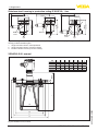
5.6
Double chamber housing with DIS-ADAPT
1
2
3
Fig. 22: View to the electronics compartment
1 DIS-ADAPT
2 Internal plug connection
3 Plug connector M12 x 1
Assignment of the plug
connector
4
3
1
2
Fig.23:Topviewoftheplugconnector
1
2
3
4
Pin 1
Pin 2
Pin 3
Pin 4
Contact pin
Colour connection cable in the sensor
Terminal, electronics
module
Pin 1
Brown
5
Pin 2
White
6
Pin 3
Blue
7
Pin 4
Black
8
36530-EN-140209
28
VEGAPULS 66 • Foundation Fieldbus
5 Connecting to the bus system
Wire assignment, connection cable
5.7
Wiring plan - version IP 66/IP 68, 1 bar
1
2
Fig. 24: Wire assignment in permanently connected connection cable
1
2
brown (+) and blue (-) to power supply or to the processing system
Shielding
5.8
Switch-on phase
After VEGAPULS 66 is connected to the bus system, the instrument
carries out a self-test for approx. 30 seconds. The following steps are
carried out:
•
•
•
•
Internal check of the electronics
Indication of the instrument type, hardware and software version,
measurement loop name on the display or PC
Indication of the status message "F 105 Determine measured
value" on the display or PC
Statusbytegoesbrieflytofaultvalue
36530-EN-140209
As soon as a plausible measured value is found, it is outputted to the
signal cable. The value corresponds to the actual level as well as the
settings already carried out, e.g. factory settings.
VEGAPULS 66 • Foundation Fieldbus
29
6 Set up with the display and adjustment module
6
6.1
Set up with the display and adjustment
module
Insert display and adjustment module
The display and adjustment module can be inserted into the sensor
andremovedagainatanytime.Youcanchooseanyoneoffourdifferent positions - each displaced by 90°. It is not necessary to interrupt
the power supply.
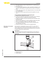
Proceed as follows:
1. Unscrew the housing cover
2. Place the display and adjustment module in the requested position onto the electronics and turn to the right until it snaps in
3. Screw housing cover with inspection window tightly back on
Removal is carried out in reverse order.
The display and adjustment module is powered by the sensor, an additional connection is not necessary.
Fig. 25: Installing the display and adjustment module in the electronics compartment of the single chamber housing
36530-EN-140209
30
VEGAPULS 66 • Foundation Fieldbus
6 Set up with the display and adjustment module
1
2
Fig. 26: Insertion of the display and adjustment module into the double chamber
housing
1 In the electronics compartment
2 Intheconnectioncompartment(withEx-d-iaversionnotpossible)
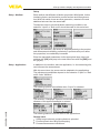
Note:
Ifyouintendtoretrofittheinstrumentwithadisplayandadjustment
module for continuous measured value indication, a higher cover with
an inspection glass is required.
6.2
Adjustment system
1
36530-EN-140209
2
Fig. 27: Display and adjustment elements
Key functions
1
2
LC display
Adjustment keys
•
[OK] key:
– Move to the menu overview
VEGAPULS 66 • Foundation Fieldbus
31
6 Set up with the display and adjustment module
•
•
•
Adjustment system
– Confirmselectedmenu
– Edit parameter
– Save value
[-] key:
– Presentation, change measured value
– Select list entry
– Select editing position
[+] key:
– Change value of the parameter
[ESC] key:
– Interrupt input
– Jump to next higher menu
The device is adjusted via the four keys of the display and adjustment
module. The LC display indicates the individual menu items. The
functions of the individual keys are shown in the above illustration. Approx. 60 minutes after the last pressing of a key, an automatic reset to
measuredvalueindicationistriggered.Anyvaluesnotconfirmedwith
[OK] will not be saved.
6.3
Parameter adjustment
The instrument is adapted to the application conditions via the parameter adjustment. The parameter adjustment is carried out with an
adjustment menu.
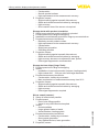
Main menu
Themainmenuisdividedintofivesectionswiththefollowingfunctions:
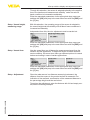
Setup: Settings, for example, for medium, application, vessel, adjustment, damping
Display: Language setting, settings for the measured value indication
as well as lighting
Diagnosis: Information, e.g. on instrument status, pointer, measurement reliability, simulation, echo curve
Further settings: e.g. instrument units, unit SV 2, false signal suppression,linearization,date/time,reset,copysensordata
Info: Instrument name, hardware and software version, date of manufacture, device ID, instrument features
32
VEGAPULS 66 • Foundation Fieldbus
36530-EN-140209
In the main menu point "Setup", the individual submenu points
should be selected one after the other and provided with the correct
parameters to ensure optimum adjustment of the measurement. The
procedure is described in the following.
6 Set up with the display and adjustment module
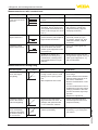
Setup
Setup - Medium
Eachmediumhasdifferentreflectionproperties.Withliquids,further
interferingfactorsarefluctuationproductsurfaceandfoamgeneration. With bulk solids, these are dust generation, material cone and
additional echoes from the vessel wall.
Toadaptthesensortothesedifferentmeasuringconditions,the
selection "Liquid" or "Bulk solid" should be made in this menu item.
Through this selection, the sensor is adapted perfectly to the product
andmeasurementreliability,particularlyinproductswithpoorreflective properties, is considerably increased.
Enter the requested parameters via the appropriate keys, save your
settings with [OK] and jump to the next menu item with the [ESC] and
the [->] key.
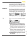
Setup - Application
In addition to the medium, also the application, i.e. the measuring site,
caninfluencethemeasurement.
With this menu item, the sensor can be adapted to the applications.
The adjustment possibilities depend on the selection "Liquid" or "Bulk
solid" under "Medium".
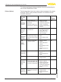
The following options are available when "Liquid" is selected:
36530-EN-140209
The selection "Standpipe" opens a new window in which the inner
diameter of the applied standpipe is entered.
The following features form the basis of the applications:
Storage tank:
• Setup: large-volumed, upright cylindrical, spherical
• Productspeed:slowfillingandemptying
• Process/measurement conditions:
VEGAPULS 66 • Foundation Fieldbus
33
6 Set up with the display and adjustment module
•
– Condensation
– Smooth product surface
– High requirements to the measurement accuracy
Properties, sensor:
– Slight sensitivity against sporadic false echoes
– Stable and reliable measured values by averaging
– High accuracy
– Short reaction time of the sensor not required
Storage tanke with product circulation:
Setup: large-volumed, upright cylindrical, spherical
Productspeed:slowfillingandemptying
Installations: small laterally mounted or large top mounted stirrer
Process/measurement conditions:
– Relatively smooth product surface
– High requirements to the measurement accuracy
– Condensation
– Slight foam generation
– Overfillingpossible
• Properties, sensor:
– Slight sensitivity against sporadic false echoes
– Stable and reliable measured values by averaging
– High accuracy because not adjusted for max. speed
– False signal suppression recommended
•
•
•
•
Storage tank on ships (Cargo Tank):
Productspeed:slowfillingandemptying
Vessel:
– Installations in the bottom section (bracers, heating spirals)
– High sockets 200 … 500 mm, also with large diameters
• Process/measurement conditions:
– Condensation, buildup by movement
– Max. requirement on measurement accuracy from 95 %
• Properties, sensor:
– Slight sensitivity against sporadic false echoes
– Stable and reliable measured values by averaging
– High accuracy
– False signal suppression required
•
•
Stirrer vessel (reactor):
Setup:allvesselsizespossible
Product speed:
– Fasttoslowfillingpossible
– Vesselisveryoftenfilledandemptied
• Vessel:
– Socket available
– Large agitator blades of metal
– Vortex breakers, heating spirals
• Process/measurement conditions:
– Condensation, buildup by movement
– Strong spout generation
– Very agitated surface, foam generation
• Properties, sensor:
•
•
VEGAPULS 66 • Foundation Fieldbus
36530-EN-140209
34
6 Set up with the display and adjustment module
– Higher measurement speed through lower averaging
– Sporadic false echoes are suppressed
Dosing vessel:
Setup:allvesselsizespossible
Product speed:
– Fastfillingandemptying
– Vesselisveryoftenfilledandemptied
• Vessel: narrow installation situation
• Process/measurement conditions:
– Condensation, buildup on the antenna
– Foam generation
• Properties, sensor:
– Measurementspeedoptimizedbyvirtuallynoaveraging
– Sporadic false echoes are suppressed
– False signal suppression recommended
•
•
Standpipe:
Productspeed:veryfastfillingandemptying
Vessel:
– Vent hole
– Joinslikeflanges,weldjoints
– Shifting of the running time in the tube
• Process/measurement conditions:
– Condensation
– Buildup
• Properties, sensor:
– Measurementspeedoptimizedthroughlittleaveraging
– Entering the tube inside diameter takes the running time shift
into consideration
– Echo detection sensitivity reduced
•
•
Bypass:
Product speed:
– Fastuptoslowfillingwithshortuptolongbypasstubepossible
– Often the level is hold via a control facility
• Vessel:
– Lateral outlets and inlets
– Joinslikeflanges,weldjoints
– Shifting of the running time in the tube
• Process/measurement conditions:
– Condensation
– Buildup
– Separation of oil and water possible
– Overfillingintotheantennapossible
• Properties, sensor:
– Measurementspeedoptimizedthroughlittleaveraging
– Entering the tube inside diameter takes the running time shift
into consideration
– Echo detection sensitivity reduced
– False signal suppression recommended
36530-EN-140209
•
VEGAPULS 66 • Foundation Fieldbus
35
6 Set up with the display and adjustment module
Plastic tank:
• Vessel:
– Measurementfixmountedorintegrated
– Measurement depending on the application through the vessel
top
– With empty vessel, the measurement can be carried out
through the bottom
• Process/measurement conditions:
– Condensation on the plastic ceiling
– In outside facilities water and snow on the vessel top possible
• Properties, sensor:
– False signals outside the vessel are not taken into consideration
– False signal suppression recommended
Transportable plastic tank:
Vessel:
– Materialandthicknessdifferent
– Measurement through the vessel top
• Process/measurement conditions:
– Measured value jump with vessel change
• Properties, sensor:
– Quickadaptationtochangingreflectionconditionsthrough
vessel change
– False signal suppression required
•
Open water (gauge measurement):
Gauge rate of change: slow gauge change
Process/measurement conditions:
– Distance sensor to water surface to big
– Extreme damping of output signal due to wave generation
– Ice and condensation on the antenna possible
– Spiders and insect nestle in the antennas
– Floating material and animals sporadically on the water surface
• Properties, sensor:
– Stable and reliable measured values by high averaging
– Insensitive in the close range
•
•
Openflume(flowmeasurement):
Gauge rate of change: slow gauge change
Process/measurement conditions:
– Ice and condensation on the antenna possible
– Spiders and insect nestle in the antennas
– Smooth water surface
– Exact measurement result required
– Distance to the water surface normally relatively high
• Properties, sensor:
– Stable and reliable measured values by high averaging
– Insensitive in the close range
•
•
36
VEGAPULS 66 • Foundation Fieldbus
36530-EN-140209
Rain water overfall (weir):
Gauge rate of change: slow gauge change
Process/measurement conditions:
– Ice and condensation on the antenna possible
•
•
6 Set up with the display and adjustment module
•
– Spiders and insect nestle in the antennas
– Turbulent water surface
– Sensorfloodingpossible
Properties, sensor:
– Stable and reliable measured values by high averaging
– Insensitive in the close range
Demonstration:
Adjustment for all applications which are not typically level measurement
– Instrument demonstration
– Object recognition/monitoring (additional settings required)
• Properties, sensor:
– Sensor accepts all measured value changes within the measuring range immediately
– High sensitivity against interferences, because virtually no
averaging
•
Caution:
Ifaseparationofliquidswithdifferentdielectricconstantoccursin
the vessel, for example through condensation, the radar sensor can
detect under certain circumstances only the medium with the higher
dielectric constant. Keep in mind that layer interfaces can cause faulty
measurements.
If you want to measure the total height of both liquids reliably, please
contact our service department or use an instrument specially designed for interface measurement.
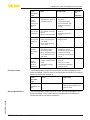
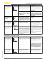
The following options are available when "Bulk solid" is selected:
The following features form the basis of the applications:
36530-EN-140209
Silo (slim and high):
• Vessel of metal: weld joints
• Process/measurement conditions:
– Filling too close to the sensor
– System noise with completely empty silo increased
• Properties, sensor:
– Stable measured values through higher averaging
– False signal suppression recommended with setup, required for
automatic false signal suppression
– Automaticfalsesignalsuppressionwithpartlyfilledvessel
Bunker (large-volumed):
Vessel of concrete or metal:
– Structured vessel walls
– Installations present
• Process/measurement conditions:
– Large distance to the medium
– Large angles of repose
•
VEGAPULS 66 • Foundation Fieldbus
37
6 Set up with the display and adjustment module
•
Properties, sensor:
– Mean averaging
– High measured value jumps are accepted
Bunkerwithfastfilling:
Vessel of concrete or metal, also multiple chamber silo:
– Structured vessel walls
– Installations present
• Process/measurement conditions:
– Measured value jumps, e.g. by truck loading
– Large distance to the medium
– Large angles of repose
• Properties, sensor:
– Lower averaging
– Very high measured value jumps are accepted
•
Heap:
Sensor mounting on movable conveyor belts
Detectionoftheheapprofile
Heightdetectionduringfilling
Process/measurement conditions:
– Measuredvaluejumps,e.g.bytheprofileoftheheaportraverses
– Large angles of repose
– Measurementnearthefillingstream
• Properties, sensor:
– Mean averaging
– High measured value jumps are accepted
•
•
•
•
Crusher:
Vessel: installations, wear and protective facilities available
Process/measurement conditions:
– Measured value jumps, e.g. by truck loading
– Fast reaction time
– Large distance to the medium
• Properties, sensor:
– Little averaging
– Max. reaction speed, very high measured value jumps are
accepted
•
•
Demonstration:
Adjustment for all applications which are not typically level measurement
– Instrument demonstration
– Object recognition/monitoring (additional settings required)
• Properties, sensor:
– Sensor accepts all measured value changes within the measuring range immediately
– High sensitivity against interferences, because virtually no
averaging
•
VEGAPULS 66 • Foundation Fieldbus
36530-EN-140209
38
6 Set up with the display and adjustment module
Through this selection, the sensor is adapted optimally to the application or the location and measurement reliability under the various
basic conditions is increased considerably.
Enter the requested parameters via the appropriate keys, save your
settings with [OK] and jump to the next menu item with the [ESC] and
the [->] key.
Setup - Vessel height,
measuring range
With this selection, the operating range of the sensor is adapted to
thevesselheightandthereliabilitywithdifferentframeconditionsis
increased considerably.
Independent from this, the min. adjustment must be carried out.
Enter the requested parameters via the appropriate keys, save your
settings with [OK] and jump to the next menu item with the [ESC] and
the [->] key.
Setup - Vessel form
Alsothevesselformcaninfluencethemeasurementapartfromthe
medium and the application. To adapt the sensor to these measurementconditions,thismenuitemoffersyoudifferentoptionsforvessel
bottom and ceiling in case of certain applications.
Enter the requested parameters via the appropriate keys, save your
settings with [OK] and jump to the next menu item with the [ESC] and
the [->] key.
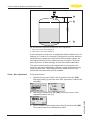
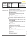
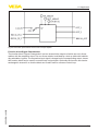
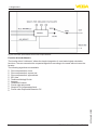
Setup - Adjustment
Since the radar sensor is a distance measuring instrument, the
distance from the sensor to the product surface is measured. For
indication of the real level, an allocation of the measured distance to
the percentage height must be carried out.
36530-EN-140209
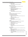
To perform the adjustment, enter the distance with full and empty vessel, see the following example:
VEGAPULS 66 • Foundation Fieldbus
39
3
100%
2
15 m
(590.6")
1,5 m
(59.1")
6 Set up with the display and adjustment module
0%
1
Fig.28:Parameteradjustmentexamplemin./max.adjustment
1
2
Min. level = max. meas. distance
Max. level = min. meas. distance
If these values are not known, an adjustment with the distances of for
example 10 % and 90 % is possible. Starting point for these distance
specificationsisalwaysthesealsurfaceofthethreadorflange.You
canfindspecificationsofthereferenceplaneinchapter"Technical
data". By means of these settings, the real level will be calculated.
The real product level during this adjustment is not important, because the min./max. adjustment is always carried out without changing the product level. These settings can be made ahead of time
without the instrument having to be installed.
Setup - Min. adjustment
Proceed as follows:
1. Select the menu item "Setup" with [->]andconfirmwith[OK].
Now select with [->] the menu item "Min. adjustment"andconfirm
with [OK].
2. Edit the percentage value with [OK] and set the cursor to the
requested position with [->].
40
VEGAPULS 66 • Foundation Fieldbus
36530-EN-140209
3. Set the requested percentage value with [+] and save with [OK].
The cursor jumps now to the distance value.
6 Set up with the display and adjustment module
4. Enter the suitable distance value in m for the empty vessel (e.g.
distance from the sensor to the vessel bottom) corresponding to
the percentage value.
5. Save settings with [OK] and move with [ESC] and [->] to the max.
adjustment.
Setup - Max. adjustment
Proceed as follows:
1. Select with [->]themenuitem"Max.adjustment"andconfirm
with [OK].
2. Prepare the percentage value for editing with [OK] and set the
cursor to the requested position with [->].
3. Set the requested percentage value with [+] and save with [OK].
The cursor jumps now to the distance value.
4. Enter the appropriate distance value in m (corresponding to the
percentage value) for the full vessel. Keep in mind that the max.
level must lie below the min. distance to the antenna edge.
5. Save settings with [OK]
36530-EN-140209
Diagnosis - Peak value
The respective min. and max. measured value is saved in the sensor.
The values are displayed in the menu item "Peak values".
Diagnosis - Measurement When non-contact level sensors are used, the measurement can be
reliability
influencedbytherespectiveprocessconditions.Inthismenuitem,
the measurement reliability of the level echo is displayed as dB value.
The measurement reliability equals signal strength minus noise. The
higher the value, the more reliable the measurement. With a functioning measurement, the values are > 10 dB.
VEGAPULS 66 • Foundation Fieldbus
41
6 Set up with the display and adjustment module
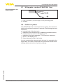
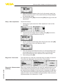
Diagnoses - Curve indica- The "Echocurve" shows the signal strength of the echoes over the
tion
measuring range in dB. The signal strength enables an evaluation of
the quality of the measurement.
The "False signal suppression" displays the saved false echoes (see
menu "Additional settings") of the empty vessel with signal strength in
"dB" over the measuring range.
A comparison of echo curve and false signal suppression allows a
more detailed statement of the reliability.
Theselectedcurveispermanentlyupdated.Asubmenuwithzoom
functions is opened with the [OK] key:
•
•
•
Diagnostics - Echo curve
memory
"X-Zoom":Zoomfunctionforthemeas.distance
"Y-Zoom":1,2,5and10xsignalmagnificationin"dB"
"Unzoom":Resetthepresentationtothenominalmeasuringrange
withsinglemagnification
With the function "Echocurvememory" the echo curve can be saved
at the time of setup. This is generally recommended; for using the Asset Management functions it is absolutely necessary. If possible, the
curve should be saved with a low level in the vessel.
With the adjustment software PACTware and the PC, the high resolutionechocurvecanbedisplayedandusedtorecognizesignal
changes over the operating time. In addition, the echo curve of the
setup can be also displayed in the echo curve window and compared
with the actual echo curve.
42
Thefollowingcircumstancescauseinterferingreflectionsandcan
influencethemeasurement:
•
•
•
•
High sockets
Vessel installations such as struts
Agitators
Buildup or welded joints on vessel walls
VEGAPULS 66 • Foundation Fieldbus
36530-EN-140209
Additional adjustments False signal suppression
6 Set up with the display and adjustment module
Note:
A false signal suppression detects, marks and saves these false signals so that they are no longer taken into account for level measurement.
This should be done with the low level so that all potential interfering
reflectionscanbedetected.
Proceed as follows:
1. Select the menu item "Additional settins" with [->]andconfirm
with [OK]. With [->] you have to select the menu item "False
signal suppression"andconfirmwith[OK].
2. Confirmagainwith[OK].
3. Confirmagainwith[OK].
4. Confirmagainwith[OK] and enter the actual distance from the
sensor to the product surface.
5. All interfering signals in this section are detected by the sensor
andstoredafterconfirmingwith[OK].
Note:
Check the distance to the product surface, because if an incorrect
(too large) value is entered, the existing level will be saved as a false
echo.Thefillinglevelwouldthennolongerbedetectableinthisarea.
36530-EN-140209
If a false signal suppression has already been created in the sensor,
the following menu window appears when selecting "False signal
suppression":
The menu item "Delete" is used to completely delete an already created false signal suppression. This is useful if the saved false signal
suppression no longer matches the metrological conditions in the
vessel.
VEGAPULS 66 • Foundation Fieldbus
43
6 Set up with the display and adjustment module
The menu item "Extend" is used to extend an already created false
signal suppression. This is useful if a false signal suppression was
carried out with a too high level and not all false signals could be detected. When selecting "Extend", the distance to the product surface
of the created false signal suppression is displayed. This value can
now be changed and the false signal suppression can be extended to
this range.
Additional adjustments Linearization curve
A linearisation is necessary for all vessels in which the vessel volume
doesnotincreaselinearlywiththelevel-e.g.inahorizontalcylindrical or spherical tank - and the indication or output of the volume is
required. Corresponding linearisation curves are preprogrammed for
these vessels. They represent the correlation between the level percentage and vessel volume. By activating the appropriate curve, the
volume percentage of the vessel is displayed correctly. If the volume
should not be displayed in percent but e.g. in l or kg, a scaling can be
also set in the menu item "Display".
Enter the requested parameters via the appropriate keys, save your
settings and jump to the next menu item with the [ESC] and [->] key.
Additional adjustments
- Reset
When a reset is carried out, all settings (with only a few exceptions)
are reset. The exceptions are: PIN, language, lighting, SIL and HART
mode.
The following reset functions are available:
•
•
•
44
VEGAPULS 66 • Foundation Fieldbus
36530-EN-140209
•
Delivery status: Restoring the parameter settings at the time
of shipment from the factory. A created false signal suppression,
user-programmablelinearizationcurve,measuredvaluememory
as well as event memory will be deleted.
Basic settings: Resetting of the parameter settings incl. special
parameters to the default values of the respective instrument. Any
createdfalsesignalsuppression,userprogrammablelinearization
curve, measured value memory as well as event memory will be
deleted.
Setup: Resetting of the parameter settings to the default values of
the respective instrument . Order-related settings remain but are
not taken over into the current parameters. User-generated false
signalsuppression,user-programmedlinearizationcurve,measured value memory, echo curve memory as well as event memory
remainuntouched.Thelinearizationissettolinear.
False signal suppression: Deleting a previously created false
signal suppression. The false signal suppression created in the
factory remains active.
6 Set up with the display and adjustment module
•
Peak values measured value: Resetting of the measured min.
and max. distances to the actual measured value.
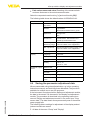
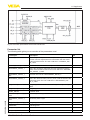
Select the requested reset function [->]andconfirmwith[OK].
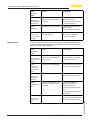
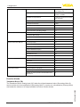
The following table shows the default values of VEGAPULS 66:
Menu section
Menu item
Default value
Setup
Measurement
loop name
Sensor
Medium
Liquid/Water
Application
Storage tank
Vessel form
Vessel bottom, dished boiler end
Vesell height/
Measuring range
Recommended measuring range, see
"Technicaldata" in the supplement
Min. adjustment
Recommended measuring range, see
"Technicaldata" in the supplement
Display
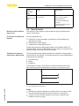
Additional adjustments
6.4
Bulk solids/Crushed stones, gravel
Silo
Vessel top, dished boiler end
Damping
0.0 s
Language
Like order
Displayed value
Distance
Display unit
m(d)
Scaling
0.00 %, 0 l
Distance unit
m
Temperature unit
°C
Unit SV2
m
Probe length
Length of the standpipe Ex factory
Linearisation
curve
Linear
100.00 %, 100 l
Saving the parameter adjustment data
36530-EN-140209
We recommended noting the adjusted data, e.g. in this operating
instructions manual, and archiving them afterwards. They are thus
available for multiple use or service purposes.
If the instrument is equipped with a display and adjustment module,
the data in the sensor can be saved in the display and adjustment
module. The procedure is described in the operating instructions
manual "Display and adjustment module" in the menu item "Copy
sensor data". The data remain there permanently even if the sensor
power supply fails.
The following data or settings for adjustment of the display and adjustment module are saved:
•
All data of the menu "Setup" and "Display"
VEGAPULS 66 • Foundation Fieldbus
45
6 Set up with the display and adjustment module
•
•
In the menu "Additional adjustments" the items "Sensor-specific
units, temperature unit and linearization"
Thevaluesoftheuserprogrammablelinearizationcurve
The function can also be used to transfer settings from one instrument to another instrument of the same type. If it is necessary to
exchange a sensor, the display and adjustment module is inserted
into the replacement instrument and the data are likewise written into
the sensor via the menu item "Copy sensor data".
36530-EN-140209
46
VEGAPULS 66 • Foundation Fieldbus
7 Setup with PACTware
7
7.1
Setup with PACTware
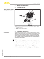
Connect the PC
Via the interface adapter
directly on the sensor
2
1
3
Fig. 29: Connection of the PC directly to the sensor via the interface adapter
1 USBcabletothePC
2 InterfaceadapterVEGACONNECT
3 Sensor
Prerequisites
7.2
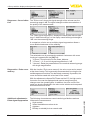
Parameter adjustment
For parameter adjustment of the sensor via a Windows PC, the configurationsoftwarePACTwareandasuitableinstrumentdriver(DTM)
according to FDT standard are required. The up-to-date PACTware
version as well as all available DTMs are compiled in a DTM Collection. The DTMs can also be integrated into other frame applications
according to FDT standard.
Note:
To ensure that all instrument functions are supported, you should
always use the latest DTM Collection. Furthermore, not all described
functionsareincludedinolderfirmwareversions.Youcandownload
the latest instrument software from our homepage. A description of
the update procedure is also available in the Internet.
36530-EN-140209
Further setup steps are described in the operating instructions manual "DTMCollection/PACTware" attached to each DTM Collection and
which can also be downloaded from the Internet. Detailed descriptions are available in the online help of PACTware and the DTMs.
VEGAPULS 66 • Foundation Fieldbus
47
7 Setup with PACTware
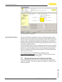
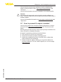
Fig.30:ExampleofaDTMview
Standard/Full version
All device DTMs are available as a free-of-charge standard version
and as a full version that must be purchased. In the standard version,
all functions for complete setup are already included. An assistant for
simpleprojectconfigurationsimplifiestheadjustmentconsiderably.
Saving/printing the project as well as import/export functions are also
part of the standard version.
In the full version there is also an extended print function for complete
project documentation as well as a save function for measured value
and echo curves. In addition, there is a tank calculation program as
well as a multiviewer for display and analysis of the saved measured
value and echo curves.
The standard version is available as a download under
www.vega.com/downloads and "Software". The full version is available on CD from the agency serving you.
7.3
Saving the parameter adjustment data
We recommend documenting or saving the parameter adjustment
data via PACTware. That way the data are available for multiple use or
service purposes.
36530-EN-140209
48
VEGAPULS 66 • Foundation Fieldbus
8 Set up with other systems
8
8.1
Set up with other systems
DD adjustment programs
Device descriptions as Enhanced Device Description (EDD) are
available for DD adjustment programs such as, for example, AMS™
and PDM.
Thefilescanbedownloadedatwww.vega.com/downloads under
"Software".
8.2
Field Communicator 375, 475
Device descriptions for the instrument are available as EDD for parameter adjustment with the Field Communicator 375 or 475.
36530-EN-140209
For the integration of the EDD in the Field Communicator 375 or 475,
the software "Easy Upgrade Utility" is required which is available from
the manufacturer. This software is updated via the Internet and new
EDDs are automatically taken over into the device catalogue of this
software after they are released by the manufacturer. They can then
be transferred to a Field Communicator.
VEGAPULS 66 • Foundation Fieldbus
49
9 Diagnosis, asset management and service
9
Diagnosis, asset management and service
9.1
Maintenance
9.2
Measured value and event memory
If the device is used correctly, no maintenance is required in normal
operation.
The instrument has several memories which are available for diagnosis purposes. The data remain even with voltage interruption.
Measured value memory
Up to 60,000 measured values can be stored in the sensor in a ring
memory. Each entry contains date/time as well as the respective
measured value. Storable values are for example:
•
•
•
•
•
•
•
•
Distance
Filling height
Percentage value
Lin. percent
Scaled
Current value
Meas. reliability
Electronics temperature
When the instrument is shipped, the measured value memory is
active and stores distance, measurement certainty and electronics
temperature every 3 minutes.
The requested values and recording conditions are set via a PC with
PACTware/DTM or the control system with EDD. Data are thus read
out and also reset.
Event memory
Up to 500 events are automatically stored with a time stamp in the
sensor (non-deletable). Each entry contains date/time, event type,
event description and value. Event types are for example:
•
•
•
•
Modificationofaparameter
Switch-onandswitch-offtimes
Status messages (according to NE 107)
Error messages (according to NE 107)
The data are read out via a PC with PACTware/DTM or the control
system with EDD.
Echo curve memory
The echo curves are stored with date and time and the corresponding
echo data. The memory is divided into two sections:
•
•
•
50
PC with PACTware/DTM
Control system with EDD
Display and adjustment module
VEGAPULS 66 • Foundation Fieldbus
36530-EN-140209
Echo curve of the setup: This is used as reference echo curve for
the measurement conditions during setup. Changes in the measurement conditions during operation or buildup on the sensor can thus
berecognized.Theechocurveofthesetupisstoredvia:
9 Diagnosis, asset management and service
Further echo curves: Up to 10 echo curves can be stored in a ring
bufferinthismemorysection.Furtherechocurvesarestoredvia:
•
•
PC with PACTware/DTM
Control system with EDD
9.3
Asset Management function
The instrument features self-monitoring and diagnostics according
to NE 107 and VDI/VDE 2650. In addition to the status messages in
the following tables there are more detailed error messages available
under the menu item "Diagnostics" via the display and adjustment
module, PACTware/DTM and EDD.
Status messages
The status messages are divided into the following categories:
•
•
•
•
Failure
Function check
Outofspecification
Maintenance requirement
and explained by pictographs:
1
2
3
4
Fig. 31: Pictographs of the status messages
1
2
3
4
Failure - red
Outofspecification-yellow
Function check - orange
Maintenance - blue
Failure: Due to a malfunction in the instrument, a failure message is
outputted.
This status message is always active. It cannot be deactivated by the
user.
Function check: The instrument is in operation, the measured value
is temporarily invalid (for example during simulation).
This status message is inactive by default. It can be activated by the
user via PACTware/DTM or EDD.
36530-EN-140209
Outofspecification: The measured value is unstable because the
instrumentspecificationisexceeded(e.g.electronicstemperature).
This status message is inactive by default. It can be activated by the
user via PACTware/DTM or EDD.
Maintenance:Duetoexternalinfluences,theinstrumentfunction
islimited.Themeasurementisaffected,butthemeasuredvalueis
still valid. Plan in maintenance for the instrument because a failure is
expected in the near future (e.g. due to buildup).
VEGAPULS 66 • Foundation Fieldbus
51
9 Diagnosis, asset management and service
This status message is inactive by default. It can be activated by the
user via PACTware/DTM or EDD.
Failure (failure)
The following table shows the codes and text messages of the status
message "Failure" and provides information on causes as well as
corrective measures.
Code
Cause
F013
– Sensor does not
– Check or correct
Bit 0
detect an echo during
installation and/or
operation
parameter adjustment
– Antenna system con- – Clean or exchange
taminated or defective
process component or
antenna
F017
– Adjustment not within
specification
F025
– Index markers are not – Checklinearization
continuously rising, for
table
example illogical value – Delete table/Create
pairs
new
Bit 2
F036
– Failed or interrupted
software update
– Repeat software
update
– Check electronics
version
– Exchanging the electronics
– Send instrument for
repair
Bit 3
F040
– Hardware defect
– Exchanging the electronics
– Send instrument for
repair
Bit 4
F080
– General software error – Disconnect operating
voltagebriefly
Bit 5
F105
– The instrument is still – Wait for the end of the Bit 6
in the start phase, the
switch-on phase
measured value could – Duration depending
not yet be determined
on the version and
parameter adjustment
up to approximately
3 min.
F113
– Error in the internal
instrument communication
Text message
no measured value
available
Adjustment
span too
small
Error in the
linearization table
No operable
software
Error in the
electronics
Determine
measured
value
52
PA DevSpec
Diagnosis
– Change adjustment
according to the limit
values(difference
between min. and
max.≥10mm)
– Disconnect operating
voltagebriefly
– Send instrument for
repair
Bit 1
Bit 7
VEGAPULS 66 • Foundation Fieldbus
36530-EN-140209
Communication error
Rectification
9 Diagnosis, asset management and service
Code
Cause
F125
– Temperature of the
– Check ambient temelectronics in the nonperature
specifiedsection
– Isolate electronics
– Use instrument with
higher temperature
range
Bit 8
F260
– Error in the calibration carried out in the
factory
– Error in the EEPROM
– Exchanging the electronics
– Send instrument for
repair
Bit 9
– Repeat setup
– Repeat reset
Bit 10
Text message
Impermissible
electronics
temperature
Error in the
calibration
– Error during setup
Error in the – False signal suppression faulty
configura– Error when carrying
tion
out a reset
F264
– Adjustment not within – Check or correct
Bit 11
the vessel height/
installation and/or
measuring range
parameter adjustment
– Max. measuring range – Use an instrument
of the instrument not
with bigger measuring
sufficient
range
F265
– Sensor no longer
– Check operating
carries out a measurevoltage
ment
– Carry out a reset
– Operating voltage
– Disconnect operating
too low
voltagebriefly
Installation/Setup
error
Measurement
function
disturbed
Bit 12
The following table shows the error codes and text messages in the
status message "Function check" and provides information on causes
as well as corrective measures.
Code
Cause
Rectification
C700
– A simulation is active
– Finish simulation
– Wait for the automatic end
after 60 mins.
Text message
Simulation active
The following table shows the error codes and text messages in the
status message "Outofspecification" and provides information on
causes as well as corrective measures.
36530-EN-140209
Outofspecification
PA DevSpec
Diagnosis
F261
Function check
Rectification
VEGAPULS 66 • Foundation Fieldbus
53
9 Diagnosis, asset management and service
Code
Cause
S600
Impermissible electronics
temperature
– Temperature of the elec– Check ambient temperature
tronicsinthenon-specified – Isolate electronics
section
– Use instrument with higher
temperature range
S601
– Dangerofvesseloverfilling
– Make sure that there is no
furtherfilling
– Check level in the vessel
S603
– Operating voltage below
specifiedrange
– Check electrical connection
– if necessary, increase
operating voltage
Text message
Overfilling
Impermissible operating
voltage
Maintenance
The following table shows the error codes and text messages in the
status message "Maintenance" and provides information on causes
as well as corrective measures.
Cause
Rectification
M500
– With the reset to delivery
status, the data could not
be restored
– Repeat reset
– LoadXMLfilewithsensor
data into the sensor
M501
– Hardware error EEPROM
– Exchanging the electronics
– Send instrument for repair
M502
– Hardware error EEPROM
– Exchanging the electronics
– Send instrument for repair
M503
Reliability too
low
– The echot/noise ratio is the
small for a reliable measurement
– Check installation and
process conditions
– Clean the antenna
– Change polarisation direction
– Use instrument with higher
sensitivity
M504
– Hardware defect
– Check connections
– Exchanging the electronics
– Send instrument for repair
Error with the
reset delivery
status
Error in the
non-active
linearization
table
Error in the
diagnosis
memory
Error on an
device interface
VEGAPULS 66 • Foundation Fieldbus
36530-EN-140209
Code
Text message
54
Rectification
9 Diagnosis, asset management and service
Code
Cause
Rectification
M505
– Level echo can no longer
be detected
– Clean the antenna
– Use a more suitable
antenna/sensor
– Remove possible false
echoes
– Optimizesensorposition
and orientation
Text message
No echo available
9.4
Rectify faults
Reaction when malfunctions occur
The operator of the system is responsible for taking suitable measures to rectify faults.
Procedure for fault rectification
Thefirstmeasuresare:
•
•
•
Evaluation of fault messages, for example via the display and
adjustment module
Checking the output signal
Treatment of measurement errors
Further comprehensive diagnostics options are available with a PC
with PACTware and the suitable DTM. In many cases, the reasons can
bedeterminedinthiswayandfaultsrectified.
Treatment of measurement errors with liquids
The below tables show typical examples of application-related measurementerrorswithliquids.Themeasurementerrorsaredifferentiated
according to the following:
•
•
•
Constant level
Filling
Emptying
Level
The images in column "Errorpattern" show the real level with a broken line and the level displayed by the sensor as a continuous line.
1
2
0
36530-EN-140209
1
2
time
Real level
Level displayed by the sensor
Notes:
• Wherever the sensor displays a constant value, the reason could
also be the fault setting of the current output to "Hold value"
• In case of a too low level indication, the reason could be a line
resistance that is too high
VEGAPULS 66 • Foundation Fieldbus
55
9 Diagnosis, asset management and service
Measurement error with constant level
1. Measured value
shows a too low or too
high level
Error pattern
Level
Fault description
0
Level
2. Measured value
jumps towards 0 %
time
0
Level
3. Measured value
jumps towards 100 %
time
0
time
Cause
Rectification
– Min./max. adjustment not
correct
– Adapt min./max. adjustment
– Wronglinearizationcurve
– Adaptlinearizationcurve
– Installation in a bypass tube or – Check parameter "Application"
standpipe, hence running time
with respect to vessel form,
error (small measurement error
adapt if necessary (bypass,
close to 100 %/large error close
standpipe, diameter)
to 0 %)
– Multiple echo (vessel top,
– Check parameter "Application",
product surface) with amplitude
especially vessel top, type
higher than the level echo
of medium, dished end, high
dielectric constant, adapt if
necessary
– Due to the process, the amplitude of the level echo sinks
– A false signal suppression was
not carried out
– Carry out a false signal suppression
– Amplitude or position of a
false echo has changed (e.g.
condensation, buildup); false
signal suppression no longer
matches
– Determine the reason for the
changed false signals, carry out
false signal suppression, e.g.
with condensation
Cause
Rectification
Measurementerrorduringfilling
4. Measured value remains unchanged
duringfilling
Error pattern
Level
Fault description
5. Measured value remains in the bottom
sectionduringfilling
0
– Echo from the tank bottom
larger than the level echo, for
example, with products with
εr < 2.5 oil-based, solvents
– Check parameters Medium,
Vessel height and Floor form,
adapt if necessary
– Turbulence on the product
surface,quickfilling
– Check parameters, change if
necessary, e.g. in dosing vessel, reactor
time
VEGAPULS 66 • Foundation Fieldbus
36530-EN-140209
56
time
Level
0
6. Measured value remains momentarily
unchangedduringfilling and then jumps to
the correct level
time
Level
0
– False echoes in the close range – Eliminate false echoes in the
close range
too big or level echo too small
– Check measurement situation:
– Strong foam or spout generaAntenna must protrude out of
tion
the socket, installations
– Max. adjustment not correct
– Remove contamination on the
antenna
– In case of interferences due to
installations in the close range:
Change polarisation direction
– Create a new false signal suppression
– Adapt max. adjustment
9 Diagnosis, asset management and service
7. Measured value
jumps towards 0 %
duringfilling
Error pattern
0
Cause
Rectification
– Amplitude of a multiple echo
– Check parameter "Application",
(vessel top - product surface) is
especially vessel top, type
larger than the level echo
of medium, dished end, high
dielectric constant, adapt if
necessary
Level
Fault description
time
– The level echo cannot be distin- – In case of interferences due to
guished from the false echo at
installations in the close range:
a false echo position (jumps to
Change polarisation direction
multiple echo)
– Chose a more suitable installation position
0
time
– Varying condensation or contamination on the antenna
Level
9. Measured value
jumps sporadically to
100%duringfilling
– Due to strong turbulence and
– Carry out a false signal supfoamgenerationduringfilling,
pression
the amplitude of the level echo
sinks. Measured value jumps to
the false echo
Level
8. Measured value
jumps towards 100 %
duringfilling
0
time
Level
10. Measured value
jumpsto≥100%or
0 m distance
0
time
– Carry out a false signal suppression or increase false
signal suppression with condensation/contamination in the
close range by editing
– Level echo is no longer
detected in the close range
– Check measuring site: Antenna
due to foam generation or false
must protrude out of the socket
echoes in the close range. The
– Remove contamination on the
sensorgoesintooverfillprotecantenna
tion mode. The max. level (0 m
–
Use a sensor with a more suitdistance) as well as the status
able antenna
message"Overfillprotection"
are outputted.
Measurement error during emptying
36530-EN-140209
12. Measured value
jumps towards 0 %
during emptying
Error pattern
Level
11. Measured value remains unchanged in
the close range during
emptying
0
time
Level
Fault description
0
time
Cause
Rectification
– False echo larger than the level – Remove false echoes in the
echo
close range. Check: Antenna
must protrude out of the socket
– Level echo too small
– Remove contamination on the
antenna
– In case of interferences due to
installations in the close range:
Change polarisation direction
– After removing the false echoes, the false signal suppression must be deleted. Carry out
a new false signal suppression
– Echo from the tank bottom
larger than the level echo, for
example, with products with
εr < 2.5 oil-based, solvents
VEGAPULS 66 • Foundation Fieldbus
– Check parameters Type of
medium, Vessel height and
Floor form, adapt if necessary
57
9 Diagnosis, asset management and service
13. Measured value
jumps sporadically towards 100 % during
emptying
Error pattern
Level
Fault description
0
Cause
Rectification
– Varying condensation or contamination on the antenna
– Carry out false signal suppression or increase false signal
suppression in the close range
by editing
– With bulk solids, use radar sensor with purging air connection
time
Reaction after fault rectification
Depending on the reason for the fault and the measures taken, the
steps described in chapter "Setup" must be carried out again or must
be checked for plausibility and completeness.
24 hour service hotline
Should these measures not be successful, please call in urgent cases
the VEGA service hotline under the phone no. +49 1805 858550.
The hotline is also available outside normal working hours, seven
days a week around the clock.
Sinceweofferthisserviceworldwide,thesupportisprovidedin
English. The service itself is free of charge, the only costs involved are
the normal call charges.
9.5
Exchanging the electronics module
If the electronics module is defective, it can be replaced by the user.
In Ex applications, only instruments and electronics modules with appropriate Ex approval may be used.
If there is no electronics module available on site, the electronics
module can be ordered through the agency serving you. The electronicsmodulesareadaptedtotherespectivesensoranddifferinsignal
output or voltage supply.
The new electronics module must be loaded with the default settings
of the sensor. These are the options:
•
•
In the factory
Or on site by the user
In both cases, the serial number of the sensor is needed. The serial
numbers are stated on the type label of the instrument, on the inside
of the housing as well as on the delivery note.
Whenloadingonsite,firstofalltheorderdatamustbedownloaded
from the Internet (see operating instructions manual "Electronics
module").
9.6
Software update
The following components are required to update the sensor software:
58
Sensor
Voltage supply
Interface adapter VEGACONNECT
PC with PACTware
Currentsensorsoftwareasfile
VEGAPULS 66 • Foundation Fieldbus
36530-EN-140209
•
•
•
•
•
9 Diagnosis, asset management and service
Youcanfindtheactualsensorsoftwareaswellasdetailedinformation of the procedure under "www.vega.com/downloads" and
"Software".
Youcanfindinformationabouttheinstallationinthedownloadfile.
Caution:
Instruments with approvals can be bound to certain software versions.Thereforemakesurethattheapprovalremainseffectivewitha
software update.
Youcanfinddetailedinformationonwww.vega.com/downloads and
"Approvals".
9.7
How to proceed if a repair is needed
Youcanfindarepairformaswellasdetailedinformationonhowto
proceed under www.vega.com/downloads and "Formsandcertificates".
By doing this you help us carry out the repair quickly and without having to call back for needed information.
If a repair is necessary, please proceed as follows:
•
•
•
36530-EN-140209
•
Printandfilloutoneformperinstrument
Clean the instrument and pack it damage-proof
Attach the completed form and, if need be, also a safety data
sheet outside on the packaging
Please contact the agency serving you to get the address for
thereturnshipment.Youcanfindtheagencyonourhomepage
www.vega.com.
VEGAPULS 66 • Foundation Fieldbus
59
10 Dismounting
10 Dismounting
10.1 Dismounting steps
Warning:
Before dismounting, be aware of dangerous process conditions such
as e.g. pressure in the vessel or pipeline, high temperatures, corrosive or toxic products etc.
Take note of chapters "Mounting" and "Connecting to power supply"
and carry out the listed steps in reverse order.
10.2 Disposal
The instrument consists of materials which can be recycled by specialised recycling companies. We use recyclable materials and have
designed the parts to be easily separable.
Correctdisposalavoidsnegativeeffectsonhumansandtheenvironment and ensures recycling of useful raw materials.
Materials: see chapter "Technicaldata"
If you have no way to dispose of the old instrument properly, please
contact us concerning return and disposal.
WEEE directive 2002/96/EG
This instrument is not subject to the WEEE directive 2002/96/EG and
the respective national laws. Pass the instrument directly on to a specialised recycling company and do not use the municipal collecting
points. These may be used only for privately used products according
to the WEEE directive.
36530-EN-140209
60
VEGAPULS 66 • Foundation Fieldbus
11 Supplement
11 Supplement
11.1 Technical data
General data
316L corresponds to 1.4404 or 1.4435
Materials, wetted parts
Ʋ Processfitting
Ʋ Process seal
Ʋ Antenna
Ʋ Antenna impedance cone
316L
On site
Enamel
PTFE
Ʋ seal, antenna system
PTFE
Ʋ Plastic housing
plastic PBT (Polyester)
Materials, non-wetted parts
Ʋ Aluminium die-casting housing
Ʋ Stainless steel housing
Ʋ Seal between housing and housing
cover
Ʋ Inspection window in housing cover
(optional)
Ʋ Ground terminal
Ohmic contact
Processfittings
Aluminium die-casting AlSi10Mg, powder-coated - basis:
Polyester
316L
NBR (stainless steel housing, precision casting), silicone
(aluminium/plastic housing; stainless steel housing,
electropolished)
Polycarbonate
316L
Betweengroundterminalandprocessfitting
Ʋ Flanges
DIN from DN 150
Ʋ Instrument (depending on housing,
processfittingandantenna)
approx. 27 … 41 kg (59.52 … 90.39 lbs)
Ʋ Plastic housing
max. 10 Nm (7.376 lbf ft)
Weights
Torque for NPT cable glands and Conduit tubes
Ʋ Aluminium/Stainless steel housing
The measured quantity is the distance between process
fittingofthesensorandproductsurface.Thereference
plane is the seal surface on the hexagon or the lower
sideoftheflange.
36530-EN-140209
Input variable
Measured variable
max. 50 Nm (36.88 lbf ft)
VEGAPULS 66 • Foundation Fieldbus
61
11 Supplement
1
3
2
4
Fig. 46: Data of the input variable
1
2
3
4
Reference plane
Measured variable, max. measuring range
Antenna length
Usefulmeasuringrange
Max. measuring range
Recommended measuring range
Output variable
Output
Ʋ Signal
Ʋ Physical layer
Damping (63 % of the input variable)
Channel Numbers
Ʋ Channel 1
Ʋ Channel 8
Ʋ Channel 9
Transmission rate
Ʋ Non-Ex and Ex ia instrument
Ʋ Ex-d instruments
Resolution, digital
62
up to 35 m (114.83 ft)
digital output signal, Foundation Fieldbus protocol
according to IEC 61158-2
0 … 999 s, adjustable
Process value
Electronics temperature
Count rate
31.25 Kbit/s
36530-EN-140209
Current value
35 m (114.83 ft)
10 mA, ±0.5 mA
16 mA, ±0.5 mA
> 1 mm (0.039 in)
VEGAPULS 66 • Foundation Fieldbus
11 Supplement
Accuracy (according to DIN EN 60770-1)
Process reference conditions according to DIN EN 61298-1
Ʋ Temperature
+18 … +30 °C (+64 … +86 °F)
Ʋ Relative humidity
45 … 75 %
Ʋ Air pressure
860 … 1060 mbar/86 … 106 kPa (12.5 … 15.4 psig)
Ʋ Min. distance to installations
> 200 mm (7.874 in)
Ʋ Falsereflections
Biggest false signal, 20 dB smaller than the useful signal
Installation reference conditions
Ʋ Reflector
Planeplatereflector
Deviation with liquids
See following diagrams
20 mm (0.788 in)
8 mm (0.315 in)
0
1,0 m (3.28 ft)
- 8 mm (- 0.315 in)
- 20 mm (- 0.788 in)
1
2
3
Fig. 47: Deviation under reference conditions
1
2
3
Reference plane
Antenna edge
Recommended measuring range
Repeatability
≤±1mm
Variablesinfluencingmeasurementaccuracy
Temperature drift - Digital output
±3 mm/10 K relating to the max. measuring range or
max. 10 mm
Additional deviation through electromag- < ±50 mm
netic interference acc. to EN 61326
36530-EN-140209
Influenceofthesuperimposedgasandpressuretotheaccuracy
The propagation speed of the radar impulses in gas or vapour above the medium is reduced by
highpressure.Thiseffectdependsonthesuperimposedgasorvapourandisespeciallylargeat
low temperatures.
Thefollowingtableshowstheresultingdeviationforsometypicalgasesandvapours.Thespecified
values refer to the distance. Positive values mean that the measured distance is too large, negative
values that the measured distance is too small.
VEGAPULS 66 • Foundation Fieldbus
63
11 Supplement
Gas phase
Air
Hydrogen
Steam (saturated steam)
Temperature
Pressure
1 bar
(14.5 psig)
10 bar
(145 psig)
50 bar
(725 psig)
100 bar
(1450 psig)
200 bar
(2900 psig)
0.00 %
0.22 %
1.2 %
2.4 %
4.9 %
200 °C/392 °F -0.01 %
0.13 %
0.74 %
1.5 %
3.0 %
400 °C/752 °F -0.02 %
0.08 %
0.52 %
1.1 %
2.1 %
20 °C/68 °F
-0.01 %
0.10 %
0.61 %
1.2 %
2.5 %
200 °C/392 °F -0.02 %
0.05 %
0.37 %
0.76 %
1.6 %
400 °C/752 °F -0.02 %
0.03 %
0.25 %
0.53 %
1.1 %
100 °C/212 °F 0.26 %
-
-
-
-
180 °C/356 °F 0.17 %
2.1 %
-
-
-
264 °C/507 °F 0.12 %
1.44 %
9.2 %
-
-
366 °C/691 °F 0.07 %
1.01 %
5.7 %
13.2 %
76 %
20 °C/68 °F
Characteristics and performance data
Measuring frequency
C-band(6GHztechnology)
Measuring cycle time approx.
Step response time1)
Beam angle2)
Ʋ Antenna ø 145 mm (DN 150)
350 ms
≤3s
20°
Ʋ Antenna ø 195 mm (DN 200)
17°
Ʋ Average spectral transmission power
density
-31dBm/MHzEIRP
Emitted HF power (depending on the parameter adjustment)3)
Ʋ Max. spectral transmission power
density
Ʋ Specificabsorptionrate(SAR)
+24dBm/50MHzEIRP
0.47 mW/kg
Ambient conditions
Ambient, storage and transport tempera- -40 … +80 °C (-40 … +176 °F)
ture
Process conditions
Fortheprocessconditions,pleasealsonotethespecificationsonthetypelabel.Thelowestvalue
always applies.
Fortheprocesstemperatureandthevesselpressure,youalsohavetonotethespecificationson
the type label! Always the lowest value is applicable!
-40 … +200 °C (-40 … +392 °F)
Time span after a sudden measuring distance change by max. 0.5 m in liquid applications until the output signal
has taken for the first time 90 % of the final value (IEC 61298-2).
Outsidethespecifiedbeamangle,theenergyoftheradarsignalhasalevelwhichisreducedby50%(-3dB)
3)
EIRP: Equivalent Isotropic Radiated Power
1)
2)
64
VEGAPULS 66 • Foundation Fieldbus
36530-EN-140209
Process temperature (measured on the
processfitting)
11 Supplement
Vessel pressure relating to the antenna
system
1 … 40 bar/-100 … 4000 kPa/-(-14.5 … 580.2 psig)
Vibration resistance
4gat5…200HzaccordingtoEN60068-2-6(vibration
with resonance)
Vesselpressurerelatingtotheflange
nominal stage
see supplementary instructions manual "Flanges accordingtoDIN-EN-ASME-JIS"
Electromechanical data - version IP 66/IP 67 and IP 66/IP 68; 0.2 bar
Options of the cable entry
Ʋ Cable gland
Ʋ Cable entry
Ʋ Blind plug
M20 x 1.5 (cable: ø 5 … 9 mm)
½ NPT
M20 x 1.5; ½ NPT
Ʋ Closing cap
M20 x 1.5; ½ NPT
Ʋ Signal circuit
Plug M12 x 1, according to ISO 4400, Harting HAN,
7/8" FF
Plug options
Ʋ Indication circuit
M12 x 1 plug
Wire cross-section (spring-loaded terminals)
Ʋ Massive wire, cord
Ʋ Stranded wire with end sleeve
0.2 … 2.5 mm² (AWG 24 … 14)
0.2 … 1.5 mm² (AWG 24 … 16)
Electromechanical data - version IP 66/IP 68 (1 bar)
Options of the cable entry
Ʋ Cable gland with integrated connection cable
Ʋ Cable entry
Ʋ Blind plug
Connection cable
Ʋ Wire cross-section
Ʋ Wire resistance
Ʋ Tensile strength
Ʋ Standard length
Ʋ Max. length
Ʋ Min. bending radius
Ʋ Diameter approx.
Ʋ Colour - Non-Ex version
36530-EN-140209
Ʋ Colour - Ex-version
Display and adjustment module
Display element
Measured value indication
Ʋ Number of digits
Ʋ Sizeofdigits
VEGAPULS 66 • Foundation Fieldbus
M20 x 1.5 (cable: ø 5 … 9 mm)
½ NPT
M20 x 1.5; ½ NPT
0.5 mm² (AWG 20)
<0.036Ω/m
< 1200 N (270 lbf)
5 m (16.4 ft)
180 m (590.6 ft)
25 mm (0.984 in) with 25 °C (77 °F)
8 mm (0.315 in)
Black
Blue
Display with backlight
5
W x H = 7 x 13 mm
65
11 Supplement
Adjustment elements
4 keys
Protection rating
Ʋ unassembled
Ʋ mounted into the housing without
cover
Materials
Ʋ Housing
IP 20
IP 40
ABS
Ʋ Inspection window
Polyester foil
Interface to the external display and adjustment unit
Data transmission
digital (I²C-Bus)
Configuration,connectioncable
4-wire, screened
Integrated clock
Date format
Day.Month.Year
TimezoneExfactory
CET
Cable length max.
Time format
25 m
12 h/24 h
Rate deviation max.
10.5 min/year
Measurement electronics temerature
Resolution
1 °C (1.8 °F)
Accuracy
±1 °C (1.8 °F)
Voltage supply
Operating voltage
Ʋ Non-Ex instrument
9 … 32 V DC
Ʋ Non-Ex instrument
Ʋ Ex-ia instrument - Power supply
FISCO model
Ʋ Ex-ia instrument - Power supply
ENTITY model
9 … 32 V DC
9 … 17.5 V DC
9 … 24 V DC
Ʋ Ex-d instrument
14 … 32 V DC
Ʋ Fieldbus
max. 32 (max. 10 with Ex)
Power supply by/max. number of sensors
Electrical protective measures
Protection rating
Version
IP-protection class
NEMA protection
Single chamber
IP 66/IP 67
NEMA4X
Double chamber
IP 66/IP 67
NEMA4X
66
VEGAPULS 66 • Foundation Fieldbus
36530-EN-140209
Housing material
Plastic
11 Supplement
Housing material
Version
IP-protection class
NEMA protection
Aluminium
Single chamber
IP 66/IP 68 (0.2 bar)
NEMA 6P
Double chamber
IP 66/IP 67
NEMA4X
IP 68 (1 bar)
NEMA 6P
IP 66/IP 68 (0.2 bar)
NEMA 6P
IP 68 (1 bar)
Stainless steel, electropolished
NEMA 6P
Single chamber
IP 66/IP 68 (0.2 bar)
NEMA 6P
Stainless steel, investment Single chamber
casting
IP 66/IP 68 (0.2 bar)
NEMA 6P
IP 66/IP 67
NEMA4X
IP 68 (1 bar)
NEMA 6P
IP 68 (1 bar)
Double chamber
Overvoltage category
NEMA 6P
IP 66/IP 68 (0.2 bar)
NEMA 6P
III
Protection class
III
Approvals
Instrumentswithapprovalscanhavedifferenttechnicaldatadependingontheversion.
For that reason the associated approval documents of these instruments have to be carefully
noted. They are part of the delivery or can be downloaded under www.vega.com, "VEGATools"
and "Instrument search" as well as via www.vega.com/downloads and "Approvals".
11.2 Supplementary information Foundation Fieldbus
The following table gives you an overview of the instrument versions and the corresponding device
descriptions, the electrical characteristics of the bus system as well as the applied function blocks.
DD-Revision
Rev_01
CFF-File
010101.cff
Device Revision
0101.ffo
Cff-Revision
xx xx 01
Device software revision
> 4.4.0
ITK (Interoperability Test Kit) Number
5.0.2
0101.sym
36530-EN-140209
Revisions Data
VEGAPULS 66 • Foundation Fieldbus
67
11 Supplement
Electricial Characteristics
Transmitter Function Blocks
Advanced Function Blocks
Diagnostics
General Information
Physicial Layer Type
Low-power signaling, bus-powered, FISCO I.S.
Input Impedance
> 3000 Ohms between
7.8KHz-39KHz
Unbalanced Capacitance
< 250 pF to ground from either
input terminal
Output Amplitude
0.8 V P-P
Electrical Connection
2 Wire
Polarity Insensitive
Yes
Max. Current Load
10 mA
Device minimum operating voltage
9V
Resource Block (RB)
1
Transducer Block (TB)
1
Standard Block (AI)
3
Execution Time
30 mS
Discret Input (DI)
Yes
PID Control
Yes
Output Splitter (OS)
Yes
SignalCharacterizer(SC)
Yes
Integrator
Yes
Input Selector (IS)
Yes
Arithmetic (AR)
Yes
Standard
Yes
Advanced
Yes
Performance
No
Function Blocks Instantiable
No
LAS (Link Active Scheduler)
Yes
Master Capable
Yes
Number of VCRs (Virtual Communication Relationships)
24
Function blocks
Transducer Block (TB)
The Transducer Block "Analog Input (AI)" takes the original measured value (Secondary Value 2),
carriesoutthemin./max.adjustment(SecondaryValue1),carriesoutalinearization(PrimaryValue)
and makes the values on its output available for further function blocks.
36530-EN-140209
68
VEGAPULS 66 • Foundation Fieldbus
11 Supplement
min/max
adjustment
Sensor_Value
Linearization
%
m(d)
Lin%
TB
Secondary
Value 2
Secondary
Value 1
Primary
Value
Fig.48:SchematicpresentationTransducerBlock(TB)
Function block Analog Input (AI)
The function block "Analog Input (AI)" takes the original measured value selected by a Channel
Number and makes it available to additional function blocks on its output.
Fig. 49: Schematic presentation function block Analog Input (AI)
Function block Discret Input (DI)
36530-EN-140209
The function block "Discret Input (DI)" takes the original measured value selected by a Channel
Number and makes it available to additional function blocks on its output.
Fig. 50: Schematic presentation function block Discret Input (DI)
VEGAPULS 66 • Foundation Fieldbus
69
11 Supplement
Function block PID Control
The function block "PID Control " is a key component for various tasks in the process automation
andisuseduniversally.PIDblockscanbecascadedifthisisnecessaryorrequestedduetodifferent time constants with the primary and secondary process measurement.
Fig. 51: Schematic presentation function block PID Control
Function block Output Splitter
The function block "Output Splitter" generates two control outputs out of one input. Each output is
a linear image of a part of the input. A retrograde calculation function is realised by using the linear
imaging function inversely. A cascading of several Output Splitters is supported by an integrated
decision table for the combinability of inputs and outputs.
36530-EN-140209
70
VEGAPULS 66 • Foundation Fieldbus
11 Supplement
Fig. 52: Schematic presentation function block Output Splitter
Function block Signal Characterizer
36530-EN-140209
The function block "Signal Characterizer" has two channels the outputs of which are not in linear
relationwiththerespectiveinput.Thenon-linearrelationisdefinedbyalook-uptablewithindividually selectable x/y-pairs. The respective input signal is imaged on the corresponding output, hence
this function block can be used in a control loop or signal path. Optionally the function axis can be
exchanged in channel 2 so that the block can be also used in a reverse control loop.
VEGAPULS 66 • Foundation Fieldbus
71
11 Supplement
Fig. 53: Schematic presentation function block Signal Characterizer
Function block Integrator
The function block "Integrator" integrates a continuous input signal over the time and sums the
resultsofanimpulseinputblock.Itisusedasatotalizeruptoaresetorasasubtotalizeruptoa
reference point at which the integrated and accumulated value is compared with the default values.
When these default values are reached, digital output signals will be outputted. The integration functioniscarriedoutupwardlystartingwithzeroanddownwardswithadefaultvalue.Twoflowvalues
arealsoavailablesothatthenetflowvolumecanbecalculatedandintegrated.Thiscanbeusedfor
calculationofvolumeandmasschangesinthevesselorforoptimisationofflowcontrols.
36530-EN-140209
72
VEGAPULS 66 • Foundation Fieldbus
11 Supplement
Fig. 54: Schematic presentation function block Integrator
Function block Input Selector
36530-EN-140209
The function block "Input Selector"offersselectionpossibilitiesforuptofourinputsandgenerates
an output signal according to the selection criteria. Typical input signals are AI blocks. Selection
possibilitiesaremaximum,minimum,meanvalue,averagevalueandfirstusefulsignal.Through
parameter combination, the block can be used as rotary switch or as preselection switch for the
firstusefulvalue.Switchinformationcanbereceivedbyotherinputblocksortheuser.Meanvalue
selection is also supported.
VEGAPULS 66 • Foundation Fieldbus
73
11 Supplement
Fig. 55: Schematic presentation function block Input Selector
Function block Arithmetic
The function block "Arithmetic" allows the simple integration of usual metrological calculation
functions. The user can select the requested algortihm according to the name without known the
formula.
The following algorithms are available:
•
•
•
•
•
•
•
•
•
•
Flow compensation, linear
Flow compensation, square root
Flow compensation, approximate
BTUflow
Traditional Multiply Divide
Average
Traditional Summer
Fourth order polynomial
Simple HTG compensated level
Fourth order Polynomial Based on PV
36530-EN-140209
74
VEGAPULS 66 • Foundation Fieldbus
11 Supplement
Fig. 56: Schematic presentation function block Arithmetic
Parameter list
36530-EN-140209
The following table gives you an overview of the parameters used.
FF desciptor
Description
PRIMARY_VALUE
PRIMARY_VALUE(Linearizedvalue).Thisistheprocessvalueaftermin/maxadjustmentandLinearizationwiththestatus
ofthetransducerblock.Theunitisdefinedin"PRIMARY_VALUE_UNIT"
PRIMARY_VALUE_UNIT
Selected unit code for "PRIMARY_VALUE"
SECONDARY_VALUE_1
This is the measured value after min/max adjustment with the
statusofthetransducerblock.Theunitisdefinedin"SECONDARY_VALUE_1_UNIT"
SECONDARY_VALUE_1_
UNIT
Selected unit code for "SECONDARY_VALUE_1"
SECONDARY_VALUE_2
This is the distance value ("sensor_value") with the status of the
transducerblock.Theunitisdefinedin"SECONDARY_VALUE_2_UNIT"
FILL_HEIGHT_VALUE
Fillingheight.Theunitisdefinedin"FILL_HEIGHT_VALUE_
UNIT"
FILL_HEIGHT_VALUE_UNIT
Filling height unit
CONST_VALUE
Constant value
SECONDARY_VALUE_1_
TYPE
Secondary value 1 type
SECONDARY_VALUE_2_
TYPE
Secondary value 2 type
FILL_HEIGHT_VALUE_Type
Filling height value type
DIAGNOSIS
AITB Diagnosis
Unit
DIAG_MASK_1
DIAG_OUT_1
VEGAPULS 66 • Foundation Fieldbus
75
11 Supplement
FF desciptor
Description
Unit
DIAG_MASK_2
DIAG_OUT_2
DEVICE_IDENTIFICATION
Manufacturer ID, device type, bus type ID, measurement principle, serial number, DTM ID, device revision
DEVICE_NAME
Device name
IS-SPARE_ELECTRONICS
Device name
DEVICE_VERSION_INFO
Hard- and software version for system, function and error
CALIBRATION_DATE
Day, month and year
FIRMWARE_VERSION_ASCII Software version
HW_VERSION_ASCII
Hardware version
ADJUSTMENT_DATA
Min./max.-adjustmentphysical,percentandoffset
FIRMWARE_VERSION_MAIN Firmware versions major, minor, revision and build
PHYSICAL_VALUES
Distance, distance unit, distance status, level and status
DEVICE_UNITS
Distance and temperature units of the instrument
APPLICATION_CONFIG
Medium type, media, application type, vessel bottom, vessel
height
LINEARIZATION_TYPE_SEL
Typeoflinearization
SIMULATION_PHYSCAL
INTEGRATION_DATA
Physicaloffsetandintegrationtime
DEVICE_CONFIG_PULS_
RADAR
Electronics variant, probe type, max. measuring range, antenna extension length, adjustment propagation antenna extension
lprapprovalconfiguration
ADJUSTMENT_LIMITS_MIN
Min.rangemin.-/max.-valuesphysical,percent,offset
ADJUSTMENT_LIMITS_MAX
Max.rangemin.-/max.-valuesphysical,percent,offset
FALSE_SIGNAL_COMMAND
%
%
FALSE_SIGNAL_CMD_CREATE_EXTEND
FALSE_SIGNAL_CMD_DELET_REGION
FALSE_SIGNAL_CMD_STATE Busy, last command, errorcode
FALSE_SIGNAL_CMD_CON- Amplitude safety of the 0 % curve, safety of the false signal supFIGURATION1
pression, position of the 0 % and 100 % curve in near and far
range
Gradient of the manual sectors, safety at the end of false echo
memory and depending on the import range gating out the false
signals
ECP_CURVE_AVARAGING_
CONFIG
Averaging factor on increasing and decreasing amplitude
LEVEL_ECHO_MEASUREMENT
Functionmeasuredvaluefilter
36530-EN-140209
FALSE_SIGNAL_CMD_CONFIGURATION2
ECHO_CURVE_STATUS
PACKET_COUNT
76
VEGAPULS 66 • Foundation Fieldbus
11 Supplement
FF desciptor
Description
Unit
GU_ID_END
ECHO_CURVE_READ
Echo curve data
ECHO_EVALUATOR
Echoparameters,firstlargeecho,amplitudethresholdfirst
large echo
ECHO_DECIDER
Echo selection criteria, fault signal on loss of echo, delay on
fault signal on loss of echo
DISPLAY_SETTINGS
Indication value, menu language, lightning
SIL_MODE
EDENVELOPE_CURVE_FILTER
Parametersofenvelopecurvefilter,activationofsmoothraw
value curve
EDDETECTION_CURVE_FIL- Parametersofthedetectionfilter,offsetthresholdvaluecurve
TER
EDECHO_COMBINATION
Parameters for echo combination, function combine echoes,
amplitudedifferenceofcombinedechoes,positiondifferenceof
combined echoes
LIN_TABLE_A … LIN_
TABLE_Q
32 couples of percentage and lin. percentage values
ELECTRONICS_INFORMATION
Electronics version
APPLICATION_CONFIG_
SERVICE
Limitation measuring range begin, safety of measuring range
end
LEVEL_ECHO_INFO
Level echo ID, amplitude, measurement safety
DEVICE_STATUS
Device status
FALSE_SIGNAL_LIMITS
False signal distance min./max.
USER_PEAK_ELEC_TEMP
Min.-/max.- values of electronics temperature, date
USER_MIN_MAX_PHYSICAL_VALUE
Min.-/max.- distance values, date
RESET_PEAK_PHYSICAL_
VALUE
36530-EN-140209
RESET_LINEARIZATION_
CURVE
DEVICE_STATUS_ASCII
Device status
ECHO_CURVE_PLICSCOM_
REQUEST
Parameters as curve selection and resolution
ECHO_CURVE_PLICSCOM_
LIMITS
Parameters as start and end
APPROVAL_WHG
Sensor acc. to WHG
DEVICE_STATE_CONFIG
Functioncheck,maintenancerequired,outofspecification
ELECTRONIC_TEMPERATURE
Electronics temperature
RESET_PEAK_ELECTRONIC_TEMP
FOCUS_RANGE_CONFIG
Width focusing range, time for opening the focusing range, min.
measurement reliability in and outside the focusing range
VEGAPULS 66 • Foundation Fieldbus
77
11 Supplement
FF desciptor
Description
NOISE_DETECTION_INFO
Increase of the system noise
Unit
NOISE_DETECTION_CONFIG
System noise treatment
ECHO_MEM_SAVE_CURVE_
TYPE
ECHO_MEM_STATE
Busy, curve type, error code
11.3 Dimensions
The following dimensional drawings represent only an extract of all possible versions. Detailed
dimensional drawings can be downloaded at www.vega.com/downloads under "Drawings".
Plastic housing
~ 69 mm
(2.72")
ø 79 mm
(3.11")
~ 84 mm
(3.31")
ø 79 mm
(3.11")
M20x1,5/
½ NPT
112 mm
(4.41")
112 mm
(4.41")
M16x1,5
M20x1,5/
½ NPT
1
2
Fig.57:HousingversionsinprotectionIP66/IP68(0.2bar)-withintegrateddisplayandadjustmentmodulethe
housingis9mm/0.35inhigher
1
2
Single chamber version
Double chamber version
Aluminium housing
~ 116 mm
(4.57")
~ 87 mm
(3.43")
ø 86 mm
(3.39")
ø 86 mm
(3.39")
120 mm
(4.72")
116 mm
(4.57")
M16x1,5
M20x1,5
M20x1,5/
½ NPT
M20x1,5/
½ NPT
2
Fig.58:HousingversionsinprotectionIP66/IP68(0.2bar)-withintegrateddisplayandadjustmentmodulethe
housingis9mm/0.35inhigher
1
2
78
Single chamber version
Double chamber version
VEGAPULS 66 • Foundation Fieldbus
36530-EN-140209
1
11 Supplement
Aluminium housing in protection rating IP 66/IP 68 (1 bar)
~ 105 mm
(4.13")
~ 150 mm
(5.91")
ø 86 mm
(3.39")
ø 86 mm
(3.39")
120 mm
(4.72")
116 mm
(4.57")
M16x1,5
M20x1,5
M20x1,5
M20x1,5/
½ NPT
1
2
Fig.59:HousingversionsinprotectionIP␣66/IP␣68(1␣bar)-withintegrateddisplayandadjustmentmodulethe
housingis9␣mm/0.35␣inhigher
1
2
Single chamber version
Double chamber version
Stainless steel housing
~ 87 mm
(3.43")
~ 69 mm
(2.72")
ø 79 mm
(3.11")
~ 59 mm
(2.32")
ø 80 mm
(3.15")
ø 86 mm
(3.39")
M20x1,5/
½ NPT
M20x1,5/
½ NPT
1
2
120 mm
(4.72")
112 mm
(4.41")
117 mm
(4.61")
M16x1,5
M20x1,5/
½ NPT
3
Fig.60:HousingversionsinprotectionIP66/IP68(0.2bar)-withintegrateddisplayandadjustmentmodulethe
housingis9mm/0.35inhigher
Single chamber version, electropolished
Single chamber version, precision casting
Double chamber version, precision casting
36530-EN-140209
1
2
3
VEGAPULS 66 • Foundation Fieldbus
79
11 Supplement
Stainless steel housing in protection rating IP 66/IP 68, 1 bar
~ 93 mm
(3.66")
~ 103 mm
(4.06")
ø 80 mm
(3.15")
~ 105 mm
(4.13")
ø 79 mm
(3.11")
ø 86 mm
(3.39")
M20x1,5/
½ NPT
120 mm
(4.72")
112 mm
(4.41")
117 mm
(4.61")
M16x1,5
M20x1,5
1
M20x1,5/
½ NPT
2
3
Fig.61:HousingversionsinprotectionIP␣66/IP␣68(1␣bar)-withintegrateddisplayandadjustmentmodulethe
housingis9␣mm/0.35␣inhigher
1
2
3
Single chamber version, electropolished
Single chamber version, precision casting
Double chamber version, precision casting
VEGAPULS 66, enamel
mm
D
b
k
D1
D2
d
DN 150 PN 16
DN 200 PN 16
285
22
240
212
144
162
12xø22
inch
D
b
k
D1
D2
d
340
0.87"
0.95"
295
9.45"
11.61"
268
8.35"
10.55"
5.67"
8x ø 0.87"
y
226
276
y
8.90"
6.38" 12x ø 0.87" 10.87"
80 mm
(3.15")
DN 150 PN 16 11.22"
DN 200 PN 16 13.39"
24
8xø22
y
b
d
D2
36530-EN-140209
D1
k
D
Fig.62:VEGAPULS66,enamel
80
VEGAPULS 66 • Foundation Fieldbus
11 Supplement
11.4 Industrial property rights
VEGA product lines are global protected by industrial property rights. Further information see
www.vega.com.
Only in U.S.A.: Further information see patent label at the sensor housing.
VEGA Produktfamilien sind weltweit geschützt durch gewerbliche Schutzrechte.
Nähere Informationen unter www.vega.com.
Les lignes de produits VEGA sont globalement protégées par des droits de propriété intellectuelle. Pour plus d'informations, on pourra se référer au site www.vega.com.
VEGA lineas de productos están protegidas por los derechos en el campo de la propiedad industrial. Para mayor información revise la pagina web www.vega.com.
Линии продукции фирмы ВЕГА защищаются по всему миру правами на интеллектуальную
собственность. Дальнейшую информацию смотрите на сайте www.vega.com.
VEGA系列产品在全球享有知识产权保护。
进一步信息请参见网站<www.vega.com>。
11.5 Trademark
36530-EN-140209
All the brands as well as trade and company names used are property of their lawful proprietor/
originator.
VEGAPULS 66 • Foundation Fieldbus
81
INDEX
INDEX
A
Adjustment 40, 41
Adjustment system 32
Agitator 16
Application
– Bulk solid 37
– Liquid 33
– Standpipe 33
C
Connecting
– Electrically 23
– Mechanically 13
– To the PC 47
Connection
– Steps 23
– Technology 23
Curve indication
– Echo curve 42
– False signal suppression 42
M
Main menu 32
Meas. reliability 41
Measured value memory 50
N
NAMUR NE 107 54
– Failure 52
P
Peak value indicator 41
R
Reflectionproperties33
Repair 59
Replacement parts
– Supplementary electronics Foundation
Fieldbus 11
S
D
Deviation 55
Service hotline 58
Socket 15
Status messages - NAMUR NE 107 51
E
T
Echo curve memory 50
Echo curve of the setup 42
EDD (Enhanced Device Description) 49
Error codes 53
Event memory 50
F
V
Vessel form 39
Vessel height 39
Vessel installations 16
Vessel insulation 21
36530-EN-140209
False signal suppression 42
Faultrectification55
FF parameter 75
Functional principle 10
Function blocks
– Analog Input (AI) 69
– Arithmetic 74
– Discret Input (AI) 69
– Input Selector 73
– Integrator 72
– Output Splitter 70
– PID Control 70
– SignalCharacterizer71
– Transducer Block (TB) 68
Type label 8
L
Linearisation curve 44
82
VEGAPULS 66 • Foundation Fieldbus
36530-EN-140209
Notes
VEGAPULS 66 • Foundation Fieldbus
83
All statements concerning scope of delivery, application, practical use and operating conditions of the sensors and processing systems correspond to the information
available at the time of printing.
Subject to change without prior notice
© VEGA Grieshaber KG, Schiltach/Germany 2014
VEGA Grieshaber KG
Am Hohenstein 113
77761 Schiltach
Germany
Phone +49 7836 50-0
Fax +49 7836 50-201
E-mail: [email protected]
www.vega.com
36530-EN-140209
Printing date: