1
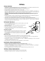
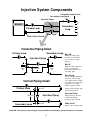
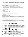
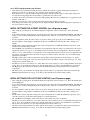
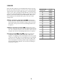
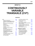
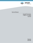
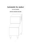
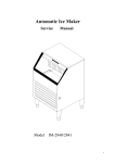
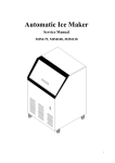
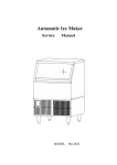
INSTALLATION/OPERATING INSTRUCTIONS VSP A Variable Speed Pump Control The VSP is a hydronic heating control. The temperature of the heating water is controlled by regulating the speed of a pump which injects water from a hot boiler loop (Primary loop) into a cooler heating loop (Secondary loop). As the speed of the pump increases, more hot water is sent into the Secondary loop, and the temperature of the heating water increases. The VSP can be used as an outdoor reset control. When the outdoor temperature falls below an adjustable start point, the heating system is activated. The temperature of the Secondary loop water is then automatically regulated based on outdoor temperature. The outdoor reset function maintains constant and comfortable ambient building temperatures in all weather conditions. The VSP can also be used as a set point control. In this mode of operation, the VSP will control the pump speed to hold a constant temperature (determined by the user) in the Secondary loop. The outdoor start temperature can be set to ON so the set point will be held regardless of outside temperature. The VSP is equipped with a Primary loop sensor. This sensor monitors the temperature of the boiler return water. If the boiler return water falls below an adjustable temperature, the VSP can be configured to slow down the speed of the injection pump to help the boiler return water temperatures recover. The VSP can be enabled or disabled from a standard thermostat or switch. Or, the VSP can reduce the temperature of the heating loop water when the building is not occupied or when occupants are sleeping. Table of Contents Piping..........................................................................................................................pg. 2 Piping Diagrams..................................................................................................................pg. 3 Pipe Sizing..................................................................................................................pg. 4 Control Installation..............................................................................................................pg. 7 Display Chart...................................................................................................................pg. 10 Operation.................................................................................................................pg. 11 Troubleshooting.................................................................................................................pg. 14 1 PIPING PIPING OVERVIEW • The Primary loop may have multiple injection loops or other takeoffs. However, the piping for each injection system must meet the requirements described below and shown on the next page. • The Injection piping can be installed in either a horizontal or a vertical configuration. • The pipe diameters of the Primary and Secondary loops may differ. • The Injection Piping diameter must be at least one pipe size smaller than the smaller of the Primary or Secondary loop piping. For example, if the Primary loop diameter is 1 1/4" and the Secondary loop diameter is 1", then the diameter of the Injection piping must be 3/4" or smaller. See Sizing pages 4 and 5 for actual pipe size. CAUTION: The Injection pump and pipe sizing should be performed by a qualified engineer or contractor. • The Injection pump motor must be a fractional horsepower permanent split capacitor type. The Injection pump will control the amount of water pumped from the hot Primary loop into the Secondary loop. • A globe type valve should be installed on the injection return piping. This helps to balance the system. • The distance between the injection tees should be as short as possible. The maximum distance between the two tees can be no more than 4 times the pipe diameter. For instance, if the pipe diameter is 1" then the length of straight pipe between the two injection tees can not exceed 4". INSTALLING THE WELLS • Two wells are supplied with the VSP. One is for the Secondary loop sensor and TEE one is for the Return water sensor. • The wells should not be located more than 500' from the VSP controller. SOLDER • Both wells are 3/8" ID. 3/4" WELL • The wells are designed to be installed in a tee with a 3/4" bull. HT# 350147 • Solder the well into the bull of the tee as shown. Slide the sensor into the well after the joint has cooled. Secondary Loop Well STOP • This well should be located past the pump in the Secondary loop supply. • The sensor in this well will measure the temperature of the Secondary loop. The VSP will control the Injection pump based on the information SENSOR HT#904015 from this sensor. Boiler Return Well • The sensor in this well will measure the temperature of the water returning to the boiler. • If the sensor is installed, it will allow the control to reduce the demand of the Secondary loop to help speed boiler recovery in the event of low boiler return temperatures (see Low Return pg. 13). • The VSP can be configured to control without this sensor input (see NOTE in Low Return pg. 13). It is not necessary to install this well if the input will not be used. • The well should be located in the boiler return of the Primary loop after all returns. HORIZONTAL PIPING CONFIGURATION • The Injection piping can be installed horizontally as shown on the next page. • The Injection supply piping should run horizontally from the Primary to the Secondary loop. • On the Injection return piping it is necessary to install a heat trap to prevent heat from the Primary loop entering the Secondary loop when the Injection pump is not running. • The return piping must drop down vertically at least 18" and then rise back up vertically at least 18". VERTICAL PIPING CONFIGURATION • The Injection piping can be installed vertically as shown on the next page. • The Primary loop must be at least 18" vertically above the Secondary loop. 2 Injection System Components Secondary Loop Sensor Secondary Loop Pum p Injection Pum p1 BOILER Secondary Loop Primary Loop Globe Valve 2 Boiler Return Sensor Horizontal Piping Detail Primary Loop Secondary Loop Max 4D Maximum length of pipe between tees should not exceed 4 times the pipe diameter Injection Piping 1 Min 18" 2 Max 4D Max 4D Min 18 " Minimum v ertical drop of 18 inches on heat trap or between the Primary and Secondary loops Pipe Sizing Vertical Piping Detail Max 4D Primary Loop Min 18" Secondary Loop 2 1 The Injection piping diameter must be at least one pipe size smaller than the smaller of the Primary or Secondary loop piping. See Sizing Charts on pages 4 and 5. Primary and Secondary pipe diameters may dif f er Injection Piping Max 4D Injection Pum p1 Pump motor ty pe must be f ractional horsepower permanent split capacitor Globe Valve 2 Balances the heating sy stem CAUTION: The Injection pump and pipe sizing should be performed by a qualified engineer or contractor. 3 INJECTION PIPE AND PUMP SIZING CHARTS To determine the proper Injection Piping Size and appropriate pump, it is necessary to know the following four items: Primary Loop Temperature - This is the temperature the Primary loop will maintain. Secondary Loop Temperature - This is the design temperature for the Secondary loop. If an outdoor reset function is being employed, this is the required temperature of the Secondary loop under maximum load. Delta T of the Secondary Loop - This is the design drop in temperature through the Secondary loop. In most radiant heat applications, the Delta T is 10. Other types of radiation, such as baseboard, have a higher design Delta T. Maximum Injection BTUs - This is the maximum heat requirement of the Secondary loop. The Maximum Injection BTUs is based on the Injection pump running at the highest speed. As the pump speed is reduced, fewer BTUS will be delivered to the system. EXAMPLE: Primary Loop Temperature Secondary Loop Temperature Delta T Secondary Loop Maximum BTUs Required 140°F 100°F 10°F 200,000 First calculate the Primary Loop Temperature minus the Secondary Loop Temperature: 140 - 100 = 40 The Delta T of the Secondary Loop is 10 Checking the first chart (Pipe Size 1/2", Globe Valve 20%) the intersection of the row marked 40 (Primary - Secondary loop temp) and the column marked 10 (Delta T) provides 50,000 as the maximum amount of BTUs. This is too low. Move on to the next chart. Checking the second chart (Pipe Size 1/2", Globe Valve 100%) the intersection of the two values provides 112,500 as the maximum amount of BTUs. This is too low. Move on to the next chart. Checking the third chart (Pipe Size 3/4", Globe Valve 100%) the intersection of the two values provides 212,500 as the maximum number of BTUs. This is just slightly more than the required Maximum BTU value. Use 3/4" Injection piping with any of the following pumps: Taco 007, Grundfos 15-42, B&G NRF22. Inj ection Piping Size 1/2" Globe Valv e Opening20% Primary Loop Temperature minus Secondary Loop Temperature 100 80 60 40 20 10 Inj ection Piping Size 1/2" Globe Valv e Opening100% Primary Loop Temperature minus Secondary Loop Temperature 100 80 60 40 20 10 10 Delta T of Secondary Loop 15 20 110,000 115,000 120,000 90,000 95,000 100,000 70,000 75,000 80,000 50,000 55,000 60,000 30,000 35,000 40,000 20,000 25,000 30,000 10 Maximum Injection BTUs Typical Pump Models: Taco 007 Grundfoss 15-42 B&G NRF22 Maximum Injection BTUs Typical Pump Models: Taco 007 Grundfoss 15-42 B&G NRF22 Delta T of Secondary Loop 15 20 247,500 202,500 258,750 213,750 270,000 225,000 157,500 168,750 180,000 112,500 123,750 135,000 67,500 78,750 90,000 45,000 56,250 67,500 4 Inj ection Piping Size 3/4" Globe Valv e Opening100% Primary Loop Temperature minus Secondary Loop Temperature 100 80 60 40 20 10 Inj ection Piping Size 1" Globe Valv e Opening100% Primary Loop Temperature minus Secondary Loop Temperature 100 80 60 40 20 10 Inj ection Piping Size 1 1/4" Globe Valv e Opening100% Primary Loop Temperature minus Secondary Loop Temperature 100 80 60 40 20 10 Inj ection Piping Size 1 1/2" Globe Valv e Opening100% Primary Loop Temperature minus Secondary Loop Temperature 100 80 60 40 20 10 Inj ection Piping Size 2" Globe Valv e Opening100% Primary Loop Temperature minus Secondary Loop Temperature 100 80 60 40 20 10 10 Delta T of Secondary Loop 15 20 467,500 488,750 510,000 382,500 403,750 425,000 297,500 318,750 340,000 212,500 233,750 255,000 127,500 148,750 170,000 85,000 106,250 127,500 10 715,000 747,500 780,000 617,500 487,500 650,000 520,000 325,000 357,500 390,000 195,000 227,500 260,000 130,000 162,500 195,000 1,207,500 1,260,000 945,000 997,500 1,050,000 735,000 787,500 840,000 525,000 577,500 630,000 315,000 367,500 420,000 210,000 262,500 315,000 Typical Pump Models: Taco 007 Grundfoss 15-42 B&G NRF22 Maximum Injection BTUs Typical Pump Models: Taco 0010 Grundfoss 26-64 Maximum Injection BTUs Typical Pump Models: Taco 0012 Grundfoss 43-75 Maximum Injection BTUs Typical Pump Models: Taco 0012 Grundfoss 43-75 Delta T of Secondary Loop 15 20 1,760,000 1,840,000 1,920,000 1,440,000 1,520,000 1,600,000 1,120,000 1,200,000 1,280,000 800,000 880,000 960,000 480,000 560,000 640,000 320,000 400,000 480,000 10 Maximum Injection BTUs Delta T of Secondary Loop 15 20 1,155,000 10 Typical Pump Models: Taco 007 Grundfoss 15-42 B&G NRF22 Delta T of Secondary Loop 15 20 585,000 455,000 10 Maximum Injection BTUs Delta T of Secondary Loop 15 20 2,310,000 1,890,000 2,415,000 1,995,000 2,520,000 2,100,000 1,470,000 1,575,000 1,680,000 1,050,000 1,155,000 1,260,000 630,000 735,000 840,000 420,000 525,000 630,000 CAUTION: Sizing Charts are based on Industry Standards. Values are approximations only. Actual piping arrangements may affect outputs. The correct pipe and pump sizes for any application should be performed by a qualified engineer or contractor. 5 VSP WIRING DIAGRAM Outdoor Sensor VSP 120VAC LINE NEU BLUE Wire Sensor Shields to either COM Screw RED BLACK Setback or Remote Enable 6 Pump Starter/ Motor** Pump Motor* BOILER Boiler Return Sensor Injection Pump Secondary Loop Pump Secondary Loop Sensor * Must be connected directly to 120VAC motor. NO PUMP STARTER. ** If Pump Starter/Motor is not rated for 120VAC power, contact the factory for wiring directions L O A D CONTROL INSTALLATION MOUNTING THE CONTROL • The VSP is designed to mount on a 1900 (4”x4”) electrical box. • If the VSP is to be panel mounted, or if additional room is needed for wiring, an extension kit is available (HT #908520). • Locate the VSP in a convenient location near the variable speed pump. The VSP can not be mounted more than 500' from any sensor location. • Mount the VSP away from excessive heat or cold. Ambient operating temperature is from 20 to 120°F. • After completing all the wiring connections (see opposite page) use the two screws provided to mount the VSP to the 1900 box. INSTALLING THE SENSORS • All three sensors are interchangeable. • The sensor wires can be extended up to 500' from the controller by splicing with shielded two conductor 18 gauge wire.. Do not connect the shield at the sensor end. Do not run wires in conduit with line voltage. • The Secondary loop sensor should be inserted in the well as described on pg. 2. • The Boiler return water sensor, if used, should be inserted in the well as described on pg. 2. • The Outdoor sensor should be mounted in the shade on the north side of the building (never in direct sunlight). Keep the sensor approximately 10' above ground level and away from doors, windows, exhaust fans, or other heat sources. WIRING THE SENSORS • The sensor wires have no polarity. Either wire from a sensor can be connected to the appropriately marked VSP screw terminal (see pg. 11) or the sensor common marked COM. • Either or both screw terminals marked COM can be used as the sensor common. They are interchangeable. • If the sensor wires have been extended, connect the shield to a COM terminal. • The two wires from the Secondary loop sensor must be connected to the VSP front screws marked SEC and COM. • The two wires from the Outdoor sensor must be connected to the VSP front screws marked OUT and COM. • The two wires from the Boiler return water sensor, if used, must be connected to the VSP front screws marked RTN and COM. (If not using this sensor, see the NOTE in Low Return pg. 13). WIRING THE VSP POWER • Attach 120VAC line voltage to the two Blue wires extending from the back of the VSP. • Use wire nuts, or wrap the connections with electrical tape. • Class 1 voltages must enter the 1900 box through a different opening from any Class 2 wiring. WIRING THE INJECTION PUMP • • • • The Red wires provide a solid state switching output to the Injection pump. The Injection pump motor must be a fractional horsepower permanent split capacitor type motor. The output is designed for AC power only. The maximum rating for the injection pump output is 3A 1/4HP. The Red wires must be directly in series with the pump power (see pg. 6). The signal can not be wired through any pilot duty relays or pump starters. • Safety limit switches or HOA switches must be wired in series with the pump power. • Use wire nuts, or wrap the connections with electrical tape. • Class 1 voltages must enter the 1900 box through a different opening from any Class 2 wiring. Warning: This Heat-Timer control is strictly an operating control; it should never be used as a primary limit or safety control. All equipment must have its own certified limit and safety controls required by local codes. The installer must verify proper operation and correct any safety problems prior to the installation of this Heat-Timer control. 7 WIRING THE SECONDARY LOOP PUMP • • • • • • The Black wires provide a Normally Open (N.O) relay output for the Secondary loop pump. The Black wires are a dry contact output only. They do not source any power. The Secondary loop pump relay is rated at 8A 1/8HP. Use wire nuts, or wrap the connections with electrical tape. Class 1 voltages must enter the 1900 box through a different opening from any Class 2 wiring. Wire the N.O. dry contacts to the pump starter. WIRING THE EXT INPUT • The EXT and COM terminals can only accept a dry contact input. If power is applied across these terminals, the VSP may be damaged. • The EXT Input can be configured to provide one of the following two functions: Setback Mode • The EXT Input can be used to accept an input from an external clock to lower the temperature of the Secondary loop when the building is not occupied, or when the occupants are sleeping. • When the EXT to COM terminals are open, the VSP will run normally. • When the EXT to COM terminals are shorted together the temperature of the Secondary loop will be reduced by the number of degrees of Setback (see pg. 13). Thermostat Mode • The EXT Input can be used to accept an input from a thermostat to activate the heating system. • When the EXT to COM terminals are open, the VSP will not be active. Both pump outputs will be disabled. • When the EXT to COM terminals are shorted together, the VSP will activate the heating system if there is a call for heat (based on System Start setting described on pg. 11). SETTING THE OPERATING MODES • Whenever the VSP is powered up, it will display the software version number and then the current operating modes. Each display will remain on the screen approximately 5 seconds. If the modes are correct, there is no need to make any adjustments. • Once the modes have been set for a particular application, they will be retained in memory and will not need to be reset. • Note that if you do change an operating mode, you will need to reset all other settings. • An operating mode can only be changed when it is being displayed in the start-up sequence. To restart the sequence it is necessary to remove power to the VSP and then power it again. • Set the operating modes as described in sequence below: °F or °C - Fahrenheit or Celsius Temperature Operation • If the display shows °F then the VSP will operate in Fahrenheit degrees. • If the display shows °C then the VSP will operate in Celsius degrees. • To change the mode, hold down the center button while pushing either the UP or DOWN button to toggle between the displays of °F and °C. • When the correct temperature mode is selected, release the buttons and wait approximately 5 seconds. rSt or SP - Reset or Set Point Operation • If the display shows rSt then the VSP will run with as an outdoor reset control (see pg. 12). As it gets colder outside, the VSP will automatically increase the temperature of the Secondary loop. • If the display shows SP then the VSP will hold the selected set point temperature in the Secondary loop. To select the Set Point, see chart pg. 10. • To change the mode, hold down the center button while pushing either the UP or DOWN button to toggle between the displays of rSt and SP. • When the correct mode is selected, release the buttons and wait approximately 5 seconds. Sb or thr - Setback or Thermostat Mode • If the display shows Sb then the VSP will use the EXT Input (see above) for an external clock or switch to lower the temperature of the Secondary loop. • If the display shows thr then the VSP will use the EXT Input for a thermostat. When the thermostat input is open, both pump outputs will be disabled. • To change the mode, hold down the center button while pushing either the UP or DOWN button to toggle between the displays of Sb and thr. • When the correct mode is selected, release the buttons and wait approximately 5 seconds. 8 no or YES - Pump Activation every 24 hours • If the display shows YES then the VSP will activate both the Secondary Loop pump and the Injection pump for 5 minutes every 24 hours. Certain local codes (generally only in Canada) require this. • If the display shows no then the VSP will only run the pumps when the system requires it. This setting will prevent hot water from being pumped into the Secondary loop when there is no call for heat. • To change the mode, hold down the center button while pushing either the UP or DOWN button to toggle between the displays of YES and no. • When the correct mode is selected, release the buttons and wait approximately 5 seconds. • If any changes were made to the operating modes, the display will flash. Then the VSP will display the temperature of the sensor in the Secondary loop. INITIAL SETTINGS FOR A RESET CONTROL (see rSt previous page) • After setting the operating mode, the VSP will display the temperature of the Secondary loop. This is the default display. • To see and/or adjust the other parameters, press then release the center button marked PRESS TO READ. The VSP will display a code to indicate which parameter will be displayed next. After two seconds, the value of the parameter will be shown. • For those parameters where the values can be set (shown on chart pg. 10), press the UP or DOWN button to change the value while it is being displayed. Holding down the UP or DOWN button will cause the value to change more quickly. • The System Start (StS) temperature setting is the outdoor temperature above which the VSP will not give heat. Start with the factory default setting of 60°F. • The reSet Ratio (rSt) determines how quickly the water temperature in the Secondary loop will increase as the outdoor temperature decreases (see pg. 12). Lower numbered curves result in lower water temperatures. The factory default curve is 7 or (1:1). This means for every degree the outdoor temperature falls (below the System Start temperature) the Secondary loop temperature will be increased one degree. For baseboard heat, start with 7. For most radiant tubing applications, start with 3. • The Offset (OFF) value is added or subtracted to the calculated water temperature for the Secondary loop. It effectively moves the starting point of the reset curves up and down by the number of degrees selected (see pg. 12). Start with the factory default setting of 0. • The LOw return (LOr) comes factory set to OFF. This is the correct setting if you are not using the Boiler return water sensor. If you do use the Boiler return sensor, then the setting must be set to the boiler manufacturer's specification. • The High Supply (Hi) value must be adjusted to the maximum temperature value specified for the Secondary loop components. • The Setback (Sb) value determines how many degrees the Secondary loop temperature will be decreased when the EXT Input in the Setback mode (see pg. 13) is shorted. Start with the factory default setting of 20°F. INITIAL SETTINGS FOR A SET POINT CONTROL (see SP previous page) • After setting the operating mode, the VSP will display the temperature of the Secondary loop. This is the default value for the VSP display. • To see and/or adjust the other parameters, press then release the center button marked PRESS TO READ. The VSP will display a code to indicate which parameter will be displayed next. After two seconds, the value of the parameter will be shown. • For those parameters where the values can be set (shown on chart pg. 10), press the UP or DOWN button to change the value while it is being displayed. Holding down the UP or DOWN button will cause the value to change more quickly. • The System Start (StS) temperature setting is the outdoor temperature above which the VSP will not give heat. Set to ON if the system set point should be held regardless of outside temperature. • The reSet Ratio (rSt) and Offset (OFF) values have no effect and do not need to be adjusted. • The LOw return (LOr)comes factory set to OFF. This is the correct setting if you are not using the Boiler return water sensor. If you do use the Boiler return sensor, then the setting must be set to the boiler manufacturer's specification. • The Set Point (SP) should be set to the desired temperature for the Secondary loop. • The Setback (Sb) value determines how many degrees the Secondary loop temperature will be decreased when the EXT Input in the Setback mode (see pg. 13) is shorted. Start with the factory default setting of 20°F. 9 DISPLAY VALUES and ADJUSTMENTS PRESS LEFT BUTTON Once T wice 3 times 4 times 5 times 6 times VSP DISPLAY Outdoor Temp 1 Return Temp 1 System Start Reset Ratio Offset Release center button to read v alue If v alue needs adj ustment, press the UP or DOWN button For large adj ustments hold either button dow n T his is the temperature of the outdoor sensor. If it does not read correctly, check theTroubleshootingguide. T his is the temperature of the water returning to the boiler. If this sensor is not installed it will display OPN. If the sensor is installed and does not read correctly, check theTroubleshootingguide. T his is the outdoor temperature below which the VSP will activate the Secondary loop pump and control the variable speed pump. If the ON setting is selected, the VSP will activate or control both pumps regardless of outdoor temperature. If the OFF setting is selected, the VSP will never activate either pump. Set Point Operation: No Effect Reset Operation: T he higher the curve number selected, the faster the temperature of the Secondary loop will be increased as outdoor temperature decreases (for Reset curves see pg. 12). Set Point Operation: No Effect Reset Operation: T he Offset will adjust the calculated Secondary loop temperature (determined by the outdoor temperature, Reset Ratio and Setback) by the amount displayed. No Return Water Sensor: Set to OFF With Return Water Sensor: Set to the boiler manufacturer's Low /Min Return specification for minimum boiler return temperature. 7 times Reset Operation ONLY: T his is the highest Secondary loop water temperature the VSP will maintain. IMPORT ANT : T he VSP is not a safety control. All appropriate Hi/Max Supply safety controls must be installed. 7 times Set Point Operation ONLY: T his is the Secondary loop water temperature the VSP will maintain. IMPORT ANT : T he VSP is not a safety control. All appropriate safety controls must be installed. 8 times 9 times Default2 Set Point Setback T his is the number of degrees the Secondary loop water temperature will be lowered if the VSP is put into Setback. Secondary Loop T his is the temperature reading of the Secondary loop sensor. If it does not read correctly, check the Troubleshootingguide. Temp1 1 These are sensor readings. They can not be adjusted. 2 The display of each setting will remain active for approximately 20 seconds after the last adjustment. Then the display will revert to the default reading . 10 OPERATION Digital display defaults to read secondary loop temperature Inj ection pump output RED BLACK VSP Output light indicates w hen system is activ e Push this button to display sensor v alues and control parameters BLUE O UT PUT = Air T emp = Return T emp UP PRESS T O READ = System Start DO W N = Reset Ratio Secondary loop pump output 120VAC pow er input Push these buttons to adj ust control parameters = O ffset = Min Return = Max/Set Point = Setback SEC O U T R TN C O M EXT C O M Dry contact input for either Setback or Remote Enable/Disable Secondary loop sensor Outdoor sensor Boiler return sensor Sensor common OUTPUT LIGHT The output light has the following three indications: Light Off The heating system is not active. Neither the Secondary loop pump nor the Injection pump output are active. Light On The heating source output is active. The Secondary loop pump relay is energized, and the speed of the Injection pump is being controlled. Flashing The Secondary loop pump relay is energized to circulate the water through the loop. The Injection pump output is not active. This would occur when there is a call for heat, but the temperature of the Secondary loop is satisfied so none of the hot water from the Primary loop is needed in the Secondary loop. SYSTEM START TEMPERATURE The System Start (StS) is the outdoor temperature below which the Secondary loop pump will be activated to circulate water through the loop and the Injection pump speed will be regulated to control the temperature of the Secondary loop water. When the outdoor temperature rises above this point, the Secondary Pump relay (BLACK wires) and the Injection pump output (RED wires) will be off. The System Start is adjustable from 30° F to 70° F. The System Start also has two special modes: OFF When the System Start is set to OFF, neither the Secondary loop pump nor the Injection pump will run. This can be used for testing or to disable heat to the particular loop. Do not use this feature to turn off pumps for maintenance. For this, use the safety disconnect. ON When the System Start is set to ON, the Secondary loop pump will run regardless of outdoor temperature. The Injection pump speed will be regulated to control the temperature of the Secondary loop water temperature. Follow the chart on pg. 10 to adjust the System Start. 11 RESET RATIO Reset Ratio Curves Set Point Operation: reSet ratio (rSt) has no effect. 1:2 12 11 220 1:1.5 10 9 8 1:1.25 210 Adjust the reSet ratio in cold weather. If the ambient space temperatures are too cold in cold weather, increase the curve number by one. If the space temperatures are too warm in cold weather, decrease the curve number by one. After making a change to the ratio, wait 24 hours to evaluate the impact of the change. See chart pg. 10 to adjust the reSet ratio 200 7 1:1 190 180 170 6 1.25:1 160 5 1.5:1 150 4 2:1 140 120 3 3:1 2 4:1 110 1 8:1 130 100 70 60 50 40 30 20 10 0 -10 -20 Outdoor Temperature (in °F) Ratios represent Outdoor:Water OFFSET The ratios begin at 100° Water Temperature. Reset Operation: The OFFset (OFF) allows you to adjust the starting points of the Reset Ratio curves (see side charts). When the OFFset is changed, that change is always directly added or subtracted to the calculated water temperature. For instance, if the calculated Secondary loop water temperature were 130°F and the OFFset were changed from 0° to 10° (an increase of 10°), then the calculated water temperature would immediately change to 140°F. -20° Offset The ratios begin at 80° Water Temperature. Adjust theOFFset in mild weather. If the ambient space temperatures are warm in mild weather, decrease the OFFset. If the space temperatures are cold in the mild weather, increase the OFFset. The rule of thumb for baseboard radiation is to change the OFFset by 4° for every degree you wish to change the space temperatures. For radiant heat applications, change the OFFset by 1° or 2° for every degree you wish to change the space temperature. See chart on 10 to adjust the OFFset. +20° Offset The ratios begin at 120° Water Temperature. 12 11 130 7 120 110 100 Water Temperature 0° Offset Water Temperature Offset Examples Set Point Operation: OFFset (OFF) has no effect. 2 70 60 50 40 Outdoor T emperature 11 110 7 100 90 80 Water Temperature The ratios are adjustable from 8:1 (Curve 1) for the least amount of heat to 1:4 (Curve 12) for the most amount of heat (see side chart). With most baseboard heating applications, a 1:1 (Curve 7) setting is a good place to start. Radiant heat applications usually require a lower curve. 1:4 1:3 Water Temperature (in °F) Reset Operation: The reSet ratio (rSt) determines how the Secondary loop water temperature will vary with outside temperature. With any ratio, the colder it is outside, the hotter the temperature of the Secondary loop. At a 1:1 reset ratio (Curve 7) a 1 degree drop in outdoor temperature will increase the Secondary loop temperature by 1 degree; at the 3:1 ratio (Curve 3) an outdoor temperature drop of 3 degrees will increase the Secondary loop temperature by 1 degree. 2 70 60 50 40 Outdoor T emperature 150 11 7 140 130 120 2 70 60 50 40 Outdoor T emperature LOW (MINIMUM) RETURN The LOw return (LOr) setting is designed to help speed recovery in the event of low boiler return water temperatures. The boiler manufacturer may require a minimum return water temperature to protect their boiler. Check with the boiler manufacturer for the specified temperature. If the VSP registers that the temperature of the water returning to the boiler is below the LOw return, the VSP will immediately halve the Injection pump speed and not allow the speed to increase again until the return temperature rises to the LOw return setting. This means that the VSP will decrease the load on the Primary loop, but will still provide some heat to the Secondary loop. NOTE: If a minimum return water temperature is not specified by the boiler manufacturer, or if the Secondary loop size is such that it will have little impact on the Primary loop temperature, the Boiler Return sensor (see pg. 2) may not be installed. In that case it is necessary to adjust the LOw return setting to OFF (see chart on pg. 10). Otherwise, set the LOw return to the boiler manufacturer's specification. HIGH (MAXIMUM) SUPPLY (Reset Operation ONLY) The High Supply (Hi) setting is the maximum Secondary loop temperature the VSP will maintain. In some applications, it may be necessary to limit the temperature of the water going out to the Secondary loop. This may be done for comfort or because the Secondary loop components or flooring may be damaged by high temperatures. The High Supply should never be set higher than the maximum value specified by either the Secondary loop component or the flooring manufacturer. Adjust the High Supply as shown on the chart pg. 10. SET POINT (Set Point Operation ONLY) The Set Point (SP) setting is the Secondary loop temperature the VSP will maintain whenever there is a call for heat. The Set Point should never be set higher than the maximum value specified by either the Secondary loop component or the flooring manufacturer. Adjust the Set Point as shown on the chart pg. 10. SETBACK The Setback (Sb) setting has no effect if the VSP is in Thermostat mode (see pg. 8). When the VSP is initialized to run in the Setback mode, the EXT Input can be connected to an external clock or switch (see pg. 11). When the EXT to COM terminals are shorted, the VSP will reduce the temperature of the Secondary loop by the number of degrees selected. For instance, if the calculated Secondary loop water temperature were 130°F and the Setback were set to 10°, then if the EXT Input were shorted, the calculated water temperature would immediately change to 120°F. A rule of thumb for adjusting the Setback with baseboard radiation is to decrease the water temperature 4° for each degree you wish to lower the ambient space temperatures. Therefore, if you wish the space temperatures to be 5° colder at night or when the building is not occupied, adjust the setback to 20°. With radiant heat, adjust the setback only 1 or 2 degrees for each degree you wish to lower the space temperature. Warning: The VSP is an operating control only. If excessive temperatures will cause system damage, separate limit controls must be installed. 13 TROUBLESHOOTING OPERATION No Display: Check the 120VAC power into the Blue input wires. If power is present, turn the power to the VSP off and then back on. Display shows or flashes OPn or SHt: Follow the procedure for SENSORS on next page. OUTPUT light is OFF when heat is required: Check the System Start setting (see pg. 11). If the outdoor temperature sensor reading is above the setting, the VSP will not give heat. Also check if the VSP is in the Thermostat mode (see pg. 8). In the thermostat mode, the VSP will never give heat if terminals EXT and COM are not shorted together. OUTPUT light is FLASHING when heat is required: The Output light flashes when the Secondary loop pump is running, but the Injection pump is off. This will occur when the VSP is satisfied with the temperature of the Secondary loop. See Insufficient Heat conditions below. OUTPUT light is FLASHING or ON but Secondary loop pump is not running: Turn off the power to the Secondary loop pump. The VSP power must remain connected. Then disconnect all wires attached to the VSP Black wires. Test for continuity across the Black wires. If the wires are continuous, the VSP is working properly. Check the Secondary loop pump and its power. OUTPUT light is ON but Injection pump is not running: If the Output light is on, the Injection pump should be running. However, if it is running at a very low speed, it may be hard to detect. It is possible to test the Injection pump output with a voltmeter which can read at least 120VAC. Warning: This test can only be performed with the Injection Pump power connected. The 120VAC power can cause severe personal injury. This test should only be performed by a qualified electrician or electrical contractor. Place the leads of the voltmeter across the power inputs of the Injection pump. At the highest speed, the AC Volt reading will be approximately 120VAC. As the speed is decreased, the reading will decrease down to approximately 10VAC. At the lower speeds, the reading may fluctuate by several Volts. This is considered to be normal. OUTPUT light is OFF or FLASHING but Injection pump is running: When the Output light is off or flashing, the Injection pump should not be running. Check the wiring to see if any other control, a HOA switch, or other switch input is causing the pump to run. Turn the power off to the VSP. If the Injection pump continues to run, the VSP is not the cause of the pump running. Insufficient Heat when the OUTPUT light is ON (Reset Operation): Check all the settings. If the Boiler Return sensor reading is below the LOw return setting the VSP will halve the speed of the Injection pump until the boiler return temperatures recover. The temperature of the Secondary loop will never exceed the High Supply setting for any prolonged period of time. Check the High Supply is not set too low. Check if the VSP is in Setback and therefore running lower water temperatures. If none of these conditions are causing insufficient heat, then adjust the reSet ratio or OFFset (see pg. 12). Insufficient Heat when the OUTPUT light is ON (Set Point Operation): Check all the settings. If the Boiler Return sensor reading is below the LOw return setting (see pg. 13) the VSP will halve the speed of the Injection pump until the boiler return temperatures recover. Check if the VSP is in Setback and therefore running lower water temperatures. If neither of these conditions are causing insufficient heat, then adjust the Set Point (see pg. 13). 14 SENSORS Each of the three VSP sensors are interchangeable and can be tested in the same way. If the Secondary loop sensor is open or shorted, the main display will show OPn or SHt. If either the Outdoor or the Boiler Return sensor is open or short, the display will first flash the code for the sensor (either Air or rEt) and then flash OPn or SHt. To test the sensor, remove the pair of sensor wires connected to the VSP terminals. Take a resistance reading across the detached wires going to the sensor. If the reading shows: Ω : Check the wires OPEN or a resistance greater than 100,000Ω going to the sensor. They may have been broken or become disconnected. If the wires are fine, check the resistance at the sensor itself. If the value is still open, the sensor has been damaged and needs to be replaced. Ω: Check the wires going to SHORT or a resistance less than 100Ω the sensor. They may have become shorted together in the run of the wire. If not, check the resistance at the sensor itself. If there still is no resistance, the sensor has been damaged and needs to be replaced. Ω: Find the temperature that Ω to 100,000Ω: Resistances from 200Ω corresponds to the resistance value on the chart. If the sensor appears to be outputting correctly, check that the wires were properly connected to the VSP. If they were, the VSP may have been damaged. If the sensor is not outputting correctly, take another reading at the sensor itself. If this is correct, the problem is in the wiring between the sensor and the VSP. Otherwise, the sensor has been damaged, and should be replaced. 15 TEMPERATURE (in d egrees F) 0 10 20 25 30 35 40 45 50 55 60 70 80 90 1 00 1 10 1 20 1 30 1 40 1 50 1 60 1 70 1 80 1 90 2 00 VALUE (in Ohms) 42 68 3 31 21 5 23 08 9 19 93 9 17 26 4 14 98 5 13 04 0 11 37 4 99 44 87 14 76 53 59 41 46 49 36 67 29 14 23 32 18 79 15 24 12 43 10 21 8 42 6 99 5 83 4 89 4 12 Heat-Timer Controls for the HVAC/R & Plumbing Industry Steam heating controls Hydronic heating controls Sequencing controls Radiant heat controls Digital set point controls Precision tempering valves VARIVALVE air vents 2, 3, and 4 way motorized valves Snow melt controls Heat-Timer Corporation 20 New Dutch Lane Fairfield, NJ 07004 Phone (973)575-4004 Fax (973)575-4052 http://www.heat-timer.com 16 HT #059220-00 REV A