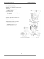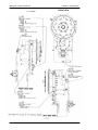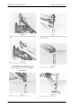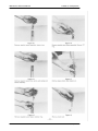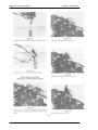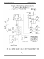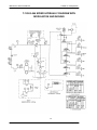
1
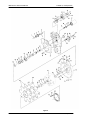
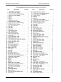
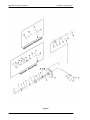
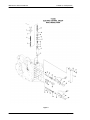
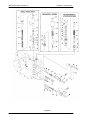
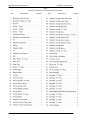
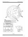
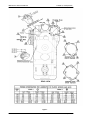
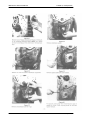
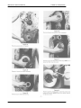
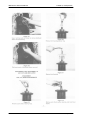
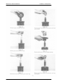
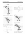
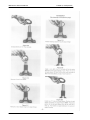
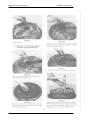
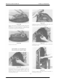
Service Manual
Powershift Transmission
T12000 3, 4, & 6-Speed
Long Drop
TSM-0023
April 2000
Maintenance & Service Manual
T12000 3,4 & 6 Speed LD
FOREWORD
This manual has been prepared to provide the customer and the maintenance personnel
with information and instructions on the maintenance and repair of the Spicer OffHighway Product.
Extreme care has been exercised in the design, selection of materials, and manufacturing
of these units. The slight outlay in personal attention and cost required to provide regular
and proper lubrication, inspection at stated intervals, and such adjustments as may be
indicated will be reimbursed many times in low cost operation and trouble free service.
In order to become familiar with the various parts of the product, its principle of operation,
troubleshooting, and adjustments, it is urged that the mechanic study the instructions in
this manual carefully and use it as a reference when performing maintenance and repair
operations.
Whenever repair or replacement of component parts is required, only Spicer Off-Highway
approved parts as listed in the applicable parts manual should be used. Use of "will-fit" or
non-approved parts may endanger proper operation and performance of the equipment.
Spicer Off-Highway does not warrant repair or replacement parts, nor failures resulting
from the use of parts which are not supplied by or approved by Spicer Off-Highway.
IMPORTANT: Always furnish the Distributor with the serial and model number
when ordering parts.
TOWING OR PUSH STARTING
Before towing the vehicle, be sure to lift the rear wheels off the ground or
disconnect the driveline to avoid damage to the transmission during towing.
NOTE : If the transmission has 4 wheel drive, disconnect both front and rear
drivelines. Because of the design of the hydraulic system, the engine cannot be
started by pushing or towing
©Copyright Dana Spicer Off-Highway Products Division
Unpublished Material – All rights reserved
Limited Distribution
No part of this work may be reproduced in any form
Under any means without direct written permission of
Dana Spicer Off-Highway Products Division
Date : Apr 2000
Maintenance & Service Manual
T12000 3,4 & 6 Speed LD
TABLE OF CONTENTS
T12000 TRANSMISSION ASSEMBLY
HOW THE UNITS OPERATE
SECTIONAL VIEWS AND PARTS IDENTIFICATION
Transmission Case and Plate Group.................................................................Fig. A
Converter Group................................................................................................ Fig. B
Forward -Reverse, 3rd and 4th -High Clutch Group. ......................................... Fig. C
Low (1st), 2nd and Output Shaft Group............................................................. Fig. D
Output Shaft Group with Disconnect. ................................................................ Fig. E
Control Valve Group-Dual Modulation.................................................................Fig. F
Control Valve Group-Single Modulation,
Mechanical Inching...................................................................................Fig. G
Assembly Instructions ....................................................................................Fig. H, I, J, K, L, M
DISASSEMBLY OF TRANSMISSION..............................................................................
REASSEMBLY OF TRANSMISSION.................................................................................... 58
CLUTCH ENGAGEMENT (POWER FLOW) 3 SPEED. ........................................................ 72
CLUTCH ENGAGEMENT (POWER FLOW) 4 AND 6 SPEED. ............................................ 73
DRIVEPLATEINSTALLATION .............................................................................................. 74
TRANSMISSION TO ENGINE INSTALLATION PROCEDURE. ........................................... 75
SPECIFICATIONSANDSERVICEDATA ............................................................................... 76
SERVICING MACHINE AFTER TRANSMISSION OVERHAUL. .......................................... 77
EXTERNAL PLUMBING AND PRESSURE CHECK POINTS............................................. 78, 79
CLEANINGANDINSPECTION .............................................................................................. 80
PARKINGBRAKESERVICE................................................................................................ 81
TROUBLESHOOTINGGUIDE............................................................................................. 82
CONVERTERSTALLPROCEDURE.................................................................................... 83
ELECTRIC SOLENOID CONTROL WIRING DIAGRAM..................................................... 84, 85
NOTE: Metric Dimensions Shown in Brackets [ ].
Date : Apr 2000
Maintenance & Service Manual
T12000 3,4 & 6 Speed LD
T12000
TRANSMISSION ASSEMBLY
The transmission and hydraulic torque converter portion of the power train enacts an important role in transmitting engine
power to the driving wheels. In order to properly maintain and service these units it is important to first understand their function
and how they operate.
The transmission and torque converter function together and operate through a common hydraulic system. It is necessary
to consider both units in the study of their function and operation.
The electric shift control valve is located in the vehicle's operator compartment, The function of the control is to energize
the selected solenoid valves thus directing the oil under pressure to the selected directional and range (gear) clutches. The
purpose of the range or directional clutches is to direct the power flow through the gear train to provide the desired speed
range and direction.
An axle disconnect is optional and is located on the output shaft. The drive to the front axle can be disconnected or
connected by manual, pneumatic, or hydraulic shifting.
When either directional clutch is selected the opposite clutch is relieved of pressure and vents back through the direction
selector solenoid to the oil sump. The same procedure is used in the speed selector.
The direction or speed clutch assembly consists of a drum with slots and a bore to receive a hydraulically actuated piston.
The piston is "oil tight" by the use of sealing rings. A steel disc with external tangs is inserted into the drum and rests against
the piston. Next, a friction disc with splines at the inner diameter is inserted, Discs are alternated until the required total is
achieved. A heavy back-up plate is then inserted and secured with a snap ring. A hub with O.D. splines is inserted into the
splines of discs with teeth on the inner diameter. The discs and hub are free to increase in speed or rotate in the opposite
direction as long as no pressure is present in that specific clutch.
To engage the clutch, the electric shift control lever is placed in the desired position. This energizes the selected direction
and range (gear) solenoids allowing the oil under pressure to flow through tubes and passages to the selected clutch shafts. Oil
sealing rings are located on the clutch shaft. These rings direct oil under pressure through a drilled passageway in the shaft to
a desired clutch. Pressure of the oil forces the piston and discs against the heavy back-up plate. The discs with tangs on the
outer diameter clamping against discs with teeth on the inner diameter enables the hub and clutch shaft to be locked together
and allows them to drive as a unit.
There are bleed balls in the clutch piston or clutch drum which allow quick escape for oil when the pressure to the piston
is released.
Date : Apr 2000
Maintenance & Service Manual
T12000 3,4 & 6 Speed LD
HOW THE UNITS OPERATE
With the engine running, the transmission charging pump draws oil from the transmission sump through the oil suction tube and screen
and directs it through the pressure regulating valve and oil filter.
The pressure regulating valve maintains pressure to the transmission solenoid valves for actuating the direction and speed clutches. This
regulator valve consists of a hardened valve spool operating in a closely fitted bore. The valve spool is spring loaded to hold the valve in the
closed position. When a specific pressure is achieved, the valve spool works against the spring until an exhaust port is exposed along the side
of the bore. This sequence of events provides the proper system pressure. This requires a small portion of the total volume of oil used in the
system.
The remaining volume of oil is directed out through an external oil cooler and into the lube inlet port. From the lube inlet port oil goes
through the forward-reverse shaft, lubricating the forward and reverse clutches, with the remainder going to the torque converter. After entering
the converter, the oil is directed through the converter blade cavity and exits in the passage between the turbine shaft and impeller hub. The oil
then lubes the impeller hub bearing with the remainder going to the 3rd-4th clutch shaft and 1st-2nd clutch shaft to lubricate those clutches and
shaft bearings. The oil then gravity drains to the transmission sump.
The hydraulic torque converter consists basically of three elements and their related parts to multiply engine torque. The engine power is
transmitted from the engine flywheel to the impeller element through the impeller cover. This element is the pump portion of the hydraulic
torque converter and is the primary component which starts the oil flowing to the other components which results in torque multiplication. This
element can be compared to a centrifugal pump in that it picks up fluid at its center and discharges at its outer diameter.
The torque converter turbine is mounted opposite the impeller and is connected to the output shaft of the torque converter. This element
receives fluid at its outer diameter and discharges at its center. Fluid directed by the impeller out into the particular design of blading in the
turbine and reaction member is the means by which the hydraulic torque converter multiplies torque.
The reaction member of the torque converter is located between and at the center of the inner diameters of the impeller and turbine
elements. Its function is to take the fluid which is exhausting from the inner portion of the turbine and change its direction to allow correct entry
for recirculation into the impeller element.
The torque converter will multiply engine torque to its designed maximum multiplication ratio when the output shaft is at zero R.P.M.
Therefore, we can say that as the output shaft is decreasing in speed the torque multiplication is increasing.
With the engine running and the electric shift control lever in neutral position, oil pressure from the regulating valve is blocked at the
solenoid control valves, and the transmission is in neutral. Movement of the control lever will energize the forward or reverse solenoid valves
and selected range (gear) solenoid, directing oil under pressure to the selected direction and range (gear) clutches.
Date : Apr 2000
Maintenance & Service Manual
T12000 3,4 & 6 Speed LD
Figure A
Date : Apr 2000
Maintenance & Service Manual
T12000 3,4 & 6 Speed LD
T12000
TRANSMISSION CASE AND PLATE GROUP
ITEM
DESCRIPTION
QUANTITY
ITEM
DESCRIPTION
AR -As Required
Date : Apr 2000
QUANTITY
Maintenance & Service Manual
T12000 3,4 & 6 Speed LD
Figure B
Date : Apr 2000
Maintenance & Service Manual
T12000 3,4 & 6 Speed LD
T12000 CONVERTER GROUP
Date : Apr 2000
Maintenance & Service Manual
T12000 3,4 & 6 Speed LD
Figure C
Date : Apr 2000
Maintenance & Service Manual
T12000 3,4 & 6 Speed LD
T12000 FORWARD-REVERSE, 3RD AND 4TH-HIGH CLUTCH GROUP
ITEM
DESCRIPTION
QUANTITY
ITEM
DESCRIPTION
Date : Apr 2000
QUANTITY
Maintenance & Service Manual
T12000 3,4 & 6 Speed LD
Figure D
Date : Apr 2000
Maintenance & Service Manual
T12000 3,4 & 6 Speed LD
T12000 LOW (1ST), 2ND, AND OUTPUT SHAFT GROUP
(WITH BRAKES)
ITEM
DESCRIPTION
QUANTITY
ITEM
DESCRIPTION
Date : Apr 2000
QUANTITY
Maintenance & Service Manual
T12000 3,4 & 6 Speed LD
Figure E
Date : Apr 2000
Maintenance & Service Manual
T12000 3,4 & 6 Speed LD
T12000 OUTPUT SHAFT GROUP (WITH HYDRAULIC OR
MECHANICAL DISCONNECT)
ITEM
DESCRIPTION
QUANTITY
ITEM
DESCRIPTION
Date : Apr 2000
QUANTITY
Maintenance & Service Manual
T12000 3,4 & 6 Speed LD
Figure F
Date : Apr 2000
Maintenance & Service Manual
T12000 3,4 & 6 Speed LD
T12000 CONTROL VALVE
GROUP DUAL MODULATION
ITEM
DESCRIPTION
QUANTITY
ITEM
DESCRIPTION
Date : Apr 2000
QUANTITY
Maintenance & Service Manual
T12000 3,4 & 6 Speed LD
Figure G
Date : Apr 2000
Maintenance & Service Manual
T12000 3,4 & 6 Speed LD
T12000
CONTROL VALVE GROUP WITH SINGLE MODULATION, INCHING
ITEM
DESCRIPTION
QUANTITY
ITEM
DESCRIPTION
Date : Apr 2000
QUANTITY
Maintenance & Service Manual
T12000 3,4 & 6 Speed LD
3 SPEED
ASSEMBLY INSTRUCTIONS
Figure H
Date : Apr 2000
Maintenance & Service Manual
T12000 3,4 & 6 Speed LD
4-6SPEED ASSEMBL Y INSTRUCTIONS
Figure I
Date : Apr 2000
Maintenance & Service Manual
T12000 3,4 & 6 Speed LD
Figure J
Date : Apr 2000
Maintenance & Service Manual
T12000 3,4 & 6 Speed LD
Figure K
Date : Apr 2000
Maintenance & Service Manual
T12000 3,4 & 6 Speed LD
Figure L
Date : Apr 2000
Maintenance & Service Manual
T12000 3,4 & 6 Speed LD
Figure M
Date : Apr 2000
Maintenance & Service Manual
T12000 3,4 & 6 Speed LD
Date : Apr 2000
Maintenance & Service Manual
T12000 3,4 & 6 Speed LD
Date : Apr 2000
Maintenance & Service Manual
T12000 3,4 & 6 Speed LD
Date : Apr 2000
Maintenance & Service Manual
T12000 3,4 & 6 Speed LD
Date : Apr 2000
Maintenance & Service Manual
T12000 3,4 & 6 Speed LD
Date : Apr 2000
Maintenance & Service Manual
T12000 3,4 & 6 Speed LD
Date : Apr 2000
Maintenance & Service Manual
T12000 3,4 & 6 Speed LD
Date : Apr 2000
Maintenance & Service Manual
T12000 3,4 & 6 Speed LD
Date : Apr 2000
Maintenance & Service Manual
T12000 3,4 & 6 Speed LD
Date : Apr 2000
Maintenance & Service Manual
T12000 3,4 & 6 Speed LD
Date : Apr 2000
Maintenance & Service Manual
T12000 3,4 & 6 Speed LD
Date : Apr 2000
Maintenance & Service Manual
T12000 3,4 & 6 Speed LD
Date : Apr 2000
Maintenance & Service Manual
T12000 3,4 & 6 Speed LD
Date : Apr 2000
Maintenance & Service Manual
T12000 3,4 & 6 Speed LD
Date : Apr 2000
Maintenance & Service Manual
T12000 3,4 & 6 Speed LD
Date : Apr 2000
Maintenance & Service Manual
T12000 3,4 & 6 Speed LD
Date : Apr 2000
Maintenance & Service Manual
T12000 3,4 & 6 Speed LD
Date : Apr 2000
Maintenance & Service Manual
T12000 3,4 & 6 Speed LD
Date : Apr 2000
Maintenance & Service Manual
T12000 3,4 & 6 Speed LD
Date : Apr 2000
Maintenance & Service Manual
T12000 3,4 & 6 Speed LD
Date : Apr 2000
Maintenance & Service Manual
T12000 3,4 & 6 Speed LD
Date : Apr 2000
Maintenance & Service Manual
T12000 3,4 & 6 Speed LD
Date : Apr 2000
Maintenance & Service Manual
T12000 3,4 & 6 Speed LD
Date : Apr 2000
Maintenance & Service Manual
T12000 3,4 & 6 Speed LD
Date : Apr 2000
Maintenance & Service Manual
T12000 3,4 & 6 Speed LD
Date : Apr 2000
Maintenance & Service Manual
T12000 3,4 & 6 Speed LD
Date : Apr 2000
Maintenance & Service Manual
T12000 3,4 & 6 Speed LD
Date : Apr 2000
Maintenance & Service Manual
T12000 3,4 & 6 Speed LD
Date : Apr 2000
Maintenance & Service Manual
T12000 3,4 & 6 Speed LD
Date : Apr 2000
Maintenance & Service Manual
T12000 3,4 & 6 Speed LD
Date : Apr 2000
Maintenance & Service Manual
T12000 3,4 & 6 Speed LD
Date : Apr 2000
Maintenance & Service Manual
T12000 3,4 & 6 Speed LD
Date : Apr 2000
Maintenance & Service Manual
T12000 3,4 & 6 Speed LD
Date : Apr 2000
Maintenance & Service Manual
T12000 3,4 & 6 Speed LD
Date : Apr 2000
Maintenance & Service Manual
T12000 3,4 & 6 Speed LD
Date : Apr 2000
Maintenance & Service Manual
T12000 3,4 & 6 Speed LD
Date : Apr 2000
Maintenance & Service Manual
T12000 3,4 & 6 Speed LD
Date : Apr 2000
Maintenance & Service Manual
T12000 3,4 & 6 Speed LD
Date : Apr 2000
Maintenance & Service Manual
T12000 3,4 & 6 Speed LD
Date : Apr 2000
Maintenance & Service Manual
T12000 3,4 & 6 Speed LD
Date : Apr 2000
Maintenance & Service Manual
T12000 3,4 & 6 Speed LD
Date : Apr 2000
Maintenance & Service Manual
T12000 3,4 & 6 Speed LD
Date : Apr 2000
Maintenance & Service Manual
T12000 3,4 & 6 Speed LD
Date : Apr 2000
Maintenance & Service Manual
T12000 3,4 & 6 Speed LD
Date : Apr 2000
Maintenance & Service Manual
T12000 3,4 & 6 Speed LD
Date : Apr 2000
Maintenance & Service Manual
T12000 3,4 & 6 Speed LD
Date : Apr 2000
Maintenance & Service Manual
T12000 3,4 & 6 Speed LD
Date : Apr 2000
Maintenance & Service Manual
T12000 3,4 & 6 Speed LD
Date : Apr 2000
Maintenance & Service Manual
T12000 3,4 & 6 Speed LD
Date : Apr 2000
Maintenance & Service Manual
T12000 3,4 & 6 Speed LD
Date : Apr 2000
Maintenance & Service Manual
T12000 3,4 & 6 Speed LD
Date : Apr 2000
Maintenance & Service Manual
T12000 3,4 & 6 Speed LD
Date : Apr 2000
Maintenance & Service Manual
T12000 3,4 & 6 Speed LD
Date : Apr 2000
Maintenance & Service Manual
T12000 3,4 & 6 Speed LD
Date : Apr 2000
Maintenance & Service Manual
T12000 3,4 & 6 Speed LD
Date : Apr 2000
Maintenance & Service Manual
T12000 3,4 & 6 Speed LD
Date : Apr 2000
Maintenance & Service Manual
T12000 3,4 & 6 Speed LD
Date : Apr 2000
Maintenance & Service Manual
T12000 3,4 & 6 Speed LD
Date : Apr 2000
Maintenance & Service Manual
T12000 3,4 & 6 Speed LD
Date : Apr 2000
Maintenance & Service Manual
T12000 3,4 & 6 Speed LD
Date : Apr 2000
Maintenance & Service Manual
T12000 3,4 & 6 Speed LD
Date : Apr 2000
Maintenance & Service Manual
T12000 3,4 & 6 Speed LD
Date : Apr 2000
Maintenance & Service Manual
T12000 3,4 & 6 Speed LD
Date : Apr 2000
Maintenance & Service Manual
T12000 3,4 & 6 Speed LD
Date : Apr 2000
Maintenance & Service Manual
T12000 3,4 & 6 Speed LD
Date : Apr 2000
Maintenance & Service Manual
T12000 3,4 & 6 Speed LD
Date : Apr 2000
Maintenance & Service Manual
T12000 3,4 & 6 Speed LD
Date : Apr 2000
Maintenance & Service Manual
T12000 3,4 & 6 Speed LD
Date : Apr 2000
Maintenance & Service Manual
T12000 3,4 & 6 Speed LD
Date : Apr 2000
Maintenance & Service Manual
T12000 3,4 & 6 Speed LD
Date : Apr 2000
Maintenance & Service Manual
T12000 3,4 & 6 Speed LD
Note: The disc spring packs are to be used as complete
assemblies and care should be taken not to intermix the
individual disc springs with disc springs in another clutch
or disc spring pack. Service replacement assemblies are
banded together and must be replaced as assembly.
Date : Apr 2000
Maintenance & Service Manual
T12000 3,4 & 6 Speed LD
CLUTCH ENGAGEMENT
-72
Date : Apr 2000
Maintenance & Service Manual
T12000 3,4 & 6 Speed LD
CLUTCH ENGAGEMENT
-73
Date : Apr 2000
Maintenance & Service Manual
T12000 3,4 & 6 Speed LD
DRIVE PLATE INSTALLATION
Measure the '"A" dimension (Bolt Circle diameter) and order Drive Plate Kit listed below.
Note two (2) kits have two (2) intermediate drive plates and one (1) drive plate and weld nut assembly. Two (2) kits
with three intermediate drive plates.
" A " Dimension (Bolt Circle Diameter)
"" A " Dimension (Bolt Circle Diameter)
11.380" 1288,900 mm] Diameter
Kit No.802501
11.380" [288,900 mm] Diameter
Kit No.802543
13.125" [333,38 mm ] Diameter
Kit No.802424
13.125" 1333,38 mm] Diameter
Kit No.802426
13.500" [342,90 mm] Diameter
Kit No.802425
13.500" [342,90 mm] Diameter
Kit No.802427
Each Kit will include the following parts:
Kit will include the following parts:
2 Intermediate Drive Plates.
1 Drive Plate and Weld Nut Assembly.
1 Backing Ring.
3 Intermediate Drive Plates.
1 Backing Ring.
6 Mounting Screws.
6 Mounting Screws.
6 Lock Washers.
1 Instruction Sheet.
6 Lock Washers.
1 Instruction Sheet.
TO FACILITATE ASSEMBLY, ALIGN SMALL HOLES IN DRIVE PLATES -SEE ILLUSTRATION ABOVE -ALIGNMENT HOLES
Position drive plate and weld nut assembly on torque converter assembly with weld nuts toward converter. Align intermediate drive plates and
backing ring with holes in torque converter assembly. NOTE: Two dimples 180 ° apart in backing ring must be out (toward engine flywheel). Install
capscrews and washers. Tighten 26 to 29 ft Ibs. torque [35 -39 N.m].
-74
Date : Apr 2000
Maintenance & Service Manual
T12000 3,4 & 6 Speed LD
TRANSMISSION TO ENGINE INSTALLATION PROCEDURE
1.Remove all burrs from flywheel mounting face and nose
pilot bore. Clean drive plate surface with solvent.
2. Check engine flywheel & housing for conformance to standard
SAE No.3 per SAE J927 and J1033 tolerance specifications
for pilot bore size, pilot bore runout and mounting face
flatness. Measure and record engine crankshaft end play.
3. Install two 2.50 [63,500 mm] long transmission to flywheel
housing guide studs in the engine flywheel housing as
shown. Rotate the engine flywheel to align a drive plate
mounting screw hole with the flywheel housing access hole.
* 4. Install a 4.00 [101,60 mm] long drive plate locating stud .3750 24 fine thread in a drive plate nut. Align the locating stud in
the drive plate with the flywheel drive plate mounting screw
hole positioned in step No. 3.
5. Rotate the transmission torque converter to align the locating
stud in the drive plate with the flywheel drive plate mounting
screw hole positioned in step No.3. Locate transmission on
flywheel housing.
Aligning drive plate to flywheel and transmission to flywheel
housing guide studs, install transmission to flywheel housing
screws. Tighten screws to specified torque. Remove
transmission to engine guide studs. Install remaining screws
and tighten to specified torque.
*6. Remove drive plate locating stud.
7. Install drive plate attaching screw and washer. Snug screw but
do not tighten. Some engine flywheel housings have a hole
located on the flywheel housing circumference in line with the
drive plate screw access hole. A screwdriver or pry bar used
to hold the drive plate against the flywheel will facilitate
installation of the drive plate screws. Rotate the engine
flywheel and install the remaining seven (7) flywheel to drive
plate attaching screws. Snug screws but do not tighten. After
all eight (8) screws are installed torque each one 26 to 29
Ibf.ft torque [35 -39 N.m]. This will require tightening each
screw and rotating the engine flywheel until the full amount of
eight (8) screws have been tightened to specified torque.
8. Measure engine crankshaft end play after transmission has
been completely installed on engine flywheel. This value
must be within .001 [0,025 mm] of the end play recorded in
step No.2.
* Does not apply to units having 3 intermediate drive plates.
See Fig. 4.
-75
Date : Apr 2000
Maintenance & Service Manual
T12000 3,4 & 6 Speed LD
SPECIFICATIONS AND SERVICE DATA-POWER SHIFT TRANSMISSION AND TORQUE CONVERTER
TRANSMISSION With transmission outlet oil temperature, 180°
OUT PRESSURE -200° F. [82,3° -93,3° C] and transmission in
NEUTRAL. Operating specifications:
25 P .S.I. [173 kPa] minimum pressure at 2000
R. P -M .engine speed AND a maximum of 100
P-S-I. [690 kPa] outlet pressure with engine
operating at no-load governed speed.
CONTROLS
Speed Selection -Electric.
CLUTCH TYPE
OIL FILTRATION
CLUTCH
PRESSURE
Multiple discs, hydraulically actuated, spring
released, automatic wear compensation, and no
adjustment. All clutches oil cooled and lubricated.
Normal operating pressure 240-280 P.S.I.
[1654,8 -1930,5 kPa] at 2000 R.P.M.
NOTE: Never use service brakes while making
CLUTCH
INNER DISC
CLUTCH
OUTER DISC
Full flow oil filter safety by-pass, also strainer screen
in sump at bottom of transmission case.
185 P.S.I. [1275,5 kPa] minimum -With parking
brake set (see note), oil temperature 180° 200° F.
[82,2° -93,3° C], engine at idle (400 to 600 R.P .M-),
shift thru direction and speed clutches. All clutch
pressure must be equal within 5 P.S.I., [34,5 kPaJ.
If clutch pressure varies in anyone clutch more than
5 P.S.I., [34,5 kPa] repair clutch.
clutch pressure checks. Units having brake ac
Friction.
tuated declutching in torward and/or reverse will
not give a true reading,
ALWAYS USE PARKING BRAKE WHEN MAKING
CLUTCH PRESSURE CHECKS.
Steel.
LUBRICA TION
RECOMMENDED LUBRICANTS FOR CLARK-HURTH POWER
SHIFTED TRANSMiSSION AND TORQUE CONVERTERS Prevailing
Ambient Temperature
TYPE OF OIL
See Lube Chart.
CAPACITY
Consult Operator's Manual on applicable machine
model for system capacity. Torque Converter,
Transmission, and allied hydraulic system must be
considered as a whole to determine capacity.
Temperature
Range
"1"
CHECK PERIOD Check oil level DAIL Y with engine running at 500 -600
R.P.M. and oil at 180° to 200° F. [82,2°
93,3°C]. Maintain oil level to FULL port.
* *NORMAL
DRAIN PERIOD
Every 1000 hours, change oil filter
Every 1000 hours, drain and refill system as follows:
Drain with oil at 150° to 200°. [65,6°-93,3° C].
Temperature
Range
(a) Drain transmission.
(b) Oil filter, remove and discard. Install new oil filter.
(c) Refill transmission to LOW port.
(d) Run engine at 500-600 R.P.M to prime con
verter and lines
(e) Recheck level with engine running at 500 -600
R.P.M. and add oil to bring level to LOW port.
When oil temperature is hot (180° 200° F.) [82,2°
93,3° C] make final oil level check
BRiNG OIL LEVEL TO FULL PORT .
NOTE:
it is recommended that oil filter be changed after 50
and 100 hours of operation on newand rebuilt or
repaired units.
"2"
, --, - v vv
(b) C-3 Grade 30
(c) Engine Oil-Grade 30
API-CD/SE or CD/SF
(d) MIL-L-2104C-Grade
30 (e) MIL-L-2104DGrade 30
(a) MIL-L-2104C-Grade
10
(b) MIL-L-21040-Grade 10
(c) C-2 Grade 10
(d) C-3 Grade 10
(e) Engine Oil-Grade 10
API-CD/SE or CD/SF
(f) Quintolubric 822-220 (Non
Phosphate Ester Fire
Resistant Fluid
Temperature "3" (a) .Dexron
Range
(b) .Dexron II D
See Caution Below
Temperature "4" (a) MIL-L-46167
Range
(b) MIL-L-46167 A
Temperature "5" (a) Conoco High-Performance
Range
Synthetic Motor Oil
Spec No 6718
*Dexron is a registered trademark of
Generai Motors Corporation.
PREFERRED OiL VISCOSiTY: Select highest oil
viscosity compatible with prevailing ambient temperatures and oil application chart.
Temperature ranges "2" and "3" may be used to lower ambient temperatures when sump
preheaters are used.
Temperature range "4" should be used only in ambient temperature range shown
.*Normal drain periods and oil filter change intervals are for average environmental
and duty-cycle conditions. Severe or sustained high operating temperatures or very
dusty atmospheric conditions will cause acclerated deterioration and contamination,
For extreme conditions judgment must be used to determine the required change
intervals.
MODULATED SHiFT TRANSMISSIONS: T12000, 18000,24000,28000, & 32000 series
transmissions with modulated shift use only C-3 or temperature range 3 items (a) & (b)
.Dexron or .Dexron II D SEE CAUTiON BELOW 3000, 4000,5000,6000,8000, 16000 &
34000 series transmission with modulated shift use only C-3 or temperature range 3 item
(a) only .Dexron. Do NOT use .Dexron II D SEE CAUTION BELOW.
CAUTiON: *Dexron II D is not compatible with graphitic clutch plate friction materiai
UNLESS iT MEETS THE APPROVED C-3 SPECIFiCATiONS. *Dexron II D cannot be
used in the 3000,4000, 5000,6000, 8000, 16000, or 34000 series power shift
transmissions, or the HR28000 & HR32000 series having converter lock-up, or the C270
series converter having lockUP UNLESS iT MEETS THE APPROVED C-3
SPECiFICATiONS.
Any deviation from tnis cnart must nave written approval from tne application department
of the Clark-Hurth Components Engineering and Marketing Department.
-76
Date : Apr 2000
Maintenance & Service Manual
T12000 3,4 & 6 Speed LD
SERVICING MACHINE AFTER TRANSMISSION OVERHAUL
The transmission, torque converter, and its allied
hydraulic system are important links in the driveline between the engine and the wheels. The proper operation of
either unit depends greatly on the condition and operation
of the other; therefore, whenever repair or overhaul of one
unit is performed, the balance of the system must be
considered before the job can be considered complete.
compressed air until all foreign material has been
removed, Flushing in direction of normal oil flow will
not adequately clean the cooler. If necessary,
cooler assembly should be removed from machine
for cleaning, using oil, compressed air, and steam
cleaner for that purpose. DO NOT use flushing
compounds for cleaning purposes,
After the overhauled or repaired transmission has
been installed in the machine, the oil cooler, and connecting hydraulic system must be thoroughly cleaned, This
can be accomplished in several manners and a degree of
judgment must be exercised as to the method employed,
5. Reassemble all components and use only type oil
recommended for lubrication section. Fill
transmission through filler opening until fluid comes
up to LOW port on transmission.
The following are considered the minimum steps
to be taken:
Remove LOWER check plug, fill until oil runs from
LOWER oil hole, Replace filler and level plug,
Run engine two minutes at 500-600 R.P.M, to
prime torque converter and hydraulic lines.
Recheck level of fluid in transmission with engine
running at idle (500-600 R.P,M,).
1. Drain entire system thoroughly,
2. Disconnect and clean all hydraulic lines. Where
feasible, hydraulic lines should be removed from
machine for cleaning,
Add quantity necessary to bring fluid level to run
freely from LOWER oil level check plug hole, Install
oil level plug, Recheck with hot oil (180200o F,)
[82, 2-93, 3° C].
3, Replace oil filter elements, cleaning out filter
cases thoroughly,
Bring oil level to FULL port to run freely from
UPPER oil level plug hole.
4. The oil cooler must be thoroughly cleaned, The
cooler should be .'back flushed" with oil and
6. Recheck all drain plugs, lines, connections, etc"
for leaks and tighten where necessary.
-77
Date : Apr 2000
Maintenance & Service Manual
T12000 3,4 & 6 Speed LD
PORT 71 -"TO COOLER" TEMPERATURE
PORT IS TO BE USED FOR "OIL TO COOLER"
TEMPERATURE PICK-UP. GAUGE IS TO BE LOCATED IN THE OPERATOR
COMPARTMENT. SEE OIL TEMPERATURE GAUGE SPECIFICATION.
TEST CONDITIONS:
1. "TO COOLER" OIL TEMPERATURE 180-220°F
[82-104°C]
2. TRANSMISSION IN NEUTRAL
OPERATING SPECIFICATION S:
1 25 psi [173 kPa] MINIMUM PRESSURE AT 2000 rpm
ENGINE SPEED AND A MAXIMUM OF 100 PSI [690 kPa]
OUTLET PRESSURE AT
NO LOAD GOVERNED SPEED
PORT 31 -CLUTCH PRESSURE
IT IS RECOMMENDED THAT CLUTCH PRESSURE BE
MONITORED BY A GAUGE LOCATED IN THE OPERATOR
COMPARTMENT. NORMAL OPERATING PRESSURE 240-280
PSI [1655
1930 kPa] at 2000 RPM.
PORT 45 and 46 -BACKUP WARNING
THIS PORT IS PROVIDED FOR INSTALLATION OF BACK-UP
PRESSURE SWITCH FOR WARNING LIGHT OR HORN.
OIL TEMPERATURE GAUGE SPECIFICATIONS:
1. NORMAL OPERATING TEMPERATURE: 180
250°F [82-121°C]
2. RED LINED TEMPERATURE: 250°F [121°F]
-78
Date : Apr 2000
Maintenance & Service Manual
3, 4 & 6 Speed
T12000 3,4 & 6 Speed LD
FRONT VIEW
Date : Apr 2000
Maintenance & Service Manual
T12000 3,4 & 6 Speed LD
CLEANING AND INSPECTION
CLEANING
INSPECTION
Clean all parts thoroughly using solvent type cleaning
fluid. It is recommended that parts be immersed in cleaning
fluid and moved up and down slowly until all old lubricant
and foreign material is dissolved and parts are thoroughly
cleaned.
The importance of careful and thorough inspection of
all parts cannot be overstressed. Replacement of all parts
showing indication of wear or stress will eliminate costly
and avoidable failures at a later date.
Bearings
CAUTION: Care should be exercised to avoid skin rashes,
fire hazards, and inhalation of vapors when us ing solvent
type cleaners.
Carefully inspect all rollers: cages and cups for wear,
chipping, or nicks to determine fitness of bearings for
further use. Do not replace a bearing cone or cup
individually without replacing the mating cup or cone at the
same time. After inspection, dip bearings in Automatic
Transmission Fluid and wrap in clean lintless cloth or paper
to protect them until installed.
Bearings
Remove bearings from cleaning fluid and strike flat
against a block of wood to dislodge solidified particles of
lubricant. Immerse again in cleaning fluid to flush out
particles. Repeat above operation until bearings are
thoroughly clean. Dry bearings using moisture-free
compressed air. Be careful to direct air stream across
bearing to avoid spinning. Do not spin bearings when
drying. Bearings may be rotated slowly by hand to facilitate
drying process.
Oil Seals, Gaskets, Etc.
Replacement of spring load oil seals, "0" rings, metal
sealing rings, gaskets, and snap rings is more economical
when unit is disassembled than premature overhaul to
replace these parts at a future time. Further loss of
lubricant through a worn seal may result in failure of other
more expensive parts of the assembly. Sealing members
should be handled carefully, particularly when being
installed. Cutting, scratching, or curling under of lip of seal
seriously impairs its efficiency. Apply a thin coat of
Permatex No.2 on the outer diameter of the oil seal to
assure an oil tight fit into the retainer. When assembling
new metal type sealing rings, same should be lubricated
with coat of chassis grease to stabilize rings in their
grooves for ease of assembly of mating members.
Lubricate all "0" rings and seals with recommended type
Automatic Transmis sion Fluid before assembly.
Housings
Clean interior and exterior of housings, bearing caps,
etc. , thoroughly. Cast parts may be cleaned in hot solution
tanks with mild alkali solutions providing these parts do not
have ground or polished surfaces. Parts should remain in
solution long enough to be thoroughly cleaned and heated.
This will aid the evaporation of the cleaning solution and
rinse water. Parts cleaned in solution tanks must be
thoroughly rinsed with clean water to remove all traces of
alkali. Cast parts may also be cleaned with steam cleaner.
CAUTION: Care should be exercised to avoid inhalation of
vapors and skin rashes when using alkali cleaners.
Gears and Shafts
All parts cleaned must be thoroughly dried immediately by using moisture-free compressed air or soft,
lintless absorbent wiping rags free of abrasive materials
such as metal filings, contaminated oil, or lapping compound.
If magna-flux process is available, use process to
check parts. Examine teeth on all gears carefully for wear,
pitting, chipping, nicks, cracks, or scores. If gear teeth
show spots where case hardening is worn through or
cracked, replace with new gear. Small nicks may be
removed with suitable hone. Inspect shafts and quills to
make certain they are not sprung, bent, or splines twisted,
and that shafts are true.
Housing, Covers, etc.
Inspect housings, covers, and bearing caps to be
certain they are thoroughly clean and that mating surfaces,
bearing bores, etc., are free from nicks or burrs. Check all
parts carefully for evidence of cracks or condition which
would cause subsequent oilleaks or failures.
-80
Date : Apr 2000
Maintenance & Service Manual
T12000 3,4 & 6 Speed LD
T12000
CALIPER BRAKE ASSEMBLY
ITEM
DESCRIPTION
QUANTITY
ITEM
DESCRIPTION
QUANTITY
1
2
3
4
5
6
Housing...............................................................................1
Lining...................................................................................2
Spring..................................................................................1
Cam Plate............................................................................1
Ball. .....................................................................................1
Capscrew ............................................................................1
8
9
10
11
12
13
Lever. .................................................................................1
Nut. .....................................................................................1
BellevilleSpring....................................................................1
Retainer ..............................................................................1
Retainer Ring. .....................................................................1
Piston..................................................................................1
7
Body (Module).....................................................................1
14
Capscrew ...........................................................................1
PARKING BRAKE LINING AND PISTON REPLACEMENT PROCEDURE
DISASSEMBL Y
1 , Loosen and remove lever retaining nut (item 9) from
brake module and piston assembly (item 13).
Remove lever (item 8).
2. Depress retainer (item 11) and remove retaining ring
(item 12) from lever end of brake module (item 7).
3. Remove retainer (item 11) and five (5) belleville
springs (item 10) from piston (item 13).
4. Remove piston (item 13), two cam plates (item 4),
and three balls (item 5) from brake module (item 7).
11. Position lever (item 8) in a convenient location for
actuation rod, Install lever (item 8) and lever retaining
nut (item 9) on brake module assembly (item 7). Snug
lever retaining nut (item 9).
12. Adjust brakes per instructions.
PARKING BRAKE ADJUSTMENT (Mechanical Applied)
With the brake assembled on the transmission with a
free floating operation of the caliper, adjust caliper as
follows:
REASSEMBLY
5. Lubricate three new balls (item 5) with high compres
sion grease and place in ramps of new cam plates
(item 4).
6. Install new cam plates (item 4) in brake module (item
7) making sure locking lugs are aligned properly in
brake module (item 7).
7. Install piston (item 13) in brake module (item 7) making
sure piston aligns properly on cam plates (item 4).
8. Install five (5) belleville springs (item 10) and retainer
(item 11) on lever end of piston (item 13).
9. Depress retainer (item 11) and install retaining ring
(item 12) in groove on piston (item 13),
1 0. Install brake module assembly (item 7) on housing
(item 1 ).
NOTE: Do not use operating lever (item 8) as a means to
turn the module body (item 7). To use the lever will cause
the piston to extend and cause a false setting.
Module capscrews (item 14) must be loose before
brake adjustment.
1, Screw brake module (item 7) in until linings contact
disc. Back module (item 7) off until a flat on module
lines up with capscrew (item 14). Torque capscrews
(item 14) 8-10 Ibf.ft [11-14 N.m].
2, Remove lever retaining nut (item 9). Remove lever
(item 8). 3. Reposition lever (item 8) to desired angle of
operation. 4, Install retaining nut (item 9) and tighten to 10
Ibfft
torque [13,6 N,m].
-81
Date : Apr 2000
Maintenance & Service Manual
T12000 3,4 & 6 Speed LD
TROUBLESHOOTING GUIDE FOR THE T12000 TRANSMISSION
a suspected problem in the transmission, it is necessary to
consider the transmission fluid, charging pump, torque
converter, transmission assembly, oil cooler, filter, connecting lines, and controls, including the engine, as a
complete system.
The following information is presented as an aid to
isolating and determining the specific problem area in a
transmission that is not functioning correctly.
When troubleshooting a "transmission" problem, it
should be kept in mind that the transmission is only the
central unit of a group of related powertrain com ponents.
Proper operation of the transmission depends on the
condition and correct functioning of the other com ponents
of the group. Therefore, to properly diagnose
By analyzing the principles of operation together with
the information in this section, it should be possible to
identify and correct any malfunction which may occur in the
system.
T12000 TRANSMISSION
T12000 (powershift with torque converter transmission troubles fall into two general categories: mechanical
problems and hydraulic problems).
is most important. Transmission fluid is the "life blood"
of the transmission. It must be supplied in an adequate
quantity and delivered to the system at the correct
pressures to ensure converter operation, to engage and
hold the clutches from slipping, and to cool and Iubricate
the working components.
In addition to the mechanical components, all of which
must be in the proper condition and functioning correctly,
the correct functioning of the hydraulic circuit
TROUBLESHOOTING PROCEDURES
Stall Test: Use a stall test to identify transmission, converter, or engine problems.
radiator must be clean to maintain the proper cooling and
operating temperatures for the engine and trans mission.
Air clean the radiator, if necessary.
Transmission Pressure Checks: Transmission problems
can be isolated by the use of pressure tests. When the stall
test indicates slipping clutches, then measure clutch pack
pressure to determine if the slippage is due to low pressure
or clutch plate friction material failure. In addition, converter
charging pressure and transmis sion lubrication pressure
may also be measured.
The engine must be operating correctly. Be sure that
it is correctly tuned and adjusted to the correct idle and
maximum no-load governed speed specifications.
Hydraulic Check: Also, before checking the
transmission clutches, torque converter, charging pump,
and hydraulic circuit for pressure and rate of oil flow, it is
important to make the following transmission fluid check:
Mechanical Checks: Prior to checking any part of the
system for hydraulic function (pressure testing), the
following mechanical checks should be made:
Check oil level in the transmission. The transmission
fluid must be at the correct (fulllevel). All clutches and the
converter and its fluid circuit lines must be fully charged
(filled) at all times. See NOTE below.
There are only two mechanical linkages available on the
transmission.
1. Mechanical inching from brake pedal to inching
valve on transmission.
NOTE: The transmission fluid must be at operating
temperature of [82-93° C] 180-200° F to obtain correct fluid
level and pressure readings. DO NOT ATTEMPT TO
MAKE THESE CHANGES WITH COLD OIL.
2. Linkage from axle disconnect to disconnect actuator.
Check the parking brake and inching pedal for correct
adjustment and travel. Be sure the pedal moves freely and
returns fully.
To raise the oil temperature to this specification it is
necessary to either operate (work) the vehicle or run the
engine with converter at "stall."
Be sure all lever linkage is properly connected and adjusted in each segment and at all connecting points.
CAUTION: Be careful that the vehicle does not move
unexpectedly when operating the engine and converter at
stall R.P.M.
The controls are actuated electrically. Check the
wiring and electrical components.
Be sure that all components of the cooling system
are in good condition and operating correctly. The
-82
Date : Apr 2000
Maintenance & Service Manual
T12000 3,4 & 6 Speed LD
CONVERTER STALL PROCEDURE
1. Put the vehicle against a solid barrier, such as a wall,
and/or apply the parking brake and block the wheels.
2. Put the directional control lever in FORWARD (or
REVERSE, as applicable).
speed to approximately one-half throttle and hold until
transmission (converter outlet) oil temperature reaches
the operating range.
CAUTION: Do not operate the converter at stall condition
longer than 30 seconds at one time, shift to neutral for 15
seconds and repeat the procedure until desired temperature is reached. Excessive temperature ([120° C] 250° F
maximum) will cause damage to transmission clutches,
fluid, converter, and seals,
3. Put the speed control lever in 3rd (3 speed) (HIGH)
or 6th (6 speed).
With the engine running, slowly increase engine
TROUBLESHOOTING GUIDE
Refer to the following troubleshooting guide for the diagnosis of typical transmission troubles.
REMEDY
CAUSE
LOW CLUTCH PRESSURE
1. Low oil level.
1. Fill to proper level,
2. Clutch pressure regulating valve stuck open.
2, Clean valve spool and housing. 3.
3. Faulty charging pump.
Replace pump.
4. Broken or worn clutch shaft or piston sealing rings. 5,
4. Replace sealing rings.
Clutch piston bleed valve stuck open.
5. Clean bleed valves thoroughly.
LOW CHARGING PUMP OUTPUT
1. Low oil level.
1.
Fill to proper level.
2.
Clean suction pump.
3.
Replace pump.
1, Worn oil sealing rings.
1.
Remove, disassemble, and rebuild converter
assem bly,
2, Worn charging pump.
3. Low oil level.
2. Replace.
4, Dirty oil cooler.
4, Clean cooler.
2. Suction screen plugged,
3, Defective charging pump.
OVERHEATING
3. Fill to proper level.
5. Change cooler lines.
5, Restriction in cooler lines.
NOISY CONVERTER
1. Worn charging pump.
1. Replace.
2. Worn or damaged bearings,
2. A complete disassembly will be necessary to deter
mine what bearing is faulty.
LACK OF POWER
1. Low engine R.P.M. at converter stall.
1. Tune engine check governor.
2. See "Overheating" and make same checks.
2. Make corrections as explained in "Overheating."
-83
Date : Apr 2000
Maintenance & Service Manual
T12000 3,4 & 6 Speed LD
-84
Date : Apr 2000
Maintenance & Service Manual
T12000 3,4 & 6 Speed LD
-85
Date : Apr 2000
Maintenance & Service Manual
T12000 3,4 & 6 Speed LD
Date : Apr 2000
Maintenance & Service Manual
T12000 3,4 & 6 Speed LD
Date : Apr 2000
Maintenance & Service Manual
T12000 3,4 & 6 Speed LD
Date : Apr 2000
Maintenance & Service Manual
T12000 3,4 & 6 Speed LD
Date : Apr 2000
Maintenance & Service Manual
T12000 3,4 & 6 Speed LD
Date : Apr 2000
Maintenance & Service Manual
T12000 3,4 & 6 Speed LD
Date : Apr 2000
Maintenance & Service Manual
T12000 3,4 & 6 Speed LD
Date : Apr 2000
Maintenance & Service Manual
T12000 3,4 & 6 Speed LD
-94
Date : Apr 2000
Maintenance & Service Manual
T12000 3,4 & 6 Speed LD
T-12000 3 SPEED HYDRAULIC DIAGRAM WITH
MODULATION AND INCHING
-94
-95
Date : Apr 2000
Maintenance & Service Manual
T12000 3,4 & 6 Speed LD
Date : Apr 2000
Maintenance & Service Manual
T12000 3,4 & 6 Speed LD
T-12000 4&6 SPEED HYDRAULIC DIAGRAM WITH DUAL
MODULATION
-96
Date : Apr 2000
Maintenance & Service Manual
T12000 3,4 & 6 Speed LD
T-12000 4&6 SPEED HYDRAULIC DIAGRAM WITH
MODULATION AND INCHING
-97
Date : Apr 2000
Copyright 2010 Dana Holding Corporation
All content is subject to copyright by Dana and may not
be reproduced in whole or in part by any means,
electronic or otherwise, without prior written approval.
THIS INFORMATION IS NOT INTENDED FOR SALE OR
RESALE, AND THIS NOTICE MUST REMAIN ON ALL
COPIES.
For product inquiries or support,
visit www.dana.com or call 419-887-6445
For other service publications,
visit www.SpicerParts.com/literature.asp
For online service parts ordering,
visit www.SpicerParts.com/order.asp