1
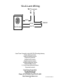
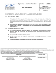
INSTALLATION/OPERATING INSTRUCTIONS TMC Temperature Monitoring Control Temperature Range -30 to 250°F (-35 to 120°C) The TMC displays and monitors a system's temperature and provides an alarm light and output if the system temperature reaches a critical point. The alarm condition can only be cleared by opening the locking enclosure and pressing the manual reset button. The TMC is ideal for domestic hot water systems (see pg. 5). When the domestic water temperature rises above the selected set point, the TMC will enter the alarm mode. The TMC will control a Normally Closed solenoid valve. In the alarm mode, the solenoid valve will shut down the flow of hot water into the domestic system. To open the solenoid valve and let the hot water back into the system, two things must happen: the domestic water temperature must fall below the critical point, and the manual reset button must be pressed. Other typical uses of the TMC include: • Freeze condition alarms • Refrigeration system alarms • Hydronic heating systems high temperature alarms and control for solenoid valve to disable the heating system • Space temperature alarm systems In areas where power losses are common, the TMC can be ordered with a battery backup. This will prevent the need for manually resetting the system whenever there is a power failure. The battery backup will keep the TMC active for approximately two hours and will recharge when power is restored. The TMC can also be ordered in a weatherproof enclosure for mounting outdoors or other areas which require a NEMA-4 enclosure. ACCESSORIES • 120VAC Normally Closed Solenoid valve available in sizes 1/2" to 2" • 1/2" NPT x 3/8" Brass Well HT #904011-00 • Visual/Audio Alarm HT#925011-00 (see pg. 8 for wiring) SPECIAL ORDER • Battery backup provides up to 2 hours of operation if 120VAC power fails. Battery recharges when power is restored. • NEMA-4 enclosure for mounting outdoors • TMC may be ordered for pressure or humidity applications LIMITED ONE YEAR WARRANTY This Heat-Timer device was thoroughly tested for defects and workmanship before leaving our factory. We do warrant the equipment to be free of defects under normal use for a period of one year from the date of installation. Transportation charges for factory repairs must be prepaid. Damage to the Heat-Timer device or any of its components due to misuse, abuse, improper installation, or caused by power failures, fire, flood, or lightning are not covered by this warranty. The company assumes no liability for indirect or consequential damages of any nature. This Heat-Timer warranty applies only to the original purchaser/user, is not assignable or transferable, and does not cover damage to the device occurring in shipment. Any service, repairs, modifications or alterations to the unit not expressly authorized by the company will invalidate the warranty. This warranty is in lieu of all other warranties expressed or implied. 1 INSTALLATION Mounting • The mounting site should be flat, strong enough to hold the TMC, and no more than 500’ from the sensor. • Mount the unit away from excessive heat or cold. Ambient operating temperature is from 20°F to 120°F. • The enclosure has one keyhole mounting tab extending from the top of it and two mounting tabs extending underneath. Use all three tabs to secure the unit. • DO NOT drill any holes into or through the enclosure. Installing the Temperature Sensor • • • • The temperature sensor wires can be extended up to 500’ by splicing with 18 gauge shielded wire. Do not run wires in conduit with line voltage. If measuring liquid temperature, the sensor should be inserted into a 3/8” ID well (HT#904011 or equivalent). The TMC will operate based on the temperature it reads at the sensor location. Therefore, select a sensor location which is representative of the entire system. • The sensor wires must be connected to the two terminals 11 and 14 marked SENSOR (see opposite page). • Polarity is not important. Either wire from the sensor can be connected to either input terminal. Power Connections • The TMC requires 120VAC 60hz. • Connect to the left most input terminals 1 and 12 (see opposite page). Wiring a Normally Closed Solenoid Valve (Hot Water Systems) • The solenoid valve is designed to shut off the flow of hot water to the system (see Typical Application on pg. 5). • The solenoid valve should be Normally Closed (NC). This means when there is no power applied to the solenoid valve, it will be shut. The TMC will power the valve open and allow hot water to pass into the system only when the temperature is below the set point and the manual reset button has been pressed. • The solenoid valve power should be switched through output terminals marked NORMAL and COM. These are either terminals 5 and 6 or terminals 8 and 9 (see opposite page). Wiring an Alarm • The alarm output will be active whenever the system temperature has risen (or fallen if in the cooling mode) out of range. Even if the temperature then returns to normal, the alarm will not clear until the manual reset button has been pressed. • The alarm power should be switched through output terminals marked ALARM and COM. These are either terminals 6 and 7 or terminals 9 and 10 (see opposite page). Wiring other Outputs • The TMC can be used to activate pumps, heaters, chillers, fans, or any other piece of on/off equipment. • The TMC can also be used for two position control such as a valve actuator or damper motor. • When the TMC is in the Normal mode, the outputs NORMAL and COM will be continuous (both terminals 5 and 6 or terminals 8 and 9). • When the TMC is in the Alarm mode, the outputs COM and ALARM will be continuous (both terminals 6 and 7 or 9 and 10). IMPORTANT WIRING INFORMATION Class 1 wiring must enter the enclosure through a different KO from Class 2 wiring. Double Pole Double Throw relay output is rated for 6A 1/3HP at 120VAC. Outputs are Dry Contacts Only. No voltage is supplied out of terminals 5 through 10. 2 Push the center button to display the set point or differential Alarm light is on when the TMC is in the ALARM mode Digital display reads sensor value constantly LED is on when the TMC is in the NORMAL mode Push these buttons to adjust the set point or differential MANUAL RESET BUTTON Press button to clear ALARM mode if system temperature is within specification 120VAC 1 2 DPDT RELAY OUTPUTS 3 4 5 6 7 8 9 SENSOR 10 11 Solenoid Valve Power NC Solenoid Valve ALARM COM NORMAL ALARM COM NORMAL 120VAC 12 13 To system sensor Alarm Power Heat-Timer Vis-U-Larm, EMS, Noti fact , or other alarm 3 14 15 16 Setting the Operating Modes • Whenever the TMC is powered up, it will display the software version number and then the current operating modes. Each display will remain on the screen approximately 5 seconds. If the modes are correct, there is no need to make any adjustments. • Once the modes have been set for a particular application, they will be retained in memory and will not need to be reset. • Note that if you do change an operating mode, you will need to reset the set point and differential. • An operating mode can only be changed when it is being displayed in the start-up sequence. To restart the sequence it is necessary to remove power to the TMC and then power it again. • Set the operating modes as described in sequence below: °F or °C - Fahrenheit or Celsius Temperature Operation • If the display shows °F then the TMC will operate in Fahrenheit degrees. • If the display shows °C then the TMC will operate in Celsius degrees. • To change the mode, hold down the center button while pushing either the UP or DOWN button to toggle between the displays of °F and °C. • When the correct temperature mode is selected, release the buttons and wait approximately 5 seconds. H or C - Alarm on Hot or Alarm on Cold • If the display shows H then the TMC will enter the Alarm mode when the system temperature rises above the set point. • If the display shows C then the TMC will enter the Alarm mode when the system temperature falls below the set point MINUS the differential. • To change the mode, hold down the center button while pushing either the UP or DOWN button to toggle between the displays of H and C. • When the correct heating or cooling mode is selected, release the buttons and wait approximately 5 seconds. WARNING: When alarming on a Cold system temperature, the alarm will activate at the set point MINUS the differential. For example, with a set point of 34°°F and a differential value of 2°°F, the TMC will enter the Alarm mode when the temperature falls to 32°°F. It is critical that the TMC set point and differential are set appropriately. NOTE: When alarming on a Hot System temperature, the alarm will activate at the set point value. Startup • When the TMC is powered up, it will be in the Alarm mode. • Use the three upper buttons to adjust the set point and differential as described above. • If the system temperature is in the appropriate range, the red LED should be on. If it is not on, the TMC Alarm mode can not be cleared. • Press the lowest button or the Manual Reset Button (see pg. 3). The TMC should enter the NORMAL mode. WARNING: Whenever the TMC loses power, it requires the Manual Reset Button (lowest button, see pg. 3) be pressed. This is a safety feature of the TMC and can not be disabled. NOTE: The TMC can be special ordered with battery backup. The rechargeable battery will keep the TMC active for approximately two hours if power fails. 4 TYPICAL APPLICATION TMC SENSOR HEAT-TIMER TMC 120 CIRCULATING PUMP (CONTINUOUS RUNNING) SOLENOID VALVE (PURCHASED N.C.) COLD WATER TEMPERED WATER TEMPERED WATER CIRCULATING RETURN LINE HEAT-TIMER TEMPERING VALVE HOT WATER OPTIONAL POSITION HOT WATER SUPPLY SOURCE 32" MINIMUM CL 32" MINIMUM LEGEND CL = THERMOMETER = HEAT-TIMER TEMPERING VALVE = GATE VALVE = CHECK VALVE Heat-Timer tempering valve mixes hot water with cold/return water to control the temperature of the water being supplied to the domestic hot water system. The Normally Closed solenoid valve is installed in the hot water line. The TMC sensor is installed in the flow of the water being supplied to domestic system. The sensor should be located 6 to 10’ past the valve but before any takeoffs. If the TMC registers the domestic water temperature has risen above the maximum acceptable temperature, the TMC will enter the Alarm mode. The solenoid valve will shut and prevent the hot water from entering the system. The alarm will sound to alert staff. Once the problem has been corrected, the manual reset button must be pressed and the domestic system can return to normal operation. 5 OPERATION CONTROL EXAMPLE Set Point Differential 120 °F 2°F Alarm on H ot Alarm on C old On a rise in Temp to 120 °F Alarm Mode Active Alarm light is ON LED is OFF --------------------------------Clearing the Alarm Mode Temperature falls to 118°F or below LED is ON Press Manual Reset Button On a fall in Temp to 118°F Alarm Mode Active Alarm light is ON LED is OFF --------------------------------Clearing the Alarm Mode Temperature rises to 120°F or above LED is ON Press Manual Reset Button Adjusting the Set Point • When set to Alarm on Hot (see pg. 4), the TMC will enter the Alarm mode when the system temperature rises to the set point as shown above. • When set to Alarm on Cold, the TMC will enter the Alarm mode when the system temperature falls to the set point MINUS the differential as shown above. • To adjust the set point, use the following steps: 1. TMC should be displaying sensor temperature. 2. Press the upper left button and release it. The display will change to show SP. Wait 2 seconds or press the upper or lower right button and the set point will be displayed (see pg. 3 for button positions). 3. Press and hold either the upper right button to increase the set point, or the lower right button to decrease the set point, until the desired value is displayed. 4. Wait approximately 10 seconds. If the set point was changed, the display will flash. Then the TMC will return to displaying the sensor temperature. (If you don’t want to wait 10 seconds, press the upper left button once to adjust the differential, or twice to immediately display the sensor temperature). Adjusting the Differential • The differential prevents the TMC from short cycling the Alarm mode. • To set the differential, use the following steps: 1. TMC should be displaying the sensor temperature. 2. Press and release the upper left button twice. The display will change to show dIF. Wait 2 seconds or press the upper or lower right button and the set point will be displayed (see pg. 3 for button positions). 3. Press and hold either the upper right button to increase the differential, or the lower right button to decrease the differential, until the desired value is displayed. 4. Wait approximately 10 seconds. If the differential was changed, the display will flash. Then the TMC will return to displaying the sensor temperature. (If you don’t want to wait 10 seconds, press the upper left button once and the sensor temperature will be displayed immediately.) LED Light • The small LED light should be on whenever the TMC is in the Normal mode. • If the TMC is in the Alarm mode and the LED is off, the Alarm mode can not be cleared. This is because the system temperature is outside the safe range of operation (see Control Example above). • If the TMC is in the Alarm mode and the LED in on, the Alarm mode can be cleared by pressing the Manual Reset Button. Alarm Light • The large Alarm Light will be on whenever the TMC is in the Alarm mode. • To clear the Alarm mode and light, the small LED light must be on and the Manual Reset Button must be pressed. 6 TROUBLESHOOTING TEMPERATURE VALUE No Display: Check the 120VAC 60hz power to the TMC. Turn the power off and (in degrees F) (in Ohms) back on. -10 5 9 0 75 OPN Display: The TMC does not see a sensor connected and the Alarm mode will 0 4 2 6 83 10 3 1 2 15 be active. Check the sensor wires are continuous and have not been broken or 20 2 3 0 89 disconnected. Then follow the procedure for Incorrect Temperature Display. 30 1 7 2 64 SHT Display: The TMC sees a short across the input terminals and the Alarm 4 0 1 3 0 40 mode will be active. If you remove the sensor wires from the TMC terminals, 50 9944 the display should change to read OPN. If the display does not change to 60 7653 OPN, the TMC may be damaged. 70 5941 Incorrect Temperature Display: Remove the wires from the SENSOR screws. 80 4649 The display should change to read OPN and the Alarm mode should activate 90 3667 (if it was not already active). If they don’t, the TMC may be damaged. Take an 100 2914 110 2332 ohm reading across the detached sensor wires. The ohm reading should 120 1879 correspond to the chart on the right. If the ohm reading is significantly 130 1524 different, the sensor may be damaged. 1 4 0 1 243 Alarm mode does not activate: Turn power to the TMC off. Turn power back 150 1021 on and check the TMC’s operating modes are correct (see pg. 4). When the 160 842 TMC has finished displaying the operating modes, the TMC should be in the 170 699 Alarm mode. If it isn’t, the TMC may be damaged. 180 583 Alarm mode does not activate at the desired temperature: First complete 190 489 the steps in the previous section. When the operating modes have been set 200 412 210 349 correctly, check the set point and differential values. If the TMC is set to 220 297 Alarm on Hot then the Alarm mode should become active when the tempera230 253 ture rises to the set point. If the TMC is set to Alarm on Cold then the Alarm mode should become active when the temperature falls to the set point MINUS the differential. The Alarm mode can not be cleared unless the system temperature is in the appropriate range as indicated by the LED being on. If the LED is on, pushing the Manual Reset Button should clear the Alarm mode. TMC does not activate an alarm: Remove all connections from terminals 5 through 10 (see pg. 3). If the Alarm mode is not active, turn TMC power off and back on. The red Alarm light should be on. Test for continuity across both pairs of terminals marked ALARM and COM (Terminals 6-7 and 9-10). If there is continuity across the terminals, then the TMC is working correctly. Check the alarm and alarm wiring for the problem. TMC does not open a NC solenoid valve: The red Alarm light must be off and the LED light must be on. Remove all connections from terminals 5 through 10 (see pg. 3). Test for continuity across both pairs of terminals marked NORMAL and COM (Terminals 5-6 and 8-9). If there is continuity across the terminals, then the TMC is working correctly. Check the valve and valve wiring for the problem. 7 Vis-U-Larm Wiring TMC Terminals ALARM COM RED GRAY Vis-U-Larm 120VAC WHITE Heat-Timer Controls for the HVAC/R & Plumbing Industry Steam heating controls Hydronic heating controls Sequencing controls Radiant heat controls Digital set point controls Precision tempering valves VARIVALVE air vents 2, 3, and 4 way motorized valves Snow melt controls Heat-Timer Corporation 20 New Dutch Lane Fairfield, NJ 07004 Phone (973)575-4004 Fax (973)575-4052 http://www.heat-timer.com 8 HT 059242-00 REV A