1
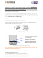
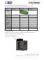
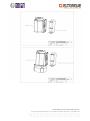
SAFETY INSTALLATION MANUAL QT250 2.2/2.3 Ex Revision Date: 18.08.2014 QT800 2.2/2.3 Ex Ex 150.0002_07 Safety Installation Manual Last changed 18.08.2014 by Tove M. Moe and Bjørn Nybrodahl Page 1 of 13 Table of Contents 1 INTRODUCTION........................................................................................................................................ 3 1.1 1.2 2. GENERAL .................................................................................................................................................. 3 SAFETY INSTRUCTION................................................................................................................................... 3 INSTALLATION ......................................................................................................................................... 4 2.1 MECHANICAL ............................................................................................................................................. 4 2.2 ELECTRICAL................................................................................................................................................ 4 2.2.1 Cable glands and cables .................................................................................................................... 5 2.2.2 Connection of Eltorque Interface connection terminals .................................................................... 5 2.2.3 Technical data for Eltorque Interface connection terminals ............................................................. 6 2.2.4 Ground terminal ................................................................................................................................ 6 3. BEFORE COMMISSIONING........................................................................................................................ 7 4. OPERATION.............................................................................................................................................. 7 5. MAINTENANCE AND SPARE PARTS .......................................................................................................... 8 Ex 150.0002_07 Safety Installation Manual Last changed 18.08.2014 by Tove M. Moe and Bjørn Nybrodahl Page 2 of 13 1 Introduction 1.1 General The Eltorque Actuator is an electric actuator which moves or controls a mechanism or system. The Eltorque actuators are typically used in flow control systems in the maritime industry. The Eltorque actuators offers a compact design, serial interface and high torque at low rpm. The actuators offer a high level of precision in the control of valves, and are easily programmed with respect to torque, speed and turning angle. The main purpose of this Safety Manual is to ensure safety to personnel and surrounding environment under installation, use and maintenance of Eltorque QT 250 & QT800 2.2 EX products. The owner of the installation is responsible for installation of the chosen product, for instance regarding selection of equipment based on ex-zone map, gas group and temperature limits for the gases used. EMC Location Class according to DNV For EMC Location Class B there must, in addition to the actuator, be installed a PSF unit as a filter to obtain compliance to the Class requirements. This filter can be used with both versions 2.2 and 2.3 of the QT 250/800 Ex. For EMC location class A the version QT250/800 2.3 Ex must be chosen. 1.2 Safety instruction The product is marked with the following warning: “Warning – Do not open while energized” All personnel working with equipment and installation in a hazardous area must have proper training, and shall therefore understand the EX-related marking on the label. Under is an example of the label for Eltorque products QT250 2.2 Ex and QT800 2.2 Ex.The 2.3 version has the same properties. Ex 150.0002_07 Safety Installation Manual Last changed 18.08.2014 by Tove M. Moe and Bjørn Nybrodahl Page 3 of 13 Ta -25 ~ +700C Input 110-240 V AC Frequency 50-60 Hz Power, peak 130 W Power, avg 10-20 W Interface input 0 - 5,25 V DC IP 65 (IEC60079-0) IP 68 (10m/72h) (IEC60259) P/N S/N Prod.date dd.mm.yyyy Motor ID Eltorque AS N-7125 Vanvikan Ex e ib mb IIC T4 Gb IECEx NEM 13.0042 Norway Web: www.eltorque.com System SFI Number Loop Bus address WARNING - DO NOT OPEN WHILE ENERGIZED QTXXX 2.2 EX CanOpen Torque max XXX Nm Example of marking label for Eltorque QT 250 & QT800 2.2 EX products. Comments: Ta denotes the interval of the ambient temperature (maximum and minimum temperature) for the environment the equipment can be used. For this equipment Ta= -250 C to +700 C. IIC, the gas group, means that the equipment is certified for use in hazardous areas with gases in group IIC (ignition energy>20 µJ). The equipment can also be used with gas group IIA and IIB, which has higher limits of ignition energy. T4 denotes the temperature class. T4 has a maximum surface temperature of 1350 C in the Ta given. IP 65 according to Ex demands and IP 68 functionally referring to classification and testing standards. Both Actuator and Interface box has this marking plate. 2. Installation All installations of Eltorque Ex-products shall at least follow requirements in IEC 60079-14. 2.1 Mechanical Installation of the Eltorque actuators on valves must be done according to valve manufacturer’s instructions.When assembling interface box and main actuator it is very important to follow User manual for assembling. See also chapter 3 for more information. 2.2 Electrical Note: Electrical installation can only be designed and executed by personnel with the appropriate skills and competence in accordance with local laws and regulations Requirements in IEC 60079-14 shall always be followed. Ex 150.0002_07 Safety Installation Manual Last changed 18.08.2014 by Tove M. Moe and Bjørn Nybrodahl Page 4 of 13 2.2.1Cable glands and cables Eltorque QT 250 & QT800 2.2/2.3 EX products are delivered with plastic dust cover plugs, and not cable glands, for the connection points for electrical connection and interface. These plastic covers must be removed and replaced with Ex-proof blinding glands or Ex-proof cable glands, M20. Cable glands used must be certified for Ex e, must be appropriate for. Pay special attention to the cable inner and out diameter when choosing cable glands. Make sure to mount the cable glands according to the instructions from the manufacturer. The temperature rise at the location of the cable glands in normal operation is ΔT = 20 ˚C. This must be accounted for when choosing cable glands. Thus, cable glands must be specified for operational temperature of at least <intended operational temperature> + ΔT. For an operational temperature of +70 ˚C, the cable glands must be specified for +90 ˚C. For correct choice of cable in installation, pay special attention to IEC60079-0, chapter 16.6 and IEC60079-14. 2.2.2 Connection of Eltorque Interface connection terminals Connection of Interface should be executed according to instructions in User Manual QT250 and QT800 Ex CANopen. Following is shown an overview. Dimensioned drawing Terminal for Eltorque programming connection RS 232. Terminal for power connection. Terminal for connection bus-cable IN-OUT and end loop termination. Terminal overview.Terminal for connecting power supply. NOTE: The temperature in product branching and termination point can rise up to +200C in addition to the ambient temperature. Ex 150.0002_07 Safety Installation Manual Last changed 18.08.2014 by Tove M. Moe and Bjørn Nybrodahl Page 5 of 13 2.2.3Technical data for Eltorque Interface connection terminals Following is technical data needed for operating and termination of spring terminals. Phoenix terminals Technical drawing (Gen) Number of Positions Pitch Nominal current Rated voltage EN Nominal voltage (Ex) Connection method Wiring method Strip length Contact surface FCK 2,5/4-STF-5,08 EX 1796018 GFCK 2,5/6-STF-7,62 EX 1796254 FCK 2,5/8-STF-5,08 EX 1796050 4 6 8 5.08mm 7.62mm 5.08 mm 12 A 12 A 12 A 320 V 630 V 320 V 176 V 352 V 176 V Spring-cage conn. Spring-cage conn. Spring-cage conn. Fine-stranded Fine-stranded Fine-stranded 10 mm Tin 10 mm Tin 10 mm Tin 2.2.4 Ground terminal Outside on top of actuator chassis there is a terminal for connecting environmental earth. This shall be connected towards vessels grounding point. Referring to EN IEC 60079-14:2007. Ex 150.0002_07 Safety Installation Manual Last changed 18.08.2014 by Tove M. Moe and Bjørn Nybrodahl Page 6 of 13 3. Before Commissioning Make sure correct mounting of both mechanic and electric connections has been performed according to Installation Manual QT250 and QT800 and Interface user manual QT250 2.2/2.3 EX CanOpen and QT800 2.2/2.3 EX CanOpen. Make sure no cable conductors are fastened or squeezed between interface and actuator chassis when assembling. Make sure all 6 screws for fastening interface box is fastened with the correct torque, 3,5-4 Nm. Elbox screws Elbox screws 4. Operation The actuator is configured to operate according to the load profile of a typical butterfly valve actuator. One opening or closing command consists of a nominal 90 ˚C angular travel in either direction, in which torque is 30% of rated torque for 95% of the travel, and 100% of rated torque for the remaining 5% of travel, the near closed region. Rated torque is required in the area of travel in which the disk of the valve enters or exists the seat. The actuator is protected from overheating by sensor based firmware control. As the inside temperature reaches a certain threshold, the actuator is brought to a halt until the temperature has fallen sufficiently enough to run a new complete cycle. For an ambient temperature of 70 ˚C, and after using the actuator in continuous operation, the duty cycle is approximately 20%. That is, for each cycle of opening-closing-opening, the actuator is forced to rest for that run time multiplied by 5. Consequently, when the ambient temperature is 55 ˚C, the maximum duty cycle is higher. The Figure underneath provides an estimated dutycycle (y-axis) as a function of ambient temperature (x-axis) for nominal factory settings (ie. torque settings according to the above description and near closed region of 5%). Ex 150.0002_07 Safety Installation Manual Last changed 18.08.2014 by Tove M. Moe and Bjørn Nybrodahl Page 7 of 13 Note that this dutycycle applies for nominal factory settings, which are set according to European Standard EN 15714-2:2009 Industrial valves – Actuators – Part 2: Electric actuators for industrial valves – Basic requirements. If the actuator configuration is changed, the duty cycle will change accordingly. 5. Maintenance and Spare Parts The QT250 & 800 2.2/2.3 Ex products are maintenance free. All bearings and gears are lifetime lubricated and components are designed to last throughout the actuator’s intended lifetime. It is recommended that the actuator is inspected regularly, at least once a year, to reveal any damages caused by mechanical impact due to risk of corrosion, malfunction etc. It is recommended to regularly control cable entrance, blind glands and cable glands used on interface box for mechanical damages and other strains that will appear over time. The plastic lid on the actuator must be kept dustfree. Eltorque recommends to wipe off the lid with a damp cloth once a month, or more often if necessary. If replacement of the interface box is needed make sure that P/N on the marking on the actuator and the spare interface box matches. In addition Motor ID on the Spare Interface box should be “Spare part”. Ex 150.0002_07 Safety Installation Manual Last changed 18.08.2014 by Tove M. Moe and Bjørn Nybrodahl Page 8 of 13 The QT250 2.2/2.3 EX actuator has conformance only if the parts are marked as follows: The actuator is marked EX250.002.2 for QT250 2.2 Ex and EX250.0002.3 for QT250 2.3 Ex and this marking is also on the interface box. The motor ID on the interface box does not contain the text “Spare part”. or The actuator is marked EX250.002.2 for QT250 2.2 Ex and EX250.0002.3 for QT250 2.3 Ex and the interface box is marked EX250.025.2 as shown in the picture below. The motor ID on the interface box contains the text “Spare part”. Other combinations means the product is non-conformant and should not be used. The QT800 EX 2.2/2.3 actuator has conformance only if the parts are marked as follows: The actuator is marked EX800.002.2 for QT800 2.2 Ex and EX800.0002.3 for QT800 2.3 Ex and this marking is also on the interface box. The motor ID on the interface box does not contain the text “Spare part”. or The actuator is marked EX800.002.2 for QT800 2.2 Ex and EX800.0002.3 for QT800 2.3 Ex and the interface box is marked EX800.025.2 as shown in the picture below. The motor ID on the interface box contains the text “Spare part”. Other combinations means the product is non-conformant and should not be used. Ex 150.0002_07 Safety Installation Manual Last changed 18.08.2014 by Tove M. Moe and Bjørn Nybrodahl Page 9 of 13 Ex 150.0002_07 Safety Installation Manual Last changed 18.08.2014 by Tove M. Moe and Bjørn Nybrodahl Page 10 of 13 EX150.0002_07 Safety Installation Manual x Schedule drawing Related drawing to schedule drawing # EXAAA.NNNN Document regarding QA General documentation X QT 250 2.2 Ex QT 250 Exde X QT 800 2.2 Ex QT 800 Exde X QT 250 2.3 Ex X CanOpen X QT 800 2.3 Ex X Digital PSF Document history Version Change description 0 1 2 3 Document established Clarification around Cable glands Removal digital version Added duty cycle description and temperature limitations in cable glands. 4 Changed marking plate 5 Updated text on spare parts. 6 Clarified description of operation 7 Included version 2.3 Referenced documentation Eltorque: Changed by TR/TMM BN TMM ERB Change date 17.10.13 21.10.13 06.11.13 26.11.13 Approved by BN TMM TSØ BN Approval date 17.10.13 21.10.13 06.11.13 26.11.13 TMM SH ERB BN 02.12.13 04.12.13 10.12.13 10.08.14 BN BN SH TMM 02.12.13 04.12.13 10.12.13 10.08.14 Ex150.0001 User Manual QT250_800_2.2_2.3 Ex Referenced documents standards: EN IEC 60079-0:2011 Explosive atmospheres – Part 0: Equipment – General requirements EN IEC 60079-7:2006 Explosive atmospheres – Part 7: Equipment protection by increased safety “e” EN IEC 60079-11:2011 Explosive atmospheres – Part 11: Equipment protection by intrinsic safety “I” EN IEC 60079-18:2009 Explosive atmospheres – Part 18: Equipment protection by encapsulation “m” EN IEC 60079-14:2007 Electrical installations design, selection and erection Ex 150.0002_07 Safety Installation Manual Last changed 18.08.2014 by Tove M. Moe and Bjørn Nybrodahl Page 11 of 13 Eltorque AS N-7125 Vanvikan Norway Phone: +47 74 85 55 20 Web: www.eltorque.com Ex 150.0002_07 Safety Installation Manual Last changed 18.08.2014 by Tove M. Moe and Bjørn Nybrodahl Page 12 of 13