1
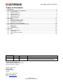
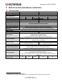
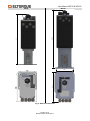
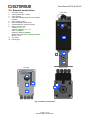
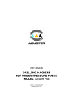
User Manual MT50 & MT150 Electrical Multi-turn Valve Actuators Revision Date: 04.03.2011 Author: Tor Erik Næbb User Manual MT50 & MT150 Page 2 of 27 Revision date: 04.03.2011 User Manual MT50 & MT150 TABLE OF CONTENTS 1. Introduction ................................................................................................................................................. 4 2. Specifications and manual operation ....................................................................................................... 5 2.1 Technical data .................................................................................................................................... 5 2.2 External construction .......................................................................................................................... 7 2.3 Valve operation .................................................................................................................................. 8 2.4 Operating conditions .......................................................................................................................... 9 2.5 Actuator duty type .............................................................................................................................. 9 2.6 Manual operation.............................................................................................................................. 10 3. Installation ................................................................................................................................................. 11 3.1 Mounting actuator on valve .............................................................................................................. 11 3.2 Electrical installation MT50 .............................................................................................................. 14 3.3 Configuration of actuator .................................................................................................................. 16 3.4 Selecting correct configuration ......................................................................................................... 18 4. Maintenance, service and troubleshooting ........................................................................................... 20 4.1 Maintenance ..................................................................................................................................... 20 4.2 Spare parts ....................................................................................................................................... 20 4.3 Troubleshooting................................................................................................................................ 21 5. Appendix ................................................................................................................................................... 22 5.1 Ordering information ........................................................................................................................ 22 5.2 Terminology...................................................................................................................................... 22 5.3 Control system examples ................................................................................................................. 23 5.4 Notes ................................................................................................................................................ 26 Revision history Revision date Done by 06.09.2010 TEN 04.03.2011 TEN Approved by - Changes Changed company logo Changed front page image. Added maximum number of turns under Technical Data. Referenced documentation Technical Manual_Eltorque Interfaces Eltorque Manager 3 Manual Contact information: Eltorque AS N-7125 Vanvikan Norway Phone: +47 74 85 55 20 Fax: +47 74 85 55 12 Web: www.eltorque.no Page 3 of 27 Revision date: 04.03.2011 User Manual MT50 & MT150 1. INTRODUCTION Eltorque is a model range of electric valve actuators suitable for use in a wide variety of industrial environments. The Eltorque actuators are characterized by: Compact size and good torque to size/ weight ratio Flexible control interfaces for easy integration with a wide range of control systems Low power consumption Electronic configuration of speed, torque and other parameters Easy and cost effective installation Maintenance free The Eltorque MT actuators are suitable for remote control of Rolls-Royce Marine UT multi-turn bilge and Cross-over valve manifolds. The actuators are designed for both easy new-installation and retrofit. The MT50 & MT150 can be controlled remotely by two different types of control interfaces: Digital (Open-Close) CANopen (Fieldbus, max/ recommended 127/ 50 actuators per network) For more details about the functionality of these Control Interfaces, refer to the “Technical Manual Eltorque Interfaces”. Additionally, the actuators can be configured and controlled from a computer using a dedicated cable and software tool; Eltorque Manager 3. Fig. 1: MT150 on 6xND125 X-over manifold Page 4 of 27 Revision date: 04.03.2011 User Manual MT50 & MT150 2. SPECIFICATIONS AND MANUAL OPERATION 2.1 Technical data 1 Torque 1 Valve stem speed Valve applications Closing time 2 1 Dimensions (H/W/D) Weight Encapsulation Operation temperature Color Over/ under temperature protection Supply voltage Power consumption Cable glands Control interfaces Position sensor Configuration Configurable parameters Manual operation Number of turns Closed - Open 1 2 MT50 1.0 MT150 1.0 10-50 Nm 50-150 Nm 7-17 rpm 5-15 rpm Rolls-Royce Marine UT multi-turn bilge and X-over valve manifolds, PN10 DN50 DN80 DN100 DN125 DN150 20 sec 25 sec 30 sec 60 sec 65 sec Physical Properties 411/ 115/ 224 mm 550/ 146/ 274 mm 15 kg 28 kg IP68 (5m 1 hr) Corrosion protected aluminium enclosure -25 – 55 C Black and silver Motor current is switched off in case of over-temperature Stator coils utilized as heating elements in case of low temperatures Electrical and Control Properties 110-240 V AC (50/60 Hz) or 125-230 V DC Max: 120W/ 280 VA, Standby: 11W Max: 240W/ 560 VA, Standby: 14W Up to 4 pcs M20 glands allows serial connection of power supply and fieldbus wiring. Threaded holes in actuator capsule. Use IP68 glands for all wires, EMC type for fieldbus wiring. Digital: 2 DI (Open & Close) & 3 DO (Open,Closed & Alarm) CANopen Fieldbus: Max 127 nodes per network, allows positioning and other extended control of actuator. Absolute position sensor, provides correct feedback even after a power failure. Resolution 4,85 °/ Resolution 5,84 °/ Maximum 13 turns Maximum 16 turns USB connection to PC with Eltorque Manager 3 Valve type, Open and Closed positions . Actuator speed, torque and valve position regions. Inverted IO or fieldbus parameters depending on control interface Emergency and safety Standard feature using ergonomic crank shaft. Mechanical valve position indicator. Visual status indication by LED when actuator is powered. Safety function disables motor in case of manual operation while actuator is powered. 39 49 59 70 Configureable using Eltorque Manager 3 Adapted flange bracket and stem connection is required and must be ordered with the actuator Page 5 of 27 Revision date: 04.03.2011 80 User Manual MT50 & MT150 550 MT150 146 274 411 MT50 Fig. 2: External dimensions Page 6 of 27 Revision date: 04.03.2011 User Manual MT50 & MT150 2.2 External construction 1. 2. 3. 4. External housing Cable gland holes 4 x M20 Valve bracket Valve stem adapter with red valve position indicator 5. Valve position scale 6. Manual Operation shaft cover 7. Crank handle for manual operation 8. Status indicator LED Closed = YELLOW Closing = Blinking YELLOW Open = GREEN Opening = Blinking GREEN Stopped or positioned = Flashing GREEN Alarm = RED 9. Top Cover 10. Driving pins Front view 2 1 3 4 5 Top view Bottom view 6 7 10 8 4 9 Fig. 3: External construction Page 7 of 27 Revision date: 04.03.2011 User Manual MT50 & MT150 2.3 About the Rolls-Royce Marine UT valve manifolds The Rolls-Royce Marine UT valve manifolds consist of two or more multi-turn globe valves in five different sizes. The valve size refers to the nominal diameter of the valve, which in turn affects the flow capabilities: - DN50 - DN80 - DN100 - DN125 - DN150 The globe valves can be arranged in bilge manifolds where 2 or 3 valves are aligned in one row. Such valves are always “non-return”, i.e. valve plug is not fixed to the stem and will lie on the valve seat because of Fig. 4: Globe valve components gravity when the valve is opened. Such valves will only allow (Source: Wikipedia – Globe Valve) flow in one direction when the liquid from the pipes underneath the valve manifold lifts the plug upwards. The valves can also be arranged in X-over manifolds where 4 or 6 valves are aligned in 2x2 or 2x3 rows. In these manifolds, the plug is fastened to the stem and will be lifted up when the valve is opened. This allows flow in both directions. Fig. 5: 1-box 2-cell X-over and Bilge valve manifolds When globe valves are operated, the maximum torque is required near closed position: - Forces from the flowing medium will push the plug up or downwards depending on flow direction. Note: The force will increase with both pressure and valve size. - Friction in the bonnet and stem threads increases both when the plug is in contact with the body and with forces applied by the flowing medium. Note: The valves are equipped with a grease nipple for lubrication of valve stem threads, it is important that grease is applied regularly to ensure friction in the threads is kept as low as possible. The MT actuators are equipped with electronic torque sensor to ensure that the actuator stops in case the valve’s operation torque becomes too high. Note: When the actuator is configured during the installation, it is important that its torque/ force limits are set according to valve size and pressure. This procedure is described in section 3.3. Page 8 of 27 Revision date: 04.03.2011 User Manual MT50 & MT150 2.4 Operating conditions The MT50 & MT150 1.0 is especially suitable for use below deck on ships and other offshore vessels due to its compact design, low power consumption and robust construction. It can also be used in other applications as long as the following criteria’s are met: Operating temperature is kept within specified limits. Actuator is placed indoors and not exposed to direct sunlight. Protected from extensive corrosive atmospheres like on open deck of ships or other areas exposed to salt water spray. Cleaning or pollution with strong alkaline or acidic chemicals can also cause corrosion problems. Actuator must not be placed in hazardous areas where the presence of explosive atmospheres might cause explosion hazard. 2.5 Actuator duty type When electric valve actuators operate, they generate internal heat due to thermal loss in motor and –control electronics. The MT actuators combine low power consumption with high efficiency to ensure that internal thermal loss is kept low. Still, duty cycle needs to be considered when designing the valve control system to ensure that the actuators can operate the valves without over-heating. In case the actuator’s internal temperature becomes too high, it will send out an alarm signal via the control interface. Should the temperature continue to rise, the actuator will shut down the motor until temperature decreases to a safe level. To avoid problems with over-temperature alarms and actuator shutting down, duty cycle requirements should be considered before selecting actuator. trest tpos trest tpos Valve position tclose Time Fig. 6: Open-Close and positioning duty Actuators used for Open-Close duty either open or close the valves, intermediate positions are not approached. The valves are rarely operated and the interval between operations may be a few minutes or even several months. Open-Close duty will be relevant for MT actuators with Digital control interface. Actuators used for positioning duty will approach defined intermediate positions to set a static flow through a pipeline, applicable positions also include Open and Closed. Positioning duty will be relevant for MT actuators with CANopen Interface. For both these duty types, the same maximum continuous running time (tclose or tpos) is 5 minutes followed by a rest period (trest) of minimum 5 minutes. The duty type limitations stated above applies for maximum operation temperature, and torque, see section 2.1. If operating temperatures and or torque are lower, the actuator can be operated more than the duty type limitations stated above. Page 9 of 27 Revision date: 04.03.2011 User Manual MT50 & MT150 2.6 Manual operation In case of power failure, control system error or another fault preventing normal operation of the actuator, it can be operated manually without the need of additional tools: 1. Unscrew and remove Manual Operation shaft cover. Fig. 7: Removing MO shaft cover. 2. 3. 4. 5. Attach crank handle on MO shaft. Turn Clockwise to close or Counter-clockwise to open valve. Valve position can be seen on the visual indicator scale. When MO is completed, remove crank handle and refit it onto its holder. 2 Open 3 Close 4 5 Fig. 8: Visual valve position indicator Fig. 9: Manual operation features Page 10 of 27 Revision date: 04.03.2011 User Manual MT50 & MT150 Note: The actuator has a sensor which is sensing that the MO shaft cover is removed. Actuator cannot be operated remotely until the cover is replaced and tightened against the top cover. The actuator’s indicator LED will be Red when cover is removed and motor current will be switched off. 6. Refit and tighten MO shaft cover until it stops against top cover. Fig. 10: Refitting MO shaft cover 3. INSTALLATION 3.1 Mounting actuator on valve The RRM UT valve manifolds and MT actuators must be mounted with the valve stem vertically and facing upwards. Before mounting actuator, please make sure there is sufficient space for installation, service and manual operation above and around it: Fig. 11: Space for installation, service and manual operation Page 11 of 27 Revision date: 04.03.2011 User Manual MT50 & MT150 1. 2. Remove hand-wheel for manual operation. Unscrew and remove the 4 fastening screws for the valve bonnet. Note: These screws must be discarded as longer ones are required to fasten the actuator. 1 2 Fig. 12: Removing hand-wheel and fastening screws. 3. 4. Fit the valve stem adapter onto the valve stem and fasten it with the hand-wheel nut, ref. item 1 above. Make sure the grease nipple on the valve bonnet is oriented as shown on the illustration. In case orientation is wrong, use a screwdriver or similar to bend the bonnet plate upwards, turn the bonnet correctly and push it down. 3 4 Fig. 13: Installing valve stem adapter. 5. Lower the actuator onto the valve ensuring that the driving pins fit into the holes of the valve adapter. Fig. 14: Lowering actuator onto valve. Page 12 of 27 Revision date: 04.03.2011 User Manual MT50 & MT150 6. 7. Use the crank handle and turn the manual operation shaft to align the actuator’s fastening holes with the valve’s fastening holes. See section 2.6 for more information. Fasten the actuator with the supplied screws and washers. Fig. 15: Fastening actuator. Page 13 of 27 Revision date: 04.03.2011 User Manual MT50 & MT150 3.2 Electrical installation Note: Electrical installation can only be designed and made by personnel with the appropriate skills and competence. Ensure all such work is done according to applicable laws and regulations. 1. 2. Loosen top cover fastening screws, 4 pcs. Remove top cover by pulling is straight out. Note: Make sure top cover gasket does not fall out 1 Fig. 16: Removing top cover Page 14 of 27 Revision date: 04.03.2011 User Manual MT50 & MT150 L 4 N G 3 4 1 2 3 4 5 6 7 8 1 2 3 4 5 6 7 8 L N G 3 Fig. 17: MT50 Connection terminals location Fig. 18: MT150 Connection terminals location Note: Make sure fuses are disconnected before connection of power supply cables is started. 3. Install the power supply cables through the cable glands on the right side and connect them to the L, N and G/ PE terminals. Fig. 19: Operation of L-N-G/PE terminals 4. Install the control signal cables through the cable glands on the left and connect them according to specification in Fig. 21. Fig. 20: Control Signal terminals operation. CANopen Control Interface Open Common Out Closed Open Alarm GND GND CAN_H CAN_L Bridge for terminal resistor 2 3 4 5 6 1 2 3 4 7 8 5 CAN_L Close 1 Outgoing CAN_H Common In Incoming GND Digital Control Interface 6 7 8 Fig. 21: Control signal connection terminals. Control Interface functionality, cable recommendations etc. are described in ”Technical Manual_Eltorque Interfaces”. Page 15 of 27 Revision date: 04.03.2011 User Manual MT50 & MT150 3.3 Configuration of actuator The MT50 and MT150 actuators are configured electronically using the Eltorque Manager 3 software and a USB configuration cable. Manager 3 is distributed by e-mail or can be downloaded from our website, while the configuration cable can be purchased from local Eltorque distributor or the head office in Norway. (See page 3 for contact information) The following parameters can be configured: End positions – Closed and Open. Speed, Torque and Near Closed region. Fieldbus address/ Node ID for CANopen. Inversion of input and output for Digital. End positions and fieldbus address are mandatory, while the other parameters can be changed to achieve better valve control performance. 1. Install Eltorque Manager 3 and if required driver for configuration cable on your computer. 2. Connect configuration cable to a USB port on your computer. Start Manager 3 Driver: Manager 3 Installation file: Fig. 22: Eltorque Manager 3 installation files 3. 4. Connect cable to Actuator’s configuration connector. Note: Make sure actuator is powered before attempting to connect actuator with Eltorque Manager 3. 4 Fig. 23: Eltorque configuration cable Fig. 24: Configuration cable connector Page 16 of 27 Revision date: 04.03.2011 User Manual MT50 & MT150 5. 6. Press Connect to establish communication with the actuator. Select appropriate configuration values depending on valve and control system, see section 3.4 for more information. Note: Make sure valve type is set correctly in actuator before setting Closed and Open positions. 7. Press Hall disable to disable the Manual Operation shaft cover sensor. 8. Press CW rot and actuator will automatically rotate clockwise until it finds closed position. Note: If valve is closed when actuator is mounted on the valve, use crank handle and turn the manual operation shaft 10 turns counter-clockwise before pressing CW rot. 9. Press Set C&O and Closed is set to the current position, while Open is set a certain number of turns counter-clockwise according to valve type. 10. Press Open to open valve and check that actuator operates correctly. 11. Press Close to close valve again. 12. Disconnect configuration cable and refit top cover. 6 6 11 10 6 8 9 5 7 Fig. 25: Eltorque Manager 3 screenshot. For more information about the functionality of the software, please refer to the Eltorque Manager 3 Manual. Page 17 of 27 Revision date: 04.03.2011 User Manual MT50 & MT150 3.4 Selecting correct configuration The MT50 & MT150 offers an easy but advanced configuration set-up, which allows accurate adjustments depending on valve and control system characteristics. Fig. 26: Torque/ force, speed, region settings and Indicator LED functionality. As described in section 2.3, the force required to operate valves is depending on the pressure of the flowing medium, which can be calculated by the following formula: P F F PAN A where - F is the force in N - P is the pressure - A is the area of the flow Page 18 of 27 Revision date: 04.03.2011 User Manual MT50 & MT150 By applying this formula to the RRM UT valves, closing force can be calculated. Due to friction in valve stem threads and other uncertainty factors, the required valve force has been multiplied by a safety factor of 1,5 in the table below. Valve size DN50 DN80 DN100 DN125 DN150 The actuator’s torque/ force settings is a value between 0 and 100. Corresponding Valve diameter [mm]} 50 80 100 125 150 closing force is found by measuring the Number of turns 5 7 9 14 16 Valve area [mm2] 1963 5027 7854 12272 17671 actual force on the valve plug on new well-lubricated valves. Pressure [bar] Closing Force [kN] Over time it is lightly that the force will 1 0,3 0,8 1,2 1,8 2,7 decrease 2 0,6 1,5 2,4 3,7 5,3 3 0,9 2,3 3,5 5,5 8,0 4 1,2 3,0 4,7 7,4 10,6 5 1,5 3,8 5,9 9,2 13,3 6 1,8 4,5 7,1 11,0 15,9 7 2,1 5,3 8,2 12,9 18,6 8 2,4 6,0 9,4 14,7 21,2 9 2,7 6,8 10,6 16,6 23,9 10 2,9 7,5 11,8 18,4 26,5 MT50 MT150 Torque setting Closing Force [kN] 0 1 14 10 2 15 20 3 16 30 4 17 40 5 18 50 6 19 60 7 20 70 8 21 80 9 24 90 12 27 100 14 29 - - Under Fieldbus settings you can set the Node ID of actuators with CANopen Control Interface. It is important that all actuators in the network have a unique Node ID and that it is set correctly according to the layout of the control system. In case the actuator has a Digital interface, the Fieldbus settings will be replaced by settings related to inversion of input and output signals. Refer to Technical Manual_Eltorque Interfaces for more information. Page 19 of 27 Revision date: 04.03.2011 User Manual MT50 & MT150 4. MAINTENANCE, SERVICE AND TROUBLESHOOTING 4.1 Maintenance The MT50 & 150 is in principle maintenance free; all bearings and gears are lifetime lubricated and components are designed to last throughout the actuator’s lifetime. It is however recommended that the actuator is inspected regularly to reveal any damages caused by mechanical impact, corrosion etc. Top cover gasket and manual operation shaft seal should be lubricated with suitable lubricants if they appear to be dry. 4.2 Spare parts 1. Control Interfaces: Part No. Description MT50.020.1 MT50 CANOPEN INTERFACE 1.0 MT50 DIGITAL INTERFACE 1.0 MT150.020.1 MT150 CANOPEN INTERFACE 1.0 MT150 DIGITAL INTERFACE 1.0 Note: If control interface is replaced, it must be reconfigured using Manager 3 as described in section 3.3. 1 1 Fig. 27: MT Control interfaces Page 20 of 27 Revision date: 04.03.2011 User Manual MT50 & MT150 4.3 Troubleshooting Problem description No response from actuator either on the control system or if you connect with Manager 3. No light in the indicator LED. Actuator’s alarm output is active, on a fieldbus system it gives torque alarm. The actuator attempts to move valve when a control signal is given. Indicator LED is RED. Actuator is able to operate the valve but the operation time is longer or shorter than desired. Actuator’s alarm output is active, on a fieldbus system it gives temperature alarm. The actuator responds normally to control signals. Indicator LED is RED. Actuator’s alarm output is active, on a fieldbus system it gives temperature alarm. The actuator does not respond to control signals. Indicator LED is RED. The actuator does not respond to control signals. On a fieldbus system, the actuator is not available. Indicator LED is “normal”. Actuator with fieldbus interface does not respond to control signals. The actuator responds normally when tested with Manager 3. Indicator LED is “normal”. Actuator with digital interface does not respond normally to control signals. The actuator responds normally when tested with Manager 3. Indicator LED is “normal”. Actuator does not respond neither to control signals nor when tested with Manager 3. Actuator power supply is verified with voltage meter. After replacement of interface, actuator does not operate correctly. Cause & solution No power supply, check fuses and wiring. Supply voltage can be checked using a voltage meter. L-N voltage should be 110-240 V AC (50/60 Hz) or 125-230 V DC Valve operation torque is too high, please check torque by manual operation. Be aware that foreign objects in the pipe can block the valve and that valve torque changes over time. OR Actuator torque has been set too low, increase it by using Eltorque Manager 3 as described in section 3.3. On fieldbus control systems, torque can be adjusted via the fieldbus communication. Change actuator’s speed by using Eltorque Manager 3 as described in section 3.3. On fieldbus control systems, speed can be adjusted via the fieldbus communication. Actuator’s internal temperature is 10 C or less from the motor current shut-down limit. If possible, allow actuator to cool down by leaving it in standby mode for 15 minutes or more. Actuator has over-heated and the motor current is shut down to prevent damage. Make sure surrounding temperature is within limits and that the duty type requirements are followed. See section 2 for more details. Faulty control system, please ask system vendor for support. OR Problem with control signal wiring, please contact local Eltorque agent for support. Incorrect fieldbus settings, please check configuration with Manager 3. OR Fieldbus control system is not wired or configured correctly. Incorrect digital inversion settings, please check configuration with Manager 3. OR Digital control system is not wired or configured correctly. Defective control interface, must be replaced. Interface has not been configured correctly, please refer to section 3.3. Contact local Eltorque agent for support if required. Page 21 of 27 Revision date: 04.03.2011 User Manual MT50 & MT150 5. APPENDIX 5.1 Ordering information Part number Description MT50 1.0 with CANopen Interface for DN50 MT50 1.0 with Digital Interface for DN50 MT50 1.0 with CANopen Interface for DN80 MT50 1.0 with Digital Interface for DN80 MT50 1.0 with CANopen Interface for DN100 MT50 1.0 with Digital Interface for DN100 MT150 1.0 with CANopen Interface for DN125 MT150 1.0 with Digital Interface for DN125 MT150 1.0 with CANopen Interface for DN150 MT150 1.0 with Digital Interface for DN150 5.2 Terminology Term Valve Valve actuator Valve flange Valve adapter Control Interface Configuration Hazardous area PLC Digital Control Fieldbus Control CANopen Description A valve is a device that regulates the flow of materials (gases, fluidized solids, slurries, or liquids) by opening, closing, or partially obstructing various passageways. This manual mostly refers to quarter-turn valves with a 90 degrees movement between Closed and Open position. An electric device for operation of valves in various process control systems. The surface of the valve which the actuator is fastened to. Most commonly it is holes for 4 screws, where hole size and distance between them is defined in EN ISO 5211 standard. A device used to connect the actuator to the valve spindle/ stem. Electronic device controlling the valve actuator according to signals from an overall control system. e.g. PLC or other type of electronic controller. The set-up of parameters, which affects the actuator’s performance and behaviour. Area in which the permanent or periodical presence of explosive substances causes a risk of explosion. A Programmable Logic Controller is a digital computer used for automation of industrial processes, such as control of machinery on factory assembly lines, measurement and control of process plants etc. Simple control utilizing relays, on/ off switches and indicators. Allows only Open or Closed functionality for a valve actuator. A fieldbus is an industrial computer network for real-time distributed control of various devices, including valve actuators. When Eltorque valve actuators are controlled by Fieldbus, the functionality is extended in terms of positioning, commands, feedback and configuration. The Eltorque CANopen interface is using the CAN (Controller Area Network) communications standard. CANopen is a fieldbus which allows communication between max 127 actuators connected to the same network. It is not a “master-slave” network (ref. Modbus), hence all nodes in the network can actively send messages at their own initiative. The communication is prioritized, meaning that urgent messages are transmitted and received before information with lower priority. Compared to Modbus, CANopen has the following advantages: More reliable communication, i.e. it is more likely that the information transmitted is received correctly by the recipient. More nodes pr network, max 127. More control and configuration features available. Page 22 of 27 Revision date: 04.03.2011 User Manual MT50 & MT150 5.3 Control system examples Operator Station 17" touch monitor + compact PC Mounted in PLC cabinet door Master panel ETHERNET LOOP 1 Digital IO PUMP 1 CAN OPEN PUMP 2 Power supply 230VAC 50/60Hz CAN OPEN Fig. 28: Stand-alone valve and pump control with operator stations. Page 23 of 27 Revision date: 04.03.2011 Pump control Start / stop command Started / stopped feedback Failure feedback User Manual MT50 & MT150 Fig. 29: Example of control screen layout. Page 24 of 27 Revision date: 04.03.2011 User Manual MT50 & MT150 Main control system 1 Main control system 2 ETHERNET Ethernet to CANopen Converter for Valve Control Power supply 230VAC 50/60Hz (serial power) CANopen Fig. 30: Valve control system as an integrated part of a larger control system. Page 25 of 27 Revision date: 04.03.2011 Power supply 230VAC 50/60Hz (serial power) User Manual MT50 & MT150 5.4 Notes Page 26 of 27 Revision date: 04.03.2011