1
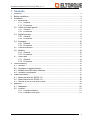
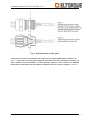
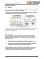
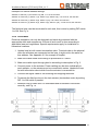
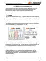
Installation Manual Eltorque actuators - QT250 and QT800 Installation Manual QT250 and QT800_rev C Revision history Revision A B C D E A B C D E Date 17/05-09 28/05-2010 16/11-2010 Done by MG MG MG Approved by First edition Added general field bus description and before installation New logo and document references Other documents 1 2 3 4 5 Usermanual QT250 and QT800 Usermanual QT250 2.0 Usermanual QT800 2.0 Usermanual QT2500 Technical Manual Eltorque Interfaces Document may be subject to change without prior notification. 2 Installation Manual QT250 and QT800_rev C 1 Contents 1 2 3 4 5 6 Contents ................................................................................................................... 3 Before installation ..................................................................................................... 4 Installation................................................................................................................. 4 3.1 Mechanical ....................................................................................................... 4 3.1.1 General .................................................................................................. 4 3.1.2 Procedure .............................................................................................. 4 3.2 Cable and cable glands .................................................................................... 5 3.2.1 General .................................................................................................. 5 3.2.2 Procedure .............................................................................................. 6 3.3 Digital interface................................................................................................. 9 3.3.1 General .................................................................................................. 9 3.3.2 Procedure .............................................................................................. 9 3.4 Analogue ........................................................................................................ 10 3.4.1 General ................................................................................................ 10 3.4.2 Procedure ............................................................................................ 11 3.5 Field bus solution............................................................................................ 11 3.6 Modbus........................................................................................................... 12 3.6.1 General ................................................................................................ 12 3.6.2 Procedure ............................................................................................ 13 3.7 CAN Open ...................................................................................................... 14 3.7.1 General ................................................................................................ 14 3.7.2 Procedure ............................................................................................ 14 Commissioning ....................................................................................................... 15 4.1 General........................................................................................................... 15 4.2 Analogue or digital interface ........................................................................... 16 4.3 Modbus and CAN Open interface................................................................... 16 4.4 Actuator configuration..................................................................................... 17 Order information .................................................................................................... 18 5.1 Spare-parts list for QT250 1.0 ........................................................................ 18 5.2 Spare-parts list for QT800 1.0 ........................................................................ 18 5.3 Service kit for QT250 and QT800................................................................... 19 Appendix................................................................................................................. 20 6.1 Datasheet ....................................................................................................... 20 6.2 Looplist ........................................................................................................... 21 6.2.1 Example Modbus ................................................................................. 21 6.2.2 Example CAN open ............................................................................. 21 3 Installation Manual QT250 and QT800_rev C 2 Before installation For field bus installation there are some rules that need to be followed to ensure that the actuators will work properly: Recommended cable length for Can communication is 300m per, but this depend on quality and dimension of cable. With better quality the cable length can be longer. The loop list should be finalized and approved before installation of cable is started The resistance of the CAN loop should be 120 ohm. If the installation is started in one end of the cable it is a good idea to measure the resistance after each new actuator that is included in the loop, then you are sure that the installation is correct when all actuators are included. 3 Installation 3.1 Mechanical 3.1.1 General Installation of the actuator to the valve should not be carried out, unless the power supply is switched off and disconnected. The actuator can be optionally mounted, but a hanging position should be avoided. The actuator has IP68 as enclosure, which means that the actuator in worst case can be submerged to 5m for 1 hour, but after a situation like this the actuator needs to be cleaned and checked for ingress of water or other liquid.. The actuator should not be mounted in a location where the risk for damages due to external forces is large, i.e. moving goods, waves, stepped on. If this is the situation some extra protection should be installed. Contact supplier for advice. Make sure that the correct actuator is mounted on the correct valve according to looplist 3.1.2 Procedure 1. Place actuator on valve. 4 Installation Manual QT250 and QT800_rev C 2. Adjust the actuator’s adapter and guide-ring to the valve, by turning both the valve and the actuator to closed position. Remove cover to operate handwheel, the arrow in centre of operating wheel is pointing towards ’closed’. Fig. 1. Installation of actuator on valve 3. Fasten actuator to valve by using four screws, size depend on flange interface. 3.2 Cable and cable glands 3.2.1 General Electrical installation can only be designed and made by personnel with the appropriate skills and competence. Ensure all such work is done according to applicable laws and regulations. Special requirements apply for installation in hazardous locations. Cable requirements as follows: Cable parameter Number of conductors Cross section Shield Nominal impedance Capacitance Digital Analogue 7 6 0,5-1,5 mm 2 Not mandatory, but is recommended in case the actuator is placed in conjunction with equipment emitting high levels of disturbances. Modbus CAN Open 1+2 1+2 Twisted pair Twisted pair for for TxD and CAN_H and RxD signals CAN_L signals 2 0,5-1,5 mm The transmission range increases with larger cable cross-section. Yes Requires use of EMC cable glands Max 100 Ω 120 Ω Max 42 pF/m Transmission range increases with lower capacitance. 5 Installation Manual QT250 and QT800_rev C Length related res. Max 100 m/m Max 70mΩ/m Specific line delay Cable length 5 ms/m Max. 1000 m Terminal resistor 500 m Max 500m (baud rate 50kbit/s) Max 250m (baud rate 125kbit/s) Yes, at both ends Table 1. Cable specification 3.2.2 Procedure There are two types of terminals used. On the non-EX versions spring loaded terminals are used, while on the EX-version screw terminals are used. On screw type terminals, it is recommended to use appropriate ferrules for multiconductor wires. On spring-loaded terminals, ferrules are not recommended regardless of wire type Fig. 2. Installation with spring loaded terminals The Eltorque control box has 5 threaded holes for cable glands, 5x M20. 6 Installation Manual QT250 and QT800_rev C Fig. 3. Detailed drawing of cable gland If field bus is chosen as interface the cabling of the signal cable can be done as in Fig. 4. There are incoming and outgoing terminals that are connected internally so that it should not be necessary to have several cables in each terminal. A detailed description of terminals on the different interfaces can be found in chapter 3.3 to 3.7. 7 Installation Manual QT250 and QT800_rev C Fig. 4. Example of cabling on CAN open field bus (only difference on Modbus is termination of bus, this is done by DIP switch on Modbus fieldbus, more info in chapter 3.5) 8 Installation Manual QT250 and QT800_rev C 3.3 Digital interface 3.3.1 General The digital interface allows simple Open & Close operation of valves, i.e. you can command the actuator to close or open the valve. The actuator provides feedback when the valve is closed, open or in alarm status. The connection terminals are located inside the Eltorque Control box. All terminals can accommodate wires of cross section 0,5 - 2,5 mm2. Fig. 5. Digital control interface The Common input terminal (#1) is active and has an internal power supply of 15 V/ 50 mA. Do not attempt to connect an external supply to this terminal as it can damage the control interface. 3.3.2 Procedure Electrical installation can only be designed and made by personnel with the appropriate skills and competence. Ensure all such work is done according to applicable laws and regulations. Special requirements apply for installation in hazardous locations. 1. Make sure cable used is according to specification in Table 1. 2. Make sure cable input through gland is according to description in Fig. 3. 3. Connect power to the actuator. Power cabling can be done individually to each actuator, or the actuators can be connected in series. 4. Connect the signal cable to the input and output terminals. When re-assembling the control box with the actuator, make sure no wires are jammed between the surfaces. It is also recommended to apply some seal lubrication on the gasket to ensure the actuator remains water proof. 9 Installation Manual QT250 and QT800_rev C 3.4 Analogue 3.4.1 General The analogue interface allows control of regulation valves where positioning of the valve is needed. The actuator provides continuous feedback of its actual position, for comparison between desired and actual position. Both positioning and feedback signals are analogue 4-20 mA. The control interface also has a digital alarm output, which is triggered by various failure scenarios. The connection terminals are located inside the Eltorque Control box. All terminals can accommodate wires of cross section 0,5 - 2,5 mm2. Fig. 6. Analogue control interface The analogue input and output are both passive, and need to be powered from the PLC or other type of controller, supply voltage 12-24 VDC. See Fig. 7. 10 Installation Manual QT250 and QT800_rev C Fig. 7. Analog interface connected to analogue controller 3.4.2 Procedure Electrical installation can only be designed and made by personnel with the appropriate skills and competence. Ensure all such work is done according to applicable laws and regulations. Special requirements apply for installation in hazardous locations. 1. Make sure cable used is according to specification in Table 1. 2. Make sure cable input through gland is according to description in Fig. 3. 3. Connect power to the actuator. Power cabling can be done individually to each actuator, or the actuators can be connected in series. 4. Connect the signal cable to the input and output terminals. When re-assembling the control box with the actuator, make sure no wires are jammed between the surfaces. It is also recommended to apply some seal lubrication on the gasket to ensure the actuator remains water proof. 3.5 Field bus solution The actuators with a field bus interface, Modbus or CanOpen can very simplified be described as one signal cable from the control unit and to the first actuator, and then continue to the next actuator and so on until you have a “string” with actuators. Each actuator in the string has a unique address. 11 Installation Manual QT250 and QT800_rev C When a command is sent from the control station and out on the Can bus, the command includes the address of the actuator that is should go to. Each actuator is presented with the command, but only the one that have the unique address that is the same as in the command, will respond. 3.6 Modbus 3.6.1 General The Modbus interface allows control of regulation valves where positioning of the valve is needed. The actuator provides feedback of its actual position, and the operator can regulate the exact position from an operator station or panel if desired, some configuration is also available. Compared to analog or digital interface, a bus solution will reduce the cabling significantly on larger systems. The connection terminals are located inside the Eltorque Control box. All terminals can accommodate wires of cross section 0,5 - 2,5 mm2. Fig. 8. Modbus control interface Bus address is configured by setting the last five DIP switches. The configured address will be the sum of the switches enabled. Fig. 9. DIP switch settings for Modbus control interface 12 Installation Manual QT250 and QT800_rev C Example DIP switch address settings: Address 5: Switch 6 (1) and switch 8 (4) ON, 1+4 =5, the rest OFF Address 15: Switch 6 (1), Switch 7 (2), Switch 8 (4), Switch 9 (8), 1+2+4+8=15, the rest OFF Address 25: Switch 6 (1), Switch 9 (8), Switch 9 (16), 1+8+16=25, the rest OFF Address 30: Switch 7 (2), Switch 8 (4), Switch 9 (8), Switch 9 (16), 2+4+8+16=30, the rest OFF The field bus loop must be terminated in each end, this is done by setting DIP switch 1 to ON. See Fig. 4. 3.6.2 Procedure Electrical installation can only be designed and made by personnel with the appropriate skills and competence. Ensure all such work is done according to applicable laws and regulations. Special requirements apply for installation in hazardous locations. 1. Update loop list with correct termination order. Terminal order is the physical order the actuators are connected on the loop, it might not be the same as bus address. See Appendix 6.2 for example of looplist. 2. Make sure cable used is according to specification in Table 1. 3. Make sure cable input through gland is according to description in Fig. 3. 4. Connect power to the actuator. Power cabling can be done individually to each actuator, or the actuators can be connected in series. Update the loop list with information about which fuse the actuator is connected to. 5. Connect the signal cable to the incoming and outgoing terminals. 6. Terminate the field bus loop in the last actuator (termination order) by setting DIP 1 to ON switch if present. 7. Measure loop to make sure it is terminated and all actuators connected correctly, see Fig. 10. 13 Installation Manual QT250 and QT800_rev C Fig. 10. Measuring loop resistance on Modbus loop When re-assembling the control box with the actuator, make sure no wires are jammed between the surfaces. It is also recommended to apply some seal lubrication on the gasket to ensure the actuator remains water proof. 3.7 CAN Open 3.7.1 General The CAN Open interface allows control of regulation valves where positioning of the valve is needed. The actuator provides feedback of its actual position, and the operator can regulate the exact position from an operator station or panel if desired. Compared to a Modbus solution there are more configuration parameters available on Can-bus The connection terminals are located inside the Eltorque Control box. All terminals can accommodate wires of cross section 0,5 - 2,5 mm2. Fig. 11. CAN Open control interface. The field bus loop must be terminated in each end; this is done by connecting terminal 4 and 5 in the interface box. There are two ways of measuring that the loop is correctly terminated and all actuators are correctly connected, see Fig. 12. 3.7.2 Procedure Electrical installation can only be designed and made by personnel with the appropriate skills and competence. Ensure all such work is done according to applicable laws and regulations. Special requirements apply for installation in hazardous locations. 14 Installation Manual QT250 and QT800_rev C 1. Update loop list with correct termination order. Terminal order is the physical order the actuators are connected on the loop, it might not be the same as bus address. See Appendix 6.2 for example of looplist. 2. Make sure cable used is according to specification in Table 1. 3. Make sure cable input through gland is according to description in Fig. 3. 4. Connect power to the actuator. Power cabling can be done individually to each actuator, or the actuators can be connected in series. Update the loop list with information about which fuse the actuator is connected to. 5. Connect the signal cable to the incoming and outgoing terminals. 6. Terminate the field bus loop in the last actuator (termination order) either by shortening terminal 4 and 5 or by DIP switch if present. 7. Measure loop to make sure it is terminated and all actuators connected correctly, see Fig. 12. Fig. 12. Measuring resistance on complete loop to the left, and on disconnected loop to the right. When re-assembling the control box with the actuator, make sure no wires are jammed between the surfaces. It is also recommended to apply some seal lubrication on the gasket to ensure the actuator remains water proof. 4 Commissioning 4.1 General Commissioning can either be done by customer or by Eltorque service technician. Do not open or close valves without having permission from responsible person on installation. 15 Installation Manual QT250 and QT800_rev C 4.2 Analogue or digital interface 1. Make sure all cabling is done according to specification in chapter 3.2. 2. Test and verify wiring before power is switched on. 3. Power up system. 4. Check that the correct actuators are connected to the valve according to IOlist or drawings. 5. If necessary configure actuator, see chapter 4.4 Actuator configuration. 6. If operating panel is available, test that opening, closure and feedback signals are working. 7. Test stability for at least 24 hrs. 4.3 Modbus and CAN Open interface 1. Make sure all cabling is done according to specification in 2 16 Installation Manual QT250 and QT800_rev C Before installation For field bus installation there are some rules that need to be followed to ensure that the actuators will work properly: Recommended cable length for Can communication is 300m per, but this depend on quality and dimension of cable. With better quality the cable length can be longer. The loop list should be finalized and approved before installation of cable is started The resistance of the CAN loop should be 120 ohm. If the installation is started in one end of the cable it is a good idea to measure the resistance after each new actuator that is included in the loop, then you are sure that the installation is correct when all actuators are included. 2. Installation 3. Make sure bus termination order is documented, i.e. updated in loop list. 4. Test and verify wiring before power is switched on. 5. Power up system. 6. Check that all nodes are available on operator panel. 7. Check that actuators are connected to valves according to loop list, i.e. valve with SFI-number 314-118 connected to actuator with bus address 5. Use termination order to identify actuator and operate actuator from operator station while observing the valve to check for reaction. 8. If necessary configure actuators, see chapter 4.4 Actuator configuration. Actuators are normally configured and labeled with correct Node-ID / bus address and default parameter settings from factory. 9. Test actuator by setting open and closed signal from panel 10. Test stability for at least 24 hrs 4.4 Actuator configuration If commissioning is done by customer, changing configuration cannot be done without purchasing the appropriate service kit. See Chapter 5 Order information, for detailed ordering information. Manual for using configuration tool included in kit. The actuators will be configured with default configuration from factory if nothing else is agreed upon. If appropriate information is received from customer before shipping, the actuators will be configured and labeled with bus-address according to loop list. 17 Installation Manual QT250 and QT800_rev C In addition to parameters seen in Table 2, there are several other parameters available for configuration: - tuning of torque and speed through the different phases between open and closed - changing bus-address and baud rate (after changing Node ID and baud rate, the actuator must be reset by using reset button in Eltorque Manager program) - configuring open and closed position, default 0-90° if actuator is mounted according to specification QT250 QT800 Default Limit Default Limit Operating torque 220 Nm 250 Nm 750 Nm 800 Nm Holding torque 220 Nm 250Nm 500 Nm 800 Nm Opening Time 15 sec. 13-60 sec / 90° 40 sec. 40-180 sec. / 90° Torque Limit switch 0-4° / 200 Nm 0-10° / 30-250 Nm 0-4° / 700 Nm 0-10° / 105-800 Nm Table 2. Default values for configurable parameters 18 Installation Manual QT250 and QT800_rev C 5 Order information To help us process your order, we require some information: Valve type Valve dimension (DN) and pressure (PN) Torque requirements Shaft interface Flange interface Regulation or ON/OFF Interface (Digital, analogue, CANopen or Modbus) Environmental requirements (Open deck, EX or indoor) 5.1 Spare-parts list for QT250 1.0 Item number 250.110.1 250.120.1 250.130.1 250.140.1 250.000.1 250.010.1 250.020.1 250.030.1 250.040.1 Item QT250 1.0 complete actuator with digital interface QT250 1.0 complete actuator with CANopen interface QT250 1.0 complete actuator with analogue interface QT250 1.0 complete actuator with Modbus interface QT250 1.0 quarter turn actuator QT250 1.0 digital interface QT250 1.0 CANopen interface QT250 1.0 analogue interface QT250 1.0 Modbus interface 250.111.1 250.121.1 250.001.1 250.001.1 250.021.1 QT250 2.0 complete actuator with digital interface QT250 2.0 complete actuator with CANopen interface QT250 2.0 quarter turn actuator QT250 2.0 digital interface QT250 2.0 CANopen interface 250.115.1 250.125.1 250.015.1 250.025.1 QT250 2.1 complete actuator with digital interface EX-version QT250 2.1 complete actuator with CANopen interface EX-version QT250 2.1 digital interface EX-version QT250 2.1 CANopen interface EX-version Adapter SQ17x17 – SQ14x14 Adapter SQ14x14 – SQ11x11 10.072 Handle for easier manual operation of actuator Cover for manual operation wheel Other adapters and brackets can be delivered upon request, please contact Eltorque AS. 5.2 Spare-parts list for QT800 1.0 Item number 800.110.1 Item QT800 1.0 complete actuator with digital interface 19 Installation Manual QT250 and QT800_rev C 800.120.1 800.130.1 800.140.1 800.000.1 800.010.1 800.020.1 800.030.1 800.040.1 QT800 1.0 complete actuator with CANopen interface QT800 1.0 complete actuator with analogue interface QT800 1.0 complete actuator with Modbus interface QT800 1.0 quarter turn actuator QT800 1.0 digital interface QT800 1.0 CANopen interface QT800 1.0 analogue interface QT800 1.0 Modbus interface 800.111.1 800.121.1 800.001.1 800.011.1 800.021.1 QT800 2.0 complete actuator with digital interface QT800 2.0 complete actuator with CANopen interface QT800 2.0 quarter turn actuator QT800 2.0 digital interface QT800 2.0 CANopen interface 800.115.1 800.125.1 800.015.1 800.025.1 QT800 2.1 complete actuator with digital interface EX-version QT800 2.1 complete actuator with CANopen interface EX-version QT800 2.1 digital interface EX-version QT800 2.1 CANopen interface EX-version Adapter SQ27x27 – SQ22x22 10.072 Handle for easier manual operation of actuator Cover for manual operation wheel Other adapters and brackets can be delivered upon request, please contact Eltorque AS. 5.3 Service kit for QT250 and QT800 Service kit for Eltorque actuator Additional kit for connecting to CANopen bus loop Additional kit for connecting to Modbus loop 900-01 900-001.1 900-002 QT-series configuration cable for connection to service port on actuator QT-series configuration cable EX-version for connection to service port on actuator QT-series configuration software for PC – Eltorque Manager 2.0 20 Installation Manual QT250 and QT800_rev C 6 Appendix 6.1 Datasheet General QT250 QT800 Power Supply 110 - 230VAC 50/60Hz Power consumption standby Power consumption running Max. 60W Max. 100W Max. 100W Operating Torque (configurable) Max. 250Nm Max. 800Nm Holding Torque (configurable) Max. 250 Nm Max. 800Nm Opening Angle (configurable) Opening Time (configurable) Operation speed (configurable) 0-90 deg. 13-60 sec / 90 deg. 0 -120 RPM 0 -120 RPM -25 to +55 deg.C (1.0) -25 to +70deg.C (2.0) Temperature limits Operating area 40-180 sec / 90 deg. Control of butterfly-, ball- and three-way 0 – 90 valves Butterfly DN50 – DN200 PN16 Butterfly DN200 – DN350 PN16 Valve dimensions Upper dimension limit depends on type of valve and pressure (PN). Shaft size Flange interface 17x17mm 27x27mm F05, F07 and F10 F10 and F12 Duty type Manual operation Mechanical description Weight Enclosure Outer dimensions (WxHxD) S3 50% 15min. 20 turns on crank handle = 90 movement on valve 70 turns on crank handle = 90 movement on valve QT250 QT800 11 kg 21 kg Anodized aluminum (AL6063), Die cast aluminum, ABS antistatic Anodized aluminum (AL6063), Die cast aluminum, ABS antistatic 156x229x210 mm 200x330x230 mm Protection Class Motor IP 68 (5m 1h) QT250 QT800 Construction Number of poles Step motor 48 48 Cooling element Motor current is switched off in case of over-temperature Heating element The motor coils are also utilized as heating elements in case of low temperatures Gearbox QT250 QT800 Construction 3-step planetary gear 4-step planetary gear Transmission 1:82 1:291 Bearings Ball- needle- and bronze bearing Lubrication End-switches Durability calculations Maintenance-free Magnetic absolute encoder with adjustable end points Minimum 120 000 cycles Minimum 30 000 cycles 21 Installation Manual QT250 and QT800_rev C Certificates: QT250 QT800 Type Approval DNV, GL, CCS DNV, GL, CCS EMC Environmental EN 50081-2, EN 50082-2, EN 60945 EN 60529:1991, EN 60068-2-6, IEC 68-2-52, IEC 60068-2-2, IEC 60068-2-30, IEC 60068-2-1) Other Approvals CE-labling 6.2 Looplist 6.2.1 Example Modbus 6.2.2 Example CAN open 22


![User Guide [ ] - American Industrial Systems, Inc.](http://vs1.manualzilla.com/store/data/005740554_1-2a4ebbae5daccebd80088e03c7d32b9b-150x150.png)