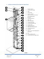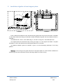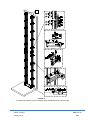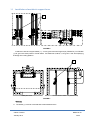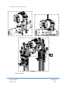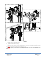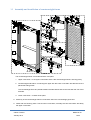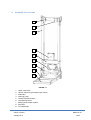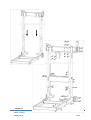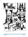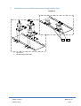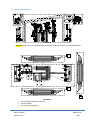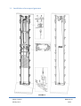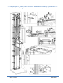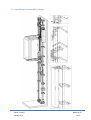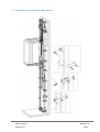
1
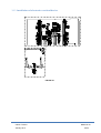
LIFTING PLATFORM
MAISON TRACTION - MRL
Installation manual
maison Traction
January 2014
MA04-22-04
1/23
TABLE OF CONTENTS
1. ABOUT THIS DOCOUMENT
1.1
Document information ........................................................................................................................3
1.2
Safety warning definition ....................................................................................................................3
1.3
Scope of supply ..................................................................................................................................3
1.4
Information concerning the product ....................................................................................................3
1.4.1 Scope of current document ................................................................................................................3
1.4.2 Validity, date and terms considering the specific document ..............................................................4
1.4.3 Manufacturer.......................................................................................................................................4
1.4.4 Definition, type and capacity ...............................................................................................................4
1.5
Quality assurance ...............................................................................................................................4
1.6
Instructions for installation of controller and pre-wiring ......................................................................4
1.7
Transportation & temporary storage ...................................................................................................4
1.7.1 Unpacking of components ..................................................................................................................4
1.7.2 Temporary storage .............................................................................................................................5
1.7.3 Material protection ..............................................................................................................................5
1.7.4 Protection from environmental conditions ..........................................................................................5
2. GENGERAL DESCRIPTION MAISON TRACTION
3. INSTALLATION INSTRUCTIONS
3.1
Installation of landing doors in the shaft .............................................................................................7
3.2
Installation guide rails and support plates ..........................................................................................8
3.3
Installation of machine’s support bases .........................................................................................10
3.4
Machine base installation .................................................................................................................11
3.5
Assembly and installation of counterweight frame ...........................................................................13
3.6
Assembly of car frame ......................................................................................................................14
3.7
Installation of car buffers and counterweight’ buffer base ............................................................17
3.8
Rope attachment ..............................................................................................................................18
3.9
Installation of overspeed governor ...................................................................................................19
3.10
Installation of cams, limit switches, maintenance security system and car and car frame fixing . ...20
3.11
Installation of controller cabinet. .......................................................................................................21
3.12
Installation of counterweight screen .................................................................................................22
3.13
Istallation of electronic overload device. ...........................................................................................23
maison Traction
January 2014
MA04-22-04
2/23
1 ABOUT THIS DOCUMENT
1.1 Document information
Modification no
1
2
3
4
5
6
7
Modification date
Modified by
Legal owner
KLEEMANN HELLAS ABEE
Title
Installation manual maison Traction
Date of issue :
10/02/2014
Language : ENG
Chapter
Created:
Checked:
Translated:
1-3
A.Kermelidis
A.Kermelidis
I.Parcharidis
1.2 Safety warning definition
Danger: Draws attention to a high risk of serious injury or death of persons.
Warning: Draws attention to risk of serious injury or death of persons or extensive damage to
property.
Caution: Draws attention to information containing important instructions. Failure to observe the
instructions can lead to damage and faults.
Important note: Useful information that must be read
1.3 Scope of supply
The lifting platform maison Traction compiles with 2006/42/ EC.
The lifting platform has a specific range of application regarding travel, speed, load, etc. All the
features of fully recorded in the EC type certificate.
1.4 Information concerning the product
1.4.1 Scope of current document
Important note: The current document consists part of the documentation of complete lifting systems
and it concerns lifts type maison traction.
In special cases that decline from the basic version, special procedures need to be followed. If
customers are not able to carry out the task, the aid of the manufacturer should be asked.
maison Traction
January 2014
MA04-22-04
3/23
1.4.2 Validity, date and terms considering the specific document
The current document is valid until the issue of the next version. The version number is depicted on
paragraph 1.1.
1.4.3 Manufacturer
The product is manufactured by:
KLEEMANN HELLAS SA
Located in
KILKIS INDUSTRIAL AREA
P.O. BOX 25 Postal Code 61100 KILKIS, GREECE
1.4.4 Definition, type and capacity
Definition:
Lifting platform
Type:
maison Traction
Capacity:
180 – 450 Kg
Drawings of each order shall be provided from KLEEMANN’s Technical Department.
1.5 Quality assurance
The quality assurance system employed ensures the high level of quality of all KLEEMANN’s
complete lift systems. The ISO 9001:2000 quality assurance system employed by KLEEMANN
incorporates all the detailed systematic activities required for the compliance of the specific product with
all the relevant safety regulations.
The measures of quality assurance, extensions of them, test methods, documentation and important
points that should be checked are set by the installer to its own structural features.
Important note : All necessary documents regarding safety instructions, use and maintenance of lift
components, are contained within the user’s manual, supplied along with every complete KLEEMANN lift
and should always at the disposal of persons involved in the installation and maintenance of the lift.
1.6 Instructions for installation of controller and pre-wiring
Installation instructions for all electrical components are inside the pre-wiring package.
1.7 Transportation & temporary storage
1.7.1 Unpacking of components
Thoroughly check the consignment for any possible damages or missing parts right after reception.
Notify the manufacturer immediately in written for any problems regarding the consignment. Complaints
that are notified to the manufacturer long after the reception of the consignment will not be accepted.
Remove all packing material prior to installation.
maison Traction
January 2014
MA04-22-04
4/23
1.7.2 Temporary storage
Temporary storage should not take place in high humidity environments. Check all packed
components regularly, for the possible existence of condensed water which could cause wear.
1.7.3 Material protection
Caution: The state of the supplied components should be checked at regular intervals, if the storage
is to exceed the suggested period. KLEEMANN will not be responsible for any failure by other parties to
comply with the suggested storage guidelines.
1.7.4 Protection from environmental conditions
The storage area should be dry and free of dust. Protection against time can only be achieved
through proper packaging and storage.
maison Traction
January 2014
MA04-22-04
5/23
2 GENERAL DESCRIPTION MAISON TRACTION
21
1
20
2
3
4
1.
Traction machine
2.
Traction machine base
3.
Cams
4.
Limit switches
5.
Controller cabinet
6.
Guide rail brackets, for car and
counterweight frames.
5
19
6
7.
Car frame
8.
Overspeed Governor
9.
Safety gear
10. Guide rail fishplate
7
11. Counterweight frame
12. Counterweight guide rails
8
13. Car guide rails
14. Counterweight buffer
15. Maintenance security system
9
16. Counterweight screen
17. Car buffer
10
18. Plate for car & counterweight guide
rails support
11
19. Car
20. Car rope wedge socket
12
21. Counterweight rope wedge socket
13
14
15
16
17
18
FIGURE 1
maison Traction
January 2014
MA04-22-04
6/23
3 INSTALLATION INSTRUCTIONS
FIGURE 2
3.1 Installation of landing doors in the shaft
The exact position of the doors is determined by the plan view supplied by the manufacturer.
Suspend a plump line from the shaft ceiling until the pit, secure the plump line and install all the landing
doors. (FIGURE 2)
For more details please refer to door’s installation manual.
Doors can be center or side opening, automatic or semi-automatic
maison Traction
January 2014
MA04-22-04
7/23
3.2 Installation of guide rails and support plates
FIGURE 3
FIGURE 4
Firstly, locate the two plates for the main and auxiliary guide rails to the pit floor as shown in FIGURE
3.Their exact location according to shaft walls is determined after the guide rails are placed as shown in
FIGURE 4.
The distances GLF, GLW1, GLG2, DBG, dbg, X1, X2 and Y2 are given in the shafts plan view.
The support plate must osculate at the pit along it’s length, so it can support the buffers. The plate
has bases on which the cabins and counterweights bases will be mounted.
The distance between guide rail brackets is given in the accompanying drawings of the lifting
platform.
Warning: Correct fixing of the guide rails and of the support plate is crucial because it affects the
positioning of the rest components and thus the lifting platform’s smooth running.
maison Traction
January 2014
MA04-22-04
8/23
i
FIGURE 5
i.
The upper top brackets must be installed, after the adjustment of machine base.
maison Traction
January 2014
MA04-22-04
9/23
3.3 Installation of machine’s support bases
1
FIGURE 6
Install the machine’s support bases (1) – on the guide rails with forged clips (FIGURE 6). On FIGURE
(7) IS given the exact position of both bases. The distances a, MLB, b, are given in the accompanying
drawings of the lifting platform.
1
Shaft plan view
Shaft cross section A-A’(Headroom)
FIGURE 7
Warning:
The bases (1) must be horizontal and leveled between them.
maison Traction
January 2014
MA04-22-04
10/23
3.4 Machine base installation
i
FIGURE 8
i.
Vibration dampers
maison Traction
January 2014
MA04-22-04
11/23
FIGURE 9
With the machine is delivered a set of:
2 plates of elastic rubber 15 mm (i)
The elastic rubbers provide isolation against vibrations. Install them according to FIGURE 8 between
the machine bases and the support bases on the guide rails.
Danger: Tightening of the screws must be stopped when the 15mm thick rubber becomes 10mm
thick.
maison Traction
January 2014
MA04-22-04
12/23
3.5 Assembly and installation of counterweight frame
1
2
3
FIGURE 10
The counterweight frame is consisted of three main parts:
1. Upper cross beam : In the upper cross beam there is the counterweight frame’s diverting pulley
2. Counterweight side beams: connecting the upper with the lower cross beam and above them are
placed the sliding shoes.
The counterweight fillers are placed between the side beams and are secured with the use of two
brackets.
3. Lower cross beam : consists of two parts
Assembly of the counterweight frame must be done within the counterweight guide rails.
Install with the following order: first the lower cross beam, secondly the two side beams and lastly
the upper cross beam.
maison Traction
January 2014
MA04-22-04
13/23
3.6 Assembly of car frame
1
2
3
4
5
6
7
8
9
FIGURE 11
1.
2.
3.
4.
5.
6.
7.
8.
9.
Upper cross beam
Car-Car frame fixing brackets (upper beam)
Side beam
Diverting pulley
Central suspension beam
Overspeed governor
Safety gear activation system
Rucksack
Front side beam
maison Traction
January 2014
MA04-22-04
14/23
FIGURE 12
maison Traction
January 2014
MA04-22-04
15/23
1
FIGURE 13
1. Safety gear adjustment plate
maison Traction
January 2014
MA04-22-04
16/23
3.7
Installation of car buffers and counterweight buffer base
FIGURE 14
1
2
1. Car buffers
2. Counterweight buffer base.
maison Traction
January 2014
MA04-22-04
17/23
3.8 Rope attachment
FIGURE 15
Caution: The spring on the wedge sockets are placed only at the side of the counterweight frame.
1
3
2
FIGURE 16
1. Counterweight frame diverting pulley.
2. Traction sheave.
3. Car frame diverting pulley.
maison Traction
January 2014
MA04-22-04
18/23
3.9 Installation of overspeed governor
FIGURE 17
maison Traction
January 2014
MA04-22-04
19/23
3.10 Installation of cams, limit switches, maintenance security system and car
and car frame fixing
FIGURE 18
maison Traction
January 2014
MA04-22-04
20/23
3.11 Installation of controller cabinet
FIGURE 19
maison Traction
January 2014
MA04-22-04
21/23
3.12 Installation of counterweight screen
FIGURE 20
maison Traction
January 2014
MA04-22-04
22/23
3.13 Installation of electronic overload device
FIGURE 21
maison Traction
January 2014
MA04-22-04
23/23