1
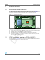
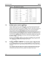
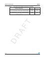
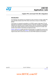
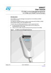
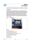
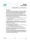
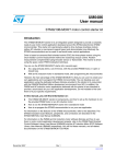
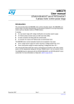
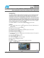
UM0688
User manual
Quick reference of the STEVAL-IHM022V1 STM32 dual motor
drive evaluation board and software demo application
Introduction
The STEVAL-IHM022V1 demonstration board is designed as dual and triple motor control
development platform for STMicroelectronic's ARM Cortex-M3 core-based STM32F103Z
microcontroller. It does include full speed USB2.0, CAN2.0A/B compliant interface, 2
channels I2S, 2 channels I2C, 5 channels USART, 3 channels SPI, 2 channels DAC, internal
64 KB SRAM and 512KB Flash, JTAG&SWD debugging support. The demonstration board
is thought to implement multiple motor control (three MC connectors are present) and, other
than above listed peripherals support, it offers an advanced user I/O interface (LCD QVGA
display and joystick key). Extension headers make it possible to easily connect a daughter
board or wrapping board for your specific application.
Use STEVAL-IHM022V1 as order code for ordering this demonstration board.
Features
■
Four 5 V power supply sources: 2-way screw connector, power jack, USB connector or
daughter board
■
Boot from user flash or system memory
■
64 Mbit serial Flash included
■
Two RS232 channels with RTS/CTS handshake support on one channel
■
USB2.0 full speed connection
■
CAN2.0A/B compliant connection
■
Two motor control connectors full featured for field oriented control plus PFC support on
one connector
■
JTAG, SWD and trace debug support
■
240x320 TFT color LCD
■
Joystick with 4-direction control and selector
■
Reset, wakeup, tamper and user button
■
4 LEDs
■
Extension connectors for daughter board or wrapping area board.
Figure 1.
STEVAL-IHM022V1
AM03551v1
25 March 2009
Rev 1
1/10
www.st.com
Contents
UM0688
Contents
1
2
3
Hardware features . . . . . . . . . . . . . . . . . . . . . . . . . . . . . . . . . . . . . . . . . . . 3
1.1
Demonstration board architecture . . . . . . . . . . . . . . . . . . . . . . . . . . . . . . . 3
1.2
STM32 peripherals mapping on STEVAL-IHM022V1 . . . . . . . . . . . . . . . 3
1.3
Multiple motor control operations . . . . . . . . . . . . . . . . . . . . . . . . . . . . . . . . 4
1.4
Connect STEVAL-IHM022V1 to inverter power stage boards . . . . . . . . . . 4
Software demonstrator . . . . . . . . . . . . . . . . . . . . . . . . . . . . . . . . . . . . . . . 5
2.1
General description . . . . . . . . . . . . . . . . . . . . . . . . . . . . . . . . . . . . . . . . . . 5
2.2
Embedded user interface and debug mode . . . . . . . . . . . . . . . . . . . . . . . . 5
2.3
Memory size and CPU workload . . . . . . . . . . . . . . . . . . . . . . . . . . . . . . . . 5
Demo configuration parameters . . . . . . . . . . . . . . . . . . . . . . . . . . . . . . . 7
3.1
FOC Drive parameters and configuration files . . . . . . . . . . . . . . . . . . . . . . 7
3.2
Demo scope and limitations . . . . . . . . . . . . . . . . . . . . . . . . . . . . . . . . . . . . 7
4
References . . . . . . . . . . . . . . . . . . . . . . . . . . . . . . . . . . . . . . . . . . . . . . . . . 8
5
Revision history . . . . . . . . . . . . . . . . . . . . . . . . . . . . . . . . . . . . . . . . . . . . 9
2/10
UM0688
Hardware features
1
Hardware features
1.1
Demonstration board architecture
The STEVAL-IHM022V1 demonstration board is designed around the STM32F103Z in 144pin TQFP package. A block diagram of the demonstration board is shown in Figure 2; it
illustrates the connections between STM32 MCU and the supported connectors.
Figure 2.
Hardware block diagram
USART2
DC2
DC1
USB
USART1
USART2
MC Sub2
MC_Sub2 Aux
MCU
MC Main
Wakeup Tamper
Joystick
MC Sub1
Reset
LCD
Display
BOOT0
BOOT1
Key
Pot
TRACE
JTAG
CAN
I2C Ext
AM03552v1
In particular, it can be noticed:
1.2
●
3 motor control connectors for supporting up to three 3 phase motor control operations
●
2xUSART, CAN, I2C, USB connectors for external interfacing
●
JTAG/SWD and Trace connectors for debugging and developing applications
●
Embedded user interface constituted by an LCD TFT display and 5-ways joystick key
(plus one additional user defined key).
STM32 peripherals mapping on STEVAL-IHM022V1
The block diagram in Figure 3 illustrates the connection between STM32F103Z peripherals
and the connectors present in the demonstration board.
3/10
Hardware features
Figure 3.
UM0688
MCU peripherals mapping
AM03553v1
1.3
Multiple motor control operations
STEVAL-IHM022V1 demonstration board supports up to three 3-phase brushless motor
control via three 34-pins connectors named MC_Main, MC_Sub1, MC_Sub2, each one
providing all required control and feedback signals to and from a motor power-driving board.
MC_Main and MC_Sub1 connectors include emergency stop, motor speed feedback
(Tacho, Encoder and/or hall sensor), motor currents, DC bus voltage and heatsink
temperature sensing, 6 complementary PWM channels going to the motor driving circuit. As
far as the third motor control connector MC_Sub2 is concerned, the 6 PWM channels can
be derived either by using two general purpose timers working in synchronism or by using
one GP timer plus additional external circuitry for complementary PWM signals generation.
An auxiliary connector (MC_Sub2 Aux) is present on the board for plugging a daughter
board in for this aim.
MC_Main connector features additional sensing signals (AC 50/60 Hz mains and rectified
input current) for managing a digital power factor control, whose software executes in the
same STM32 microcontroller used for multiple motor control.
1.4
Connect STEVAL-IHM022V1 to inverter power stage boards
For simultaneous multiple motor operations, STEVAL-IHM022V1 has to be connected to
three phases inverter power stages through the MC Main, MC Sub1 and MC Sub2 34-pins
connectors.
In our application demo, dual motor control driving has been implemented and two power
stages, MB459 and STEVAL-IHM011V1, available from STMicroelectronics have been
connected to control stage. They can be ordered via ST regional sales offices.
4/10
UM0688
Software demonstrator
2
Software demonstrator
2.1
General description
The demonstration firmware running on STEVAL-IHM022V1 demonstration board is able to
perform dual motor control operations in simultaneous mode. Up to two motors can be
driven in field oriented control (FOC), single shunt resistor and in sensorless mode (no
speed sensor needed).
Dual motor control firmware uses the FOC routines implemented on STM32 PMSM library
ver. 2.0 firmware package and, hence, shares same principles for configuring the motor
drive with user parameters.
Moreover, the architecture of the software has been extended to treat each motor drive as
an independent element, allowing to set the drive and motor parameters in a completely
independent way.
2.2
Embedded user interface and debug mode
An embedded UI (LCD TFT 320x240 display and 5 positions joystick) allows the user to set
a lot of motor control parameters in real time during motors operations. Basically, the UI is
made of:
●
TFT LCD graphical display
●
Micro joystick key with five position
●
One dedicated key for starting/stopping the motors
The user can set all relevant motor drive and control parameters by means a set of screen
views shown on the LCD display.
Debug functionality allows selecting which motor control variables have to be sent via DAC
outputs (2 channels).
2.3
Memory size and CPU workload
Dual motor control software is provided for demonstration purposes and it is not fully
featured as the STM32 FOC motor control library v. 2.0 from whose it has been derived. In
Section 3 the allowed configurations are described in more details. Here follows some
figures about memory size and CPU workload:
Table 1.
Dual motor control firmware performances
Firmware configuration(1)
Flash memory
occupation
CPU load
(extimation)
Standard dual motor control (no UI + sensorless mode)
20 kB
~45%
Standard dual motor control (no UI + encoder sensing)
18.5 kB
N.A.
5/10
Software demonstrator
Table 1.
UM0688
Dual motor control firmware performances (continued)
Firmware configuration(1)
Flash memory
occupation
CPU load
(extimation)
Advanced dual motor control
(no UI + sensorless mode + advanced motor driving techniques)
22.5 kB
N.A.
Full dual motor control
(UI + sensorless mode + advanced motor driving techniques +
debug functionalities)
45.5 kB
N.A.
1. All this configurations refer to single shunt mode and repetition counter = 3
6/10
UM0688
Demo configuration parameters
3
Demo configuration parameters
3.1
FOC Drive parameters and configuration files
The values listed in Table 1 have been calculated in the following conditions:
●
CPU clock @ 72 MHz
●
Motor control PWM frequency: 12 kHz
●
Max modulation index: 96%
●
Current control loop speed: 6 kHz (repetition counter = 3)
●
Speed loop sampling time: 500 Hz
●
Each motor current sensed over 1 single shunt resistor.
All these settings (together with other ones) are provided through parameters configuration
files, the one that in its filename have the suffix _param.
3.2
Demo scope and limitations
As stated in this document, the software program provided with the dual MC board is only
for demo purposes and it is tuned to run a particular model of low voltage motor. This
limitation must be taken into account when the user will try to modify all operating
parameters listed in Section 3.1. We strongly suggest to refer to UM0492 (STM32F103xx
permanent-magnet synchronous motor FOC software library V2.0) or to UM0683 for having
full knowledge on this subject before performing any customization in this software.
7/10
References
4
UM0688
References
Detailed information on STEVAL-IHM022V1 demonstration board and software demo
provided with this hardware can be retrieved in the following documents downloadable from
www.st.com:
8/10
●
UM0686 user manual
●
UM0683 user manual.
UM0688
5
Revision history
Revision history
Table 2.
Document revision history
Date
Revision
25-Mar-2009
1
Changes
Initial release.
9/10
UM0688
Please Read Carefully:
Information in this document is provided solely in connection with ST products. STMicroelectronics NV and its subsidiaries (“ST”) reserve the
right to make changes, corrections, modifications or improvements, to this document, and the products and services described herein at any
time, without notice.
All ST products are sold pursuant to ST’s terms and conditions of sale.
Purchasers are solely responsible for the choice, selection and use of the ST products and services described herein, and ST assumes no
liability whatsoever relating to the choice, selection or use of the ST products and services described herein.
No license, express or implied, by estoppel or otherwise, to any intellectual property rights is granted under this document. If any part of this
document refers to any third party products or services it shall not be deemed a license grant by ST for the use of such third party products
or services, or any intellectual property contained therein or considered as a warranty covering the use in any manner whatsoever of such
third party products or services or any intellectual property contained therein.
UNLESS OTHERWISE SET FORTH IN ST’S TERMS AND CONDITIONS OF SALE ST DISCLAIMS ANY EXPRESS OR IMPLIED
WARRANTY WITH RESPECT TO THE USE AND/OR SALE OF ST PRODUCTS INCLUDING WITHOUT LIMITATION IMPLIED
WARRANTIES OF MERCHANTABILITY, FITNESS FOR A PARTICULAR PURPOSE (AND THEIR EQUIVALENTS UNDER THE LAWS
OF ANY JURISDICTION), OR INFRINGEMENT OF ANY PATENT, COPYRIGHT OR OTHER INTELLECTUAL PROPERTY RIGHT.
UNLESS EXPRESSLY APPROVED IN WRITING BY AN AUTHORIZED ST REPRESENTATIVE, ST PRODUCTS ARE NOT
RECOMMENDED, AUTHORIZED OR WARRANTED FOR USE IN MILITARY, AIR CRAFT, SPACE, LIFE SAVING, OR LIFE SUSTAINING
APPLICATIONS, NOR IN PRODUCTS OR SYSTEMS WHERE FAILURE OR MALFUNCTION MAY RESULT IN PERSONAL INJURY,
DEATH, OR SEVERE PROPERTY OR ENVIRONMENTAL DAMAGE. ST PRODUCTS WHICH ARE NOT SPECIFIED AS "AUTOMOTIVE
GRADE" MAY ONLY BE USED IN AUTOMOTIVE APPLICATIONS AT USER’S OWN RISK.
Resale of ST products with provisions different from the statements and/or technical features set forth in this document shall immediately void
any warranty granted by ST for the ST product or service described herein and shall not create or extend in any manner whatsoever, any
liability of ST.
ST and the ST logo are trademarks or registered trademarks of ST in various countries.
Information in this document supersedes and replaces all information previously supplied.
The ST logo is a registered trademark of STMicroelectronics. All other names are the property of their respective owners.
© 2009 STMicroelectronics - All rights reserved
STMicroelectronics group of companies
Australia - Belgium - Brazil - Canada - China - Czech Republic - Finland - France - Germany - Hong Kong - India - Israel - Italy - Japan Malaysia - Malta - Morocco - Singapore - Spain - Sweden - Switzerland - United Kingdom - United States of America
www.st.com
10/10