1
UM1651
User manual
VL6180X premium evaluation kit (EVK) hardware user manual
Overview
The VL6180X proximity sensor premium EVK demonstrates the basic proximity, ranging
and light sensing capabilities of the VL6180X sensor.
References
1.
VL6180X premium evaluation kit (EVK) software user manual (DocID026336)
2.
VL6180X datasheet (DocID026171)
Figure 1. VL6180X premium evaluation kit
October 2014
DocID024985 Rev 5
1/18
www.st.com
1
Contents
UM1651
Contents
1
Introduction . . . . . . . . . . . . . . . . . . . . . . . . . . . . . . . . . . . . . . . . . . . . . . . . 3
2
Premium EVK contents . . . . . . . . . . . . . . . . . . . . . . . . . . . . . . . . . . . . . . . 5
3
Hardware . . . . . . . . . . . . . . . . . . . . . . . . . . . . . . . . . . . . . . . . . . . . . . . . . . 6
4
2/18
3.1
Calibration tool . . . . . . . . . . . . . . . . . . . . . . . . . . . . . . . . . . . . . . . . . . . . . . 6
3.2
PCB . . . . . . . . . . . . . . . . . . . . . . . . . . . . . . . . . . . . . . . . . . . . . . . . . . . . . . 9
3.2.1
Customer interface port (J3) . . . . . . . . . . . . . . . . . . . . . . . . . . . . . . . . . . 9
3.2.2
JTAG header (J4) . . . . . . . . . . . . . . . . . . . . . . . . . . . . . . . . . . . . . . . . . . 9
3.2.3
Debug header (J6) . . . . . . . . . . . . . . . . . . . . . . . . . . . . . . . . . . . . . . . . . 10
3.3
Reset buttons . . . . . . . . . . . . . . . . . . . . . . . . . . . . . . . . . . . . . . . . . . . . . . 12
3.4
Glass and spacers . . . . . . . . . . . . . . . . . . . . . . . . . . . . . . . . . . . . . . . . . . 12
3.5
Schematics . . . . . . . . . . . . . . . . . . . . . . . . . . . . . . . . . . . . . . . . . . . . . . . . 14
3.5.1
VL6180X premium EVK board schematic . . . . . . . . . . . . . . . . . . . . . . . 14
3.5.2
VL6180X module plug-in board . . . . . . . . . . . . . . . . . . . . . . . . . . . . . . . 16
Revision history . . . . . . . . . . . . . . . . . . . . . . . . . . . . . . . . . . . . . . . . . . . 17
DocID024985 Rev 5
UM1651
1
Introduction
Introduction
The VL6180X premium evaluation kit (EVK) can be used for the following:
• evaluation of the VL6180X proximity and ambient light sensor, allowing different glass
heights and aperture sizes to be tested
• integration of the VL6180X with an external customer host
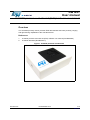
Figure 2. Premium EVK isometric view
By default the premium EVK is configured to operate using the USB port to a standard PC.
The software with the premium EVK demonstrates the basic proximity, ranging and light
sensing capabilities of the VL6180X sensor. Internally an STM32 acts as a USB to I2C
bridge allowing the PC to communicate with the sensor.
By reconfiguring a bank of switches, the STM32 is bypassed and the customer interface
port is enabled, allowing any suitable host to communicate with the sensor. This is shown in
Table 1.
DocID024985 Rev 5
3/18
16
Introduction
UM1651
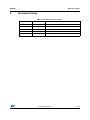
Table 1. Switch settings
Switch
Description
Default
SW3
SW4
SW5
Off: Customer host mode
On: USB / STM32 mode
SW6
SW7
4/18
DocID024985 Rev 5
On
UM1651
2
Premium EVK contents
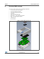
Premium EVK contents
The premium EVK is made up from the following components:
•
box base with rubber feet and pillars
•
box lid with clipping mechanism
•
PCB1480B screwed onto box base
•
PCB1453C
•
glass holder with foam insert
•
glass spacer – seven different thicknesses
•
glass – four identical glass samples
•
Calibration tool
•
Min USB cable
Figure 3. Premium EVK exploded view
DocID024985 Rev 5
5/18
16
Hardware
UM1651
3
Hardware
3.1
Calibration tool
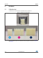
A calibration tool is delivered with the VL6180X premium evaluation kit
Figure 4. Calibration tool description
The way the different parts of the calibration tool are put together is describes in Figure 5
and Figure 6.
6/18
DocID024985 Rev 5
UM1651
Hardware
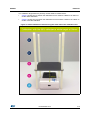
The calibration target allows to perfectly set the distance measurement.
•
Figure 5 shows how to position the calibration tool to measure a distance of 50mm to
do the offset calibration
•
Figure 6 shows how to position the calibration tool to measure a distance of 100mm to
do the cross-talk calibration
Figure 5. Offset calibration to 50 mm using the white side of the calibration tool
DocID024985 Rev 5
7/18
16
Hardware
UM1651
Figure 6. Cross-talk calibration to 100 mm using the black side of the calibration tool
8/18
DocID024985 Rev 5
UM1651
Hardware
3.2
PCB
3.2.1
Customer interface port (J3)
This port enables the end user to interface to the VL6180X sensor using a suitable host. The
only signals required to communicate with the sensors are I2C, power and ground. The
GPIO pins can be used as interrupts.
The header is compatible with the Aardvark I2C interface kit from Total Phase.
Figure 7. Customer interface port (J3)
2
10
1
9
Table 2 describes the pin outs of the customer interface port.
Table 2. Customer interface port (J3)
Pin number
3.2.2
Signal name
Description
Notes
1
SCL
PC clock line
2
GND
Ground
3
SDA
PC data line
4
5V0
5 volt supply
Provides board power
5
GPIO[0]
VL6180X GPIO
By default, configured as RESETn (active
low reset)
6
NC
Not connected
7
GPIO[1]
VL6180X GPIO
8
2V8_MICRO_EN
Enable signal
9
2V8_SENSOR_EN Enable signal
10
GND
Enables 2V8 regulator for STM32
Enables 2V8 regulator for VL6180X
Ground
JTAG header (J4)
This port is for programing the STM32. STMicroelectonics do not anticipate that this port will
be used by the end user, but the signals are described here for information.
This header is compatible with the RLink debugger programmer from Raisonance.
DocID024985 Rev 5
9/18
16
Hardware
UM1651
Figure 8. JTAG header (J4)
2
20
1
19
Table 3 describes the pin outs for the JTAG header.
Table 3. JTAG header (J4)
Pin number
Signal name
1
2V8_MICRO
Target voltage
2
2V8_MICRO
Target voltage
3
JTAG_RESET_N_MISO
Reset
4
GND
Ground
5
TDI
JTAG signal
6
GND
Ground
7
TMS
JTAG signal
8
GND
Ground
9
TCK
JTAG signal
10
GND
Ground
11
12
GND
Ground
13
TDO
JTAG signal
14
GND
Ground
15
RST_N
Reset
16
GND
Ground
18
Not used
GND
19
20
Notes
Not used
17
3.2.3
Description
Ground
Not used
GND
Ground
Debug header (J6)
The debug header permits easy interrogation of the I2C and GPIO signals.
Although not currently implemented, the header permits the debug of the GPIO signals from
up to four VL6180Xs connected through the two main connectors J1 and J2.
10/18
DocID024985 Rev 5
UM1651
Note:
Hardware
At the time of writing, no plug-in board with multiple sensors exists.
Figure 9. Debug header (J6) on underside of board
2
16
1
15
Table 4 describes the pin outs for the debug header.
Table 4. Debug header
Pin number
Signal name
Description
1
Not connected
2
Not connected
Notes
3
SCL
PC clock
4
SDA
PC data
5
GPIO[0]
VL6180X GPIO
6
GPIO[1]
VL6180X GPIO
7
GPIO_B[0]
Second VL6180X GPIO
For possible future expansion. Not
currently implemented.
8
GPIO_B[1]
Second VL6180X GPIO
For possible future expansion. Not
currently implemented.
9
GPIO_C[0]
Third VL6180X GPIO
For possible future expansion. Not
currently implemented.
10
GPIO_C[1]
Third VL6180X GPIO
For possible future expansion. Not
currently implemented.
11
GPIO_D[0]
Fourth VL6180X GPIO
For possible future expansion. Not
currently implemented.
12
GPIO_D[1]
Fourth VL6180X GPIO
For possible future expansion. Not
currently implemented.
13
ATEST1
Analog test signal
DocID024985 Rev 5
By default, configured as RESETn
11/18
16
Hardware
UM1651
Table 4. Debug header (continued)
Pin number
3.3
Signal name
Description
14
ATEST2
Analog test signal
15
CPOBS
Analog test signal
16
GND
Ground
Notes
Reset buttons
There are two reset buttons on the premium EVK: Micro RST and Sensor RST.
3.4
•
Micro RST. This is connected to the STM32 reset line and resets the STM32 to power
on state.
•
Sensor RST: This is connected to the two 2V8 voltage regulators that supply the
VL6180X sensor. Pressing this button performs a complete power down reset of the
VL6180X.
Glass and spacers
There are seven thicknesses of spacer supplied in the kit: 0.1, 0.3, 0.5, 1.0, 1.6, 2.0 and
2.4 mm.
The glass and spacer are held in place with a foam strip. It may be necessary to glue the
thinner spacers to the glass to provide mechanical rigidity as the thinner spacers are quite
flexible.
The glass supplied is as per drawing EL00462 (see Figure 10). The interaction between the
IR aperture in the glass, the viewing cones of the sensor and the air gap between the sensor
and glass is important. Experimenting with the air gap or building new glass samples will
affect the performance of the sensor.
12/18
DocID024985 Rev 5
DocID024985 Rev 5
)
(
'
&
%
/LQHDU
3ODFH'HFLPDOV
3ODFH'HFLPDOV
3ODFH'HFLPDOV
$QJXODUGHJUHHV
'LDPHWHU 3RVLWLRQ
6XUIDFH)LQLVKPLFURQV
7ROHUDQFHVXQOHVVRWKHUZLVHVWDWHG
'(7&7,21
&(175(
7KLVGUDZLQJLVWKHSURSHUW\RI670LFURHOHFWURQLFV )LQLVK
DQGZLOOQRWEHFRSLHGRUORDQHGZLWKRXWWKH
6((127(6
ZULWWHQSHUPLVVLRQRI670LFURHOHFWURQLFV
3/$,1*/$66PP7+,&.
%/$&.3$,17('6,'(2)&29(5
$OOGLPHQVLRQVLQPP
9/9,(:,1*:,1'2:
,535,17,1*7275$160,66,21
%(7:((1$1'QP$1'!
$%29(QP
,QWHUSUHWGUDZLQJSHU%65'$QJOH3URMHFWLRQ 0DWHULDO
$
),567,668(
$
(/
3DUW1R
2&7
'DWH
'UDZQ
0
$OOGLPHQVLRQV
'$7(
6FDOH
(
'
&
%
$
'R1RW6FDOH
LQPP
)
670LFURHOHFWURQLFV
,PDJLQJ'LYLVLRQ
7LWOH VL6180X glass with 6KHHW
(9.9/*/$66:,7+
2)
29$/$3(5785(
oval aperture
9,(:21723$,17('6,'(
'(6&5,37,21
5(9
UM1651
Hardware
Figure 10. Glass supplied with VL6180X premium EVK
13/18
16
5
4
3
2
EXT_GPIO[1]
2V8
ATEST2
14
16
13
15
CPOBS
ATEST2
ATEST1
R
HV
15
16
16
Sensor plug-in headers
14
15
13
13
14
12
8
8
12
7
7
11
6
6
11
5
5
10
4
4
9
3
3
9
2
2
10
1
1
GPIO[1]
GPIO[0]
GPIO_D[1]
GPIO_D[0]
GPIO_C[1]
GPIO_C[0]
GPIO_B[1]
GPIO_B[0]
SDA
SCL
2V8
RST_N
TDO
TCK
TMS
TDI
JTAG_RESET_N_MISO
GND
0R
R15
PD9
2V8_MICRO
2V8_MICRO_EN
2V8_MICRO
R30
A
B
10K
10K
BC817-16
Q6
R33
10K
STMicroelectronics - Imaging Division CONFIDENTIAL
5V0
J2
GPIO_D[1]
12
11
J1
GPIO_C[1]
10
Test header
GPIO_B[1]
8
GPIO[1]
SDA
9
2V8_VCSEL
CPOBS
ATEST1
GPIO_D[0]
GPIO_C[0]
9
7
6
5
2
GPIO[0]
GPIO_B[0]
8
10
7
(compatible with Aardvark)
4
J6
6
5
Customer interface
EXT_2V8_SENSOR_EN
3
1
EXT_SDA
EXT_GPIO[0]
SCL
0_4IN
4
R17
2
NF
3
R16
1
R28
NF
EXT_SCL
R29
2
R32
R31
5V0
2V8_MICRO
14
16
18
20
13
15
17
19
C
*7)
&34+-.5)!&6
USB_DP
USB_DN
5V0
D
5V0
D
)*+,-.
Standard STM32 USB interface
22R
R12
22R
R11
SW1
Sesnor Reset
2V8_SENSOR_EN
12
8
10
9
11
7
6
5
2
4
J4
3
1
2V8_MICRO
Rlink STM32 Programming header
BC817-16
Q7
2V8_MICRO
R34
1
JP4
5V0
10K
J3
R35
GND1
10K
10K
C
10K
B
10K
R10
E
2V8_SENSOR_EN
2V8_MICRO_EN
100NF
10UF
$%
&
...
+01.21/.+,
+,
2+
IO2 3
IO1 1
GND 2
C10
C11
5V0
2V8_SENSOR_EN
USBLC6-2SC6
6 IO_1
5
VBUS
4 IO_2
U11
1UF
C7
1UF
C4
1UF
C3
GND
9
U1
NC
VO
GND
9
U2
NC
VO
CS
VI
U3
NC
VO
GND
NC
DATA+
DATA-
E
'(
2
2V8
JP1
"# /
7 6
2
2V8_VCSEL
2
2V8_MICRO
JP3
JP2
TYPE_B
VCC
J5
4.7UF
C9
1
!! +
5
4
3
2
1
1
4.7UF
C6
1
4.7UF
C2
GND
9
XC6210B282MR
CS
VI
XC6210B282MR
CS
VI
XC6210B282MR
Seperate 2v8 supplies with current measurement
R5
R1
R2
1
2
1
10K
R9
DocID024985 Rev 5
47K
5
4
3
2
1
VL6180X premium EVK board schematic
R8
3.5.1
39K
Schematics
R7
3.5
1k5
10K
10K
10K
14/18
SHELL1
SHELL2
A
Hardware
UM1651
Figure 11. VL6180X premium EVK board schematic (page 1/2)
5
4
3
2
2V8_MICRO
1M
R
2V8_MICRO
1UF
C18
R18
33PF
C20
RST_N
10K
R14
54 PB15
52 PB13
53 PB14
48 PB11
51 PB12
95 PB8
96 PB9
47 PB10
92 PB6
93 PB7
90 PB4
91 PB5
37 PB2
89 PB3
35 PB0
36 PB1
77 PA15
72 PA13
76 PA14
69 PA10
70 PA11
71 PA12
67 PA8
68 PA9
31 PA6
32 PA7
29 PA4
30 PA5
25 PA2
26 PA3
23 PA0-WKUP
24 PA1
73 NC
94 BOOT0
21 VREF+
20 VREF-
14 NRST
13 OSC_OUT
12 OSC_IN
6
VBAT
U9
LQFP100
STM32F103VET6
A
B
STMicroelectronics - Imaging Division CONFIDENTIAL
GPIO_D[1]
GPIO_C[1]
GPIO_B[1]
STM32_GPIO[1]
STM32_SDA
STM32_SCL
JTAG_RESET_N_MISO
TDO
TDI
TCK
TMS
USB_DP
USB_DN
GPIO_D[0]
GPIO_C[0]
GPIO_B[0]
STM32_GPIO[0]
STM32 Reset
SW2
0R
R20
8MHz
10UF
100NF
PC10 78
PC11 79
PC8 65
PC9 66
PC6 63
PC7 64
PC4 33
PC5 34
PC2 17
PC3 18
PC0 15
PC1 16
C12
C13
PE14 45
PE15 46
PE12 43
PE13 44
PE10 41
PE11 42
PE8 39
PE9 40
PE6 5
PE7 38
PE4 3
PE5 4
PE2 1
PE3 2
PE0 97
PE1 98
PD14 61
PD15 62
PD12 59
PD13 60
PD10 57
PD11 58
PD8 55
PD9 56
PD6 87
PD7 88
PD4 85
PD5 86
PD2 83
PD3 84
PD0 81
PD1 82
PC15-PSC32_OUT 9
PC12 80
PC13-TAMPER-RTC 7
PC14-OSC32_IN 8
C
C
(/73!
&34+-.5)!&6
VSS_1
49
R22
VSS_2
74
X1
47R
VSS_3
99
22
2V8_MICRO
VSS_4
33PF
1k5
50
VDD_1
VSS_5
R21
75
VDD_2
27
C19
R19
100
VDD_3
10
1K
28
VDD_4
19
VDDA
1
1k5
11
VDD_5
VSSA
USB_ENUM
PD9
120R
I2C_COMMS
R3
2V8_MICRO
GPIO[1]
GPIO[0]
I2C_COMMS
USB_ENUM
2V8_MICRO
100NF
100NF
D
)*+,-.
C30
C29
D1
D2
EXT_2V8_SENSOR_EN
STM32_SDA
EXT_SDA
STM32_SCL
EXT_SCL
STM32_GPIO[1]
EXT_GPIO[1]
STM32_GPIO[0]
$%
Q3
1
2
100NF
C35
&
...
+01.21/.+,
+,
2+
100NF
C31
D3
D4
Q4
1
2
5V0
0R
R6
LED enable
2v drop @ 5mA
E
'(
!! /
GND
10UF
"# /
10UF
C33
2V8_SENSOR_EN
SDA
SCL
GPIO[1]
GPIO[0]
E
2V8_MICRO
420R
C34
5mA through each LED
EXT_GPIO[0]
Q2
1
2
420R
STM32_2V8_SENSOR_EN
Q1
1
420R
100NF
R36
2
R24
C32
STM32 decoupling
STM32_2V8_SENSOR_EN
GND for JTAG
DFU_BOOTLOADER
10UH
D
R4
L1
2V8_MICRO
420R
SW7
SW6
SW5
SW4
SW3
R13
B
LK1
R23
2
2
3
1
3
1
3
1
3
1
3
2
2
2
DocID024985 Rev 5
1
A
5
4
3
2
1
UM1651
Hardware
Figure 12. VL6180X premium EVK board schematic (page 2/2)
15/18
16
DocID024985 Rev 5
5
4
3
R
C3
4.7UF
AVDD
4.7UF
C4
HV
ATEST2
ATEST1
47K
R1
6
5
4
3
2
1
SDA
SCL
GPIO0
ATEST2
ATEST1
GPIO1
A
B
This drawing is the property of STMicroelectronics and must not be copied or
reproduced in any way without the written permission of STMicroelectronics
Sheet Name:
STMicroelectronics - Imaging Division Design Name:
CONFIDENTIAL
AVDD_VCSEL
AVDD
SDA
SCL
GPIO0
ATEST2
ATEST1
GPIO1
B
R2
16/18
47K
C
Schematic
VL6180X Premium EVK Sensor Plug-in
16
14
15
13
14
16
12
13
15
11
8
8
12
7
7
10
6
6
9
5
5
11
4
4
9
3
3
10
2
100NF
100NF
J2
C1
C2
1
J1
7
8
9
10
11
12
2
HV
AVDD_VCSEL
AVSS_VCSEL
AVDD
NC
GND
1
U1
VL6180X
C
Dwg. No:
Drawn By:
HV
AVDD_VCSEL
AVDD
D
PCB1453
DCH
GPIO1
GPIO0
SDA
SCL
D
Rev:
Date:
C
Ver:
000
19/05/2014:16:38
E
Sheet Size:
A3
SHEET 1
E
OF 1
5
4
3
2
1
3.5.2
2
1
A
Hardware
UM1651
VL6180X module plug-in board
Figure 13. VL6180X module plug-in board
UM1651
4
Revision history
Revision history
Table 5. Document revision history
Date
Revision
Changes
25-Oct-2013
1
Initial release.
15-May-2014
2
Change document title
16-May-2014
3
Correct typo error
10-Jun-2014
4
Change document properties
01-Oct-2014
5
Update Disclaimer
DocID024985 Rev 5
17/18
17
UM1651
IMPORTANT NOTICE – PLEASE READ CAREFULLY
STMicroelectronics NV and its subsidiaries (“ST”) reserve the right to make changes, corrections, enhancements, modifications, and
improvements to ST products and/or to this document at any time without notice. Purchasers should obtain the latest relevant information on
ST products before placing orders. ST products are sold pursuant to ST’s terms and conditions of sale in place at the time of order
acknowledgement.
Purchasers are solely responsible for the choice, selection, and use of ST products and ST assumes no liability for application assistance or
the design of Purchasers’ products.
No license, express or implied, to any intellectual property right is granted by ST herein.
Resale of ST products with provisions different from the information set forth herein shall void any warranty granted by ST for such product.
ST and the ST logo are trademarks of ST. All other product or service names are the property of their respective owners.
Information in this document supersedes and replaces information previously supplied in any prior versions of this document.
© 2014 STMicroelectronics – All rights reserved
18/18
DocID024985 Rev 5