1
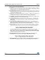
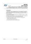
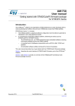
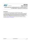
UM1876
User manual
Getting started with VL6180X proximity, gesture, ambient light
sensor software expansion for STM32Cube
Introduction
STMicroelectronics has introduced various evaluation and development tools to facilitate
the integration of the VL6180X sensor in customer’s applications.
The VL6180X is a time-of-flight 3-in-1 proximity, gesture and ALS sensor, based on ST
patented FlightSense™ technology.
This document provides detailed firmware installation guidelines for:
•
Standalone operation
•
PC graphical user interface (GUI)
•
Application programming interface (API) for the use of VL6180X sensor.
The following list of evaluation devices are available:
•
Two Nucleo packs:
–
The P-NUCLEO-6180X1: Includes STM32F401RE Nucleo and
X-NUCLEO-6180XA1 expansion boards
–
The P-NUCLEO-6180X2: Includes STM32L053R8 Nucleo and
X-NUCLEO-6180XA1 expansion boards
•
The X-NUCLEO-6180XA1 expansion board, this board can be used with all STM32
nucleo boards.
•
The VL6180X-SATEL: Includes two VL6180X satellite boards. Up to three VL6180X
satellite boards can be connected on the X-NUCLEO-6180XA1 expansion board.
Figure 1. P-NUCLEO-6180X1 Nucleo pack
With VL6180X satellites
Table 1. Ordering information
Ordering code
November 2015
Description
P-NUCLEO-6180X1
X-NUCLEO-6180XA1 and STM32F401RE Nucleo boards
P-NUCLEO-6180X2
X-NUCLEO-6180XA1 and STM32L053R8 Nucleo boards
X-NUCLEO-6180XA1
VL6180X expansion board for STM32 Nucleo board family
VL6180X-SATEL
Two VL6180X satellite boards
DocID027648 Rev 3
1/57
www.st.com
57
Contents
UM1876
Contents
1
Introduction . . . . . . . . . . . . . . . . . . . . . . . . . . . . . . . . . . . . . . . . . . . . . . . . 4
1.1
Document references . . . . . . . . . . . . . . . . . . . . . . . . . . . . . . . . . . . . . . . . . 4
1.2
Hardware description . . . . . . . . . . . . . . . . . . . . . . . . . . . . . . . . . . . . . . . . . 4
2
What is STM32Cube? . . . . . . . . . . . . . . . . . . . . . . . . . . . . . . . . . . . . . . . . 5
3
How does this software complement STM32Cube? . . . . . . . . . . . . . . . 5
4
VL6180X Nucleo pack software installation . . . . . . . . . . . . . . . . . . . . . . 6
4.1
5
6
STM32 Nucleo board software suite installation . . . . . . . . . . . . . . . . . . . . 6
4.1.1
STSW-LINK009: STM32 Nucleo board Windows USB driver installation 6
4.1.2
STSW-LINK007: STM32 Nucleo board PC communication driver . . . . . 8
VL6180X standalone demonstrations . . . . . . . . . . . . . . . . . . . . . . . . . . . 9
5.1
Installation of the VL6180X standalone operation . . . . . . . . . . . . . . . . . . . 9
5.2
“RangingAndALS” demonstration . . . . . . . . . . . . . . . . . . . . . . . . . . . . . . . 13
5.2.1
Ranging mode . . . . . . . . . . . . . . . . . . . . . . . . . . . . . . . . . . . . . . . . . . . . 13
5.2.2
ALS mode . . . . . . . . . . . . . . . . . . . . . . . . . . . . . . . . . . . . . . . . . . . . . . . 19
5.3
“RangingWithSatellites” demonstration . . . . . . . . . . . . . . . . . . . . . . . . . . 20
5.4
“GestureDetect1” demonstration . . . . . . . . . . . . . . . . . . . . . . . . . . . . . . . 22
5.4.1
Ranging mode and single swipe / single tap (TAP_SWIPE_2) mode . . 25
5.4.2
Single directional swipe (DIRSWIPE_1) mode . . . . . . . . . . . . . . . . . . . 26
VL6180X software graphical user interface (GUI) . . . . . . . . . . . . . . . . 29
6.1
Installation of the VL6180X PC software graphical user interface (GUI) . 29
6.2
Ranging tab . . . . . . . . . . . . . . . . . . . . . . . . . . . . . . . . . . . . . . . . . . . . . . . 32
6.3
6.2.1
Signal strength (power) graph . . . . . . . . . . . . . . . . . . . . . . . . . . . . . . . . 34
6.2.2
Actual distance (ToF) graph . . . . . . . . . . . . . . . . . . . . . . . . . . . . . . . . . . 36
6.2.3
Actual distance (ToF) graph showing thresholds . . . . . . . . . . . . . . . . . . 38
6.2.4
Gesture help . . . . . . . . . . . . . . . . . . . . . . . . . . . . . . . . . . . . . . . . . . . . . 39
6.2.5
Dmax . . . . . . . . . . . . . . . . . . . . . . . . . . . . . . . . . . . . . . . . . . . . . . . . . . . 40
6.2.6
High speed . . . . . . . . . . . . . . . . . . . . . . . . . . . . . . . . . . . . . . . . . . . . . . . 40
Calibration tab . . . . . . . . . . . . . . . . . . . . . . . . . . . . . . . . . . . . . . . . . . . . . 40
6.3.1
2/57
Offset calibration procedure with P-NUCLEO-6180X(i) . . . . . . . . . . . . . 40
DocID027648 Rev 3
UM1876
Contents
6.3.2
VL6180X offset and cross-talk calibration in a final product . . . . . . . . . 43
6.4
Ambient light sensor (ALS) tab . . . . . . . . . . . . . . . . . . . . . . . . . . . . . . . . . 46
6.5
Options tab . . . . . . . . . . . . . . . . . . . . . . . . . . . . . . . . . . . . . . . . . . . . . . . . 48
6.5.1
Data Logs options window . . . . . . . . . . . . . . . . . . . . . . . . . . . . . . . . . . . 48
6.5.2
Help window . . . . . . . . . . . . . . . . . . . . . . . . . . . . . . . . . . . . . . . . . . . . . 49
6.5.3
About window . . . . . . . . . . . . . . . . . . . . . . . . . . . . . . . . . . . . . . . . . . . . 49
6.6
Data log file . . . . . . . . . . . . . . . . . . . . . . . . . . . . . . . . . . . . . . . . . . . . . . . 51
6.7
I2C log file . . . . . . . . . . . . . . . . . . . . . . . . . . . . . . . . . . . . . . . . . . . . . . . . . 53
7
Application programming interface (API) . . . . . . . . . . . . . . . . . . . . . . . 54
8
Revision history . . . . . . . . . . . . . . . . . . . . . . . . . . . . . . . . . . . . . . . . . . . 56
DocID027648 Rev 3
3/57
57
Introduction
UM1876
1
Introduction
Note:
In this document P-NUCLEO-6180X(i) stand for P-NUCLEO-6180X1 and
P-NUCLEO-6180X2.
1.1
Document references
Table 2. Document references
Description
1.2
DocID
Datasheet - VL6180X proximity and ambient light sensing (ALS) module
DocID026171
Data brief - Proximity, gesture, ambient light sensor expansion board
based on VL6180X for STM32F401RE
DocID027616
Data brief - Proximity, gesture, ambient light sensor expansion board
based on VL6180X for STM32L053R8
DocID027625
Data brief - Proximity and ambient light sensor expansion board based on
VL6180X for STM32 Nucleo
DocID027252
Data brief - P-NUCLEO-6180X1 and P-NUCLEO-6180X2 packs PC
graphical user interface (GUI)
DocID027684
Data brief - Proximity, gesture, ambient light sensor software expansion
for STM32Cube
DocID027687
Data-brief - VL6180X application programing interface (API)
DocID027370
Data-brief - VL6180X satellite boards compatible with VL6180X boards
DocID027253
Hardware description
The X-NUCLEO-6180XA1 expansion board:
•
Is compatible with ArduinoTM UNO R3 connectors.
•
Must be plugged into an STM32 Nucleo board.
•
Can be superposed with all ST expansion boards, which allows, for example, to
develop VL6180X applications with Bluetooth or Wifi interface.
The STM32 Nucleo board is connected to the PC via a mini USB connector.
4/57
DocID027648 Rev 3
UM1876
2
What is STM32Cube?
What is STM32Cube?
STMCubeTM represents an original initiative by STMicroelectronics to ease developers' life
by reducing development effort, time and cost. STM32Cube covers the STM32 portfolio.
Version 1.x of STM32Cube includes:
3
•
STM32CubeMX, a graphical software configuration tool that allows the generation of C
initialization code using graphical wizards
•
A comprehensive embedded software platform, delivered per series (such as the
STM32CubeF4 for STM32F4 series)
•
STM32Cube HAL, an STM32 abstraction layer embedded software, ensuring
maximized portability across the STM32 portfolio
–
A consistent set of middleware components, such as RTOS, USB, TCP/IP,
graphics
–
All embedded software utilities, including a full set of examples
How does this software complement STM32Cube?
The proposed software is based on the STM32CubeHAL, the hardware abstraction layer for
the STM32 microcontroller. The package extends STM32Cube by providing a Board
Support Package (BSP) for the X-NUCLEO-6180X expansion board and a VL6180X API
component (in Drivers\BSP\Components\vl6180x directory) to program, control and get
ranging/ALS values from the VL6180X device.
Several example projects are included in the Projects\Multi\Examples\VL6180X directory, the
developer can use these examples to start experimenting with the code. These examples
are ready to be compiled using Keil (MDK-ARM), IAR (EWARM) or STM32 Workbench
(SW4STM32):
•
•
RangingAndALS example features
–
Ranging or ALS modes
–
Selectable scaling in ranging mode
–
Interrupt mode in ranging mode
–
Ranging and ALS measures displayed on 7-segment display
RangingWithSatellites example features
–
Simultaneous ranging from main VL6180X plus up to 3 satellites
Ranging measures displayed on 7-segment display.
One example project is included in Projects\Multi\Applications directory:
•
GestureDetect1 example feature
–
Ranging mode
–
Single swipe and single tap detection with on board VL6180X
–
Directional swipes detection with two VL6180X satellites
DocID027648 Rev 3
5/57
57
VL6180X Nucleo pack software installation
4
UM1876
VL6180X Nucleo pack software installation
ST delivers a software suite allowing the user to discover, through standalone
demonstrations and a PC graphical user interface (GUI), the VL6180X ranging and ambient
light sensing (ALS) features.
4.1
STM32 Nucleo board software suite installation
The Nucleo board software suite is available from www.st.com, this software is compatible
with all STM32 Nucleo boards.
This installation software suite consists of:
4.1.1
•
STSW-LINK009, ST-Link, ST-Link/V2, ST-Link/V2-1 USB driver signed for XP,
Windows7 and 8. This driver must be first installed.
•
STSW-LINK007, ST-Link/V2-1 firmware update.
When STSW-LINK009 and STSW-LINK007 firmware are installed the STM32 Nucleo
board is configured and ready to use with a PC.
STSW-LINK009: STM32 Nucleo board Windows USB driver installation
•
On www.st.com home page search for “STSW-LINK009”
Figure 2. STM32 Nucleo board Windows USB driver installation - step 1
•
On next page click on “STSW-LINK009”
Figure 3. STM32 Nucleo board Windows USB driver installation - step 2
•
6/57
On next page click on “Download”
DocID027648 Rev 3
UM1876
VL6180X Nucleo pack software installation
Figure 4. STM32 Nucleo board Windows USB driver installation - step 3
•
From stsw-link009.zip, unpack the .zip file and run stlink_winusb_install.bat. This will
install the necessary USB drivers to allow communications between the Nucleo board
and the PC.
Figure 5. STM32 Nucleo board Windows USB driver installation - step 4
•
Plug a USB cable between the PC and STM32 Nucleo board. Allow the board driver
installations to complete before proceeding.
DocID027648 Rev 3
7/57
57
VL6180X Nucleo pack software installation
4.1.2
UM1876
STSW-LINK007: STM32 Nucleo board PC communication driver
•
To install STSW-LINK007 repeat the steps 1 to 3 performed for the installation of the
STSW-LINK009 STM32 Nucleo board Windows USB driver installation.
•
Unpack the downloaded stsw-link007.zip file and run STLinkUpgrade.exe.
•
Ensure the Nucleo board is connected via the USB port.
•
Click 'device connect' on the dialogue and confirm the board has successfully
connected.
•
When prompted to upgrade to the latest version check that the suggested version is
later than the current firmware version then, click 'YES’ to proceed.
Figure 6. STM32 Nucleo board communication driver with PC installation - step 4
3
2
1
8/57
DocID027648 Rev 3
UM1876
VL6180X standalone demonstrations
5
VL6180X standalone demonstrations
5.1
Installation of the VL6180X standalone operation
Note:
If not already done, plug VL6180X expansion board on to STM32 Nucleo board
To install VL6180X standalone demonstrations.
•
In P-NUCLEO-6180X1 or in P-NUCLEO-6180X2 web pages select
X-CUBE-6180XA1.
Figure 7. VL6180X standalone demonstration installation - step 1
•
Click on “Download” then save it
Figure 8. VL6180X standalone demonstration installation - step 2
•
Unzip the file
•
The standalone demonstration software are located in the directory:
Nucleo/Projects/Multi/Examples/VL6180X (see Figure 9).
DocID027648 Rev 3
9/57
57
VL6180X standalone demonstrations
UM1876
Figure 9. Demonstration binary files location(a)
670&XEH([SDQVLRQB9/;B9[\]
3URMHFWV
0XOWL
$SSOLFDWLRQV
9/;
*HVWXUH'HWHFW
%LQDU\
*HVWXUH'HWHFWB1XFOHR)ELQ
([DPSOHV
9/;
5DQJLQJ$QG$/6
%LQDU\
5DQJLQJ$QG$/6B1XFOHR)ELQ
5DQJLQJ$QG$/6B1XFOHR/ELQ
5DQJLQJ$QG$/6B1XFOHR/ELQ
5DQJLQJ:LWK6DWHOOLWHV
%LQDU\
5DQJLQJ:LWK6DWHOOLWHVB1XFOHR)ELQ
5DQJLQJ:LWK6DWHOOLWHVB1XFOHR/ELQ
5DQJLQJ:LWK6DWHOOLWHVB1XFOHR/ELQ
•
Each example code (RangingAndALS and RangingWithSatellites) can be compiled
using one of the provided projects (MDK-ARM, EWARM, SW4STM32) for each Nucleo
board type: L476, F401 and L053.
•
Pre-compiled binaries are also provided in the Bin directories of each example.
–
For the L053R8, RangingAndALS_NucleoL053.bin and
RangingWithSatellites_NucleoL053.bin.
–
For the F401RE, RangingAndALS_NucleoF401.bin and
RangingWithSatellites_NucleoF401.bin.
–
For the L476RG, RangingAndALS_NucleoL476.bin and
RangingWithSatellites_NucleoL476.bin.
•
RangingAndALS_NucleoXXXX.bin shows the behavior of a single VL6180X in ranging
and ALS modes (see Section 5.2: “RangingAndALS” demonstration).
•
RangingWith Satellites_NucleoXXXX.bin.bin shows the behavior of four VL6180X in
ranging mode (see Section 5.3: “RangingWithSatellites” demonstration).
a. The list above shows the examples available in the latest version of the
STM32CubeExpansion_VL6180X_Vx.y.z. More examples can be added.
10/57
DocID027648 Rev 3
UM1876
VL6180X standalone demonstrations
•
The example code GestureDetect1 can be compiled using one of the provided projects
(MDK-ARM, EWARM, SW4STM32).
•
A pre-compiled binary is also provided in the Binary directory for this example.
–
GestureDetect1_NucleoF401.bin.
Drag and drop the “.bin” file you want to select to the L053R8 or F401RE or L476RG STM32
Nucleo board.
Figure 10. VL6180X standalone demonstration installation - step 4
Drag and drop
DocID027648 Rev 3
YYYYYYY_NucleoXXXX.bin
11/57
57
VL6180X standalone demonstrations
UM1876
Press the black reset button on the STM32 Nucleo board and release it,
the Nucleo pack is now running in “standalone” mode, meaning no PC is required to control
the Nucleo pack, USB connection is only used to power the Nucleo pack.
The switch SW1 can be asserted during any stage of operation.
•
When running in Standalone mode, the SW1 switch on the VL6180X expansion board
selects the value displayed on the 4-digit display, see Figure 11.
–
If switched to “Range”, the distance detected between VL6180X and the nearest
object is displayed in mm.
–
If switched to “ALS”, the ambient light level is displayed in Lux.
Figure 11. Value displayed versus SW1 switch setting
•
Move your hand or any object in front of VL6180X and read the value displayed on the
4-digit display.
The VL6180X Nucleo pack provides various demonstration modes for ranging and ambient
light sensing:
•
Scale Factor Modes (1,2 and 3), to demonstrate the extended ranging performance of
the device, with the scale factors applied manually in isolation or automatically.
•
Alarm threshold modes, to demonstrate alarm conditions, with the VL6180X sending
an interrupt to the application host as range measurements cross pre-defined range
threshold limits. The benefit of this interrupt mode is that the host can stay in stand-by
mode, reducing power consumption of the system, and the VL6180X will automatically
send an interrupt to the host when the thresholds are reached.
•
ALS mode, demonstrating the Ambient Light Sensor performance.
•
Multiple VL6180X device operation.
These are described in more detail in the following sub-sections.
12/57
DocID027648 Rev 3
UM1876
5.2
VL6180X standalone demonstrations
“RangingAndALS” demonstration
•
Drag and drop the “RangingAndALS_NucleoXXXX.bin” file, which one will depend on
whether you use a L053R8 or a F401RE or a L476RG STM32 Nucleo board.
Figure 12. VL6180X standalone RangingAndALS installation - step 4
Drag and drop
5.2.1
RangingAndALS_NucleoXXXX.bin
Ranging mode
The switch SW1 must be in “RANGE” mode:
In this ranging mode the left digit displays “r”, see Figure 13, during the ranging
measurement.
Figure 13. Left display digit in ranging mode
DocID027648 Rev 3
13/57
57
VL6180X standalone demonstrations
UM1876
When the USB cable is plugged in the message “SF 1” is displayed for a few seconds (see
Figure 14). This message indicates that VL6180X scaler factor is set to 1. Consequently
range measurements between the VL6180X and the target are confined to the limits 0 and
20cm with a granularity of 1mm.
Figure 14. SF 1 message
There are two different types of modes available under RangingAndALS.
•
A short press on the STM32 Nucleo board blue button will activate the Scale Factor
mode.
•
A long press on the STM32 Nucleo board blue button will activate the Alarm threshold
mode
After the first short press on the blue button of the STM32 Nucleo board,
,
the message “SF 2” is displayed for a few seconds (see Figure 15); This message indicates
that VL6180X scaler factor is set to 2. Consequently range measurements between the
VL6180X and the target are confined to the limits 0 and 40cm with a granularity of 2mm.
Figure 15. SF 2 message
At next short press on the blue button of the STM32 Nucleo board,
,
the message “SF 3” is displayed for a few seconds (see Figure 16). This message indicates
that VL6180X scaler factor is set to 3. Consequently range measurements between the
VL6180X and the target are confined to the limits 0 and 60cm with a granularity of 3mm.
Figure 16. SF 3 message
14/57
DocID027648 Rev 3
UM1876
VL6180X standalone demonstrations
At next short press on the blue button of the STM32 Nucleo board,
,
the message “SF A” is displayed for a few seconds (see Figure 17). This message indicates
that VL6180X scaler factor is set to automatic mode, resulting in range measurements
between the VL6180X and the target being confined to the limits 0 to 60cm with a
granularity of:
•
1mm for the range measurement between 0 and 20cm
•
2mm for the range measurement between 20 and 40cm
•
3mm for range measurement between 40 and 60cm
Figure 17. SF A message
Starting from a USB cable connection, the sequence linked to sequential short presses on
the blue button of the STM32 Nucleo board is described in Figure 18.
Figure 18. Range measurement sequence versus short presses on blue button
DocID027648 Rev 3
15/57
57
VL6180X standalone demonstrations
UM1876
At any time the user can perform a long press on the blue button of the STM32 Nucleo
board.
A long press on the blue button of the STM32 Nucleo board,
,
will activate the Alarm modes. For the duration of the button press the message “rb”
(Release Button) will be displayed (see Figure 19) to indicate that the button must be
released to proceed to the various alarm threshold modes provided.
Figure 19. rb message
When the blue button of the STM32 Nucleo board is released, the message “A-Lo” (“Alarm
Low”) is displayed during few seconds (see Figure 20) to indicate the transition to the low
range threshold mode.
This mode alerts the user to range measurements crossing below a pre-defined lower range
threshold, it is set for this demonstration mode at 10cm. In a real application use case, the
value of this threshold can be programmed through the VL6180X registers:
•
Range measurements of targets above the threshold will result in the message “L“ (see
Figure 21).
•
Range measurements of targets below the threshold will result in the message “L--- “ to
indicate the alarm state (see Figure 21).
Figure 20. A-Lo message
16/57
DocID027648 Rev 3
UM1876
VL6180X standalone demonstrations
Figure 21. L and L--- message
With the device in the “Alarm Low” mode, a subsequent short press
,
on the blue button of the STM32 Nucleo board will transition to the ‘Alarm High’ mode,
resulting in the message “A-hi” being displayed for a short duration (see Figure 22).
This mode alerts the user to range measurements transgressing above a pre-defined upper
range threshold, set for this demonstration mode at 25cm. In a real application use case, the
value of this threshold can be programmed through VL6180X registers:
•
Range measurements of targets above the threshold will result in the message “H“ (see
Figure 23)
•
Range measurements of targets above the threshold will result in the message “H--- “
to indicate the alarm state (see Figure 23).
Figure 22. A-hi message
DocID027648 Rev 3
17/57
57
VL6180X standalone demonstrations
UM1876
Figure 23. H and H--- message
With the device in the ‘Alarm High’ mode, a subsequent short press
,
on the blue button will transition to the ‘Dual Alarm’ mode, resulting in the message “A-Oo”
being displayed for a short duration (see Figure 24). Subsequently, moving targets may
trigger up to two lower and upper range measurement thresholds.
If the target is below the pre-defined lower threshold (10cm), or above the pre-defined upper
threshold (25cm),the message “O---“ will be displayed to indicate the alarm state (see
Figure 25).
Otherwise, if the target is within the upper and lower thresholds, the message “O“ is
displayed.
Figure 24. A-Oo message
18/57
DocID027648 Rev 3
UM1876
VL6180X standalone demonstrations
Figure 25. O and O--- message
At next short press on the blue button of the STM32 Nucleo board, the user will return to “ALo” use case
A subsequent long press on the blue button of the STM32 Nucleo board will exit the alarm
mode, the message “rb” is displayed for the duration of the press and, following release, the
mode will exit “Alarm” and return to Ranging “SF-1”.
5.2.2
ALS mode
The switch SW1 must be in “ALS” mode:
If the ambient light value is below 1000 Lux, the left digit of the display is as described in
Figure 26 and the three other digits give the Lux value.
Figure 26. Left digit of the display if ambient light value below 1000 Lux
If the ambient light value is above 1000 Lux, the left digit of the display is as described in
Figure 27 and the three other digits give the Lux value minus 1000 Lux. In this example the
lux value is 1348 lux.
DocID027648 Rev 3
19/57
57
VL6180X standalone demonstrations
UM1876
Figure 27. Left digit of the display if ambient light value above 1000 Lux
The VL6180X sensor is able to measure up to 10kLux, however this demonstration kit is
limited to 1.8kLux.
5.3
“RangingWithSatellites” demonstration
•
Drag and drop the “RangingWith Satellites_NucleoXXXX.bin” file, which one you select
will depend if you use a L053R8 or a F401RE or a L476RG STM32 Nucleo board.
Figure 28. VL6180X RangingWithSatellites demonstration installation - step 4
Drag and drop
RangingWithSatellites_NucleoXXXX.bin
Figure 29. STM32 Nucleo, VL6180X expansion and VL6180X satellites boards “RangingWithSatellites” configuration
20/57
DocID027648 Rev 3
UM1876
VL6180X standalone demonstrations
The multiple VL6180X standalone demonstration is only for ranging.
When the USB cable is connected, the display shows below letters (see Figure 30).
Figure 30. Letters displayed versus VL6180X satellite boards
9/;PDLQERDUGLQGLFDWRU
9/;ULJKWVDWHOOLWHLQGLFDWRU
9/;OHIWVDWHOOLWHLQGLFDWRU
9/;ERWWRPVDWHOOLWHLQGLFDWRU
Each digit letter indicates one of the four potential VL6180X devices in operation:
•
“t”: VL6180X on the main board
•
“L” VL6180X on the left satellite board
•
“b” VL6180X on the bottom satellite board
•
“r” VL6180X on the right satellite board
After a short press on the blue button of the STM32 Nucleo board,
,
horizontal bar segments are displayed on the LCD digits to indicate various ranging
distances. Each digit corresponds to one of up to four VL6180X devices attached, as
illustrated in Figure 31:
•
If the target is within short range of a VL6180X device, a single bar segment is
displayed on its digit.
•
When the target is in medium or long range of the VL6180x device, two and three bars
are displayed, respectively, on the corresponding digit.
Once the target exceeds a pre-defined maximum limit the corresponding digit for the
VL6180X device has an empty display.
DocID027648 Rev 3
21/57
57
VL6180X standalone demonstrations
UM1876
Figure 31. Bar-graph displayed versus the distance between the target and the 4
VL6180X devices
This demonstration can be used as a starting point for developing basic gesture recognition
algorithms using several VL6180X devices.
5.4
“GestureDetect1” demonstration
•
Drag and drop the “GestureDetect1_NucleoF401.bin” file, for this you have to use a
F401RE STM32 Nucleo board.
Figure 32. VL6180X GestureDetect1 demonstration installation - step 4
Drag and drop
22/57
DocID027648 Rev 3
GestureDetect1_NucleoF401.bin
UM1876
VL6180X standalone demonstrations
Figure 33. STM32 Nucleo, VL6180X expansion and two VL6180X satellites boards “GestureDetect1” configuration
When the USB cable is connected, the display shows below letters (see Figure 30).
Figure 34. Letters displayed versus VL6180X satellite boards
9/;PDLQERDUGGHWHFWHG
9/;ULJKWVDWHOOLWHGHWHFWHG
9/;OHIWVDWHOOLWHGHWHFWHG
Each digit letter indicates if the VL6180X is present or not:
•
“t”: VL6180X on the main board
•
“L” VL6180X on the left satellite board
•
“r” VL6180X on the right satellite board
The GestureDetect1 VL6180X standalone demonstration shows several features, range
swipe and tap detections.
DocID027648 Rev 3
23/57
57
VL6180X standalone demonstrations
UM1876
The following sections describe the ranging feature and the two gesture detection features,
Figure 35 shows how to switch from one feature to another.
Figure 35. “GestureDetect1” demonstration flow
The switch SW1 must be in “RANGE” mode:
24/57
DocID027648 Rev 3
UM1876
5.4.1
VL6180X standalone demonstrations
Ranging mode and single swipe / single tap (TAP_SWIPE_2) mode
In this mode only the VL6180X on the main board is used.
Ranging mode
With a short press on the blue button of the STM32 Nucleo board,
the VL6180X goes in ranging mode.
•
,
the message as shown in Figure 36 is displayed if no target is present at a distance
higher than 20cm from the VL6180X connected on the main board
Figure 36. Target above 20cm from the VL6180X on the main board
•
the message as shown in Figure 37 is displayed if a target is present at a distance
lower than 20 cm from the VL6180X, the distance is displayed in mm (e.g.: 198mm).
Figure 37. Target below 20cm from the VL6180X on the main board
Indicates that the VL6180X is in ranging mode.
DocID027648 Rev 3
25/57
57
VL6180X standalone demonstrations
UM1876
TAP_SWIPE_2: Single swipe / single tap mode
Another short press on the blue button of the STM32 Nucleo board,
and the VL6180X goes into single swipe mode / single tap mode.
•
,
Single swipe mode, if you move your hand from left to right or from right to left at a
distance less than 20cm in front of the VL6180X on the main board the display changes
as shown in Figure 38.
Figure 38. Single swipe mode display
•
Single Tap mode, if you move your hand up above the VL6180X on the main board, at
a distance higher than 20cm and then take it down to a distance of less than 20cm, the
display changes as shown in Figure 39.
Figure 39. Single tap mode display
A short press on the blue button of the STM32 Nucleo board,
and the VL6180X will go back to ranging mode.
5.4.2
Single directional swipe (DIRSWIPE_1) mode
In this mode the left and right VL6180X satellites are used.
From ranging mode or TAP_SWIPE_2 mode,
press the blue button of the STM32 Nucleo board for 2seconds,
the VL6180X will go into single directional swipe mode
26/57
DocID027648 Rev 3
,
UM1876
VL6180X standalone demonstrations
While the blue button is pressed the message as shown in Figure 40 is displayed.
Figure 40. Message during blue button is pressed
•
When blue button is released VL6180X goes into the directional swipe mode, passing
your hand over the VL6180X devices in a circular motion as shown in Figure 41,
Figure 42 the message as shown in Figure 41, Figure 42 are successively displayed
(to mimic book page turning).
Figure 41. Hand movement, circles to right
DocID027648 Rev 3
27/57
57
VL6180X standalone demonstrations
UM1876
Figure 42. Hand movement, circles to left
A 2 second press on the blue button of the STM32 Nucleo board,
the VL6180X goes back into ranging mode.
28/57
DocID027648 Rev 3
,
UM1876
VL6180X software graphical user interface (GUI)
6
VL6180X software graphical user interface (GUI)
6.1
Installation of the VL6180X PC software graphical user
interface (GUI)
The GUI shows, on the PC screen, the result of a range or an ALS measurement and allows
the user to discover and test the different VL6180X settings.
Caution:
As soon as the PC software runs, the VL6180X expansion board display is Off and values
are only visible on the PC screen.
To install the PC graphical user interface:
•
In P-NUCLEO-6180X1 or in P-NUCLEO-6180X2 web page select STSW-IMG004.
Figure 43. Installation of the VL6180X PC software GUI - step 1
•
Click on “Download”
Figure 44. Installation of the VL6180X PC software GUI - step 2
•
Then “Save” and “Run” VL6180X_ExplorerSetup.exe, icon “VL6180X_Explorer” is
installed on the user desktop space.
DocID027648 Rev 3
29/57
57
VL6180X software graphical user interface (GUI)
UM1876
Figure 45. VL6180X_Explorer icon
30/57
•
Connect ST Nucleo pack to an USB PC port.
•
Start PC graphic user interface by clicking “VL6180X_Explorer” icon.
•
The Ranging tab is automatically selected.
•
Click on the Start/Pause/Resume button to start the device (Start then when running
“stop”) (see Figure 46).
DocID027648 Rev 3
UM1876
VL6180X software graphical user interface (GUI)
Figure 46. Starting the device
Click on ‘Start’
Target moving between 25 and 8 cm
from the VL6180X
Stop
Start
Resume
•
Values are now displayed on the PC screen and not on the VL6180X expansion board
display.
DocID027648 Rev 3
31/57
57
VL6180X software graphical user interface (GUI)
UM1876
The VL6180X expansion board has one on-board device and up to 3 additional VL6180X
satellite boards. Each sensor can be controlled individually from the GUI and can be
selected using the ‘Device’ drop down control as follows (see Figure 47):
•
Top : Default, On-Board device.
•
Bottom : Bottom satellite device.
•
Left : Left satellite device.
•
Right : Right satellite device.
The VL6180X software GUI contains several tabs that can be used to display, calibrate and
configure various features of the VL6180X. The available tabs are:
6.2
•
Ranging, see Section 6.2
•
Calibration, see Section 6.3
•
ALS, see Section 6.4
•
Options, see Section 6.5
Ranging tab
When the VL6180X expansion software is launched, the “Ranging” tab is displayed the
ranging sensor interface as shown in Figure 47.
In ranging mode, the VL6180X expansion board software measures absolute range from
the sensor to a target. This is shown in graphical form in the two graphs displayed:
•
Signal Strength (Power), see Section 6.2.1
•
Actual Distance (Time of Flight - TOF), see Section 6.2.2
To use the software, place a target above the VL6180X device and click on Start. The
device begins ranging and the Signal Strength (Power) and Actual Distance (ToF) graphs
will display data in real-time and numerically in the settings and display boxes to the right.
32/57
DocID027648 Rev 3
UM1876
VL6180X software graphical user interface (GUI)
Figure 47. Ranging tab
By default it is the VL6180X on the main board, called “Top” which is selected.
If satellites are connected, it is possible to select one of them, for this:
•
Click on “Stop”, to stop the current measurement.
•
Select one of the VL6180X devices.
•
Click on “Start” to re-start the measurement.
The buttons listed in Table 3 are available at the bottom of the Ranging tab.
Table 3. Buttons in the ranging tab
Button
Description
Start (Pause)
Click on Start to begin ranging. The Start button changes to
Pause/Resume while the device is ranging.
Stop
Click on Stop to stop ranging.
Reset
The Reset button resets the I2C communications interface between the
application and the VL6180X.
COM Ports
The COM Ports box display a list of available connection ports to connect
the VL6180X to the PC.
DocID027648 Rev 3
33/57
57
VL6180X software graphical user interface (GUI)
UM1876
Table 3. Buttons in the ranging tab (continued)
Button
6.2.1
Description
Reset Comms
Resets the COM Port connection to the VL6180X software.
Baud Rate
Port COM speed (bits per second). Default is 19200.
Connect
Connects the chosen COM Port to the VL6180X expansion board software.
Advanced
To read and modify the content of a register.
Signal strength (power) graph
The Signal strength (power) graph plots, in real time, the Signal Rate (Mega Counts per
Second) returned from the target, as shown in Figure 48.
The Signal Rate can be viewed as a measure of the reflectance of the target, with high
reflectance targets producing stronger signal rates.
Figure 48. Signal strength (power) graph
The settings and display information described in Table 4 are indicated on the right of the
Signal strength (power) graph.
34/57
DocID027648 Rev 3
UM1876
VL6180X software graphical user interface (GUI)
Table 4. Signal strength (power) information
Field
Description
Max Convergence
time (ms)
This is the maximum time allowed for a range measurement to be made.
No range output is given if the system has not converged within the
specified time (that is, no target or target out of range). Maximum
convergence time default: for 1 x scaling = 30ms, and 50ms for 2 x scaling.
Inter Meas period
(ms)
Inter measurement period is the time delay between measurements in
continuous range mode. Range = 10ms to 2.55 seconds (default = 500ms).
Only available if the 'Continual' ranging check box is ticked.
SNR threshold
The minimum SNR threshold below which a range measurement is
rejected. The default value is 0.06.
ECE factor
The VL6180X has a built in Early Convergence Estimate feature. When
enabled, the rate of convergence is automatically calculated 0.5ms after
the start of each measurement. If the return count is below the ECE
threshold the measurement is aborted. This minimizes power consumption
and reduces red glow when there is no target.
The ECE threshold is calculated as follows (example with ECE factor =
80%):
ECE threshold =
(80% x 0.5 x 15360) /SYSRANGE__MAX_CONVERGENCE_TIME (in ms)
Offset factor (mm)
This is fixed range offset parameter, which can be manually applied by the
user to introduce a range adjustment.
X-Talk compensation
factor
This parameter gets applied as part of the range measurement algorithm. It
must be determined for each different air gap/glass using the calibration
procedure. Parameter not set by default.
2X Scaling
Default setting: maximum range measurement up to 400mm (if box ticked),
Maximum range can be approximatively 200 or 400mm(1)
Return Signal Rate
Display
Manual adjustment of the Signal Rate vertical axis permissible range.
Scale can be adjusted from 0...240 at the lower limit to 10...300 at the
upper limit.
Continual
Changes ranging mode from single-shot to continuous mode.
Gesture Help
Provides some examples of gesture hand movements and signal
comparison from a classical IR sensor with the VL6180X.
1. Under certain conditions, the VL6180X will detect targets above the specified 100mm. With the “2x Scaler”
default setting, the maximum distance measurement can be up to 400 mm with a reported granularity of
2mm. For applications requiring a granularity of 1mm, scaling factor must be set to 1 and maximum
distance measurement will be reported up to 200mm.
DocID027648 Rev 3
35/57
57
VL6180X software graphical user interface (GUI)
6.2.2
UM1876
Actual distance (ToF) graph
The Actual distance (ToF) graph plots, in real time, range measurements (see Figure 49).
The vertical axis can be changed using the Range Measurement display Scale. If a target
is not detected, the maximum range is displayed.
Figure 49. Actual distance (ToF) graph
The VL6180X expansion board software can be run in single-shot ranging mode (default) or
continuous ranging mode (by ticking the Continual check box to the right of the Signal
Strength (Power) graph, see Figure 48). If in Continual ranging mode the time between
measurements can be changed by adjusting the Inter-Meas Period (ms).
The Actual Distance (ToF) graph can be changed to show threshold information, see
Section 6.2.3.
To the right of and above the Actual Distance (ToF) graph, the information described in
Table 5 is displayed.
36/57
DocID027648 Rev 3
UM1876
VL6180X software graphical user interface (GUI)
Table 5. Actual distance (ToF) information
Field
Description
Range Measurement
Display
Manual adjustment of the Range vertical axis permissable range.
For 2 x scaling the scale can be adjusted from 0...390 at the lower limit to
10...400 at the upper limit.
For 1 x scaling the scale can be adjusted from 0...190 at the lower limit and
10...200 at the upper limit
Enable
Check the Enable box to allow thresholding to be enabled.
Low Threshold
Manual adjustment of the lower threshold limit (default is 60mm).
When enabled, this threshold line is shown in the Actual Distance (ToF)
graph. See Section 6.2.3: Actual distance (ToF) graph showing thresholds.
High Threshold
Manual adjustment of the upper threshold limit (default is 70mm).
When enabled, this threshold line is shown in the Actual Distance (ToF)
graph. See Section 6.2.3: Actual distance (ToF) graph showing thresholds.
Raw Range (mm)
This is the range measurement including the Offset Factor.
Max & Min (mm)
These are post-processed measurement statistics to make noise
evaluation easier to characterize. The max and min are the range data
measured by the sensor over 100 measured sample points.
DMax (mm)
If enabled DMax is calculated by the software. This is the maximum
measurement distance for a target of 17% reflectance under current
configuration, see Section 6.2.5.
DocID027648 Rev 3
37/57
57
VL6180X software graphical user interface (GUI)
6.2.3
UM1876
Actual distance (ToF) graph showing thresholds
The thresholding feature allows the user to define upper and lower limits and be alerted as
the range measurements transition across these limits by the display changing color.
Figure 50 shows examples of the Actual Distance (ToF) graph with high and low
thresholding enabled. It shows a minimum threshold of 60 mm, a maximum threshold of
150 mm and range measurements above and below the thresholds.
If the range measurement goes below the lower threshold the graph turns green as shown
in the top graph. If it goes above the upper threshold the graph turns pink as shown in the
lower graph. The graph will stay pink/green, till the lower/upper threshold is crossed.
Thresholding is enabled by checking the Enable check box (see Table 5) and the upper and
lower threshold settings can be modified in the High & Low Threshold settings.
Note:
Note : The upper and lower lines combine to effectively provide a binary threshold feature
i.e. reporting when range measurements are above and below the lines. The two lines are
equivalent to the hysteresis required to account for noise in the range measurements. A
single threshold value would produce excessive flickering when the target was around the
threshold value.
Figure 50. Actual distance graphs showing high and low thresholds
Below low threshold: with green background display
Above high threshold: with red background display
Color management
38/57
•
Increasing range measurements crossing high threshold will cause a transition to the
“red” state.
•
Decreasing range measurements crossing low threshold will cause a transition to the
“green” state.
DocID027648 Rev 3
UM1876
6.2.4
VL6180X software graphical user interface (GUI)
Gesture help
When “Gesture Help” is selected a pop-up dialogue is displayed to illustrate how the
VL6180X device can be used to detect two different gestures.
The combination of distance measurement and signal amplitude, both reported by the
sensor, allows the VL6180X to interpret gestures and differentiate vertical gesture from
horizontal swipe.
Vertical Gesture
A vertical hand movement, up-down then back-up will cause the signal amplitude to
increase then decrease, whereas the range measurement will report the opposite.
Horizontal Swipe
A horizontal ‘Swipe’ movement will cause the signal amplitude to increase while the hand
enters the field of view of the sensor and then reaches the center of the field of view, and
then decrease as the hand moves away. At the same time, the range measurement will
remain constant while the hand is moving horizontally above the sensor.
Figure 51. Gesture help
DocID027648 Rev 3
39/57
57
VL6180X software graphical user interface (GUI)
6.2.5
UM1876
Dmax
DMAX reports the maximum ranging distance (mm) estimated by the VL6180X, for a target
of 17% reflectance, taking into consideration the maximum convergence time and cross-talk
compensation settings, and the ambient light level.
DMAX can be selected or disabled, when in the Idle state (not ranging) by clicking on the
‘Enable’ checkbox.
Figure 52. Dmax feature
6.2.6
High speed
When high speed mode is selected the VL6180X control is not done by the PC but by the
STM32, this allows a faster I2C communication, the drawback of the high speed mode is the
DMAX value is not reported to the PC.
6.3
Calibration tab
The calibration tab of the GUI is not used with P-NUCLEO-6180X(i) pack but could be used
to calibrate a final customer product in which a glass is used above the VL6180X. In this last
case, in order to get accurate readings, the user may be required to calibrate the VL6180X
range offset and the cross-talk compensation factor. This is carried out in the Calibration
tab.
6.3.1
Offset calibration procedure with P-NUCLEO-6180X(i)
An offset calibration is performed for each VL6180X module during the final test of the
manufacturing process, and stored into the NVM. So, the ranging measurement reported by
40/57
DocID027648 Rev 3
UM1876
VL6180X software graphical user interface (GUI)
the product should be very close to the actual distance between a target and the VL6180X
module. Despite this offset calibration, you may notice a remaining offset due to the
soldering of the VL6180X module onto the expansion board. In this case, the VL6180X
evaluation pack provides you with the possibility to make a manual offset calibration
The calibration procedure described below is efficient but will not deliver the highest
precision.
Note:
•
Put the jacket delivered with the VL6180X expansion board, or a grey paper,
horizontally on the 4 digit display and above the VL6180X: this corresponds to the
distance of 8 mm between the target and the top of the VL6180X.
•
To have a precise measurement, set the max value of the “range measurement
display” to 10. (see Figure 53)
•
Check the value of “Raw Range”, if the “Raw range” does not equal to 8mm then the
“offset factor” value must be modified.
•
In the following example, before manual offset calibration, the “offset factor” reports a
14 mm offset factory calibration value, (see Figure 53), while the actual distance of the
target is measured at 6mm. The “offset factor” must be adjusted from 14 to 16mm,
increasing the raw range of 2mm to reach the value of 8mm after offset calibration (
see Figure 54).
Each time you modify the “offset factor” you have to do a “stop” “start” button sequence.
Each time the P-NUCLEO-6180X(i) is switched-off, the “offset factor” value is cleared back
to the factory calibration, so, if previously manually modified, the “offset factor” must be
reloaded at the next switch-on of the P-NUCLEO-6180X(i).
DocID027648 Rev 3
41/57
57
VL6180X software graphical user interface (GUI)
Figure 53. Before offset calibration procedure
Figure 54. After Offset calibration procedure
8
42/57
DocID027648 Rev 3
UM1876
UM1876
6.3.2
VL6180X software graphical user interface (GUI)
VL6180X offset and cross-talk calibration in a final product
In case the user replaces the VL6180X module by their own module with glass above
VL6180X module, ST offers the possibility to calibrate its product using the Calibration tab
of the GUI.
To move from the Ranging tab to the Calibration tab, the VL6180X must stop ranging.
Calibrating the range offset
The VL6180X device requires a unique part-to-part range offset correction. The default
programmed value may be correct, however it may be required for the user to override this
and apply a different setting.
The range offset (offset factor) is calibrated using a white target, at least 60 x 60 mm square,
placed 50 mm above the sensor.
The resultant offset is added to the raw range: R0 = Rr + offset, where R0 is the offset range
and Rr is the raw range in mm, see Figure 55.
If there is a glass in front of the VL6180X device a unique cross-talk compensation factor
must be determined and applied. If the glass configuration is altered in any manner, a new
cross-talk compensation factor must be determined.
Figure 55. Range offset
Measured range
Note:
Offset
Actual range
The factory calibrated NVM offset is used by default. Manual calibration is only required if
the offset is incorrect, resulting in incorrect range measurements.
To activate the automatic offset calibration (see Figure 56) select the Calibration tab and
follow the instructions.
DocID027648 Rev 3
43/57
57
VL6180X software graphical user interface (GUI)
UM1876
Figure 56. Range offset calibration
Calibrating cross-talk compensation factor
The glass in front of the VL6180X device introduces stray light, also known as cross-talk,
where a proportion of the emitter output is reflected back to the receiver. This distorts the
range measurement but can be corrected by applying cross-talk compensation.
If there is glass in front of the VL6180X device a unique cross-talk compensation factor must
be determined and applied. If the glass configuration is altered in any manner, a new crosstalk compensation factor must be determined.
Measured range
Figure 57. cross-talk compensation factor
cross-talk
compensation
Actual range
44/57
DocID027648 Rev 3
UM1876
VL6180X software graphical user interface (GUI)
The cross-talk compensation factor (x-talk) is calibrated using a target of approximately 3%
(black) reflectance, at least 60 x 60 mm square, placed 100 mm above the sensor.
To activate automatic x-talk calibration, select the Calibration tab and follow the instructions
(see Figure 58).
Figure 58. Cross x-talk compensation factor.
When offset calibration and x-talk compensation are ended, the new values of both
parameters are automatically reported in the Ranging tab in the “SETTINGS” windows and
in the fields:
•
“Offset factor (mm):”
•
“X-Talk Compensation factor:”
DocID027648 Rev 3
45/57
57
VL6180X software graphical user interface (GUI)
6.4
UM1876
Ambient light sensor (ALS) tab
The ambient light sensor can be activated in the ALS tab. This tab displays the ALS Count
graph showing ALS Lux/count versus Samples, as shown in Figure 59.
Table 6 lists the buttons available in the ALS tab.
Figure 59. ALS tab
Table 6. Buttons in the ALS tab
Button
Description
Start (Pause/Resume)
Click on Start to begin measuring the ALS count. The Start button then
changes to Pause/Resume.
Stop
Click on Stop to stop measuring the ALS count.
Reset
The Reset button resets the I2C communications interface between the
application and the VL6180X.
COM Ports
The COM Ports list shows available device ports.
Reset Comms
The Reset Comms button resets the comms between the device and the
software.
Baud Rate
Port COM speed (bits per second). Default is 19200.
The information described in Table 7 is displayed on the right of the ALS graph.
46/57
DocID027648 Rev 3
UM1876
VL6180X software graphical user interface (GUI)
Table 7. ALS information
Field
Description
ALS Count
This is the raw output from the ambient light sensor. The count is
proportional to the light level. The count output is a 16-bit binary value.
ALS Lux
The ALS Count value is converted automatically to a Lux value depending
on the ALS Lux Res, ALS Gain, Integration Period and ALS Scaler
settings.
Sampling Rate (Hz)
The number of ALS samples measured per second (PC dependent).
ALS Gain
Displays the actual gain value applied. This is set by the ALS Gain
Selection setting.
ALS Max &Min
These are post-processed measurement statistics to make noise
evaluation easier to characterize. The max, min and mean are the ALS
data measured by the sensor over 100 sample points.
ALS Lux Res
This calibrates the ALS Lux/count conversion. The characterized ALS Lux
Res is 0.56 (default).
Integration Period
(ms)
The integration period is the time range, during a single ALS measurement,
over which Lux data is captured and averaged. The default integration
period is 100 ms.
Inter Meas Period
(ms)
The inter-measurement period is the time between each ALS
measurement in continuous ALS mode. The default inter-measurement
period is 100 ms.
Continual
Changes ALS mode from single-shot to continuous mode.
ALS Gain Selection
This is the device register setting 0 to 7. The corresponding gain value is
displayed in the ALS Gain box. Gain settings are as follows:
0: ALS Gain = 1
1: ALS Gain = 1.25
2: ALS Gain = 1.67
3: ALS Gain = 2.5
4: ALS Gain = 5
5: ALS Gain = 10
6: ALS Gain = 20
7: ALS Gain = 40
ALS Scaler
The count output is a 16-bit value. Internally, the device uses a 20-bit
counter. Gain and integration time are normally used to increase sensitivity.
However, if this is not sufficient and more resolution is required in low light,
the ALS scaler can be used to access the 4 LSBs of the internal counter.
Apply a value in the range 2 to 15 to apply additional gain.
ALS Count Upper
This is the maximum scale value for the vertical axis. The default value is
15000. The user can input a new value to scale the ALS Count graph up
or down as required for measurements, up to a maximum value of 65,000.
Auto Gain
Enables and disables the auto-gain feature. Auto-gain automatically
adjusts the gain selection in response to the current ALS Count value in
order to provide and effective dynamic range for the current lighting
conditions.
DocID027648 Rev 3
47/57
57
VL6180X software graphical user interface (GUI)
UM1876
Table 7. ALS information (continued)
Field
6.5
Description
Auto Gain Count
Thresh Min
The manual Auto Gain ALS count threshold minimum value in Auto Gain
mode.
Auto Gain Count
Thresh Max
The manual Auto Gain ALS count threshold maximum value in Auto Gain
mode.
Options tab
The Options tab is used to enable I2C logging or data logging during ranging and ALS
modes.
6.5.1
Data Logs options window
For every measurement, relevant system data is stored in a comma separated value file
(.csv) identified by date and time.
To enable data logging, in the Options tab, check the Enable Data Log box, see Figure 60.
Data logging should be selected either prior to starting measurements or during the paused
state.
Figure 60. Enable data logging
C:\Users\username\AppData\Local\STMicroElectronics\VL6180XEVK
Data log files are created with unique filenames and stored in:
C...\Users\username\AppData\Local\STMicroElectronics\VL6180XEVK\DataLog\.
See Figure 60 and 6.6: Data log file for an example.
48/57
DocID027648 Rev 3
UM1876
VL6180X software graphical user interface (GUI)
Before you can switch off data logging, the device must first stop ranging or ALS
measurements. To do this, click on the Stop button in the Ranging tab, see Section 6.2:
Ranging tab.
Recording I2C transactions
The Enable I2C Logging option is used to record I2C transactions during ranging or ALS
mode. The I2C transactions are stored in a unique file (.txt) identified by date and time.
To enable I2C logging, in the Options tab, check the Enable I2C Logging box, see
Figure 61.
I2C log files are stored in:
C...\Users\username\AppData\Local\STMicroElectronics\VL6180XEVK\I2C\.
See 6.7: I2C log file for an example.
Before you can switch off I2C logging, the device must first stop ranging or ALS
measurements. To do this, click on the Stop button in the Ranging tab, see Section 6.2.
Figure 61. Enable I2C logging
C:\Users\username\AppData\Local\STMicroElectronics\VL6180XEVK
6.5.2
Help window
The Help provides links to documents and on line resources which provide details on the
setup and functionalities of the VL6180X expansion board software and also details on the
software version:
6.5.3
•
HELP: To access help index
•
www.st.com/VL6180X: To access ST VL6180X product and support page
About window
About GUI Version: Provides the GUI version installed
DocID027648 Rev 3
49/57
57
VL6180X software graphical user interface (GUI)
Figure 62. Help and about windows
50/57
DocID027648 Rev 3
UM1876
UM1876
6.6
VL6180X software graphical user interface (GUI)
Data log file
Each data log is stored in a uniquely named .csv file. The data log filename configuration is
data_log_DD_MMM_YYYY_HHMM_SS_sss.csv.
Where:
•
DD_MMM_YYYY is the date the log file was created, for example 17_Apr_2014
•
HHMM is the time (hours, minutes) the log file was created, for example 1025
•
SS_sss is the time (seconds, milliseconds) the log file was created, for example
17_367.
An example of a ranging data log is shown in Figure 63
Figure 63. Data log file example
DocID027648 Rev 3
51/57
57
VL6180X software graphical user interface (GUI)
UM1876
Range output column data definitions
A: TimeStamp: The time stamp is generated by the EVK software so the data can easily be
plotted on a graph, and it represents the time of start of the test. There is latency, due to
the USB interface, to send and receive data to the sensor.
B: Range Execution Time (ms): The range execution time is measured by the software for
the amount of time that the test was executed to the time the data was received over the
USB interface to display the data.
C: Range Val: The range value read directly from RESULT__RANGE_VAL (0x0062) in the
VL6180X part on the EVK. This value includes the crosstalk compensation.
D: True Range: The range value read directly from the VL6180X part on the EVK. There is
no difference between this value and the Range Value.
E: True Range Smoothed: The Raw Range value read from RESULT__RANGE_RAW
(0x0064) on the VL6180X that would show a range measured without any cross talk
compensation.
F to I: Max, Min, Mean, Standard Deviation: Statistical data on the range data in mm
gathered since the EVK software was started or the statistics were reset. Stopping and
starting the capture will create a new file, but not reset the statistics.
J: Rtn Signal Rate: The actual count rate of return signal of light measured by the return
sensor when the laser is active on the return array. This is calculated by the formula:
RESULT__RANGE_RETURN_SIGNAL_COUNT (0x006C)
-----------------------------------------------------------------------------------------------------------------------------------------------------------RESULT__RANGE_RETURN_CONV_TIME (0x007C)
This data is read directly from the VL6180X. Note: There are two photon triggering
arrays. The first array is the reference array to measure the time photons have left the
laser and the second array is the return array used to measure the time that the photons
traveled to the target and back to the sensor.
K: Ref Signal Rate: The actual count rate of return signal of light measured by the
reference sensor when the laser is active. This is calculated by the formula:
RESULT__RANGE_REFERENCE_SIGNAL_COUNT (0x0070)
----------------------------------------------------------------------------------------------------------------------------------------------------------------------RESULT__RANGE_REFERENCE_CONV_TIME (0x0080)
L: Rtn Signal Count: This is the amount of sensor counts triggered by the return array on
the VL6180X when the laser is active. This data is read directly from the VL6180X.
52/57
DocID027648 Rev 3
UM1876
6.7
VL6180X software graphical user interface (GUI)
I2C log file
Each I2C log is stored in a uniquely named .txt file. The I2C log filename configuration is
i2c_output_DD_MMM_YYYY_HHMM_SS_sss.txt.
Where:
•
DD_MMM_YYYY is the date the log file was created, for example 07_May_2013
•
HHMM is the time the log file was created, for example 1553
•
SS_sss is the time (seconds, milliseconds) the log file was created, for example
17_367.
An example of a I2C log is shown in Figure 64.
Figure 64. I2C log file example
DocID027648 Rev 3
53/57
57
Application programming interface (API)
7
UM1876
Application programming interface (API)
The VL6180X API is a set of C functions controlling the VL6180X (init, ranging, ALS,…) to
enable the development of end-user applications. This API is structured in a way it can be
compiled on any kind of platforms through a well isolated platform layer (mainly for low level
I2C access). Several code examples are provided to show how to use API and perform
ranging and ALS measures. A complete Nucleo F401 + VL6180X expansion board project
is also provided (Keil IDE required to compile the project) as well as the pre-compiled binary
that can be directly used.
API download
To download VL6180X API:
•
on st.com, search for “VL6180X”
•
on next page select: “VL6180X”
•
On next page select “design resources”
•
On “design resources” page select “STSW-IMG003”
•
On next page “download”
Quick start guide for API integration
API documentation is in the “docs” folder and is available in two formats:
•
API_Documentation_proximity.chm
•
API_Documentation_proximity.html
The VL6180X API is integrated in a software project in two steps
1.
Developer has to add/link the files listed in Table 8 and in Figure 65 to his source and
include code path. Some files may require modifications to comply with the final
application or the hardware/software capabilities.
Table 8. API header files
Names
vl6180x_cfg.h
Application configuration
May require modification
vl6180x_api.c and
vl6180x_api.h
All operating functions at high and low level to control the sensor
Must not be modified
vl6180x_def.h
Definition of constants and structures used in the API
Must not be modified
vl6180x_platform.h
Target platform specific declarations/prototypes
May require modification
vl6180x_types.h
Basic types definition
May require porting
2.
54/57
Description
To manage the data communication between the VL6180X and the host, the developer
has to design a camera control interface (CCI) register communication driver.
The API low-level functions rely on the following set of 7 read & write functions which
perform CCI register access to the device:
VL6180x_WrByte(); VL6180x_WrWord(); VL6180x_WrDWord();
DocID027648 Rev 3
UM1876
Application programming interface (API)
VL6180x_UpdateByte(); VL6180x_RdByte(); VL6180x_RdWord();
VL6180x_RdDWord().
To implement these 7 functions, it is recommended to use vl6180x_i2c.c and
vl6180x_i2c.h files in platform/cci_i2c directory (see Figure 65)
Note:
Detailed information on these functions can be found in section Modules/CCI to RAW I2C
translation layer of the API_Documentation_(version)_proximity.chm delivery
Figure 65. Iheader and CCI service files in the API
676:,0*
FRQILJ
SUR[LPLW\
YO[BFIJK
FRUH
LQF
YO[BDSLK
YO[BGHIK
VUF
YO[BDSLF
GRFV
H[DPSOH
SODWIRUP
FFLLF
YO[BLFF
YO[BLFK
1XFOHRB670)
WHPSODWH
YO[BSODWIRUPK
YO[BW\SHVK
DocID027648 Rev 3
55/57
57
Revision history
8
UM1876
Revision history
Table 9. Document revision history
56/57
Date
Revision
Changes
09-Jun-2015
1
Initial release.
03-Aug-2015
2
Replace STSW-LINK008 by STSW-LINK009
Add Chapter 7: Application programming interface (API)
05-Nov-2015
3
Add support of STM32L476
Add Section 5.4: “GestureDetect1” demonstration
DocID027648 Rev 3
UM1876
IMPORTANT NOTICE – PLEASE READ CAREFULLY
STMicroelectronics NV and its subsidiaries (“ST”) reserve the right to make changes, corrections, enhancements, modifications, and
improvements to ST products and/or to this document at any time without notice. Purchasers should obtain the latest relevant information on
ST products before placing orders. ST products are sold pursuant to ST’s terms and conditions of sale in place at the time of order
acknowledgement.
Purchasers are solely responsible for the choice, selection, and use of ST products and ST assumes no liability for application assistance or
the design of Purchasers’ products.
No license, express or implied, to any intellectual property right is granted by ST herein.
Resale of ST products with provisions different from the information set forth herein shall void any warranty granted by ST for such product.
ST and the ST logo are trademarks of ST. All other product or service names are the property of their respective owners.
Information in this document supersedes and replaces information previously supplied in any prior versions of this document.
© 2015 STMicroelectronics – All rights reserved
DocID027648 Rev 3
57/57
57