1
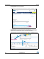
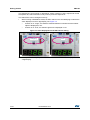
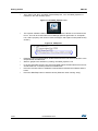
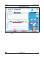
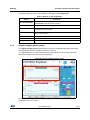
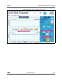
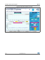
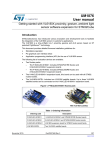
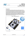
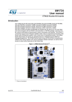
UM1796
User manual
VL6180X explorer kit (EVALKIT-VL6180X) software installation
Introduction
This document provides detailed firmware installation guidelines for a standalone
demonstration, a PC graphical user interface (GUI) and an application programming
interface (API) for the use of VL6180X explorer kit (EVALKIT-VL6180X). This explorer kit
consists of the VL6180X plug-in board and the STM32 F401RE Nucleo board. This product
is part of STMicroelectronics offering for demonstration and development tools designed
around the VL6180X, 3-in-1 proximity, gesture and ALS sensor, based on ST patented
FlightSense™ technology.
Figure 1. EVALKIT-VL6180X
Table 1. Ordering information
Ordering code
EVALKIT-VL6180X
February 2015
Description
VL6180X plug-in board and STM32 F401RE Nucleo board
DocID026604 Rev 2
1/32
www.st.com
32
Contents
UM1796
Contents
1
2
Getting started . . . . . . . . . . . . . . . . . . . . . . . . . . . . . . . . . . . . . . . . . . . . . . 3
1.1
Document references . . . . . . . . . . . . . . . . . . . . . . . . . . . . . . . . . . . . . . . . . 3
1.2
Hardware description . . . . . . . . . . . . . . . . . . . . . . . . . . . . . . . . . . . . . . . . . 3
1.3
EVALKIT-VL6180X demonstration software installation . . . . . . . . . . . . . . . 4
1.3.1
Demonstration software suite . . . . . . . . . . . . . . . . . . . . . . . . . . . . . . . . . 4
1.3.2
STM32 F401RE driver and upgrade firmware installation . . . . . . . . . . . . 6
1.3.3
Installation of the VL6180X standalone demonstration . . . . . . . . . . . . . . 9
1.3.4
Installation of the VL6180X PC software graphical user interface (GUI) 11
VL6180X software GUI description . . . . . . . . . . . . . . . . . . . . . . . . . . . . 14
2.1
Ranging . . . . . . . . . . . . . . . . . . . . . . . . . . . . . . . . . . . . . . . . . . . . . . . . . . 14
2.1.1
Signal strength (power) graph . . . . . . . . . . . . . . . . . . . . . . . . . . . . . . . . 15
2.1.2
Actual distance (ToF) graph . . . . . . . . . . . . . . . . . . . . . . . . . . . . . . . . . . 16
2.1.3
Actual distance (ToF) graph showing thresholds . . . . . . . . . . . . . . . . . . 18
2.2
Ambient light sensor (ALS) . . . . . . . . . . . . . . . . . . . . . . . . . . . . . . . . . . . . 18
2.3
Options . . . . . . . . . . . . . . . . . . . . . . . . . . . . . . . . . . . . . . . . . . . . . . . . . . . 21
2.3.1
Recording Data Logs . . . . . . . . . . . . . . . . . . . . . . . . . . . . . . . . . . . . . . . 21
2.3.2
Recording I2C transactions . . . . . . . . . . . . . . . . . . . . . . . . . . . . . . . . . . 21
2.4
Help . . . . . . . . . . . . . . . . . . . . . . . . . . . . . . . . . . . . . . . . . . . . . . . . . . . . . 22
2.5
Data log file . . . . . . . . . . . . . . . . . . . . . . . . . . . . . . . . . . . . . . . . . . . . . . . 23
2.6
I2C log file . . . . . . . . . . . . . . . . . . . . . . . . . . . . . . . . . . . . . . . . . . . . . . . . . 25
2.7
Range offset calibration procedure . . . . . . . . . . . . . . . . . . . . . . . . . . . . . 26
3
VL6180X application programming interface (API) . . . . . . . . . . . . . . . 29
4
Revision history . . . . . . . . . . . . . . . . . . . . . . . . . . . . . . . . . . . . . . . . . . . 31
2/32
DocID026604 Rev 2
UM1796
Getting started
1
Getting started
1.1
Document references
Table 2. Document references
1.2
Description
DocID
Data brief - VL6180X plug-in and STM32F401 Nucleo board evaluation kit
DocID026599
Datasheet - VL6180X proximity and ambient light sensing (ALS) module
DocID026171
AN4545: application note: Getting started - VL6180X basic ranging
DocID026571
AN4466 application note: VL6180X cover glass selection
DocID026155
AN4478 application note: Using multiple VL6180Xs in a single design
DocID026250
Hardware description
The VL6180X plug-in is a board for use with most of the Arduino compatible connectors.
With its companion software package, it is particularly well suited for STM32 Nucleo boards.
To function in a nominal way, the VL6180X must be connected to the STM32 Nucleo board
as shown in Figure 2. and Figure 3
Figure 2. VL6180X plug-in connected to STM32 Nucleo board
DocID026604 Rev 2
3/32
32
Getting started
UM1796
Figure 3. VL6180X plug-in connected to STM32 Nucleo board
The interconnection between STM32 Nucleo board and VL6180X plug-in is optimal with
NUCLEO-F401RE.
The NUCLEO-F401RE is connected to the PC via a cable ended by a mini USB connector.
1.3
EVALKIT-VL6180X demonstration software installation
ST delivers a software suite allowing the user to discover, through a standalone
demonstration and a PC graphical user interface (GUI), the VL6180X ranging and ambient
light sensing (ALS) features.
1.3.1
Demonstration software suite
The demonstration software suite is available at the bottom of the page of the EVALKITVL6180X http://www.st.com/web/en/catalog/tools/PF260896. (see Figure 4).
This software suite is consisting of:
4/32
•
STSW-LINK008, Windows vista , 7 and 8 driver for STM32 F401RE Nucleo board. This
driver must be first installed.
•
STSW-LINK007, STM32 F401RE Nucleo board communication driver with PC.
When STSW-LINK008 and STSW-LINK007 firmware’s are installed the STM32
F401RE Nucleo board is configured and ready to use with a PC.
•
STSW-IMG-001, binary code to be downloaded into STM32 F401RE microcontroller in
order to enable the EVALKIT-VL6180X standalone demonstration, showing on the
display the result of a range or an ALS measurement. This stand-alone demonstration
will start each time the USB cable is plugged between the EVALKIT-VL6180X and the
PC.
In standalone demonstration mode, the USB cable is only used to supply the EVALKITVL6180X, no data are transferred on DP and DN.
DocID026604 Rev 2
UM1796
Getting started
•
Note:
STSW-IMG002, this executable enables the graphical user interface (GUI) on the PC.
The GUI shows, on the PC screen, the result of a range or an ALS measurement and
allows the user to discover and test the different VL6180X settings.
When the GUI is in use the display of the EVALKIT-VL6180X is disabled.
Figure 4. EVALKIT-VL6180X web page on st.com
DocID026604 Rev 2
5/32
32
Getting started
1.3.2
UM1796
STM32 F401RE driver and upgrade firmware installation
STSW-LINK008: Windows USB driver installation
•
In EVALKIT-VL6180X page select STSW-LINK008
Figure 5. NUCLEO-F401RE Windows USB driver installation - step 1
•
Then Click on “Download”
Figure 6. NUCLEO-F401RE Windows USB driver installation - step 2
6/32
DocID026604 Rev 2
UM1796
Getting started
•
Following windows: From stsw-link008.zip, by unpacking the .zip file and running
stlink_winusb_install.bat. This will install the necessary USB drivers to allow
communications between the Nucleo board and the PC.
Figure 7. NUCLEO-F401RE Windows USB driver installation - step 3
•
Plug a USB cable between the PC and NUCLEO-F401RE board. Allow the board
driver installations to complete before proceeding.
STSW-LINK007: NUCLEO-F401RE communication driver with the PC
•
In EVALKIT-VL6180X page select STSW-LINK007
Figure 8. Nucleo-F401RE communication driver with PC installation - step 1
DocID026604 Rev 2
7/32
32
Getting started
•
UM1796
Following windows: Click on “Download”
Figure 9. Nucleo-F401RE communication driver with PC installation - step 2
•
Following windows: From stsw-link007.zip by unpacking .zip file and running STLinkUpgrade.exe. Press 'device connect' in the application. Then press 'YES’ to
upgrade the communication driver with the PC with the last version.
Figure 10. Nucleo-F401RE communication driver with PC installation - step 3
3
2
1
8/32
DocID026604 Rev 2
UM1796
Getting started
1.3.3
Installation of the VL6180X standalone demonstration
Note:
If not already done, plug VL6180X plug-in on STM32 F401RE Nucleo board
To install VL6180X standalone demonstration
•
In EVALKIT-VL6180X page select STSW-IMG001
Figure 11. VL6180X standalone demonstration installation - step 1
•
Following windows click on “Download” then save it
Figure 12. VL6180X standalone demonstration installation - step 2
•
then drag and drop the “.bin” file to Nucleo
Figure 13. VL6180X standalone demonstration installation - step 4
Drag and drop
DocID026604 Rev 2
9/32
32
Getting started
UM1796
The explorer kit is now running in “standalone” mode, meaning no PC is required to control
the explorer kit, USB connection is only used to power the explorer kit.
The switch SW1 can be changed on the fly.
•
When running in Standalone mode, the SW1 switch on the VL6180X plug-in selects the
value displayed on the 4-digit display, see Figure 14.
–
If switch is on “range”, the distance detected between VL6180X and the nearest
object is displayed in mm.
–
If switch is on “ALS”, the ambient light level is displayed in Lux.
Figure 14. Value displayed versus SW1 switch setting
Ranging
•
10/32
ALS
Move your hand or any object in front of VL6180X and read the value displayed on the
4-digit display.
DocID026604 Rev 2
UM1796
1.3.4
Getting started
Installation of the VL6180X PC software graphical user interface (GUI)
The GUI shows, on the PC screen, the result of a range or an ALS measurement and allows
the user to discover and test the different VL6180X settings.
Caution:
As soon as the PC software runs, the VL6180X plug-in display is Off and values are only
visible on the PC screen.
To install the PC graphical user interface
•
In EVALKIT-VL6180X page select STSW-IMG002
Figure 15. Installation of the VL6180X PC software GUI - step 1
•
Following windows click on “Download”
Figure 16. Installation of the VL6180X PC software GUI - step 2
17
DocID026604 Rev 2
11/32
32
Getting started
•
UM1796
Then “Save” and “Run” VL6180X_ExplorerSetup.exe, icon “VL6180X_Explorer” is
installed on the user desktop space.
Figure 17. VL6180X_Explorer icon
•
The explorer software needs to know which COM Port the Nucleo is connected to the
PC on. This can be found under Device Manager (Mouse right button on “Computer”
icon, select “property” then click on “Device manager” and expand “Ports (COM & LPT)
section”)
Figure 18. COM ports.
12/32
•
Read the COM Port listed against “STMicroelectronics STLink Virtual COM Port” in the
drop-down list of COM Ports.
•
Start PC graphic user interface by clicking “VL6180X_Explorer” icon
•
In the port list select the port com previously listed against “STMicroelectronics STLink
Virtual COM Port” in the drop-down list of COM Ports
•
Press the Connect button to establish communications between the software and the
board.
•
Press the Start/Stop button to start the device (Start then when running “stop”)
DocID026604 Rev 2
UM1796
Getting started
Figure 19. Starting the device
Start
•
Values are now displayed on the PC screen and no more on the VL6180X plug-in
display.
DocID026604 Rev 2
13/32
32
VL6180X software GUI description
2
UM1796
VL6180X software GUI description
The VL6180X software GUI contains several tabs that can be used to display, calibrate and
configure various features of the VL6180X. The available tabs are:
2.1
•
Ranging, see Section 2.1
•
ALS, see Section 2.2
•
Options, see Section 2.3
•
Help, see Section 2.4
Ranging
When the VL6180X explorer software is launched, the Ranging tab is displayed containing
the ranging sensor interface as shown in Figure 20.
In ranging mode, the VL6180X explorer measures absolute range from the sensor to a
target. This is shown in graphical form in the two graphs displayed:
•
Signal Strength (Power), see Section 2.1.1
•
Actual Distance (Time of Flight - TOF), see Section 2.1.2
To use the software, place a target above the VL6180X device and click on Start. The
device begins ranging and the Signal Strength (Power) and Actual Distance (ToF) graphs
will display data in real-time and numerically in the settings and display boxes to the right.
Figure 20. Ranging tab
14/32
DocID026604 Rev 2
UM1796
VL6180X software GUI description
The buttons listed in Table 3 are available at the bottom of the Ranging tab.
Table 3. Buttons in the ranging tab
Button
2.1.1
Description
Start (Pause/Resume)
Click on Start to begin ranging. The Start button changes to
Pause/Resume while the device is ranging.
Stop
Click on Stop to stop ranging.
Reset
The Reset button resets the I2C communications interface between the
application and the VL6180X.
COM Ports
The COM Ports box display a list of available connection ports to connect
the VL6180X to the PC.
Reset Comms
Resets the COM Port connection to the VL6180X software.
Baud Rate
Port COM speed (bits per second). Default is 19200.
Connect
Connects the chosen COM Port to the VL6180X explorer software.
Signal strength (power) graph
The Signal strength (power) graph plots, in real time, the Signal Rate (Mega Counts per
Second) returned from the target, as shown in Figure 21.
The Signal Rate can be viewed as a measure of the reflectance of the target, with high
reflectance targets producing stronger signal rates.
Figure 21. Signal strength (power) graph
To the right of the Signal strength (power) graph the settings and display information
described in Table 4 is shown.
DocID026604 Rev 2
15/32
32
VL6180X software GUI description
UM1796
Table 4. Signal strength (power) information
Field
Description
Max Convergence
time (ms)
This is the maximum time allowed for a range measurement to be made.
No range output is given if the system has not converged within the
specified time (that is, no target or target out of range). Maximum
convergence time default = 30ms.
Inter Meas period
(ms)
Inter measurement period is the time delay between measurements in
continuous range mode. Range = 10ms to 2.55 seconds (default = 50ms).
SNR threshold
The minimum SNR threshold below which a range measurement is
rejected. The default value is 0.1.
ECE factor
The VL6180X has a built in Early Convergence Estimate feature. When
enabled, the rate of convergence is automatically calculated 0.5ms after
the start of each measurement. If the return count is below the ECE
threshold the measurement is aborted. This minimizes power consumption
and reduces red glow when there is no target.
The ECE threshold is calculated as follows (example with ECE factor =
80%):
ECE threshold =
(80% x 0.5 x 15360) /SYSRANGE__MAX_CONVERGENCE_TIME (in ms)
Offset factor (mm)
This is fixed range offset parameter, which can be manually applied by the
user to introduce a range adjustment.
2X Scaling
Default setting: maximum range measurement up to 400mm (if box not
ticked, maximum range can be approximatively 200 or 400mm)(1)
Return Signal Rate
Display
Manual adjustment of the Signal Rate vertical axis permissible range.
Scale can be adjusted from 0...240 at the lower limit to 10...300 at the
upper limit.
Continual
Changes ranging mode from single-shot to continuous mode.
Gesture Help
Provides some examples of gesture hand movements and signal
comparison from a classical IR sensor with the VL6180X.
1. Under certain conditions, the VL6180X will detect targets above the specified 100mm. With the “2x Scaler”
default setting, the maximum distance measurement can be up to 400 mm with a reported granularity of
2mm. For applications requiring a granularity of 1mm, scaling factor must be set to 1 and maximum
distance measurement will be reported up to 200mm.
2.1.2
Actual distance (ToF) graph
The Actual distance (ToF) graph plots, in real time, range measurements (see Figure 22).
The vertical axis can be changed using the Range Measurement display Scale. If a target
is not detected, the maximum range is displayed.
16/32
DocID026604 Rev 2
UM1796
VL6180X software GUI description
Figure 22. Actual distance (ToF) graph
The VL6180X explorer can be run in single-shot ranging mode (default) or continuous
ranging mode (by ticking the Continual check box to the right of the Signal Strength
(Power) graph, see Figure 21). If in Continual ranging mode the time between
measurements can be changed by adjusting the Inter-Meas Period (ms).
The Actual Distance (ToF) graph can be changed to show threshold information, see
Section 2.1.3.
To the right of and above the Actual Distance (ToF) graph, the information described in
Table 5 is displayed.
Table 5. Actual distance (ToF) information
Field
Description
Actual Distance (ToF)
Display
Manual adjustment of the Range vertical axis permissable range. Scale
can be adjusted from 0...110 at the lower limit to 10...255 at the upper limit.
Enable
Check the Enable box to allow thresholding to be enabled.
Low Threshold
Manual adjustment of the lower threshold limit (default is 60mm).
When enabled, this threshold line is shown in the Actual Distance (ToF)
graph. See Actual distance (ToF) graph showing thresholds.
High Threshold
Manual adjustment of the upper threshold limit (default is 70mm).
When enabled, this threshold line is shown in the Actual Distance (ToF)
graph. See Actual distance (ToF) graph showing thresholds.
Raw Range (mm)
This is the range measurement including the Offset Factor.
Max & Min (mm)
These are post-processed measurement statistics to make noise
evaluation easier to characterize. The max and min are the range data
measured by the sensor over 100 measured sample points.
DocID026604 Rev 2
17/32
32
VL6180X software GUI description
2.1.3
UM1796
Actual distance (ToF) graph showing thresholds
The thresholding feature allows the user to define upper and lower limits and be alerted as
the range measurements transition across these limits by the display changing color.
Figure 23 shows examples of the Actual Distance (ToF) graph with high and low
thresholding enabled. It shows a minimum threshold of 60 mm, a maximum threshold of
150 mm and range measurements above and below the thresholds.
If the range measurement goes below the lower threshold the graph turns green as shown
in the top graph. If it goes above the upper threshold the graph turns pink as shown in the
lower graph. The graph will stay pink/green, till the lower/upper threshold is crossed.
Thresholding is enabled by checking the Enable check box (see Table 5) and the upper and
lower threshold settings can be modified in the High & Low Threshold settings.
Figure 23. Actual distance graphs showing high and low thresholds
Low threshold reached: with green background display
High threshold reached: with red background display
2.2
Ambient light sensor (ALS)
The ambient light sensor can be activated in the ALS tab. This tab displays the ALS Count
graph showing ALS Lux/count versus Samples, as shown in Figure 24. Table 6 lists the
buttons available in the ALS tab.
18/32
DocID026604 Rev 2
UM1796
VL6180X software GUI description
Figure 24. ALS tab
Table 6. Buttons in the ALS tab
Button
Description
Start (Pause/Resume)
Click on Start to begin measuring the ALS count. The Start button then
changes to Pause/Resume.
Stop
Click on Stop to stop measuring the ALS count.
Reset
The Reset button resets the I2C communications interface between the
application and the VL6180X.
COM Ports
The COM Ports list shows available device ports.
Reset Comms
The Reset Comms button resets the comms between the device and the
software.
Baud Rate
Port COM speed (bits per second). Default is 19200.
To the right of the ALS graph the information described in Table 7 is displayed.
Table 7. ALS information
Field
Description
ALS Count
This is the raw output from the ambient light sensor. The count is
proportional to the light level. The count output is a 16-bit binary value.
ALS Lux
The ALS Count value is converted automatically to a Lux value depending
on the ALS Lux Res, ALS Gain, Integration Period and ALS Scaler
settings.
DocID026604 Rev 2
19/32
32
VL6180X software GUI description
UM1796
Table 7. ALS information (continued)
Field
20/32
Description
Sampling Rate (Hz)
The number of ALS samples measured per second (PC dependent).
ALS Gain
Displays the actual gain value applied corresponding to the ALS Gain
Selection setting.
ALS Max &Min
These are post-processed measurement statistics to make noise
evaluation easier to characterize. The max, min and mean are the ALS
data measured by the sensor over 100 sample points.
ALS Lux Res
This calibrates the ALS Lux/count conversion. The characterized ALS Lux
Res is 0.32 (default).
Integration Period
(ms)
The integration period is the time range, during a single ALS measurement,
over which Lux data is captured and averaged. The default integration
period is 100 ms.
Inter Meas Period
(ms)
The inter-measurement period is the time between each ALS
measurement in continuous ALS mode. The default inter-measurement
period is 10 ms.
Continual
Changes ALS mode from single-shot to continuous mode.
ALS Gain Selection
This is the device register setting 0 to 7. The corresponding gain value is
displayed in the ALS Gain box. Gain settings are as follows:
0: ALS Gain = 1
1: ALS Gain = 1.25
2: ALS Gain = 1.67
3: ALS Gain = 2.5
4: ALS Gain = 5
5: ALS Gain = 10
6: ALS Gain = 20
7: ALS Gain = 40
ALS Scaler
The count output is a 16-bit value. Internally, the device uses a 20-bit
counter. Gain and integration time are normally used to increase sensitivity.
However, if this is not sufficient and more resolution is required in low light,
the ALS scaler can be used to access the 4 LSBs of the internal counter.
Apply a value in the range 2 to 15 to apply additional gain.
ALS Count Upper
This is the maximum scale value for the vertical axis. The default value is
15000. The user can input a new value to scale the ALS Count graph up
or down as required for measurements, up to a maximum value of 65,000.
Auto Gain
Enables and disables the auto-gain feature. Auto-gain automatically
adjusts the gain selection in response to the current ALS Count value in
order to provide and effective dynamic range for the current lighting
conditions.
Auto Gain Count
Thresh Min
The manual Auto Gain ALS count threshold minimum value in Auto Gain
mode.
Auto Gain Count
Thresh Max
The manual Auto Gain ALS count threshold maximum value in Auto Gain
mode.
DocID026604 Rev 2
UM1796
2.3
VL6180X software GUI description
Options
The Options tab is used to enable I2C logging or data logging during ranging and ALS
modes.
2.3.1
Recording Data Logs
For every measurement, relevant system data is stored in a comma separated value file
(.csv) identified by date and time.
To enable data logging, in the Options tab, check the Enable Data Log box, see Figure 25.
Data logging should be selected either prior to starting measurements or during the paused
state.
Figure 25. Enable data logging
Data log files are created with unique filenames and stored in:
C...\Users\username\AppData\Local\STMicroElectronics\VL6180XEVK\DataLog\.
See 2.5: Data log file for an example.
Before you can switch off data logging, the device must first stop ranging or ALS
measurements. To do this, click on the Stop button in the Ranging tab, see Section 2.1:
Ranging.
2.3.2
Recording I2C transactions
The Enable I2C Logging option is used to record I2C transactions during ranging or ALS
mode. The I2C transactions are stored in a unique file (.txt) identified by date and time.
To enable I2C logging, in the Options tab, check the Enable I2C Logging box, see
Figure 25.
DocID026604 Rev 2
21/32
32
VL6180X software GUI description
UM1796
I2C log files are stored in:
C...\Users\username\AppData\Local\STMicroElectronics\VL6180XEVK\I2C\.
See 2.6: I2C log file for an example.
Before you can switch off I2C logging, the device must first stop ranging or ALS
measurements. To do this, click on the Stop button in the Ranging tab, see Section 2.1.
Figure 26. Enable I2C logging
2.4
Help
The Help tab provides links to documents and on line resources which provide details on
the setup and functionalities of the VL6180X explorer and also details on the software
version:
22/32
•
HELP: To access help index
•
HW User Manual: To access hardware user manual
•
SW User Manual: To access software user manual
•
www.ST.com/VL6180X: To access ST VL6180X product and support page
•
About GUI Version: Provides the GUI version installed
DocID026604 Rev 2
UM1796
2.5
VL6180X software GUI description
Data log file
Each data log is stored in a uniquely named .csv file. The data log filename configuration is
data_log_DD_MMM_YYYY_HHMM_SS_sss.csv.
Where:
•
DD_MMM_YYYY is the date the log file was created, for example 17_Apr_2014
•
HHMM is the time (hours, minutes) the log file was created, for example 1025
•
SS_sss is the time (seconds, milliseconds) the log file was created, for example
17_367.
An example of a ranging data log is shown in Figure 27
Figure 27. Data log file example
DocID026604 Rev 2
23/32
32
VL6180X software GUI description
UM1796
Range output column data definitions
A: TimeStamp: The time stamp is generated by the EVK software so the data can easily be
plotted on a graph, and it represents the time of start of the test. There is latency, due to
the USB interface, to send and receive data to the sensor.
B: Range Execution Time (ms): The range execution time is measured by the software for
the amount of time that the test was executed to the time the data was received over the
USB interface to display the data.
C: Range Val: The range value read directly from RESULT__RANGE_VAL (0x0062) in the
VL6180X part on the EVK. This value includes the crosstalk compensation.
D: True Range: The range value read directly from the VL6180X part on the EVK. There is
no difference between this value and the Range Value.
E: True Range Smoothed: The Raw Range value read from RESULT__RANGE_RAW
(0x0064) on the VL6180X that would show a range measured without any stray light
compensation.
F to I: Max, Min, Mean, Standard Deviation: Statistical data on the range data in mm
gathered since the EVK software was started or the statistics were reset. Stopping and
starting the capture will create a new file, but not reset the statistics.
J: Rtn Signal Rate: The actual count rate of signal returns of light measured by the return
sensor when the laser is active on the return array. This is calculated by the formula:
RESULT__RANGE_RETURN_SIGNAL_COUNT (0x006C)
-----------------------------------------------------------------------------------------------------------------------------------------------------------RESULT__RANGE_RETURN_CONV_TIME (0x007C)
This data is read directly from the VL6180X. Note: There are two photon triggering
arrays. The first reference array is the reference array to measure the time photons have
left the laser and the second return array is the array used to measure the time that the
photons traveled to the target and back to the sensor.
K: Ref Signal Rate: The actual count rate of signal returns of light measured by the
reference sensor when the laser is active. This is calculated by the formula:
RESULT__RANGE_REFERENCE_SIGNAL_COUNT (0x0070)
----------------------------------------------------------------------------------------------------------------------------------------------------------------------RESULT__RANGE_REFERENCE_CONV_TIME (0x0080)
L: Rtn Signal Count: This is the amount of sensor counts triggered by the return array on
the VL6180X when the laser is active. This data is read directly from the VL6180X.
24/32
DocID026604 Rev 2
UM1796
2.6
VL6180X software GUI description
I2C log file
Each I2C log is stored in a uniquely named .txt file. The I2C log filename configuration is
i2c_output_DD_MMM_YYYY_HHMM_SS_sss.txt.
Where:
•
DD_MMM_YYYY is the date the log file was created, for example 07_May_2013
•
HHMM is the time the log file was created, for example 1553
•
SS_sss is the time (seconds, milliseconds) the log file was created, for example
17_367.
An example of a I2C log is shown in Figure 28.
Figure 28. I2C log file example
DocID026604 Rev 2
25/32
32
VL6180X software GUI description
UM1796
2.7
Range offset calibration procedure
Note:
If a measurement with an accuracy below 10 mm is required, offset calibration must be
done.
An offset calibration is performed for each VL6180X module during the final test of the
manufacturing process, and stored into the NVM. So, the ranging measurement reported by
the product should be very close to the actual distance between a target and the VL6180X
module. Despite this offset calibration, you may notice eventually a significant offset due to
the soldering of the VL6180X module on the plug-in. In this case, the VL6180X evaluation
kit provides you with the possibility to make a manual offset calibration
The calibration procedure described below is efficient but will not deliver the highest
precision.
For precise offset calibration refer to: AN4545 VL6180X basic ranging application note section 4.1.1
Note:
•
Put the jacket delivered with the VL6180X explorer board, or a grey paper, horizontally
on the 4 digit display and above the VL6180X: this corresponds to the distance of 8 mm
between the target and the VL6180X.
•
To have a precise measurement, set the max value of the “range measurement
display” to 30. (see Figure 29)
•
Check the value of “Raw Range”, if the “Raw range” does not equal to 8 then the “offset
factor” value must be modified.
•
in the following example, before manual offset calibration, the “Raw range” reports a
value of 22 mm (see Figure 29), while the actual distance of the target is 8mm. The
“offset factor” must be adjusted from 30 to 15, reducing the raw range from 22mm
before offset calibration back to the true value of 8mm after offset calibration ( see
Figure 30).
Each time you modify the “offset factor” you have to do a “stop” “start” bottom sequence.
Each time the EVALKIT-VL6180X is switched-off, the “offset factor” value is cleared back to
the factory calibration, so, if previously manually modified, the “offset factor” must be
reloaded at the next switch-on of the EVALKIT-VL6180X.
26/32
DocID026604 Rev 2
UM1796
VL6180X software GUI description
Figure 29. Before offset calibration procedure
DocID026604 Rev 2
27/32
32
VL6180X software GUI description
UM1796
Figure 30. After Offset calibration procedure
28/32
DocID026604 Rev 2
UM1796
3
VL6180X application programming interface (API)
VL6180X application programming interface (API)
Previous chapters described how to use EVALKIT-VL6180X in demonstration mode, this
chapter gives information to use EVALKIT-VL6180X as a development tool.
STSW-IMG003 contains VL6180X API
API features
• VL6180X application programming interface (API) source code (C language)
• Full ranging and ALS features control
• API structured in a way it can be easily ported/compiled on any microcontroller platforms
• Several examples showing how to use API to perform ranging and ALS measurements
• Complete Nucleo STM32 F401 project (source code + binary) working with VL6180X
explorer expansion board (under Keil IDE)
• API documentation (.csh and .html)
Description
The VL6180X API is a set of C functions controlling the VL6180X (init, ranging, ALS,…) to
enable the development of end-user applications. This API is structured in a way it can be
compiled on any kind of platforms through a well isolated platform layer (mainly for low level
I2C access). Several code examples are provided to show how to use API and perform
ranging and ALS measures. A complete Nucleo F401 + VL6180X expansion board project
is also provided (Keil IDE required to compile the project) as well as the pre-compiled binary
that can be directly used.
STSW-IMG003 installation
•
In EVALKIT-VL6180X page select STSW-IMG003
Figure 31. VL6180X API installation - step 1
DocID026604 Rev 2
29/32
32
VL6180X application programming interface (API)
•
Following windows click on “Download”
Figure 32. VL6180X API installation - step 2
30/32
•
Save and unzip STSW-IMG003.zip
•
User has now all information to develop its own application with VL6180X
•
The best way to discover VL6180X API features is to open
API_Documentation-proximity.chm file in the DOCS folder.
DocID026604 Rev 2
UM1796
UM1796
4
Revision history
Revision history
Table 8. Document revision history
Date
Revision
Changes
12-Aug-2014
1
Initial release.
03-Feb-2015
2
Remove VL6180X plug-in hardware information
Update Section 1.3.1: Demonstration software suite
DocID026604 Rev 2
31/32
32
UM1796
IMPORTANT NOTICE – PLEASE READ CAREFULLY
STMicroelectronics NV and its subsidiaries (“ST”) reserve the right to make changes, corrections, enhancements, modifications, and
improvements to ST products and/or to this document at any time without notice. Purchasers should obtain the latest relevant information on
ST products before placing orders. ST products are sold pursuant to ST’s terms and conditions of sale in place at the time of order
acknowledgement.
Purchasers are solely responsible for the choice, selection, and use of ST products and ST assumes no liability for application assistance or
the design of Purchasers’ products.
No license, express or implied, to any intellectual property right is granted by ST herein.
Resale of ST products with provisions different from the information set forth herein shall void any warranty granted by ST for such product.
ST and the ST logo are trademarks of ST. All other product or service names are the property of their respective owners.
Information in this document supersedes and replaces information previously supplied in any prior versions of this document.
© 2015 STMicroelectronics – All rights reserved
32/32
DocID026604 Rev 2