1
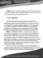
USER MANUAL
HANDBUCH
HANDLEIDING
MANUEL DESCRIPTIF
РУКОВОДСТВО ПОЛЬЗОВАТЕЛЯ
КЕРІВНИЦТВО КОРИСТУВАЧА
SIS-PMS-LAN PROGRAMMABLE SURGE
PROTECTOR WITH LAN INTERFACE
Silver Shield programmable surge protector
with LAN interface
Silver Shield programmierbare und
fernbedienbare Steckdosenleiste mit LANAnschluss
Silver Shield programmeerbare stekkerdoos
met LAN interface
Silver Shield Boîtier commandé à distance et
programmable avec prise LAN
Программируемый сетевой фильтр с LANинтерфейсом
Програмований мережевий фільтр з LANінтерфейсом
2
All brands and logos are registered trademarks of their respective owners
SIS-PMS-LAN PROGRAMMABLE SURGE
PROTECTOR WITH LAN INTERFACE
1. Introduction
Congratulations with your purchase of this Silver shield Power
Manager. Your SIS-PMS-LAN is an advanced surge protector with power
management features. Four sockets are individually manageable via the
LAN interface.
The sockets can be switched on/off by a timer schedule, by user or
different events. It is also possible to pre-program the unit event timer
schedule (hardware schedule) and then disconnect SIS-PMS-LAN from
LAN and use it elsewhere. The device can be used as an advanced
standby-killer.
1.1. Features
•
•
•
•
The main rocker switch enables switching all the sockets on and off
In addition to it every manageable socket can be switched on and off
via the software control window or web browser
The unit can be pre-programmed via hardware-based schedule. The
hardware schedule will work even when the managing computer is
switched off
The unit will keep performing the programmed hardware time
schedule even after SIS-PMS-LAN is disconnected from the power
for some time
3
All brands and logos are registered trademarks of their respective owners
SIS-PMS-LAN PROGRAMMABLE SURGE
PROTECTOR WITH LAN INTERFACE
•
•
•
•
•
•
The manageable sockets can then be switched on and off by the
schedule, simple typical applications could be: “switch my
peripherals on every working day at 8:50 AM” etc
The manageable sockets can also be programmed with Power
Manager software to react whenever a certain event occurs
(Windows or other programs start-up/shutdown), simple typical
applications could be: “switch my scanner on when I want to scan”
or “switch my printer off whenever I exit Windows”
LAN interface: the unit can be assigned an IP address and/or a
network name as a shared LAN resource and can be afterwards
accessed and managed from anywhere within the local area network
or Internet
Built-in web-server: SIS-PMS-LAN can be managed from any
computer running Internet Explorer or any other web browser –
therefore a global access is possible
IP-filter and 64-bit password protected encryption of data guarantee
secure access to SIS-PMS-LAN
Real time Voltage monitor provides information about the actual
status of each manageable socket (on or off). This information can
be further utilized in various ways (e.g. to check the proper
execution of the switching commands)
4
All brands and logos are registered trademarks of their respective owners
SIS-PMS-LAN PROGRAMMABLE SURGE
PROTECTOR WITH LAN INTERFACE
1.2. Specifications
•
•
•
•
•
•
•
•
Input voltage: 220 – 230 VAC, 50 – 60 Hz
Maximum load: 10 A
Maximum power consumed by SIS-PMS-LAN: 2.5 W
Built in power supply and battery
Hardware schedule features:
• Maximum number of independent hardware schedule events –
16 per socket
• Time interval between the events – from 1 minute to 180 days
• Timer accuracy: no more than 2 seconds error per day providing
power is always present. Otherwise there can be an additional
(up to 2 seconds) error per each power off. There is no
accumulation of errors at all if NTP correction option is set (see
section 5.4 below)
Working temperature range: from +10 to +40 °C
Dimensions: 378 x 98 x 55 mm
Net weight: 1.0 kg
5
All brands and logos are registered trademarks of their respective owners
SIS-PMS-LAN PROGRAMMABLE SURGE
PROTECTOR WITH LAN INTERFACE
1.3. Hardware requirements
•
•
•
Local area network with RJ45 sockets
Any Internet-enabled computer connected to the local area network
Computer running Windows® 2000/XP/Vista or Windows 7 is
required for using the Power Manager software (use of this software
is not compulsory)
1.4. Package contents
•
•
•
•
SIS-PMS-LAN
User manual and Quick installation guide
RJ45 cross-over cable (red), RJ45 LAN cable (grey)
CD with Power Manager software for Windows
6
All brands and logos are registered trademarks of their respective owners
SIS-PMS-LAN PROGRAMMABLE SURGE
PROTECTOR WITH LAN INTERFACE
2. Indicators and controls of the SIS-PМS-LAN
Figure #1
Side panel #2
Non manageable
socket
Manageable socket 4
Main rocker
switch (Z)
Manageable socket 3
Power indicator
Manageable socket 2
Indicator
Socket 4
Manageable socket 1
Non manageable
socket
Side panel #1
Indicator
Socket 3
Indicator
Socket 2
Indicator
Socket 1
7
All brands and logos are registered trademarks of their respective owners
SIS-PMS-LAN PROGRAMMABLE SURGE
PROTECTOR WITH LAN INTERFACE
2.1. Side panel #1
Figure #2
Indicator
Schedule/LAN activity
Reset
Button (A)
Master Switch
Button (B)
LAN socket
IP Config
Button (C)
8
All brands and logos are registered trademarks of their respective owners
SIS-PMS-LAN PROGRAMMABLE SURGE
PROTECTOR WITH LAN INTERFACE
2.2. Side panel #2
Figure #3
Circuit breaker
Power cord
9
All brands and logos are registered trademarks of their respective owners
SIS-PMS-LAN PROGRAMMABLE SURGE
PROTECTOR WITH LAN INTERFACE
2.3. Indicators
•
•
•
•
•
•
Main rocker switch Z (see Figure #1 above) is lit – this means that
SIS-PMS-LAN is connected to the power supply and active
Power indicator (see Figure #1 above) is lit – this means that the
non-manageable sockets (marked with the sign
) are
switched on
The indicator Socket 1 (2,3,4) (see Figure #1 above) is lit – this
means that this particular socket is switched on
The indicator Schedule/LAN activity (see Figure #2 above) blinks
green – this means that there is some LAN activity taking place
The indicator Schedule/LAN activity (see Figure #2 above) blinks
red as the reset procedure is being executed
The indicator Schedule/LAN activity (see Figure #2 above) stays
red if an active hardware schedule for any socket exists
10
All brands and logos are registered trademarks of their respective owners
SIS-PMS-LAN PROGRAMMABLE SURGE
PROTECTOR WITH LAN INTERFACE
3. Installation
•
•
It is strongly recommended to avoid damp or wet places for
installation.
SIS-PMS-LAN should be connected to the European AC wall socket
of the standard DIN 49 440.
3.1. Getting started
•
•
•
•
Connect SIS-PMS-LAN to the wall socket first and then to the LAN
socket (or your computer LAN card) with the provided patch cord or
vice-versa.
SIS-PMS-LAN can now be switched on and off by means of the
Main rocker switch (Z).
Two (the first and the last) sockets of SIS-PMS-LAN are marked with
the symbol
. These two sockets are switched on and off by
means of the Main rocker switch (Z) and cannot be managed by the
computer – so they are called non-manageable sockets in this
manual.
If SIS-PMS-LAN is switched on then the red indicator POWER is lit.
In this case both non-manageable sockets are now live and
connected to the power supply.
11
All brands and logos are registered trademarks of their respective owners
SIS-PMS-LAN PROGRAMMABLE SURGE
PROTECTOR WITH LAN INTERFACE
•
•
•
•
•
•
•
The sockets: Socket 1, Socket 2, Socket 3 and Socket 4 can be
managed or pre-programmed by computer via LAN. They are called
manageable sockets in this manual.
The manageable sockets of SIS-PMS-LAN can be programmed to
be on or off. The current status of each manageable socket is
represented by the corresponding indicator which will be lit if socket
has power to it.
If the Main rocker switch (Z) (see figure #1 above) is turned off then
the manageable sockets cannot be switched on by either web server,
Power manager software or the hardware schedule.
As soon as you turn the Main rocker switch (Z) on then the web
server, Power manager software or the hardware schedule will be
able to turn the manageable sockets on and off.
Master switch button (B) (see figure #2 above) can also switch all
the manageable sockets on and off regardless of their current status
or schedule that is being executed. To switch them on you should
keep the button pressed for 1-2 seconds. To switch them off you
should keep the button pressed for more than 3 seconds.
To protect the connected devices from possible high current and
short circuit SIS-PMS-LAN is equipped with the automatic circuit
breaker.
NOTE: If the total power consumption (or peak power) of the
devices, connected to SIS-PMS-LAN exceeds 2200 Watts, the
circuit breaker may power SIS-PMS-LAN off. In this case, please,
12
All brands and logos are registered trademarks of their respective owners
SIS-PMS-LAN PROGRAMMABLE SURGE
PROTECTOR WITH LAN INTERFACE
remove the excessive load first and then press the Circuit breaker
button to restore the power supply (see figure #3 above).
To be able to use SIS-PMS-LAN you will now have to complete its
LAN configuration.
3.2. Preparing LAN configuration of SIS-PMS-LAN
Before configuring SIS-PMS-LAN hardware settings, please, let it
obtain its IP address. Follow the steps below:
• Make sure SIS-PMS-LAN is connected to the local network with the
provided RJ-45 cable (option A - recommended)
NOTE: you may prefer to connect SIS-PMS-LAN directly to the
managing computer LAN adapter (network card) using the supplied
crossover RJ-45 cable (option B)
•
•
•
Turn SIS-PMS-LAN off (with the Main rocker switch Z)
Press IP Config (C) button on the side control panel (see figure #2
above) with the tip of a pen
While holding it pressed, turn the Main rocker switch Z on and wait
for about 3 seconds until you hear the sockets switching twice
The above-mentioned procedure forces SIS-PMS-LAN to reset itself
to the default settings (see below) ...
13
All brands and logos are registered trademarks of their respective owners
SIS-PMS-LAN PROGRAMMABLE SURGE
PROTECTOR WITH LAN INTERFACE
•
•
•
•
•
•
•
IP: 192.168.0.254
Subnet mask: 255.255.255.0
Gateway: 192.168.0.1
DNS:0.0.0.0
DHCP: enabled
IP filtering: disabled
Power Manager client port: 5000
.. and then search for an IP address from your eventual DHCP
server If no DHCP server is found within 30 seconds, SIS-PMS-LAN will
then automatically revert to the default settings (see above, with IP:
192.168.0.254) and additionally disable DHCP option.
3.3. Power Manager installation
It is now time to identify which IP address has been obtained by SISPMS-LAN. We need to carry out the following:
• Insert the Power Manager CD into a PC CD-ROM drive. This PC
can be connected either to the same LAN where the device is (if you
chose option A section 3.2) or directly to the device with the
crossover RJ-45 cable (if you chose option B section 3.2)
• If for any reason the automatic setup does not work, then open CDROM drive in the My Computer window and launch SETUP.EXE
from the CD
• Follow instructions of the installation software
14
All brands and logos are registered trademarks of their respective owners
SIS-PMS-LAN PROGRAMMABLE SURGE
PROTECTOR WITH LAN INTERFACE
NOTE: Antivirus or firewall software may block connection to SISPMS-LAN. Please, configure antivirus/firewall to permit connection to
the IP address and port of your SIS-PMS-LAN
3.4. IP configuration
The utility Find SIS-PMS-LAN (see Figure #4 below) will run
automatically during the software installation but it can also be started
from Start/All Programs/Gembird/Power Manager. The IP range where
you would like to search for SIS-PMS-LAN will be set automatically
according to the IP settings of your LAN adapter but can be changed
manually in the Adapter subnet fields. Now press the Search button.
NOTE: only SIS-PMS-LAN within a local subnet can be found. If
your computer LAN adapter is not in the (default) subnet of SIS-PMSLAN (as might probably be the case if you chose option B section 3.2)
you will have to change its IP address manually to be able to find SISPMS-LAN. For example if you wish to find SIS-PMS-LAN (with the default
IP 192.168.0.254), the IP address of your computer should be set as
192.168.0.XXX (where XXX stands for any digit, for example 1) and the
subnet mask should be 255.255.255.0.
After the searching the IP addresses of the found SIS-PMS-LAN
devices will appear in the list box. Select SIS-PMS-LAN which you want
to access, and press the Open button (see Figure #4 below).
15
All brands and logos are registered trademarks of their respective owners
SIS-PMS-LAN PROGRAMMABLE SURGE
PROTECTOR WITH LAN INTERFACE
Figure #4
The window of your default internet browser will be then opened to
give you access to the built-in web-server. See section 4 below for the
further details.
16
All brands and logos are registered trademarks of their respective owners
SIS-PMS-LAN PROGRAMMABLE SURGE
PROTECTOR WITH LAN INTERFACE
4. The web server
Your SIS-PMS-LAN is equipped with a web-server which allows
managing the device using any web browser such as Internet Explorer
etc.
4.1. Web-server login page
To access the web server of SIS-PMS-LAN, just open Internet
Explorer (or other browser) and input the IP address of SIS-PMS-LAN
(for example http://192.168.1.241). If you have used Find SIS-PMS-LAN
utility to locate SIS-PMS-LAN then you will be taken to this webpage
automatically. Login page will then be displayed (see Figure #5 below).
NOTE: Java script must be enabled in your Internet Explorer (or
another browser) settings. Otherwise, you get an error message:
WARNING! JAVASCRIPT IS DISABLED!
Figure #5
The default password is 1. It is recommended to change the
password on the Device settings page (see section 4.4 below) after the
first login.
17
All brands and logos are registered trademarks of their respective owners
SIS-PMS-LAN PROGRAMMABLE SURGE
PROTECTOR WITH LAN INTERFACE
After a successful login you will face the Socket 1 Status page (see
section 4.2 below).
NOTE: There is a possibility that you might then need to open the
LAN settings page (see section 4.3 below) to complete the IP
configuration.
4.2. Socket page
There are 4 manageable sockets on SIS-PMS-LAN and so there are
4 pages corresponding to them. On each status page you can see the
status of the socket (on or off) and you have the Switch On (Switch Off)
button. Besides you can see the scheduled events for this socket.
The socket shown on the Figure #6 is currently off, it will be turned
on automatically on the 27th of June at 9:59 and on the 28th of June at
10:59 it will be switched off again. The shown two events will be executed
periodically, with a loop period of 2 days.
18
All brands and logos are registered trademarks of their respective owners
SIS-PMS-LAN PROGRAMMABLE SURGE
PROTECTOR WITH LAN INTERFACE
Figure #6
19
All brands and logos are registered trademarks of their respective owners
SIS-PMS-LAN PROGRAMMABLE SURGE
PROTECTOR WITH LAN INTERFACE
Below the page you can see the current time of the web-server and
eventual information about the last successful timer synchronization.
Automatic timer synchronization is used if Use NTP for timer correction
option is enabled (see section 4.4 below).
NOTE: If a certain socket has a switching fault, e.g. it should be
switched on but the whole device is switched off, or it should be off but it
does have voltage, then the warning message Wrong voltage on socket!
will be shown above the Event schedule (see Figure #6 above). This
message might also indicate that this socket is defective.
For setting up the socket schedule click Set schedule button. You
will face then the page shown below (see Figure #7).
20
All brands and logos are registered trademarks of their respective owners
SIS-PMS-LAN PROGRAMMABLE SURGE
PROTECTOR WITH LAN INTERFACE
Figure #7
21
All brands and logos are registered trademarks of their respective owners
SIS-PMS-LAN PROGRAMMABLE SURGE
PROTECTOR WITH LAN INTERFACE
Choose the date and time of the scheduled event. If you wish the
events to be executed periodically then check the Loop option and set the
loop period. To commit to your changes press the Apply button. To delete
the entered schedule press the Clear schedule button.
NOTE: The hardware schedule keeps running even when the device
is powered off. However it is recommended not to power off the device
for extended periods, because the built-in battery has a limited lifespan. If
the battery dies the schedule will be completely cleared. The total lifetime
of the battery is no less than 2 years if the device is powered off, and no
less than 5 years if the device is powered on.
22
All brands and logos are registered trademarks of their respective owners
SIS-PMS-LAN PROGRAMMABLE SURGE
PROTECTOR WITH LAN INTERFACE
4.3. LAN settings page
Figure #8
23
All brands and logos are registered trademarks of their respective owners
SIS-PMS-LAN PROGRAMMABLE SURGE
PROTECTOR WITH LAN INTERFACE
On the LAN settings page (see Figure #8 above) you can set up
DHCP, IP address, Subnet mask, Gateway, DNS server and IP filter (up
to 3 IP addresses can then be enabled for remote access).
The new settings will be applied immediately after you press the
Apply button.
IP address, Subnet mask, Gateway, DNS server will be used only if
the DHCP option is disabled.
If you set DHCP option it is recommended for your own convenience
to set up your DHCP server so that it always provides the same IP
address to SIS-PMS-LAN. To do that you will need to know the MAC
address of SIS-PMS-LAN. It can be found on this page or on the bottom
sticker of the device. The MAC address is fixed and cannot be changed.
DNS server address is important to be properly set up in case you
wish to enable the NTP timer correction option (see section 4.4 below).
IP filter option is needed to prevent unauthorized access to the
server. It restricts the web server access from any computer with IP
address different from IP1, IP2 and IP3. Make sure that you input IP1,
IP2, and IP3 correctly before enabling this option.
Power Manager client port is used for connecting with the Power
Manager software, normally it is not needed to change this setting.
24
All brands and logos are registered trademarks of their respective owners
SIS-PMS-LAN PROGRAMMABLE SURGE
PROTECTOR WITH LAN INTERFACE
4.4. Device settings page
On the device settings page you can setup name, password and
internal time of SIS-PMS-LAN (see Figure #9 below).
Figure #9
25
All brands and logos are registered trademarks of their respective owners
SIS-PMS-LAN PROGRAMMABLE SURGE
PROTECTOR WITH LAN INTERFACE
To be able to setup the schedule of SIS-PMS-LAN you have to first
setup its internal clock correctly. Enter the current local time and date.
Alternatively if the option Use NTP for timer correction is enabled (by
default) then the time will be taken from NTP server. The device will try to
connect with the server every 18 hours. The first synchronization would
take place in 15 seconds after you press the Apply button.
NTP server field should have a valid name of NTP server (by default
“pool.ntp.org”). If for any reason the NTP time correction doesn’t work
you can choose the best NTP server for your country via the website
www.pool.ntp.org.
NOTE: for NTP time correction to work properly the device should
have access to the Internet and have a proper DNS server setting (see
section 4.3 above).
Server name can be convenient to identify the web server if you
have more than one SIS-PMS-LAN. It is “Server 1” by default.
The password is necessary to access SIS-PMS-LAN both from your
web browser and the Power Manager software (see section 12 below).
This password is case-sensitive and can be up to 32 characters long.
Alphanumeric characters and spaces are allowed to be entered. Only the
first eight characters of the password are used to access the device with
the Power Manager software. You will need to enter this password in the
Add LAN device window (see section 6 below).
The Power Manager software accesses SIS-PMS-LAN via a certain
client port (by default 5000). You can change this port to any other
except port 80 which is always occupied by the web server.
26
All brands and logos are registered trademarks of their respective owners
SIS-PMS-LAN PROGRAMMABLE SURGE
PROTECTOR WITH LAN INTERFACE
Don’t forget to push the Apply button to save your settings.
4.5. Web-server logout
Having finished working with SIS-PMS-LAN, choose Log Out in the
main menu. If you don’t do this, you will be logged automatically after 10
minutes of inactivity. While you are logged to the web server, it can’t be
accessed from any other computer. If another user tries to access the
web server which is running an active session the error message will be
shown on the login page: Somebody with another IP has already logged
in. Try again later. In the meantime the Power Manager software (see
section 5) can still access the SIS-PMS-LAN.
27
All brands and logos are registered trademarks of their respective owners
SIS-PMS-LAN PROGRAMMABLE SURGE
PROTECTOR WITH LAN INTERFACE
5. Power Manager software
The Power Manager software is designed to support not only SISPMS-LAN but also other products of SIS family (SIS-BT, SIS-PM, SISPMS, MSIS-PM etc).
5.1. Finding SIS-PMS-LAN
To be able to manage preconfigured SIS-PMS-LANs, please, do the
following:
• Install Power Manager software v.4.0.0.0 (or higher) on a PC
connected to your local network. A socket icon will then appear in
your system tray
• With a right mouse click on the socket icon you will get access to the
Power Manager main menu. Choose LAN devices from the menu
(see Figure #10 below)
28
All brands and logos are registered trademarks of their respective owners
SIS-PMS-LAN PROGRAMMABLE SURGE
PROTECTOR WITH LAN INTERFACE
Figure #10
The LAN devices window (see Figure #11 below) will appear, click
Add button there to add a new SIS-PMS-LAN device.
29
All brands and logos are registered trademarks of their respective owners
SIS-PMS-LAN PROGRAMMABLE SURGE
PROTECTOR WITH LAN INTERFACE
Figure #11
In the Add LAN device window (see figure #12 below) please, enter
correct IP address, port number (5000 by default) and password (1 by
default) as configured on the Device settings page (see section 4.4 above)
of the web server. To disconnect from the device uncheck the option
Enable, set this option again to regain the access. Click OK button to
return to the LAN devices window.
30
All brands and logos are registered trademarks of their respective owners
SIS-PMS-LAN PROGRAMMABLE SURGE
PROTECTOR WITH LAN INTERFACE
Figure #12
Specified device should then appear with a green square next to it
and Connected status in the LAN devices window (see Figure #13 below).
31
All brands and logos are registered trademarks of their respective owners
SIS-PMS-LAN PROGRAMMABLE SURGE
PROTECTOR WITH LAN INTERFACE
Figure #13
•
To edit the LAN device, select it and click the Edit button, or just
double click on the LAN device
• To remove the LAN device, select it and click the Remove button.
You can select multiple LAN devices using Ctrl and Shift keys. You
can also remove all LAN devices by clicking the Clear button
HINT: Use the popup menu which can be activated by the right
mouse button click over the table.
32
All brands and logos are registered trademarks of their respective owners
SIS-PMS-LAN PROGRAMMABLE SURGE
PROTECTOR WITH LAN INTERFACE
If the status of SIS-PMS-LAN shows the device not to be Connected
- it could be due to the following reasons:
• Incorrect IP/Port/Password specified in the Add LAN device window
• PC is not connected to the local network
• You are trying to access SIS-PMS-LAN from the PC which is not
allowed to do so. Change PC IP address or change IP filter list in
SIS-PMS-LAN hardware settings (see section 4.3 above)
• SIS-PMS-LAN is not connected to local network. To check if SISPMS-LAN is on your local network you can do so-called ping test:
• Go to Start->Run
• Type cmd
• Type ping <SIS-PMS-LAN IP Address specified in utility> in
the window which would appear
Suppose SIS-PMS–LAN with IP address 192.168.2.189 is
connected to the local network. Then the cmd window will look as shown
on the Figure #14 below:
33
All brands and logos are registered trademarks of their respective owners
SIS-PMS-LAN PROGRAMMABLE SURGE
PROTECTOR WITH LAN INTERFACE
Figure #14
•
SIS-PMS-LAN is connected to local network (ping test is ok) but not
responding. Reset SIS-PMS-LAN by pressing the Reset button (A)
on the side control panel (see Figure #2 above) or switch it off and
then on again (see Figure #1 above)
NOTE: The Reset button A (see Figure #2 above) can sometimes
help if SIS-PMS-LAN can’t be accessed or works abnormally. The device
will then be restarted. All the IP settings and device settings will remain
the same as before, but the server time will be reset and all schedules
will become outdated.
34
All brands and logos are registered trademarks of their respective owners
SIS-PMS-LAN PROGRAMMABLE SURGE
PROTECTOR WITH LAN INTERFACE
5.2. Managing SIS-PMS-LAN
After successful connection, close LAN devices window. You can
now start managing SIS-PMS-LAN via the Power Manager interface.
Double click on the socket icon in the system tray or select Open from the
popup menu (see Figure #10 above). You will get the window of the main
control panel shown on the Figure #15 below.
Figure #15
35
All brands and logos are registered trademarks of their respective owners
SIS-PMS-LAN PROGRAMMABLE SURGE
PROTECTOR WITH LAN INTERFACE
Sockets should switch on and off (green color means the socket is
switched off; red color means the socket is switched on) when you double
click on them. Click the Settings button for each socket to access the
Settings dialog box (see Figure #16 below).
Figure #16
You can choose a different device and another socket from the
Device and Socket drop down list-boxes.
36
All brands and logos are registered trademarks of their respective owners
SIS-PMS-LAN PROGRAMMABLE SURGE
PROTECTOR WITH LAN INTERFACE
•
•
•
•
•
It is possible to give a name to the device and socket (for example
Printer or Scanner) using the Rename button
Check the System tray checkbox if you want to put the icon of the
socket into the system tray. You can choose the icon from drop
down list box. Such icon is a fast way to switch the device connected
to the socket on/off or check the device status
You can also assign a hot key to switch the socket on/off. Check the
Switch ON and Switch OFF checkboxes and specify the hot keys
To switch the socket on/off on Windows startup (wake up), check the
On Windows startup checkbox and choose the required action
To switch the socket on/off on the Windows shutdown (sleep), check
the On Windows shutdown checkbox and choose the required action
37
All brands and logos are registered trademarks of their respective owners
SIS-PMS-LAN PROGRAMMABLE SURGE
PROTECTOR WITH LAN INTERFACE
6. Power Manager core features
6.1. Setting up the hardware schedule
Using the Hardware schedule button available from the Settings
window (see section 5.2 above) you can create the hardware timer
schedule (see Figure #17 below). To add a new record, click the Add
button.
Figure #17
38
All brands and logos are registered trademarks of their respective owners
SIS-PMS-LAN PROGRAMMABLE SURGE
PROTECTOR WITH LAN INTERFACE
•
The window Add entry will appear (see Figure #18 below). In the
dialog box, specify the required time and the action
Figure #18
•
To edit the record, select it and click the Edit button or just double
click on the entry (see Figure #17 above). The window Edit entry will
appear (see Figure #19 below)
39
All brands and logos are registered trademarks of their respective owners
SIS-PMS-LAN PROGRAMMABLE SURGE
PROTECTOR WITH LAN INTERFACE
Figure #19
•
•
To remove the record, select it and click the Remove button (see
Figure #17 above). You can select multiple entries using Ctrl and
Shift keys. You can also remove all entries from the schedule by
clicking the Clear button (see Figure #17 above)
To repeat your event (for example if you want to perform the same
events every day) use the Loop button (see Figure #17 above) and
specify the loop time period in the Edit loop period window (see
Figure #20 below)
40
All brands and logos are registered trademarks of their respective owners
SIS-PMS-LAN PROGRAMMABLE SURGE
PROTECTOR WITH LAN INTERFACE
Figure #20
•
•
After the schedule record has been created, click the Apply button
(see Figure #17 above) to save the hardware timer schedule
changes. In case of incorrect entries, these will be highlighted and
an error message will appear. Click the Apply button again after
correcting all the errors
Use Sync button (see Figure #17 above) to synchronize device timer
with PC clock. Note that after synchronization past entries will be
removed from the schedule
HINT: Use the popup menu (see Figure #17 above) which can be
activated by the right mouse button click over the table.
The following are the rules for creating a correct schedule:
41
All brands and logos are registered trademarks of their respective owners
SIS-PMS-LAN PROGRAMMABLE SURGE
PROTECTOR WITH LAN INTERFACE
•
•
•
•
•
•
•
The new event time should be in the future
There can not be a duplicate entry
The total quantity of events can not exceed 16 per socket
The total quantity of events also depends on the total execution
period of the schedule
The interval between the present and the last entry can not exceed
180 days
Without loop the total execution period of the schedule can not
exceed 215 days
Loop period can not exceed 180 days
NOTE: The hardware schedule keeps running even when the device
is powered off. However it is recommended not to power off the device
for extended periods, because the built-in battery has a limited lifespan. If
the battery dies the schedule will be completely cleared. The total lifetime
of the battery is no less than 2 years if the device is powered off, and no
less than 5 years if the device is powered on.
6.2. Setting up software schedule
Using the Software schedule button available from the Settings
window (see section 5.2 above) you can create the software timer
schedule (see Figure #21 below).
42
All brands and logos are registered trademarks of their respective owners
SIS-PMS-LAN PROGRAMMABLE SURGE
PROTECTOR WITH LAN INTERFACE
NOTE: the software timer schedule will only be executed if the
managing computer is on and the Power Manager is launched.
Figure #21
•
To add a new task, click the Add button. The Add task window will
appear (see Figure #22 below)
43
All brands and logos are registered trademarks of their respective owners
SIS-PMS-LAN PROGRAMMABLE SURGE
PROTECTOR WITH LAN INTERFACE
Figure #22
In the Add task window, check Switch ON time and/or Switch OFF
time checkboxes and specify the time to switch the socked on and/or off.
If you want the same event to be performed periodically, check Perform
task every checkbox and specify the time interval. You can also add
remarks about the task in the Comment field. To disable the task,
uncheck the Enabled checkbox and to enable the task again, re-check
the checkbox.
44
All brands and logos are registered trademarks of their respective owners
SIS-PMS-LAN PROGRAMMABLE SURGE
PROTECTOR WITH LAN INTERFACE
•
To edit the task, select it (see Figure #21 above) and click the Edit
button or just double click on the task. The Edit task window will
appear (see Figure #23 below)
Figure #23
•
To remove the task select it and click the Remove button (see
Figure #21 above). You may select multiple tasks using Ctrl and
45
All brands and logos are registered trademarks of their respective owners
SIS-PMS-LAN PROGRAMMABLE SURGE
PROTECTOR WITH LAN INTERFACE
Shift keys. You can also remove all tasks by clicking the Clear
button
HINT: Use the popup menu which can be activated by the right
mouse button click over the table (see Figure #21 above).
6.3. Setting up application events
Using the Application events window you can specify the socket
events when a certain application is launched or closed down. You can
also associate switching the sockets off or on with placement and
removal of particular files in certain folders.
To use this feature push Application events button available from the
Settings window (see section 5.2 above – Figure #16). You will get the
following window (see Figure #24 below).
46
All brands and logos are registered trademarks of their respective owners
SIS-PMS-LAN PROGRAMMABLE SURGE
PROTECTOR WITH LAN INTERFACE
Figure #24
•
To add a new program event, click the Add app button. The Add
program event dialog will appear (see Figure #25 below)
47
All brands and logos are registered trademarks of their respective owners
SIS-PMS-LAN PROGRAMMABLE SURGE
PROTECTOR WITH LAN INTERFACE
Figure #25
Specify the application title and path to it using the Browse (…)
button or typing it manually in the Title and Path name fields. If you use
the Browse (…) button you can also select a shortcut to the application.
In this case the application title and path name will be taken automatically
via the shortcut if possible. After you have specified the application,
check On run and/or On exit and choose the event (switch on or off).
48
All brands and logos are registered trademarks of their respective owners
SIS-PMS-LAN PROGRAMMABLE SURGE
PROTECTOR WITH LAN INTERFACE
NOTE: The On run event will take place when the first window of the
selected application is opened. The On exit event will take place when
the last window of the application is closed.
HINT: Your device is an advanced standby-killer. Using this feature
you can for example switch your scanner on/off whenever Photoshop is
started/closed.
• To add a new file event, click the Add folder button (see Figure #24
above). The Add file event window will appear (see Figure #26 below)
Figure #26
49
All brands and logos are registered trademarks of their respective owners
SIS-PMS-LAN PROGRAMMABLE SURGE
PROTECTOR WITH LAN INTERFACE
Specify the path to the folder you would like to monitor using the
Browse (…) button or typing it manually in the Path name field. Specify
the File name mask using wildcard characters: *, ?. Check then On
placing and/or On removal checkboxes and select the event and delay.
NOTE: The On placing event will take place when the first file
matching the specified file name mask is placed into the specified folder.
The On removal event will take place when the last file matching the
specified file name mask is removed from the specified folder.
HINT: Your device is an advanced standby-killer. Use the Add folder
button to assign c:\\system32\\spool\\printers folder to switch your printer
on whenever you start printing and to switch it off again whenever you
are ready with printing.
HINT: If you have several printers connected to the same computer,
we suggest moving default spool directory of each printer to a separate
location.
•
To edit the event, select it and click the Edit button, or just double
click on the event (see Figure #24 above). The Edit file event
window will appear (see Figure #27 below)
50
All brands and logos are registered trademarks of their respective owners
SIS-PMS-LAN PROGRAMMABLE SURGE
PROTECTOR WITH LAN INTERFACE
Figure #27
•
To remove the event, select it and click the Remove button (see
Figure #24 above). You can select multiple events using Ctrl and
Shift keys. You can also remove all events by clicking the Clear
button
HINT: Use the popup menu which can be activated by the right
mouse button click over the table.
51
All brands and logos are registered trademarks of their respective owners
SIS-PMS-LAN PROGRAMMABLE SURGE
PROTECTOR WITH LAN INTERFACE
7. Power Manager advanced features
The following information is for advanced users which wish to have
full access to the advanced features of SIS-PMS-LAN. Click the
Advanced features button available from the Settings window (see
section 5.2 above). The following window will then appear (see Figure
#28 below).
Figure #28
52
All brands and logos are registered trademarks of their respective owners
SIS-PMS-LAN PROGRAMMABLE SURGE
PROTECTOR WITH LAN INTERFACE
7.1. Processing the alarms
Whenever the actual measured voltage on the manageable socket
deviates from the status set by your switching tasks, it is called a Voltage
alarm.
The Voltage alarm can for example be caused by a blackout and will
be resolved after power returns. The Voltage alarm can also be triggered if
for any reason a switching task could not be carried out (switching
malfunction).
The default action by an alarm is to record this event into a log file
and show a popup Alarm log window (see Figure #29 below).
Figure #29
You might wish to process this situation in a different way, e.g. send
an email message somewhere etc.
53
All brands and logos are registered trademarks of their respective owners
SIS-PMS-LAN PROGRAMMABLE SURGE
PROTECTOR WITH LAN INTERFACE
•
•
•
Check the Disable alarm log window checkbox to disable the popup
Alarm log window (applies to all devices)
Check the When alarm goes on checkbox, then click the Browse(…)
button to select the desired program to be launched whenever a
voltage alarm is triggered
Check the When alarm goes off checkbox, then click the Browse(…)
button to select the desired program to be launched after the alarm
status (see above) is resolved
7.2. Setting up network devices
You don’t need to let every user in your local network have direct
access to SIS-PMS-LAN via IP address. Instead you can declare SISPMS-LAN as a shared device on your server and let the other users
access it via the server.
To make SIS-PMS-LAN shared on your server press the button
Device sharing... in the Settings window (see Figure #16 above). The
window Device sharing will appear (see Figure #30 below)
54
All brands and logos are registered trademarks of their respective owners
SIS-PMS-LAN PROGRAMMABLE SURGE
PROTECTOR WITH LAN INTERFACE
Figure #30
Set the checkbox Share this device via network if you want to enable
the network access to the device (via this PC). To prevent unauthorized
access to the device enter the access password in the field Password.
NOTE: The port 6100 should be open. Contact your LAN administrator
for further details.
To be able to use this shared SIS-PMS-LAN on a client PC choose
Shared devices from the Main menu (see Figure #10 above). You will get
the following window (see Figure #31 below).
55
All brands and logos are registered trademarks of their respective owners
SIS-PMS-LAN PROGRAMMABLE SURGE
PROTECTOR WITH LAN INTERFACE
Figure #31
To add a new remote device, press the Add button. You will see the
window Add network device (see Figure #32 below).
56
All brands and logos are registered trademarks of their respective owners
SIS-PMS-LAN PROGRAMMABLE SURGE
PROTECTOR WITH LAN INTERFACE
Figure #32
Enter the network name of the server which is connected to SISPMS-LAN in the field Hostname. Enter the name of the target SIS-PMSLAN in the field Device name. Enter access password in the field
Password. To disconnect from the device uncheck the option Enable, set
this option on again to regain the access. To locate the shared device in
your local network, click the button Find. A dialog box Find network
57
All brands and logos are registered trademarks of their respective owners
SIS-PMS-LAN PROGRAMMABLE SURGE
PROTECTOR WITH LAN INTERFACE
device will appear. Choose the proper server and then the device and
click OK button.
To edit the network device, select it and click the Edit button, or just
double click on the network device (see Figure #31 above). The Edit
network device window will appear (see Figure #33 below).
Figure #33
58
All brands and logos are registered trademarks of their respective owners
SIS-PMS-LAN PROGRAMMABLE SURGE
PROTECTOR WITH LAN INTERFACE
•
To remove the network device, select it and click the Remove button
(see Figure #31 above). You can select multiple network devices
using Ctrl and Shift keys. You can also remove all network devices
by clicking the Clear button
HINT: Use the popup menu which is available with the right mouse
button click over the table.
7.3. Managing SIS-PMS-LAN via your own software
To let you switch the sockets from your own applications the
following command line interface syntax is supported:
•
pm.exe -[on | off] -device name -socket name
Examples:
•
•
•
"C:\Program Files\Gembird\Power Manager\pm.exe" -on -SIS-PM Socket1
"E:\Utils\PM3\pm.exe" -off -My SIS-PM -Table lamp
Execute pm.exe with -info key (pm.exe –info) to get the complete
information about the status of the current devices.
59
All brands and logos are registered trademarks of their respective owners
SIS-PMS-LAN PROGRAMMABLE SURGE
PROTECTOR WITH LAN INTERFACE
For each of the connected devices the following information will then
be provided and placed into Info.ini file in the Power Manager folder:
•
•
•
•
DeviceName - the user specified device name
Socket#name, where # is replaced by a certain socket number - the
user specified socket name
Socket#SwitchState, where # is replaced by a certain socket number
- TRUE, when the socket is switched on, FALSE, when the socket is
switched off
Socket#VoltageState, where # is replaced by a certain socket
number - TRUE, when voltage presence on the socket is detected,
FALSE, when there is no voltage on the socket;
Example:
NOTE: Each use of this command line option totally overrides the
data in Info.ini file.
NOTE: Power Manager should be active.
60
All brands and logos are registered trademarks of their respective owners
SIS-PMS-LAN PROGRAMMABLE SURGE
PROTECTOR WITH LAN INTERFACE
8. Troubleshooting
Problem
The circuit breaker is activated
(tripped).
The switching command is not
carried out, the rocker switch
and indicators are not lit.
The status of SIS-PMS-LAN in
Power Manager does not
become Connected
SIS-PMS-LAN is connected to
local network (ping test is ok)
but not responding.
Connection to SIS-PMS-LAN is
lost. It seems something is
wrong with its IP address.
Solution
The load connected to the device is too
high, some of the devices connected to
the SIS-PMS-LAN should be disconnected
and the circuit breaker should be reset.
There is no power supply to the SIS-PMSLAN. Please, make sure the SIS-PMSLAN is connected to the power supply and
the rocker switch is switched on.
Try to ping the device (see section 5.1
above)
Reset SIS-PMS-LAN by pressing the
Reset button on the side control panel
(see Figure #2 above) or switch it off and
then on again using the Main rocker
switch Z (see Figure #1 above).
Make sure SIS-PMS-LAN is connected to
LAN and switched on. Launch Find SISPMS-LAN utility. You can also try to use
IP config (C) button to let the device renew
its IP address (see section 3.2 above)
61
All brands and logos are registered trademarks of their respective owners
SIS-PMS-LAN PROGRAMMABLE SURGE
PROTECTOR WITH LAN INTERFACE
WARRANTY CONDITIONS
The warranty period is 36 months and begins with
the sale to the end user. The receipt must clearly list
the date of purchase and the part number, in addition
it should be printed. Keep the receipt for the entire
warranty period since it is required for all warranty
claims. During the warranty period the defective
items will be credited, repaired or replaced at the
manufacturer's expense. Work carried out under the
warranty neither extends the warranty period nor
starts a new warranty period. The manufacturer
reserves the right to void any warranty claim for
damages or defects due to misuse, abuse or
external impact (falling down, impact, ingress of
water, dust, contamination or break). Wearing parts
(e.g. rechargeable batteries) are excluded from the
warranty. Upon receipt of the RMA goods, Gembird
Europe B.V. reserves the right to choose between
replacement of defective goods or issuing a credit
note. The credit note amount will always be
calculated on the baSIS of the current market value
of the defective products
Gembird Europe B.V.
Wittevrouwen 56, 1358CD Almere
The Netherlands
www.gembird.nl/support
[email protected]
Tel. +31-36-5211588
(0900-4362473 inside The Netherlands, € 0,15 p/m,
mobile costs not included)
GARANTIE BEDINGUNGEN
Die Garantie beträgt 36 Monate ab Verkaufsdatum
an den Endverbraucher. Das Kaufdatum und der
Gerätetyp sind durch eine maschinell erstellte
Kaufquittung zu belegen. Bitte bewahren Sie Ihren
Kaufbeleg daher für die Dauer der Garantie auf, da
er Voraussetzung für eine eventuelle Reklamation
ist. Innerhalb der Garantiezeit werden alle Mängel,
wahlweise durch den Hersteller entweder durch
Instandsetzung, Austausch mangelhafter Teile oder
im Austausch, behoben. Die Ausführung der
Garantieleistung bewirkt weder eine Verlängerung
noch einen Neubeginn der Garantiezeit.
Eine Garantieleistung entfällt für Schäden oder
Mängel die durch unsachgemäße Handhabung oder
durch äußere Einwirkung (Sturz, Schlag, Wasser,
Staub, Verschmutzung oder Bruch) herbeigeführt
wurden. Verschleißteile (z.B. Akkus) sind von der
Garantie ausgenommen.
Gembird Deutschland GmbH
Overweg 27, 59494 Soest
Deutschland
www.gembird.de/support
[email protected]
Tel. +49-180 5-436247
€0,14 aus dem deutschen Festnetz. Mobilfunkpreise
können abweichen
62
All brands and logos are registered trademarks of their respective owners
SIS-PMS-LAN PROGRAMMABLE SURGE
PROTECTOR WITH LAN INTERFACE
GARANTIE VOORWAARDEN
CONDITIONS DE GARANTIE
De garantietermijn bedraagt 36 maanden en gaat in
op de aankoopdatum van het product door de
eindgebruiker. Op de aankoopbon moeten de
aankoopdatum en productomschrijving duidelijk
vermeld staan. Gelieve de aankoopbon de gehele
garantieperiode te bewaren, deze is ten alle tijden
benodigd voor alle garantie aanspraken. Tijdens de
garantieperiode zullen alle gebreken verholpen of
vervangen worden door de fabrikant d.m.v. reparatie,
omruiling van het defecte onderdeel of het gehele
apparaat. Aanspraken tijdens de garantieperiode
leiden niet tot verlenging hiervan. Garantieaanspraak
vervalt bij schade of gebreken die ontstaan zijn door
oneigenlijk gebruik, misbruik of invloeden van
buitenaf (vallen, stoten, water, stof, vuil of breken).
Slijtagegevoelige onderdelen (b.v. batterijen) zijn
uitgesloten van garantie. Bij ontvangst van de RMA
goederen behoudt Gembird zich het recht om te
kiezen tussen vervanging van de defecte waren of
het uitgeven van een kreditnota. Het bedrag van de
kreditnota zal altijd gecalculeerd zijn op baSIS van
de huidige marktprijs voor het defecte produkt.
Gembird Europe B.V.
Wittevrouwen 56, 1358CD Almere
The Netherlands
www.gembird.nl/support
[email protected]
Tel. 0900-4362473
€ 0,15 p/m binnen Nederland
Exclusief mobiele telefoonkosten
Garantie est de 36 mois a partir de la date d’achat de
l'utilisateur final. Le talon de garantie doit énumérer
clairement la date d'achat et le type d'appareil.
Conservez le reçu d'achat pendant toute la durée de la
garantie car elle est nécessaire pour toute réclamation.
Au cours de la période de garantie tous les défauts
doivent être remplacé aux frais du fabricant, soit par la
réparation ou la remplacement de la pièce défectueuse
ou l'ensemble du produit. Les travaux effectués sous
garantie ne prolongent pas la période de garantie ni ne
commencent pas une nouvelle période de garantie.
Le fabricant se réserve le droit d'annuler toute demande
de garantie pour les dommages ou défauts dus à une
mauvaise utilisation, abus ou les effets externes (chute,
choc, pénétration de l'eau, la poussière, etc..).
Les pièces d'usure (par exemple les piles rechargeables)
sont exclus de la garantie.
Dès réception de la marchandise sous garantie, le SAV
de Gembird Europe BV se réserve le droit de choisir
entre le remplacement des produits défectueux ou de
délivrer un avoir.
Le montant d’avoir sera toujours calculée sur la base de
la valeur actuelle du marché des produits défectueux.
Gembird Europe B.V.
Wittevrouwen 56
1358CD Almere, The Netherlands
www.gembird.nl/support
[email protected]
Tel. +31 (36) 5211588
Prix d'appel depuis telephone fixe Pays-Bas : 0.15 euro / min
Prix d'appel depuis telephone mobile / autre pays - selon
operateur
63
All brands and logos are registered trademarks of their respective owners
SIS-PMS-LAN PROGRAMMABLE SURGE
PROTECTOR WITH LAN INTERFACE
ГАРАНТИЙНЫЙ ТАЛОН
1. Гарантийное обслуживание предоставляется в течение
срока гарантии, при наличии правильно и четко заполненного
гарантийного талона, и изделия в полной комплектации.
Серийный номер и модель изделия должны соответствовать
указанным в гарантийном талоне.
2. Гарантийное обслуживание представляет собой бесплатное
устранение всех неполадок (ремонт), или замену изделия на
новое (аналогичное).
3. Гарантия не распространяется на неисправности,
вызванные следующими причинами:
• использование изделия не по назначению.
• нарушение условий эксплуатации, хранения или перевозки
изделия, которые указаны в настоящей инструкции.
• подключение нестандартных или неисправных периферийных
устройств, аксессуаров.
• механические повреждения, попадание внутрь изделия
посторонних предметов, веществ, жидкостей, насекомых.
• ремонт изделия не уполномоченными на то лицами.
4. Комплектность и внешний вид изделия проверяются
Покупателем при получении товара в присутствии персонала
фирмы.
Послепродажные претензии по укомплектованности и
внешнему виду не принимаются.
УМОВИ ГАРАНТІЙНОГО ОБСЛУГОВУВАННЯ
1. Гарантійне обслуговування надається протягом терміну
гарантії, при наявності Гарантійного талону, заповненого
належним чином, та виробу в повній комплектації.
2. Гарантійне обслуговування не підтримується в разі
порушення правил експлуатації, зберігання або перевезення
виробу, що зазначені в інструкції по експлуатації виробу.
3. Гарантійне обслуговування скасовується у випадках:
- наявності механічних пошкоджень або слідів стороннього
втручання;
- пошкодження викликані стихійним лихом або нещасним
випадком, включаючи й блискавку, потраплянням у виріб
сторонніх предметів, рідин, комах, тощо;
- пошкодження викликані застосуванням або підключенням
нестандартних або несправних периферійних пристроїв,
аксесуарів;
4. Гарантія не поширюється на витратні матеріали та додаткові
аксесуари;
З гарантійними умовами згоден.
Підпис покупця: ____________________
ГАРАНТІЙНИЙ ТАЛОН № __________________________
Товар/модель ____________________________________
Наименование изделия: ___________________________
Серійний номер __________________________________
Модель _________________________________________
Термін гаранії ____________________________________
Серийный номер _________________________________
Дата продажу ____________________________________
Срок гарантии ___________________________________
Продавець (назва, телефон)
Дата продажи «____» ___________________ 20____ года
_________________________________________
Фирма-продавец: _________________________________
Адрес и телефон фирмы-продавца:
________________________________________________
М.П. С условиями гарантии ознакомлен и согласен:
Продавец: _____________ Покупатель: _____________
Печатка та підпис продавця
_________________________________________
З гарантійних питань звертайтесь до сервісних центрів
Gembird. Про адреси та контакти Ви можете дізнатись на сайті
www.gembird.ua або по телефону 044-4510213.
64
All brands and logos are registered trademarks of their respective owners