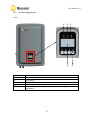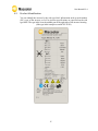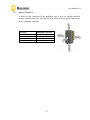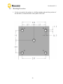
1
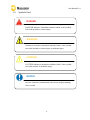
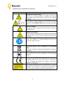
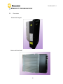
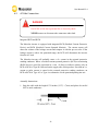
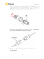
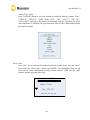
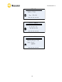
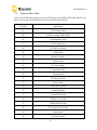
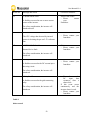
User Manual V1.4 INDEX Index ........................................................................................................................................................................................ 1 1. 2. 3. 4. 5. 6. Notes on this manual ...................................................................................................................................... 3 1.1 Scope of Validation ................................................................................................................... 3 1.2 Symbols Used ............................................................................................................................ 4 1.3 Target Group ............................................................................................................................. 5 Preparation ............................................................................................................................................................ 6 2.1 System Demonstration .............................................................................................................. 6 2.2 Safety Instructions..................................................................................................................... 7 2.3 Explanations of Symbols on Inverter......................................................................................... 9 Product Information.................................................................................................................................... 10 3.1 Overview ................................................................................................................................. 10 3.2 Major Characteristics .............................................................................................................. 11 3.3 Datasheet ................................................................................................................................ 12 Unpacking............................................................................................................................................................. 13 4.1 Assembly parts ........................................................................................................................ 13 4.2 Product Appearance................................................................................................................ 15 4.3 Product Identification ............................................................................................................. 17 4.4 Quality Certificate Card ........................................................................................................... 18 4.5 Further Information ................................................................................................................ 18 Installation........................................................................................................................................................... 19 5.1 Safety....................................................................................................................................... 19 5.2 Mounting Instructions ............................................................................................................. 20 5.3 Safety Clearance ...................................................................................................................... 21 5.4 Mounting Procedure ............................................................................................................... 22 5.5 Safety Lock .............................................................................................................................. 25 5.6 Check Varistors ........................................................................................................................ 27 Electrical Connection .................................................................................................................................. 29 6.1 Safety....................................................................................................................................... 29 1 User Manual V1.4 6.2 Overview of Connection Area ................................................................................................. 30 6.3 AC Side Connection ................................................................................................................. 31 6.4 DC Side Connection ................................................................................................................. 34 6.5 DC Side Disconnection............................................................................................................. 38 6.6 Communication and Monitoring Device ................................................................................. 39 6.7 Software updating ................................................................................................................... 39 Configuration..................................................................................................................................................... 41 7. 7.1 LCD Display .............................................................................................................................. 41 7.2 Setup ....................................................................................................................................... 43 7.3 Event number table ................................................................................................................. 50 7.4 Further information for the event record ............................................................................... 51 8. Recycling and Disposal .............................................................................................................................. 57 Guaranty Scope and Guaranty Service.......................................................................................... 58 9. 9.1 Macsolar Factory Guaranty Scope .......................................................................................... 58 9.2 Guaranty Conditions ............................................................................................................... 58 9.3 Guaranty Exclusion .................................................................................................................. 59 10. Contact ................................................................................................................................................................ 60 Abbreviation................................................................................................................................................................. 61 2 User Manual V1.4 1. NOTES ON THIS MANUAL 1.1 Scope of Validation The main purpose of this User’s Manual is to provide instructions and detailed procedures for installing, operating, maintaining, and troubleshooting the following Macsolar Grid Tie Solar Inverter: MCS2-TL1.5K MCS2-TL2K Please keep this manual all time available in case of emergency. All the illustrated pictures in this Manual concerning Macsolar Grid Tie Solar Inverter derive from the simulated model of MCS2-TL2K. In the event that dimensions and parameter of products have varied, please take the latest document as standard. Further notification will not be issued. 3 User Manual V1.4 1.2 Symbols Used DANGER DANGER indicates a hazardous situation which, if not avoided, will result in death or serious injury. WARNING WARNING indicates a hazardous situation which, if not avoided, can result in death or serious injury or moderate injury. CAUTION CAUTION indicates a hazardous condition which, if not avoided, can result in minor or moderate injury. or moderate injury. NOTICE NOTICE indicates a situation that can result in property damage, if not avoided. 4 User Manual V1.4 1.3 Target Group Chapter 1, 2, 3, 4, 7, 8, 9, 10 and Chapter 11 are intended for anyone who is intended to use Macsolar Grid Tie Solar Inverter. Before any further action, the operators must first read all safety regulations and be aware of the potential danger to operate highvoltage devices. Operators must also have a complete understanding of this device’s features and functions. WARNING Do not use this product unless it has been successfully installed by qualified personnel in accordance with the instructions in Chapter 5, “Installation”. Chapter 5, and Chapter 6 are only for qualified personnel who is intended to install or uninstall the Macsolar Grid Tie Solar Inverter. NOTICE Hereby qualified personnel means he/she has the professional training, knowledge, and experience in: • Installing electrical equipment and PV power systems (up to 1000 V). • Applying all applicable installation codes. • Analyzing and reducing the hazards involved in performing electrical work. • Selecting and using Personal Protective Equipment (PPE). All installation, commissioning, maintenance, repair and recycling of Macsolar Inverter must be done only by qualified personnel. 5 User Manual V1.4 2.PREPARATION 2.1 System Demonstration Solar energy generation systems, based on photovoltaic modules, nowadays represent the most suitable solution, in particular for domestic power levels, to reduce the energy consumption produced by oil and gas. Moreover in different European countries, electricity companies are providing money incentives for the energy produced by renewable sources and injected into the utility grid. The solar inverter is a critical component in a solar energy system. It performs the conversion of the variable DC output of the PV modules into a clean sinusoidal 50 or 60 Hz AC current that is then applied directly to the commercial electrical grid or to a local grid electrical network. Typically, communications capability is included so users can monitor the inverter and report on power and operating conditions, provide firmware updates and control the inverter grid connection. Depending on the grid infrastructure wired (RS-485, CAN, Power Line Communication, Ethernet) or wireless (Bluetooth, ZigBee/IEEE802.15.4, 6LoWPAN) networking options can be used. 6 User Manual V1.4 2.2 Safety Instructions DANGER DANGER due to electrical shock and high voltage DO NOT touch the operating component of the inverter, it might result in burning or death. TO prevent risk of electric shock during installation and maintenance,please make sure that all AC and DC terminals are plugged out. DO NOT touch the surface of the inverter while the housing is wet, it might lead to electrical shock. DO NOT stay close to the instruments while there are severe weather conditions including storm, lighting, and etc. WARNING The installation,service ,recycling and disposal of the inverters must be performed by qualified personnel only in compliance with national and local standards and regulations. Please contact your dealer to get the information of authorized repair facility for any maintenance or repairmen. Any unauthorized actions including modification of product functionality of any form will affect the validation of warranty service, Macsolar may deny the obligation of warranty service accordingly. 7 User Manual V1.4 CAUTION The PV inverter will become hot during operation,please don’t touch the heat sink or peripheral surface during or shortly after operation。 Risk of damage due to improper modifications. Never modify the inverter or other components of the system. NOTICE Public utility only The PV inverter designed to feed AC power directly to the public utility power grid,do not connect AC output of the device to any private AC equipment. Before the inverter is connected to the grid, official written approval from the local bureau of power should be obtained. 8 User Manual V1.4 2.3 Explanations of Symbols on Inverter Symbol Description Dangerous electrical voltage This device is directly connected to public grid, thus all work to the inverter shall only be carried out by qualified personnel. DANGER to life due to high electrical voltage! There might be residual currents in inverter because of large capacitors. Wait 10 MINUTES before you remove the front lid. NOTICE, danger! This device directly connected with electricity generators and public grid. Danger of hot surface The components inside the inverter will release a log of heat during operation, DO NOT touch aluminum housing during operating. A record has occurred Please go to Chapter 7.4 “Further information for the event record” to remedy the record. This device SHALL NOT be disposed of in residential waste Please go to Chapter 8 “Recycling and Disposal” for proper treatments. Without Transformer This inverter does not use transformer for the isolation function. CE Mark Equipment with the CE mark fulfils the basic requirements of the Guideline Governing Low-Voltage and Electromagnetic Compatibility. No unauthorized perforations or modifications Any unauthorized perforations or modifications are strictly forbidden, if any defect or damage (device/person) is occurred, Macsolar shall not take any responsibility for it. 9 User Manual V1.4 3. PRODUCT INFORMATION 3.1 Overview Industrial Layout Reduced Heat Sink 10 User Manual V1.4 3.2 Major Characteristics Macsolar inverter has following characteristics which make Macsolar inverter “High Efficiency, High Reliability, High Cost Effective Ratio” • High DC input voltage, can be connected with more PV panels. • Wide MPPT voltage range can fit in different locations or various weather conditions. • High MPP tracking accuracy, catch most of electricity from panels and converts it into money in your pocket. • Complete set of protection methods. Also, following protection methods are integrated in Macsolar inverter: • • • • • • Internal overvoltage DC insulation monitoring Ground fault protection Grid monitoring Ground fault current monitoring DC current Injection monitoring 11 User Manual V1.4 3.3 Datasheet Type MCS2-TL1.5K MCS2-TL2K Max. DC Power [W] 1800 2400 Rated DC Power [W] 1600 Input (DC) 2100 Absolute DC Voltage [V] 480 MPPT DC Voltage Range[V] 125-480 Standby Voltage [V] 130 Stop Voltage[V] 100 Activation Voltage[V] 150 Rated DC Voltage[V] 360 Max. Input Current [A] 12 Number of DC Connection Sets 1 12 2 Number of MPP Trackers 1 DC Connection Amphenol Helios 4 DC Switch Optional Output (AC) Rated AC Power [W] 1500 2000 Max. AC Power [W] 1650 2200 Rated AC Current [A] 6.5 8.7 Max. AC Current [A] 8.5 11.0 Grid Voltage/Frequency Range According to VDE 0126-1-1, RD1663, ENEL guide-2010,G83,AS4777,C10/11 Power Factor(cosΦ) >0.99(full load) AC Current Distortion (THD) < 3% AC Connection WIELAND 96-032-5054-3 Efficiency Max. Efficiency 97.2% 97.2% Euro Efficiency (at 360Vdc) 96.6% 96.6% MPPT Accuracy(static) 99.5% 99.5% Protection Internal Overvoltage Protection Yes DC Insulation Monitoring Yes DC/AC Side Varistors Yes Direct Current Monitoring Yes Ground Fault Current Monitoring Yes Grid Monitoring Yes Short Current Protection Yes Thermal Derating Protection Yes Interface LCD Display 128x64 Pixels,Backlight Display Language Datalogger & Communication Multi Languages RS485A,USB,RS485B(Optional),Ethernet(Optional) Other Data Isolation Transformerless Operating Temperature Range -20ºC to +60ºC Cooling Method Ambient Humidity Natural Convection 0% to 98% Non-condensing Noise Emission [dBA] <40 Operation Altitude[m] <2000 Consumption during Night[W] <0.1 IP Protection IP65 Dimensions (WxHxD) [mm] 507 x 350 x 159 Weight[kg] 11.7 Standard Warranty [Year] 5 / 10 (Optional) Safety Class Compliance EMC Compliance Grid Protection Compliance AS3100, IEC62109 EN61000-6-2,EN61000-6-3, EN61000-3-2,EN61000-3-3,EN61000-3-11,EN61000-3-12 According to VDE 0126-1-1, RD1663,G83,AS4777,C10/11, ENEL guide-2010 12 User Manual V1.4 4. UNPACKING 4.1 Assembly parts After you receive the Macsolar inverter, please check if there is any damage on the carton. Also, please check the inside completeness and for any visible external damage on the inverter or any accessories. Contact your dealer if anything is damaged or missing. 13 User Manual V1.4 Object A A1 B C Part No. 40005000030 40005000040 212000015 20605000030 D E F G H 206020002 206030004 20400000030 21000000010 20410000030 Quantity 1 1 1 2 sets for 2k or 1 set for 1.5k 1 1 5 5 1 I J K L M 206000001 204090001 22000000122 21901000050 20603000020 1 5 1 1 1 Description Inverter MCS2-TL1.5K Inverter MCS2-TL2K Rear panel DC connector AC connector RJ45 connector ST6×50 Expansion screw Expansion tube M6×12 cross recessed pan head screw and washer connecting the rear panel with inverter Ring tool to disconnect DC connector Washer Ф 6 Installation guide, including user manual Quality certificate card USB connection cable (Male-Male) 14 User Manual V1.4 4.2 Product Appearance Front: A B D Object A B C D E C E Description LED- POWER LED-RUN LED-FAULT LCD screen for checking the operating status and configuration Capacitive touch-sensing buttons for displays and configuration of parameters 15 User Manual V1.4 Bottom: G A B C D E Object Description A B DC input (1 set for MCS2-TL1.5K and 2 sets for MCS2-TL2K) Plugs for connecting the RS485 communication module. Among them COM1 must be equipped, but COM2 is optional equipped (Customized) USB plug for connecting the inverter to a PC directly via USB connection AC output Heat sink Extra lock DC switch to turn off the inverter manually (Optional, not Must) C D E F G 16 F User Manual V1.4 4.3 Product Identification You can identify the inverter by the side type label. Information such as serial number (SN.), type of the inverter, as well as inverter specifications are specified on the side type label. The type label is on the middle part of the right side of the inverter housing. (Side type label example as on MCS2-TL2K) 17 User Manual V1.4 4.4 Quality Certificate Card When the single product passes a series of performance tests as well as visual inspection of all surfaces, a quality certificate card, which represents the outcome of internal inspection, will be issued by Macsolar’s quality assurance department rather than by the third party (authoritative laboratory or testing institute). With this card we want to convince our clients that Macsolar puts a new premium on the quality of products. 4.5 Further Information If you have any further questions concerning the type of accessories or installation, please check our website www.macsolar-power.com or contact our service hotline. 18 User Manual V1.4 5. INSTALLATION 5.1 Safety DANGER DANGER to life due to potential fire or electricity shock. DO NOT install the inverter near any inflammable or explosive items. This inverter will be directly connected with HIGH VOLTAGE power generation device, the installation must be performed by qualified personnel only in compliance with national and local standards and regulations. NOTICE NOTICE due to the inappropriate or the harmonized installation environment may jeopardize the life span of the inverter. Installation directly expose under intensive sunshine is not recommended. The installation site MUST have good ventilation condition. 19 User Manual V1.4 5.2 • • • • • • • • • • • Mounting Instructions Macsolar inverter is designed for installation both indoors and outdoors Please only mount the inverter in the direction as illustrated above Installation of the inverter in the vertical direction is recommended Tilted backwards by max.15 degree is allowed Never install the device with a forward tilt, horizontally or even upside down For the convenience of checking the LCD display and possible maintenance activities, please install the inverter at eye level Make sure the wall you selected is strong enough to handle the screws and the weight of the inverter Ensure the device is properly fixed to the rear panel It is not recommended to install the inverter directly exposed in strong sunshine, the excess heating might lead to power reduction The ambient temperature of installation site should be between -20 °C and +40 °C ( between -4 °F and 104 °F ) Make sure the ventilation of the installation spot, not sufficient ventilation may affect the operating performance of the electronic components inside the inverter and the life span of the inverter might be jeopardized 20 User Manual V1.4 5.3 Safety Clearance To make sure the ventilation of the installation spot, if there are multiple Macsolar inverters installed in the same area, the following safety clearance shall be followed for proper ventilation conditions. Direction Above Below Side Front Minimum Clearance 30 cm 50 cm 30 cm 5 cm 21 User Manual V1.4 5.4 Mounting Procedure 1. Use the rear panel in the package as a drilling template and mark the positions of the drill holes, as illustrated below with symbols A/B/C/D/E. A B C D E 22 User Manual V1.4 2. According to the marks, drill 5 holes in the wall (in conformity with position A/B/C/D/E marked in above picture), and then place five expansion tubes in the holes using a rubber hammer. 3. Mount the rear panel. Wring five screws into the expansion tubes and tightly mount the rear panel on the wall. 23 User Manual V1.4 4. Carefully attach the inverter to the rear panel according to the position of the screws. Make sure the backside of the inverter is closely against the rear panel. When two people transport the inverter, make sure each one use the hand grip in right position. Notch 5. Pay attention to the four notches cut in both flanks of heat sink (as illustrated in above picture), which should be placed in corresponding hooks from the rear panel. Make sure that the heat sink and the rear panel are buckled together and the inverter is tightly attached to the rear panel. 6. Please carefully check the accessories and original carton to make sure during the installation every necessary part is used and nothing is missing. 24 User Manual V1.4 5.5 Safety Lock To prevent possible theft activity, Macsolar gives you an extra guard for your property. It is possible to lock the inverter to the rear panel with a padlock. The diameter of this hole drilled at the padlock location is 7mm. Recommended padlock dimension: A B C 5 mm A.Shackle Diameter 8~15 mm B.Vertical Clearance C.Horizontal Clearance 12~20 mm Stainless, solid hanger and secured lock cylinder 25 User Manual V1.4 NOTICE For further maintenance and possible repair, please keep the key of the padlock in a safe place. 26 User Manual V1.4 5.6 Check Varistors If the one or more of the varistors might be out of function, please check or replace the varistors according to following steps: 1. Loosen all 6 captive screws of the upper lid. Right after the 6 captive screws are removed, please keep them at a distance. Lift the lid upwards and remove it. 2. Then you will see the 5 varistors in 2 groups: 2 in left side and 3 in right side. 27 User Manual V1.4 3. Remove and install the varistors Remove: First use specified tool and insert it to three holes in the left side of the varistor, then press it to the end. Pull the varistor out. Install: Use specified tool and insert it to three holes in the left side of the varistor, then press it to the end. Press the varistor in. 4. Put the lid back and re-screw all 6 screws, make sure the lid is tightened to the inverter. 28 User Manual V1.4 6. ELECTRICAL CONNECTION 6.1 Safety DANGER DANGER to life due to potential fire or electricity shock. With the inverter powered, comply with all prevailing national regulations on accidents prevention. This inverter will be directly connected with HIGH VOLTAGE power generation device, the installation must be performed by qualified personnel only in compliance with national and local standards and regulations. NOTICE Electrical connections shall be carried out in accordance with the applicable regulations, such as conductor sections, fuses, PE connection. 29 User Manual V1.4 6.2 Overview of Connection Area Bottom: G A B C D E Object Description A B DC input (1 set for MCS2-TL1.5K and 2 sets for MCS2-TL2K) Plugs for connecting the RS485 communication module. Among them COM1 must be equipped, but COM2 is optional equipped (Customized) USB plug for connecting the inverter to a PC directly via USB connection AC output Heat sink Extra lock DC switch to turn off the inverter manually (Optional, not Must) C D E F G 30 F User Manual V1.4 6.3 AC Side Connection DANGER DANGER to life due to potential fire or electricity shock. NEVER connect or disconnect the connectors under load. Integrated RCD and RCM The Macsolar inverter is equipped with integrated RCD (Residual Current Protective Device) and RCM (Residual Current Operated Monitor). The current sensor will detect the volume of the leakage current and compare it with the pre-set value. If the leakage current is above the permitted range, the RCD will disconnect the inverter from the AC load. The Macsolar inverter will probably cause a d.c. current in the external protective earthing conductor. Where a residual current-operated protective (RCD) or monitoring (RCM) device is used for protection in a case of direct or indirect contact, only an RCD or RCM of Type B is allowed on the supply side of this product. Provided an a.c. current or pulse current is caused in the external protective earthing conductor, an RCD or RCM of Type AC or Type A as alternative can be permitted putting into use. Assembly Instructions: 1. Strip the cable with the length 0.276 inches (9/32”) - (7mm) and please be careful NOT to nick conductors. 31 User Manual V1.4 2. Screw off and separate each component of AC connector as follows. 3. Pass the cable through each component from left to the right as follows. 4. Use a screw driver and loose the three screws at the side of the straight plug. Then insert the stripped N, L and PE cable accordingly to the corresponding position and fully tighten the screws. 32 User Manual V1.4 5. Aim the terminals on the straight plug to the holes of the grommet, and then compress them together. It is recommended to use the AC connection cable wrapping three stranded conductors (circled part in picture below), whose performance is qualified to pass the insulation as well as Hi-Pot tests. 6. Finally, connect the straight plug to the AC terminal on inverter. Pay attention to the polarity of the terminals to avoid wrong connecting. AC output terminal from the inverter 7. The diameter of DC and AC cable should be featured with sufficient currentcarrying capability. 33 User Manual V1.4 6.4 DC Side Connection For MCS2-TL2K, there is only one MPP Tracker, for the two string inputs, the connected PV modules must meet following requirements: Same type Same quantity Identical alignment Identical tilt Inverter Type MCS2-TL1.5K MCS2-TL2K MPP Tracker 1 1 Max. DC Power Max. DC Voltage 1800W 2400W 480V Max. DC Current 12A 12A DANGER DANGER to life due to potential fire or electricity shock. NEVER connect or disconnect the connectors under load. NOTICE If only one string input is used for DC connection, please use the sealing plug to seal the left DC input set to ensure the inverter IP 65 protection. 34 User Manual V1.4 The DC connectors come pre-assembled and the caps are loose. The whole connector will include the male side and female side as showed below: Female side connector (F) Male side connector (M) Assembly Instructions: 1. Strip the cable with the length 0.276 inches (9/32”) - (7mm) and please be careful NOT to nick conductors. Use specified strip tool in this step. Adjust the striper stopper and put the cable in corresponding notch to strip the length of 7mm. Please see below figures. 35 User Manual V1.4 2. Insert striped cable into contact barrel and insure all conductor strands are captured in the contact barrel and the conductors are visible in the contact barrel observation hole. Please see below figures. Barrel observation hole Conductor should be visible Barrel observation hole Conductor should be visible 3. Crimp contact barrel by using the hex crimping die. Please see below figures. Cable requirements: Cable Size 2.5 mm2 4 mm2 6 mm2 Cable pull-out force requirement Min. 310 N (70 Lbs) Min. 400 N (90 Lbs) Min. 450 N (100 Lbs) 36 User Manual V1.4 4. Insert contact cable assembly into back of male and female connector. A “click” should be heard or felt when the contact cable assembly is seated correctly. Please see below figures. Female side connector (F) Male side connector (F) 5. Wrest the cap by using the torque of 2.6~2.9NM. 6. After wrest the cap tightly, align the 2 half connectors and mate them together by hand until a “click” is heard or felt. 37 User Manual V1.4 6.5 DC Side Disconnection When the separation of DC connectors is necessary, please use the specified tool (Ring tool or wrench tool) to separate them. While using the ring tool or wrench tool, please make sure the wedge side of the fingers faces the female connector and push the tool down. Then separate the connector by hand. See below figures. Separation by ring tool Separation by wrench tool 38 User Manual V1.4 6.6 Communication and Monitoring Device There are 3 plugs in the bottom side of the Macsolar inverter: 1 × USB 1 × RS485---COM1 1 × RS485---COM2 (Optional) All communication and monitoring plugs in inverter are simply “plug and use”. Please select the appropriate one according to the desired functionality and usage. 6.7 Software updating Please pay attention to the USB plug mentioned in last section, which is prepared for software updating. By this means we can supplement new developed functions or just modify and remove the non-used function to inverters with ease on the basis of previous software version. Connection of relevant parts via USB cable as follows, whose terminals are both male. 39 User Manual V1.4 After building the hardware circuit for inverter’s software updating, we should carry out the following procedures: 1. Install the application program Macsolar-Power InverterSoftware V2.0 on your PC 2. Open the software Macsolar-Power InverterSoftware V2.0. You will see the interface as below. Select the file which needs to be updated or enter the route of this file. 3. Select the proper Update Type. Then you can start the software updating. Through the “Status” text box you can monitor the whole updating process. 40 User Manual V1.4 7. CONFIGURATION 7.1 LCD Display A B D Object A B C D E C E Description LED-POWER LED-RUN LED-FAULT LCD screen for checking the operating status and configuration Capacitive touch-sensing buttons for displays and configuration of parameters Press any button to illuminate the LCD screen. 41 User Manual V1.4 Item ESC ENTER Function Depending on the selection: To cancel operation To navigate to the previous level menu Depending on the selection: To navigate up Change to the previous number Depending on the selection: To navigate down Change to the next number Depending on the selection: To confirm a selection To navigate to the next level menu NOTICE Macsolar inverter is not an aligned measuring instrument for current, voltage or power consumption. A slight deviation of a few percent points is intrinsic to the system, the results from the inverter cannot be used for grid balance calculations. An aligned meter will be required to make calculations for the utility company. 42 User Manual V1.4 7.2 Setup DISPLAY After the inverter has started, programs will be initialized with the screen showing as follows; Macsolar-Power Initialize... xxx-xx-xx xx:xx 43 User Manual V1.4 Now in this interface you can check all necessary information about the system; After reviewing all information relevant to the system, you are able to enter the main menu by pressing the “Enter” button on display panel and acquire any parameter concerning the product which interests you, such as yield power, record info. etc. Yield Power Select “Yield Power” option to enter the submenu and the cumulated power generation by Day will be presented on the screen; Yield Power Today: 0.08KWh Total: 0.16KWh xxx-xx-xx xx:xx 44 User Manual V1.4 Actual Value Press “ESC” key to exit from the submenu and back to main menu. Press the “down” key to select the “Actual Value” option with “ENTER” for confirmation. Subsequently, you have the free choice to check the actual value from the corresponding objects PV string1 or AC through operation of “up” and “down” button. Record Info. Press “ESC” key to exit from the submenu and back to main menu. Press the “down” key to select the “Record Info.” option with “ENTER” for confirmation. You are able to check all record information generated at different moments during the running of inverter. The complete record information including Record code. and definition are summarized in section 7.3. You can also learn about the specific record description according to the corresponding event No. by referring to chapter 7.4 “Further information for the event record”. 45 User Manual V1.4 History Info. Press “ESC” key to exit from the submenu and back to main menu. Press the “down” key to select the “History Info.” option with “ENTER” for confirmation. By virtue of the displayed graphic diagram you can check the power generation last 7 days. Configuration Press “ESC” button to exit from the submenu and back to main menu. Press the “down” key to select the “Configuration” option with “ENTER” for confirmation. Subsequently, you are eligible to set up the “Language”, “Date/Time”, “Address”, “Safe Type” through manipulation of “up” and “down” button. “Language” Setup: 46 User Manual V1.4 Set Language English xxx-xx-xx xx:xx “Date/Time” Setup: Use “Up/Down” key to set the number and confirm the settings by “ENTER” button; Set Date&Time 2010-12-23 15:12:12 xxx-xx-xx xx:xx “Address” Setup: Use “Up/Down” key to set the number and confirm the settings by “ENTER” button; NOTICE Possible communication failure due to wrong configuration Selection of the inverter’s address will directly affect the performance of the data logger. 47 User Manual V1.4 “Safety Type” Setup: Press “Up/Down” button to select the authorized certificate from the options “None”, “VDE0126”, “RD1663”, “ENEL Guide 2010”, “GB”, “AS4777”, “UK G83”, “C10/11:2009” applying to the product in conformity with the regulations for safety class compliance or suitability for grid connection of the inverter. Please careful operate, don't arbitrary change! Device Info. Press “ESC” key to exit from the submenu and back to main menu. Press the “down” key to select the “Device Info.” option with “ENTER” for confirmation. Then you can get access to system information involving control software, ARM software, serial number, machine type and safety type. Control S/W Update Time: Ver: V01.00 xxx-xx-xx xx:xx 48 User Manual V1.4 ARM S/W Update Time: Ver: V01.00 xxx-xx-xx xx:xx Serial Number 11-45-45-3434-34-45-45 xxx-xx-xx xx:xx Machine&Safe MachineType:1.5K Safe Type: AS4777 xxx-xx-xx xx:xx 49 User Manual V1.4 7.3 Event number table If any of the following messages occurs in LCD Screen, or the status LED Light “Fault” is on, there is one or more event that has been detected by Macsolar Inverter. Event NO. Information 0 Grid Voltage Fault 01 Grid Overvoltage.10min Fault 02 Grid Frequency Fault 03 Grid Voltage Loss 04 DC Bus Overvoltage 05 GFCI Fault 06 Inverter Overheat 07 Varistor Fault 08 PV Overvoltage 09 Consistence Fault 10 Isolation Fault 11 DC Injection Fault 12 Device Fault 13 GFCI Device Fault 14 Comm.Disturbed 15 Current Sensor Fault 16 CPU Ref 2.5V Fault 17 EEPROM R/W Fault 18 DC Injection Device Fault 19 Relay Fault 20 AC Over Current 50 User Manual V1.4 7.4 Further information for the event record Table 1 Record originated from inverter fault Event No. Message and course Corrective measures 10 “Isolation Fault” Check the isolation of the PV panel. If this event occurs continuously and the inverter doesn’t work: Please contact your franchiser. The isolation resistance between the DC side to earth is too low. Following conditions might lead to this error: The isolation of the PV panel is not so good. Internal fault of the inverter. The inverter will not feed power to the grid when this event occurs. 12 “Device Fault” A fault has occurred in one or more major components of the inverter. If this event occurs: Please contact your franchiser. For safety consideration, the inverter will shutdown. 13 “GFCI Device Fault” A fault has occurred to the GFCI detecting circuit. If this event occurs: Please contact your franchiser. For safety consideration, the inverter will shutdown. 14 “Comm. Disturbed” A fault has occurred in the internal communication of the inverter. For safety consideration, the inverter will shutdown. 51 If this event occurs: Please contact your franchiser. User Manual V1.4 Event No. Message and course Corrective measures 15 “Current Sensor Fault” If this event occurs: Please contact your Franchiser. A fault has occurred in one or more current sensor of the inverter. For safety consideration, the inverter will shutdown itself. 16 “CPU Ref 2.5V Fault” The CPU voltage that detected by internal sensor is deviating the pre-set 2.5V reference line. 17 “EEPROM R/W Fault” If this event occurs: Please contact your franchiser. If this event occurs: Please contact your franchiser. Internal device fault. For safety consideration, the inverter will shutdown . 18 “DC Injection Device Fault” A fault has occurred to the DC current inject detecting circuit. If this event occurs: Please contact your franchiser. For safety consideration, the inverter will shutdown . 19 “Relay Fault” A fault has occurred to the grid-connecting relay. For safety consideration, the inverter will shutdown. Table 2 Other record 52 Please disconnect the DC input then reconnect after a short while. If this event occurs continuously and the inverter doesn’t work: Please contact your franchiser. User Manual V1.4 Event No. Message and course Corrective measures 0 “Grid Voltage Fault” Check the grid voltage. If this event occurs continuously and the inverter doesn’t work: Please contact your franchiser. The grid voltage has exceeded the permitted range according to local gird regulations. Following conditions might lead to this error: Grid voltage is out of the range rating. Sudden change to the grid. Grid impedance at the terminal of the inverter is too high. For safety consideration, the inverter will disconnect from the grid for a short time till the grid return to normal. 01 “Grid Overvoltage 10min Fault” The average gird voltage in 10 minutes has exceeded the permitted range according to local gird regulations. Following condition might lead to this error: Check the grid voltage. If this event occurs continuously and the inverter doesn’t work: Please contact your franchiser. Grid voltage is too high. For safety consideration, the inverter will disconnect from the grid for a short time till the grid return to normal. 02 “Grid Frequency Fault” The grid voltage has exceeded the permitted range according to local gird regulations. Following conditions might lead to this error: Grid frequency is out of the range rating. Sudden change to the grid.. Incorrect safety guide setting. For safety consideration, the inverter will disconnect from the grid for a short time till the grid return to normal. 53 If this event occurs continuously and the inverter doesn’t work: Please contact your franchiser. User Manual V1.4 Event No. Message and course Corrective measures 03 “Grid Voltage Loss” Check AC installation. Check network connection. Check fuse. If this event occurs continuously and the inverter doesn’t work: The inverter has detected an error in the cabling and cannot connect to the grid. Following conditions might lead to this error: Network connection installation is inappropriate. Cabling inappropriate. Grid power-off. AC output fuse open. Event 0 and event 2 may be reported additionally. 04 “DC Bus Overvoltage” The voltage of the DC Bus is too high. Following conditions might lead to this error: The input voltage of the PV string is too high. The DC to DC function is out of control. For safety consideration, the inverter will disconnects itself from the grid. 05 “GFCI Fault” The inverter has detected a ground fault in the PV system. 54 Please contact your franchiser. Please immediately disconnect the inverter from the PV strings (see chapter 6.5 “DC side Disconnection”). Measure the DC voltage of the strings to find out whether the value is in the range of specified DC voltage from datasheet. If the voltage is still too high, please make consultation with the system installer. Otherwise, please contact your franchiser. Please refer to the PV system installer to renovate the ground fault. If this event occurs continuously and the inverter doesn’t work: Please contact your franchiser. User Manual V1.4 Event No. Message and course Corrective measures 06 “Inverter Overheat” Please ensure sufficient ventilation. If this event occurs continuously and the inverter doesn’t work: The temperature of the heat sink is too high. Following conditions might lead to this error: Sensor of the temperature defective. Overheating inside. Not sufficient ventilation. For safety consideration, the inverter will disconnect from the grid until the temperature return to normal. 07 “Varistor Fault” The open-circuit voltage of the PV generator is higher than the maximum DC input voltage of the inverter. Sudden DC surge. Junction temperature of solar panel too low. Event 8 may be reported additionally. If this event occurs: Please check the varistors as chapter 5.6 “Check Varistors”. If this error is not solvable: please contact your franchiser. Please immediately disconnect the inverter from the PV strings (see chapter 6.5 “DC side Disconnection”) . Check the DC voltage of the strings for adherence to the maximum input voltage of the inverter, before you reconnect the inverter to the PV strings. “Consistence Fault” If The varistor on the DC side is defected. Following conditions might lead to this error: Varistor is burst due to high voltage surge such as thunder lightning. Varistor is ageing invalid 08 “PV Overvoltage” The DC input voltage which connects to the inverter is too high. Following conditions might lead to this error: 09 Please contact your franchiser. Internal fault has occurred for the inverter. 55 this event occurs continuously and the inverter doesn’t work: Please contact your franchiser. User Manual V1.4 Event No. Message and course Corrective measures 11 “DC Injection Fault” If this event occurs continuously and the inverter doesn’t work: The direct current injecting to the grid exceeds the permitted range. Following conditions might lead to this error: Sudden input power change due to cloud. Internal fault of the inverter. “AC Over Current” 20 The detected AC current has exceeded the preset Max. AC Current. Following causes might lead to this error: Short circuit happens in the grid. Please contact your franchiser. Check the AC network to find out the short circuit,then restart the inverter manually. If this event occurs continuously and the inverter doesn’t work: Please contact your franchiser. Table 3 Explanation of fault grades Fault gra- Description des A Inverter is stopped due to equipment fault. Power Run Fault (Green (Yellow (Red LED) LED) LED) 10,12,13,1 On Off restorable faults and On Off environment faults. Not fault, suggestive C display. Inverter can On 4,15,16,17, 18,19 Inverter is stopped due to B Event No. On works normally. 56 On Flash (1Hz) Flash (1Hz) 0,01,02,03, 04,05,06,0 8,09,11,20 07 User Manual V1.4 8. RECYCLING AND DISPOSAL WARNING This device SHALL NOT be disposed of in residential waste. To comply with European Directive 2002/96/EC on waste Electrical and Electronic Equipment and its implementation as national law, electrical equipment that has reached the end of its life must be collected separately and returned to an approved recycling facility. Any device that you no longer required must be returned to your dealer or you must fine an approved collection and recycling facility in your area. Ignoring this EU Directive may have severe affects on the environment and your health. 57 User Manual V1.4 9. GUARANTY SCOPE AND GUARANTY SERVICE 9.1 Macsolar Factory Guaranty Scope This guaranty declaration is solely applied to the following Macsolar Grid Tie Solar Inverter: MCS2-TL1.5K MCS2-TL2K For the above named products, you will receive a Macsolar factory warranty card which will valid for 5 years from the date of purchase. The Macsolar factory warranty covers any costs which you incur for repair or replacement parts during the agreed period beginning at the date of purchase of the device, subject to the conditions listed below. This is not associated with a durability warranty. You have the possibility of purchasing an extension of this Macsolar factory warranty within the 5 year term of the Macsolar factory warranty. The prices are based on the respective Macsolar price list valid at the time the warranty extension was signed. 9.2 Guaranty Conditions This guaranty declaration is solely applied when any defect of Macsolar inverter is detected. If a device becomes defective during the Macsolar guaranty period, and it is proved that further functional performance is impossible, the device will be, as selected by Macsolar: Repair the defect at the factory free of charge within the guaranty period. Exchange for a replacement device of equivalent value according to model and age. If it is the latter case, the remainder of the warranty entitlement will be automatically transferred to the replacement device. In this case, you will not receive a new certificate since your entitlement is already documented at Macsolar if the rest warranty period is more than 1 year. If a replacement occurs when rest warranty period is less than 1 year, it will automatically extend the rest warranty period to exactly 1 year. 58 User Manual V1.4 NOTICE If exchange for a replacement device of equivalent value according to model and age is needed. The defected unit must, where possible, be returned in its original or equivalent packaging. Macsolar will only perform guaranty service only if the user provides a copy of invoice which was issued to the user by the dealer and a completed warranty card. If any one of these two is missing, Macsolar has the rights to deny the guaranty service or only provide paid service. 9.3 Guaranty Exclusion Guaranty declaration is excluded in the following cases: Transport damage Improper installation and installation that does not comply with standards Use of the devices in ways not intended Improper operations without following the user manual Operation of units with defective protective equipment which might lead to damage Unauthorized modifications to the units or repair attempts Influence of foreign objects and force majeure (lightning, grid overvoltage, severe weather, fire) Insufficient ventilation of the unit Failure to observe the relevant safety regulations If the device becomes defective when in any of the above cases, Macsolar will not perform guaranty service and the user shall take whole responsibility for the defects. 59 User Manual V1.4 10. CONTACT Shanghai Headquarter Building 9, No.590 Ruiqing Road CN-201201 Shanghai P.R. China Tel: (+86)-21-50720833 / (+86)-21-68689998 Fax: (+86)-21-50720639 Email: [email protected] www.macsolar-power.com Serviceline Tel: (+86)-21-50720833 / (+86)-21-68689998 Fax: (+86)-21-50720639 Email: [email protected] www.macsolar-power.com 60 User Manual V1.4 ABBREVIATION LCD LED MPPT PV GFCI Vdc Vac Vmpp Impp Voc Isc AC DC VDE 0126-1-1 UL 1741 Liquid Crystal Display Light Emitting Diode Maximum Power Point Tracking Photovoltaic Ground Fault Circuit Interrupter Voltage at the DC side Voltage at the AC side Voltage at the Maximum Power Point Amperage at Maximum Power Point Open Circuit Voltage Short Circuit Current Alternating Current ( Form of electricity supplied by Utility Company ) Direct Current ( Form of electricity generated by PV modules ) German standards for establishing suitability for Grid Connection of the Inverter. US standards for establishing suitability for Grid Connection of the Inverter. 61