1
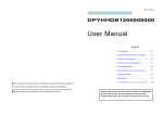
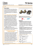
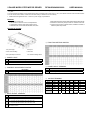
2 PHASE MICRO STEP MOTOR DRIVER
DPYHHDU2420000000
USER MANUAL
• Thanks for purchased our product, Please read this user manual before using the product. Please reserve this user manual for looking up at
any time.
• The environment conditions of surrounding temperature of working area for this unit is 0~+40°C, the relative moisture must be under 85% RH.
• Do not use this unit as water, oil and too much dust nearby or where the sun burn directly.
• Please select the right DC20~40V,above 4A, power supply of specification.
Features
• DC20~40V Power Input.
• Can choose current from 0.5A~4.0A adjustments.
• Overheating protection and signal output function
• Resolution can choose 200,400,500,800,1000,1600
2000,3200,5000,6400,10000,12800,25000,25600,50000,51200
• Automatic current down (ACD) function for reduced motor heat.
• Constant current driving unipolar method, suitable for 6 leads or
8 leads 2-phase step motors.
Function & Contact
◎ FUNCTION SETTING SWITCH
1.for power light
5.for input
2.3.for current setting
6.for motor
4.for input/output connector
7.for function setting switch
◎ POWER LIGHT
Description
PWR When the driver accept DC20~40V, PWR will be light.
ALM When motor current overload , ALM will be light.
◎ CURRENT ADJUSTMENT SWITCH
Description
RUN To set the drive current when motor run (0.5A~4.0A)
◎ POWER INPUT TERMINAL
Description
V+ POWER DC20~40V@4A positive input
V- POWER negative input
◎ MOTOR TERMINAL
A
◎ INPUT SIGNAL TERMINAL
Description
CW 1P:Clock signal input terminal
2P:The pulse input terminal which have the motor CW.
CCW 1P:Direction signal input terminal
2P:The pulse input terminal which have the motor CCW.
COF When add a high voltage in this point, the current of the driver would
down to zero at once.
VEXTA
TAMAGAWA
SANYO
TECO
TECO
6Leads
6Leads
6Leads
6Leads
6Leads
black
black
black
black
red
TECO
8Leads
red
/A
green
green
green
green
red
white
black
B
red
red
red
red
green
/B
blue
blue
blue
blue
green
white
green yellow
CA
yellow
yellow
yellow
yellow
black
CB
white
white
white
white
white
red,white green,white
black,white yellow,white
Signal Specification
Pulse signal is negative level contact is for noise isolation,When pulse from HIGH change LOW,driver will drive the motor one step.
Pulse width above 1μSec.,the changeover interseptal time of H、L is under 20μSec.
Pulse voltage should be with DC4~10V and keep the current under 20mA。Output current of drive should be keep under 20mA,To make sure
photo coupler wasn’t burned。(if vcc 12V, add 1KΩ¼W resistor,if vcc 15V, add 1.5KΩ¼W resistor,if vcc 24V 2KΩ½W resistor)
1P input, when LOW the,motor run with CCW direction, when HIGH the motor run with CW direction.
Specification
Item/Model
Power
Connecting Diagram
2 phase micro step drive / MDC2116
DC20 ~ 40V @ 4A
Drive Method
PWM Constant Current
Drive Current
0.5A ~ 4.0A/PHASE
Can choose:
200、400、500、800、1000、1600、2000、
3200、5000、6400、10000、12800、25000、
25600、50000、51200s/r
Resolution
Control Mode
Max Pulse Speed
1P (Signal-Pulse),2P (Two-Pulse)
800K Hz (above)
Pulse Width
>1μS (Min)
Direction Respond
>20μS (Min)
Input Signal
L: 0~+0.5V,H: +4~+10V, <20mA
Input Signal
220Ω
impedance
Output Signal
(Open Collector),40V, 20mA (Max)
Noise Isolation
Use of Photo Coupler
Temperature
0 ~ +40°C
Moisture
<85%RH
Dimension (mm)
Weight
133.5(L) x 90(W) x 41.5(H)
325g
Dimension (mm)
90
10
41.5
19
133.5
124