1
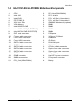
GA-5YXS1-RH/GA-5YXS-RH Xeon® Processor Motherboard USER’S MANUAL Xeon® Processor Motherboard Rev. 1001 * The WEEE marking on the product indicates this product must not be disposed of with user's other household waste and must be handed over to a designated collection point for the recycling of waste electrical and electronic equipment!! * The WEEE marking applies only in European Union's member states. English GA-5YXS1-RH/GA-5YXS-RH Motherboard Table of Content Item Checklist ........................................................................................ 3 Chapter 1 Introduction ............................................................................ 4 1-1 Considerations Prior to Installation ............................................................................ 4 1-2 Features Summary .................................................................................................... 5 1-3 GA-5YXS1-RH/GA-5YXS-RH Motherboard Components ....................................... 7 Chapter 2 Hardware Installation Process .............................................. 9 2-1 Installing Processor and CPU Haet Sink .................................................................. 9 2-1-1: Installing CPU ......................................................................................................... 9 2-1-2: Installing Cooling Fan ........................................................................................... 10 2-2 Install Memory Modules ............................................................................................ 11 2-3 Connect ribbon cables, cabinet wires, and power supply .................................. 13 2-3-1 : I/O Back Panel Introduction ................................................................................ 13 2-4 Connectors Introduction & Jumper Setting ............................................................ 15 2-5 Block Diagram ........................................................................................................... 24 Chapter 3 BIOS Setup .......................................................................... 25 Main ........................................................................................................... 27 Advanced Processor Options ........................................................................................ 29 Advanced ................................................................................................... 31 Memory Configuration ..................................................................................................... 32 PCI Configuration ............................................................................................................. 33 I/O Device Configuration ................................................................................................. 35 Advanced Chipset Control ............................................................................................. 38 Hardware Monitor ............................................................................................................ 39 Security ...................................................................................................... 41 Server ......................................................................................................... 43 System Management ...................................................................................................... 44 Console Redirection ........................................................................................................ 45 Boot ............................................................................................................ 48 Exit ............................................................................................................. 49 2 Introduction Item Checklist ; The GA-5YXS-RH motherboard (For GA-5YXS-RH) ; The GA-5YXS1-RH motherboard (For GA-5YXS1-RH) ; Serial ATA cable x 4 ; IDE (ATA133 ) cable x 1 / Floppy cable x 1 ; I/O Shield Kit ; CD for motherboard driver & utility ; GA-5YXS-RH/GA-5YXS1-RH Quick Reference Guide * The items listed above are for reference only, and are subject to change without notice. 3 English GA-5YXS1-RH/GA-5YXS-RH Motherboard Chapter 1 Introduction 1-1 Considerations Prior to Installation Preparing Your Computer The motherboard contains numerous delicate electronic circuits and components which can become damaged as a result of electrostatic discharge (ESD). Thus, prior to installation, please follow the instructions below: 1. Please turn off the computer and unplug its power cord. 2. When handling the motherboard, avoid touching any metal leads or connectors. 3. It is best to wear an electrostatic discharge (ESD) cuff when handling electronic components (CPU, RAM). 4. Prior to installing the electronic components, please have these items on top of an antistatic pad or within a electrostatic shielding container. 5. Please verify that the power supply is switched off before unplugging the power supply connector from the motherboard. Installation Notices 1. Prior to installation, please do not remove the stickers on the motherboard. These stickers are required for warranty validation. 2. Prior to the installation of the motherboard or any hardware, please first carefully read the information in the provided manual. 3. Before using the product, please verify that all cables and power connectors are connected. 4. To prevent damage to the motherboard, please do not allow screws to come in contact with the motherboard circuit or its components. 5. Please make sure there are no leftover screws or metal components placed on the motherboard or within the computer casing. 6. Please do not place the computer system on an uneven surface. 7. Turning on the computer power during the installation process can lead to damage to system components as well as physical harm to the user. 8. If you are uncertain about any installation steps or have a problem related to the use of the product, please consult a certified computer technician. Instances of Non-Warranty 1. 2. 3. 4. 5. 6. Damage due to natural disaster, accident or human cause. Damage as a result of violating the conditions recommended in the user manual. Damage due to improper installation. Damage due to use of uncertified components. Damage due to use exceeding the permitted parameters. Product determined to be an unofficial Gigabyte product. 4 Introduction 1-2 Features Summary Form Factor CPU y y 12” x 9.6” ATX form factor, 6 layers PCB. Supports single Intel® Xeon® processor y y Intel Xeon® Dual-Core/Quad-Core processor in LGA 775 socket Supports 800/1066/1333MHz FSB Chipset y y Intel® 3200 Chipset Intel® ICH9R Memory y y 4 x DDR2 DIMM sockets Supports up to 8GB 667/800 memory y y Dual Channel memory bus ECC Unbuffered DDR2 667/800 y y Supports 1GB, 2GB memory ITE IT8718F-S Super I/O y y Supports 2 PCI slots 32-Bit/33MHz Supports 1 PCI-Express x8 slot y y Supports 2 PCI-Express x8 slots (x1 bandwidth) Built in LSI SW RAID 0/1/10 On-Board Graphic y y XGI Volari Z9s 32MB DDR2 Internal Connector y y 1 x 24-pin ATX power connector 1 x 4-pin ATX power connector y y 1 x IDE connector 1 x Floppy connector y y 2 x USB 2.0 connectors for additional 4 ports by cable 1 x front panel connecctor y y 1 x CPU Fan connector 2 x System Fan connecctor y y 1 x IPMB connecctor 1 x SMBus connecctor y y 6 x SATA 3.0Gb/s connectors 2 x PS/2 ports y y 1 x VGA port 1 x COM port y y 1 x ID Switch 2 x LAN RJ45 ports y Enhanced features with DDR 1.8V, VCC3 (3.3V) , VCORE, CPU I/O Control Expansion Slots SATA RAID Controller Rear Panel I/O Hardware Monitor 5 English GA-5YXS1-RH/GA-5YXS-RH Motherboard Temperature, and y /System Temperature values viewing CPU/System Fan Revolution Detect y y CPU shutdown when overheat Intel® 82566DC & 82573LGbE controllers (GA-5YXS1-RH) y y Intel® 82566DC & 82573VGbE controller (GA-5YXS-RH) Supports dual Gigabit LAN ports BIOS y y Supports WOL Phoenix BIOS on 8Mb flash ROM Additional Features y y Support console redirection PS/2 Mouse wake up from S1 under Windows Operating System y y External Modem wake up Supports S1, S4, S5 under Windows Operating System y y Wake on LAN (WOL) Wake on Ring (WOR) y y AC Recovery Supports 4-pin Fan controller On-Board LAN 6 Introduction 1-3 GA-5YXS1-RH/GA-5YXS-RH Motherboard Components 1. 2. 3. 4. 5. 6. 7. CPU Intel 3200 Intel ICH9R ITE IT8718F-S XGI Volari Z9s VGA Memory Intel 82566DC GbE 22. 23. 24. 25. 26. 27. 28. PCI_1 slot(32bit/33MHz) PCI-E x8 slot PCI-E x8 Slot (x1 bandwidth) PCI-E x8 Slot (x1 bandwidth) IPMI BMC Module solt (optional) DIMM1 DIMM2 8. Intel 82573L GbE (GA-5YXS1-RH) 29. DIMM3 8. Intel 82573V GbE (GA-5YXS-RH) 30. DIMM4 9. 10. 11. 12. 13. 14. 15. 16. 17. 18. 19. 20. 21. IDE cable connector Floppy cable connector Front USB2 connector Front USB3 connector SATA1 cable connector SATA2 cable connector SATA3 cable connector SATA4 cable connector SATA5 cable connector SATA6 cable connector IPMB connector SMBus connector PCI_2 slot(32bit/33MHz) 31. 32. 33. 34. 35. 36. 37. 38. 39. 40. 41. 42. 43. PS/2 ports VGA port/ COM port USB ports ID Switch RJ45 LAN port RJ45 LAN port CPU fan cable connector System fan cable connector System fan cable connector 24-pin ATX power connector 8-pin ATX power connector Front panel connector Battery 7 English GA-5YXS1-RH/GA-5YXS-RH Motherboard 40 41 31 30 29 28 27 32 33 34 1 2 35 39 36 38 8 7 25 37 43 24 6 3 4 23 5 13 14 15 16 22 17 21 10 42 26 19 11 12 18 9 20 8 Hardware Installation Process Chapter 2 Hardware Installation Process 2-1 Installing Processor and CPU Haet Sink Before installing the processor and cooling fan, adhere to the following cautions: 1. The processor will overheat without the heatsink and/or fan, resulting in permanent irreparable damage. 2. Never force the processor into the socket. 3. Apply thermal grease on the processor before placing cooling fan. 4. Please make sure the CPU type is supported by the motherboard. 5. If you do not match the CPU socket Pin 1 and CPU cut edge well, it may damage the CPU. Please change the insert orientation. 2-1-1: Installing CPU Step 1 Raise the metal locking lever on the socket. Step 2 Remove the plastic covering on the CPU socket. Step 3 Lift the metal cover. Step 4 Insert the CPU with the correct orientation. The CPU only fits in one orientation. Step 5 Once the CPU is properly placed, please replace the metal cover and push the metal lever back into locked position. 1 3 9 2 English GA-5YXS1-RH/GA-5YXS-RH Motherboard 2-1-2: Installing Cooling Fan Step 1 Attach the heat sink clip to the processor socket. Step 2 Place the cooling fan on the heat sink. Step 3 Secure the cooing fan with screws. Step 4 Connect processor fan can cable to the processor fanconnector 10 Hardware Installation Process 2-2 Install Memory Modules Before installing the memory modules, please comply with the following conditions: 1. Please make sure that the memory used is supported by the motherboard. It is recommended that memory of similar capacity, specifications and brand be used. 2. Before installing or removing memory modules, please make sure that the computer power is switched off to prevent hardware damage. 3. Memory modules have a foolproof insertion design. A memory module can be installed in only one direction. If you are unable to insert the module, please switch the direction. The motherboard supports DDR2 memory modules, whereby BIOS will automatically detect memory capacity and specifications. Memory modules are designed so that they can be inserted only in one direction. The memory capacity used can differ with each slot. Channel 2 Channel 1 11 English GA-5YXS1-RH/GA-5YXS-RH Motherboard Installation Steps: 1. Unlock a DIMM socket by pressing the retaining clips outwards.Aling a DIMM on the socket such that the notch on the DIMM exactly match the notch in the socket. 2. Firmly insert the DIMMinto the socket until the retaining clips snap back in place. NOTE!! We recommened you to populate the same device size on each socket and the same DIMM size. 4. Reverse the installation steps if you want to remove the DIMM module. 12 Hardware Installation Process 2-3 Connect ribbon cables, cabinet wires, and power supply 2-3-1 : I/O Back Panel Introduction 13 English GA-5YXS1-RH/GA-5YXS-RH Motherboard PS/2 Keyboard and PS/2 Mouse Connector To install a PS/2 port keyboard and mouse, plug the mouse to the upper port (green) and the keyboard to the lower port (purple). Serial Port This connector supports 1 standard COM port, device like modem can be connected to Serial port. VGA Port Connect the monitor cable to this port. USB Ports Before you connect your device(s) into USB connector(s), please make sure your device(s) such as USB keyboard, mouse, scanner, zip, speaker...etc. have a standard USB interface. Also make sure your OS supports USB controller. If your OS does not support USB controller, please contact OS vendor for possible patch or driver updated. For more information please contact your OS or device(s) vendors. ID Switch This switch provide the function for indicating the locatation of specified motherboard insde the rack. LAN Port s The LAN port provides Internet connection of Gigabit Ethernet with data transfer speeds of 10/100/1000Mbps. LAN LED Description LED2 (Green/Yellow) Name LED1 LED2 LED1 (Green) Color Condition Description Green Green ON BLINK LAN Link / no Access LAN Access - OFF OFF Idle 10Mbps connection Green OFF ON Port identification with 10 Mbps connection 100Mbps connection Green Yellow BLINK ON Port identification with 100Mbps connection 1Gbps connection Yellow BLINK Port identification with 1Gbps connection 14 Connector Introduction 2-4 Connectors Introduction & Jumper Setting 2 1 17 16 15 18 5 21 20 4 19 14 11 12 6 7 8 9 10 3 13 1. ATX2 2. ATX1 12. USB3 (USB cable connector) 13. HDDBPB1 3. IDE1 (IDE cable connector) 4. FDC1 (Floppy cable connector) 14. IPMB1 15. FAN1 (CPU fan cable connector) 5. SATA_1 (SATA cable connector) 6. SATA_2 (SATA cable connector) 16. FAN2 (System fan cable connector) 17. FAN3 (System fan cable connector) 7. SATA_3 (SATA cable connector) 8. SATA_4 (SATA cable connector) 18. BAT1 (Battery) 19. F_Panel (Front Panel connector) 9. SATA_5 (SATA cable connector) 10. SATA_6 (SATA cable connector) 20. CLR_CMOS1 21. RECOVER1 11. USB2 (USB cable connector) 15 English GA-5YXS1-RH/GA-5YXS-RH Motherboard 1/2) ATX2/1 (24-pin/4-pin ATX power connector) With the use of the power connector, the power supply can supply enough stable power to all the components on the motherboard. Before connecting the power connector, please make sure that all components and devices are properly installed. Align the power connector with its proper location on the motherboard and connect tightly. The ATX_12V power connector mainly supplies power to the CPU. If the ATX_12V power connector is not connected, the system will not start. Caution! Please use a power supply that is able to support the system voltage requirements. It is recommended that a power supply that can withstand high power consumption be used (300W or greater). If a power supply is used that does not provide the required power, the result can lead to an unstable system or a system that is unable to start. If you use a power supply that provides a 24-pin ATX power connector, please remove the small cover on the power connector on the motherboard before plugging in the power cord; otherwise, please do not remove it. 1 2 4 13 3 24 12 1 Pin No. 1 Definition 3.3V 2 3 3.3V GND 4 5 +5V GND 6 7 +5V GND 8 9 Power Good 5V SB(stand by +5V) 10 11 +12V +12V(Only for 24-pin ATX) 12 3.3V(Only for 24-pin ATX) Pin No. Definition 13 14 3.3V -12V 15 16 GND PS_ON(soft On/Off) 17 18 GND GND 19 20 GND -5V 21 22 +5V +5V 23 24 +5V (Only for 24-pin ATX) GND(Only for 24-pin ATX) 16 Pin No. 1 Definition GND 2 3 GND +12V 4 +12V Connector Introduction 3 ) IDE1 (IDE cable connector) An IDE device connects to the computer via an IDE connector. One IDE connector can connect to one IDE cable, and the single IDE cable can then connect to two IDE devices (hard drive or optical drive). If you wish to connect two IDE devices, please set the jumper on one IDE device as Master and the other as Slave (for information on settings, please refer to the instructions located on the IDE device). Before attaching the IDE cable, please take note of the foolproof groove in the IDE connector. 39 40 1 2 4 ) FDC1 (Floppy cable connector) The FDD connector is used to connect the FDD cable while the other end of the cable connects to the FDD drive. The types of FDD drives supported are: 360 KB, 720 KB, 1.2 MB, 1.44 MB and 2.88 MB. Before attaching the FDD cable, please take note of the foolproof groove in the FDD connector. 17 1 33 2 34 English GA-5YXS1-RH/GA-5YXS-RH Motherboard 5/ 6/ 7/ 89/10 ) SATA_ 1~6 (Serial ATA cable connectors) SATA 3Gb/s can provide up to 300 MB/s transfer rate. Please refer to the BIOS setting for the SATA 3Gb/s and install the proper driver in order to work properly. Pin No. 1 2 3 4 5 6 7 7 1 Definition GND TXP TXN GND RXN RXP GND 11/ 12 ) USB2/USB3 (USB cable connectors) Be careful with the polarity of the front USB connector. Check the pin assignment carefully while you connect the front USB cable, incorrect connection between the cable and connector will make the device unable to work or even damage it. For optional front USB cable, please contact your local dealer. 10 1 1 9 USB2 USB3 18 Pin No. Definition 1 2 No Pin NC 3 4 GND GND 5 6 USB Dx+ USB Dy+ 7 8 USB DXUSB DY- 9 10 VCC VCC Connector Introduction 13 ) HDDBPB1 (SMBUS connector for power supplyr) 1 Pin No. Definition 1 2 SCL SDA 3 4 DETECT HDD LED 5 6 INT GND 14 ) IPMB1 (IPMB connector) 1 Pin No. 19 Definition 1 2 SCL GND 3 SDA English GA-5YXS1-RH/GA-5YXS-RH Motherboard 15/ 16/ 17 ) FAN1 (CPU fan / System fan cable connectors) The cooler fan power connector supplies a +12V power voltage via a 3-pin/4-pin(CPU_FAN) power connector and possesses a foolproof connection design. Most coolers are designed with color-coded power connector wires. A red power connector wire indicates a positive connection and requires a +12V power voltage. The black connector wire is the ground wire (GND). Remember to connect the CPU/system fan cable to the CPU_FAN/SYS_FAN connector to prevent CPU damage or system hanging caused by overheating. 1 FAN2 FAN3 1 Pin No. 1 2 3 4 Definition GND 12V Sense Control FAN1 18 ) BAT1 (Battery) If you want to erase CMOS... 1.Turn OFF the computer and unplug the power cord. 2.Remove the battery, wait for 30 second. 3.Re-install the battery. 4.Plug the power cord and turn ON the computer. CAUTION Danger of explosion if battery is incorrectly replaced. Replace only with the same or equivalent type recommended by the manufacturer. Dispose of used batteries according to the manufacturer’s instructions. 20 Connector Introduction 16 ) F_Panel (2X13 Pins Front Panel connector) Please connect the power LED, PC speaker, reset switch and power switch of your chassis front panel to the F_PANEL connector according to the pin assignment above. 2 1 Pin No. 1. 2. 3. 4. 5. 6. 7. 8. 9. 10. 11. 12. 13. 14. 15. 16. 17. 18. 19. 20. 21. 22. 23. 24. 25. 26. Signal Name Description FP_PWR_LED Power LED Signal P_5V_AUX P5V Stand By Power Pin reomoved Pin removed ID_LEDID LED Signal cathode(-) FP_PWR_LEDPower LED Signal cathode(-) FP_ERR_LEDError LED Signal cathode(-) FP_HD_LED+ Hard Disk LED Signal anode (+) FP_SYSRDY_LED+ System Fan Fail LED Signal anode (+) GND Ground FP_SYSRDY_LEDSystem Fan Fail LED Signal cathode(-) BMC_MBMC_PWRBTN-No connect P_3V3_AUX P3.3V Stand By Power GND Ground LANA_ACTLAN1 access LED Signal cathode(-) FP_RSTBTNReset button cathode(-) SENSOR_SMBDAT1 SMBusData GND LAN access LED Signal anode (+) SENSOR_SMBCLK1 SMBusClock FP_ID_SWID Switch Signal cathode(-) CASEOPEN Chassis intrusion Signal FP_SPKRExternal speaker Signal cathode(-) P_3V3_AUX P3.3V Stand By Power FP_BUZ_STOPBuzzer stop Signal cathode(-) LANB_ACTLAN2 access LED Signal cathode(-) P_3V3_AUX P3.3V Stand By Power NC No connect 21 26 13 English GA-5YXS1-RH/GA-5YXS-RH Motherboard 20 ) CLR_CMOS1 (Clear CMOS jumper) You may clear the CMOS data to restore its default values by this jumper. Default value doesn’t include the “Shunter” to prevent from improper use this jumper. To clear CMOS, temporarily short 2-3 pin. 1 1 1-2 Close: Normal operation (Default setting) 2-3 Close: Clear CMOS 22 Jumper Setting 21 ) RECCOVERY1 ( BIOS recovery jumper) 1 1 1-2 Close: Enable BIOS Recovery function. 2-3 Close: Normal operation(Default setting) 23 2-5 Block Diagram INTEL LGA775 CLOCK GENERATOR ICS9LPR502 Xeon Wolfdale/Concore/ VRD 11.0 ISL6306/6326CR Kentsfield/Yorkfield FSB 1333/1066/800 CHANNEL A DDR2 667/800 Un-Buffered ECC DIMM x 2 PCIE x8 PCIE x8 Slot MCH BIGBY-V (INTEL 3200) DMI_PN_0~3 Control Bus PCIE x8 Slot PCIE x1 PCIE x8 Slot PCIE x1 CHANNEL B DDR2 667/800 Un-Buffered ECC DIMM x 2 DMI SATA x 6 PCIE x1 PCI32/33MHz PCI32/33MHz SPI 8MB Flash USB2.0 USB2.0 IDE Connector JMB368 ICH9R PCI 32/33MHz PCIE x1 INTEL 82566DC LCI GbE PCIE x1 English GA-5YXS1-RH/GA-5YXS-RH Motherboard INTEL 82573L/V ** GbE VGA Connector RJ45 LAN LPC BUS ITE 8718F COM2 H/W Monitor ROC CARD XGI Z9s RJ45 LAN Windboand Mini BMC 16MX16 256M DDR2 COM1 Connector COM2 KB & MS Floppy Connector **INTEL 82573L GbE for GA-5YXS1-RH; INTEL 82573V GbE for GA-5YXS-RH 24 BIOS Setup Chapter 3 BIOS Setup BIOS Setup is an overview of the BIOS Setup Program. The program that allows users to modify the basic system configuration. This type of information is stored in battery-backed CMOS RAM so that it retains the Setup information when the power is turned off. ENTERINGSETUP Power ON the computer and press <F2> immediately will allow you to enter Setup. CONTROLKEYS <Ç> Move to previous item <È> Move to next item <Å> Move to the item in the left hand <Æ> Move to the item in the right hand <Esc> Main Menu - Quit and not save changes into CMOS Status Page Setup Menu and Option Page Setup Menu - Exit current page and return to Main Menu <+/PgUp> Increase the numeric value or make changes <-/PgDn> Decrease the numeric value or make changes <F1> General help, only for Status Page Setup Menu and Option Page Setup Menu <F2> Reserved <F3> Reserved <F4> Reserved <F6> Reserved <F7> Reserved <F8> Reserved <F9> Load the Optimized Defaults <F10> Save all the CMOS changes, only for Main Menu 25 GA-5YXS1-RH/GA-5YXS-RH Motherboard GETTINGHELP Main Menu The on-line description of the highlighted setup function is displayed at the bottom of the screen. Status Page Setup Menu / Option Page Setup Menu Press F1 to pop up a small help window that describes the appropriate keys to use and the possible selections for the highlighted item. To exit the Help Window press <Esc>. Select the Load Setup Defaults item in the BIOS Exit Setup menu when somehow the system is not stable as usual. This action makes the system reset to the default settings for stability. z Main This setup page includes all the items in standard compatible BIOS. z Advanced This setup page includes all the items of AMI special enhanced features. (ex: Auto detect fan and temperature status, automatically configure hard disk parameters.) z Security Change, set, or disable password. It allows you to limit access the system and setup. z Server z Boot Server additional features enabled/disabled setup menus. This setup page include all the items of first boot function features. z Exit There are five optionsin this selection: Exit Saving Changes, Exit Discarding Changes, Load Optimal Defaults, Load Failsafe Defaults, and Discard Changes. 26 BIOS Setup Main Once you enter Phoenix BIOS Setup Utility, the Main Menu (Figure 1) will appear on the screen. Use arrow keys to select among the items and press <Enter> to accept or enter the sub-menu. Figure 1: Main System Time The time is calculated based on the 24-hour military time clock. Set the System Time (HH:MM:SS) System Date Set the System Date. Note that the “Day” automatically changed after you set the date. (Weekend: DD: MM: YY) (YY: 1099~2099) 27 GA-5YXS1-RH/GA-5YXS-RH Motherboard SATA Port 1/2/3/4/5/6 The category identifies the types of Serial SATA hard disk from drive 1 to 6 that has been installed in the computer. System will automatically detect HDD type. Note that the specifications of your drive must match with the drive table. The hard disk will not work properly if you enter improper information for this category. Hard drive information should be labled on the outside device casing. Enter the appropriate option based on this information. TYPE 1-39: Predefined types. Users: Set parameters by User. Auto: Set parameters automatically. (Default setting) CD-ROM: Use for ATAPI CD-ROM drives or double click [Auto] to set all HDD parameters automatically. ATAPI Removable: Removable disk drive is installed here. Multi-Sector Transfer This field displays the information of Multi-Sector Transfer Mode. Disabled: The data transfer from and to the device occurs one sector at a time. Auto: The data transfer from and to the device occurs multiple sectors at a time if the device supports it. LBA Mode This field shows if the device type in the specific IDE channel support LBA Mode. 32-Bit I/O Enable this function to max imize the IDE data transfer rate. Transfer Mode This field shows the information of Teansfer Mode. Ultra DMA Mode This filed displays the DMA mode of the device in the specific IDE channel. 28 BIOS Setup Advanced Processor Options Figure 1-1: Advanced Processor Option Advanced Processor Option This category includes the information of CPU Speed, Processor CPUID and Processor L2 Cache. Setup menu for C1 Enhanced Mode, No Execute Mode Memory Protection, Intel EIST Support, and PECI Interface. C1 Enhanced Mode With enabling C1 Enhanced Mode, all loical processors in the physical processor have entered the C1 state, the processor will reduce the core clock frequency to system bus ratio and VID. Enabled Enabled C1 Enhanced Mode. (Default setting) Disabled Disables C1 Enhanced Mode. No Execute Mode Mem. Protection Enabled Enable No Execute Mode Memory Protection function. (Default setting) Disabled Disables No Execute Mode Memory Protection function. 29 GA-5YXS1-RH/GA-5YXS-RH Motherboard Intel EIST Support Select the Power Management desired: Enabled C states and GV1/GV3 are enabled. (Default setting) C States Only GV1/GV3 are disabled. GV1/GV3 Only C states are disabled. Disabled C states and GV1/GV3 are disabled. PECI Interface The Platform Environmental Control Interface (PECI Interface) is designed specifically to convey system management information from the processor. It is a proprietary single wire bus between the processor and the chipset or other health monitoring device. Data from the Digital Thermal Sensors are processed and stored in a processor register (MSR) which is queried through the Platform Environment Control Interface (PECI). Enabled Enable PECI Interface. (Default setting) Disabled Disable this function. 30 BIOS Setup Advanced About This Section: Advanced With this section, allowing user to configure your system for basic operation. User can change the Memory Configuration, PCI Configuration, I/O Configuration, Advanced Chipset Control and Hardware Monitor. Figure 2: Advanced 31 GA-5YXS1-RH/GA-5YXS-RH Motherboard Memory Configuration Figure 2-1: Memory Configuration Installed Memory/Available to OS/Used by devices/ DIMM Group 1,2,3,4 Status These category is display-only which is determined by POST (Power On Self Test) of the BIOS. &Clear Mem. ECC Err Info Yes Clear the memory status. No Disable this function. (Default setting) Extended RAM Step Enabled Enable test extended memroy process. Disabled Disable this function. (Default setting) 32 BIOS Setup PCI Configuration Figure 2-2: PCI Configuration Embedded NIC Onboard LAN1 Control Enabled Enable onboard LAN device. (Default setting) Disabled Disable this function. LAN1 Option ROM Enabled Enableing this item to initialize device expansion ROM. Disabled Disable this function. (Defualt setting) Onboard LAN2 Control Enabled Enable onboard LAN device. (Default setting) Disabled Disable this function. LAN2 Option ROM Enabled Enableing this item to initialize device expansion ROM. Disabled Disable this function. (Defualt setting) 33 GA-5YXS1-RH/GA-5YXS-RH Motherboard PCI Slot 1/2/3/4/5 Option ROM Enabled Enableing this item to initialize device expansion ROM. (Defualt setting) Disabled Disable this function. 34 BIOS Setup I/O Device Configuration Figure 2-3: I/O Device Configuration Serial Port A This allows users to configure serial prot A by using this option. Enabled Enable the configuration (Default setting) Disabled Disable the configuration. Base I/O Address/IRQ 3F8/IRQ4 Set IO address to 3F8/IRQ4. (Default setting) 2F8/IRQ3 Set IO address to 2F8/IRQ3. 3E8/IRQ4 Set IO address to 3E8/IRQ4. 2E8/IRQ3 Set IO address to 2E8/IRQ3. Serial Port B This allows users to configure serial prot B by using this option. Enabled Enable the configuration Disabled Disable the configuration.(Default setting) 35 GA-5YXS1-RH/GA-5YXS-RH Motherboard Base I/O Address/IRQ 3F8/IRQ4 Set IO address to 3F8/IRQ4. 2F8/IRQ3 Set IO address to 2F8/IRQ3. (Default setting) 3E8/IRQ4 Set IO address to 3E8/IRQ4. 2E8/IRQ3 Set IO address to 2E8/IRQ3. USB Controller This item allows users to enable or disable the USB device by setting item to the desired value. Enabled Enable USB controller. (Default setting) Disabled Disbale this function. Legacy USB Support This option allows user to function support for legacy USB. Enabled Enables support for legacy USB. (Default setting) Disabled Disables support for legacy USB. Route Port 80h cycles to Set route port 80h cycles to either PCI or LPC bus. PCI Set Route Port 80h I/O cycles to the PCI bus. (Default setting) LPC Set Route Port 80h I/O cycles to the LPC bus. Serial ATA Enabled Enables on-board serial ATA function. (Default setting) Disabled Disables on-board serial ATA function. Native Mode Operation This option allows user to set the native mode for Serial ATA function. Auto Auto detected. (Default setting) Serial ATA Set Native mode to Serial ATA. SATA RAID Enable Enabled Set this item to enable and configure SATA RAID function. Disabled Disabled this function. (Default setting) SATA AHCI Enable Enabled Set this item to enable SATA AHCI function for WinXP-SP1+IAA 36 BIOS Setup driver supports AHCI mode. Disabled Disabled this function. SATA RAID Enable Enabled Enabled SATA RAID function. Disabled Disable this function. (Default setting) 37 GA-5YXS1-RH/GA-5YXS-RH Motherboard Advanced Chipset Control Figure 2-4: Advanced Chipset Control Enable Multimedia Timer Yes Enable Multimedia Timer support. (Default setting) No Disable this function. 38 BIOS Setup Hardware Monitor Figure 2-5: Hardware Monitor CPU / Motherboard Temperature Display the current CPU temperature, Motherboard, and Ambient temperature. Voltage Monitor: DDR1V8, VCC3, VCORE, 0V9, 5V Detect system's voltage status automatically. FAN Monitor: CPU FAN/ Front FAN/ System FAN (RPM) Display the current System 1/2 and CPU fan speed. 39 GA-5YXS1-RH/GA-5YXS-RH Motherboard Boot -time Diagnostic When this item is enabled, system will shows Diagnostic status when system boot. Enabled Enable Boot-time Diagnostic. Disabled Disable this function. (Default setting) Reset Configuration Data Yes Reset all configuration data. No Do not make any changes. (Default setting) NumLock This option allows user to select power-on state for NumLock. On Enable NumLock. Off Disable this function. Multiprocessor Specification This option allows user to configure the multiprocessor(MP) specification revision level. Some operating system will require 1.1 for compatibility reasons. 1.4 Support MPS Version 1.4 . (Default setting) 1.1 Support M PS Version 1.1. 40 BIOS Setup Security About This Section: Security In this section, user can set either supervisor or user passwords, or both for different level of password securities. In addition, user also can set the virus protection for boot sector. Figure 3: Security Set User Password You can only enter but do not have the right to change the options of the setup menus. When you select this function, the following message will appear at the center of the screen to assist you in creating a password. Type the password up to 6 characters in lengh and press <Enter>. The password typed now will clear any previously entered password from the CMOS memory. You will be asked to confirm the entered password. Type the password again and press <Enter>. You may also press <Esc> to abort the selection and not enter a specified password. 41 GA-5YXS1-RH/GA-5YXS-RH Motherboard Set Supervisor Password You can install and change this options for the setup menus. Type the password up to 6 characters in lengh and press <Enter>. The password typed now will clear any previously entered password from the CMOS memory. You will be asked to confirm the entered password. Type the password again and press <Enter>. You may also press <Esc> to abort the selection and not enter a specified password or press <Enter> key to disable this option. Password on boot Password entering will be required when system on boot. Enabled Requries entering password when system on boot. Disabled Disable this function. (Default setting) 42 BIOS Setup Server Figure 4: Server 43 GA-5YXS1-RH/GA-5YXS-RH Motherboard System Management Figure 4-1: System Management Server Management This category allows user to view the server management features. Including information of BIOS Version. All items in this menu cannot be modified in user’s mode. If any items require changes, please consult your system supervisor. 44 BIOS Setup Console Redirection Figure 4-2: Console Redirection BIOS Redirection Port If this option is set to enabled, it will use a port on the motherboard. Serial Port A Use Serial Port A as he COM port address. Serial Port B Use Serial Port B as he COM port address. Disabled Disable this function. (Default setting) Baud Rate This option allows user to set the specified baud rate. Options 300, 1200, 2400, 9600, 19.2K, 38.4K, 57.6K, 115.2K. Terminal Type This option allows user to select the specified terminal type. This is defined by IEEE. Options VT100, VT100 8bit, PC-ANSI 7bit, VT100+, VT-UTF8 45 GA-5YXS1-RH/GA-5YXS-RH Motherboard Flow Control This option provide user to enable the flow control function. None Not supported. XON/OFF Software control. CTS/RTS Hardware control. (Default setting) Terminal Type This option allows user to select the specified terminal type. This is defined by IEEE. Options VT100, VT100 8bit, PC-ANSI 7bit, VT100+, VT-UTF8 46 BIOS Setup Assert NMI on SERR If thisoption is set to enabled, PCI bus system error (SERR) is enabled and is routed to NMI. Enabled Enable Assert NMI on SERR. (Default setting) Disabled Disable this function. Post Error Pause If this item is set to enabled, the system will wai for user intervention on critical POST errors. If this item is disabled, the system will boot with no intervention if possible. Enabled Enable Post Error Pause. (Default setting) Disabled Disable this function. AC-LINK This option provides user to set the mode of operation if an AC / power loss occurs. Power On System power state when AC cord is re-plugged. Stay Off Do not power on system when AC power is back. (Default setting) Last State Set system to the last sate when AC power is removed. Do not power on system when AC power is back. 47 GA-5YXS1-RH/GA-5YXS-RH Motherboard Boot Figure 5: Boot Boot Priority Order This field determines which type of device the system attempt to boot from after PhoenixBIOS Post completed. Specifies the boot sequence from the available devices. If the first device is not a bootable device, the system will seek for next available device. Key used to view ot configure devices: Up and Down arrows select a device. <+> and <-> moves the device up or down. <f> and <r> specifies the device fixed or removable. <x> exclude or include the device to boot. <1-4> Loads default boot secquence. 48 BIOS Setup Exit Figure 6: Exit About This Section: Exit Once you have changed all of the set values in the BIOS setup, you should save your changes and exit BIOS setup program. Select “Exit” from the menu bar, to display the following sub-menu. Exit Saving Changes Exit Discarding Changes Load Settup Default Discard Change Save Changes 49 GA-5YXS1-RH/GA-5YXS-RH Motherboard Exit Saving Changes This option allows user to exit system setup with saving the changes. Press <Enter> on this item to ask for the following confirmation message: Pressing ‘Y’ to store all the present setting values tha user made in this time into CMOS. Therefore, whenyou boot up your computer next time, the BIOS will re-configure your system according data in CMOS. 50 BIOS Setup Exit Discarding Changes This option allows user to exit system setup without changing any previous settings values in CMOS. The previous selection remain in effect. This will exit the Setup Utility and restart your compuetr when selecting this option. 51 GA-5YXS1-RH/GA-5YXS-RH Motherboard Load Settup Default This option allows user to load default values for all setup items. When you press <Enter> on this item, you will get a confirmation dialog box with a message as below: 52 BIOS Setup Discard Changes This option allows user to load previos values from CMOS for all setup item. When you press <Enter> on this item, you will get a confirmation dialog box with a message as below: 53 GA-5YXS1-RH/GA-5YXS-RH Motherboard Save Changes This option allows user to save setup dat ato CMOS. When you press <Enter> on this item, you will get a confirmation dialog box with a message as below: Press [Yes] to save setup daya to CMOS. 54