1
MEGA NVR
User Manual
201310 200 A1
About This Document
This manual is intended for administrators and users of MEGA NVR free-bundled NVR
application for the IP cameras. It covers configuration of the MEGA NVR as well as
instructions for using and managing MEGA NVR on your devices. Later versions of this
document will be posted on the official website, as required.
The use of video surveillance devices can be prohibited by laws that vary from country to
country. It is the user’s responsibility to ensure that the operation of such devices is legal
before installing this unit for surveillance purposes.
Version history
Version
Description
Date
A1
Initial release
2013-10
i
Table of Contents
1 Introduction .................................................................................... 1
2 System initialization ........................................................................ 3
2.3 Installation Wizard ..................................................................................................... 5
2.4 Exit the system ......................................................................................................... 10
2.5 Log Off and Switch Login User ................................................................................. 11
3 Live view ....................................................................................... 12
3.1 The Live View page .................................................................................................. 12
3.2 About the MEGA NVR System Version .................................................................... 18
3.3 System Information ................................................................................................. 19
3.4 Two-way audio chat and broadcast control............................................................. 20
3.5 Digital Zooming ........................................................................................................ 21
3.6 Snapshot Browsing .................................................................................................. 22
3.7 Speed Dome Camera Control .................................................................................. 23
4 System Settings ............................................................................. 29
4.1 System Configurations ............................................................................................. 29
4.2 Storage Settings ....................................................................................................... 32
4.3 User Account Management ..................................................................................... 34
4.4 Hardware Monitoring .............................................................................................. 40
4.5 IP Camera Management .......................................................................................... 41
4.6 Group Settings ......................................................................................................... 51
4.7 Sequence Settings.................................................................................................... 53
4.8 Event Action Settings ............................................................................................... 56
4.9 SMS / Email Settings / FTP Settings ......................................................................... 59
4.10 DO (Digital Output) Settings .................................................................................... 62
ii
4.11 Sensor Settings ........................................................................................................ 64
5 Playback & Log search ................................................................... 66
5.1 Playback ................................................................................................................... 66
5.2 Event Log Query....................................................................................................... 81
6 Network Service Configuration ...................................................... 83
7 Remote web client ........................................................................ 86
7.1 Log-in and Live View page ....................................................................................... 86
7.2 Remote event search ............................................................................................... 89
7.3 Remote video playback............................................................................................ 90
8 MEGA Player ................................................................................. 92
9 Abbreviation and definition .......................................................... 94
iii
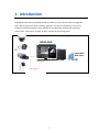
1 Introduction
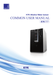
MEGA NVR is Windows-based NVR software provides up to 32 channels video management
and is able to process live view, recording, playback, and event management. It acts as an
excellent surveillance platform which handles all of video/audio streaming for collection,
compression, transmission, storage, analysis, monitoring and management.
MEGA NVR
MEGA NVR
Web client
Up to 32ch
Figure A
1
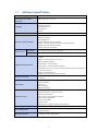
1.1
Software Specification
Max. recording channel
Resolution for monitor
displaying
● 32 channels
● 16:9, 16:10, 4:3, 5:4
Language
● English
● Traditional Chinese
● Simplified Chinese
● Portuguese
● Czech
Video format
● MPEG-4, MJPEG, and H.264 compression format
Real-time video functions
Display layout
● Auto reconnect
● Manual recording
● PTZ & digital PTZ
● Duplicate & remove channel display
● Audio:Listening, 2-way voice chat and audio broadcasting
● Manual snapshot & snapshot viewer
● Popup alarming video window
Live view
● 1, 4, 8, 9, 10, 13, 16, 17, 24, 25, 33, 36, 49,64
Playback
● 1,4, 8, 9, 10, 13, 16
● Speed for playback:1X, 2X, 4X, 8X, 16X, 32X, 1/2X, 1/4X, 1/8X, 1/16X and
Playback video functions
● Live view, Playback, Event searching, PTZ controlling
Backup / Restoring
Action for event
Remote Operation
User Management
Hardware Monitor
● Reverse playing supported
● Event search:Search by event
● Smart search:Search by motion detection
● Thumbnails search:Search by thumbnails decoded from recording file with
certain time interval
● Video saving as AVI format
● Snapshot saving and printing in JPEG format
● Supports two types of media (hard drives and compact discs) for backup and
restoring
● Hardware & storages monitoring
● Motion detection
● DI sensors
● Camera signals
● Manual recording
● Recording
● Display live video in a pop out window
● PTZ preset point action
● Start / stop or control digital-out devices
● Launch other applications
● Send e-mails / SMS
● Take snapshot
● Playing audio or trigger hardware build-in buzzers
Event alarm
1/32X
● Max. channels for video / audio:16 / 1
● Controlling and setting for Local / Remote logging permission, and users
/groups accounts
● Real-time monitoring and notification for the CPU temperature, the CPU
loading and status of system fans
2
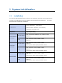
2 System initialization
2.1
Installation
To install the MEGA NVR software, make sure your computer meet the system requirements
as listed in the table below. Then just double-click the setup file and follow the on-screen
instructions to complete the installation.
Server: Windows 7, 32 and 64 bit
OS & Browser
Remote Client: Windows 7, 32 and 64 bit,
IE browser 9 and 10, 32 bit
Giga LAN(1000 Mb/s)
HUB/Switch
Less than 16 ch
CPU : Intel Pentium G860 Dual core, 3.0GHz or above
RAM : 4G
32 ch
CPU : Intel Core i5-3470, 3.2GHz or above
RAM : 4G
Less than 16 ch
CPU : Intel Core i5-3470, 3.2GHz or above
RAM : 4G
Display Card : nVidia chipset, 1G DDR3 or above
32 ch
CPU : Intel Core i7-3770, 3.4GHz or above
RAM : 4G
Display Card : nVidia chipset, 1G DDR3 or above
Less than 16 ch
CPU : Intel Core i5-3470, 3.2GHz or above
RAM : 4G
Display Card : nVidia chipset, 1G DDR3 or above
32 ch
CPU : Intel Core i7-3770, 3.4GHz or above
RAM : 4G
Display Card : nVidia chipset, 1G DDR3 or above
Server without
local client
Server with
local client
Remote Client
3
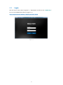
2.2
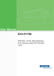
Login
Click the "Start" menu; select "Programs" -> "MEGA NVR” and click on the " MEGA NVR "
icon to run the MEGA NVR software. (Figure 1-1)
Note:Default account:admin / Default password:1234
Figure 1-1
4
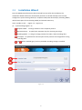
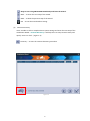
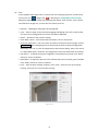
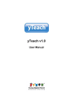
2.3
Installation Wizard
Once the MEGA NVR software has been lunched first time after the installation, the
Installation Wizard will be also automatically started. This wizard will help users to easily
configure the system setting values (ex. Snapshot Folder, Max Record Days, Recording Media,
and the Free Space of the recording media) and Cameras Discovery.
Users are able to click: (Figure 1-2~Figure 1-6)
(1)
System Setting (Figure 1-2)
Snapshot Folder:To assign a folder to store snapshot pictures.
Max Record Days:To specify the maximum days for reserving event logs.
Recording Media:To assign a storage partition for video / audio recording data.
Free Space:To specified the reserved space of this partition that assigned for storing
recording data
and
will be disabled (gray) until any available recording storage is installed.
Figure 1-2
5
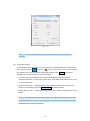
OK:To start using MEGA NVR immediately and leave the wizard.
NEXT:To enter the next step of the wizard.
PREV:To back the previous step of the wizard.
Exit:To exit the wizard without saving.
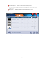
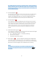
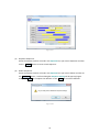
(2)
Cameras Discovery
Users are able to click to complete these system settings and enter the next step of the
Installation Wizard – Cameras Discovery. It will help users to setup cameras easily and
quickly. Users can click:(Figure 1-3)
Discovery:To start the cameras discovery procedure.
Figure 1-3
6
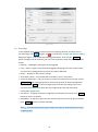
Recording (Figure 1-4):To turn on / off the video recording function.
(Users are needed to prepare the storage of recording for each camera in the system
configuration.)
Add (Figure 1-4):To specify whether the camera to be managed or not.
Figure 1-4
7
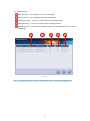
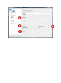
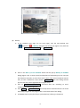
(3)
Cameras Setup
Record Stream:For assigning a stream for recording.
Preview Stream:For assigning a stream for previewing.
Motion Detecting:To turn on / off the motion detecting function.
Audio Recording:To turn on / off the audio recording function.
Recording Mode:To specify the recording mode. (Full-time Recording / Event-driven
Recording)
Figure 1-5
Note:All of these settings are also to be modified later in the System Configuration.
8
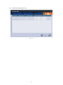
(4)
Confirmation Step (Figure 1-6)
Figure 1-6
9
2.4
Exit the system
If user wants to exit from this program, on the main page of MEGA NVR software, click on
the icon Exit AP
(Figure 1-7a,
), which is located at the upper right corner, a dialog
box which is titled Exit will be pop-up (Figure 1-7b) and you will need an authorized account
to exit system. In the Exit dialog box, you may click the button
system.
Figure 1-7a
Figure 1-7b
10
to give up exiting
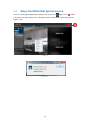
2.5
Log Off and Switch Login User
In the main page of MEGA NVR software, click on the icon Switch User
(Figure 1-7a,
),
which is located at the upper right corner, a dialog box which is titled Switch User will be
pop-up (Figure 1-8) and you will need an authorized account to exit system. In the Switch User
dialog box, you may click the button
to give up log off system.
Figure 1-8
11
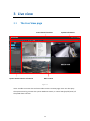
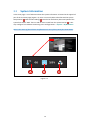
3 Live view
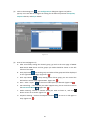
3.1
The Live View page
Cross-channel functions
System status & Source of content
System information
Main content
Figure 2-1
Users are able to monitor the real-time videos on the Live View page; users can also query
the system event log, monitor the system Hardware status, or control PTZ (pan/tilt/zoom) of
the speed dome cameras.
12
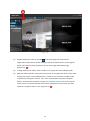
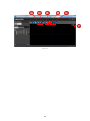
Figure 2-1a
(1)
Double-clicking any video or click the
icon will enlarge this channel into a
single-cannel layout and re-double-clicking it will let the videos restore to the original
layout. This feature is both provided in the Live View page and Playback page.
(Figure 2-1a,
)
(2)
To drag and drop the videos, users are able to re-arrange the channel display order.
(3)
Real-time video snapshot:Move the mouse cursor to the upper left corner of any video
window, the mouse cursor would become a “camera” icon and users are able to take
snapshots by clicking the “camera” icon. Users are also able to open the “Snapshot
Viewer” to browse the snapshots. To open the Snapshot Viewer, users may move the
mouse cursor in any video window and click the right button of the mouse, and then
select the “Snapshot Viewer” item. (Figure 2-1b,
13
)
Figure 2-1b
(4)
Click the right button of the mouse on a channel’s video window (Figure 2-1c), users are
able to do other operations like:
Figure 2-1c
Reconnect:Manually reconnect this channel if there’s trouble of video displaying.
Record Stream:Display for record stream of this channel on live view
Preview Stream:Display for preview stream of this channel on live view
Manual Record:Users can manually start/stop recording despite of the current
recording mode of that channel and search in the playback page. About the duration
14
of an event, it will be defined as the time span from the starting to the stopping of
the manual recording.
Snapshot:Snapshots browsing for all channels and all time
Digital PTZ:Digital zooming
Keep aspect ratio:Change the video displaying ratio to its original ratio rather than
filling the video window
Popup window:Users can select this item to open another pop-up video window for
an important channel. Besides, all of the right-click functions mentioned above for
the real-time videos are also available in this Popup window. (Figure 2-1d)
Figure 2-1d
15
Duplicate:Duplicate a channel display on another one. (Figure 2-1e)
Figure 2-1e
Remove:Remove the channel.
Page:While the number of the real-time videos is more than the max. videos of the
current video layout, the MEGA NVR system is capable to automatically paging these
channels. For example, there’s totally 30 channels user wants to display, but the
layout user selected is 16, so all of the channels displayed will be divided into 2
pages, the page 1 is for channel 1 to channel 16, and the page 2 is for channel 17 to
channel 30.
16
Figure 2-2a
Camera list: Drag any camera in this list into the video display window and the camera’s
live video can be displayed instantly. An icon is located on the left of each camera name
(Figure 2-2a,
), it would help users to aware the statuses of cameras. There are 3 kinds of
status (Figure 2-5b) and users are able to click the icons to get more details about the
cameras’ statuses (Figure 2-2a,
):
Figure 2-2b
17
3.2
About the MEGA NVR System Version
In the Live View page of MEGA NVR software, click on the icon
(Figure 2-3a,
), which
is located at the upper right corner, a dialog box which is titled MEGA NVR will be pop-up
(Figure 2-3b).
Figure 2-3a
Figure 2-3b
18
3.3
System Information
In the main page, a set of indicator about the system information is located at the upper left
part of the Live View page (Figure 2-4). User are not only able to be informed the system
temperature (
) and the CPU loading (
) but also be notified any abnormal speed of the
system fans with a “RED” fan icon and an alarm sound from the system buzzer (
). User
may configure for hardware monitoring in the Configurations -> System -> H/W Monitor.
Note:The status of fan will have notification once one of the system fans break down.
Figure 2-4
19
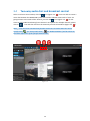
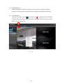
3.4
Two-way audio chat and broadcast control
Select a real-time camera video, click the
icon (Figure 2-5,
), users are able to create a
voice chat between the MEGA NVR system side and the selected camera side. If users are
going to listen to the audio of this channel, just click the
icon (Figure 2-5,
). If user
wants to start audio broadcasting from client PC’s microphone for multiple channels, please
click on
icon and then check on the channels you want to broadcast (Figure 2-5,
Note: Only one voice communicate function can be turn on at the same time and a
specific icon (
for “2-way audio chat”,
for “Audio Broadcast”) will be shown at
the lower-left Conner of the specific channel video.
Figure 2-5
20
).
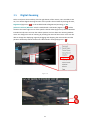
3.5
Digital Zooming
Select a real-time camera video, click the right button of the mouse, users are able to turn
on / turn off the digital zooming function of the specific channel video by clicking the item,
Digital PTZ (Figure 2-6,
). In the enabled mode of Digital PTZ (Zooming), a “PiP
(Picture-in-Picture) Window” which is marked with a red border (Figure 2-7,
) will be
shown at the lower-right corner of the specific channel video (Figure 2-6). This PiP Window
intended to help users to know the relative position and size about the zooming window.
Users can change the scale of zooming by scrolling the wheel of the mouse. Users are also
able to change the displaying region by dragging and dropping the main window and the
position relationship will be shown with a blue-border rectangle (Figure 2-7,
Figure 2-6
Figure 2-7
21
).
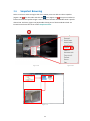
3.6
Snapshot Browsing
Select a real-time video and right click of the mouse, users are able to take a snapshot
(Figure 2-8a,
) for the video and click the
icon (Figure 2-8,
) to open a window to
browse all manual snapshot images. Users are able to browse recorded files with a specific
channel No. and time, (Figure 2-9). By double-clicking one of the thumbnails which are
located at the lower-left corner of the Snapshot Viewer.
Figure 2-8
Figure 2-8a
Figure 2-9
22
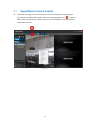
3.7
(1)
Speed Dome Camera Control
In the Live View page, a set of control button for PTZ Controlling is provided (Figure
2-11) which is located at the top part of the Live View page (Figure 2-10,
). Users are
able to control the direction, zooming scale, focus, preset positions, and the speed of
speed dome cameras.
Figure 2-10
23
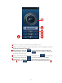
Figure 2-11
Direction:Pan and tilt in 8 directions and patrolling control.
Speed:The speed setting of moving for speed dome cameras, the right to accelerate
and the left compared to slow down.
Zooming Control:Press the
icon can forward the scaling to reduce the
monitoring region (Zoom-in), press the
icon can zoom back to enlarge the
monitored area (Zoom-out).
Focus:Focus function of speed dome cameras, press the
lens focal point closer to the
Preset Position: Press the
2-11,
), press the
icon is about the
icon will be a focal point to pull away.
icon to setup a “Preset Position” (Figure
icon to move to a “Preset Position” (Figure 2-11,
24
).
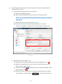
(2)
The following steps will guide you to set the automatic cruise of the speed dome or
cameras with a PT head:
A. Enable the PTZ control functions for a PTZ camera:
(A) Open the Configurations page.
(B) Select a specific Speed Dome Camera item in the IP Camera tree list.
Note: The speed dome camera will be listed under the node, “IP Camera”,
(Figure 2-12).
(C) Switch tab to General, and check the PTZ Enable.
(D) Users will also need to set the following setting for an “IP Camera”:
“Protocol”, “Baud Rate”, “Address ID”, and "Home Position" (Figure 2-12).
Figure 2-12
B. Setup the preset point (Figure 2-13)
(A) Click the PTZ icon which is located at the Live View page (Figure 2-13,
).
(B) Adjust the PTZ angle of the cameras to focus at a specific range which you
want to monitor. (Figure 2-13)
(C) Click on the set button
pop-up. (Figure 2-13,
and a dialog box which is named “PRESET” will be
)
(D) Select the “Preset” No. and input an appropriate description for the specific
“Preset Position”. Click the button
25
Set Preset
to setup a preset position or
click column “Descriptions” for updating descriptions for this preset point.
(Figure 2-13,
(E)
Click the button
)
OK
to complete the setting. (Figure 2-13,
)
Figure 2-13
C. Setup automatic scan (patrolling)
(A) Open the Configurations page.
(B) Select a specific PTZ Camera item in the IP Camera tree list.
(C) Switch tab to General, and click the button
Auto Scan
and a dialog box
Auto-Scan Setting will be pop-up.
Figure 2-14
(D) In the Auto-Scan Setting dialog box, users can change the interval of scanning.
26
(E) Users are also able to drag and drop one or some preset position(s) from the
Available Preset to the Selected Preset.
Figure 2-15
(F) After completing the above steps, click the
OK
button.
(G) You may start / stop the Auto Scan function by click the sequence button
(Figure 2-16,
), which is located at the top part of the Live View page.
Figure 2-16
27
D. Screen Layout
In the main page, click the
icon (Figure 2-17,
) to pop-up a layout box.
Users are able to select a specific layout (1, 4, 8, 9, 16, and so on) in this layout box.
Users can also set specific real-time channel video to "full screen", or change every
video displayed by "group" or "sequence" playback.
Figure 2-17
28
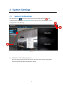
4 System Settings
4.1
System Configurations
Click the setup icon (
) which is located at the Live View page (Figure 3-1,
) and
a dialog window which is titled Configurations will be pop-up. Users are able to set system
configurations as the following:
Figure 3-1
(1)
Shutdown the system when program exit
Once this setting item has been checked, the computer system will be automatically
shut down (power-off) after the program is exited.
29
Note:MEGA NVR System provides one watchdog solution, “Software Watchdog”:
Software Watchdog : Once the MEGA NVR system has not responded or been
terminated by any exception, as long as the operation system is still working, it will
re-start the MEGA NVR system.
(2)
Save Interval (Figure 3-2,
)
This value defines the file length (in minute) of each video data file. The default value is
5 minutes and 8 types of length (1 / 3 / 5 / 10 / 15 / 20 / 25 / 30) are available. For
example, if this configuration has been set to 3 minutes, the MEGA NVR system will
create a new recording data file every 3 minutes (per each available channel).
(3)
Auto Login (Figure 3-2,
)
If this configuration is enabled, the MEGA NVR system will be login with the selected
account after each starting of the operation system. The installation will automatically
create a default account (with an “Administrative” permission) whose user name is
“Admin” and the password is “1234”, users will need to login with an authorized
account and password at each system starting, if this configuration has not been
checked.
(4)
Enable Remote Reboot (Figure 3-2,
)
If this configuration is enabled, any HTTP connection with the input password will trigger
system rebooting for operating system. For example:
(5)
A.
http:// MEGA NVR IP address {:Port Number} / Reboot.cgi
B.
Input the correct password.
C.
The operation system will be rebooted.
Reboot (Figure 3-2,
): Users can configure the operating system of MEGA NVR to
automatically reboot on a weekly day and time. If this configuration is enabled, please
do not set any password for the default login account unless you do not want the MEGA
NVR system be automatically logged in after the MEGA NVR system rebooting.
Note:
The configuration of “Watch Dog” is not available in the MEGA NVR software.
Any change in this Configurations Page won’t be saved until the button
been clicked.
30
OK
has
Figure 3-2
31
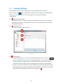
4.2
Storage Settings
To add, modify, delete storage setting groups for streaming data file. Instructions:
Click the setup icon (
) and a dialog window which is titled Configurations will be pop-up.
Click System / Storage in the tree view item, (Figure 3-3) to adjust the following
configurations:
(1)
Max. Event Record Days
The number of days (1~365) for the video recording files saving. Once any recording
file has been kept longer than the duration user set, it will be deleted automatically by
the MEGA NVR system.
(2)
Snapshot folder
The folder for saving snapshot pictures.
Figure 3-3
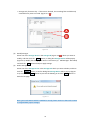
(3)
Add Storages
Storage Media Setting:Set a path for recording data files saving. To click the
Add
button, a dialog box Storage Device will be pop-up (Figure 3-4). To check the items of
the Storage table to assign partitions to be storages and to check the items of the
Information table to assign cameras’ streaming to be stored in this storage group.
Recycle:If this item is checked, once the available spaces of the storages are less than
the settings value, the older recording files will be deleted automatically by the MEGA
NVR system with the deleting unit of one hour. (Figure 3-4,
32
).
Storage Only for Event Clip:If this item is checked, the recording files would be only
saved while any event occurred. (Figure 3-4,
)
Figure 3-4
(4)
Modify Storages
Select one of the storage device in the Storage Lib (Figure 3-3,
modify, and then click the
Edit
) which you want to
button, a dialog box Storage Device will be pop-up
(Figure 3-4). Modify the settings (just like the “Instruction (3): Add Storages” described)
and click the
(5)
OK
button finally to apply settings.
Delete Storages
Select one of the Storage Device in the Storage Tab which you want to delete, and then
click the
Delete
3-4). Just click the
button, a confirm dialog box Storage Device will be pop-up (Figure
Yes
button to process the deleting or click the
No
button to
back the last page.
Figure 3-5
Note:For each camera which is enabled to record, please make sure that each camera
is assigned with proper storages.
33
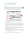
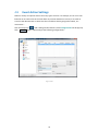
4.3
User Account Management
To add, modify, delete “User” and “Authority Group”.
Instructions:
It is recommended to create some authority groups before creating users, and then assign
users to the specific authority groups. To do these, you will need to click the setup icon (
and a dialog window which is titled Configurations will be pop-up. Click System / Authority
Group in the tree view item, (Figure 3-6) to adjust the following configurations:
Figure 3-6
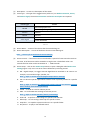
(1)
Add Authority Groups
The Authority Groups can be regarded as the classification of user privileges; users can
achieve permissions management through inheritance from different Groups. Once the
permissions of an Authority Group are changed, the permissions (channel permissions,
system privileges) of all the users that inherited from the Authority Group are also
changed.
If a specific Authority Group is deleted, all the users that inherited from the Authority
Group are also deleted unless there is any the user has been assigned with any
individual permission and it will be remained.
There is a special Authority Group, which is named “Supervisor” and it has been already
created by the MEGA NVR system, which won’t be listed in the “Authority Group” page
but the “Authority Group” of the “User” page.
To create / modify an Authority Group, please refer to the following steps:
34
)
A. Enter the “Name” for the Group in the “Group Name” field.
B. Set Permissions for Channels – In the “Channel authorization” table, users are able
to assign permissions independently for each channel. The permissions include:
(A) Local Preview:Be authorized to open the local real-time video. This permission
is required to browse the local snapshot pictures.
(B) Local Playback:Be authorized to operate the local playback.
(C) Local PTZ:Be authorized to operate the local PTZ controlling. The permission of
“Local Preview” is required to authorize this permission.
(D) Remote Preview:Be authorized to preview the video this channel remotely. The
right of browsing snapshot remotely will also be granted.
(E) Remote Playback:Be authorized to operate the playback remotely.
(F) Remote PTZ:Be authorized to operate the PTZ controlling remotely. But the
permission of “Remote Preview” has to be granted first in order to enable this
permission.
(G) Local Data Export:Be authorized to local export data (Recording data backup,
save snapshot, print snapshot, saving video as AVI files). But the permission of
“Local playback” has to be granted first in order to enable this permission.
(H) Remote Data Export:Be authorized to export data (Recording data backup, save
snapshot, print snapshot, saving video as AVI files) remotely. But the permission
of “Remote playback” has to be granted first in order to enable this permission.
Note: Users are able to check all the permissions by checking the check box
which is nearby the channel number (Figure 3-6,
). Users are also able to
check all the channels to grant a specific permission by clicking the check box
which is near by the permission (Figure 3-6,
).
C. Set Permissions for System – In the Authorization table (Figure 3-6,
); users are
able to grant permissions for the MEGA NVR system operating. The permissions
include:
(A) System Shutdown:Be authorized to exit the MEGA NVR system.
(B) View Log:Be authorized to browse the event log of the MEGA NVR system.
(C) Export Log:Be authorized to export (saving as, printing) the event log of the
MEGA NVR system.
(D) Local Setup:Be authorized to change the configurations of the MEGA NVR
system.
(E) Local DO Control:Be authorized to control the digital output devices of the
MEGA NVR system.
(F) Remote Setup:Be authorized to change the configurations of the MEGA NVR
system remotely.
35
(G) Remote DO Control:Be authorized to control the digital output devices of the
MEGA NVR system remotely.
D. Duplicate Authority Groups
If you want to create an Authority Group which is similar to any existing Authority
Group, you can duplicate a new Authority Group from the existing one first, and
then modify the settings for the new one. The steps as the following:
(A) Tap the existing authority group you want to duplicate.
(B) Enter a new name for the new Authority Group in the Group Name field.
(C) Click the button
Copy , and a new Authority Group would be successfully
created (duplicated).
(D) Tap the new Authority Group which is just been created, adjust the permission
settings of channels and system.
(E) Click the button
Update
to complete and apply the operation.
E. Update Authority Groups
To modify an existing Group, the steps as the following:
(A) Select the item which is to be modified first
(B) Adjust the permission settings of channels and system.
(C) Click the
(2)
Update
button to apply the setting.
Add a user (Figure 3-6) Admin
Each user must be inherited at least from one Group (or more than one Group). All of
the inherited permissions are granted (union operation) and cannot be removed. A user
is not only granted with inherited permissions but can also be granted with
non-inherited permissions. Non-inherited permissions can be granted or removed to any
users. The inherited permissions do not affect the non-inherited permission unless the
user is operating actions which involved non-inherited permissions.
A. Enter the Basic Information of User (in the Base Data tab) (Figure 3-7,
)
(A) User Name:The name of account. Alpha letters, numbers, special symbols
(1~50 characters) are accepted.
(B) Password:The password of account, 1~50 characters are accepted.
(C) E-Mail:The e-mail address of the user.
(D) Phone number / Mobile Phone Number:Only numbers (0~30 characters) are
accepted.
(E) Once you complete the above items, please select at least one Authority Group
in the Authority data tab, and then click the
account. (Figure 3-8,
)
36
Add
button to create a new
(F) You can select an account which is listed in the table Authority Information
(Figure 3-9,
) and then modify settings for updating.
(G) You can also select an account which is listed in the Authority Information table
and click the button
Delete
to delete it.
Figure 3-7
Figure 3-8
37
B. Set Information of Permissions
(A) Select inherited permissions of Authority Group
Check one or more (at least one) Authority Group from the Authority Group.
(Figure 3-9,
).
(B) Grant additional non-inherited permissions
Check the non-inherited permissions from the Channel Authorization (Figure
3-9,
) and Authorization. (Figure 3-9,
).
Figure 3-9
(C) Duplicate accounts
If you want to add a new account by copying permissions and other settings
from an exist account, you may select the account which you want to duplicate
and modify the user name and finally click the button
Copy
to complete the
account-duplicating.
(D) Delete accounts
Select the user which you want to delete and click the button
then click the button
Yes
Delete , and
in the confirmation dialog box (Figure 3-10) to
confirm the deleting.
38
Figure 3-10
(E) Update accounts
Select a user which is to be updated, modify the information and click the
button
Update
to apply the change.
39
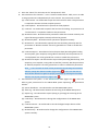
4.4
Hardware Monitoring
The MEGA NVR system provides monitoring of the CPU temperatures and fan status.
Instructions:
Click the setup icon (
) and a dialog window which is titled Configurations will be pop-up.
Click the tree view item, System / H/W Monitor (Figure 3-11), to adjust the following
configurations:
(1)
Max CPU Temperature:The high-temperature warning for CPU. The default value is 80.
(Figure 3-11,
)
(2)
Temperature Unit:Celsius or Fahrenheit. (Figure 3-11,
(3)
Fan Speed:If this item is checked, the system will automatically get real-time speed of
the fan; (Figure 3-11,
(4)
)
)
System Fan Monitor:If this item is checked, the MEGA NVR system will alert users while
any speed of fan is less than the setting value. (Figure 3-11,
Figure 3-11
40
)
4.5
IP Camera Management
Click the setup icon (
) and a dialog window which is titled Configurations will be pop-up.
Click the tree view item, IP Camera (Figure 3-12), to adjust the following configurations:
(1)
Manually add an IP camera (Figure 3-12):
C. Model:Specify a proper model.
D. Channel / Camera ID:The MEGA NVR system will automatically assign these two
items.
E. IP Address:The IP address for the connected IP camera.
F. Camera Name:A name or description for the IP camera.
G. Account / Password:The account and password for the IP camera.
H. After complete the above items (
specific camera by click the button
I.
to
), users are able to get the profile of the
Get IP Camera Profile .
Record Stream / Preview Stream:Select proper properties for the record stream
and preview stream. The values of properties would be just noted as “Stream 1” /
“Stream 2” unless users click the
Get IP Camera Profile .
J. Specify a proper storage for the IP camera.
K. Finally, click the
Add IP Cameras
to apply the above settings.
Figure 3-12
41
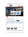
(2)
Automatically Find IP Cameras:
A. Click on the
Find IP Cameras (Figure 3-21,
) button, a wizard named Add Camera
will be started. The wizard is able to help users to easily discover cameras which are
connected to the network. To start the discovery, just click the 00000icon (Figure
3-13,
). After few seconds, any available camera will be listed in the table. By
checking the corresponding check-box, users can not only add them to be a
managed IP camera but also specify the default setting of Recording (Figure 3-14).
B. In each step of this wizard, users are able to click the
click the
icon to back to the previous page, click the
close the wizard, or click the
icon to switch next page,
icon to cancel and
icon to finish the wizard and apply changes.
Figure 3-13
Figure 3-14
42
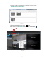
2 of the wizard (Figure 3-15), users are able to setup the default
C. In the next step ○
options of cameras. All these settings will also be modified later.
(A) Recording/Preview stream:Choose a stream for previewing or recording from
available streams of a channel.
(B) Motion Detection:To enable full-area motion detection or no motion detection.
(C) Audio Recording:To enable audio recording or not.
(D) Recording Mode:Choose to enable full-time recording or event recording
(with motion detection, DI events etc.).
Figure 3-15
43
(E) Storage: Choose a specific storage media for recording. (This column would not
be displayed on the first time running of Installation Wizard.)
Figure 3-16
(F) In the next page of the wizard (Figure 3-16), all cameras to be added which
2 and their option settings would be listed in the
user checked in the page ○
table for confirming. Users are able to modify those settings or finish the
procedure.
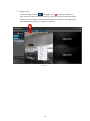
(G) Users are able to click the
Discovery Wizard (Figure 3-1,
(3)
icon which in the Live View page to open this
).
Modify the IP Camera settings:
A. Connection (Figure 3-17).
(A) Click
Setting
at the main page, choose a channel and choose on the
Connection
button a dialog box Camera Connection Setting will be pop-up (Figure
3-18). Users can modify the IP Address, HTTP Port, Account, and Password, and
finally click the
OK
button to complete the modification.
44
Figure 3-17
Figure 3-18
(B)
Click on the
Camera Setting
button, the Web user interface of the camera
will be opened (Figure 3-19), after editing, click
browser.
45
Save
and close the internet
Figure 3-19
(C)
Click the
Delete Camera
button, a confirm dialog box will be pop-up to
confirm the deleting (Figure 3-20). Check for the deletion-related items and click
Yes
to delete the selected camera according to user’s requirement.
Figure 3-20
46
B. General (Figure 3-21)
Figure 3-21
Camera Enable:When checked, the channel will be activated.
Camera Name:A name or description for the camera.
Font Display Size, Font Display Color:The font size and font color settings for
the OSD on the real-time video.
Record Stream:To specify a proper stream for recording
Preview Stream:To specify a proper stream for previewing.
Video Record Enable:Enable or not to record the video.
Audio Record Enable:Enable or not to record the audio.
Record when event occurred only:If this item is checked, the recording won’t
be started unless any event occurred.
PTZ Enable:Enable or not the controlling of PTZ for a speed dome camera or a
camera with a PT Head.
Record Schedule:Users can specify the recording schedule by weekdays or
dates. (Figure 3-22)
47
Figure 3-22
Pre-record time / Post Record time (Figure 3-21):The length of time for event
recording. The system default value is 3 seconds for pre-recording and 10
seconds for post recording. This function usually works with the motion
detection or other events related to cameras. Once any event occurred, 3
seconds of video will be recorded before the occurring time of event (can be set
between 0~10 seconds), and 10 seconds of video will be recorded after the
occurring time(can be set between 0 and 3600 seconds), in this example, the
entire length of recording is totally 13 seconds.
48
C. Motion:(Figure 3-23).
Motion Enable:To check it to enable the motion detection function.
Event Interval Time:If several events occurred within Event Interval Time, all of
the events will be treated as a single event. This default value is 10 seconds and
can be set between 0 ~ 3600 seconds.
Sensitive:This setting defines the sensitivity of the motion detection. This
default value is 80 and the value can be set between 1~100. The higher value
means the higher sensitivity.
Add Action Zone:Click this button to create a zone for motion detection.
Delete Action Zone:Click this button to specify a zone which is disabled for
motion detection.
Select Whole Zone:Click this button to set the whole area on the video become
detection zone.
Delete All Zone:Click this button to disable all motion detection zones in the
picture.
Motion detection schedule:To set when to enable/disable the motion detection
according to weekday/hours or calendar date. (Refer to Figure 3-24)
Note:One channel can only have one detection zone; therefore no matter how
many zones are drawn in a channel, they will all be regarded as one
irregular-shaped zone.
Figure 3-23
49
Figure 3-24
50
4.6 Group Settings
User can create, update, duplicate, and delete channel groups in this section. Instructions:
Click the setup icon (
Choose
(1)
Group
) and a dialog window which is titled Configurations will be pop-up.
in the function tree (Figure 3-25) to adjust the following configurations:
Add a group
A. Group Name
:
B. Input a name for the Camera Group.
C. Select Camera
:
D. Users can select several cameras join the group by simply dragging a camera which
is listed in the Camera list and dropping it in the Select Camera list. Repeat this
drag-and-drop process until you have selected all cameras you want to be in this
group, and finally click the
Add
button to complete the operation.
Figure 3-25
51
(2)
Duplicate Groups
Select the group (which is listed in the Group list) you want to duplicate and click on the
Copy
button to create a new group, and then you can assign a new name for the new
group.
(3)
To delete the group
Select the group (which is listed in the Group list) you want to delete and finally click on
the
(4)
Delete
button to delete it.
Update Group
Select the group (which is listed in the Group list) you want to update, modify the
contents, and then click the
Update
button to update the group information.
52
4.7
Sequence Settings
To provides the “Recursive Playing” function across camera groups. The “Sequence” can be
created, updated, duplicated, and deleted by users.
Instructions:
Click the setup icon (
) and a dialog window which is titled Configurations will be pop-up.
Click the tree view item, Sequence (Figure 3-26), to adjust the following configurations:
(1)
Create Sequences
A. Sequence Name:A name or a description of this Sequence mode.
B. Interval Time:This time is defined the time how long to wait to switch to the next
Group (Camera Group) to display.
C. Schedule Setup:Click the
Schedule Setup
button, users can assign different
Sequences by a weekly or daily schedule (Figure 3-27). Therefore, desired sequence
mode will be automatically started and stopped in the period defined by the user.
D. Enter Sequence Name and Interval Time for the new Sequence and drag Groups
from the right list and drop them into the left list, and finally click the
button to complete the creation of Sequence.
Figure 3-26
53
Add
Figure 3-27
(2)
Duplicate Sequences
Select the Sequence (which is listed in the Sequence list) you want to duplicate and click
on the
(3)
Copy
button to create a new Sequence.
Delete Sequences
Select the Sequence (which is listed in the Sequence list) you want to delete and click on
the
Delete
3-28), click
button, a confirm dialog box Sequence Setting will be pop-up (Figure
Yes
to complete the deletion or click
Figure 3-28
54
No
to cancel this deletion.
(4)
Update Sequences
Select the Sequences (listed in the Sequences list) you want to update, modify the
contents, and finally click the "Update" button to update the Sequences information.
(5)
Start Sequencing
In the Live View page, click the
icon (Figure 3-29,
), and then the list of available
sequence modes will show up, just select one to start the sequence. Click on the mode
again to stop it. (Figure 3-29)
Figure 3-29
55
4.8
Event Action Settings
Define a variety of response actions for every types of event. For example, to turn on a siren
linked on an IP camera for 10 seconds while any motion detection occurred, or to send an
e-mail to the administrator to alert him that a hard drive disk is going to be broken, etc.
Instructions:
Click the setup icon (
Click
Action
) and a dialog window which is titled Configurations will be pop-up.
(Figure 3-30) to adjust the following configurations:
Figure 3-30
56
(1)
Description:A name or a description of the Action.
(2)
Event Type:The type of the trigged event (Table 3-1). For Motion Detection, Sensor,
and Camera Signal, the items Device Name and Device Description are required.
Event Type
Record
Status
Recording space full
Recording storage regain space
Motion
Motion
Sensor
Sensor
Video Signal
Video loss
Video Detected
Table 3-1
(3)
Device Name:A name of the device that the event belongs to.
(4)
Device Description:A name of the device that the event belongs to.
Note: Please refer to Section 4.11 Sensor Settings.
(5)
Action Interval:If the same event occurred within a period of event interval more than
one time, all of the events will be treated as a single event. This default value is 10
seconds and the value can be set between 0 ~ 3600 seconds.
(6)
Action Setup:Click on the Action Setup button to open a dialog box titled Action Item
Setting (Figure 3-31). Users can set an action definition by selecting actions.
A. DO:Digital Output, to trigger external digital devices attached on IP camera. For
example, siren and alarm light, speaker, etc.
Note: Refer to Section 4.10 DO (Digital Output Device Settings).
B. PTZ:To drive the specific speed dome camera to aim a specific position for a specific
time.
Note: Refer to Sections 3.7 Speed Dome Camera Control and Section 4.8 Event
Action Settings (PTZ related information)
C. E-Mail:To send an email to relevant person.
D. SMS:To send a SMS text message to relevant person.
Note: Refer to Section 4.9 SMS / Email / FTP Settings.
E. HTTP Call:To perform a CGI calling to a specific HTTP web site.
F. Video Clip:To start saving a video clip of a specific camera.
G. Snap Shot:To snapshot a picture and save it to a specific folder.
H. Play Sound:To play a user-defined sound.
57
I.
Display:To pop-up a window with user-defined live video of a channel with optional
auto-countdown to close window; or to display the real-time videos of a specific
camera or a camera group for a user-defined time replacing the original previewing
video channel temporarily.
J. Execute App:To execute a specific application on this local server.
Figure 3-31
(7)
After setting, and then finally click the
(8)
Duplicate Action:
Add
button to complete the creation.
Select the Action which you want to duplicate, modify the Action Settings, click the
button
(9)
Copy , you can create another new Action.
Delete Action:
Select the Action which you want to delete, click the button
Yes
Delete , and then click the
button in the confirmation dialog box to confirm the deleting
(10) Update Action:
Select the Action which you want to update, then modify the Action Settings and click
the button
Update
to apply the change
58
4.9
SMS / Email Settings / FTP Settings
Set configurations for SMS, E-Mail, and FTP. If any Action Definitions involved SMS, SMTP, or
FTP, these configurations must be set correctly. Instructions:
C lick the setup icon (
) and a dialog window which is titled Configurations will be pop-up.
Click the tree view item, SMS\SMTP\FTP (Figure 3-33), to adjust the following
configurations:
(1)
SMS settings
A. SMS:SMS function is enabled when checked,
B. Serial Port Number:Select a port can be used to send SMS.
C. Baud Rate:The system defaults to 115200, system provides 2400 / 4800 / 9600 /
19200 / 38400 / 57600 / 115200 / 230400 a total of eight kinds of users based on
the need for choice.
(2)
SMTP (E-Mail) settings
A. Host Name:Enter the FQDN (Fully Qualified Domain Name) of the host.
B. Port:Enter the port number of the host.
C. Authentication Mode:“True” (YES) or “FALSE” (NO) to authenticate the account
while sending.
D. Account / Password:Username / Password.
E. Language Code:The encoding code. The system default is Unicode (UTF-8) and the
following are available:
59
Figure 3-32
F. Sender E-Mail:Users can assign an e-mail address of the sender here.
G. Sender name:Users can assign a name of the sender here.
Figure 3-33
60
(3)
FTP settings
A. Host Name:Enter the FQDN (Fully Qualified Domain Name) of the host.
B. Port:Enter the port number of the host.
C. Account / Password:Username / Password.
D. Remote Directory:The name of a directory which is the destination directory for
uploading. This directory will be automatically created in the home directory.
E. Passive:Check this check box if the FTP site is in Passive Mode.
61
4.10 DO (Digital Output) Settings
Set the configurations about the digital output devices that are connected to IP Cameras. For
example, speakers, alarms, etc. Instructions:
C lick the setup icon (
) and a dialog window which is titled Configurations will be pop-up.
Click the tree view item. DO Device (Figure 3-34), to adjust the following configurations:
(1)
Add a device
Device Name:Select a name of the IP camera.
Device Port:The port number of the master device.
Device Description:Descriptions of the DO device.
Click the
Add
button to add a new device.
Figure 3-34
(2)
Delete the device
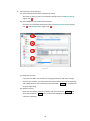
Select a DO Device which is to be deleted from the DO Device list, click the
button, a confirmation dialog box (Figure 3-35) will be pop-up, just click the
button or complete the deleting.
62
Delete
Yes
Figure 3-35
(3)
Update the device
Select a desired DO Device which user need to updated from the DO Device list, modify
the contents, and then click on the
Update
63
button to complete the updating.
4.11 Sensor Settings
This instruction describes how to create, delete, or update the configurations about sensors
(ex., Door Sensor, Smoke Detector, etc.):
Click the setup icon (
) and a dialog window which is titled Configurations will be pop-up.
Click Sensor on the tree view items (Figure 3-36) to adjust the following configurations:
(1)
Add a sensor device
Device Name:Select a name of the IP camera.
Device Port:The port number of the master device.
Camera Name : To define which channel is actually related to the sensor, so when
the sensor is triggered, the related camera will have related actions like video
recording or taking a snapshot.
Device Description:A description for the sensor device.
Add:After finishing of the above settings, users can click the
Add
button to
add a new sensor device.
Enable:If this box is un-checked, MEGA NVR will not process the notification from
this sensor.
Mode:Users are able to select one mode to define a time segment (weekly or
specific days), a description, an interval, and a delay time for the sensor
Figure 3-36
64
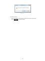
(2)
Remove the sensor device
Select a sensor device which is to be deleted from the Sensor Device list first, and then
click the
Delete
click the
Yes
button, a confirmation dialog box will be pop-up (Figure 3-37). Just
button to complete the deleting or click the
No
button to cancel.
Figure 3-37
(3)
Update a sensor device
Select a sensor device which is to be updated first, modify the settings, and finally click
the
Update
button to complete the updating.
65
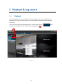
5 Playback & Log search
5.1
Playback
Users can playback and query out desired time spot by date/ time, events, snapshots, and
bookmarks, or process an “Smart Search” by motion detection analysis toward recording file.
Instructions:
In the Live View page of the MEGA NVR system, click the Playback icon (
the page will be switched for the Playback View page (Figure 4-1,
Figure 4-1
66
).
) and
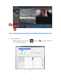
Figure 4-2
Note: An authorized permission is required to do the following about playback operation.
(1)
Date / Time Search
A. Click on the Search By Time icon (
) (Figure 4-2,
Time dialog box (Figure 4-3)
Figure 4-3
67
), pop-up the Search By
B. In the calendar box (upper part of the Search by Time), the date which is marked
with green background indicates there are some recordings have been saved.
C. In the camera-time-schedule list (lower part of the Search by Time), the time
segment which is marked with blue background indicates the corresponding camera
has recording files at the time segment. There is a vertical blue line which indicates
the base time of the playback.
D. Users are able to move the blue base time line to any time, and then click the
Search
button, the Search by Time dialog box will be closed and the base time of
the playback is changed correspondingly.
E. Press the
(2)
icon (Figure 4-2,
) will start playback of the video.
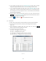
Event Search
A. Firstly, select a camera which is to be searched on the main console of playback.
B. Click on the Event Search button, Search by Event dialog box will be pop-up
(Figure 4-4).
C. After specifying the condition (date, time, event type, etc.), click the
button, it will list the event log about the camera.
D. For the event log, there are four types:
(A) Motion:Be trigged by motions detected.
(B) Sensor:Be trigged by sensors active.
(C) Video Signal:Be trigged by videos missed or recovered.
(D) Manual Record:Be trigged by users’ Manual Recording.
Figure 4-4
68
Search
Select a event log and click the
Select
button, the Search by Event will be closed
and the playback time will be jumped to the time of the event, and automatically
start to play.
If “save video clip” for this channel was set when setting event action, user will be
able to see a “
” mark next to the event log in the Search by Event dialog box.
Then user can directly select on the log with video clip and click the
Play
button,
a video window will pop out and the event video clip will aumatically start to play.
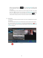
(3)
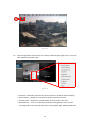
Smart Search
It can help users to analysis and check a specific area in the recording files with a specific
time segment.
To start an Smart Search process, users should select a camera which is to be analyzed
first, and then click the Search By Smart in the Playback Viewpage (Figure 4-5,
), and
assign the conditions (date, time, sensitivity, and interval) in the Search By Smart {name
of camera} dialog box.
Figure 4-5
69
Figure 4-6
A. Select Motion Area:Click this button to define the areas for motion detection
(Figure 4-6).
(A) To add a new detecting area, check the Add Motion Zone check-box first, and
then start to assign which part to be added.
(B) To delete a detecting area, check the Delete Motion Zone check-box first,
and then start to assign which part to be deleted.
(C) To add all the detection area, click on the
Select Whole Motion Zone
button.
(D) To delete all the detection area, click on
70
Delete All Motion Zone
button.
Figure 4-7
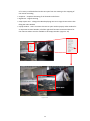
B. After assigning the detecting zones, click on
Search
button (Figure 4-6), you
can analyze the selected zone on the recording video and search results will be
displayed on the dialog. Click on one of these results, and click on "select" button
to return to main console of playback and automatically start to play from the
event time spot(Figure 4-8)
C. If you want to stop the event searching process, click “Stop” button.
71
Figure 4-8
Figure 4-9
72
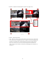
(4)
Thumbnail search
A. In the playback view page, select a channel you want to execute thumbnail search.
And then click the Thumbnail Search icon (
) (Figure 4-9,
). A “Thumbnail
search {Camera name}” dialog box will be pop-up. (Figure 4-10)
B. Select the date and start time for this search, and enter a valid interval (the time
interval between each thumbnail) and click on
Search
button.
C. Thumbnails will be displayed on the left upper side of the dialog with their time
under the image. If thumbnail can’t be retrieved, the icon (
) will be shown.
D. Video preview: Click on any thumbnail and click
for video previewing from the time spot of that thumbnail with forward/backward
playing, pause, and go to next or previous time spot.
E. Click
Select
and you will go back to the Playback View page and the time bar will
be jumpped to the time of the selected thumbnail and automatically start to play.
Figure 4-10
73
(5)
Print
In the Playback View page, select a camera from one of playing channels, and then click
on the Print icon (
)(Figure 4-9,
), it will bring on a Image Edit {camera name}
dialog box (Figure 4-11), modify the following information, then click the "Print" button,
and select Print image size, you can have the picture print out.
Rotation:180 degree rotating for this photograph.
Crop:Select a region on the photo by dragging & dropping, then click on this button,
this area can be enlarged and rest of the area will be deducted.
Revert:Restore for the previous change.
Show Date / Name:Put Camera Name and Date / time on the picture.
Save with watermark:User can choose to overlay a watermark on the image. Click on
Watermark
and a dialog (Figure 4-12) will be pop-up with all related configuration.
Afterward, click “ok” to save all configurations and close the dialog. Then if user check
on “Show Watermark” check box, the image will be save with watermark successfully.
HSL effects:To adjust the picture’s Brightness and Saturation instantly. Click "Reset"
button to restore to default.
RGB effects:To adjust the picture's color scheme with the level of red, green and blue.
Click "Reset" button to restore to default.
Print:After all above settings are done, press “Print”, select the size of the actual
printing, and click “ok” to activate the printing.
Figure 4-11
74
Figure 4-12
Note: To use the Photo Print functions, the privilege of local data export is
required.
(6)
Save Video (as AVI)
In the Playback View page, select a camera from one of playing channels, and then click
the Save Video icon (
) (Figure 4-9,
), pop-up Save Video {camera name} dialog
box (Figure 4-13). After finishing the following settings, press
Save
and set the
storage path, the AVI file will be saved successfully.
To set the start/end date/time of the video saving period, user can input the
date/time manually, or select from event’s time, from manual snapshot search’s time,
or from a bookmark.
Displays watermark: Save AVI movies with watermark overlay. Check the Show
Watermark check box, and click
Watermark
for detail settings.
Display Name / Date: Check for displaying the camera’s Name and Date/time on the
image.
Note: To enable the function of Save Video, the right of “local data export” must
be granted first. The progress of saving and the date/time of on-going data will be
displayed in the “Progress” column.
75
Figure 4-13
(7)
Save image
In the playback page, select a camera from one of playing channels, and then click on
the Save Image icon (
)(Figure 4-9,
), it will bring on a Image Edit {camera name}
dialog box (Figure 4-14), modify the following information, then click the
Save
button on upper side of this dialog, you can have the picture saved and the dialog will be
closed.
Rotation:180 degree rotating for this photograph.
Crop:Select a region on the photo by dragging & dropping, then click on this button,
this area can be enlarged and rest of the area will be deducted.
Revert:Restore for the previous change.
Show Date / Name:Put Camera Name and Date / time on the picture.
Save with watermark:User can choose to overlay a watermark on the image. Click on
Watermark
and a dialog (Figure 4-12) will be pop-up with all related configuration.
Afterward, click
OK
to save all configurations and close the dialog. Then if user
check on Show Watermark check box, the image will be save with watermark
successfully. (Figure 4-12)
HSL effects:To adjust the picture’s Brightness and Saturation instantly. Click
Reset
button to restore to default.
RGB effects:To adjust the picture's color scheme with the level of red, green and blue.
Click
Reset
button to restore to default.
Note: To enable the function of Save Image, the right of “local data export” must
be granted first.
76
Figure 4-14
(8)
Backup
A. In the Playback View page (or Live View page), click the Save Backup icon
(
)(Figure 4-9,
options –
), a Backup dialog box will be pop-up (Figure 4-15) with two
Back up to the HardDisk
or
Burn to CD :
Figure 4-15
B. Click on the Back up to the HardDisk button will be pop-up Backup to HardDisk
dialog (Figure 4-16). To set the start/end date/time of the backing up, user can input
the date/time manually, or select from event’s time, from manual snapshot search’s
time, or from a bookmark. If user chooses
Burn To CD , the same dialog will also
pop out with only some slight difference (Figure 4-17).
C. Click on
Detect Burn Volume , estimated data size according to user’s
configuration will be brought out.
D. Click
Burn
or
Start to backup , the backup will be started and users can check
the backup progress on the progress bar on the lowest side of this dialog.
E. Use MEGA Player to play the file you just backed up. (refering to Chapter 8)
77
Figure 4-16
Figure 4-17
78
Figure 4-18
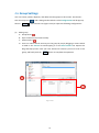
(9)
Bookmark
Users are able to make bookmarks during video playback when finding any important
moment in the record. Users are also able to jump the playback to a specific moment
which has marked as a bookmark.
A. Add a bookmark (Figure 4-18)
Click on the icon (
) (Figure 4-18,
Enter the name of the bookmark and click
), a dialog Add Bookmark will be pop-up.
Save
to save this bookmark.
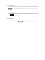
B. Playback by Bookmark (Figure 4-19)
(A) Click the icon (
) (Figure 4-18,
(B) Choose one and press
). The menu of Bookmark will be pop-up.
Select , the time axis of playback will be jumped to the
time of the bookmark you selected and automatically start to play video.
(C) To delete a bookmark, choose a bookmark you want to delete and press
Delete .
79
Figure 4-19
Figure 4-20
80
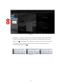
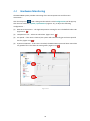
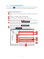
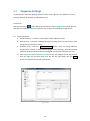
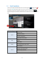
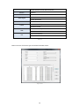
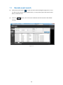
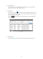
5.2
Event Log Query
In the Live View page of the MEGA NVR, click on the View Log icon (
) (Figure 4-21,
) to
bring up the View Log dialog box (Figure 4-22). Users are able to query the log with one or
some filters (ex. Date, Start / End time, Event type / status, etc.), and then click Search , the
logs will be brought out immediately. Afterward, users are able to save as CSV format or print
it out.
Figure 4-21
Event Type
Status
System leave
Application startup
System
Exit application
Change configuration
Create Web server Failed
Login
Login
Logout
Login Failed
Recording space full
Record
Recording storage regain space
Record Failed
Remote View Connected
Remote View Disconnected
Connect
Remote Play Connected
Remote Play Disconnected
RTSP Remote Client Connected
81
RTSP Remote Client Disconnected
Motion
Motion
Sensor
Sensor
Video Signal
Manual Record
E-Mail
SMS
FTP
Video loss
Video Detected
Manual Record
Sent successfully
Failed to send
Sent successfully
Failed to send
Sent successfully
Failed to send
Table 4-1
Below is the list of all event type and related selectable status.
Figure 4-22
82
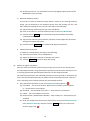
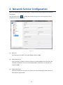
6 Network Service Configuration
Users can remotely browse for video/audio, e-map and event logs through Internet Explorer.
Instructions:
Click the Setup button
, a dialog box named Configurations will be pop-up. Click on
the Network Service (Figure 5-1):
Figure 5-1
(1)
Base port
The starting port number. The system default value is 12480.
(2)
Enable Web Server
If this check box is checked, remote connections via MEGA NVR remote web client are
allowable. Otherwise, users can’t access MEGA NVR via web client. The default port
number is 8086.
(3)
Enable RTSP server
Check for this function and users can retrieve live view streaming via RTSP protocol on
other players support RTSP.
83
(4)
Enable time synchronization
If the checkbox is checked and the IP is inputted, MEGA NVR system will automatically
synchronize its time with a NTP (Network time protocol) server as the IP user key-in.
(5)
Enable Dynamic DDNS (Dynamic Domain Name Server)
Set the domain name of MEGA NVR for being able to be visited through a domain
name address via Internet Explorer. Please check Enable DDNS first, and key-in DDNS
provider, domain name, account and password.
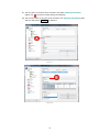
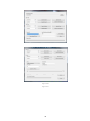
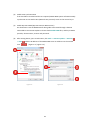
(6)
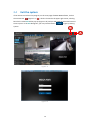
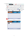
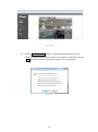
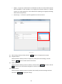
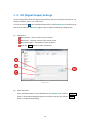
After setting above, open an IE browser, click Tools -> Internet options -> Security
-> Sites
sites
, add the IP address of the MEGA NVR server IP address into the trusted
(Figure 5-2 / Figure 5-3).
Figure 5-2
Figure 5-3
84
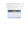
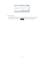
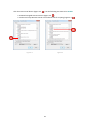
Click the Custom Level button (Figure 5-2,
), set the following two items to be Enable.
Download unsigned ActiveX controls (Figure 5-4,
)
Initialize and script ActiveX control not marked as safe for scripting (Figure 5-5,
Figure 5-4
Figure 5-5
85
)
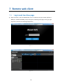
7 Remote web client
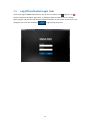
7.1
Log-in and Live View page
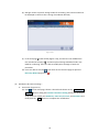
(1) Open IE browser, enter the MEGA NVR server’s IP address with port number (default is
8086) (ex. 10.62.8.254:8086), and you will get the following web pages, the Log in page
(Figure 6-1) and the Live View page (Figure 6-2).
Figure 6-1
Figure 6-2
86
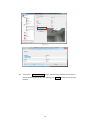
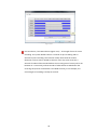
(2)
Click on the Setting icon
, the Configurations dialog box (Figure 6-3) will be
pop-up. Users are able to configure the setting for the JPEG compression of Snapshot,
Sequence details, and Player details.
Figure 6-3
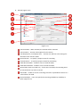
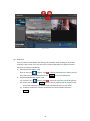
(3)
Start to live view(Figure 6-4)
A. After successfully setting the channel group, go back to the main page of MEGA
NVR remote WEB clients and the groups you made should be shown on the left
column of this page.
B. Click play button
next to the group and video of that group will all be displayed
on the right side of this page. (Figure 6-4,
C. Click stop button
)
to stop viewing video of that group, you can control the
ball machine and for page segmentation. (Figure 6-4,
D. Press video layout
)
to choose a video layout you desired. (Figure 6-4,
E. PTZ controlling:If the channel you select supports PTZ, you can control its PTZ via
the PTZ Control Board.
(Figure 6-4,
)
F. Audio Listening:Choose a channel which you want to listen to, and click on
button to turn on its audio. (Figure 6-4,
)
G. Sequence viewing:Click on the Sequence button
stop. (Figure 6-4,
)
87
to start it or click again to
Figure 6-4
88
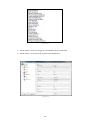
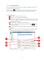
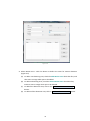
7.2
(1)
Remote event search
Click Event Search button
to open the Event Search dialog box (Figure 6-5). Users
are able to query events with a specific filter, ex. Time, Event Type, Event Status, Event
Name, and Device Port.
(2)
Click the
Reset
button, all of the search conditions will be restored to the default
settings.
Figure 6-5
89
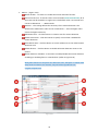
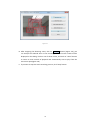
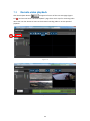
7.3
Remote video playback
Click the Playback button
6-6
on the upper left corner of the Live View page (Figure
) and user will enter “Remote Playback” page. There are 2 ways for retrieving video
data. User can also choose to listen to the channel recording audio or set the speed of
playback.
Figure 6-6
Figure 6-7
90
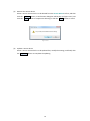
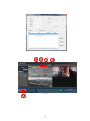
(3)
Channel selection
Choose playback channels by dragging channel from the tree on the left side of this
page, and drop it on the video window user desired.
(4)
Event Search
Click Event Search button
to open the Event Search dialog box (Figure 6-8). Users
are able to query events with a specific filter, ex. Date of Occurrence, Event Type, Event
Status, Event Name, and Device Port.
Click the
Reset
button, all of the search conditions will be restored to the default
settings.
Figure 6-8
(5)
Playback speed
Click on Playback Speed and you will be able to set the play speed of all the video.
91
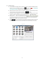
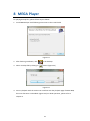
8 MEGA Player
For playing backup files, please follow steps as below:
1. Install MEGA Player with following instructions in the install shield.
Figure 8-1
2. After finishing installation, click
on the desktop.
3. Select a backup file by clicking on
button (Figure 8-2)
Figure 8-2
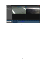
4. Start to playback with the similar user interface with the playback page of MEGA NVR,
but some functions are disabled. (Figure 8-3) For detail operation, please refer to
Chapter 5.
92
Figure 8-3
93
9 Abbreviation and definition
PTZ:Pan (Up and down), Tilt (left and right), Zoom & Focus control for speed dome,
PT camera, camera with PT head attached, and camera with motorized zooming lens
MPEG-4:Moving Pictures Experts Group, as the video/audio compression format
H.264:Video/audio Codec compression format
FPS:Frame per Second, indicates how many frames in one seconds for a video.
Higher FPS value, more vivid the video
1080P:A kind of resolution, equal to Full HD, 1920 x 1080 two million pixels
720P:A kind of resolution, equal to HD, 1280 x 720 one million pixels
D1:A kind of resolution, 720 x 480 pixels
VGA:A kind of resolution, 640 x 480 pixels
CIF:A kind of resolution, 352 x 288 pixel
DDNS:Dynamic Domain Name Server/Service
AVI:Audio Video Interleaved
BMP:An image format without compression
JPEG:An image format with compression
IP:Internet Protocol, Internet Protocol address
94