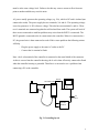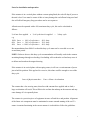
1
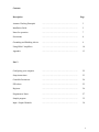
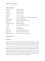
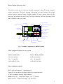
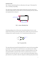
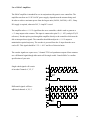
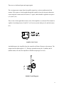
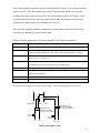
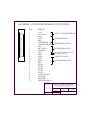
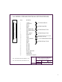
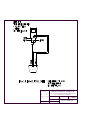
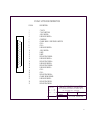
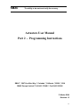
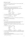
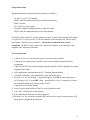
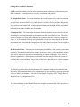
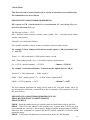
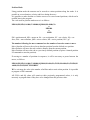
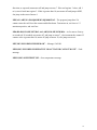
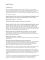
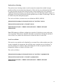
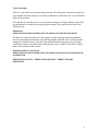
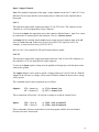
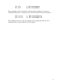
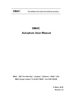
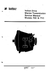
SMAC The ability to do work and verify its accuracy SMAC Actuator User Manual SMAC 5807 Van Allen Way Carlsbad California 92008 USA SMAC Europe Limited Tel 01403 276488 Fax 01403 256266 P. Marks 08.00 Revision 1.5 Contents Description Page Actuator Working Principals ………………………………………………. 3 Installation Guide ………………………………………………. 5 Notes for operation ………………………………………………. 7 Precautions ………………………………………………. 8 Grounding and Shielding Advice ………………………………………………. 9 Using SMAC Amplifiers ………………………………………………. 10 Appendix ………………………………………………. 13 Configuring your computer ………………………………………………. 22 Setup instructions ………………………………………………. 23 Controller Parameters ………………………………………………. 24 PID values ………………………………………………. 25 Registers ………………………………………………. 26 Programmers Notes ………………………………………………. 27 Sample program ………………………………………………. 32 Input / Output Channels ………………………………………………. 38 Part 2 2 Actuator Working Principles Actuator Components Moving Coil . . . . . . Powers linear motion Linear guide . . . . . . Guides linear motion Bumpers . . . . . . Adjustable end stops . . . . . End of stroke sensors Limit Switch Thermistor . . . . . . Detects overheating Piston . . . . . . . . Carries coil, rod and DC motor. Mounted to linear bearing Bearing/Bushing . . . Guides rod through body Optical encoder . . . . Measures distance travelled by piston Glass Scale . . . . . . Optical encoder scale Encoder detector head . . Reads the optical scale Index line . . . . . . . . Locates a fixed position on the scale DC motor . . . . . . . . Rotates the rod Gearbox . . . . . . . . Connects motor to rod Rotary encoder . . . . . Measures angular distance traveled Rotary index . . . . . . Locates a fixed position on the scale Rotary Coarse Index . . Proximity switch to detect rotary home Method of operation Linear Motion The piston rides on a linear bearing carriage, which slides on the linear guide rail. A copper coil is mounted on the piston. This coil rides inside a magnet assembly. When current flows in the coil, a reaction force is produced causing the piston to slide along the guide. Bumpers are set at each end of the travel to cushion any impact force that may occur. Flags carried by the piston activate limit switches before the end of travel is reached. Either the glass scale of the optical encoder or the reader head is carried by the piston. As the piston moves, the detector head reads the distance traveled. An index line on the glass scale is used as a home location. The actuator rod exits the body through the bearing to maintain alignment. A thermistor is present in the actuator to signal an overheating condition. 3 Rotary Motion (LAR series only) The piston to rotate the rod carries an assembly comprising a rotary DC motor, magnetic encoder, and gearbox. The rod is mounted to the piston in a rotary bearing. The rod and gearbox shaft are connected using a flexible coupling. To locate a home position for the rotary axis, the actuator rod carries a flag. This flag is sensed by a reflective proximity switch and is identified as the coarse index. MAGNET HOUSING 25 PIN D CONNECTOR MOVING COIL THERMISTOR MAIN CONNECTOR BOARD LIMIT SWITCHES COARSE HOME SENSOR ENCODER READER HEAD GLASS SCALE MOUNTING RIBBON CABLE DC ROTARY MOTOR SHAFT O-RING SEALS COARSE HOME FLAG FLEX COUPLING GEARBOX VACUUM TUBE Fig 1. Actuator Components (LAR30-15 shown) SMAC equipment required to run a system Linear Actuator only: Linear / Rotary Actuator: LAL series actuator LAR series actuator LAC – 1 Controller LAC – 25 controller LAH-LO(D)-03 Cable LAH-RT(D)-03 cable Other equipment required RS232 cable and connector (appendix page 1) Laptop PC or text editor to construct program (see setup instructions) 26 pin I/O connector for Input/ Output channels Either 24 Volt D.C., 4 Amp Power supply (30, 37, 50 series) Or 48 Volt D.C., 4 Amp Power supply (90, 300 series) 4 Installation Guide Note: Customers manufacturing their own cables please refer to page 7 of this manual for advice on shielding and grounding. The actuator must be mounted using the tapped mounting holes provided, and users must ensure that mounting surfaces are flat in order to prevent any distorting of the body when the unit is tightened down (see Figure 2). RAISED MOUNTING SURFACE TAPPED HOLES AND DOWEL POINTS RAISED MOUNTING SURFACE TAPPED HOLES AND DOWEL POINTS Fig 2. Actuator Mounting Points If attaching anything to the rod of the actuator using the threaded part of the rod, use the spanner flats provided to prevent the rod rotating. Do this with the rotary motor powered off as damage may be caused to the gearbox if it is overloaded (turned with the power on). 2x FLATS Fig 3. Use spanner flats The actuator housing and controller housing should both be connected to the same grounding point (Earth). This is usually the case when the units are screwed directly onto a machine chassis. If they are not screw-mounted then a ground wire should be attached to each of the units and this should be connected to Earth. As these are anodized it may be necessary to attach the wire to one of the steel screws, or to put a small scratch on the housing to ensure a good connection. It is possible to connect the components to different ground points, but they 5 must be at the same voltage level. Failure to do this may cause a current to flow from one point to another and this may result in noise. AC power usually generates the operating voltage (e.g. 24v), which is DC and is isolated (not connected to earth). The power supply has two terminals, 24v and 0v. This operating voltage is used to generate a 5v DC reference voltage. This also has two terminals 5v and 0v. These two 0v terminals are connected together but still isolated from earth. The system will work if these are not connected to earth but problems may arise when the RS232 is connected. The RS232 ground is connected to the 0v connection in the controller. When it is connected to a PC, the ground wire is then connected to earth. If this causes problems the following actions will help: - Plug the power supply to the same AC outlet as the PC - Connect the 0v terminal to Earth Note - the 0-volt terminal of the controller is connected to the metal shield of the connector. As this is screwed into the controller housing, the 0 volt is then effectively connected to Earth when the controller housing is grounded. Therefore it is not usual to see a problem when connecting a PC to the controller. RS232 CONTROLLER P.C. ACTUATOR AC OUTLET RTN POWER SUPPLY +24V Fig 3. Grounding layout 6 Notes for installation and operation If the actuator is in a vertical plane without a return spring fitted, the rod will drop if power to the unit is lost. Users must be aware of this as it may damage the end-effector being used and also will affect Emergency Stop procedures and re-set sequences. All units must be operated with a 40% maximum duty cycle, this can be calculated as follows: % of max force applied e.g. 100% force 60% force 40% force x % of cycle time it is applied x 40% of cycle time = x 50% of cycle time = x 100% of cycle time = = % duty cycle 40 % duty 30 % duty 40 % duty Recommendations from SMAC are that this duty cycle must not be exceeded over a one second time period. NOTE: Failure to observe this duty cycle recommendation will usually result in the actuator sustaining damage through overloading. Overloading will overheat the coil and may cause it to deform and touch on the magnet housing. If the actuator is in vertical plane with no spring return, it will use a certain amount of power just to hold its position. If the payload is excessive, this alone could be enough to exceed the duty cycle. Laws of physics state that : Force = Mass x Acceleration The actuator has a low moving mass, therefore with constant force applied and no load, a large acceleration will result. This will drive the rod into the endstop on the actuator and may cause damage if it is repeatedly done. The actuator is a precision piece of equipment in terms of both force and position. Alignment of the linear axis components must be maintained to ensure smooth running of the rod. To ensure it remains functioning in the correct manner it is advisable to follow the guidelines. 7 Precautions: Handle the actuator carefully, do not drop it or subject it to excessive shock loading Do not apply excessive side loads to the rod, this can lead to increased friction and wear on the internal components Avoid putting the actuator in hazardous environments such as wet, dusty, very hot (>50° C), very cold (<0° C). Consult SMAC if the actuator is required to work in these environments. Other points to note: - Use the optical index to home the actuator on a regular basis, this is especially important when the actuator is being moved around on another axis, or subject to vibration. - Avoid powering the rod into the endstops (this is also related to duty cycle) - Get familiar with the actuator by first using it on a horizontal surface with no load and limited force 8 Shielding and grounding advice (for customers manufacturing their own cable) Note: Using non-SMAC cables will invalidate the warranty unless an SMAC engineer checks the cable. Shielding Noise from wires carrying the coil power needs to be prevented from leaking out – these wires need to be twisted pairs held inside a shielded cable. Encoder signals need to be shielded from noise – these should also be twisted pairs held inside a separate shielded cable. The shield should cover as much of the wire it is shielding as possible. This means that the encoder signals shield should start as close to the encoder detector circuit as possible and terminate as close to the controller connector as possible. The shield for the coil power lines should follow the same pattern. The shield must therefore cover the whole distance between actuator and controller. For the shields to work they must be connected to a noise free connection, the closer this is to the input the better. This means that for the encoder signal cable the shield should be connected to the 0v terminal of the operating voltage at the controller connector. The power cable shield should be connected to the actuator ground (Earth). Drawings are available on request from SMAC. 9 Use of SMAC Amplifiers The SMAC amplifier is intended for use in conjunction with generic servo controllers. The amplifier runs from an 11-50 Volt DC power supply, dependent on the actuator being used. In order to achieve maximum power from the largest units (LAL90, LAL300), a 48V, 5Amp DC supply is required, otherwise 24V, 5 Amp DC is used. The amplifier takes a +/- 10 V signal from the servo controller, which is used to generate a +/- 3 Amp output to the actuator. This input is connected to pins 13 (+/- 10V), and pin 25 (0V reference). Encoder pulses pass through the amplifier directly to the controller which must be able to interpret these signals. The controller should then adjust its +/- 10 V output to maintain the required trajectory. The encoder is powered from the 5v input from the servo card or PC. This signal should be 5.1V +/- 0.1V and free of electrical noise. The encoder signals are square wave, 3 channel TTL level quadrature outputs. Most actuators use a differential signal though older units will be single ended. Consult SMAC to confirm specification of your unit: Single ended signals will consist of encoder Channels A+, B+, I+. Differential signals will have additional channels A-, B-, I-. 10 There are two dedicated input and output signals. The overtemperature output from the amplifier signals an overheat condition inside the actuator. These pins are wired straight through the amplifier from the electronic thermistor circuit inside the actuator and will switch a 5v signal, which should be applied across pins 6 (+5v) and 7 (0v). There is also a fault signal that becomes active if the amplifier is overheated. This channel is capable of switching between 5 and 30 V at 10 mA across the fault pin (11) and fault return (23). Amplifier fault Circuit An inhibit input to the Amplifier from the controller will shut off power to the actuator. The output from the inhibit signal is 9 V. Placing a ground between pins 12 (inhibit) and 24 (inhibit return) will cause the amplifier to shutdown (output goes to zero): Inhibit Circuit Diagram 11 Limit switch signals are present on pins 8 (extend) and pin 9 (retract). The return pin for both of these is pin 10. They are normally open circuit. When the limit switch is activated, the resistance across these pins will go to 7kΩ. This can be used to switch a 24V signal. A pullup resistor may be necessary across the supply to these pins, measuring across the resistor will show the voltage going to zero when the limit is active. The case of the amplifier should be connected to a ground point to reduce the effect of any electrical noise that may be present in the system. Diagrams of pin assignments for wiring the amplifier can be found in Appendix 1. Pin Number Description of connections 1,2 1=+5v, 2=+5v rtn -- 5v input from controller, often 5v from PC is used. 5.1v +/- 0.1v 3,4,5 14,15,16 3,4,5 = A,B,I encoder signals, 14,15,16 = A-,B-,I- signals. Encoder signals from actuator pass through amplifier to the controller. Max operating current = 140mA. 6,7 6 = overtemp, 7=overtemp rtn. A 5v 10mA current limited signal can be switched across pin 6 (+5v) and pin 7 (0v). 8,9,10 8=limit+,9=limit-,10=limit rtn. Pull-up resistor required 5 kΩ. Applying a voltage and measuring across the resistor will show 0v when limit is active. 11,23 11=fault, 23=fault rtn. Can switch up to 30V 10mA signal when active. 12,24 12=inhibit, 24=inhibit rtn. Connecting inhibit (pin 12) to ground (pin24) will inhibit the output from the amplifier. 13,25 13= +/- 10v command signal, 25=0v reference for signal. Other pins Not used If a 24V fail safe limit signal is required (Active limit = 0V), the following circuit can be used + 5V 0v 5.1k 10 LIMIT RTN 5.1k 9 8 LIMIT - LIMIT + REED RELAY, 5v RS PART NUMBER 291-9675 (TOP VIEW) PLC INPUT REED RELAY, 5v RS PART NUMBER 291-9675 (TOP VIEW) PLC INPUT 0V +24 V 0V +24 V Limit Switch signal to 24V 12 SMAC The ability to do work and verify its accuracy Appendix 1 Diagrams 13 LAA-5 AMPLIFIER - ACTUATOR CONNECTOR, FEMALE (OUTPUT TO ACTUATOR) 1 14 25 13 PIN NO. DESCRIPTION 1 2 3 4 5 6 7 8 9 10 11 12 13 14 15 16 17 18 19 20 21 22 23 24 25 + 5 VOLT 5 VOLT RETURN PHASE A+ PHASE B+ INDEX + OVER TEMPERATURE OVER TEMPERATURE RETURN LIMIT + LIMIT - RETRACT LIMIT RETURN FAULT INHIBIT MOTOR + PHASE APHASE BINDEX NOT USED NOT USED NOT USED NOT USED NOT USED ROTARY COARSE HOME FAULT RETURN INHIBIT RETURN POWER RETURN FORM COIL TOLERANCES SCALE +/- 0.5 +/- 0.1 +/- 0.05 PASS THROUGH AMPLIFIER PASS THROUGH FROM ACTUATOR PASS THROUGH FROM ACTUATOR OUTPUT SHUTDOWN BIT OPEN COLLECTOR OPTO AMP ENABLE BIT, LED OF OPTO POWER TO ACTUATOR COIL PASS THROUGH FROM ACTUATOR SMAC EUROPE LIMITED (UNLESS STATED) X. = X.X = X.XX = 5 VOLTS TO ACTUATOR FROM CONTROLLER UNIT 6, CITY BUSINESS CENTRE, BRIGHTON ROAD, HORSHAM, RH13 5BA TEL. -- 44 1403 276488 MATERIAL PART NAME DATE TITLE 24/02/99 FAX: -- 44 1403 256266 DRAWN BY P MARKS ACTUATOR CONNECTOR LAA-5 AMPLIFIER - CONTROLLER CONNECTOR, MALE (INPUT FROM CONTROLLER) 13 25 14 1 PIN NO. DESCRIPTION 1 2 3 4 5 6 7 8 9 10 11 * 12 * 13 14 15 16 17 18 19 20 21 22 23 24 25 + 5 VOLT 5 VOLT RETURN PHASE A+ PHASE B+ INDEX + OVER TEMPERATURE OVER TEMPERATURE RETURN LIMIT + LIMIT - RETRACT LIMIT RETURN FAULT INHIBIT V. SERVO COMMAND PHASE APHASE BINDEX NOT USED NOT USED NOT USED NOT USED NOT USED ROTARY COARSE HOME FAULT RETURN INHIBIT RETURN V RETURN, SERVO COMMAND TOLERANCES * PIN 12 = OPTO ISOLATED INTPUT, MAX CURRENT IP = 80mA X. = X.X = X.XX = SCALE +/- 0.5 +/- 0.1 +/- 0.05 PASS THROUGH AMPLIFIER PASS THROUGH FROM ACTUATOR PASS THROUGH FROM ACTUATOR OUTPUT SHUTDOWN BIT OPEN COLLECTOR OPTO AMP ENABLE BIT, LED OF OPTO +/- 10 VOLT COMMAND FROM CONTROLLER PASS THROUGH FROM ACTUATOR SMAC EUROPE LIMITED (UNLESS STATED) * PIN 11 = OPTO ISOLATED OUTPUT, MAX CURRENT IC = 50mA 5 VOLTS FROM CONTROLLER SUITE GA, BISHOPS WEALD HOUSE, ALBION WAY, HORSHAM RH12 1 AH TEL. -- 44 1403 276488 MATERIAL PART NAME DATE TITLE 24/02/99 FAX: -- 44 1403 256266 DRAWN BY P MARKS CONTROLLER CONNECTOR 15 TOLERANCES SMAC EUROPE LIMITED (UNLESS STATED) X. = X.X = X.XX = SCALE +/- 0.5 +/- 0.1 +/- 0.05 UNIT 6, CITY BUSINESS CENTRE, BRIGHTON ROAD, HORSHAM, RH13 5BA TEL. -- 44 1403 276488 MATERIAL PART NAME DATE TITLE FAX: -- 44 1403 256266 DRAWN BY P MARKS RS 232 CONNECTION 25-WAY ACTUATOR CONNECTOR 13 25 14 1 PIN NO. DESCRIPTION 1 2 3 4 5 6 7 8 9 10 11 12 13 14 15 16 17 18 19 20 21 22 23 24 25 5 VOLTS 5 VOLTS RETURN AXIS 2 MOTORLINEAR ENCODER AOVERTEMP COARSE HOME / OVERTEMP / LIMIT RTN COIL + COIL + LINEAR ENCODER BAXIS 2 MOTOR + LIMIT + LIMIT ROTARY ENCODER BLINEAR ENCODER A+ ROTARY ENCODER A+ LINEAR ENCODER B+ ROTARY ENCODER B+ LINEAR ENCODER I+ COIL COIL ROTARY ENCODER ACOARSE HOME SENSOR LINEAR ENCODER IROTARY ENCODER I+ ROTARY ENCODER ITOLERANCES SMAC EUROPE LIMITED (UNLESS STATED) X. = X.X = X.XX = SCALE +/- 0.5 +/- 0.1 +/- 0.05 UNIT 6, CITY BUSINESS CENTRE, BRIGHTON ROAD, HORSHAM, RH13 5BA TEL. -- 44 1403 276488 MATERIAL PART NAME DATE TITLE 24/02/99 FAX: -- 44 1403 256266 DRAWN BY P MARKS ACTUATOR CONNECTOR 17 SMAC The ability to do work and verify its accuracy Actuators User Manual Part 2 - Programming Instructions SMAC 5807 Van Allen Way Carlsbad California 92008 USA SMAC Europe Limited Tel 01403 276488 Fax 01403 256266 P. Marks 08/00 Revision 1.5 21 Configuring your Computer To communicate with SMAC controllers, any text editor can be used. Normally a laptop running Windows 3.1 or Windows 95/NT is used. Windows 3.1 1. 2. 3. 4. 5. 6. 7. 8. In program manager, select accessories window, double click on ‘Terminal’ If previously configured, open SMAC.trm and jump to step 8. Otherwise select settings from the pull down menu and click on communications. Setup as follows: Baud Rate - 9600 Data Bits -8 Stop Bits -1 Parity - None Flow control - Xon/Xoff Connector - COM1 Click ‘OK’ Select settings from the pull down menu and click on Text Transfers. Setup as follows: Flow control - Line at a time Delay between lines - 2/10 sec Save as SMAC.trm. With power to the controller, pressing the ‘esc’ key should give a greater than sign (>) indicating the unit is communicating properly. Windows ’95 or NT 1. Select programs, accessories then Hyperterminal. Double click on Hypertrm icon. If SMAC.trm has previously been setup, click this icon and jump to step 8. 2. Enter name for program (e.g. SMAC.trm) and choose an icon, click ‘OK’ 3. Phone number window will appear. In ‘connect using’ window, choose Direct to COM1, click ‘OK’. 4. COM1 properties will appear – set as follows: Bits per second - 9600 Data Bits -8 Parity - None Stop Bits -1 Flow Control - Xon/Xoff Click ‘OK’ 5. Select file from pull down menu, select properties, choose settings in properties window. 6. Click on ASCII setup, set line delay to 250ms, click on ‘wrap lines that exceed terminal width.’. Click ‘OK’. 7. Select file from pull down menu and save. 8. With RS232 connected and power to the SMAC unit, pressing the ‘esc’ key should display a greater than sign (>). 22 Set-up instructions Equipment needed to program and run an actuator is as follows: - An LAC-1 or LAC-25 controller SMAC cable for connection between controller and actuator SMAC actuator 24v or 48v DC power supply. Personal Computer running windows or other text editor. RS232 cable for connection between PC and controller. The SMAC cable consists of a D-sub connector (usually 25 pin) at the actuator end and either a 15 pin (LAC-1) or 26 pin (LAC-25) D-sub connector at the controller end. There is also a green plastic ‘Phoenix’ power connector – ensure this is connected in the correct orientation. The RS232 cable consists of a 9 pin D-sub connector at one end and a 6 pin telephone type connector at the other. To start the system 1. Connect J1 (26 or 15 pin) and green power connector to the controller. 2. Connect the 24v supply to the controller. Refer to the controller manual for the pin assignments. 3. Connect the RS232 between the computer and the controller. Refer to appendix for wiring diagram for this cable. 4. Select appropriate communication on PC. (Terminal, Hyperterminal) 5. Check all connections, when satisfied all is OK, turn on the power. 6. Press the ‘esc’ key, the prompt’>’ sign should appear. Type MF to ensure the motor is off. If using a LAC-25, type 0MF. (Note – typing 0MF on a LAC-1 controller will cause the controller to hang up. Re-power if this occurs). 7. Connect the 25 pin to the actuator. 8. Select Transfer menu and Send Text File, select program to send. 9. Type TM-2 (Tell Macros) to list program. 10. Type MS0 (Macro Sequence) to run the program. 11. Press the ‘esc’ key to stop the program, MF may need to be typed to turn the motor off if the program is stopped in mid sequence. 23 Setting the Controller Parameters A PID control algorithm is used to ensure optimum response behavior of the actuator to its input commands – reducing errors in velocity, acceleration and position. P = Proportional Gain – This term determines the overall response of a system to position errors, providing an output signal proportional to the error at any time. A low Proportional gain provides a system which is very stable (doesn’t oscillate), has low stiffness and possibly large position errors under load. A high proportional gain provides high stiffness and small positional errors under load, but may be unstable. I = Integral Gain – This term helps the system eliminate positional errors caused by friction or loading by increasing the output to the actuator until the error reduces to zero. The error is added or integrated over time and eventually the controller generates a sufficient output to reduce it. A low Integral Gain may allow positional errors at rest, which depend on the static or frictional loads. Increasing the Integral gain will reduce these errors but if it is too high, the system may ‘hunt’ or oscillate at low frequency about the desired position. D = Derivative Gain – This term provides damping and stability to the system by preventing overshoot. The controller analyses the change in error over time, in effect predicting what the error will be at the next time interval and adjusting the output accordingly. A low value of derivative gain allows a fast response to positional errors but may also allow the system to overshoot the desired condition. Large values of derivative gain will cause a slower response but may allow a higher proportional gain to be used without the system oscillating. The SMAC controller allows the Proportional (SG command), Integral (SI command) and Derivative (SD command) values to be programmed. It is also possible to program associated values to enhance performance – Derivative Gain Sample Frequency (FR), Sample Rate of Integral Gain (RI), Integral Limit (IL). The values tabulated overleaf should be used to setup the system initially. These may have to be adjusted to suit differing loading conditions, actuator orientations etc. 24 PID values for SMAC Actuators Note: These are starting values only, they may need to be adjusted for different load values or actuator orientations. Values should work with both LAC-25 and LAC-1 For 0.5µ and 0.1µ, reduce all values by a factor of 5 (e.g. SG25 becomes SG5) Linear Encoder 1µ 5µ 1µ 5µ 1µ 5µ 1µ 5µ 1µ 5µ 1µ 5µ 1µ 5µ Actuator LAS24 LAS24 LAL30 / LAR30 LAL30 / LAR30 LAL37 / LAR37 LAL37 / LAR37 LAL50 / LAR50 LAL50 / LAR50 LAL90 / LAR90 LAL90 / LAR90 LAL90-50 LAL90-50 Grippers LAL300 Rotary Standard 1Nm LAR 30/37/50 LAR90 Proportional (SG) 20 50 25 125 30 120 30 120 30 60 25 60 40 70 Integral (SI) 20 50 50 130 50 200 150 300 50 400 50 100 40 300 Derivative (SD) 400 600 350 700 400 1200 400 1600 400 1200 300 600 500 1500 Integral Limit (IL) 5000 5000 5000 5000 5000 5000 5000 5000 5000 5000 5000 5000 5000 2000 150 20 200 200 1500 300 5000 1500 It will also be necessary to program the following values. These values are nominal and can be changed to suit the motion profile as required during the program. Command Mnemonic Value Derivative Sampling Frequency Integration Limit Phase Sampling rate of integral Set Acceleration Set Velocity Set torque Set Servo speed Set following error FR IL PH RI SA SV SQ SS SE 1 5000 0 1 1000 30000 32767 2 16383 These values can be displayed at any time by typing the TK (tell constants) command. Note that changing the SS command will alter the SV and SA values produced, as these are dependent on the clock speed. 25 Registers Part of the non-volatile memory (NVRAM) of the controller is used to create a 256 by 32 bit register space. This means that variables can be stored, updated and retrieved during execution of a program. It is possible to store 32 bit numbers in any of the 255 registers. Register 0 is referred to as the accumulator, this is regarded as a temporary store for variables. The code required to store a number is as follows: AL10000,AR220 Accumulator Load value 10000, Accumulator to Register 220 This will store a value of 10000 to register number 220. Typing the command TR220 (Tell Register 220) will display 10000 (the contents of register 220) on the screen. The command MA@220,GO would now be the same as typing MA10000,GO, the @ symbol shows that a register value is to be used. Registers could, for example, be used to set up a counter to record the number of cycles carried out by the actuator. We would increase the value in a register by one each time a cycle is completed. RA50,AA1,AR50 Register to Accumulator 50, Accumulator Add 1, Accumulator to Register 50. If we execute these commands each time we complete a cycle, the value in register 50 will be increased by one each time. Preset Variables There are areas in memory allocated to preset internal variables. It is possible to access these values at any time during execution of a program. This is important during such routines as a soft land (measure) routine, homing routine and for safety or damage checks during the cycle. We can access such variables as position error, position, input values. For example to access the current position of axis 1, type RL494 (Read Long word at address 494 to accumulator), this will transfer the current real position into the accumulator. The command TR0, (Tell Register 0 – i.e. the accumulator) will display this value on the screen. There is a comprehensive explanation of all these functions, along with a list of preset variables on pages 44-51 of the LAC-25 manual, or pages 41-48 of the LAC-1 manual. 26 Programmers Notes The controllers supplied by SMAC use a programming language similar in structure to assembler code. The code is held in non-volatile RAM in the controller. The language consists of two letter commands followed by a number, e.g. MN = Motor On, PM = Position mode. Programs are constructed using lines of code known as Macros, these are numbered and the program can be commanded to execute different macros, call subroutines and jump to different points dependant on conditions. An example of macros might be: MD10,QM,MN,SQ10000,MJ20 MD20,WA1000,MF MD = MN = MJ = MF = Macro Definition Motor On Macro Jump Motor off QM = Force mode SQ = Set Force WA = Wait Notes: Macros are started by typing MS (macro sequence) followed by the number of the first macro to be executed On power up of the unit the program will execute Macro 0 automatically. Macros will continue to execute if they are in numerical order, otherwise an MJ command is required. Default values are usually 0, check controller manual for full list of defaults. LAC-25 controllers need to have an axis address (e.g. 1MN = Axis 1 Motor On, 2MN = Axis 2 Motor On, 0MF = Axis 1 and Axis 2 Motor Off) (Note that with an LAC-1 controller these axis labels are not needed and will cause a fault. A re-power of the unit is necessary in this case) Getting Started SMAC systems consist of a controller, cable and actuator. The controller generates movement of the actuator as commanded by the software. A current is output to the coil of the actuator; this provides the driving force for the system. Position of the actuator piston is continually fed back by the linear encoder; this is monitored by the controller. When the actuator is commanded to make a move through software, a trajectory is calculated for the move. The position of the actuator piston is monitored over time by the controller, and the force output is controlled to match the actual movement to the required movement. The difference between the actual position and required position is known as the position error. The controller will try to reduce the position error to zero at any time. It is also possible to use the actuator without this feedback facility, the unit can run ‘openloop’, ignoring the encoder feedback. The controller will generate a current through the coil, which produces a constant force on the end of the rod. If there is no resistance to movement, the rod will accelerate due to the applied force. Refer to the ‘Actuator User Manual’ for details of setting up system hardware. 27 Programming modes There are three methods with which the actuator can be commanded to move - force mode, velocity mode and position mode. As follows: Force Mode Force mode is open loop, using no feedback from the encoder. Actual position is still monitored but has no effect on the output. The commands that are used are as follows: MD100,MN,QM0,SQ32767 MN = motor on, QM = force mode, SQ = set force. The range of values for the SQ command are from –32767 to +32767, corresponding to maximum force in positive (extending the rod) or negative (retracting) directions. This will generate an output from the PWM amplifier inside the controller. The output is almost linear, though towards the higher end of the scale there will be more energy lost through heat generation inside the coil, effectively reducing the force generated. QM0 uses PWM to generate an output to the coil. QM1 is a more accurate method to generate a force using one of the Analogue Input channels to monitor the actual current running through the coil. The commands for this method of programming would be as follows: MD100,SC2000,MN,QM1,SQ500 SC = set current gain, MN = motor on, QM = force mode, SQ = set force. Note that the SC value will need to be programmed to allow feedback to be monitored and outputs modified. The range of values for the SQ command are from –1023 to +1023, corresponding to a +/- 5 Amp output generated from the controller. The maximum current that is used in the coil of the actuator is +/- 3 Amp, therefore the maximum value would be SQ-600 to SQ600. Anything above SQ600 would have no effect on the current passing through the coil. This allows us to calculate the resolution of the actuator output Resolution = max force / 600. For a 100N unit: Resolution = 100N / 600 = 0.16 N This resolution is effective whether we work in QM0 or QM1. 28 Velocity Mode This allows the rod to be moved with a given velocity, acceleration, force and direction. The commands to use are as follows: MD100,MN,VM,SA1000,SV100000,SQ10000,DI0,GO MN = motor on, VM = velocity mode, SA = set acceleration, SV = set velocity, SQ = set force, DI = direction, GO = go The SQ range is from 0 – 32767. DI0 = direction which increases encoder count (extend), DI1 = direction which reduces encoder count (retract). SA and SV are calculated as follows: The controller calculates velocity in terms of encoder counts per update period: For example: Velocity 10mm/s with 5 micron encoder, update = 200 µ s (standard LAC1 / LAC-25) 10 mm / s x 200 (counts/mm) = 2000 encoder counts / second 2000 / 5000 (update periods / sec) = 0.4 encoder counts per update period 0.4 x 65536 (internal constant) = SV26214 ∴ 10mm/s = SV26214 For example: Acceleration 100 mm/s2 , 5 micron encoder, update period = 200 µ s 100 mm/s2 x 200 (counts/mm) = 20000 counts/s2 20000 / 50002 (update periods / s2) = 0.0008 counts / update period2 0.0008 x 65536 (constant) = SA52 ∴ 100 mm/s2 = SA52 The most common application for using velocity mode is the ‘soft land’ routine, where we use the actuator to land with a controlled force onto a component. The commands we use for this are as follows; MD100,MN,VM,SA1000,SV50000,SQ5000,DI0,GO,WA50 MD101,RW538,IG50,MG”LANDED”,MJ105,RP MD105,TP,MF,EP MD100 – Starts the actuator moving in a positive direction with limited velocity and force. MD101 – Word 538 is the address for the position error, if greater than 50 (IG50) the next two commands are executed i.e. the message is displayed and the program jumps to MD105. Otherwise these commands are ignored and the RP (repeat) command is executed, which repeats the macro. MD105 – Tell Position will display the current position, Motor off, End Program. 29 Position Mode Using position mode the actuator can be moved to various positions along the stroke. It is possible to set acceleration, velocity and force during the move. It is possible to make absolute or relative moves or to store learned positions, which can be recalled later in the program. The code used for position mode moves is as follows: MD100,PM,MN,SA1000,SV100000,SQ20000,MA1000,GO or MR1000 or MP20 PM = position mode, MN = motor on, SA = set acceleration, SV = set velocity, SQ = set force, MA = move absolute, (MR = move relative, MP = move position) GO = go The number following the move command are the number of encoder counts to move. Move Absolute will move the rod to an absolute position from the defined zero position. Move Relative will move the rod a relative distance from the current position. Move Position will move the rod to a previously defined position (requires a learned position LP command to store the position). If moving to a number of positions in sequence, it will be necessary to pause between the moves, as follows: MD100,PM,MN,SA1000,SV100000,SQ20000,MA100,GO,WS20,MA1000,GO,WS500,M A4000,GO,WS50,MG”FINISHED” WS = wait stop, the value is the number of milliseconds to wait at that position. It is possible to program a WS0 command. All SV,SA and SQ values will remain at their previously programmed values, it is only necessary to program them if they have to be changed from the previous value. 30 LOOK-UP TABLE FOR VELOCITY / ACCELERATION VALUES (USING LAC-1 / LAC-25, UPDATE RATE = 200 µs) 5 MICRON ENCODER 1 MICRON ENCODER VELOCITY (mm/s) SV VALUE VELOCITY (mm/s) SV VALUE 1 5 10 15 20 50 100 200 500 1000 2000 2621 13107 26214 39322 52429 131072 262144 524288 1310720 2621440 5242880 1 5 10 15 20 50 100 200 500 1000 2000 13107 65536 131072 196608 262144 655360 1310720 2621440 6553600 13107200 26214400 ACCELERATION (mm/s/s) SA VALUE ACCELERATION (mm/s/s) SA VALUE 10 50 100 150 200 500 1000 2000 5000 10000 20000 5 26 52 79 105 262 524 1049 2621 5243 10486 10 50 100 150 200 500 1000 2000 5000 10000 20000 26 131 262 393 524 1311 2621 5243 13107 26214 52429 31 Sample Program – Testing the Encoder in a Program Before the actuator can be moved, the encoder must be tested. If it is not tested and a fault is present, a large position error could build up. This would then cause a large output signal to be generated, resulting in rapid movement and crashing of the actuator into the end stops. ; ENCODER TESTING ROUTINE ; MF,RM ; MD0,MF,PM,SQ32767,CF0,CF1,CF2,CF3,CF4,CF5,CF6,CF7,DH,AL1,AR3 MD1,AL254,LV27,EV27 MD2,FR1,SG@5,SI@6,SD@7,IL5000,SC2000,RI1 MD3,QM,MN,SQ-10000,WA5 MD4,RL494,IB-10,MF,MJ7,RA3,AA1,AR3,IG10,MF,MJ5,MJ4 MD5,AL1,AR3,WA200,SQ0,DH,MN,SQ10000,WA5 MD6,RL494,IG10,MF,MJ7,RA3,AA1,AR3,IG10,MF,MJ30,MJ6 MD7,MG”ENCODER CHECKED OK” MD30,MG”ENCODER INOPERATIVE OR ACTUATOR CANNOT MOVE” ; ENCODER TESTING ROUTINE – The controller ignores anything after the semicolon. Comments etc. can be placed here. MF,RM – Motor off, reset macros clears the memory. MD0,MF,PM,SQ32767,CF0,CF1,CF2,CF3,CF4,CF5,CF6,CF7,DH,AL1,AR3 – Motor off, enter position mode reset force limit to maximum, turn off all channels, define home. Initialize a counter in register 3 and set it to 1 at the start. MD1,AL254,LV27,EV27 – Load value 254 into vector 27 (overtemp). Enable vector 27. MD2,FR1,SG@5,SI@6,SD@7,IL5000,SC2000,RI1 – This sets up the PID constants. The gain, integral and derivative are in registers 5, 6 and 7. These values will need to be loaded before the program is run. MD3,QM,MN,SQ-10000,WA5 – Select torque mode, set force to one third maximum negative value, wait 5ms MD4,RL494,IB-10,MF,MJ7,RA3,AA1,AR3,IG10,MF,MJ5,MJ4 – Read axis 1 current position, if below –10 counts (i.e. the rod has moved more than 10 counts in a negative 32 direction, as expected) turn motor off and jump to macro 7. Else read register 3 value, add 1 to it, store it back into register 3. If this is greater than 10, turn motor off and jump to MD5, else jump to the start of macro 4. MD5,AL1,AR3,WA200,SQ0,DH,MN,SQ10000,WA5 – The program jumps here if it cannot retract the rod. Reset the counter and define home. Turn motor on, set force to 1/3 maximum positive, and wait 5ms. MD6,RL494,IG10,MF,MJ7,RA3,AA1,AR3,IG10,MF,MJ30,MJ6 – As for macro 4 but try to extend rod. If extended, turn motor off and jump to macro 7, else increment the counter. If counter value is greater than 10, motor off jump to macro 30, else jump to macro 6. MD7,MG“ENCODER CHECKED OK” – Message if all OK. MD30,MG“ENCODER INOPERATIVE OR ACTUATOR CANNOT MOVE” – Fault message. MD254,MG“OVERTEMP”,MF – Over-temperature message. 33 Sample Routines Softland Routine This routine enables the actuator to land on a surface with a low force, for example to measure a component. This is done in velocity mode, monitoring the position error as the rod is moving with a controlled force. It is also possible to set a position window where the component should be located, if it is not located within a certain position, the rod will retract. The code used is as follows: MD100,VI”PRESS ENTER TO START ”:99,VM,MN,SQ5000,SA1000,SV50000,DI0,GO,WA20 MD101,RW538,IG20,MG”FOUND”,MJ105,RL494,IG5000,MG”TOO FAR”,MJ110,RP ; MD105,ST,MG”POSITION = “:N,TP,MJ110 ; MD110,PM,MN,SA5000,SV500000,GH,WA50,SQ32767,WS100,MJ100 MD100,VI“PRESS ENTER TO START ”:99,VM,MN,SQ5000,SA1000,SV50000,DI0,GO,WA20 This line waits for a carriage return to be entered via the RS232 port by using the variable input (VI) command. Then the unit enters velocity mode (VM), motor on (MN) and sets constants - force (SQ), acceleration (SA), and velocity (SV). Direction 0 (DI0) commands the rod to move in a direction which increases the encoder count. WA20 allows any initial error to disappear before the program starts checking position error. MD101,RW538,IG20,MG“FOUND”,MJ105,RL494,IG5000,MG“TOO FAR”,MJ110,RP The position error is checked (RW538), if it is greater than 20 encoder counts, display message and jump to MD105. Else read actual position (RL494), if greater than 5000 counts, display message and jump to MD110 MD105,ST,MG“POSITION = ”:N,TP,MJ110 Stop motion, display message (:N means no carriage return after message), Tell Position then jump to MD110. MD110,PM,MN,SA5000,SV500000,GH,WA50,SQ32767,WS100,MJ100 Enter position mode, set acceleration and force higher. Issue the go home (GH) command but wait 50ms before ramping force up to maximum. This is needed because if the force is increased immediately then any position error will be taken up, possibly deforming the measured component. Wait after stop 100ms then jump back to MD100. Notes: If the actuator is in vertical orientation it will not be possible to land with a force less than the moving mass of the actuator with the above code. This is because when the controller sees a position error it will ramp up to the maximum allowable force in order to overcome that error (SQ5000 in this case). To overcome this situation, it would be desirable to limit the maximum force to a lower value (SQ500 for example) however it would not then be possible to control the motion of the actuator, the rod would just drop under its own weight. It is possible to assign values to the minimum and maximum forces used, allowing the motion of the rod to be controlled, but limiting the maximum force that will be applied. The addresses to be used are Word 582 (minimum SQ value e.g. -30000) and Word 534 (maximum SQ value e.g. 0). It is necessary to write values to these words from the accumulator using the WW instruction, these commands replace the SQ command. To put these values into the soft land routine, the code would be as follows: MD100,VI”PRESS ENTER TO START ”:99,VM,MN,AL-30000,WW582,AL0,WW534,SA1000, SV50000,DI0,GO,WA20 Note that these values would not work if the actuator were in horizontal because there is no force available to move the rod forward. 35 Position Error Checking The position error checking routine is used to ensure the actuator has reached its target position and has not encountered an obstruction. If the unit has not reached position there will be a large position error present which will cause a large restoring force to be generated within the actuator which may exceed the 40% duty cycle. The checking routine consists of a subroutine of two lines which checks that the position error is within a certain range. This can be called at any time during the program. The code is as follows: (Assume moves are defined on MD120, MD130) MD120,PM,MN,MA2000,GO,WS100,MC245,MG“AT POSITION”,MJ130 ; MD130,GH,WS100,MC245,MG“AT HOME”,MJ120 ; MD245,RW538,IG20,MG“+ ERROR”,MJ246,IB-20,MG“- ERROR”,MJ246,RC MD246,MF,EP Note: PID tuning may influence settling time at position. Payload may cause steady state error at position. These factors should be taken into account when choosing the amount of error to check for, and the time after the move before the check is carried out. Low Force at Home If the unit is at rest and the rod is disturbed by an external force, either another part of the system or manually by an operator, this will also cause a position error to be present. To avoid any damage it is useful to reduce the holding force at this rest position, therefore bringing the actuator to within its 40% duty cycle. The code is as follows: MD120,PM,MN,MA2000,GO,WS100,MC245,MG“AT POSITION”,SQ10000,MJ130 ; MD130,GH,WS100,MC245,MG“AT HOME”,SQ10000,MJ120 ; MD245,RW538,IG20,MG“+ ERROR”,MJ246,IB-20,MG“- ERROR”,MJ246,RC MD246,MF,EP 36 Vector interrupts There are some points to note when using interrupts. The main point is that the interrupts are only sampled when the program is executing commands. It is therefore wise to avoid absolute delays in the program. It is often the case that the unit is at a start position waiting for an input channel (from a PLC or push button for example) to start the program running. This could take the form of the following code MD100,WN2 MD101,PM,MN,SA1000,SV100000,SQ32767,MA3000,GO,WS100,GH,WS100,MJ100 The Wait On command would cause the program to stop executing until that condition is true. This means that the interrupts are not being sampled while the code is waiting for this condition. It would be better to use the If On command with the program in a loop which would allow checks to be made while at that position, also it would be advisable to add the other checks outlined in this section: MD100,IN2,MJ101,NO,MC245,RP MD101,PM,MN,SA1000,SV100000,SQ32767,MA3000,GO,WS100,MC245,GH,WS100,MC245, SQ10000,MJ100 ; MD245,RW538,IG20,MG“+ ERROR”,MJ246,IB-20,MG“- ERROR”,MJ246,RC MD246,MF,EP 37 Input / Output Channels Note: The method of operation of the input / output channels on the LAC-1 and LAC-25 are different. Please ensure that the correct instructions are followed for the controller that is being used. LAC-1 This unit has 8 inputs and 8 outputs operating at 5-volt TTL levels. The connector on the controller is a 26-way high-density d-type connector. To activate an input, the appropriate pin on the connector (labeled input 1, input 2 etc.) must be connected to a common pin on the connector. This is a volt-free contact. An output will be switched from 0 volts between output pin and common when in the off state, to 5 volts when on. If this has to be used to switch a 24V signal (on a PLC for example), a relay must be used (e.g. RS 291-9675). Refer to LAC-1 user manual for full specification on these signals. LAC-25 This unit has 4 inputs and 4 outputs operating at between 5 and 24 volts. The connector on the controller is a 26-way high-density d-type connector. To activate an input signal a voltage must be applied to the input pin, with the input return connected to ground. The output channels can be used to switch a voltage of between 5 and 24 volts dc. With the channel in the off state, no voltage will be passed. With the channel in the on state a voltage will be passed. The commands used for these operations are as follows: Outputs: CN = channel on CF = channel off e.g. CN1 = channel 1 on e.g. CF3 = channel 3 off These commands will activate / de-activate an output to switch an external device. Inputs: WN = Wait on WF = Wait off e.g. WN2 = wait on channel 2 e.g. WF0 = wait off channel 0 These commands will cause an absolute wait in the program until the relevant channel becomes activated / deactivated. 38 IN = If On IF = If Off e.g. IN0 = If on channel 0 e.g. IF6 = If on channel 6 These commands will act as a normal ‘if’ command. If the condition is true, the two commands following the ‘if’ statement will be executed, otherwise they will be ignored. DN = Do if On DF = Do if Off e.g. DN5 = Do if channel 5 on e.g. DF7 = Do if channel 7 off If the condition is true (on or off), the remainder of the command line after the ‘do if’ command will be executed, otherwise it will be ignored. 39