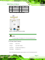
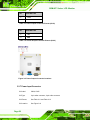
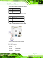
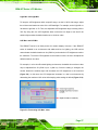
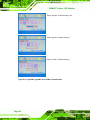
1
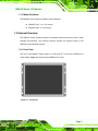
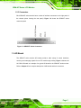
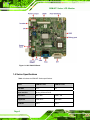
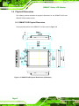
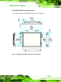
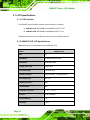
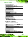
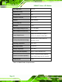
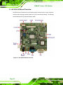
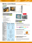
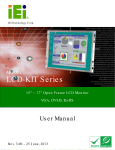
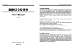
SRM-KIT Series LCD Monitor SRM-KIT LCD Monitor User Manual Page i SRM-KIT Series LCD Monitor Revision Title SRM-KIT LCD Monitor User Manual Revision Number Description Date of Issue 1.0 Initial release January 2007 Page ii SRM-KIT Series LCD Monitor Copyright COPYRIGHT NOTICE The information in this document is subject to change without prior notice in order to improve reliability, design and function and does not represent a commitment on the part of the manufacturer. In no event will the manufacturer be liable for direct, indirect, special, incidental, or consequential damages arising out of the use or inability to use the product or documentation, even if advised of the possibility of such damages. This document contains proprietary information protected by copyright. All rights are reserved. No part of this manual may be reproduced by any mechanical, electronic, or other means in any form without prior written permission of the manufacturer. TRADEMARKS IBM PC is a registered trademark of International Business Machines Corporation. INTEL is a registered trademark of INTEL Corporation. Other product names mentioned herein are used for identification purposes only and may be trademarks and/or registered trademarks of their respective owners. Page iii SRM-KIT Series LCD Monitor Packing List NOTE: If any of the components listed in the checklist below are missing, please do not proceed with the installation. Contact the IEI reseller or vendor you purchased the SRM-KIT from or contact an IEI sales representative directly. To contact an IEI sales representative, please send an email to [email protected]. The items listed below should all be included in the SRM-KIT package. 1 x SRM-KIT121G / SRM-KIT150G industrial LCD monitor 1 x 45W AC Power Adapter 1 x AC power cable 1 x DVI cable 1 x VGA cable 1 x Screw set 1 x User manual and driver CD Images of the above items are shown in Chapter 4.2.3. Page iv SRM-KIT Series LCD Monitor Precautions SAFETY PRECAUTIONS 1. Prior to installing, moving, and modifying the panel PC, make sure that the unit’s power is turned off and the power cord is disconnected. 2. Do not apply voltage levels that exceed the specified voltage range. Doing so may cause fire or an electrical shock. 3. Electric shock can occur if the panel is opened. Do not drop or insert any objects into the ventilation openings of the panel PC. 4. Only qualified engineers from certified system integrators or VARs are allowed to make necessary functional modifications to the panel PC, e.g., adding a touch screen. IEI offers the customization service on a pre-order basis. 5. If considerable amount of dust, water, or fluids entered the panel PC, turn off the power supply immediately, unplug the power cord, and contact the vendor. 6. Explosions may occur with installations in environments where flammable gases are present. 7. Fault-tolerant and failsafe designs should be implemented with the use of the series models on transportation vehicles, ships, safety/security devices, or medical devices not related to life-support functionalities. Users/integrators should take the responsibility for implementations with adequate levels of reliability and safety. 8. Preventive designs should be implemented so as to avoid the communications faults between the panel PC and the PC/workstation/terminals that controls it. 0. HANDLING PRECAUTIONS 1. Do not drop the panel PC against a hard surface. Doing so may damage the display. 2. Do not strike or exert excessive force onto the touch panel. 3. Touching the touch panel using a sharp object may damage the LCD panel. 4. Avoid environments exposed to direct sunlight, dust, or chemical vapors. 5. The panel PC is actively cooled. In no circumstances should the panel PC Page v SRM-KIT Series LCD Monitor operate with the openings obstructed by foreign objects. However, the ambient temperature of the installation site should be observed and controlled to avoid overheating the panel PC. 6. Condensation might form inside the panel PC chassis if exposed to sudden changes in temperature. 7. Carefully route the power cord so that people cannot step on it. Do not place anything over the power cord. 8. If the equipment should be left unused for an extended period of time, disconnect it from the power source to avoid damage by transient over-voltage. 9. If any of the following situations arises, get the equipment checked by service personnel: 0. o o o o The power cord or plug is damaged. Liquid has penetrated into the equipment. The equipment has been exposed to moisture. The equipment does not work properly, or the user cannot get it to work according to the user manual. o o The equipment has been dropped and damaged. The equipment shows obvious signs of breakage. WARNING! Any changes or modifications made to the equipment that are not expressly approved by the relevant standards could void the authority to operate the equipment. MAINTENANCE AND CLEANING Note the following precautions before beginning to clean the Panel PC. When cleaning any single part or component of the computer, please read and understand the details below fully. Except for the properly installed front LCD panel, never spray or squirt liquids directly onto any computer component. To clean the device, please rub it with Page vi SRM-KIT Series LCD Monitor a piece of dry and soft cloth or a slightly moistened cloth with the exterior casing. The interior of the Panel PC does not require cleaning. Keep fluids away from the Panel PC and the interior of it. Be cautious of the tiny removable components when using a vacuum cleaner to absorb the dirt on the floor. Turn the system off before cleaning up the Panel PC. Never drop any tiny objects through the openings of the Panel PC or get circuit board damp or wet. Be cautious of all kinds of cleaning solvents or chemicals when using it for the sake of cleaning. Some individuals may be allergic to the ingredients. Avoid any food, drink or cigarette around the Panel PC. CLEANING TOOLS Although many companies have created products to help improve the process of cleaning the computer and peripherals, users can also use household items to clean their computers and peripherals. Below is a list of items to use while cleaning the computer or computer peripherals. Please keep in mind that some components in the computer may only be cleaned using a product designed for cleaning that component, if this is the case it will be mentioned in the cleaning tips. Cloth - A piece of cloth is the best tool to use when rubbing up a component. Although paper towels or tissues can be used on most hardware as well, it is recommended to rub it with a piece of cloth. Water or rubbing alcohol – Moisten a piece of cloth a bit with some water or rubbing alcohol and rub it on the computer. Unknown solvents may be harmful to the plastics parts. Vacuum cleaner - Absorb the dust, dirt, hair, cigarette particles, and other particles out of a computer can be one of the best methods of cleaning a computer. Over time these items can restrict the airflow in a computer and cause circuitry to corrode. Cotton swabs - Cotton swabs moistened with rubbing alcohol or water are Page vii SRM-KIT Series LCD Monitor excellent tools for wiping hard to reach areas in the keyboard, mouse, and other locations. Foam swabs - Whenever possible it is better to use lint free swabs such as foam swabs. ESD PRECAUTIONS Observe all conventional anti-ESD methods while handling the components contained within the LCD should the need arise for adding a functionality. The use of a grounded wrist strap and an anti-static work pad is recommended. Avoid dust and debris or other static-accumulating materials in the work area. Page viii SRM-KIT Series LCD Monitor Table of Contents 1 INTRODUCTION..................................................................................................... 1 1.1 SRM-KIT SERIES LCD MONITOR OVERVIEW ........................................................... 2 1.1.1 Standard Features .............................................................................................. 2 1.1.2 SRM-KIT Series Industrial Monitor Applications ............................................. 2 1.1.3 Model Variations ................................................................................................ 3 1.2 EXTERNAL OVERVIEW ............................................................................................... 3 1.2.1 Front View .......................................................................................................... 3 1.2.2 Rear View ........................................................................................................... 4 1.2.3 Connectors ......................................................................................................... 5 1.3 AD BOARD ................................................................................................................ 5 1.4 SERIES SPECIFICATIONS ............................................................................................. 6 1.5 CERTIFICATION ........................................................................................................... 7 1.6 PHYSICAL DIMENSIONS .............................................................................................. 8 1.6.1 SRM-KIT121G Physical Dimensions................................................................. 8 1.6.2 SRM-KIT150G Physical Dimensions................................................................. 9 1.7 MOUNTING OPTIONS ................................................................................................ 10 2 LCD SPECIFICATIONS ........................................................................................11 2.1 LCD SPECIFICATIONS .............................................................................................. 12 2.1.1 LCD Overview ................................................................................................. 12 2.1.2 SRM-KIT121G LCD Specifications ................................................................. 12 2.1.3 SRM-KIT150G LCD Specifications ................................................................. 13 2.2 POWER ADAPTERS ................................................................................................... 15 3 AD BOARD ............................................................................................................. 17 3.1 AV-5300 AD BOARD OVERVIEW ............................................................................. 18 3.1.1 AV-5300 AD Board Connectors ....................................................................... 19 3.1.2 AV-5300 AD Board Layout............................................................................... 20 3.1.3 AV-5300 Peripheral Interface Connectors....................................................... 21 3.1.4 AV-5300 Rear Panel Connectors ..................................................................... 21 3.1.5 AV-5300 On-board Jumpers............................................................................. 22 Page ix SRM-KIT Series LCD Monitor 3.2 AV-5300 INTERNAL PERIPHERAL CONNECTORS ....................................................... 22 3.2.1 Auto-Dimming Connector ................................................................................ 22 3.2.2 Debug Port Connector..................................................................................... 23 3.2.3 External OSD and LED Indication Connector ................................................ 24 3.2.4 Backlight Inverter Connector .......................................................................... 25 3.2.5 LVDS Output Connector .................................................................................. 26 3.2.6 Power Output Connector ................................................................................. 27 3.2.7 Power Input Connector.................................................................................... 28 3.2.8 VGA Connector ................................................................................................ 29 3.3 AV-5300 ON-BOARD JUMPERS ................................................................................. 31 3.3.1 LCD Panel Power Input Jumper...................................................................... 32 3.3.2 LCD Panel Voltage Select Jumper ................................................................... 32 3.4 AV-5300 EXTERNAL (REAR PANEL) CONNECTORS .................................................. 33 3.4.1 DC 12V Connector........................................................................................... 33 3.4.2 VGA Connector ................................................................................................ 34 3.4.3 DVI-D Connector............................................................................................. 34 4 INSTALLATION .................................................................................................... 37 4.1 INSTALLATION PRECAUTIONS ................................................................................... 38 4.2 UNPACKING.............................................................................................................. 39 4.2.1 Packaging ........................................................................................................ 39 4.2.2 Unpacking Procedure ...................................................................................... 39 4.2.3 Packing List ..................................................................................................... 40 4.3 PRE-INSTALLATION PREPARATION ............................................................................ 40 4.3.1 Tools ................................................................................................................. 40 4.3.2 Voltage Select Jumper Settings ........................................................................ 41 4.4 CONNECTORS ........................................................................................................... 41 4.4.1 VGA Connector ................................................................................................ 42 4.4.2 DVI-D Connector............................................................................................. 42 4.4.3 12V Power Connector...................................................................................... 43 4.5 MOUNTING THE SRM-KIT SERIES LCD MONITOR ................................................. 44 5 ON-SCREEN-DISPLAY (OSD) CONTROLS ..................................................... 45 5.1 USER MODE OSD STRUCTURE ................................................................................ 46 5.1.1 OSD Buttons..................................................................................................... 46 Page x SRM-KIT Series LCD Monitor 5.1.2 OSD Menu Structure ........................................................................................ 47 5.2 USING THE OSD....................................................................................................... 48 5.2.1 Main Display Features..................................................................................... 48 5.2.2 Color ................................................................................................................ 50 5.2.3 Image Settings.................................................................................................. 51 5.2.4 OSD Configurations......................................................................................... 52 5.2.5 Signal ............................................................................................................... 53 5.2.6 Auto-Dimming Configurations......................................................................... 53 5.2.6.1 Default Settings......................................................................................... 54 5.2.6.2 OSD Control ............................................................................................. 55 5.2.6.3 Changing the Default Settings .................................................................. 56 A CERTIFICATION .................................................................................................. 59 A.1 ROHS COMPLIANT.................................................................................................. 60 B INDEX...................................................................................................................... 61 Page xi SRM-KIT Series LCD Monitor List of Figures Figure 1-1: Front View...................................................................................................3 Figure 1-2: Rear View....................................................................................................4 Figure 1-3: SRM-KIT Series Connectors .....................................................................5 Figure 1-4: AV-5300 AD Board .....................................................................................6 Figure 1-5: SRM-KIT121G Physical Dimensions (millimeters) .................................8 Figure 1-6: SRM-KIT150G Physical Dimensions (millimeters) .................................9 Figure 1-7: Sizes of Mounting Holes .........................................................................10 Figure 1-8: Monitor Arm or Stand Mounting ............................................................10 Figure 3-1: AV-5300 AD Board Overview ..................................................................18 Figure 3-2: Connector and Jumper Locations .........................................................20 Figure 3-3: Auto-dimming Connector Location .......................................................23 Figure 3-4: Debug Port Connector Location ............................................................24 Figure 3-5: External OSD and LED Indication Connector Location.......................25 Figure 3-6: Backlight Inverter Connector Location .................................................26 Figure 3-7: LVDS Output Connector Location .........................................................27 Figure 3-8: Power Output Connector Locations ......................................................28 Figure 3-9: Power Input Connector Locations .........................................................29 Figure 3-10: VGA Connector Location ......................................................................30 Figure 3-11: Jumpers ..................................................................................................31 Figure 3-12: Jumper Locations..................................................................................31 Figure 3-13: AV-5300 External (Rear Panel) Connectors ........................................33 Figure 3-14: VGA Connector Pinout Locations........................................................34 Figure 3-15: DVI-D Connector Pinout Locations......................................................35 Figure 4-1: VGA Connector Pinout Locations..........................................................42 Figure 4-2: DVI-D Connector Pinout Locations........................................................43 Figure 4-3: 12V Power Connector..............................................................................43 Figure 5-1: OSD Control Buttons for All Models......................................................46 Figure 5-2: Main Display Features.............................................................................49 Page xii SRM-KIT Series LCD Monitor Figure 5-3: Color Options...........................................................................................50 Figure 5-4: Image Settings Menu...............................................................................51 Figure 5-5: OSD Configurations Menu ......................................................................52 Figure 5-6: Signal Menu..............................................................................................53 Figure 5-7: SRM-KIT121G Default Linearity of the LCD Backlight and Ambient Light...........................................................................................55 Figure 5-8: Auto-Dimming Configurations Menu.....................................................55 Figure 5-9: Decreasing LUX Max. Value....................................................................57 Figure 5-10: Light Max, Light Min and LUX Min in Default Value ...........................58 Page xiii SRM-KIT Series LCD Monitor List of Tables Table 1-1: SRM-KIT Series Specifications ..................................................................7 Table 2-1: SRM-KIT121G LCD Specifications...........................................................13 Table 2-2: SRM-KIT150G LCD Specifications...........................................................14 Table 2-3: Power Adapter Specifications..................................................................15 Table 3-1: AV-5300 Peripheral Interface Connectors ..............................................21 Table 3-2: AV-5300 Rear Panel Connectors .............................................................21 Table 3-3: AV-5300 On-board Jumpers .....................................................................22 Table 3-4: Auto-dimming Connector Pinouts...........................................................23 Table 3-5: Debug Port Connector Pinouts................................................................23 Table 3-6: External OSD and LED Indication Connector Pinouts ..........................24 Table 3-7: Backlight Inverter Connector Pinouts.....................................................25 Table 3-8: LVDS Output Connector Pinouts.............................................................27 Table 3-9: Power Output Connector Pinouts (CN12)...............................................28 Table 3-10: Power Output Connector Pinouts (CN13).............................................28 Table 3-11: Power Input Connector Pinouts (CN24)................................................29 Table 3-12: Power Input Connector Pinouts (CN25)................................................29 Table 3-13: VGA Connector Pinouts .........................................................................30 Table 3-14: LCD Panel Power Input Jumper Settings .............................................32 Table 3-15: LCD Panel Voltage Select Jumper Settings .........................................32 Table 3-16: DC 12V Connector Pinouts.....................................................................33 Table 3-17: VGA Connector Pinouts .........................................................................34 Table 3-18: DVI-D Connector Pinouts .......................................................................35 Table 4-1: External Peripheral Interface Connectors ..............................................42 Table 4-2: VGA Connector Pinouts ...........................................................................42 Table 4-3: DVI-D Connector Pinouts .........................................................................43 Table 5-1: OSD Menus ................................................................................................48 Table 5-2: LUX Measurement of Everyday Light Source ........................................54 Table 5-3: Auto-Dimming Default Settings ...............................................................54 Page xiv SRM-KIT Series LCD Monitor Chapter 1 1 Introduction Page 1 SRM-KIT Series LCD Monitor 1.1 SRM-KIT Series LCD Monitor Overview The SRM-KIT series industrial monitor is the latest member of IEI’s line of sophisticated LCD designs, and it has been improved to be RoHS compliant. The SRM-KIT series is designed to fit industrial automation, or any other applications that require minimum installation space and flexible configuration. The SRM-KIT sunlight readable industrial monitor with the ultra-high brightness and auto-dimming LCD is also suitable for outdoor use. Flexible analog or digital interfaces are provided for ease of connection with a management computer. If remote/non-attentive control is preferred, RS-232 or USB interfaces can be used with customized adapter cables. 1.1.1 Standard Features All the models listed in Section 1.2.1 have the following standard features: Auto-dimming TFT LCD 1000 cd/m2 high brightness and 50000hrs MTFB long lifetime panel Analog VGA and DVI-D input RoHS compliance Wide range operating temperature Wide viewing angle High contrast ratio Advanced thermal and air-flow design 1.1.2 SRM-KIT Series Industrial Monitor Applications IEI’s series of SRM-KIT are designed for system manufacturers, integrators, or value-added resellers that want to provide all the performance, quality and reliability of an LCD display solution at a cost effective price. IEI’s SRM-KIT offers additional components such as cables, an inverter and power supply with controller interfaces that include VGA and DVI. Page 2 SRM-KIT Series LCD Monitor 1.1.3 Model Variations The SRM-KIT series offers the following model variations. SRM-KIT121G: 12.1” LCD screen SRM-KIT150G: 15” LCD screen 1.2 External Overview The SRM-KIT series industrial monitors are durable devices that can be used in harsh industrial environments. The following sections describe the physical layout of the SRM-KIT series industrial monitors. 1.2.1 Front View The front of the SRM-KIT series monitor is a flat panel TFT LCD screen attached to a metal chassis. Figure 1-1 shows a typical SRM-KIT front view. Figure 1-1: Front View Page 3 SRM-KIT Series LCD Monitor 1.2.2 Rear View The rear of the SRM-KIT series monitor is a metal chassis. An on screen display (OSD) control button panel is located vertically on the left side of the chassis with the following control buttons: LCD On/Off Auto Left Right Menu The OSD panel also has one auto-dimming sensor, one power LED and one autodimming LED. Refer to Chapter 5 for a complete description of OSD panel. Figure 1-2 shows the LCD monitor front view of SRM-KIT121G and SRM-KIT150G. Figure 1-2: Rear View Page 4 SRM-KIT Series LCD Monitor 1.2.3 Connectors Each SRM-KIT series monitor has a number of interface connectors on the right panel of the chassis (when viewing the rear panel). Figure 1-3 shows the SRM-KIT series connector panel. Figure 1-3: SRM-KIT Series Connectors 1.3 AD Board The SRM-KIT series monitor AD boards provide a wide variety of control interfaces, receiving and managing signals from a CPU card through cabling. Figure 1-4 shows the AV-5300 AD board as a sample of a typical AD board for the SRM-KIT series monitor. Refer to Chapter 3 for a complete description of AD boards and their connectors. Page 5 SRM-KIT Series LCD Monitor Figure 1-4: AV-5300 AD Board 1.4 Series Specifications Table 1-1 shows the SRM-KIT Series specifications. Model SRM-KIT121G SRM-KIT150G LCD Size 12.1” 15” Input Interface Analog VGA and DVI-D Resolution 800 x 600 1024 x 768 Brightness 1000 cd/m2 800 cd/m2 Contrast 700:1 600:1 Page 6 SRM-KIT Series LCD Monitor Model SRM-KIT121G SRM-KIT150G Display Color 262K (6 bit/color) or 16.7M (8 bit/color) Pixel Pitch 0.3075 mm Chassis Heavy-duty steel View Angle 130 (H)/120 (V) Input Voltage 12VDC OSD Function Yes Mounting Panel / Arm / Stand Dimension (mm) 316 x 224.4 x 47.9 Operation Temperature -10°C~60°C Storage Temperature -20°C~80°C 0.297 mm 150 (H)/110 (V) 364.1 x 262.5 x 46 Table 1-1: SRM-KIT Series Specifications 1.5 Certification All SRM-KIT series industrial monitor models comply with the following international standard: RoHS For a more detailed description of the standard, please refer to Sections A.1. Page 7 SRM-KIT Series LCD Monitor 1.6 Physical Dimensions The following sections describe the physical dimensions for the SRM-KIT121GS and SRM-KIT150G industrial monitor. 1.6.1 SRM-KIT121G Physical Dimensions The physical dimensions of the SRM-KIT121G are shown in Figure 1-5. Figure 1-5: SRM-KIT121G Physical Dimensions (millimeters) Page 8 SRM-KIT Series LCD Monitor 1.6.2 SRM-KIT150G Physical Dimensions The physical dimensions of the SRM-KIT150G are shown in Figure 1-6. Figure 1-6: SRM-KIT150G Physical Dimensions (millimeters) Page 9 SRM-KIT Series LCD Monitor 1.7 Mounting Options Each SRM-KIT series monitor has mounting holes located on the mounting bracket and the rear panel. The mounting holes on the mounting bracket are for panel mounting. Figure 1-7 shows the sizes of the holes on the mounting bracket. Figure 1-7: Sizes of Mounting Holes The SRM-KIT series also have four Video Electronics Standards Association (VESA) standard holes located on the rear panel (Figure 1-8) for mounting the monitor to a monitor arm or stand. Figure 1-8: Monitor Arm or Stand Mounting Page 10 SRM-KIT Series LCD Monitor Chapter 2 2 LCD Specifications Page 11 SRM-KIT Series LCD Monitor 2.1 LCD Specifications 2.1.1 LCD Overview The SRM-KIT series industrial monitors use the following LCD panels. SRM-KIT121G: MITSUBISHI AA121SN02 SVGA TFT LCD SRM-KIT150G: MITSUBISHI AA150XN08 XGA TFT LCD Detailed specifications for the LCD screens are listed in the following sections. 2.1.2 SRM-KIT121G LCD Specifications Table 2-1 lists the LCD specifications of the SRM-KIT121G. Model SRM-KIT121G Size 12.1” MFR/Model MITSUBISHI AA121SN02 Resolution SVGA (800 x 600) Display Area (mm) 246.0 x 184.5 Pixel Pitch (mm) 0.3075 x 0.3075 Number of Colors 262K(6 bit/color), 16.7M(8 bit/color) View Angle (H/V) 130 / 120 Brightness (cd/m2) 1000 Contrast Ratio 700:1 Response Time (ms) TR: 10 Interface LVDS (6 bit/8 bit) Input Voltage (V) 3.3V Backlight 4 CCFL Page 12 TF: 30 SRM-KIT Series LCD Monitor Power Supply Voltage for LCD 3.3V / 3.6V (Max.) Power Supply Current for LCD 300mA / 450mA Voltage: 540 Vrms Lamp Voltage/Current Current: 12.0 mArms/14.0 mAms (Max.) 1000 Vrms (25°C)/ 1200 Vrms (0°C)/ Starting Lamp Minimum Voltage 1290 Vrms (-20°C) Operating Temperature -20°C ~70°C Operating Humidity 5%~90% RH. Storage Temperature -20°C ~80°C Shock Level (Non-operation) 1470 m/s2 (100G), Waveform 2ms. 9.8 m/s2 (1.0G) zero to peak, frequency Vibration Level (Non-operation) Lamp Life (hrs) range 5-500Hz sweep rate 0.5 octave/min 50,000 Table 2-1: SRM-KIT121G LCD Specifications 2.1.3 SRM-KIT150G LCD Specifications Table 2-2 lists the LCD specifications of the SRM-KIT150G. Model SRM-KIT150G Size 15” MFR/Model MITSUBISHI AA150XN08 Resolution XGA (1024 x 768) Active Area (mm) 246.0 x 184.5 Pixel Pitch (mm) 0.297 x 0.297 Number of Colors 262K(6 bit/color), 16.7M(8 bit/color) Page 13 SRM-KIT Series LCD Monitor View Angle (H/V) 150 / 110 Brightness (cd/m2) 800 Contrast Ratio 600:1 Response Time (ms) TR: 6 TF: 19 Interface LVDS (6 bit/8 bit) Input Voltage (V) 3.3V Backlight 4 CCFL Power Supply Voltage for LCD 3.3V / 3.6V (Max.) Power Supply Current for LCD 410mA / 700mA Voltage: 620 Vrms/2500 Vrms (Max.) Lamp Voltage/Current Current: 6.5 mArms/8.0 mAms (Max.) 1300 Vrms (25°C)/ 1500 Vrms (0°C)/ Starting Lamp Minimum Voltage 1650 Vrms (-20°C) Operating Temperature -20°C ~70°C Operating Humidity 5%~90% RH. Storage Temperature -20°C ~80°C Shock Level (Non-operation) 980 m/s2 (100G), Waveform 2ms. 9.8 m/s2 (1.0G) zero to peak, frequency Vibration Level (Non-operation) Lamp Life (hrs) range 5-500Hz sweep rate 0.5 octave/min 50,000 Table 2-2: SRM-KIT150G LCD Specifications Page 14 SRM-KIT Series LCD Monitor 2.2 Power Adapters Table 2-3 lists the AC/DC power adapter specifications. Power 45 Watt AC/DC Adapter General Description Universal Input 90 to 264 VAC EMI Meets FCC/CISPR 22 Class B MTBF 165Khrs Limited Power Source Input Voltage Range 90-264VAC Input Frequency 47-63 Hz Inrush Current 40A max. (Cold Start) Hold-up Time 10mS typical Leakage Current 0.5mA max. Short Circuit Protection Continuous Over-voltage Protection Yes Continuous Output Power 45W max. Hi-pot Isolation: 4242VDC Input / Output Table 2-3: Power Adapter Specifications Page 15 SRM-KIT Series LCD Monitor THIS PAGE IS INTENTIONALLY LEFT BLANK Page 16 SRM-KIT Series LCD Monitor Chapter 3 3 AD Board Page 17 SRM-KIT Series LCD Monitor 3.1 AV-5300 AD Board Overview The SRM series industrial monitor AD board provides a wide variety of control interfaces, receiving and managing interface signals from a CPU card through cabling. The following sections describe the AV-5300 AD board in detail. Figure 3-1: AV-5300 AD Board Overview Page 18 SRM-KIT Series LCD Monitor 3.1.1 AV-5300 AD Board Connectors The AV-5300 AD board has the following connectors on-board: 1 x Auto-dimming connector 1 x Debug connector 1 x External OSD and LED Indication connector 1 x Inverter interface connector 1 x LVDS connector 2 x Power output connector 2 x Power input connector 1 x VGA connector The AV-5300 AD board has the following connectors on the board rear panel: 1 x 12V DC power connector 1 x DVI connector 1 x VGA connector The locations of the peripheral interface connectors for the AV-5300 AD board are shown in Section 3.1.2. A complete list of all the peripheral interface connectors can be seen in Section 3.1.3. Page 19 SRM-KIT Series LCD Monitor 3.1.2 AV-5300 AD Board Layout Figure 3-2 shows the on-board peripheral connectors and on-board jumpers. Figure 3-2: Connector and Jumper Locations Page 20 SRM-KIT Series LCD Monitor 3.1.3 AV-5300 Peripheral Interface Connectors Table 3-1 shows a list of the peripheral interface connectors on the AV-5300 AD board. Detailed descriptions of these connectors can be found in Section 3.2. Connector Type Label Auto-dimming connector 6-pin wafer connector CN16 Debug connector 4-pin wafer connector CN4 External OSD and LED Indication connector 9-pin wafer connector CN3 Inverter interface connector 6-pin wafer connector CN2 LVDS connector 30-pin connector CN8 Power output connectors 2-pin wafer connector CN12, CN13 Power input connectors 3-pin wafer connector CN24. CN25 VGA connector 10-pin box header J1 Table 3-1: AV-5300 Peripheral Interface Connectors 3.1.4 AV-5300 Rear Panel Connectors Table 3-2 lists the rear panel connectors on the AV-5300 AD board. Detailed descriptions of these connectors can be found in Section 3.4. Connector Type Label 12V DC power connector DC Power Jack J3 DVI connector 24-pin DVI-D connector J2 VGA connector 15-pin VGA connector J5 Table 3-2: AV-5300 Rear Panel Connectors Page 21 SRM-KIT Series LCD Monitor 3.1.5 AV-5300 On-board Jumpers Table 3-3 lists the on-board jumpers. A detailed description of these jumpers can be found in Section 3.3. Jumper Type Label LCD Panel Power Input Select 6-pin header JP4 LCD Panel Voltage Select 6-pin header JP1 Table 3-3: AV-5300 On-board Jumpers 3.2 AV-5300 Internal Peripheral Connectors Internal peripheral connectors on the AV-5300 AD board are only accessible when the board is outside of the monitor. This section has complete descriptions of all the internal, peripheral connectors on the AV-5300 AD board. 3.2.1 Auto-Dimming Connector CN Label: CN16 CN Type: 6-pin wafer connector CN Pinouts: See Table 3-4 CN Location: See Figure 3-3 The auto-dimming connector connects to an external auto-dimming sensor. PIN DESCRIPTION 1 +3.3V 2 NC 3 GND 4 SCL 5 NC 6 SDA Page 22 SRM-KIT Series LCD Monitor Table 3-4: Auto-dimming Connector Pinouts Figure 3-3: Auto-dimming Connector Location 3.2.2 Debug Port Connector CN Label: CN4 CN Type: 4-pin wafer connector CN Pinouts: See Table 3-5 CN Location: See Figure 3-4 Use the debug port connector to update the AD board BIOS. PIN DESCRIPTION 1 +5V 2 TX 3 RX 4 GND Table 3-5: Debug Port Connector Pinouts Page 23 SRM-KIT Series LCD Monitor Figure 3-4: Debug Port Connector Location 3.2.3 External OSD and LED Indication Connector CN Label: CN3 CN Type: 9-pin wafer connector CN Pinouts: See Table 3-6 CN Location: See Figure 3-5 The External OSD and LED Indication connector connects to an external OSD controller. PIN DESCRIPTION 1 LED_ORANGE 2 LED_SENSOR 3 LED_GREEN 4 MENU/ENTER 5 RIGHT 6 LEFT 7 AUTO/EXIT 8 LCD ON/OFF 9 GND Table 3-6: External OSD and LED Indication Connector Pinouts Page 24 SRM-KIT Series LCD Monitor Figure 3-5: External OSD and LED Indication Connector Location 3.2.4 Backlight Inverter Connector CN Label: CN2 CN Type: 6-pin wafer connector CN Pinouts: See Table 3-7 CN Location: See Figure 3-6 The Inverter connector connects to the LCD backlight. Using the BKLT_EN signal to control the inverter status (ON/OFF) and the BKLT_ADJ signal to adjust brightness of inverter by OSD brightness function. The OSD brightness function can control a PWM input and variable DC voltage to minimize flickering (due to the interference between panel timing and inverter’s AC timing), and adjust LCD back light brightness. PIN DESCRIPTION 1 +12V 2 +12V 3 BKLT_EN 4 BKLT_ADJ 5 GND 6 GND Table 3-7: Backlight Inverter Connector Pinouts Page 25 SRM-KIT Series LCD Monitor Figure 3-6: Backlight Inverter Connector Location 3.2.5 LVDS Output Connector CN Label: CN8 CN Type: 30-pin connector CN Pinouts: See Table 3-8 CN Location: See Figure 3-7 Use either LVDS output connector to connect the LCD panel to a system. PIN DESCRIPTION PIN DESCRIPTION 1 GND 2 GND 3 TXO3+ 4 TXO3- 5 TXOC+ 6 TXOC- 7 TXO2+ 8 TXO2- 9 TXO1+ 10 TXO1- 11 TXO0+ 12 TXO0- 13 GND 14 GND 15 TXE3+ 16 TXE3- 17 TXEC+ 18 TXEC- 19 TXE2+ 20 TXE2- 21 TXE1+ 22 TXE1- Page 26 SRM-KIT Series LCD Monitor 23 TXE0+ 24 TXE0- 25 GND 26 GND 27 VDD 28 VDD 29 VDD 30 VDD Table 3-8: LVDS Output Connector Pinouts Figure 3-7: LVDS Output Connector Location NOTE: The supply voltage (3.3V (Default), 5V or 12V) can be selected via JP1. 3.2.6 Power Output Connector CN Label: CN12, CN13 CN Type: 2-pin wafer connector CN Pinouts: See Table 3-9 and Table 3-10 CN Location: See Figure 3-8 The AV-5300 supports two power output connectors, one for 12V and the other for 5V. Page 27 SRM-KIT Series LCD Monitor PIN DESCRIPTION 1 +12V 2 GND Table 3-9: Power Output Connector Pinouts (CN12) PIN DESCRIPTION 1 +5V 2 GND Table 3-10: Power Output Connector Pinouts (CN13) Figure 3-8: Power Output Connector Locations 3.2.7 Power Input Connector CN Label: CN24, CN25 CN Type: 2-pin wafer connector, 3-pin wafer connector CN Pinouts: See Table 3-11 and Table 3-12 CN Location: See Figure 3-9 Page 28 SRM-KIT Series LCD Monitor The AV-5300 supports two internal power input connectors. PIN DESCRIPTION 1 +12V 2 GND Table 3-11: Power Input Connector Pinouts (CN24) PIN DESCRIPTION 1 +12V Input 2 GND 3 +24V to external power module Table 3-12: Power Input Connector Pinouts (CN25) Figure 3-9: Power Input Connector Locations 3.2.8 VGA Connector CN Label: J1 CN Type: 10-pin box header CN Pinouts: See Table 3-13 Page 29 SRM-KIT Series LCD Monitor CN Location: See Figure 3-10 In addition to the standard DB-15 female VGA connector (J1), a VGA connection can also be made through the on-board CN2 10-pin header. PIN DESCRIPTION PIN DESCRIPTION 1 RED 2 SMCLK 3 GREEN 4 SMDATA 5 BLUE 6 GROUND 7 HSYNC 8 GROUND 9 VSYNC 10 GROUND Table 3-13: VGA Connector Pinouts Figure 3-10: VGA Connector Location Page 30 SRM-KIT Series LCD Monitor 3.3 AV-5300 On-board Jumpers NOTE: A jumper is a metal bridge used to close an electrical circuit. It consists of two or three metal pins and a small metal clip (often protected by a plastic cover) that slides over the pins to connect them. To CLOSE/SHORT a jumper means connecting the pins of the jumper with the plastic clip and to OPEN a jumper means Figure 3-11: Jumpers removing the plastic clip from a jumper. The AV-5300 has two on-board jumpers (Table 3-3). Figure 3-12: Jumper Locations Page 31 SRM-KIT Series LCD Monitor 3.3.1 LCD Panel Power Input Jumper Jumper Label: JP4 Jumper Type: 6-pin header Jumper Location: See Figure 3-12 Jumper Settings: See Table 3-14 The JP4 jumper sets the input source from either the 12V power connector (J3) or the external terminal block. JP4 Description 1-3, 2-4 3-5, 4-6 +12V from power connector (J3) (Default) Input with external connector (Need external power module) Table 3-14: LCD Panel Power Input Jumper Settings 3.3.2 LCD Panel Voltage Select Jumper Jumper Label: JP1 Jumper Type: 6-pin header Jumper Location: See Figure 3-12 Jumper Settings: See Table 3-15 The JP1 jumper sets the voltage to the LCD panel. JP1 Description 1-2 Panel Voltage select 3.3V (Default) 3-4 Panel Voltage select 5V 5-6 Panel Voltage select 12V Table 3-15: LCD Panel Voltage Select Jumper Settings Page 32 SRM-KIT Series LCD Monitor 3.4 AV-5300 External (Rear Panel) Connectors Figure 3-13 shows the AV-5300 external (rear panel) connectors. The peripheral connectors on the back panel of the monitor can connect to external devices. The peripheral connectors on the rear panel are: 1 x DC 12V connector 1 x DVI-D connector 1 x VGA connector Figure 3-13: AV-5300 External (Rear Panel) Connectors 3.4.1 DC 12V Connector CN Label: J3 CN Type: DC 12V Jack CN Pinouts: See Table 3-16 CN Location: See Figure 3-13 Use the DC 12V connector to power the monitor. PIN DESCRIPTION 1 GND 2 GND 3 DC 12V Table 3-16: DC 12V Connector Pinouts Page 33 SRM-KIT Series LCD Monitor 3.4.2 VGA Connector CN Label: J5 CN Type: D-sub 15 female connector CN Pinouts: See Table 3-17 and Figure 3-14 CN Location: See Figure 3-13 Use the standard D-sub 15-pin VGA connector to connect the monitor to a system. PIN DESCRIPTION PIN DESCRIPTION 1 Red 9 No Connect 2 Green 10 Ground 3 Blue 11 No Connect 4 No Connect 12 DDC DAT 5 Ground 13 Horizontal Synchronization 6 Ground 14 Vertical Synchronization 7 Ground 15 DDC Clock 8 Ground Table 3-17: VGA Connector Pinouts Figure 3-14: VGA Connector Pinout Locations 3.4.3 DVI-D Connector CN Label: J2 CN Type: D-sub DVI female connector CN Pinouts: See Table 3-18 and Figure 3-15 Page 34 SRM-KIT Series LCD Monitor CN Location: See Figure 3-13 The 24-pin female dual link digital only DVI [Digital Visual Interface] connector is a standard for high-speed, high-resolution digital displays. Use the DVI-D connector to connect the LCD to a system. PIN DESCRIPTION PIN DESCRIPTION 1 RX2- 2 RX2+ 3 GND 4 NC 5 NC 6 DVI-SCL 7 DVI-SDA 8 NC 9 RX1- 10 RX1+ 11 GND 12 NC 13 NC 14 DVI-5V 15 GND 16 HOT-PLUG 17 RX0- 18 RX0+ 19 GND 20 NC 21 NC 22 GND 23 RXC+ 24 RXC- Table 3-18: DVI-D Connector Pinouts Figure 3-15: DVI-D Connector Pinout Locations Page 35 SRM-KIT Series LCD Monitor THIS PAGE IS INTENTIONALLY LEFT BLANK Page 36 SRM-KIT Series LCD Monitor Chapter 4 4 Installation Page 37 SRM-KIT Series LCD Monitor 4.1 Installation Precautions When installing the SRM-KIT series industrial monitor, please follow the precautions listed below: Read the user manual: The user manual provides a complete description of the SRM-KIT series industrial monitor, installation instructions and configuration options. DANGER! Disconnect Power: Power to the monitor must be disconnected when installing the SRM-KIT series industrial monitor, or before any attempt is made to access the rear panel. Electric shock and personal injury might occur if the rear panel of the monitor is opened while the power cord is still connected to an electrical outlet. Qualified Personnel: The SRM-KIT series industrial monitor must be installed and operated only by trained and qualified personnel. Maintenance, upgrades, or repairs may only be carried out by qualified personnel who are familiar with the associated dangers. Mounting: Since the monitor may weigh up to 10 kg (not including a swing arm or other accessories), please ensure at least two people assist with mounting the monitor. Air Circulation: Make sure there is sufficient air circulation when installing the monitor. The monitor’s cooling vents must not be obstructed by any objects. Blocking the vents can cause overheating of the monitor. Leave at least 5 cm of clearance around the monitor to prevent overheating. Grounding: The monitor should be properly grounded. The voltage feeds must not be overloaded. Adjust the cabling and provide external overcharge protection per the electrical values indicated on the label attached to the back of the monitor. Anti-static Discharge: The rear panel of the monitor must to be removed to configure the monitor’s AD board voltage select jumper. When doing so, be sure the monitor is disconnected from its power source and take all necessary safety precautions to avoid electrocution and static discharge to the AD board. The use of a grounded wrist strap and an anti-static work pad is recommended. Page 38 SRM-KIT Series LCD Monitor 4.2 Unpacking 4.2.1 Packaging When shipped, the SRM-KIT series industrial monitor is wrapped in a plastic bag. Two polystyrene ends are placed on either side of the monitor. The monitor is then placed into a first (internal) cardboard box. This box is then sealed and placed into a second (external) cardboard box. The second box is also sealed. A bag containing accessory items is placed underneath the monitor, at the bottom of the internal (first) box. 4.2.2 Unpacking Procedure To unpack the SRM-KIT series industrial monitor, follow the steps below: WARNING: The front side LCD screen has a protective plastic cover stuck to the screen. Only remove the plastic cover after the SRM-KIT series industrial monitor has been properly installed. This ensures the screen is protected during the installation process. Step 1: Use box cutters, a knife or a sharp pair of scissors to open the seal on the top side of the external (second) box. Step 2: Open the external (second) box. Step 3: Use box cutters, a knife or a sharp pair of scissors the seal on the top side of the internal (first) box. Step 4: Lift the monitor out of the boxes. Step 5: Remove both polystyrene ends, one from each side. Step 6: Pull the plastic cover off the SRM-KIT series industrial monitor. Step 7: Make sure all the components listed in the packing list are present. Step 0: Page 39 SRM-KIT Series LCD Monitor 4.2.3 Packing List All the monitors in the SRM-KIT series are shipped with the following components: Quantity Item 1 45W AC power adapter 1 AC power cord 1 DVI cable 1 Screw kit 1 VGA cable 1 User manual and driver CD Image If any of these items are missing or damaged, contact the distributor or sales representative immediately. 4.3 Pre-installation Preparation 4.3.1 Tools Before installing the SRM-KIT series industrial monitor, make sure the following tools are on hand: Phillips (crosshead) screwdriver: All the retention screws on the system are Phillips screws. Page 40 SRM-KIT Series LCD Monitor Soft working mat: When the SRM-KIT series industrial monitor is installed, the screen is placed on the working surface. It is therefore important to rest the MPC industrial workstation on a soft at that cannot damage the LCD screen on the front of the SRM-KIT series industrial monitor. 4.3.2 Voltage Select Jumper Settings If the monitor comes with both 12V and 9 ~ 36V DC power connectors, the voltage select jumper on the integrated AD board must be configured for the DC connector that is used to power the monitor. Refer to Section 3.3.2 for the appropriate jumper settings of the AD board. NOTE: The default voltage select jumper is configured for a 12V power source. Do not change the jumper setting unless a 9~36V DC power connector is to be used as the monitor’s power source. To properly set the voltage select jumper, the following steps must be completed: Step 1: Use a screwdriver to remove all the screws holding the rear panel to the monitor. Step 2: Remove the rear panel. Step 3: Locate the voltage select jumper. (See Section 3.3.2) Step 4: Use the jumper(s) to set the correct voltage input. (See Section 3.3.2) Replace the rear panel. Step 5: Replace all removed screws.Step 0: 4.4 Connectors Table 4-1 lists the external peripheral interface panel connectors for the SRM-KIT series industrial monitors. Page 41 SRM-KIT Series LCD Monitor SRM-KIT121G SRM-KIT150G VGA Yes Yes DVI-D Yes Yes Power (12V Jack) Yes Yes Table 4-1: External Peripheral Interface Connectors 4.4.1 VGA Connector Use the rear panel standard 15-pin female VGA connector to connect the monitor to the system graphics interface. PIN DESCRIPTION PIN DESCRIPTION 1 Red 9 No Connect 2 Green 10 Ground 3 Blue 11 No Connect 4 No Connect 12 DDC DAT 5 Ground 13 Horizontal Synchronization 6 Ground 14 Vertical Synchronization 7 Ground 15 DDC Clock 8 Ground Table 4-2: VGA Connector Pinouts Figure 4-1: VGA Connector Pinout Locations 4.4.2 DVI-D Connector Use the rear panel standard 24-pin female DVI-D connector to connect the monitor to the system graphics interface. Page 42 SRM-KIT Series LCD Monitor PIN DESCRIPTION PIN DESCRIPTION PIN DESCRIPTION 1 TMDS Data2- 9 TMDS Data1- 17 TMDS Data0- 2 TMDS Data2+ 10 TMDS Data1+ 18 TMDSData0+ 3 TMDS Data2/4 Shield 11 TMDS Data1/3 Shield 19 TMDS Data0/5 Shield 4 TMDS Data4- 12 TMDS Data3- 20 TMDS Data5- 5 TMDS Data4+ 13 TMDS Data3+ 21 TMDS Data5+ 6 DDC Clock [SCL] 14 +5 V Power 22 TMDS Clock Shield 7 DDC Data [SDA] 15 Ground (for +5 V) 23 TMDS Clock + 8 Analog vertical sync 16 Hot Plug Detect 24 TMDS Clock - Table 4-3: DVI-D Connector Pinouts Figure 4-2: DVI-D Connector Pinout Locations 4.4.3 12V Power Connector Use the rear panel +12V DC jack to connect the monitor to a power source. Figure 4-3: 12V Power Connector Page 43 SRM-KIT Series LCD Monitor 4.5 Mounting the SRM-KIT Series LCD Monitor Each SRM-KIT series monitor comes with a preinstalled mounting bracket with a number of holes available for mounting purposes that system integrators will find especially useful. Refer to Sections 1.7 for further details on the number and location of mounting holes for each model of the SRM-KIT series monitor. Page 44 SRM-KIT Series LCD Monitor Chapter 5 5 On-Screen-Display (OSD) Controls Page 45 SRM-KIT Series LCD Monitor 5.1 User Mode OSD Structure 5.1.1 OSD Buttons There are several on-screen-display (OSD) control buttons oriented vertically and temporarily along the right hand side of the monitor rear panel. The user can reposition the OSD panel to fit their needs. To make the auto-dimming function properly, please install the OSD panel at a place where no obstacle blocks ambient light sensor. Figure 5-1 shows a typical arrangement of OSD controls. Figure 5-1: OSD Control Buttons for All Models LCD ON/OFF Button Press this button to turn the LCD monitor on or off. When the LCD monitor is on, the power LED is turned on in green. Auto/Exit Button Press this button to enable auto-configuration or apply default values. Left Button Press this button to scroll to the left, to increase the value, or to switch from Page 46 SRM-KIT Series LCD Monitor one selected item to another. Right Button Press this button to scroll to the right, to decrease the value, or to switch from one selected item to another. Menu/Enter Button Press this button to open the OSD window. When inside a menu, press this button to confirm the function adjustment or selection of the item. There may be several levels in one item. As you select an item in the menu, the sub-items will be displayed. The OSD control panel also includes one sensor and two LED. Ambient Light Sensor The ambient light sensor detects the brightness of ambient environment when the auto-dimming function is turned on. Power LED The power LED is turned on in green when the LCD monitor is on. Auto-dimming LED The auto-dimming LED is turned on in red when the auto-dimming function is on. 5.1.2 OSD Menu Structure Table 5-1 shows the OSD menu structure for all models of the SRM-KIT series LCD monitor. Level 0 Level 1 Value Main Display Features Menu Brightness 0 to 100 Contrast 0 to 100 Sharpness 1 to 5 Volume This menu is currently disabled, Mute and will be implemented with Speaker Menu models equipped with speakers. Color Menu Gamma Off, On 9300K - Preset NTSC value 7500K - Preset NTSC value Page 47 SRM-KIT Series LCD Monitor Image Setting Menu OSD Menu Signal Menu 6500K - Preset NTSC value User Temp RGB values from 0 to 100 Auto Color Select Width 0 to 100 Phase 0 to 100 H. Position 0 to 100 V. Position 0 to 100 OSD Time Out 0 to 60 sec OSD Position 1 to 5 Factory Reset Select Digital Select Analog Auto-Dimming Menu Light Enable Off, On Light Max 0 to 100 Light Min 0 to 100 LUX Max 0 to 400 LUX Min 0 to 400 Table 5-1: OSD Menus 5.2 Using the OSD OSD menu options are described below. 5.2.1 Main Display Features Main display features are shown in Figure 5-2. Page 48 SRM-KIT Series LCD Monitor Figure 5-2: Main Display Features The brightness option adjusts the brightness of screen. This function adjusts the offset value of ADC. Setting this value too Brightness high or too low will affect the quality of image. When the autodimming function is turned on, the brightness control is not effective. This function adjusts the gain value of ADC. Adjusting this Contrast value too high or too low will worsen the quality of image. Horizontal Size This item adjusts the screen size in the horizontal direction. Page 49 SRM-KIT Series LCD Monitor 5.2.2 Color Color options are shown in Figure 5-3. Figure 5-3: Color Options The Color menu fine-tunes the palette of color hues for the LCD. 9300k NTSC standard Kelvin 7500k NTSC standard Kelvin 6500k NTSC standard Kelvin This item allows fine-tuning the balance among Red, Green, and User Temp Page 50 Blue color hues if images look garish or unrealistic. SRM-KIT Series LCD Monitor 5.2.3 Image Settings The image settings are shown in Figure 5-4. Figure 5-4: Image Settings Menu Image settings are described below. Auto Color Automatically adjusts the color settings. Width Adjusts the width of the display screen. Phase Adjusts the input signal and dot clock position (Analog only) H. Position Adjusts the horizontal position of the display screen. V. Position Adjusts the vertical position of the display screen Page 51 SRM-KIT Series LCD Monitor 5.2.4 OSD Configurations The OSD configurations are shown in Figure 5-5. Figure 5-5: OSD Configurations Menu OSD Configurations are described below. Determines how many seconds the OSD screen stays on OSD Time Out screen before it disappears when OSD is left unattended. Adjusts the OSD position on the screen. Position 1 is in the OSD Position upper left of the screen, position 2 in the upper right and position 3 in the center. Restores the default OSD settings. Note that this will restore all Factory Reset Page 52 default display settings. SRM-KIT Series LCD Monitor 5.2.5 Signal The Signal menu in Figure 5-6 enables manual selection of the type of graphic source input: Analog 15-pin VGA Digital DVI-D Figure 5-6: Signal Menu 5.2.6 Auto-Dimming Configurations The SRM-KIT industrial monitor features an auto-dimming LCD that can automatically adjust the backlight brightness according to the ambient light. If the auto-dimming function is turned on, the backlight turns brighter when the ambient illuminance is high. The backlight dims automatically when the ambient brightness level is low. The SI unit of illuminance is “lux”. Lux measures the intensity of light. Table 5-2 lists the illuminance (LUX measurement) of everyday light sources. Page 53 SRM-KIT Series LCD Monitor Light Source Brightness (LUX) Night without moonlight <10 Night with moonlight <100 Office desk lighting 500~1000 Overcast day 1000~2000 Sunny day 10,000 Direct sunlight 100,000 Table 5-2: LUX Measurement of Everyday Light Source 5.2.6.1 Default Settings The auto-dimming default settings of the SRM-KIT industrial monitor are listed in Table 5-3 below: OSD Default Settings Description Light Min 0 Minimum backlight value Unit in percentage (%) Light Max 100 Maximum backlight value Unit in percentage (%) LUX Min 0 Minimum ambient brightness Unit in 100 lux LUX Max 52 Maximum ambient brightness Unit in 100 lux (52=5200 lux) Table 5-3: Auto-Dimming Default Settings The Figure 5-7 shows the SRM-KIT121G default linearity of the LCD backlight and ambient light. When the sensor detects the ambient illuminance as 5200 LUX or above, the SRM-KIT series industrial monitor adjusts the LCD brightness to 100%. Page 54 SRM-KIT Series LCD Monitor 100% 100%100% 100% 100% 100% 900 90% 80% 70% 60% 50% 800 700 600 40% 500 30% 20% 400 300 200 0% 10% 40000 35000 30000 25000 20000 15000 10000 5000 4500 4000 3500 3000 2500 2000 1500 1000 0 500 100 0 LCD Brightness (cd/m2) 1000 Ambient Light (LUX) Figure 5-7: SRM-KIT121G Default Linearity of the LCD Backlight and Ambient Light 5.2.6.2 OSD Control The auto-dimming configurations are shown in Figure 5-5. Figure 5-8: Auto-Dimming Configurations Menu Auto-Dimming Configurations are described below. Page 55 SRM-KIT Series LCD Monitor Turn on or turn off auto-dimming function. When auto-dimming Light Enable is turned on, the auto-dimming LED on the OSD panel is on ON/OFF and the monitor automatically adjusts the brightness according to ambient light conditions. Adjusts the maximum LCD brightness value. The value is from Light Max 0% to 100%. The value cannot be smaller than the minimum LCD brightness value. Adjusts the minimum LCD brightness value. The value is Light Min among 0% to 100%. The value cannot be larger than the maximum LCD brightness value. Adjusts the maximum LUX. The value is from 0 to 400 (40,000 LUX Max LUX). The value cannot be smaller than the minimum LUX. Adjusts the minimum LUX. The value is from 0 to 400 (40,000 LUX Min LUX). The value cannot be larger than the maximum LUX. 5.2.6.3 Changing the Default Settings The maximum and minimum LUX value and backlight brightness in the OSD panel can be adjusted to meet custom needs and lighting conditions. NOTE: When the auto dimming function is on, the “Brightness Control” in main display feature (refer to Section 5.2.1) is not effective. The user can only adjust the maximum and minimum value of the LUX and backlight to make the LCD brighter or darker. Page 56 SRM-KIT Series LCD Monitor Light Max. and Light Min. To keep the LCD brightness within a specific range, not the 0~100% wide range, adjust the minimum and maximum value of the LCD backlight. For example, set the Light Min. to 30 and the Light Max. to 70. Then, the adjustable LCD brightness range is among 30% to 70%. By doing this, the LCD brightness does not become too bright or too dark if the ambient light reaches the default maximum or minimum value. LUX Max. and LUX Min. The SRM-KIT series is an ideal product for outdoor display. However, if the SRM-KIT series is installed in an environment with stable and low lux lighting, the LCD monitor cannot detect the default maximum lux (5200 lux) and make the LCD brightness reach to the maximum. To set the LCD brightness to the maximum value, the user can adjust the default maximum lux value. For example, in a low lux office desk lighting environment, the default lux maximum value may be adjusted from 52 (5200 lux) to 4 (400 lux). Once the setting is changed, the monitor detects the ambient light and increases the LCD brightness to the maximum (Figure 5-9). In this case, the LCD brightness increases in a low lux environment by decreasing the maximum LUX value while keeping other settings in default (Figure 5-10). Figure 5-9: Decreasing LUX Max. Value Page 57 SRM-KIT Series LCD Monitor Keep Light Max. in default setting: 100 Keep Light Min. in default setting: 0 Keep LUX Min. in default setting: 0 Figure 5-10: Light Max, Light Min and LUX Min in Default Value Page 58 SRM-KIT Series LCD Monitor Appendix A A Certification Page 59 SRM-KIT Series LCD Monitor A.1 RoHS Compliant All models in the SRM-KIT LCD monitor series comply with the Restriction of Hazardous Materials (RoHS) Directive. This means that all components used to build the industrial workstations and the workstation itself are RoHS compliant. The RoHS Directive bans the placing on the EU market of new electrical and electronic equipment containing more than agreed levels of lead, cadmium, mercury, hexavalent chromium, polybrominated biphenyl (PBB) and polybrominated diphenyl ether (PBDE) flame retardants. Page 60 SRM-KIT Series LCD Monitor B Index Page 61 SRM-KIT Series LCD Monitor 1 12V, 33, 35, 41, 46, 47 Light Max, 62, 70 Light Min, 62, 70 LUX Max, 62, 70 LUX Min, 62, 70 A M AD board, 32, 33, 35, 36 AD Board, 32, 33, 34, 50 Model Variations, 17 ambient light sensor, 60, 61 monitor arm, 24 auto-dimming, 16, 60, 61, 70 O AV-5300, 32, 33, 34, 35, 36, 45, 47 B Brightness, 26, 28, 61, 63 OSD, 33, 35, 38, 39 OSD Structure, 60 Using the OSD, 62 P C Packing List, 54 Certifications peripheral interface connectors, 35 RoHS, 74 connectors, 33, 34, 35, 36, 47 Physical Dimensions, 22 Pinouts, 36, 37, 38, 39, 40, 41, 42, 43, 44, 47, D 48, 49, 56, 57 Power Adapter, 29 DVI-D, 33, 35, 47, 48, 49, 57 R J RoHS, 16 jumper, 45, 46 RS-232, 16 jumpers, 34, 36, 45 S L Series Specifications LCD, 16, 36, 39, 40, 46, 49 LCD Specifications, 26 SRM-KIT121G LCD Specifications, 26 SRM-KIT150G LCD Specifications, 27 Page 62 Brightness, 20 Chassis, 21 Contrast, 21 SRM-KIT Series LCD Monitor Dimension, 21 T Display Color, 21 Input Interface, 20 terminal block, 46 Input Voltage, 21 touch screen, 5 LCD Size, 20 U Mounting, 21 Operation Temperature, 21 USB, 16 OSD Function, 21 Pixel Pitch, 21 V Resolution, 20 Weight, 21 Standard Features, 16 VESA, 24 VGA, 33, 35, 43, 44, 47, 48, 56 Page 63