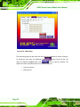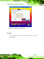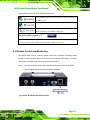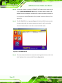
1
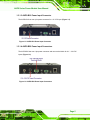
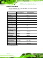
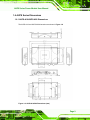
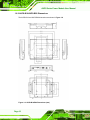
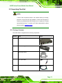
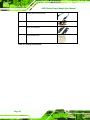
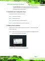
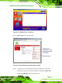
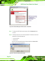
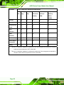
AUPS Series Power Module User Manual AUPS Series Power Module MODEL: AUPS Series VESA Mount Intelligent UPS Module 12 V DC Input or 9 V ~ 36 V DC Input Network Remote Management Support User Manual Page i Rev. 1.00 November, 2008 AUPS Series Power Module User Manual Revision Date Version Changes 2008-11 1.00 Initial release Page ii AUPS Series Power Module User Manual Copyright COPYRIGHT NOTICE The information in this document is subject to change without prior notice in order to improve reliability, design and function and does not represent a commitment on the part of the manufacturer. In no event will the manufacturer be liable for direct, indirect, special, incidental, or consequential damages arising out of the use or inability to use the product or documentation, even if advised of the possibility of such damages. This document contains proprietary information protected by copyright. All rights are reserved. No part of this manual may be reproduced by any mechanical, electronic, or other means in any form without prior written permission of the manufacturer. TRADEMARKS All registered trademarks and product names mentioned herein are used for identification purposes only and may be trademarks and/or registered trademarks of their respective owners. Page iii AUPS Series Power Module User Manual Manual Conventions WARNING! Warnings appear where overlooked details may cause damage to the equipment or result in personal injury. Warnings should be taken seriously. Warnings are easy to recognize. The word “warning” is written as “WARNING,” both capitalized and bold and is followed by text. The text is the warning message. A warning message is shown below: WARNING: This is an example of a warning message. Failure to adhere to warning messages may result in permanent damage to the AUPS Series or personal injury to the user. Please take warning messages seriously. CAUTION! Cautionary messages should also be heeded to help reduce the chance of losing data or damaging the AUPS Series. Cautions are easy to recognize. The word “caution” is written as “CAUTION,” both capitalized and bold and is followed. The text is the cautionary message. A caution message is shown below: CAUTION: This is an example of a caution message. Failure to adhere to cautions messages may result in permanent damage to the AUPS Series. Please take caution messages seriously. Page iv AUPS Series Power Module User Manual NOTE: These messages inform the reader of essential but non-critical information. These messages should be read carefully as any directions or instructions contained therein can help avoid making mistakes. Notes are easy to recognize. The word “note” is written as “NOTE,” both capitalized and bold and is followed by text. The text is the cautionary message. A note message is shown below: NOTE: This is an example of a note message. Notes should always be read. Notes contain critical information about the AUPS Series. Please take note messages seriously. Page v AUPS Series Power Module User Manual Packing List NOTE: If any of the components listed in the checklist below are missing, please do not proceed with the installation. Contact the IEI reseller or vendor you purchased the AUPS Series from or contact an IEI sales representative directly. To contact an IEI sales representative, please send an email to [email protected]. The items listed below should all be included in the AUPS Series package. 1 x AUPS Series UPS module 1 x Li-ion battery pack 1 x DC output cable 1 x USB cable 1 x DC output switch cable 1 x Screw kit 1 x Mounting bracket 2 x Wall mount brackets 1 x Utility software CD Images of the above items are shown in Chapter 3. Page vi AUPS Series Power Module User Manual Table of Contents 1 INTRODUCTION.......................................................................................................... 1 1.1 AUPS SERIES OVERVIEW ........................................................................................... 2 1.2 AUPS SERIES UPS MODULE FEATURES ..................................................................... 2 1.3 EXTERNAL OVERVIEW ................................................................................................ 3 1.3.1 I/O interface panel (Standard) ........................................................................... 3 1.3.1.1 AUPS-A10 Power Input Connector ............................................................ 4 1.3.1.2 AUPS-A20 Power Input Connectors .......................................................... 4 1.3.1.3 AUPS-B10 Power Input Connector ............................................................ 5 1.3.1.4 AUPS-B20 Power Input Connectors........................................................... 5 1.3.2 LED Indicators................................................................................................... 6 1.4 AUPS SERIES SPECIFICATIONS ................................................................................... 7 1.5 BATTERY SPECIFICATIONS .......................................................................................... 8 1.6 AUPS SERIES DIMENSIONS ........................................................................................ 9 1.6.1 AUPS-A10/AUPS-A20 Dimensions.................................................................... 9 1.6.2 AUPS-B10/AUPS-B20 Dimensions.................................................................. 10 2 UNPACKING ................................................................................................................11 2.1 ANTI-STATIC PRECAUTIONS ...................................................................................... 12 2.2 UNPACKING .............................................................................................................. 12 2.2.1 Unpacking Precautions.................................................................................... 12 2.3 UNPACKING CHECKLIST ........................................................................................... 13 2.3.1 Package Contents............................................................................................. 13 3 INSTALLATION ......................................................................................................... 15 3.1 ANTI-STATIC PRECAUTIONS ...................................................................................... 16 3.2 INSTALLATION PRECAUTIONS ................................................................................... 16 3.3 INSTALLATION AND CONFIGURATION STEPS ............................................................. 17 3.4 BATTERY PACK INSTALLATION ................................................................................. 17 3.5 MOUNTING THE AUPS SERIES ................................................................................. 18 3.6 CONNECTING THE AUPS SERIES .............................................................................. 20 4 SOFTWARE APPLICATION..................................................................................... 21 Page vii AUPS Series Power Module User Manual 4.1 INTRODUCTION......................................................................................................... 22 4.2 MONITORING DC POWER AND SMART BATTERY ...................................................... 22 4.2.1 Application Installation.................................................................................... 22 4.2.2 Status Information............................................................................................ 25 4.2.2.1 DC Detection ............................................................................................ 25 4.2.2.2 Battery Detection ...................................................................................... 26 4.2.2.3 Total Battery Time .................................................................................... 26 4.2.3 Battery Information.......................................................................................... 27 4.2.4 LAN Setting ...................................................................................................... 27 4.2.5 Setting .............................................................................................................. 29 4.3 REMOTE CONTROL AND MONITORING ...................................................................... 31 A HAZARDOUS MATERIALS DISCLOSURE ......................................................... 36 A.1 HAZARDOUS MATERIALS DISCLOSURE TABLE FOR IPB PRODUCTS CERTIFIED AS ROHS COMPLIANT UNDER 2002/95/EC WITHOUT MERCURY ....................................... 37 Page viii AUPS Series Power Module User Manual List of Figures Figure 1-1: AUPS Series UPS Module ..........................................................................................2 Figure 1-2: AUPS Series Standard I/O Interface Connectors.....................................................3 Figure 1-3: AUPS-A10 Power Input Connector............................................................................4 Figure 1-4: AUPS-A20 Power Input Connectors..........................................................................4 Figure 1-5: AUPS-B10 Power Input Connector............................................................................5 Figure 1-6: AUPS-B20 Power Input Connectors..........................................................................5 Figure 1-7: AUPS Series LED Indicators......................................................................................6 Figure 1-8: AUPS-A10/A20 Dimensions (mm) .............................................................................9 Figure 1-9: AUPS-B10/B20 Dimensions (mm) ...........................................................................10 Figure 3-1: Top Cover Retention Screws (Rear Panel) .............................................................17 Figure 3-2: Top Cover Retention Screws (Top Panel) ..............................................................18 Figure 3-3: Battery Pack Installation ..........................................................................................18 Figure 3-4: Mounting Bracket Installation..................................................................................19 Figure 3-5: Mounting the AUPS Series.......................................................................................19 Figure 3-6: AUPS Series and Panel PC Connection .................................................................20 Figure 4-1: Welcome Screen .......................................................................................................22 Figure 4-2: Select Installation Folder..........................................................................................23 Figure 4-3: Ready to Install the Program ...................................................................................23 Figure 4-4: Installing AUPS .........................................................................................................24 Figure 4-5: Installation Complete................................................................................................24 Figure 4-6: AUPS Battery Status Monitor Application..............................................................24 Figure 4-7: Status Information ....................................................................................................25 Figure 4-8: DC Detection..............................................................................................................25 Figure 4-9: Battery Detection ......................................................................................................26 Figure 4-10: Total Battery Time...................................................................................................27 Figure 4-11: Battery Information .................................................................................................27 Figure 4-12: LAN Setting..............................................................................................................28 Figure 4-13: LAN Setting – Change Password ..........................................................................29 Figure 4-14: Application Setting .................................................................................................30 Figure 4-15: COM Port Status......................................................................................................30 Page ix AUPS Series Power Module User Manual Figure 4-16: RJ-45 Remote LAN Connector...............................................................................31 Figure 4-17: IEI REMOTE AP .......................................................................................................32 Figure 4-18: IEI REMOTE AP – IP Address ................................................................................33 Figure 4-19: Remote Management Web Interface - Status .......................................................33 Figure 4-20: Remote Management Web Interface - Send Email ..............................................34 Figure 4-21: Enter User Name and Password............................................................................34 Figure 4-22: Board Configuration ...............................................................................................35 Page x AUPS Series Power Module User Manual List of Tables Table 1-1: LED Indicators ..............................................................................................................6 Table 1-2: AUPS Series Specifications.........................................................................................7 Table 1-3: Battery Specifications ..................................................................................................8 Table 3-1: Package List Contents ...............................................................................................14 Page xi AUPS Series Power Module User Manual Chapter 1 1 Introduction Page 1 AUPS Series Power Module User Manual 1.1 AUPS Series Overview Figure 1-1: AUPS Series UPS Module The highly efficient, high-performance AUPS Series UPS (Uninterruptible Power Supply) module installed with a Li-ion battery to provide stable 12V output and uninterruptible power to the IEI AFOLUX series panel PCs. The UPS module also receives either 12 V input or a wide range of inputs between 6 V and 36 V DC. The AUPS Series is built on an intelligent design and provides outstanding line and load regulations. The AUPS Series is capable of providing power for certain of time in power failure. The AUPS Series UPS module comes with the utility software that provides information on current power source and battery status. With the AUPS software installed and network connected, the AUPS Series can be monitored and turned on/off through a remote computer. 1.2 AUPS Series UPS Module Features Rugged metal enclosure for standard VESA 75/100 mounting Wide range power input (9 ~ 36 V) by DC jack or terminal block Network management through web-based interface in remote computer. No additional administration software installation is required. Page 2 Supports PC-based utility for monitoring power and battery status Auto shut down when battery low Provides stable power to AFOLUX PPC during line sags and spikes. Absorb power surges and transients AUPS Series Power Module User Manual 1.3 External Overview 1.3.1 I/O interface panel (Standard) The I/O interface panel of the AUPS Series (see Figure 1-2) has the following standard I/O interface connectors: 1 x 12 V DC output jack 1 x USB mini-B connector 1 x Network remote management port (RJ-45) 1 x DC output switch terminal block 1 x DC on/off button The standard external I/O interface connector panel is shown in Figure 1-2. Figure 1-2: AUPS Series Standard I/O Interface Connectors Page 3 AUPS Series Power Module User Manual 1.3.1.1 AUPS-A10 Power Input Connector The AUPS-A10 has one power jack for +12 V DC input (Figure 1-3). Figure 1-3: AUPS-A10 Power Input Connector 1.3.1.2 AUPS-A20 Power Input Connectors The AUPS-A20 has one power jack and one terminal block for 9 V ~ 36 V DC inputs (Figure 1-4). Figure 1-4: AUPS-A20 Power Input Connectors Page 4 AUPS Series Power Module User Manual 1.3.1.3 AUPS-B10 Power Input Connector The AUPS-B10 has one 4-pin power connector for +12 V DC input (Figure 1-5). Figure 1-5: AUPS-B10 Power Input Connector 1.3.1.4 AUPS-B20 Power Input Connectors The AUPS-B20 has one 4-pin power connector and one terminal block for 9 V ~ 36 V DC inputs (Figure 1-6). Figure 1-6: AUPS-B20 Power Input Connectors Page 5 AUPS Series Power Module User Manual 1.3.2 LED Indicators The side panel of the AUPS Series has three LED indicators to indicate the power and battery status (Figure 1-7). Figure 1-7: AUPS Series LED Indicators All the LED statuses are listed in Table 1-1. Power Input LED Charger Status LED Battery Status LED Color Green Yellow Orange Off DC power out -- -- On DC power in Discharging (battery full) Battery discharging Charging Battery low Blinking -Table 1-1: LED Indicators Page 6 AUPS Series Power Module User Manual 1.4 AUPS Series Specifications The AUPS Series UPS module technical specifications are listed in Table 1-2. Model Name AUPS-A10 AUPS-A20 VESA Type VESA 75 mm x 75 mm AUPS-B10 AUPS-B20 VESA 75 mm x 75 mm VESA 100 mm x 100 mm Output Voltage +12 V +/-5% +12 V +/-5% +12 V +/-5% Power 60 W 60 W 100 W Input Voltage +12 V +9 V ~ +36 V +12 V +9 V ~ +36 V Battery Type Li-ion 2S2P Li-ion 2S2P Li-ion 4S2P Li-ion 4S2P Normal 7.4 V 7.4 V 14.8 V 14.8 V Voltage 3800 mAH 3800 mAH 3800 mAH 3800 mAH Backup 60 W / 10 Min 60 W / 10 Min 100 W / 10 Min 100 W / 10 Min Dimensions 150 x 95 x 34 (mm) 150 x 95 x 34 (mm) 170 x 150 x 34 170 x 150 x 34 Physical (LxWxH) LED +12 V +/-5% 100 W (mm) (mm) Weight 1.2 kg 1.2 kg 1.8 kg 1.8 kg Green DC power input DC power input DC power input DC power input Yellow Battery charging Battery charging Battery charging Battery charging Orange Battery discharging Battery discharging Battery discharging Battery discharging Temperature Operating Storage 0°C ~ 40°C 0°C ~ 40°C 0°C ~ 40°C 0°C ~ 40°C -20°C ~ 50°C -20°C ~ 50°C -20°C ~ 50°C -20°C ~ 50°C Table 1-2: AUPS Series Specifications Page 7 AUPS Series Power Module User Manual 1.5 Battery Specifications The AUPS Series comes with a Li-ion smart battery. Some of the Li-ion battery specifications are listed in Table 1-3. AUPS-A10/AUPS-A20 AUPS-B10/AUPS-B20 Battery Model BAT-LI-2S2P3800 BAT-LI-4S2P3800 Battery Type Li-ion Li-ion Nominal Capacity 3800 mAH 3800 mAH Nominal Voltage 7.4 V 14.8 V Max. Charge Voltage 8.4 V 16.8 V Cut Off Voltage 5.6 V 11.2 V 2A 2A 7.6 A 7.6 A 250 mA/min 200 mA/min Discharge Protection UVP/OCP UVP/OCP Charge Protection OVP/OCP OVP/OCP Self-discharge Rate 340 uA ~ 440 uA 340 uA ~ 440 uA Dimensions 139 mm x 47 mm x 26 mm 165 mm x 76 mm x 26 mm Ambient Temperature 0°C ~ +40°C 0°C ~ +40°C Storage Temperature -20°C ~ +60°C -20°C ~ +60°C Backup 60 W/10 min 100 W/ 10 min Suggested Charge Current (Max.) System Continuous Discharging Current (Max.) The End of Charge Condition Table 1-3: Battery Specifications Page 8 AUPS Series Power Module User Manual 1.6 AUPS Series Dimensions 1.6.1 AUPS-A10/AUPS-A20 Dimensions The AUPS-A10 and AUPS-A20 dimensions are shown in Figure 1-8. Figure 1-8: AUPS-A10/A20 Dimensions (mm) Page 9 AUPS Series Power Module User Manual 1.6.2 AUPS-B10/AUPS-B20 Dimensions The AUPS-B10 and AUPS-B20 dimensions are shown in Figure 1-8. Figure 1-9: AUPS-B10/B20 Dimensions (mm) Page 10 AUPS Series Power Module User Manual Chapter 2 2 Unpacking Page 11 AUPS Series Power Module User Manual 2.1 Anti-static Precautions WARNING: Failure to take ESD precautions during the installation of the AUPS Series may result in permanent damage to the AUPS Series and severe injury to the user. Electrostatic discharge (ESD) can cause serious damage to electronic components, including the AUPS Series. Dry climates are especially susceptible to ESD. It is therefore critical that whenever the AUPS Series, or any other electrical component is handled, the following anti-static precautions are strictly adhered to. Wear an anti-static wristband: Wearing a simple anti-static wristband can help to prevent ESD from damaging the board. Self-grounding: Before handling the board touch any grounded conducting material. During the time the board is handled, frequently touch any conducting materials that are connected to the ground. Use an anti-static pad: When configuring the AUPS Series, place it on an antic-static pad. This reduces the possibility of ESD damaging the AUPS Series. Only handle the edges of the PCB: When handling the PCB, hold the PCB by the edges. 2.2 Unpacking 2.2.1 Unpacking Precautions When the AUPS Series is unpacked, please do the following: Follow the anti-static precautions outlined in Section 2.1. Make sure the packing box is facing upwards so the AUPS Series does not fall out of the box. Page 12 Make sure all the components shown in Section 2.3 are present. AUPS Series Power Module User Manual 2.3 Unpacking Checklist NOTE: If some of the components listed in the checklist below are missing, please do not proceed with the installation. Contact the IEI reseller or vendor you purchased the AUPS Series from or contact an IEI sales representative directly. To contact an IEI sales representative, please send an email to [email protected]. 2.3.1 Package Contents The AUPS Series is shipped with the following components: Quantity Item 1 AUPS Series UPS module 1 Li-ion battery pack 1 Mounting bracket 1 DC output cable 1 DC output switch cable Image Page 13 AUPS Series Power Module User Manual 1 USB Type A to mini-B cable 1 Screw kit 2 Wall mount bracket 1 Utility software CD Table 2-1: Package List Contents Page 14 AUPS Series Power Module User Manual Chapter 3 3 Installation Page 15 AUPS Series Power Module User Manual 3.1 Anti-static Precautions WARNING: Failure to take ESD precautions during the maintenance of the AUPS Series may result in permanent damage to the AUPS Series and severe injury to the user. Electrostatic discharge (ESD) can cause serious damage to electronic components, including the AUPS Series. Dry climates are especially susceptible to ESD. It is therefore critical that whenever the AUPS Series is accessed internally, or any other electrical component is handled, the following anti-static precautions are strictly adhered to. Wear an anti-static wristband: - Wearing a simple anti-static wristband can help to prevent ESD from damaging the board. Self-grounding: - Before handling the board touch any grounded conducting material. During the time the board is handled, frequently touch any conducting materials that are connected to the ground. Use an anti-static pad: - When configuring the AUPS Series, place it on an antic-static pad. This reduces the possibility of ESD damaging the AUPS Series. Only handle the edges of the PCB: - When handling the PCB, hold the PCB by the edges. 3.2 Installation Precautions When installing the power module, please follow the precautions listed below: Power turned off: When installing the power module, make sure the power is off. Failing to turn off the power may cause severe injury to the body and/or damage to the system. Certified Engineers: Only certified engineers should install and modify onboard functionalities. Page 16 AUPS Series Power Module User Manual Anti-static Discharge: If a user open the top cover of the power module, to configure the jumpers or plug in added peripheral devices, ground themselves first and wear and anti-static wristband. 3.3 Installation and Configuration Steps The following installation steps must be followed. Step 1: Unpack the UPS module Step 2: Install the battery pack Step 3: Mount UPS module to the AFOLUX panel PC Step 4: Connect the UPS module to the AFOLUX panel PC Step 0: 3.4 Battery Pack Installation The battery pack must be installed to enable the UPS module. To install the battery pack, follow the steps below. Step 1: Remove the four top cover retention screws (Figure 3-1 and Figure 3-2) and lift the top cover off the AUPS Series module. Figure 3-1: Top Cover Retention Screws (Rear Panel) Page 17 AUPS Series Power Module User Manual Figure 3-2: Top Cover Retention Screws (Top Panel) Step 2: Install the battery pack into the AUPS Series. Make sure the battery pack is connected to the battery connector on the board. (Figure 3-3) Figure 3-3: Battery Pack Installation Step 3: Secure the battery pack with two retention screws. Step 4: Replace the top cover. Step 0: 3.5 Mounting the AUPS Series To mount the AUPS Series onto the rear panel of the AFOLUX panel PC, follow the steps below. Step 1: Install the mounting bracket onto the rear panel of the AFL panel PC. Align the screw holes in the mounting bracket with the VESA screw holes in the rear of Page 18 AUPS Series Power Module User Manual the panel PC. Secure the mounting bracket to the panel PC with four retention screws (Figure 3-4). Figure 3-4: Mounting Bracket Installation Step 2: Place the AUPS Series onto the mounting bracket. Secure the AUPS Series to the bracket with three retention screws, one on the top panel and one on each side panel (Figure 3-5). Step 0: Figure 3-5: Mounting the AUPS Series Page 19 AUPS Series Power Module User Manual 3.6 Connecting the AUPS Series To support the UPS function to the panel PC, the AUPS Series must be connected to the power source and to the panel PC. Figure 3-6 shows the connections. Figure 3-6: AUPS Series and Panel PC Connection Page 20 AUPS Series Power Module User Manual Chapter 4 4 Software Application Page 21 AUPS Series Power Module User Manual 4.1 Introduction The IEI AUPS Battery Status Monitor application detects the information of the smart battery and monitors the battery status. It is recommended to execute this AUPS application in Windows XP SP2 environment. 4.2 Monitoring DC Power and Smart Battery 4.2.1 Application Installation Follow the steps below to install the AUPS Battery Status Monitor application. Step 1: Insert the driver CD into the system. Open the x:\AUPS_Setup\ AUPS_SetupV1.4 directory. Double click the Setup.exe icon. Step 2: A welcome screen appears (Figure 4-1). To continue the installation process click NEXT. Figure 4-1: Welcome Screen Step 3: The Select Installation Folder window appears (Figure 4-2). Select a folder to install the application. Page 22 AUPS Series Power Module User Manual Figure 4-2: Select Installation Folder Step 4: Click NEXT and the Installshield Wizard is ready to install the program (Figure 4-3). Figure 4-3: Ready to Install the Program Step 5: Click NEXT to continue. The Installing AUPS_Setup screen appears as the program is installed (Figure 4-4). Page 23 AUPS Series Power Module User Manual Figure 4-4: Installing AUPS Step 6: The Installation Complete window appears (Figure 4-5). Click Close to exit. Figure 4-5: Installation Complete Step 7: To launch the application, double click the shortcut (Figure 4-6) on the desktop. Step 0: Figure 4-6: AUPS Battery Status Monitor Application Page 24 AUPS Series Power Module User Manual 4.2.2 Status Information The IEI AUPS Battery Status Monitor application shows the DC power status and battery status (Figure 4-7). The following sections describe the status information in details. Figure 4-7: Status Information 4.2.2.1 DC Detection When the DC power is connected to the AUPS series power module, the AUPS Battery Status Monitor detects it and shows in the screen as Figure 4-8. Figure 4-8: DC Detection Page 25 AUPS Series Power Module User Manual 4.2.2.2 Battery Detection When the smart battery is connected to the AUPS series power module, the AUPS Battery Status Monitor detects it and shows in the screen as Figure 4-9. Two batteries can be connected to the AUPS series power module at the same time. The second battery information is shown in the Battery A Detection section if connected. Figure 4-9: Battery Detection The battery is connected to the AUPS series. Off The battery is not connected to the AUPS series. Full The battery is fully charged. Low The battery is low. Using The battery is being used. Charging The battery is being charged. Standby The battery is fully charged and ready to be used anytime. >60 C The battery temperature is above 60°C. <60 C The battery temperature is below 60°C. 4.2.2.3 Total Battery Time The total battery time is shown in the top right corner (Figure 4-10) of the status screen to indicate the total battery remaining time. Page 26 AUPS Series Power Module User Manual Figure 4-10: Total Battery Time 4.2.3 Battery Information Click on the BAT. A tab to view the information of battery. The listed information includes battery type, capacity, output voltage, temperature, charging rate, discharging rate and battery status (Figure 4-11). The values listed are updated per second. Figure 4-11: Battery Information 4.2.4 LAN Setting The LAN Setting page is where to configure the Remote LAN settings for power on/off remote control and battery monitoring. To save the modified parameters of this page, click the button. To load the default settings, click button. Page 27 AUPS Series Power Module User Manual Figure 4-12: LAN Setting The LAN Setting page can also setup the user name and password for remote monitoring. To change the user name and password, click button. Enter the new user name and password (Figure 4-13). Click button to save the settings. The default user name and password for the LAN setting page are: Page 28 User name: admin Password: IEI AUPS Series Power Module User Manual Figure 4-13: LAN Setting – Change Password 4.2.5 Setting Click on the SETTING tab to select the COM port, enable/disable buzzer, LAN and DC output (Figure 4-14). Page 29 AUPS Series Power Module User Manual Figure 4-14: Application Setting When the AUPS Battery Status Monitor application starts up, it automatically scans all COM port (COM1~COM16) and shows the valid COM port. Figure 4-15 shows the AUPS application is communicating with AUPS Series through COM 6. To change the serial port to communicate, select a proper port number from the list and click Connect. Before changing, please make sure the selected serial port is not used by other devices. Figure 4-15: COM Port Status Page 30 AUPS Series Power Module User Manual Other functions can be set in the SETTING tab include Check to disable the buzzer that warns when the system is switching to use battery power. Check to enable the LAN for remote monitoring function. Check to enable the remote computer to turn the system power on or off. (This function is not available at this stage.) Set the battery capacity parameter for the system to shut down automatically. In this case, the system will shut down automatically when the battery capacity is below 5%. 4.3 Remote Control and Monitoring The AUPS Series can be controlled (power on/off) and monitored the battery status through a remote computer located in the same subnet with the AUPS Series. To control and monitor the AUPS Series remotely, follow the steps below. Step 1: Connect the RJ-45 remote LAN connector on the bottom panel of the AUPS Series (Figure 4-16) to a local area network connector. Figure 4-16: RJ-45 Remote LAN Connector Page 31 AUPS Series Power Module User Manual Step 2: In a remote computer, install the IEI REMOTE AP. Double click the setup.exe file in the x:\Other\AUPS REMOTE AP directory. Follow the steps to install the IEI REMOTE AP. After installation, launch the AP. If there is a problem to launch the tool, execute the dotnetfxRedist20.exe first (located in the same directory of the driver CD). Step 3: The IEI REMOTE AP tool appears (Figure 4-17). All the AUPS Series module in the same subnet with this remote computer are shown in the list on the right. Click the function buttons on the left to control the AUPS Series. Figure 4-17: IEI REMOTE AP Step 4: To access the web interface for advanced monitoring and functions, double click the IP address of the connected AUPS Series (Figure 4-18). Page 32 AUPS Series Power Module User Manual Figure 4-18: IEI REMOTE AP – IP Address Step 5: Figure 4-19 shows in a web browser. Figure 4-19: Remote Management Web Interface - Status Step 6: To send an email to an administrator through the SMTP server, click Send E-mail button on the left. Fill out the information as indicated in Figure 4-20. Click the Send Message button to send the email. Page 33 AUPS Series Power Module User Manual Figure 4-20: Remote Management Web Interface - Send Email Step 7: To configure the AUPS Series network setting, click the Configuration button on the left. Step 8: A window prompts for the user name and password. The default user name and password for the LAN setting page are: User name: admin Password: IEI If the user name and password has been change as described in Section 4.2.4, enter the new user name and password. Figure 4-21: Enter User Name and Password Page 34 AUPS Series Power Module User Manual Step 9: The Board Configuration window appears. Configure the network settings and click the Save Config button. Incorrect settings may cause the board to lose network connectivity. Recovery options are provided on the next page. Step 0: Figure 4-22: Board Configuration Page 35 AUPS Series Power Module User Manual Appendix A A Hazardous Materials Disclosure Page 36 AUPS Series Power Module User Manual A.1 Hazardous Materials Disclosure Table for IPB Products Certified as RoHS Compliant Under 2002/95/EC Without Mercury The details provided in this appendix are to ensure that the product is compliant with the Peoples Republic of China (China) RoHS standards. The table below acknowledges the presences of small quantities of certain materials in the product, and is applicable to China RoHS only. A label will be placed on each product to indicate the estimated “Environmentally Friendly Use Period” (EFUP). This is an estimate of the number of years that these substances would “not leak out or undergo abrupt change.” This product may contain replaceable sub-assemblies/components which have a shorter EFUP such as batteries and lamps. These components will be separately marked. Please refer to the table on the next page. Page 37 AUPS Series Power Module User Manual Part Name Toxic or Hazardous Substances and Elements Lead Mercury Cadmium Hexavalent Polybrominated Polybrominated (Pb) (Hg) (Cd) Chromium Biphenyls Diphenyl (CR(VI)) (PBB) Ethers (PBDE) Housing X O O O O X Display X O O O O X Printed Circuit X O O O O X X O O O O O X O O O O X Fan Assembly X O O O O X Power Supply X O O O O X O O O O O O Board Metal Fasteners Cable Assembly Assemblies Battery O: This toxic or hazardous substance is contained in all of the homogeneous materials for the part is below the limit requirement in SJ/T11363-2006 X: This toxic or hazardous substance is contained in at least one of the homogeneous materials for this part is above the limit requirement in SJ/T11363-2006 Page 38 AUPS Series Power Module User Manual 此附件旨在确保本产品符合中国 RoHS 标准。以下表格标示此产品中某有毒物质的含量符 合中国 RoHS 标准规定的限量要求。 本产品上会附有”环境友好使用期限”的标签,此期限是估算这些物质”不会有泄漏或突变”的 年限。本产品可能包含有较短的环境友好使用期限的可替换元件,像是电池或灯管,这些 元件将会单独标示出来。 部件名称 有毒有害物质或元素 铅 汞 镉 六价铬 多溴联苯 多溴二苯 (Pb) (Hg) (Cd) (CR(VI)) (PBB) 醚 (PBDE) 壳体 X O O O O X 显示 X O O O O X 印刷电路板 X O O O O X 金属螺帽 X O O O O O 电缆组装 X O O O O X 风扇组装 X O O O O X 电力供应组装 X O O O O X 电池 O O O O O O O: 表示该有毒有害物质在该部件所有物质材料中的含量均在 SJ/T11363-2006 标准规定的限量要求以下。 X: 表示该有毒有害物质至少在该部件的某一均质材料中的含量超出 SJ/T11363-006 标准规定的限量要求。 Page 39