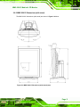
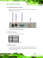
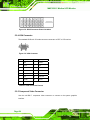
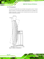
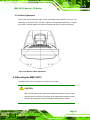
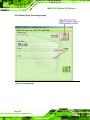
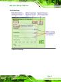
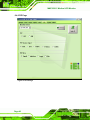
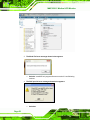
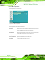
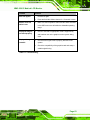
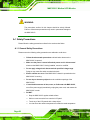
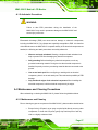
1
MMC-2201C Medical LCD Monitor Fub Page i MMC-2201C Medical LCD Monitor Revision History Date Version Changes 2008-04-08 1.00 Initial release Page ii MMC-2201C Medical LCD Monitor Copyright COPYRIGHT NOTICE The information in this document is subject to change without prior notice in order to improve reliability, design and function and does not represent a commitment on the part of the manufacturer. In no event will the manufacturer be liable for direct, indirect, special, incidental, or consequential damages arising out of the use or inability to use the product or documentation, even if advised of the possibility of such damages. This document contains proprietary information protected by copyright. All rights are reserved. No part of this manual may be reproduced by any mechanical, electronic, or other means in any form without prior written permission of the manufacturer. TRADEMARKS All registered trademarks and product names mentioned herein are used for identification purposes only and may be trademarks and/or registered trademarks of their respective owners. Page iii MMC-2201C Medical LCD Monitor Manual Conventions WARNING! Warnings appear where overlooked details may cause damage to the equipment or result in personal injury. Warnings should be taken seriously. Warnings are easy to recognize. The word “warning” is written as “WARNING,” both capitalized and bold and is followed by text. The text is the warning message. A warning message is shown below: WARNING: This is an example of a warning message. Failure to adhere to warning messages may result in permanent damage to the MMC-2201C or personal injury to the user. Please take warning messages seriously. CAUTION! Cautionary messages should also be heeded to help reduce the chance of losing data or damaging the MMC-2201C. Cautions are easy to recognize. The word “caution” is written as “CAUTION,” both capitalized and bold and is followed. The italicized text is the cautionary message. A caution message is shown below: CAUTION: Page iv MMC-2201C Medical LCD Monitor This is an example of a caution message. Failure to adhere to cautions messages may result in permanent damage to the MMC-2201C. Please take caution messages seriously. NOTE: These messages inform the reader of essential but non-critical information. These messages should be read carefully as any directions or instructions contained therein can help avoid making mistakes. Notes are easy to recognize. The word “note” is written as “NOTE,” both capitalized and bold and is followed by text. The text is the cautionary message. A note message is shown below: NOTE: This is an example of a note message. Notes should always be read. Notes contain critical information about the MMC-2201C. Please take note messages seriously. Page v MMC-2201C Medical LCD Monitor Packing List NOTE: If any of the components listed in the checklist below are missing, please do not proceed with the installation. Contact the IEI reseller or vendor you purchased the MMC-2201C from or contact an IEI sales representative directly. To contact an IEI sales representative, please send an email to [email protected]. PACKING LIST All the monitors in the MMC-2201C are shipped with the following components: 1 x MMC-2201C Medical LCD monitor 1 x Monitor stand 1 x Power Adapter 2 x Power Cords (1 x US, 1 x EU) 1 x DVI-D Signal Cable 1 x Utility CD-ROM 1 x VGA cable 1 x HW OSD Key for setup If any of these items are missing or damaged, contact the distributor or sales representative immediately. Images of the above items are shown in Section 4.1.3 Page vi MMC-2201C Medical LCD Monitor Table of Contents 1 INTRODUCTION..................................................................................................... 1 1.1 MMC-2201C MEDICAL LCD MONITOR OVERVIEW ................................................. 2 1.2 FEATURES .................................................................................................................. 2 2 MECHANICAL OVERVIEW ................................................................................. 5 2.1 INTRODUCTION .......................................................................................................... 6 2.2 FRONT PANEL ............................................................................................................. 6 2.3 BOTTOM PANEL.......................................................................................................... 7 2.4 REAR PANEL .............................................................................................................. 8 2.5 EXTERNAL PERIPHERAL INTERFACE CONNECTOR (EPIC) PANEL ............................... 8 2.6 PHYSICAL DIMENSIONS .............................................................................................. 9 2.6.1 MMC-2201C Dimensions (without stand) ......................................................... 9 2.6.2 MMC-2201C Dimensions (with stand) .............................................................11 3 SPECIFICATIONS................................................................................................. 13 3.1 GENERAL SPECIFICATIONS ....................................................................................... 14 3.1.1 Color Monitors................................................................................................. 14 3.1.2 Classification ................................................................................................... 15 4 UNPACKING .......................................................................................................... 17 4.1 UNPACKING.............................................................................................................. 18 4.1.1 Packaging ........................................................................................................ 18 4.1.2 Unpacking Procedure ...................................................................................... 18 4.1.3 Packing List ..................................................................................................... 19 5 INSTALLATION .................................................................................................... 21 5.1 INSTALLATION PRECAUTIONS ................................................................................... 22 5.2 EXTERNAL PERIPHERAL INTERFACE CONNECTORS .................................................. 22 5.2.1 EPIC Panel Connectors Overview................................................................... 23 5.2.2 DC 12V Connector........................................................................................... 23 5.2.3 DVI-D Connector............................................................................................. 23 5.2.4 VGA Connector ................................................................................................ 24 Page vii MMC-2201C Medical LCD Monitor 5.2.5 Component Video Connector ........................................................................... 24 5.3 DISPLAY ADJUSTMENT ............................................................................................. 25 5.3.1 Height Adjustment............................................................................................ 26 5.3.2 Portrait/Landscape Orientation....................................................................... 27 5.3.3 Tilt Adjustment ................................................................................................. 28 5.3.4 Swivel Adjustment ............................................................................................ 29 5.4 MOUNTING THE MMC-2201C ................................................................................. 29 5.4.1 Monitor Arm or Stand Installation................................................................... 30 6 ON-SCREEN-DISPLAY (OSD) CONTROLS ..................................................... 31 6.1 IEI SMARTOSD QUICK INSTALLATION GUIDE ......................................................... 32 6.2 PRE-INSTALLATION NOTICE...................................................................................... 32 6.3 SMARTOSD INSTALL ................................................................................................ 32 6.4 SMARTOSD MENU STRUCTURE ............................................................................... 39 6.4.1 Manage Page ................................................................................................... 41 6.4.2 EDID Page....................................................................................................... 42 6.4.3 Image Page ...................................................................................................... 43 6.4.4 Display Page (for analog signal)..................................................................... 44 6.4.5 Color Page ....................................................................................................... 45 6.4.6 PIP Page .......................................................................................................... 46 6.4.7 System Page ..................................................................................................... 47 6.4.8 About Page....................................................................................................... 48 6.5 SMARTOSD FAQ ..................................................................................................... 49 7 OSD KEYPAD......................................................................................................... 53 7.1 USER MODE OSD STRUCTURE ................................................................................ 54 7.1.1 OSD Buttons..................................................................................................... 54 7.1.2 OSD Menu Structure ........................................................................................ 55 7.2 USING THE OSD....................................................................................................... 56 7.2.1 Image Menu ..................................................................................................... 56 7.2.2 Display Menu ................................................................................................... 57 7.2.3 PiP Menu.......................................................................................................... 58 7.2.4 System Menu .................................................................................................... 59 7.2.4.1 OSD Configuration ................................................................................... 60 8 TROUBLESHOOTING ......................................................................................... 61 Page viii MMC-2201C Medical LCD Monitor 8.1 TROUBLESHOOTING ................................................................................................. 62 A SAFETY PRECAUTIONS..................................................................................... 65 A.1 SAFETY PRECAUTIONS ............................................................................................ 66 A.1.1 General Safety Precautions ............................................................................. 66 A.1.2 Anti-static Precautions .................................................................................... 67 A.2 MAINTENANCE AND CLEANING PRECAUTIONS ........................................................ 67 A.2.1 Maintenance and Cleaning.............................................................................. 67 A.2.2 Cleaning Tools ................................................................................................. 68 B GLOSSARY............................................................................................................. 69 C HAZARDOUS MATERIALS DISCLOSURE ..................................................... 73 C.1 HAZARDOUS MATERIAL DISCLOSURE TABLE FOR IPB PRODUCTS CERTIFIED AS ROHS COMPLIANT UNDER 2002/95/EC WITHOUT MERCURY ....................................... 74 INDEX.............................................................................................................................. 78 Page ix MMC-2201C Medical LCD Monitor List of Figures Figure 1-1: MMC-2201C Medical Monitor.............................................................................2 Figure 2-1: MMC-2201C Front Panel ....................................................................................6 Figure 2-2: MMC-2201C Bottom Panel.................................................................................7 Figure 2-3: MMC-2201C Rear Panel .....................................................................................8 Figure 2-4: MMC-2201C EPIC Panel .....................................................................................9 Figure 2-5: MMC-2201C Dimensions (without stand) (mm).............................................10 Figure 2-6: MMC-2201C Dimensions (with stand) (mm) ..................................................11 Figure 5-1: Monitor EPIC Panel Connectors .....................................................................23 Figure 5-2: DVI-D Connector Pinout Locations ................................................................24 Figure 5-3: VGA Connector.................................................................................................24 Figure 5-4: Component Video Connector Pinout Locations ...........................................25 Figure 5-5: Monitor Height Adjustment .............................................................................26 Figure 5-6: Monitor Portrait/Landscape Orientation ........................................................27 Figure 5-7: Monitor Tilt Adjustment ...................................................................................28 Figure 5-8: Monitor Swivel Adjustment .............................................................................29 Figure 5-9: VESA Mounting Holes......................................................................................30 Figure 6-1: smartOSD Installer ...........................................................................................33 Figure 6-2: smartOSD Welcome Screen ............................................................................34 Figure 6-3: smartOSD Folder Select Screen .....................................................................35 Figure 6-4: smartOSD Confirm Installation .......................................................................36 Figure 6-5: smartOSD Installation Progress .....................................................................37 Figure 6-6: smartOSD Installation Complete ....................................................................38 Figure 6-7: Manage Page.....................................................................................................41 Figure 6-8: EDID Page .........................................................................................................42 Figure 6-9: Image Page........................................................................................................43 Figure 6-10: Display Page ...................................................................................................44 Figure 6-11: Color Page.......................................................................................................45 Figure 6-12: PIP Page ..........................................................................................................46 Figure 6-13: System Page ...................................................................................................47 Figure 6-14: About Page......................................................................................................48 Figure 7-1: OSD Control Buttons .......................................................................................54 Page x MMC-2201C Medical LCD Monitor Figure 7-2: Image Menu.......................................................................................................56 Figure 7-3: Display Menu ....................................................................................................57 Figure 7-4: PiP Menu ...........................................................................................................58 Figure 7-5: System Menu ....................................................................................................59 Figure 7-6: OSD Configuration ...........................................................................................60 Page xi MMC-2201C Medical LCD Monitor List of Tables Table 2-1: Physical Dimensions ...........................................................................................9 Table 3-1: MMC-2201C Color Monitor Specifications.......................................................15 Table 4-1: Package List Contents ......................................................................................20 Table 5-1: DC 12V Connector Pinouts ...............................................................................23 Table 5-2: VGA Connector Pinouts ....................................................................................24 Table 5-3: Component Video Connector Pinouts .............................................................25 Table 7-1: Troubleshooting.................................................................................................63 Page xii MMC-2201C Medical LCD Monitor Chapter 1 1 Introduction Page 1 MMC-2201C Medical LCD Monitor 1.1 MMC-2201C Medical LCD Monitor Overview Figure 1-1: MMC-2201C Medical Monitor The MMC-2201C Medical LCD (MMC-2201C) monitor is a high performance, 2 Megapixel medical grade color LCD monitor designed for the exacting needs of diagnostic professionals that provides clear and sharp images with resolutions of up to 1600 x 1200 pixels, 300 cd/m2 brightness and 800:1 contrast ratio, making it ideal for diagnosing detailed medical graphics. The ergonomic design provides flexible four-way adjustments (lift, tilt, swivel and rotate) for ease of use and VESA mounting capabilities provide a wide array of mounting options. The MMC-2201C also uses a DVI digital interface, offering compatibility with the latest digital standards. 1.2 Features Some of the standard features of the MMC-2201C include: OSD control with automatic portrait/landscape orientation detection DVI-D digital interface Low resolution support Wide viewing angle Full screen availability Slim bezel Anti-glare and low-reflection glass Page 2 MMC-2201C Medical LCD Monitor Standard VESA mounting interface Ergonomically designed stand Various graphics card support: Matrox, RealVision, ATI, nVidia and other high-level commercial cards Page 3 MMC-2201C Medical LCD Monitor THIS PAGE IS INTENTIONALLY LEFT BLANK Page 4 MMC-2201C Medical LCD Monitor Chapter 2 2 Mechanical Overview Page 5 MMC-2201C Medical LCD Monitor 2.1 Introduction This chapter describes the general mechanical overview of the MMC-2201C monitors, including the front panel, external peripheral interface connector (EPIC) panel, available interfaces and overall dimensions. 2.2 Front Panel The front panel of the MMC-2201C has an LCD screen surrounded by a sturdy acrylonitrile butadiene styrene (ABS) and polycarbonate (PC) plastic frame. The front panel is shown in Figure 2-1. Figure 2-1: MMC-2201C Front Panel Page 6 MMC-2201C Medical LCD Monitor 2.3 Bottom Panel The bottom panel of the MMC-2201C has an OSD control panel and power on/off LED. The bottom panel also has a series of interface connectors. The bottom panel is shown in Figure 2-2. Figure 2-2: MMC-2201C Bottom Panel Page 7 MMC-2201C Medical LCD Monitor 2.4 Rear Panel The rear panel of the MMC-2201C has standard VESA mounting holes and the monitor’s external peripheral interface connector panel. The rear panel is shown in Figure 2-3. Figure 2-3: MMC-2201C Rear Panel 2.5 External Peripheral Interface Connector (EPIC) Panel All the models in the MMC-2201C have the same connector interfaces on the rear panel. The rear panel interface connectors are listed below and shown in Figure 2-4. 1 x Power connector 1 x DVI-D input connector 1 x VGA connector 1 x Component connector Page 8 MMC-2201C Medical LCD Monitor Figure 2-4: MMC-2201C EPIC Panel 2.6 Physical Dimensions The physical dimensions of the MMC-2201C monitors are specified in Table 2-1 below. Portrait Orientation Portrait Orientation Without Stand With Stand Width (mm) 380 380 Height (mm) 485 520 Depth (mm) 100 274 Table 2-1: Physical Dimensions 2.6.1 MMC-2201C Dimensions (without stand) The MMC-2201C dimensions (without stand) are shown in Figure 2-5 below. Page 9 MMC-2201C Medical LCD Monitor Figure 2-5: MMC-2201C Dimensions (without stand) (mm) Page 10 MMC-2201C Medical LCD Monitor 2.6.2 MMC-2201C Dimensions (with stand) The MMC-2201C dimensions (with stand) are shown in Figure 2-6 below. Figure 2-6: MMC-2201C Dimensions (with stand) (mm) Page 11 MMC-2201C Medical LCD Monitor THIS PAGE IS INTENTIONALLY LEFT BLANK Page 12 MMC-2201C Medical LCD Monitor Chapter 3 3 Specifications Page 13 MMC-2201C Medical LCD Monitor 3.1 General Specifications The following sections describe the MMC-2201C specifications. 3.1.1 Color Monitors Table 3-1 lists the specifications for the MMC-2201C. MMC-2201C Drive System Display area (H x V) (mm) Diagonal size of display Resolution (H x V) Display color Pixel pitch (H x V) (mm) Pixel format MMC-2201C a-Si TFT active matrix 398.4 x 298.8 51 cm (20.1 inches) 1600 x 1200 16,777,216 colors 0.255 x 0.255 RGB (Red dot, Green dot, Blue dot) vertical stripe Luminance-max. 300 (cd/m2) Contrast ratio 800:1 (typ.) Viewing angle Right 89o, Left 89o, Up 89o, Down 89o Response time (Ton + Toff) 16 ms (typ.) Polarizer surface/hardness Antiglare/2H Backlight Default gamma DICOM Calibration Preset Signal input OSD Power Adapter Input voltage range Power Adapter Input frequency range Power Adapter Max input AC current Power Adapter Power output Physical dimensions Page 14 6 CCFL Gamma 2.2 Yes Single link DVI-D (digital) Yes 100VAC-240VAC 47 Hz-63 Hz 1.25 A - 0.5 A 12 VDC, 8.33 A (max.), 100 W With stand: 520 x 380 x 274 (portrait) MMC-2201C Medical LCD Monitor MMC-2201C MMC-2201C (H x W x D) (mm) Without stand: 485 x 380 x 100 (portrait) Adjustable height range (with stand) Portrait: 520 mm ~ 590 mm Landscape: 465 mm ~ 535 mm Weight (without/with stand) Operating temperature Storage temperature Operation Relative Humidity Storage/Transportation Relative Humidity 7.5 kg/12.0 kg +10°C~+35°C 0°C~+45°C 30% ~75% Non-condensing 10% ~95% Non-condensing Table 3-1: MMC-2201C Color Monitor Specifications 3.1.2 Classification Power by Class I power adapter: No Applied Part. No protection against the ingress of water: IPX0 Mode of operation: Continuous Operation The equipment not suitable for use in the presence of a flammable anesthetic mixture with air or with oxygen or nitrous oxide: Not AP or APG Category: Page 15 MMC-2201C Medical LCD Monitor THIS PAGE IS INTENTIONALLY LEFT BLANK Page 16 MMC-2201C Medical LCD Monitor Chapter 4 4 Unpacking Page 17 MMC-2201C Medical LCD Monitor 4.1 Unpacking 4.1.1 Packaging When shipped, the MMC-2201C is packed inside two cardboard boxes, secured in place and protected by six polyethylene spacers. A smaller cardboard box containing all accessory items is also placed within the two cardboard boxes. 4.1.2 Unpacking Procedure CAUTION! Be sure the box containing the MMC-2201C is placed in an upright position before opening it in order to prevent any of the contents from being damaged. To unpack the MMC-2201C, follow the steps below: Step 1: Use box cutters, a knife or a sharp pair of scissors to open the seal on the top of the external box. Step 2: Open the internal box. Step 3: Remove the small cardboard box containing the accessory items. Step 4: Remove the right and left polyethylene spacers. Step 5: Remove the center polyethylene spacer from the rear of the panel. Step 6: Remove the front polyethylene spacer from in front of the panel. Step 7: Lift the MMC-2201C out of the boxes. Step 8: Remove any remaining polyethylene spacers from the panel. Page 18 MMC-2201C Medical LCD Monitor Step 9: Make sure all the components inside the box of accessories and listed in the packing list are present. Step 0: 4.1.3 Packing List NOTE: If some of the components listed in the checklist below are missing, please do not proceed with the installation. Contact the IEI reseller or vendor you purchased the MMC-2201C from or contact an IEI sales representative directly. To contact an IEI sales representative, please send an email to [email protected]. When the MMC-2201C is received, make sure all the components listed below are present. Page 19 MMC-2201C Medical LCD Monitor Quantity Item MMD Series LCD monitor 1 (with/without stand) 1 DVI cable 1 AC power adapter 1 AC power cable (US) 1 AC power cable (EU) 1 Utility CD 1 7-pin Mini-DIN to 3 BNC (P/N: 32000-113900-RS) 1 VGA to 5 BNC (P/N: 32000-114500-RS) Table 4-1: Package List Contents Page 20 Image MMC-2201C Medical LCD Monitor Chapter 5 5 Installation Page 21 MMC-2201C Medical LCD Monitor 5.1 Installation Precautions When installing the MMC-2201C, please follow the precautions listed below: Read the user manual: The user manual provides a complete description of the MMC-2201C, installation instructions and configuration options. DANGER! Disconnect Power: Power to the monitor must be disconnected when installing the MMC-2201C. Electric shock and personal injury might occur if the rear panel of the monitor is accessed while the power cord is still connected to an electrical outlet. Qualified Personnel: The MMC-2201C must be installed and operated only by trained and qualified personnel. Maintenance, upgrades, or repairs may only be carried out by qualified personnel who are familiar with the associated dangers. Mounting: The monitor is a heavy piece of equipment. Please ensure at least two people assist with mounting the monitor. Air Circulation: Make sure there is sufficient air circulation when installing the monitor. The monitor’s cooling vents must not be obstructed by any objects. Blocking the vents can cause overheating of the monitor. 5.2 External Peripheral Interface Connectors The external peripheral interface panel connectors for the MMC-2201C are listed below. 1 x Power connector 1 x DVI-D input connector 1 x VGA port 1 x Component connector Page 22 MMC-2201C Medical LCD Monitor 5.2.1 EPIC Panel Connectors Overview Figure 5-1 shows the EPIC panel connectors for the MMC-2201C. The following sections fully describe EPIC panel connectors. Figure 5-1: Monitor EPIC Panel Connectors 5.2.2 DC 12V Connector Use the DC 12V connector to power the monitor. PIN DESCRIPTION 1 GND 2 GND 3 +12V Table 5-1: DC 12V Connector Pinouts 5.2.3 DVI-D Connector The 24-pin female dual link digital only DVI (Digital Visual Interface) connector is a standard for high-speed, high-resolution digital displays. Use the DVI-D connector to connect the LCD to a system. Page 23 MMC-2201C Medical LCD Monitor Figure 5-2: DVI-D Connector Pinout Locations 5.2.4 VGA Connector The standard HD-D-sub 15 female connector connects to a CRT or LCD monitor. Figure 5-3: VGA Connector PIN Description PIN Description 1 RED 2 GREEN 3 BLUE 4 N/C 5 GND 6 GND 7 GND 8 GND 9 VCC 10 GND 11 N/C 12 DDC DAT 13 HSYNC 14 VSYNC 15 DDC CLK Table 5-2: VGA Connector Pinouts 5.2.5 Component Video Connector Use the mini-DIN 7 component video connector to connect to the system graphics interface. Page 24 MMC-2201C Medical LCD Monitor Figure 5-4: Component Video Connector Pinout Locations PIN DESCRIPTION PIN DESCRIPTION 1 VGND 5 VGND 2 Pb 6 Pr 3 VGND 7 VGND 4 Y Table 5-3: Component Video Connector Pinouts 5.3 Display Adjustment Every model in the MMC-2201C is assembled with an ergonomically designed stand. The monitor stand allows for adjustment of the display in multiple directions. The following sections fully describe the display adjustment parameters of the monitor stand. Page 25 MMC-2201C Medical LCD Monitor 5.3.1 Height Adjustment The height of the monitor can be adjusted whether in portrait or landscape position. To adjust the height, hold both sides of the monitor bezel and raise or lower the monitor to the desired height. The total range of movement in the vertical direction for the monitor is 70 mm. The minimum height of the monitor with stand is 276 mm and the maximum height of the monitor with stand is 346 mm. NOTE: For optimal viewing and preventing eye fatigue, keep the top of the monitor slightly lower than the viewer’s eye so that the line of sight when viewing the monitor is aimed downward. Figure 5-5: Monitor Height Adjustment Page 26 MMC-2201C Medical LCD Monitor 5.3.2 Portrait/Landscape Orientation The monitor can be oriented in either a portrait or landscape position. To adjust the portrait/landscape orientation, hold both sides of the monitor bezel and turn the monitor clockwise or counterclockwise as necessary. NOTE: To avoid scratching the bezel, raise the monitor to its highest position before rotating it. When the rotation is complete, the on screen display will automatically reorient itself to match the orientation of the monitor. Figure 5-6: Monitor Portrait/Landscape Orientation Page 27 MMC-2201C Medical LCD Monitor 5.3.3 Tilt Adjustment The monitor can be tilted to offer a more comfortable viewing position to the user. The total range of movement is 5° forward from a straight vertical position and 15° backward from a straight vertical position. To adjust the monitor, hold both sides of the monitor bezel and tilt forward or backward as necessary. Figure 5-7: Monitor Tilt Adjustment Page 28 MMC-2201C Medical LCD Monitor 5.3.4 Swivel Adjustment The monitor can be swiveled to offer a more comfortable viewing position to the user. The total range of movement is 90° (45° left or right from a straightforward position). To adjust the monitor, hold both sides of the monitor bezel and swivel left or right as necessary. Figure 5-8: Monitor Swivel Adjustment 5.4 Mounting the MMC-2201C The MMC-2201C can be mounted on a monitor arm or stand. CAUTION: When mounting the monitor, take care to tighten the retention screws or bolts until fully secure, but do not over tighten. Over tightening the retention screws or bolts may cause them to become stripped, rendering them useless. Page 29 MMC-2201C Medical LCD Monitor 5.4.1 Monitor Arm or Stand Installation The MMC-2201C has Video Electronics Standards Association (VESA) standard mounting holes tapped into the rear panel. The standard holes are M4 set at 100m x 100mm apart (Figure 5-9). Figure 5-9: VESA Mounting Holes To mount the MMC-2201C onto a monitor arm or stand, please follow the steps below. Step 1: Line up the threaded holes on the monitor rear panel with the screw holes on the monitor arm or stand mounting plate. Step 2: Secure the monitor to the arm or stand with the retention screws supplied with the monitor arm or stand.Step 0: Page 30 MMC-2201C Medical LCD Monitor Chapter 6 6 On-Screen-Display (OSD) Controls Page 31 MMC-2201C Medical LCD Monitor 6.1 IEI smartOSD Quick Installation Guide IEI smartOSD is a proprietary On-Screen-Display (OSD) software solution from IEI that enables easy, remote monitor setting adjustments in a Windows environment. IEI smartOSD delivers excellent performance and provides more flexibility than the typical OSD hardware solutions when adjusting a monitor. smartOSD also allows monitor settings such as brightness, contrast, screen position, size, color gain to be read and changed over normal video cable (VGA or DVI). The smartOSD function is only supported by revision 1.1 models and above. 6.2 Pre-installation Notice Before installing smartOSD software, please make sure one of the following operating systems is installed: Windows 95 Windows NT 4.0 Windows 98 Windows 2000 Windows 2003 Windows XP Windows Vista 6.3 smartOSD Install Connect the MMC-2201C to a host computer. Insert the CD that came with the system and follow the instructions below. Step 1: When the CD install the screen shown in Figure 6-1 appears. Page 32 MMC-2201C Medical LCD Monitor Figure 6-1: smartOSD Installer Step 2: Click “Smart OSD” in Figure 6-1. Step 3: The welcome screen shown in Figure 6-2 appears. Page 33 MMC-2201C Medical LCD Monitor Figure 6-2: smartOSD Welcome Screen Step 4: Click Next to continue. Step 5: The Folder Select screen in Figure 6-3 appears. Page 34 MMC-2201C Medical LCD Monitor Figure 6-3: smartOSD Folder Select Screen Step 6: Select the installation folder in Figure 6-3 shown above. Step 7: Click Next to continue. Step 8: The screen in Figure 6-4 appears. Page 35 MMC-2201C Medical LCD Monitor Figure 6-4: smartOSD Confirm Installation Step 9: Confirm the installation by clicking Next in the screen above. Step 10: The program starts to install and the progress bar shown in Figure 6-5 appears. Page 36 MMC-2201C Medical LCD Monitor Figure 6-5: smartOSD Installation Progress Step 11: When the installation is complete the “Complete Installation” screen in Figure 6-6 appears. Page 37 MMC-2201C Medical LCD Monitor Figure 6-6: smartOSD Installation Complete Step 12: Click Close in the screen above. Step 13: After quick setup is complete, the IEI smartOSD wizard logo appears on the desktop as shown in the screen below. Step 14: To access the smartOSD, click the smartOSD wizard logo.Step 0: Page 38 MMC-2201C Medical LCD Monitor 6.4 smartOSD Menu Structure The table below shows the smartOSD menu structure for all IEI LCD monitors. Item Elements EDID EDID contains basic information about the monitor and its capabilities. Image Brightness Contrast Sharpness Display Auto Adjust Phase Clock Color Auto Color Page 39 MMC-2201C Medical LCD Monitor Color Temperature Gamma PIP PIP PIP Source Input PIP Size System Monitor Power Control (Note2) Auto Brightness Main Source Input Volume Misc/OSD Lock/OSD Unlock Mute Management Memory (Save/Load) Power Management Page 40 MMC-2201C Medical LCD Monitor 6.4.1 Manage Page Figure 6-7: Manage Page Page 41 MMC-2201C Medical LCD Monitor 6.4.2 EDID Page Figure 6-8: EDID Page Page 42 MMC-2201C Medical LCD Monitor 6.4.3 Image Page Figure 6-9: Image Page Page 43 MMC-2201C Medical LCD Monitor 6.4.4 Display Page (for analog signal) Figure 6-10: Display Page Page 44 MMC-2201C Medical LCD Monitor 6.4.5 Color Page Figure 6-11: Color Page Page 45 MMC-2201C Medical LCD Monitor 6.4.6 PIP Page Figure 6-12: PIP Page Page 46 MMC-2201C Medical LCD Monitor 6.4.7 System Page Figure 6-13: System Page Page 47 MMC-2201C Medical LCD Monitor 6.4.8 About Page Figure 6-14: About Page Page 48 MMC-2201C Medical LCD Monitor 6.5 smartOSD FAQ For troubleshooting, please see the steps below: 1. Installation fails under Windows 2000 and shows following image: o Solution: Download and install service pack Windows Installer 3.1 2. Installation fail under Vista while showing following image: o Solution: Install smartOSD.exe as the administrator authority Page 49 MMC-2201C Medical LCD Monitor 3. The Model Fail error message shown below appears. o Solution: smartOSD only supports firmware version 2.0 and following versions. 4. The DDC port fail error message shown below appears. o Page 50 Solutions: MMC-2201C Medical LCD Monitor i. Check VGA or DVI cable ii. Check an IEI monitor is being used iii. Make sure the version is version 2.3 for the AFOLUX/MDM series and version 1.5 for the DM/TDM/SRM/LCD-KIT series that have the smartOSD functions iv. Check the system is connected to the correct port. That is, the system should be connected to the DDC port. (Only for AFOLUX and MDM series) v. Check if the OSD control status is busy. A busy signal may cause the signal message for a short time. Page 51 MMC-2201C Medical LCD Monitor THIS PAGE IS INTENTIONALLY LEFT BLANK Page 52 MMC-2201C Medical LCD Monitor Chapter 7 7 OSD Keypad Page 53 MMC-2201C Medical LCD Monitor 7.1 User Mode OSD Structure 7.1.1 OSD Buttons There are several on-screen-display (OSD) control buttons. Figure 7-1 shows a typical arrangement of OSD controls. Figure 7-1: OSD Control Buttons LCD ON/OFF Button Press this button to turn the LCD monitor on or off. When the LCD monitor is on, the power LED is turned on in green. Auto Button Press this button to enable auto-configuration, apply default values or exit the menu. Menu Button Press this button to open the OSD window. When inside a menu, press this button to confirm the function adjustment or selection of the item. There may be several levels in one item. As you select an item in the menu, the sub-items will be displayed. +/- Button Use these buttons to change the values of the selected items. Select Button Use this button to select different menus or, once a menu is selected, to scroll through the menu. The OSD control panel also includes one LED. Power LED When the LCD monitor backlight is on and a DVI signal is detected, the power LED is green. When the LCD monitor backlight is off or no DVI signal is detected, the power LED is orange. Page 54 MMC-2201C Medical LCD Monitor 7.1.2 OSD Menu Structure Table 7-1 shows the MMC-2201C OSD menu structure. Level 0 Level 1 Value Image Menu Brightness 0 to 100 Contrast 0 to 100 Sharpness 0 to 100 Auto Adjust Select Phase 0 to 100 Clock 0 to 100 Display Control Display Image Auto, 1:1, Aspect Aspect Ratio Auto, 4x3, 14x9, Display Menu 16x9, >16x9 Display Position PiP Menu System Menu Select PiP On, Off PiP Input Select VGA, YpbPr, DVI, Svideo, CVBS PiP Size Small, Medium, Large, Side PiP Position Select PiP Color Controls Brightness 0 to 100 Contrast 0 to 100 Blend 0 to 100 Audio Mute On, Off Volume 0 to 100 Factory Reset Select Information Select Input Select VGA, YpbPr, DVI, Svideo, CVBS Language English Misc OSD Configuration OSD Timer Off, 5 sec, 10 sec, 15 sec, 20 sec, 25 sec, 30 sec OSD Position Select OSD Transparency 0 to 100 Page 55 MMC-2201C Medical LCD Monitor Auto Brightness OSD Zoom 0 to 100 Auto Brightness On Off Table 7-1: OSD Menus 7.2 Using the OSD OSD menu options are described below. 7.2.1 Image Menu Image menu options are shown below. Figure 7-2: Image Menu Image menu items are described below. Brightness Adjusts the screen brightness. This function adjusts the offset value of ADC. Setting this value too high or too low will affect the quality of image. When the auto dimming function is turned on, the brightness control is not effective. Contrast Adjusts the gain value of ADC. Adjusting this value too high or too low will worsen the quality of image. Sharpness Adjusts the sharpness level. This option may help reduce the softening edges around the displayed objects. Page 56 MMC-2201C Medical LCD Monitor 7.2.2 Display Menu Display options are shown below. Figure 7-3: Display Menu Display menu items are described below. Auto Adjust Automatically adjusts the LCD screen position. Phase Adjusts the input signal (Analog only) Clock Adjusts the dot clock position Display Control This item allows adjustment of the following items. Display Image – Adjusts the size of the display image Display Position – Adjusts the horizontal and vertical position of the display screen Page 57 MMC-2201C Medical LCD Monitor 7.2.3 PiP Menu The PiP options are shown below. Figure 7-4: PiP Menu PiP options are described below. PiP Turns the Picture-in-Picture feature on or off PiP Input Select Selects the display input PiP Size Selects the size of the PiP frame PiP Position Adjusts the position of the PiP frame PiP Color Controls Adjusts the color settings of the PiP frame Blend Adjusts blend settings Page 58 MMC-2201C Medical LCD Monitor 7.2.4 System Menu System options are shown below. Figure 7-5: System Menu System options are described below. Factory Reset Restores the default OSD settings. Note that this will restore all default display settings. Information Provides information on the LCD monitor, such as model number, input device, and resolution Input Select Allows selection of input device to use Language Provides options for selecting OSD screen legends in a preferred language Misc Provides options for OSD configuration and auto-brightness (auto-dimming) Page 59 MMC-2201C Medical LCD Monitor 7.2.4.1 OSD Configuration OSD configurations are shown below. Figure 7-6: OSD Configuration OSD configuration options are described below. OSD Timer Determines how many seconds the OSD screen stays on screen before it disappears when OSD is left unattended. OSD Position Adjusts the OSD position on the screen. Use the arrow buttons on the OSD control panel to move the OSD screen OSD Transparency Adjusts the transparency of the OSD screen OSD Zoom Turns the OSD zoom feature on or off Page 60 MMC-2201C Medical LCD Monitor Chapter 8 8 Troubleshooting Page 61 MMC-2201C Medical LCD Monitor 8.1 Troubleshooting If a problem persists even after applying the remedies suggested below, please contact an IEI dealer for further examination. Only qualified engineers from certified system integrators are allowed to make necessary functional modifications to the monitor. Problem No picture Solution Check that the signal cable is completely connected to the graphics card. Check that the power cord is correctly connected. Check that the graphics card is firmly seated in its slot. Check that the power switch of the monitor is ON. Check that the power switch of the computer is ON. Check the compatibility of the graphics card with the system and setup a suitable signal timing. Message appears Please refer to the user manual of the graphics card for when the signal is setting up a suitable frequency level. out of input range Power Button does Turn off the monitor and unplug the power cord from the not respond power outlet. Plug in the power cord again. The screen is too Change the <LUMIN> value in the OSD menu. bright or too dark The backlight has a fixed life span. When it starts to become dark or begins to flicker, please contact your dealer. Image Persistence LCD image persistence isn’t a permanent phenomenon, but showing the same image for an extended period of time should still be avoided. To remove the image, turn off the monitor for as long as the image had been displayed. Use a screensaver regularly when a monitor is displaying the same image or is idled. The OSD main menu Page 62 Without wearing gloves and with dry hands, try touching MMC-2201C Medical LCD Monitor Problem does not appear Solution the buttons again. Press and hold the <Menu> button for 1.5 second or more. Monitor turns off Make sure the temperature status and fan status indicated while in use in the OSD menus are still within the allowable operating range. Displayed image is Check to see that an appropriate mode is supported by not sized properly and has been set on the graphics card or system being used. Displayed Image is Check that the signal cable is properly attached to the unstable system. Check the compatibility of the graphics card and setup a suitable signal timing. Table 8-1: Troubleshooting Page 63 MMC-2201C Medical LCD Monitor THIS PAGE IS INTENTIONALLY LEFT BLANK Page 64 MMC-2201C Medical LCD Monitor Appendix A A Safety Precautions Page 65 MMC-2201C Medical LCD Monitor WARNING: The precautions outlined in this chapter should be strictly followed. Failure to follow these precautions may result in permanent damage to the MMC-2201C. A.1 Safety Precautions Please follow the safety precautions outlined in the sections that follow: A.1.1 General Safety Precautions Please ensure the following safety precautions are adhered to at all times. Follow the electrostatic precautions outlined below whenever the MMC-2201C is opened. Make sure the power is turned off and the power cord is disconnected whenever the MMC-2201C is being installed, moved or modified. Do not apply voltage levels that exceed the specified voltage range. Doing so may cause fire and/or an electrical shock. Electric shocks can occur if the MMC-2201C chassis is opened when the MMC-2201C is running. Do not drop or insert any objects into the ventilation openings of the MMC-2201C. If considerable amounts of dust, water, or fluids enter the MMC-2201C, turn off the power supply immediately, unplug the power cord, and contact the MMC-2201C vendor. DO NOT: o o o o Page 66 Drop the MMC-2201C against a hard surface. Strike or exert excessive force onto the LCD panel. Touch any of the LCD panels with a sharp object In a site where the ambient temperature exceeds the rated temperature MMC-2201C Medical LCD Monitor A.1.2 Anti-static Precautions WARNING: Failure to take ESD precautions during the installation of the MMC-2201C may result in permanent damage to the MMC-2201C and severe injury to the user. Electrostatic discharge (ESD) can cause serious damage to electronic components, including the MMC-2201C. Dry climates are especially susceptible to ESD. It is therefore critical that whenever the MMC-2201C is opened and any of the electrical components are handled, the following anti-static precautions are strictly adhered to. Wear an anti-static wristband: Wearing a simple anti-static wristband can help to prevent ESD from damaging any electrical component. Self-grounding: Before handling any electrical component, touch any grounded conducting material. During the time the electrical component is handled, frequently touch any conducting materials that are connected to the ground. Use an anti-static pad: When configuring or working with an electrical component, place it on an antic-static pad. This reduces the possibility of ESD damage. Only handle the edges of the electrical component: When handling the electrical component, hold the electrical component by its edges. A.2 Maintenance and Cleaning Precautions When maintaining or cleaning the MMC-2201C, please follow the guidelines below. A.2.1 Maintenance and Cleaning Prior to cleaning any part or component of the MMC-2201C, please read the details below. Except for the LCD panel, never spray or squirt liquids directly onto any other components. To clean the LCD panel, gently wipe it with a piece of soft dry cloth or a slightly moistened cloth. Page 67 MMC-2201C Medical LCD Monitor The interior of the MMC-2201C does not require cleaning. Keep fluids away from the MMC-2201C interior. Be cautious of all small removable components when vacuuming the MMC-2201C. Turn the MMC-2201C off before cleaning the MMC-2201C. Never drop any objects or liquids through the openings of the MMC-2201C. Be cautious of any possible allergic reactions to solvents or chemicals used when cleaning the MMC-2201C. Avoid eating, drinking and smoking within vicinity of the MMC-2201C. A.2.2 Cleaning Tools Some components in the MMC-2201C may only be cleaned using a product specifically designed for the purpose. In such case, the product will be explicitly mentioned in the cleaning tips. Below is a list of items to use when cleaning the MMC-2201C. Cloth – Although paper towels or tissues can be used, a soft, clean piece of cloth is recommended when cleaning the MMC-2201C. Water or rubbing alcohol – A cloth moistened with water or rubbing alcohol can be used to clean the MMC-2201C. Using solvents – The use of solvents is not recommended when cleaning the MMC-2201C as they may damage the plastic parts. Vacuum cleaner – Using a vacuum specifically designed for computers is one of the best methods of cleaning the MMC-2201C. Dust and dirt can restrict the airflow in the MMC-2201C and cause its circuitry to corrode. Cotton swabs - Cotton swaps moistened with rubbing alcohol or water are excellent tools for wiping hard to reach areas. Foam swabs - Whenever possible, it is best to use lint free swabs such as foam swabs for cleaning. Page 68 MMC-2201C Medical LCD Monitor Appendix B B Glossary Page 69 MMC-2201C Medical LCD Monitor Active-Matrix Liquid Crystal Displays A type of flat panel display with advantages such as light weight, excellent image quality, wide color gamut and response time as compare with other types of displays. Whereas a passive matrix display uses a simple conductive grid to deliver current to the liquid crystals in the target area, an active matrix display uses a grid of transistors and capacitors with the ability to hold a charge for a limited period of time. Because of the switching action of transistors, only the desired pixel receives a charge, and the pixel acts as a capacitor to hold the charge until the next refresh cycle, improving image quality over a passive matrix. Color Gamut The complete range of hues and strengths of colors that can be achieved with a given set of colorants such as cyan, magenta, yellow, and black inks on a specific substrate. Color Space A three-dimensional space or model into which the three attributes of a color can be represented, plotted, or recorded. These attributes are usually called hue, value, and chroma. The most common color space based on the RGB model being used is sRGB. Flicker Flicker is visible fading between image frames displayed on CRT based monitor. Flicker occurs when the monitor’s CRT is driven at a low refresh rate, allowing the screen’s phosphors to lose their excitation between sweeps of the electron gun. For example, if a CRT monitor’s vertical refresh rate is set to 60 Hz, most monitors will produce a visible “flickering” effect. Most people find that refresh rate of 70-80 Hz and above enable flicker-free viewing. Since flat panel displays use Active-matrix liquid crystal displays that use a transistor for each pixel, they do not flicker based on the screen refresh rate. However, Active-matrix liquid crystal displays may display backlight flicker. Page 70 MMC-2201C Medical LCD Monitor Gamma Correction In reference to displaying an image accurately on a computer screen, Gamma correction controls the overall brightness of an image. Images that are not properly corrected can look either bleached out, or too dark. Grayscale Displayed images of this sort are typically composed of shades of gray, varying from black at the weakest intensity to white at the strongest. Grayscale images are distinct from black-and-white images, which show with only two colors, black and white; grayscale images have many shades of gray in between. Grayscale images intended for visual display are typically stored with 8 bits per pixel, which allows 256 intensities to be recorded. Technical uses (e.g. in medical imaging) often require more levels (typically 10 or 12 bits per pixel), to make full use of the sensor accuracy. Refresh Rate vs. Frame Rate The refresh rate is the number of times in a second that a display is illuminated. This is distinct from the measure of frame rate in that the refresh rate includes the repeated illumination of identical frames, while frame rate measures how often a display can change from one image to another. Page 71 MMC-2201C Medical LCD Monitor Response Time Response time is the amount of time a pixel in an LCD monitor takes to go from active (black) to inactive (white) and back to active (black) again. It is measured in milliseconds (ms). Lower numbers mean faster transitions and therefore fewer visible image artifacts. White Point (White Chromaticity) The intensity and colour temperature of the brightest white reproducible by a device. For a monitor this is the colour and intensity when red, green and blue guns are generating their highest output simultaneously. Page 72 MMC-2201C Medical LCD Monitor Appendix C C Hazardous Materials Disclosure Page 73 MMC-2201C Medical LCD Monitor C.1 Hazardous Material Disclosure Table for IPB Products Certified as RoHS Compliant Under 2002/95/EC Without Mercury The details provided in this appendix are to ensure that the product is compliant with the Peoples Republic of China (China) RoHS standards. The table below acknowledges the presences of small quantities of certain materials in the product, and is applicable to China RoHS only. A label will be placed on each product to indicate the estimated “Environmentally Friendly Use Period” (EFUP). This is an estimate of the number of years that these substances would “not leak out or undergo abrupt change.” This product may contain replaceable sub-assemblies/components which have a shorter EFUP such as batteries and lamps. These components will be separately marked. Please refer to the table on the next page. Page 74 MMC-2201C Medical LCD Monitor Part Name Toxic or Hazardous Substances and Elements Lead Mercury Cadmium Hexavalent Polybrominated Polybrominated (Pb) (Hg) (Cd) Chromium Biphenyls Diphenyl Ethers (CR(VI)) (PBB) (PBDE) Housing X O O O O X Display X O O O O X Printed Circuit X O O O O X Metal Fasteners X O O O O O Cable Assembly X O O O O X Fan Assembly X O O O O X Power Supply X O O O O X O O O O O O Board Assemblies Battery O: This toxic or hazardous substance is contained in all of the homogeneous materials for the part is below the limit requirement in SJ/T11363-2006 X: This toxic or hazardous substance is contained in at least one of the homogeneous materials for this part is above the limit requirement in SJ/T11363-2006 Page 75 MMC-2201C Medical LCD Monitor 此附件旨在确保本产品符合中国 RoHS 标准。以下表格标示此产品中某有毒物质的含量符 合中国 RoHS 标准规定的限量要求。 本产品上会附有”环境友好使用期限”的标签,此期限是估算这些物质”不会有泄漏或突变”的 年限。本产品可能包含有较短的环境友好使用期限的可替换元件,像是电池或灯管,这些 元件将会单独标示出来。 部件名称 有毒有害物质或元素 铅 汞 镉 六价铬 多溴联苯 多溴二苯醚 (Pb) (Hg) (Cd) (CR(VI)) (PBB) (PBDE) 壳体 X O O O O X 显示 X O O O O X 印刷电路板 X O O O O X 金属螺帽 X O O O O O 电缆组装 X O O O O X 风扇组装 X O O O O X 电力供应组装 X O O O O X 电池 O O O O O O O: 表示该有毒有害物质在该部件所有物质材料中的含量均在 SJ/T11363-2006 标准规定的限量要求以下。 X: 表示该有毒有害物质至少在该部件的某一均质材料中的含量超出 SJ/T11363-2006 标准规定的限量要求。 Page 76 MMC-2201C Medical LCD Monitor Page 77 MMC-2201C Medical LCD Monitor Index Page 78 MMC-2201C Medical LCD Monitor (EPIC)......................................................8 1 12V ............................................................23 External Peripheral Interface Connectors VGA .......................................................24 F A ACTIVE-MATRIX LIQUID CRYSTAL DISPLAYS .............................................62 anti-static precautions Features.......................................................2 FLICKER....................................................62 FRAME RATE ............................................63 anti-static pad ........................................59 G anti-static wristband...............................59 handling .................................................59 GAMMA CORRECTION ............................63 self-grounding........................................59 Glossary.....................................................61 GRAYSCALE .............................................63 C I COLOR GAMUT ........................................62 COLOR SPACE .........................................62 Installation Precautions..............................22 D M Dimensions Mechanical Overview with stand .............................................. 11 Bottom Panel ...........................................7 without stand ...........................................9 External Peripheral Interface Connector Display Adjustment (EPIC) Panel .......................................8 Height ....................................................26 Front Panel ..............................................6 Portrait/Landscape Orientation..............27 Rear Panel...............................................8 Swivel ....................................................29 Tilt ..........................................................28 Mounting Options Monitor Arm or Stand.............................30 E EPIC DVI-D.....................................................23 External Peripheral Interface Connector O On-Screen-Display (OSD) Controls...........31 OSD Buttons ..................................................32 Page 79 MMC-2201C Medical LCD Monitor Structure ................................................32 General..................................................14 Overview......................................................2 T P Troubleshooting .........................................54 Packing List .......................................... vi, 19 Physical Dimensions....................................9 Pinouts .......................................................23 R REFRESH RATE .......................................63 RESPONSE TIME .....................................64 S Safety Precautions.....................................58 Specifications Classification .........................................15 Color Monitors .......................................14 Page 80 U Unpacking Procedure ................................18 V VESA .........................................................30 W WHITE CHROMATICITY ...........................64 WHITE POINT ...........................................64