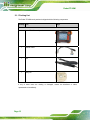
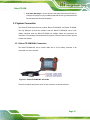
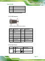
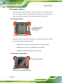
1
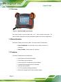
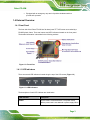
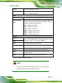
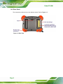
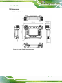
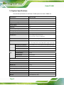
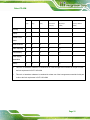
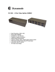
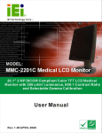
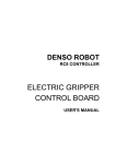
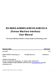
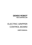
Robot-TP-65M MODEL: Robot-TP-65M Teach Pendant with 4-wire Resistive Type Touchscreen, Deadman Switch, Emergency Button, IP 64 Protection and RoHS User Manual Page I Rev. 1.01 - 7 October, 2013 Robot-TP-65M Revision Date Version Changes 7 October, 2013 1.01 Added Section 3.3.2: Robot-TP-65M/K Connection 17 June, 2013 1.00 Initial release Page II Robot-TP-65M Copyright COPYRIGHT NOTICE The information in this document is subject to change without prior notice in order to improve reliability, design and function and does not represent a commitment on the part of the manufacturer. In no event will the manufacturer be liable for direct, indirect, special, incidental, or consequential damages arising out of the use or inability to use the product or documentation, even if advised of the possibility of such damages. This document contains proprietary information protected by copyright. All rights are reserved. No part of this manual may be reproduced by any mechanical, electronic, or other means in any form without prior written permission of the manufacturer. TRADEMARKS All registered trademarks and product names mentioned herein are used for identification purposes only and may be trademarks and/or registered trademarks of their respective owners. Page III Robot-TP-65M Table of Contents 1 INTRODUCTION.......................................................................................................... 1 1.1 OVERVIEW.................................................................................................................. 2 1.2 MODEL VARIATION ..................................................................................................... 2 1.3 FEATURES ................................................................................................................... 2 1.4 EXTERNAL OVERVIEW ................................................................................................ 3 1.4.1 Front Panel ........................................................................................................ 3 1.4.1.1 LED Indicators............................................................................................ 3 1.4.1.2 Function Keys ............................................................................................. 4 1.4.2 Rear Panel ......................................................................................................... 6 1.5 DIMENSIONS ............................................................................................................... 7 1.6 SYSTEM SPECIFICATIONS ............................................................................................ 8 2 UNPACKING ............................................................................................................... 10 2.1 UNPACKING ...............................................................................................................11 2.1.1 Packing List ..................................................................................................... 12 3 INSTALLATION ......................................................................................................... 13 3.1 ANTI-STATIC PRECAUTIONS ...................................................................................... 14 3.2 INSTALLATION PRECAUTIONS ................................................................................... 14 3.3 SYSTEM CONNECTION .............................................................................................. 15 3.3.1 Robot-TP-65M/K-ML Connection ................................................................... 15 3.3.2 Robot-TP-65M/K Connection .......................................................................... 17 3.3.2.1 OSD Keypad Connector ........................................................................... 18 3.3.2.2 Touch Connector ....................................................................................... 18 3.3.2.3 VGA Connector......................................................................................... 19 3.3.2.4 Cable Pinouts ............................................................................................ 19 3.4 CARRYING THE SYSTEM ........................................................................................... 21 3.5 EMERGENCY BUTTONS ............................................................................................. 22 3.5.1 Deadman Switch .............................................................................................. 22 3.5.2 Emergency Stop Button .................................................................................... 22 A SAFETY PRECAUTIONS ......................................................................................... 24 Page IV Robot-TP-65M A.1 SAFETY PRECAUTIONS ............................................................................................ 25 A.1.1 General Safety Precautions ............................................................................. 25 A.1.2 Anti-static Precautions .................................................................................... 26 A.1.3 Product Disposal ............................................................................................. 27 A.2 MAINTENANCE AND CLEANING PRECAUTIONS ........................................................ 27 A.2.1 Maintenance and Cleaning.............................................................................. 27 A.2.2 Cleaning Tools ................................................................................................. 28 B HAZARDOUS MATERIALS DISCLOSURE ......................................................... 29 B.1 HAZARDOUS MATERIAL DISCLOSURE TABLE FOR IPB PRODUCTS CERTIFIED AS ROHS COMPLIANT UNDER 2002/95/EC WITHOUT MERCURY ....................................... 30 Page V Robot-TP-65M List of Figures Figure 1-1: Robot-TP-65M Teach Pendant ...................................................................................2 Figure 1-2: Front View ....................................................................................................................3 Figure 1-3: LED Indicators.............................................................................................................3 Figure 1-4: Function Keys .............................................................................................................4 Figure 1-5: Rear View .....................................................................................................................6 Figure 1-6: Robot-TP-65M Dimensions (mm) ..............................................................................7 Figure 3-1: Robot-TP-65M/K-ML with Cable...............................................................................15 Figure 3-2: 37-pin Military Connector Pinout Locations...........................................................16 Figure 3-3: Robot-TP-65M/K with Cables ...................................................................................17 Figure 3-4: OSD Keypad Connector Pinout Locations .............................................................18 Figure 3-5: Touch Connector Pinout Locations ........................................................................18 Figure 3-6: VGA Connector Pinout Locations ...........................................................................19 Figure 3-7: Hook Locations .........................................................................................................21 Figure 3-8: Carrying the Robot-TP-65M .....................................................................................21 Figure 3-9: Deadman Switch .......................................................................................................22 Figure 3-10: Emergency Stop Button .........................................................................................22 Page VI Robot-TP-65M List of Tables Table 1-1: LED Indicators ..............................................................................................................4 Table 1-2: Function Key Descriptions ..........................................................................................5 Table 1-3: System Specifications..................................................................................................9 Table 3-1: 37-pin Military Connector Pinouts ............................................................................17 Table 3-2: OSD Keypad Connector Pinouts...............................................................................18 Table 3-3: Touch Connector Pinouts..........................................................................................19 Table 3-4: VGA Connector Pinouts.............................................................................................19 Table 3-5: Cable Pinouts..............................................................................................................20 Page VII Robot-TP-65M Chapter 1 1 Introduction Page 1 Robot-TP-65M 1.1 Overview Figure 1-1: Robot-TP-65M Teach Pendant The Robot-TP-65M is teach pendant with a 6.5” 4-wire resistive touchscreen. The Robot-TP-65M is designed for easy and simplified integration into robot arm applications. 1.2 Model Variation The Robot-TP-65M series has two models. The model variation is listed below: Robot-TP-65M/K-ML: one cable with a 37-pin military connector for connection Robot-TP-65M/L: multiple cables for connection 1.3 Features The Robot-TP-65M features are listed below: Page 2 High brightness LCD with LED backlight 4-wire resistive type touchscreen 6-meter long all-in-one cable allows easy installation Completely dust and splash proof (IP 64) design One meter drop resistance 0°C~50°C extended operating temperature Allow users to program with 33-key membrane keypad Robot-TP-65M Equipped with an emergency stop and a 3-position deadman switch to provide safe operation 1.4 External Overview 1.4.1 Front Panel The front side of the Robot-TP-65M is a flat bezel panel TFT LCD screen surrounded by a PC/ABS plastic frame. There are buttons and LED indicators located on the front panel. The detailed information is described in the following sections. Figure 1-2: Front View 1.4.1.1 LED Indicators There are several LED indicators located along the top of the LCD screen (Figure 1-3). Figure 1-3: LED Indicators The descriptions of each LED indicator are listed below. LED Indicator Description Power On: the robot is connected with a +12V power source Off: the power cord is not attached or power supply failure Page 3 Robot-TP-65M LED Indicator Description Ready On: the robot is turned on and ready to be operated Auto On: the Robot-TP-65M is in Auto mode Servo On: the servo is enabled Off: the servo is disabled. On: the deadman switch is pressed Enable Off: the deadman switch is not pressed Table 1-1: LED Indicators 1.4.1.2 Function Keys The function keys are located on the front side of the Robot-TP-65M (Figure 1-4). Figure 1-4: Function Keys The function keys are described in Table 1-2: Key Function Key Description Left Arrow Keys Use the arrow keys to move the cursor on the screen. OK Use the OK button to confirm. Page 4 Robot-TP-65M Cancel Use the Cancel button to cancel. Speed -/+ Use “-“ to decrease the speed. Use “+“ to increase the speed. Right Stop Use the Stop button to stop the operation. Moving Direction Use these keys to drive the robot arm manually in a designated Keys direction. The user have to hold down the deadman switch at the same time when using these keys. J1/X -/+: Motion in X direction J2/Y -/+: Motion in Y direction J3/Z -/+: Motion in Z direction J4/Rx -/+: Rotation around X axis J5/Ry -/+: Rotation around Y axis J6/Rz -/+: Rotation around Z axis Bottom F1 ~ F6 F1 to F6 are function keys. These function keys can be Shift switched to F7 to F12 by pressing the Shift key. Start Use the Start button to start the motor. Use the Servo button to enable or disable servo. If enabled, the Servo Servo LED indicator on the top of the front panel will light up. Lock Use the Lock button to place the robot in machine lock MOD Use the MOD button to switch between joint, X-Y or tool coordinate mode. Use the Menu button to bring up the menu list. Menu Table 1-2: Function Key Descriptions NOTE: Most of the front panel function buttons are active only when using the optional operator HMI (Human Machine Interface). Page 5 Robot-TP-65M 1.4.2 Rear Panel The rear panel provides access to the deadman switch. Refer to Figure 1-5. Figure 1-5: Rear View Page 6 Robot-TP-65M 1.5 Dimensions The Robot-TP-65M dimensions are shown below. Figure 1-6: Robot-TP-65M Dimensions (mm) Page 7 Robot-TP-65M 1.6 System Specifications The technical specifications for the Robot-TP-65M systems are listed in Table 1-4. Specification Robot-TP-65M LCD Size 6.5" Max. Resolution 640 (W) x 480 (H) Brightness (cd/m2) 800 Contrast Ratio 600:1 LCD Color 262K Pixel Pitch (H x V) (mm) 0.207(H) x 0.207 (V) Viewing Angle (H-V) 160° / 140° Backlight MTBF (hr) 50,000 (LED backlight) Touchscreen 4-wire resistive type touch screen Touch controller: Penmount DMC6000 LED Indicators Five LEDs: Power, Ready, Auto, Servo, Enable Keys Moving direction, OK, Cancel, Speed (-/+), Shift, Function Keys (F1 ~ F6), Start, Servo, Lock, MOD, Menu, Stop, Cursor Keys Switches I/O Emergency Stop Button For B contacts, four circuit outputs (forced disjunction type) Deadman Switch 3-position switch (off-on-off), two circuit outputs Mode Selector Switch 3-position (Auto, Manual, Teach) keylock switch Video Input VGA Touch Interface RS-232 Power Source 12 V DC input Keypad Control Interface PS/2 OSD Control Software OSD Construction Material PC + ABS plastic front frame Front Panel Color Gray Pantone 8405C Weight (N) 3.32 kg Dimensions (W x H x D) (mm) 281 x 200 x 83 Operating Temperature 0ºC ~ 50ºC Storage Temperature -25ºC ~ 65ºC Humidity <90% (no-condensing) IP level IP 64 compliant (6-side) Page 8 Robot-TP-65M Vibration MIL-STD-810F Drop Survival 1 m (38 inches), four corners, two sides Power Requirement 12V DC Power Consumption 6.6 W Cable Length 6m Table 1-3: System Specifications Page 9 Robot-TP-65M Chapter 2 2 Unpacking Page 10 Robot-TP-65M 2.1 Unpacking To unpack the Robot-TP-65M, follow the steps below: WARNING! The front side LCD screen has a protective plastic cover stuck to the screen. Only remove the plastic cover after the Robot-TP-65M has been properly installed. This ensures the screen is protected during the installation process. Step 1: Use box cutters, a knife or a sharp pair of scissors that seals the top side of the external (second) box. Step 2: Open the external (second) box. Step 3: Use box cutters, a knife or a sharp pair of scissors that seals the top side of the internal (first) box. Step 4: Lift the monitor out of the boxes. Step 5: Remove both polystyrene ends, one from each side. Step 6: Pull the plastic cover off the Robot-TP-65M. Step 7: Make sure all the components listed in the packing list are present. Step 0: Page 11 Robot-TP-65M 2.1.1 Packing List The Robot-TP-65M teach pendant is shipped with the following components: Quantity Item Image Standard 1 Robot-TP-65M teach pendant 1 Transfer cable 1 Belt 1 Utility CD If any of these items are missing or damaged, contact the distributor or sales representative immediately. Page 12 Robot-TP-65M Chapter 3 3 Installation Page 13 Robot-TP-65M 3.1 Anti-static Precautions WARNING: Failure to take ESD precautions during the maintenance of the Robot-TP-65M may result in permanent damage to the Robot-TP-65M and severe injury to the user. Electrostatic discharge (ESD) can cause serious damage to electronic components, including the Robot-TP-65M. Dry climates are especially susceptible to ESD. It is therefore critical that whenever the Robot-TP-65M is accessed internally, or any other electrical component is handled, the following anti-static precautions are strictly adhered to. Wear an anti-static wristband: - Wearing a simple anti-static wristband can help to prevent ESD from damaging the board. Self-grounding: - Before handling the board touch any grounded conducting material. During the time the board is handled, frequently touch any conducting materials that are connected to the ground. Use an anti-static pad: - When configuring the Robot-TP-65M, place it on an antic-static pad. This reduces the possibility of ESD damaging the Robot-TP-65M. Only handle the edges of the PCB: - When handling the PCB, hold the PCB by the edges. 3.2 Installation Precautions When installing the Robot-TP-65M, please follow the precautions listed below: Power turned off: When installing the Robot-TP-65M, make sure the power is off. Failing to turn off the power may cause severe injury to the body and/or damage to the system. Certified Engineers: Only certified engineers should install and modify onboard functionalities. Page 14 Robot-TP-65M Anti-static Discharge: If a user open the rear panel of the Robot-TP-65M, to configure the jumpers or plug in added peripheral devices, ground themselves first and wear and anti-static wristband. 3.3 System Connection The Robot-TP-65M series has two models: Robot-TP-65M/K-ML and Robot-TP-65M/K. The only difference of these two models is that the Robot-TP-65M/K-ML has a 37-pin military connector while the Robot-TP-65M/K has multiple cables and connectors for connection. The following sections describe the system connection and connector pinouts of these two models. 3.3.1 Robot-TP-65M/K-ML Connection The Robot-TP-65M/K-ML has a 6-meter cable with a 37-pin military connector to be connected to a robot controller. Figure 3-1: Robot-TP-65M/K-ML with Cable The pinout locations and pinouts of the 37-pin connector are described below. Page 15 Robot-TP-65M Figure 3-2: 37-pin Military Connector Pinout Locations PIN NO. DESCRIPTION PIN NO. DESCRIPTION 1 Key SW. - Manual 20 RS-232 – SOUT 2 EMG2 21 -- 3 EMG1 22 RS-232 – RTS 4 PS/2 - KBDATA 23 PS/2 - GND 5 RS-232 - GND 24 LED - Servo 6 PS/2 - chassis 25 LED – Auto 7 RS-232 - chassis 26 GND 8 PS/2 - KBCLK 27 DDC – DAT 9 -(N) 28 DDC CLOCK 10 LED - Enable A R (Red+) 11 LED - Ready B GND (Red-) 12 +(P) C G (Green+) 13 3 SW.2 D GND (Green-) 14 3 SW.1 E B (Blue+) 15 Key SW. - Teach F GND (Blue-) 16 +12V G VSYNC 17 GND H HSYNC Page 16 Robot-TP-65M 18 RS/2 +5V 19 RS-232 – SIN J Copper Shielding Mesh Table 3-1: 37-pin Military Connector Pinouts 3.3.2 Robot-TP-65M/K Connection The Robot-TP-65M/K has following cables and connectors for connecting to a robot controller: OSD keypad connector (PS/2) Touch connector (DB-9 male) VGA connector (DB-15 male) Cables: o o o o o Monitor power EMG Key switch 3-way switch LED Figure 3-3: Robot-TP-65M/K with Cables The pinout locations and pinouts of these connectors are described in the following sections. Page 17 Robot-TP-65M 3.3.2.1 OSD Keypad Connector Figure 3-4: OSD Keypad Connector Pinout Locations PIN NO. DESCRIPTION 1 KB_DATA 2 -- 3 GND 4 PS/2 VCC_IN 5V 5 KB_CLK 6 -- Table 3-2: OSD Keypad Connector Pinouts 3.3.2.2 Touch Connector Figure 3-5: Touch Connector Pinout Locations PIN NO. DESCRIPTION 1 -- 2 RS-232_RX 3 RS-232_TX 4 -- 5 GND Page 18 Robot-TP-65M 6 -- 7 RS-232_RTS 8 -- 9 -- Table 3-3: Touch Connector Pinouts 3.3.2.3 VGA Connector Figure 3-6: VGA Connector Pinout Locations PIN NO. DESCRIPTION PIN NO. DESCRIPTION 1 RED 9 -- 2 GREEN 10 -- 3 BLUE 11 -- 4 -- 12 DDC_DATA 5 GND 13 HSYNC 6 (Shield) RED 14 VSYNC 7 (Shield) GREEN 15 DDC_CLOCK 8 -- Table 3-4: VGA Connector Pinouts 3.3.2.4 Cable Pinouts Monitor NO. COLOR DESCRIPTION 1 White Vin-in (12V only) 2 Black GND Power Page 19 Robot-TP-65M EMG Key 1 Red EMG 1 2 Yellow EMG 2 1 Black 3 SW.2 2 Brown KEY SW-Teach 3 Orange KEY SW-Manual 1 Green 3 SW.2 2 Blue 3 SW.1 1 Purple LED_Power (VCC 12~24V) 2 Gray LED_Ready 3 White LED_Auto 4 Pink LED_Servo 5 Light green LED_Enable 6 White/Black LED_GND Switch 3-Way Switch LED Table 3-5: Cable Pinouts Page 20 Robot-TP-65M 3.4 Carrying the System The package comes with a belt for the user to carry the Robot-TP-65M. To use the belt, follow the steps below. Step 1: Locate the hooks on the four corners of the Robot-TP-65M (Figure 3-7). Figure 3-7: Hook Locations Step 2: Choose either two hooks to install the belt. Step 3: Carry the Robot-TP-65M as shown in Figure 3-8. Figure 3-8: Carrying the Robot-TP-65M Page 21 Robot-TP-65M 3.5 Emergency Buttons The Robot-TP-65M teach pendant has a deadman switch and an emergency button, which are provided to stop the robot automatically and safely when the operator can no longer operate the robot correctly with the teach pendant in the manual mode. 3.5.1 Deadman Switch Figure 3-9: Deadman Switch The deadman switch is located on the rear panel. It is a 3-position switch which is able to react to the following three operating statuses: (1) OFF: When the switch is not being pressed or is being pressed lightly (2) ON: When the switch is being pressed with correct pressure (3) OFF: When the switch is being pressed too strongly 3.5.2 Emergency Stop Button Figure 3-10: Emergency Stop Button Page 22 Robot-TP-65M The emergency stop button is located on the front panel. Push the button can stop the robot operation immediately. STOP: Push the emergency stop button to stop operation. RESET: o o Pull the emergency stop button to reset or Turn the emergency stop button to rest Page 23 Robot-TP-65M Appendix A A Safety Precautions Page 24 Robot-TP-65M WARNING: The precautions outlined in this chapter should be strictly followed. Failure to follow these precautions may result in permanent damage to the Robot-TP-65M. A.1 Safety Precautions Please follow the safety precautions outlined in the sections that follow: A.1.1 General Safety Precautions Please ensure the following safety precautions are adhered to at all times. Follow the electrostatic precautions outlined below whenever the Robot-TP-65M is opened. Make sure the power is turned off and the power cord is disconnected whenever the Robot-TP-65M is being installed, moved or modified. Do not apply voltage levels that exceed the specified voltage range. Doing so may cause fire and/or an electrical shock. Electric shocks can occur if the Robot-TP-65M chassis is opened when the Robot-TP-65M is running. Do not drop or insert any objects into the ventilation openings of the Robot-TP-65M. If considerable amounts of dust, water, or fluids enter the Robot-TP-65M, turn off the power supply immediately, unplug the power cord, and contact the Robot-TP-65M vendor. DO NOT: o o o o Drop the Robot-TP-65M against a hard surface. Strike or exert excessive force onto the LCD panel. Touch any of the LCD panels with a sharp object In a site where the ambient temperature exceeds the rated temperature Page 25 Robot-TP-65M A.1.2 Anti-static Precautions WARNING: Failure to take ESD precautions during the installation of the Robot-TP-65M may result in permanent damage to the Robot-TP-65M and severe injury to the user. Electrostatic discharge (ESD) can cause serious damage to electronic components, including the Robot-TP-65M. Dry climates are especially susceptible to ESD. It is therefore critical that whenever the Robot-TP-65M is opened and any of the electrical components are handled, the following anti-static precautions are strictly adhered to. Wear an anti-static wristband: Wearing a simple anti-static wristband can help to prevent ESD from damaging any electrical component. Self-grounding: Before handling any electrical component, touch any grounded conducting material. During the time the electrical component is handled, frequently touch any conducting materials that are connected to the ground. Use an anti-static pad: When configuring or working with an electrical component, place it on an antic-static pad. This reduces the possibility of ESD damage. Only handle the edges of the electrical component: When handling the electrical component, hold the electrical component by its edges. Page 26 Robot-TP-65M A.1.3 Product Disposal CAUTION: Risk of explosion if battery is replaced by and incorrect type. Only certified engineers should replace the on-board battery. Dispose of used batteries according to instructions and local regulations. Outside the European Union - If you wish to dispose of used electrical and electronic products outside the European Union, please contact your local authority so as to comply with the correct disposal method. Within the European Union: EU-wide legislation, as implemented in each Member State, requires that waste electrical and electronic products carrying the mark (left) must be disposed of separately from normal household waste. This includes monitors and electrical accessories, such as signal cables or power cords. When you need to dispose of your display products, please follow the guidance of your local authority, or ask the shop where you purchased the product. The mark on electrical and electronic products only applies to the current European Union Member States. Please follow the national guidelines for electrical and electronic product disposal. A.2 Maintenance and Cleaning Precautions When maintaining or cleaning the Robot-TP-65M, please follow the guidelines below. A.2.1 Maintenance and Cleaning Prior to cleaning any part or component of the Robot-TP-65M, please read the details below. Page 27 Robot-TP-65M Except for the LCD panel, never spray or squirt liquids directly onto any other components. To clean the LCD panel, gently wipe it with a piece of soft dry cloth or a slightly moistened cloth. Never use alcohol to clean the external chassis. The interior of the Robot-TP-65M does not require cleaning. Keep fluids away from the Robot-TP-65M interior. Be cautious of all small removable components when vacuuming the Robot-TP-65M. Turn the Robot-TP-65M off before cleaning the Robot-TP-65M. Never drop any objects or liquids through the openings of the Robot-TP-65M. Be cautious of any possible allergic reactions to solvents or chemicals used when cleaning the Robot-TP-65M. Avoid eating, drinking and smoking within vicinity of the Robot-TP-65M. A.2.2 Cleaning Tools Some components in the Robot-TP-65M may only be cleaned using a product specifically designed for the purpose. In such case, the product will be explicitly mentioned in the cleaning tips. Below is a list of items to use when cleaning the Robot-TP-65M. Cloth – Although paper towels or tissues can be used, a soft, clean piece of cloth is recommended when cleaning the Robot-TP-65M. Water – A cloth moistened with water can be used to clean the Robot-TP-65M. Using solvents – The use of solvents is not recommended when cleaning the Robot-TP-65M as they may damage the plastic parts. Vacuum cleaner – Using a vacuum specifically designed for computers is one of the best methods of cleaning the Robot-TP-65M. Dust and dirt can restrict the airflow in the Robot-TP-65M and cause its circuitry to corrode. Cotton swabs - Cotton swaps moistened with water are excellent tools for wiping hard to reach areas. Foam swabs - Whenever possible, it is best to use lint free swabs such as foam swabs for cleaning. Page 28 Robot-TP-65M Appendix B B Hazardous Materials Disclosure Page 29 Robot-TP-65M B.1 Hazardous Material Disclosure Table for IPB Products Certified as RoHS Compliant Under 2002/95/EC Without Mercury The details provided in this appendix are to ensure that the product is compliant with the Peoples Republic of China (China) RoHS standards. The table below acknowledges the presences of small quantities of certain materials in the product, and is applicable to China RoHS only. A label will be placed on each product to indicate the estimated “Environmentally Friendly Use Period” (EFUP). This is an estimate of the number of years that these substances would “not leak out or undergo abrupt change.” This product may contain replaceable sub-assemblies/components which have a shorter EFUP such as batteries and lamps. These components will be separately marked. Please refer to the table on the next page. Page 30 Robot-TP-65M Part Name Toxic or Hazardous Substances and Elements Lead Mercury Cadmium Hexavalent Polybrominated Polybrominated (Pb) (Hg) (Cd) Chromium Biphenyls Diphenyl Ethers (CR(VI)) (PBB) (PBDE) Housing X O O O O X Display X O O O O X Printed Circuit X O O O O X Metal Fasteners X O O O O O Cable Assembly X O O O O X Fan Assembly X O O O O X Power Supply X O O O O X O O O O O O Board Assemblies Battery O: This toxic or hazardous substance is contained in all of the homogeneous materials for the part is below the limit requirement in SJ/T11363-2006 X: This toxic or hazardous substance is contained in at least one of the homogeneous materials for this part is above the limit requirement in SJ/T11363-2006 Page 31 Robot-TP-65M 此附件旨在确保本产品符合中国 RoHS 标准。以下表格标示此产品中某有毒物质的含量符 合中国 RoHS 标准规定的限量要求。 本产品上会附有”环境友好使用期限”的标签,此期限是估算这些物质”不会有泄漏或突变”的 年限。本产品可能包含有较短的环境友好使用期限的可替换元件,像是电池或灯管,这些元 件将会单独标示出来。 部件名称 有毒有害物质或元素 铅 汞 镉 六价铬 多溴联苯 多溴二苯醚 (Pb) (Hg) (Cd) (CR(VI)) (PBB) (PBDE) 壳体 X O O O O X 显示 X O O O O X 印刷电路板 X O O O O X 金属螺帽 X O O O O O 电缆组装 X O O O O X 风扇组装 X O O O O X 电力供应组装 X O O O O X 电池 O O O O O O O: 表示该有毒有害物质在该部件所有物质材料中的含量均在 SJ/T11363-2006 标准规定的限量要求以下。 X: 表示该有毒有害物质至少在该部件的某一均质材料中的含量超出 SJ/T11363-2006 标准规定的限量要求。 Page 32