1
User Manual
For SL Series
Smart & Accurate
Preface
.
This manual is a user guide that provides the information on how to install, operate and maintain
SA series AC servo drive. The contents of this manual include the following topics:
● Installation of AC servo drives and motors
● Configuration and wiring
● Trial run steps
● Control functions and adjusting methods of AC servo drives
● Parameter settings
● Inspection and maintenance
● Troubleshooting
● Application examples
Before using the product, please read this manual to ensure correct use. Users should thoroughly
understand all safety precautions (DANGERS and WARNINGS) before proceeding with the
installation, wiring and operation. If you still have any problem, please contact with the local
Bonmet sales representative. Place this user manual in a safe location for future reference.
1
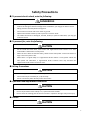
Safety Precautions
● To prevent electric shock, note the following:
DANGEROUS
·
Before wiring or inspection, switch power off and wait for more than 10 minutes. Then,
confirm the voltage is safe with voltage tester. Otherwise, you may get an electric shock.
·
·
·
·
Wiring must be carried by electrical engineer.
Connect the servo drive and servo motor to ground.
Operate the switches with dry hand to prevent an electric shock.
The cables should not be damaged, stressed, loaded, or pinched. Otherwise, you may get
an electric shock.
● To prevent fire, note the following:
CAUTION
·
Do not install the servo drive, servo motor and regenerative brake resistor on or near
combustibles. Otherwise a fire may cause.
·
When the servo drive has become faulty, switch off the main power. Continuous flow of a
large current may cause a fire.
·
When there is a signal faulty as a regenerative brake resistor is used, please switch the
main power off. Otherwise, a regenerative brake transistor fault may overheat the
regenerative brake resistor and cause a fire.
● Wiring Precautions
CAUTION
·
·
·
Wire the equipment correctly and securely.
Connect the output terminals (U, V, W) correctly.
Do not connect AC power directly to the servo motor.
● Operation and Adjustment Precautions
CAUTION
· Do not touch the radiator and the regenerative brake resistor as they are overheated.
· Do not set parameter value unduly. If so, system would be instable.
· Do not touch the rotating parts of the servo motor in operation. Doing so may cause injury.
● Others
CAUTION
·
Do not attempt to remold the servo drive.
2
CONTENTS
CHAPTER 1
MODEL AND SPECIFICATIONS .............................................................................................. 5
1.1
NAMEPLATE ................................................................................................................................. 5
1.2
MODEL DESIGNATION ..................................................................................................................... 5
1.3
OUTLINE DIMENSION DRAWINGS (UNIT: MM )........................................................................................ 5
1.4
TECHNICAL SPECIFICATIONS .............................................................................................................. 6
1.4.1
General Specifications ............................................................................................................ 6
CHAPTER 2
WIRING AND OPERATION ................................................................................................... 7
2.1
INSTALLATION SITES ........................................................................................................................ 7
2.2
INSTALLATION DIRECTION AND SPACE .................................................................................................. 7
2.3
CONNEC TION ............................................................................................................................... 7
2.4
SCHEMATIC DIAGRAM O F POSITION C ONTROL MODE ............................................................................... 8
CHAPTER 3
INTERFACE ......................................................................................................................... 9
3.1
TERMINALS .................................................................................................................................10
3.2
POWER TERMINAL ........................................................................................................................10
3.3
ENCODER CONNECTOR CN1 ............................................................................................................10
3.3
3.4
I/O C ONNECTOR CN2 ...................................................................................................................10
LINE-LINE SERIAL TERMINAL COM/CN3 .............................................................................................12
3.5
3.5.1
I/O INTERFACE TYPE ......................................................................................................................12
Switching Input Interface .......................................................................................................12
3.5.2
Switching Output Interface ....................................................................................................12
3.5.3
3.5.4
Pulse Input Interface .............................................................................................................13
Analog Input Interface...........................................................................................................15
3.5.5
3.5.6
Encoder Signal Output Interface .............................................................................................16
Open Collector Output Interface for Encoder Phase-Z Signal......................................................17
3.5.7
Optical Encoder Input Interface for Servo Motor ......................................................................18
CHAPTER 4
OPERATION.......................................................................................................................18
4.1
OPERA TION PROC EDURE .................................................................................................................18
4.2
4.2.1
PREPA RING F OR OP ERA TION ............................................................................................................19
Turning Power ON and Checking Indicators .............................................................................19
4.3
4.3.1
4.3.2
4.4
POSITION C ONTROL M ODE ..............................................................................................................19
Parameters In Position Control Mode .....................................................................................20
Operation ............................................................................................................................20
SPEED MODE ..............................................................................................................................20
4.4.1
Parameters In Speed Control Mode ........................................................................................21
4.4.2
Operation ............................................................................................................................21
4.5
4.5.1
4.5.2
TORQUE C ONTROL M ODE ...............................................................................................................22
Parameters In Torque Control Mode .......................................................................................22
Operation ............................................................................................................................22
4.6
4.6.1
GAIN ADJ USTM ENT .......................................................................................................................22
Speed Loop...........................................................................................................................23
4.6.2
4.6.3
Position Loop........................................................................................................................23
Parameters Settings ..............................................................................................................23
3
CHAPTER 5
PARAMETERS ....................................................................................................................24
5.1
PARAMETER LIST ..........................................................................................................................24
5.2
PARAMETER C ONTENTS ..................................................................................................................30
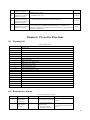
CHAPTER 6
PROTECTIVE FUNCTIONS ....................................................................................................43
6.1
WARNING LIST ............................................................................................................................43
6.2
REMEDIES FOR ALARMS ..................................................................................................................43
4
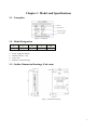
Chapter 1 Model and Specifications
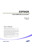
1.1 Nameplate
Model
Input Power
Nominal Output
Serial Number
Figure 1-1 Nameplate
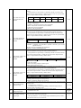
1.2 Model Designation
S
1
L
2
10
3
A
4
XX
5
1. Product type: S- Series DC servo drive;
2. Power supply:48~80VDC
3. Nominal current:10A
4. Type code;
5. Software customized logo.
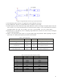
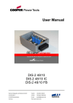
1.3 Outline Dimension Drawings (Unit: mm)
Figure 1-1 Dimension drawings
5
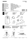
1.4 Technical Specifications
1.4.1 General Specifications
Input power supply
Ambient
temperature
Ambient humidity
Atmospheric
pressure
Control mode
Speed frequency
response
Speed
Features
fluctuation ratio
Speed ratio
Pulse frequency
Input signals
Output signals
Operation
environment
Position control mode
Speed control mode
Acceleration and
48~80VDC
Operation:0~40℃ Storage:-40℃~50℃
40%~80%( non-condensing)
86~106kPa
①Position ②Speed ③Torque
≥300Hz
<±0.03(Load 0~100%);<±0.02(Power Supply -15~+10%)
(Value corresponds to the nominal speed)
1:5000
≤500kHz
①Servo enable ②Alarm clear
①Alarm output②Positioning completed / speed reached
①Pulse + Direction
Pulse type
②CCW pulse / CW pulse
③A phase and B phase
Electronic gear
1~32767/1~32767
Feedback pulse
2500 C/T
Four kinds of internal speed
Parameter setting :1~10000ms or 1~1000r/min
deceleration function
M onitoring function
Protective functions
Applicable load inertia
Speed, current position, accumulation of command pulse, position
deviation, motor torque, motor current, linear speed, rotor absolute
position, command pulse frequency, operation state, I/O terminal signals,
etc.
Overspeed, overvoltage, undervoltage, over current, M otor overheated ,
overload, Brake error, encoder error, control power error, location
tolerance, etc.
Less than five times of motor inertia
6
Chapter 2 Wiring and Operation
2.1 Installation Sites
·
Please install the servo system in the place without oil mist, dust or electrical control cabinet (ensure the
temperature below 50℃, relative humidity below 80%. The long-term safety temperature below 40℃).
·
Please install the servo system in the place without radioactive matters and combustibles.
·
Take an anti-vibration measure to guarantee that the servo drive is free from vibration impact, ensuring the
2
vibration under 0.5G (4.9m/s ).
Please install the servo system in the place without direct sunlight.
Interferential equipment nearby would take great effects to the power wire and control wire which will cause
misoperation. For normal operation, a noise filter or any other anti-jamming measures is necessary to be
carried out. Leakage current would increase after installing a noise filter, therefore an isolation transformer
can be used to avoid this problem. Possessing a reasonable alignment and inhibit measures is very important
because the control signal wire is easy to be interfered.
·
·
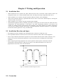
2.2 Installation Direction and Space
· The equipment must be installed in the specified direction. Otherwise, a fault may occur.
· Leave specified clearances between the servo drive and control box inside walls or other equipment.
· Leave a large clearance between the top of the servo drive and the internal surface of the control box, and
install a fan to prevent the internal temperature of the control box from exceeding the environmental
conditions.
· When using heat generating equipment such as the regenerative brake option, install them with full
consideration of heat generation so that the servo drive is not affected. Install the servo drive on a
perpendicular wall in the correct vertical direction.
≥100mm
≥ 25mm
≥25mm
≥100 mm
≥ 100 mm
Ai r flow
Ai r flow
Figure 2-1 installation schematic diagram for drives
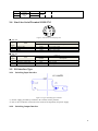
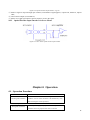
2.3 Connection
7
Controler
Control
Card
Power
48~80VDC
Motor
Figure 2-2 Connection graph
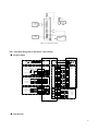
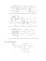
2.4 Schematic Diagram Of Position Control Mode
● Position mode
Motor 4 Core
Pin
+85VDC
+VDC
GND
GND
CN2
DC
12~24V
4.7K
ServoEn+
Servo Enable
Alarm Clear
ServoEn-
20
19
AlarmClr+
3
AlarmClr-
12
4.7K
CN2
Servo Alarm
Orientation
Complete
ALM +
5
ALM -
14
COIN +
4
COIN -
13
U
V
W
CN1
2
3
4
Receiver
12
5V
2
13
0V
3
1
A +
6
A -
4
7
5
8
2
B +
7
B -
3
Z +
6
8
4
Z -
9
U +
10
9
5
U -
13
V +
11
10
V -
14
14
W +
12
15
11
W -
15
FG
1
Encoder 15
Core Pin
CN2
Position Command
PULS
PulseInv +
2
PulseInv -
Position Command
SIGN
SignInv +
11
1
SignInv -
10
CN2
220
1
Driver
PhaseA +
2
PhaseA -
3
PhaseB +
4
PhaseB -
5
PhaseZ +
6
PhaseZ -
Encoder
Signal
Output
Figure 2-3 Position mode
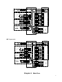
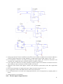
● Speed mode
8
Motor 4 Core
Pin
+85VDC
+VDC
GND
GND
U
V
W
4.7K
ServoEn+
Servo Enable
ServoEn-
Alarm Clear
20
19
AlarmClr+
3
AlarmClr-
12
4.7K
CN2
Servo Alarm
Orientation
Complete
ALM +
5
ALM -
14
COIN +
4
COIN -
13
Receiver
CN1
CN2
DC
12~24V
2
3
4
12
5V
2
13
0V
3
1
A +
6
A -
4
7
5
8
2
B +
7
B -
Encoder 15
Core Pin
3
Z +
6
8
4
Z -
9
U +
10
9
5
U -
13
V +
11
10
V -
14
14
W +
12
15
11
W -
15
FG
1
CN2
Speed Simulation
Command
(-10V~+10V)
+
-
ASPEED+
ASPEED-
AGEND
24
25
26
10k
-
CN2
+
1
Driver
PhaseA +
2
PhaseA -
3
PhaseB +
4
PhaseB -
5
PhaseZ +
6
PhaseZ -
Encoder
Signal
Output
Figure 2-4 Speed mode
● Torque mode
Motor 4 Core
Pin
+85VDC
+VDC
GND
GND
U
V
W
CN1
CN2
DC
12~24V
4.7K
ServoEn+
Servo Enable
Alarm Clear
ServoEn-
20
19
AlarmClr+
3
AlarmClr-
12
4.7K
CN2
Servo Alarm
Orientation
Complete
ALM +
5
ALM -
14
COIN +
4
COIN -
13
2
3
4
Receiver
12
5V
2
13
0V
3
1
A +
6
A -
4
7
5
8
2
B +
7
B -
3
Z +
6
8
4
Z -
9
U +
10
9
5
U -
13
V +
11
10
V -
14
14
W +
12
15
11
W -
15
FG
1
Encoder 15
Core Pin
CN2
Torque Simulation +
Instruction
(-10V~+10V)
ATORQUE+
ATORQUE-
AGEND
24
25
26
10k
-
CN2
+
1
Driver
PhaseA +
2
PhaseA -
3
PhaseB +
4
PhaseB -
5
PhaseZ +
6
PhaseZ -
Encoder
Signal
Output
Figure 2-4 Torque mode
Chapter 3 Interface
9
3.1 Terminals
Terminal
+VDC、GND
U、V、W
CN1
CN2
COM
Name
Drive power terminal
M otor terminal
Encoder Connector
I/O Connector
Communication Connector
Function
Connect
Connect
Connect
I/O port
Connect
with 48~80VDC
with motor
with encoder
with PC or controller
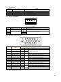
3.2 Power Terminal
1
2
3
4
5
Figure 3-1 Power terminal
端子号
1
2
3
4
5
名称
端子记号
GND
+VDC
U
V
W
Ground
Power
M otor U、V、W terminal
说明
Connect with OV
Connect with 48~80V
Connect with motor power terminal
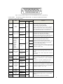
3.3 Encoder Connector CN1
5
4
10
15
2
3
9
14
7
8
13
1
12
6
11
Figure 3-2 Encoder Connector (face to plug-welding)
Function
Symbol
I/O
Description
Terminal
number
Name
12
Power supply(5V)
+5V
13
Public ground
0V
1
6
2
7
3
8
4
9
5
10
14
15
Encoder A+ input
Encoder A- input
Encoder B+ input
Encoder B- input
Encoder Z+ input
Encoder Z- input
Encoder U+ input
Encoder U- input
Encoder V+ input
Encoder V- input
Encoder W+ input
Encoder W- input
A+
A-
B+
B-
Z+
Z-
U+
U-
V+
V-
W+
W-
11
Inhibit ground
FG
The power supply and public ground of encoder. It is
necessary to use a parallel multi-cored wire to reduce
the pressure drop of wires.
Type7
Type7
Type7
Type7
Type7
Type7
Connect
Connect
Connect
Connect
Connect
Connect
Connect
Connect
Connect
Connect
Connect
Connect
with the electro-optic encoder A+.
with the electro-optic encoder A-.
with the electro-optic encoder B+.
with the electro-optic encoder B-.
with the electro-optic encoder Z+.
with the electro-optic encoder Z-.
with the electro-optic encoder U+.
with the electro-optic encoder U-.
with the electro-optic encoder V+.
with the electro-optic encoder V-.
with the electro-optic encoder W+.
with the electro-optic encoder W-.
Terminal of Inhibit ground
3.3 I/O Connector CN2
10
9
8
18
7
26
5
6
16
17
15
25 24
4
14
23
2
3
13
22
12
21
1
11
20
10
19
Figure 3-2 Plug-welding of plug CN2 (encoder FEEDBACK) (face to plug-welding)
Control mode: P stands for position control mode;S stands for speed control mode;
T stands for torque control mode.
Termina
l
number
Terminal symbol
Name
20
Symbol
I/O
mode
Servo enable input terminal.
ServoEn ON: Operation enabled;
ServoEn OFF: Operation disabled.
[Note 1]: M ake sure the servo motor is quiescent
before “ServoEn OFF” turns to “ServoEn ON”
[Note 2]: Please wait for 50 ms before inputting
any command in the State of “ServoEn ON”.
ServoEn+
Servo
enable
Type1
19
ServoEn-
3
AlarmClr+
Function
Alarm clear input terminal.
Alarm clear
12
4
13
AlarmClr-
Positioning
completed
output
(position
control);
speed
reached
output
(speed
control)
5
P
COIN+
S
Type1
P
COIN-
S
14
11
1
10
24
25
26
7
16
8
17
Type2
Alarm-
Command
pulse PLUS
input
PulseInv+
Command
pulse SIGN
input
SignInv+
Analog
command
input
Analog
ground
Encoder
Phase-A
signal
Encoder
phase-B
Type3
P
Type3
P
Type4
S、T
PulseInv-
SignInv-
ASPEED+/
ATORQUE
+
ASPEED-/
ATORQUE
-
AGND
PhaseB+
PhaseB-
External command pulse input terminal.
Note: pulse type is selected by parameter PN52.
①PN52=0, command pulse+ signal mode(default
state);
②PN52=1, CCW/CW command pulse mode;
③PN52=2, 2-phase command pulse mode.
Command input terminal for external analog
torque/speed (difference mode), the impedance is
10kΩ, the voltage is -10V~+10V.
The grounding line of analog input.
PhaseA+
PhaseA-
Positioning completed output terminal:
COIN ON:Positioning completed terminal
outputs ON as the value of position offset counter
is in the setting range, otherwise outputs OFF;
Speed reached output terminal:
COIN ON:Speed reached terminal outputs ON as
the speed is equal to or over the selected speed,
otherwise outputs OFF;
Output terminal of servo alarm.
ALM ON: Servo alarm output ON as there is no
alarm;
ALM OFF: Servo alarm output OFF as there is
any alarm.
Alarm+
Servo alarm
output
2
AlarmClr ON: Clear the system alarm;
AlarmClr OFF: M aintain the system alarm.
[Note]: As the alarm code is less than 12, please
cut off the power supply and repair the drive.
Type1
Type5
Type5
1. Encoder signal A, B, Z for difference drive
output (output through 26LS31, corresponding to
RS422 );
2. Non-isolative output (non-insulation).
11
9
18
signal
Encoder
phase- Z
signal
PhaseZ+
PhaseZ-
Type5
3.4 Line-Line Serial Terminal COM/CN3
1
2
4
3
5
7
6
8
Figure 3-4 Serial-line terminal plug CN3
■ RS-232
Termina
l
number
3
5
1
Function
Name
Symbol
Receive data
Transmit data
GND
RXD
TXD
GND
Description
Receive data signal.
Transmit data signal.
Inhibit signal earth.
■ RS-485
Termina
l
number
8
7
1
Function
Name
Symbol
Difference signal Data+
Difference signal DataGND
Data+
DataGND
Description
Data+ teminal
Data- teminal
Inhibit signal earth.
3.5 I/O Interface Type
3.5.1 Switching Input Inte rface
Figure 3-5 Type1 Switching input interface
(1) Power supply provided by customers, DC12~24V, current≥100mA;
(2) Servo drive could not work in the event of the reversed polarity for power supply.
3.5.2 Switching Output Interface
12
a. Relay connection figure
b. Electro-optical coupler connection figure
Figure 3-6 Type2 switching output interface
(1) The output is the Darington transistor, with relay or electro-optical coupler connection;
(2) The external power supply provided by users may damage the drive because of the reversed polarity;
(3) The output works in collecting electrode opening form, the maximum current is up to 50mA while the
maximum external voltage is 25V. Therefore, the switch output signal's load must satisfy this definition
request. If it surpasses the definition request or the output is directly connected with the power supply will
cause damage.
(4) Users should connect inverse parallel freewheel diode in case of the inductive load such as relays. If the
freewheel diode is reversed, servo drive may be damaged;
(5) As Darlington transistor is used for output, as breakover, the pressure drop(Vce) between collector and launch
is about 1V which could not meet the low -level requirements, so it could not be connected with TTL
integrated circuits directly.
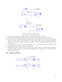
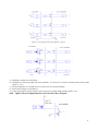
3.5.3 Pulse Input Interface
Figure 3-7 difference drive mode for Type3 pulse input interface
13
Figure 3-8 single-ended drive mode for Type3 pulse input interface
(1) To transmit the pulse correctly, it is suggested to use the difference drive type.
(2) Using AM26LS31, MC3487 or similar RS422 drive in difference drive mode.
(3) Action frequency will be reduced as using single-ended drive mode. According to the pulse input circuit, the
drive current is 10 to 15mA and limitation for external maximum voltage is 25V to determinate the resistance
R. Empirical data: VCC=24V,R=1.3~2kΩ;VCC=12V,R=510~820Ω;VCC=5V,R=82~120Ω.
(4) External power is provided by users as adopting single-ended drive, and the servo drive may be damaged
because of the anti-polarity.
(5) Table 3-1 for pulse input mode, Table 3-2 for pulse input timing and parameter. When operating in 2-phase
input mode, its 4 times pulse frequency will be less than 500 kHz.
Table 3-1 Pulse input mode
Pulse command
CCW
CW
pulse train
PULS
PULS
0
symbol
SIGN
SIGN
Command pulse+symbol
CCW pulse train
PULS
PULS
1
CW pulse train
SIGN
SIGN
CCW pulse/CCW pulse
Phase-A pulse train
PULS
PULS
2
Phase-B pulse train
SIGN
SIGN
2-phase command pulse
Parameter
t ck
th
tl
t rh
t rl
ts
t qck
t qh
t ql
t qrh
t qrl
t qs
Setting value for parameters
Table 3-2 Pulse input mode timing and parameter
Difference drive input
Single-ended drive input
>2μS
>5μS
>1μS
>2.5μS
>1μS
>2.5μS
<0.2μS
<0.3μS
<0.2μS
<0.3μS
>1μS
>2.5μS
>8μS
>10μS
>4μS
>5μS
>4μS
>5μS
<0.2μS
<0.3μS
<0.2μS
<0.3μS
>1μS
>2.5μS
14
Figure 3-9 Pulse and symbol input interface timing chart (The maximum pulse frequency: 500 kHz)
Figure 3-10 CCW /CW pulse input interface timing chart (The maximum pulse frequency: 500 kHz)
Figure 3-11 2-phase command pulse input interface timing chart (The maximum pulse frequency: 125 kHz)
3.5.4 Analog Input Interface
Figure 3-12 (a) Difference analog input interface(type4)
15
Figure 3-12 (b) Single-ended analog input interface(type4)
Figure 3-12 (c) Difference analog potentiometer input interface(type4)
Figure 3-12 (d) Single-ended analog potentiometer input interface(type4)
(1) Analog input interface works in difference mode, there are two modes according to the connection: difference
mode and single-ended mode, the input impedance is 10kΩ and the range of input voltage is-10V~+10V;
(2) In the difference connection, the analog grounding and input negative end should be connected at the
controller side, needing three line connections from the controller to the driver;
(3) In the single end connection, the analog grounding and input negative end should be connected at the drive
side, needing two line connections from the controller to the driver;
(4) Difference mode which could suppress common code interference performances better than single-ended
mode;
(5) Drive may be damaged on condition that input voltage exceeds the range of -10~+10;
(6) It is suggested to connect with inhibit cable to reduce noise interference;
(7) It is normal that there is zero-bias at the analog input interface, you can compensate it by adjusting PN16 or
PN19;
(8) Analog interface is non-insulated.
3.5.5 Encoder Signal Output Interface
16
Figure 3-13 a Optical encoder output interface(Type5)
Figure 3-13 b Optical encoder output interface(Type5)
(1) AM26LS31 outputs encoder signals;
(2) AM26LS32 is used as the input end of the controller,it is necessary to connect a terminal resistor about 330Ω
(Figure 3-13 a);
(3) The grounding line of controller and servo drive must be connected reliably;
(4) Non-isolative output (non-insulative).
(5) A high speed electro-optical coupler can be used as the controller input instead (Figure3-13 b).
3.5.6 Open Collector Output Inte rface for Encoder Phase-Z Signal
17
Figure 3-14 Optical encoder output interface(Type6)
(1) Phase-Z signal is output through open collector, when Phase-Z signal appears, outputs ON, otherwise, outputs
OFF;
(2) Non-isolative output (non-insulative).
(3) Please use a high speed electro-optical coupler to receive the signal.
3.5.7 Optical Encoder Input Interface for Servo Motor
Figure 3-15 Servo motor optical encoder input interface
Chapter 4 Operation
4.1 Operation Procedure
Item
Content
Install the motor and servo drive according to the installation
M ounting and installation
conditions. (Do not connect the motor to the mechanical system
before checking the no-load operation.)
↓
Wiring and connections
Connect to power supply and peripheral devices. Specified
installation and wiring requirements must be satisfied.
18
↓
Before turning ON the power supply, check the necessary items.
Preparing for operation
Check by means of the displays to see whether there are any
internal errors.
↓
Checking operation
Check the operation of the motor and servo driver alone by
performing a jogging operation without a load.
↓
By means of the user parameters, set the functions according to
Function settings
the operating conditions.
↓
Turn on the power, and check whether protective functions such
Trial operation
as emergency stop and operational limits are working reliably.
Check operation at both low speed and high speed (using
instructions from the Host Controller).
↓
M anually adjust the gain as required. Further adjust the various
Adjustments
functions to further improve the control performance as required.
↓
Operation can now begin. If any trouble occurs, refer to Chapter
Operation
4.2
6 Troubleshooting.
Preparing For Operation
4.2.1 Turning Power ON and Checking Indicators
■ Checking Power Supply Voltage
· Check to be sure that the power supply voltage is 48~80VDC
■ Checking Terminal Block Wiring
· The power supply inputs (+VDC、GND)must be properly connected to the terminal block.
· The servo motor’s power line(U、V、W)must be properly connected to the terminal block.
■ Checking the servo motor
· The Encoder Cable must be securely connected to the Encoder Connector at the motor side.
· The power lines at the servo motor must be securely connected.
■ Checking the Control Connectors
· The Control Cable must be securely connected to the I/O Control Connector (CN2 ).。
· The ServoEn command must be OFF
4.3 Position Control Mode
· Perform position control using the pulse train input from PulseInv+(CN2-Pin32),
PulseInv-(CN2-Pin33), SignInv+ (CN2-Pin34), SignInv-( CN2-Pin35).
· The servo motor rotates using the value of the pulse train input multiplied by the electronic gear (Pn48、
Pn49、Pn50)
19
· The encoder line is 2500C/T,users can get feedback signals A+(CN2-Pin7)、A-(CN2-Pin16)、B+
(CN2-Pin8)、B-(CN2-Pin17)、Z+(CN2-Pin9)、Z-(CN2-Pin18)through CN2.
4.3.1 Parameters In Position Control Mode
No.
Parameter
Function
Select the control mode of servo drive.(Set the parameter to 2 for position control
mode)
4
M otor control mode
48
Denominator of position
gearbox
The electronic gear ratio is G N C 4
Divider numerator of the
first position command
pulse
G: Electronic gear ratio;P: Input command pulse number;N: The revolving circle of the
motor; C: The photoelectric encoder C/T, this system is C=2500.
Recommendatory range of electronic gear ratio: 1 G 50
50
49
52
53
54
55
56
57
Position command pulse
input mode
Invert direction of position
command pulse
Positioning completed
range
Range of position
super-homodyne detection
Enable position error
Position pulse feedback
ratio
P
Set the parameter to match with the controller command pulse status.
Select the rotation direction
If the position error drops in the target position range, the output terminal COIN turns
active, otherwise COIN remains inactive.
The drive will issue position tolerance alarm when the position offset counter value
exceeds the selected value×100 in position control mode.
Set the parameter select using the position tolerance alarm or not.
The feedback ratio of position pulse determines the ratio of the internal and output
position pulse.
4.3.2 Ope ration
1. Connect the servo system correctly and turn on the power supply.
2. Select the command pulse type and rotation direction.
①Set Pn52 to choose position command pulse type. Set Pn52 to 0, the position command type is pulse and
symbol; set Pn52 to 1, the position command type is CW/CCW pulse; set Pn52 to 2, the position command
type is two-phase orthogonal pulse.
②Set Pn53 to select the rotation direction. (0 for normal rotation direction and 1 for the opposite rotation
direction)
3. Select electronic gear ratio.
Set Pn48, Pn49 to select proper electronic gear ratios.
4. Running.
Set Pn4 to 2 to select position control mode, set ServoEn(ServoEn+:CN2-Pin20;ServoEn-:CN2-Pin19) ON.
Users can adjust the input pulse to control the motor.
5. Other functions.
①Positioning completed: In position control mode, if the position error drops in the target position range, the
output terminal COIN turns active, otherwise COIN remains inactive.
②Position error function: Set Pn56 to 0, position tolerance alarm detection is enabled; Set Pn56 to 1, position
tolerance alarm detection is disabled and position tolerance error detection is stopped.
③Position pulse feedback ratio: The feedback ratio of position pulse determines the ratio of the internal and
output position pulse: the parameter is a decimal number, change it into a binary, we divide the binary into
two parts, the high-5-bit value is the numerator while the low-5-bit is the denominator , then the fraction is the
feedback ratio (Normal setting: 33 (00001_00001) for 1:1; 34 (00001_00010) for 1:2; 36 (00001_00100) for
1:4; 37 (00001_00101) for 1:5; 42 (00001_01010) for 1:10 ).
4.4 Speed Mode
· Internal speed mode
20
①Set parameters(Pn 36)to select internal speed.
②Set time constant of linear speed acceleration/ deceleration.
· External speed mode
①Set analog voltage input as the speed command(ASPEED+:CN2+Pin24;ASPEED-:CN2-Pin25).
②Select a proper bias compensation for a perfect performance.
4.4.1 Parameters In Speed Control Mode
No.
4
42
Parameter
M otor control mode
Gain of analog speed
command input
The bias compensation of
analog speed input
Invert enable of analog
speed input
Low-pass bandwidth of
analog speed input
Time constant of linear
speed acceleration
Time constant of linear
speed deceleration
Internal speed 1
Internal or external speed
command selection
Peak speed limitation
43
Target speed
18
19
20
21
34
35
36
40
Function
Select the control mode of servo drive.(Set the parameter to 1 for speed control mode)
Set the ratio between the input voltage of analog speed and actual motor
speed.(Effective in external speed mode)
The zero-bias compensation for the analog speed input.(Effective in external speed
mode)
Set the rotation direction.(Effective in external speed mode)
Set the response time of speed analog input.
Set the time constant of linear speed acceleration(Effective in internal speed mode).
Set the time constant of linear speed deceleration (Effective in internal speed mode).
Set internal speed.
Select internal or external speed command to control the motor.
Set the maximum speed limitation of servo motor.
In speed control mode, if the motor speed exceeds the selected value, then COIN turns
to ON, otherwise COIN remains OFF.
4.4.2 Ope ration
1. Connect the servo system correctly and turn on the power supply.
2. Limitation of acceleration/ deceleration and maximum speed.
①Set Pn34 and Pn35 to select the acceleration time constant and the deceleration time constant.
②Set Pn42 to select the maximum speed.
3. Operation in internal speed mode.
Set Pn40 to 0 to select internal speed control mode, there is only one internal speed (Pn36).
4. Operation in external speed mode.
Set Pn40 to 1to select external speed control mode, users can adjust the external input command to control the
motor. In external speed control mode, users can select Pn18 to set analog speed input gain (for example, the
default value is 100, it means 10V input stands for 3000rpm). Set Pn20 to select the rotation direction (0 for
reverse rotation (CW) direction and 1 for forward rotation (CCW) direction when the value of Pn15 is a
positive number).
Set Pn4 to 1 to select speed control mode, then set ServoEn (ServoEn+:CN2-Pin20;ServoEn-:CN2-Pin19)
ON, users can adjust the external input command to control the motor, and set Pn19 to rectify the speed
command for an accurate value.
5. Other functions.
Target speed: Set Pn43 to a proper value, as the current speed is over or the same with the selected value, the
signal “COIN” will turn to ON.
Zerospeed: This function is effective in external speed mode. Set ZEROSPD(CN2-Pin14) ON, speed
command would be invalid, and the motor would not move; set ZEROSPD OFF, speed command would be
effective, and the motor would run at selected speed.
21
4.5
Torque Control Mode
· Set analog voltage input as the torque command(ATORQUE+:CN2-Pin24;ATORQUE-:CN2-Pin25).
· Select a proper bias compensation for a perfect performance.
4.5.1 Parameters In Torque Control Mode
No.
4
15
16
17
22
23
25
26
29
Parameter
M otor control mode
Gain of analog torque
command input
The bias compensation of
analog torque input
Invert enable of analog
torque input
Torque overload alarm
value
Torque overload testing
time
Internal reverse rotation
(CW) torque limit
Internal forward rotation
(CCW) torque limit
Speed limit during torque
control
Function
Select the control mode of servo drive.(Set the parameter to 0 for torque control mode)
Set proportion relationship between analog torque input voltage and actual motor
torque.
The zero-bias compensation for the analog torque input.
Set the rotation direction.
Torque overload alarm value. The value is the percentage of nominal torque which
effects both direction
Torque overload alarm test time.
Used to limit the torque in the reverse rotation driving mode.
Used to limit the torque in the forward rotation driving mode.
Limit the maximum speed in torque control mode.
4.5.2 Ope ration
1. Connect the servo system correctly and turn on the power supply.
2. Torque command.
①Set Pn15 to a proper value (Associated with the external input power) to select the analog torque input gain
(For example, the default value is 100, it means 10V input stands for nominal torque).
②Set Pn17 to select the rotation direction (0 for reverse rotation (CW) direction and 1 for forward rotation
(CCW) direction when the value of Pn15 is a positive number).
3. Limitation of speed and torque.
①Set Pn29 and Pn42 to select the maximum speed in torque control mode (The current speed is limited by
both Pn29 and Pn42).
②Set Pn25,Pn26,Pn27,Pn28 to select the maximum torque, the actual torque will be limited less than the
selected value. As using internal torque limit function, users can directly select parameter Pn25, Pn26 to limit
the torque; as using external torque limit function, users need to connect CCWTLtd(CN2-Pin16),
CWTLtd(CN2-Pin17) for external torque limit function. Set Pn27 and Pn28 to proper value, set the digital
signal ON when users want to use the function.
4. Running.
Set Pn4 to 0 to select torque control mode, then set ServoEn (CN2-Pin 10) ON. Users can adjust the external
input command to control the motor, and set Pn16 to rectify the torque command for an accurate value.
5. Other functions.
Overtorque alarm function: Set Pn22 and Pn23 to send an alarm as overtorque.
4.6 Gain Adjustment
· Adjust the gain parameters in order to get a perfect performance.
· The wrong parameter settings may lead to equipment failure and accidents, users should confirm the
correctness of the parameters before operation.
· It is suggested that operate without load for testing first.
22
4.6.1 Speed Loop
■ Speed loop gain(Parameter-Pn30)
The larger the value is, the greater the stiffness would be. The value is determined by the type of servo and the
load condition. In general, larger load inertia needs larger value. If there is no oscillation, the larger the value is
the better the servo system performs.
■ Speed loop integral time constant(Parameter-Pn31)
The smaller the value is, the greater the stiffness is. The value is determined by the type of servo and the load
condition. In general, larger load inertia needs larger value. Set the parameter as small as possible without
oscillation.
■ Low-pass bandwidth of speed loop(Parameter-Pn32)
Normally, smaller value results in slower and smoother speed response. Too small value may cause system
oscillation.
■ Low-pass filter bandwidth of torque command(Parameter-Pn33)
Normally, smaller value results in slower and smoother speed response. But too much small value may
cause system oscillation.
4.6.2 Position Loop
■ Position loop gain(Parameter-Pn44)
Higher gain results in greater mechanical stiffness and less position tracking error. Too large value may cause
overshoot or oscillation. The value is determined by the type and the load of servo drive.
■ Difference coefficient ratio of position loop(Parameter-Pn45)
Higher gain results in greater mechanical stiffness and less position tracking error. Too big value may cause
overshoot or oscillation; This parameter is usually set to zero unless very fast response is required.
■ The cut-off frequency of position feed forward filter(Parameter-Pn46)
The filter is used to increase the stability of compound position control. Normally, users do not need to
change the default value.
4.6.3 Parameters Settings
■ The default parameter value is the recommended value in condition that operating without load, users can
adjust parameters follow the instructions below.
■ As the load inertia increases, the maximum value of Pn30 rises, the minimum value of Pn31 increased, Pn32
did not change significantly, Pn33 could remain unchanged, the maximum value of Pn44 reduces.
■ As load inertia rises from 1 time to 5 times, Pn30 roughly increases the proportion of 1 ~ 5 times (Pn31
remain unchanged); Pn44 roughly reduces the proportion of 1 ~ 5 times.
■ As the load inertia increases, it may lead to oscillation (whistle), users can reduce the response rate to solve
the problem (increase Pn31 or reduce Pn32; recommended that Pn31 rises 50%, reduce Pn32).
23
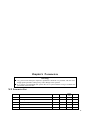
Chapter 5 Parameters
Warning
● Any person who attempts to adjust the parameters should be very familiar with the drive.
Inappropriate parameter settings may cause damage to the operator.
● It is strongly recommended that operate the servo system without saving as modifies the
parameters at the first time.
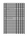
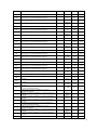
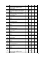
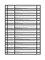
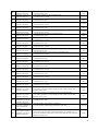
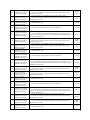
5.1
Parameter List
NO.
Parameter
M ode
Range
Default
value
0
Software edition
P,S,T
-
-
1
M otor type code
P,S,T
0~21
-
2
User constants protection code
P,S,T
0~32767
28977
3
Display mode
P,S,T
0~18
0
4
M otor control mode
P,S,T
0~6
5
Unit
24
5
M echanical brake delay time
P,S,T
1~1000
10
ms
6
Current turn off delay time
P,S,T
1~1000
10
ms
7
M echanical brake speed
P,S,T
0~6000
30
rpm
8
Anti-control of low-6-bit input terminal for PC interface
P,S,T
0~63
0
9
Anti-control of high-4-bit input terminal for PC interface
P,S,T
0~15
0
10
Anti-control of encoder input terminals
P,S,T
0~63
0
11
Force-ON of low-6-bit input terminal for PC interface
P,S,T
0~63
0
12
Force-ON of high-4-bit input terminal for PC interface
P,S,T
0~15
0
13
Anti-control of high-4-bit output ports for PC interface
P,S,T
0~15
0
14
Anti-control of low-3-bit output ports for PC interface
P,S,T
0~7
0
15
Gain of analog torque command input
T
10~300
100
16
The bias compensation of analog torque input
T
-30000~3
0000
0
17
Invert enable of analog torque input
T
0~1
0
18
Gain of analog speed command input
S
10~300
100
19
The bias compensation of analog speed input
S
-30000~3
0000
0
20
Invert enable of analog speed input
S
0~1
0
21
Low-pass bandwidth of analog speed input
S
0~1000
300
22
Torque overload alarm value
T
1~400
-
23
Torque overload testing time
T
1~32767
-
24
Internal brake resistor temperature alarm
P,S,T
0~1
1
25
Internal reverse rotation (CW) torque limit
P,S
1 ~ 400
300
26
Internal forward rotation (CCW) torque limit
P,S
1 ~ 400
300
27
External CW torque limit(NOT Support)
P,S
1 ~ 400
100
28
External CCW torque limit(NOT Support)
P,S
1 ~ 400
100
29
Speed limit during torque control
T
0~3000
2000
30
Speed loop gain
S
1~8000
-
31
Speed loop integral time constant
S
1~8000
-
32
Low-pass bandwidth of speed loop
S
1~1000
500
Hz
33
Low-pass filter bandwidth of torque command
T
50~1000
800
Hz
34
Time constant of linear speed acceleration
P,S,T
0~10000
0
0.1s
35
Time constant of linear speed deceleration
P,S,T
0~10000
0
0.1s
1500
rpm
1500
rpm
1500
rpm
mV
mV
Hz
ms
rpm
36
Internal speed 1
S
37
Internal speed 2(NOT Support)
S
38
Internal speed 3(NOT Support)
S
39
Internal speed 4(NOT Support)
S
-6000~60
00
-6000~60
00
-6000~60
00
-6000~60
00
40
Internal or external speed command selection
S
0~1
0
41
Speed setting in JOG mode (NOT Support)
0~3000
1500
rpm
42
Peak speed limitation
0~6000
3000
rpm
P,S,T
1500
25
43
Target speed
S,T
1~6000
1500
44
rpm
Position loop gain
P
1~10000
-
45
Difference coefficient ratio of position loop
P
0~8000
-
46
The cut-off frequency of position feed forward filter
P
1~300
100
47
Constant of position command filter
P
0~1000
0
48
Denominator of position gearbox
P
1~30000
20
49
Divider numerator of the 1nd postion command pulse
P
1~30000
20
50
Divider numerator of the 2nd postion command
pulse(NOT Support)
P
1~30000
20
51
Dynamic electronic gear enable(NOT Support)
P
0~1
0
52
Position command pulse input mode
P
0~2
0
53
Invert direction of position command pulse
P
0~1
0
54
Positioning completed range
P
0~30000
1
55
Range of position super-homodyne detection
P
1~30000
30000
56
Enable position error
P
0~1
1
57
Position pulse feedback ratio
P
0~3
0
58
Home position(NOT Support)
0~2
0
59
Homing speed(NOT Support)
1~6000
100
rpm
60
Homing acceleration/ deceleration speed(NOT Support)
1~1000
50
R/
(s*s)
61
High bit of home offset(NOT Support)
0
62
Low bit of home offset(NOT Support)
63
Demo or point-to-point mode(NOT Support)
-30000~3
0000
-9999~99
99
0~4
64
Torque value 1 in torque mode(NOT Support)
-400~400
10
65
Demo time 1 in torque mode(NOT Support)
0~3600
60
66
Torque value 2 in torque mode(NOT Support)
-200~200
-10
67
Demo time 2 in torque mode(NOT Support)
0~3600
60
68
Torque value 3 in torque mode(NOT Support)
-200~200
20
69
Demo time 3 in torque mode(NOT Support)
0~3600
60
70
Torque value 4 in torque mode(NOT Support)
-200~200
-20
71
Demo time 4 in torque mode(NOT Support)
0~3600
60
72
Torque value 5 in torque mode(NOT Support)
-200~200
30
73
Demo time 5 in torque mode(NOT Support)
0~3600
60
74
Torque value 6 in torque mode(NOT Support)
-200~200
-30
75
Demo time 6 in torque mode (NOT Support)
0~3600
60
76
Torque value 7 in torque mode(NOT Support)
-200~200
80
77
Demo time 7 in torque mode(NOT Support)
0~3600
60
78
Torque value 8 in torque mode(NOT Support)
-200~200
-80
79
Demo time 8 in torque mode(NOT Support)
0~3600
60
80
Torque value 9 in torque mode(NOT Support)
-200~200
100
81
Demo time 9 in torque mode(NOT Support)
0~3600
60
Hz
0
2
s
s
s
s
s
s
s
s
s
26
82
Torque value 10 in torque mode(NOT Support)
-200~200
-100
83
Demo time 10 in torque mode(NOT Support)
0~3600
60
s
84
Speed value 1 in speed mode(NOT Support)
-6000~60
00
10
rpm
85
Demo time 1 in speed mode(NOT Support)
0~3600
60
s
86
Speed value 2 in speed mode(NOT Support)
-6000~60
00
50
rpm
87
Demo time 2 in speed mode(NOT Support)
0~3600
60
s
88
Speed value 3 in speed mode(NOT Support)
-6000~60
00
250
rpm
89
Demo time 3 in speed mode(NOT Support)
0~3600
60
s
90
Speed value 4 in speed mode(NOT Support)
-6000~60
00
1250
rpm
91
Demo time 4 in speed mode(NOT Support)
0~3600
60
s
92
Speed value 5 in speed mode(NOT Support)
-6000~60
00
2500
rpm
93
Demo time 5 in speed mode(NOT Support)
0~3600
60
s
94
Speed value 6 in speed mode(NOT Support)
-6000~60
00
-10
rpm
95
Demo time 6 in speed mode(NOT Support)
0~3600
60
s
96
Speed value 7 in speed mode(NOT Support)
-6000~60
00
-50
rpm
97
Demo time 7 in speed mode(NOT Support)
0~3600
60
s
98
Speed value 8 in speed mode(NOT Support)
-6000~60
00
-250
rpm
99
Demo time 8 in speed mode(NOT Support)
0~3600
60
s
100
Speed value 9 in speed mode(NOT Support)
-6000~60
00
-1250
rpm
101
Demo time 9 in speed mode(NOT Support)
0~3600
60
s
-2500
rpm
60
s
102
Speed value 10 in speed mode(NOT Support)
-6000~60
00
103
Demo time 10 in speed mode(NOT Support)
0~3600
104
105
106
107
108
109
110
111
112
113
114
115
116
High bit of position command 1 in position mode(NOT
Support)
Low bit of position command 1 in position mode(NOT
Support)
Speed of position command 1 in position mode(NOT
Support)
Acceleration/deceleration of position command 1 in
position mode(NOT Support)
Peak torque of position command 1 in position
mode(NOT Support)
High bit of position command 2 in position mode(NOT
Support)
Low bit of position command 2 in position mode(NOT
Support)
Speed of position command 2 in position mode(NOT
Support)
Acceleration / deceleration of position command 2 in
position mode(NOT Support)
Peak torque of position command 2 in position
mode(NOT Support)
High bit of position command 3 in position mode(NOT
Support)
Low bit of position command 3 in position mode(NOT
Support)
Speed of position command 3 in position mode(NOT
-30000~3
0000
-9999~99
99
50
0
0~6000
2000
1~1000
25
R/
(s*s)
0~400
125
N.M
-30000~3
0000
-9999~99
99
10
0
0~6000
2000
1~1000
25
0~400
125
-30000~3
0000
-9999~99
99
0~6000
N.M
90
0
2000
27
Support)
117
118
119
120
121
122
123
124
125
126
127
128
129
130
131
132
133
134
135
136
137
138
139
140
141
142
143
144
145
146
147
148
Acceleration / deceleration of position command 3 in
position mode(NOT Support)
Peak torque of position command 3 in position
mode(NOT Support)
High bit of position command 4 in position mode(NOT
Support)
Low bit of position command 4 in position mode(NOT
Support)
Speed of position command 4 in position mode(NOT
Support)
Acceleration / deceleration of position command 4 in
position mode(NOT Support)
Peak torque of position command 4 in position
mode(NOT Support)
High bit of position command 5 in position mode(NOT
Support)
Low bit of position command 5 in position mode(NOT
Support)
Speed of position command 5 in position mode(NOT
Support)
Acceleration / deceleration of position command 5 in
position mode(NOT Support)
Peak torque of position command 5 in position
mode(NOT Support)
High bit of position command 6 in position mode(NOT
Support)
Low bit of position command 6 in position mode(NOT
Support)
Speed of position command 6 in position mode(NOT
Support)
Acceleration / deceleration of position command 6 in
position mode(NOT Support)
Peak torque of position command 6 in position
mode(NOT Support)
High bit of position command 7 in position mode(NOT
Support)
Low bit of position command 7 in position mode(NOT
Support)
Speed of position command 7 in position mode(NOT
Support)
Acceleration / deceleration of position command 7 in
position mode(NOT Support)
Peak torque of position command 7 in position
mode(NOT Support)
High bit of position command 8 in position mode(NOT
Support)
Low bit of position command 8 in position mode(NOT
Support)
Speed of position command 8 in position mode(NOT
Support)
Acceleration / deceleration of position command 8 in
position mode (NOT Support)
Peak torque of position command 8 in position
mode(NOT Support)
High bit of position command 9 in position mode(NOT
Support)
Low bit of position command 9 in position mode(NOT
Support)
Speed of position command 9 in position mode(NOT
Support)
Acceleration / deceleration of position command 9 in
position mode(NOT Support)
Peak torque of position command 9 in position
mode(NOT Support)
1~1000
25
0~400
125
-30000~3
0000
-9999~99
99
20
0~6000
2000
1~1000
25
0~400
125
-30000~3
0000
-9999~99
99
0
0
2000
1~1000
25
0~400
125
0
2000
1~1000
25
0~400
125
0
2000
1~1000
25
0~400
125
N.M
30
0
0~6000
2000
1~1000
25
0~400
125
-30000~3
0000
-9999~99
99
N.M
50
0~6000
-30000~3
0000
-9999~99
99
N.M
80
0~6000
-30000~3
0000
-9999~99
99
N.M
50
0~6000
-30000~3
0000
-9999~99
99
N.M
N.M
10
0
0~6000
2000
1~1000
25
0~400
125
N.M
28
149
150
151
152
153
154
155
156
157
158
159
160
161
162
163
164
165
166
167
168
169
170
171
172
173
174
175
176
177
178
179
180
181
High bit of position command 10 in position mode(NOT
Support)
Low bit of position command 10 in position mode(NOT
Support)
Speed of position command 10 in position mode(NOT
Support)
Acceleration / deceleration of position command 10 in
position mode(NOT Support)
Peak torque of position command 10 in position
mode(NOT Support)
High bit of position command 11 in position mode(NOT
Support)
Low bit of position command 11 in position mode(NOT
Support)
Speed of position command 11 in position mode(NOT
Support)
Acceleration / deceleration of position command 11 in
position mode(NOT Support)
Peak torque of position command 11 in position
mode(NOT Support)
High bit of position command 12 in position mode(NOT
Support)
Low bit of position command 12 in position mode(NOT
Support)
Speed of position command 12 in position mode(NOT
Support)
Acceleration / deceleration of position command 12 in
position mode(NOT Support)
Peak torque of position command 12 in position
mode(NOT Support)
High bit of position command 13 in position mode(NOT
Support)
Low bit of position command 13 in position mode(NOT
Support)
Speed of position command 13 in position mode(NOT
Support)
Acceleration / deceleration of position command 13 in
position mode(NOT Support)
Peak torque of position command 13 in position
mode(NOT Support)
High bit of position command 14 in position mode(NOT
Support)
Low bit of position command 14 in position mode(NOT
Support)
Speed of position command 14 in position mode(NOT
Support)
Acceleration / deceleration of position command 14 in
position mode(NOT Support)
Peak torque of position command 14 in position
mode(NOT Support)
High bit of position command 15 in position mode(NOT
Support)
Low bit of position command 15 in position mode(NOT
Support)
Speed of position command 15 in position mode(NOT
Support)
Acceleration / deceleration of position command 15 in
position mode(NOT Support)
Peak torque of position command 15 in position
mode(NOT Support)
High bit of position command 16 in position mode(NOT
Support)
Low bit of position command 16 in position mode(NOT
Support)
Speed of position command 16 in position mode(NOT
-30000~3
0000
-9999~99
99
80
0
0~6000
2000
1~1000
25
0~400
125
-30000~3
0000
-9999~99
99
50
0
0~6000
2000
1~1000
25
0~400
125
-30000~3
0000
-9999~99
99
0
2000
1~1000
25
0~400
125
0
2000
1~1000
25
0~400
125
N.M
50
0
0~6000
2000
1~1000
25
0~400
125
-30000~3
0000
-9999~99
99
N.M
30
0~6000
-30000~3
0000
-9999~99
99
N.M
60
0~6000
-30000~3
0000
-9999~99
99
N.M
N.M
100
0
0~6000
2000
1~1000
25
0~400
125
-30000~3
0000
-9999~99
99
50
0~6000
2000
N.M
0
29
Support)
182
183
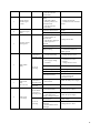
5.2
NO
0
1
Acceleration / deceleration of position command 16 in
position mode(NOT Support)
Peak torque of position command 16 in position
mode(NOT Support)
1~1000
25
0~400
125
N.M
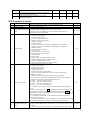
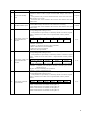
Parameter Contents
Parameter
Firmware edition
M otor type code
2
User constants protection
code
3
Display mode
4
M otor control mode
5
M echanical brake delay
time
Parameter description
Range
Firmware edition of servo drive. Can't be modified by users.
-
The type code of motors;
0~21
It is used to prevent the parameters from being changed accidentally. The
parameters can be modified as the value is set to 28977.
0~32767
We suggest users to change it into a value other than 28977 after the
parameters having been adjusted.
Select the information display ing on the panel:
0: M otor's current torque;
1: M otor's current speed;
2: Low-5-bit of current position;
3: High-5-bit of current position;
4: Torque command;
5: Speed command;
6: Low-5-bit of position command(command pulse accumulation);
7: High-5-bit of position command(command pulse accumulation);
8: M otor's current;
0~18
9: Counter of encoder output;
10: Linear speed;
11: Low-5-bit of position deviation;
12: High-5-bit of position deviation;
13: Control mode;
14: Alarm code;
15: States of low part input terminals in CN2;
16: States of high part input terminals in CN2;
17: State of output terminals in CN2;
18: State of the optical encoder in input terminals;
①Select the control mode of servo drive:
0: Torque control mode;
1: Speed control mode;
2: Position control mode;
3: JOG control mode;
4: Speed trial operation control mode;
5: Auto-correction mode(used to correct ports and internal control
parameter for motor);
6: Demo mode (Torque/Speed/Position)/point to point mode;
②In speed control mode, speed command transmits from input terminals
(PN40).Set SC1 and SC2 to choose the internal speed:
SC1 OFF, SC2 OFF: Internal speed 1;
SC1 OFF, SC2 ON : Internal speed 2;
0~6
SC1 ON , SC2 OFF: Internal speed 3
SC1 ON , SC2 ON : Internal speed 4;
③In position control mode, position command transmits from pulse input
ports.
④In JOG control mode, press Up continuously, the motor is running at JOG
speed, release the key, motor stops and keeps zero-speed; Press Down
continuously, the motor is running in the reverse direction, release the key, motor
stops and keeps zero-speed;
⑤In speed trial control mode, speed command is input from keyboard to
test the drive and motor;
⑥In auto-correction mode, users can adjust the zero-compensation for analog,
torque and speed input port as well as the internal control parameters.
①Set the delay time from the moment that mechanical brake available
(output terminals BRK changes from OFF to ON) to the time motor current 1~1000m
is cut off.
s
②This parameter should be bigger than mechanical braking delay time to
30
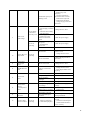
6
Current turn off delay
time
7
M echanical brake speed
8
Anti-control of low-6-bit
input terminal for PC
interface
9
Anti-control of high-4-bit
input terminal for PC
interface
10
Anti-control of encoder
input terminals
avoid motor for micro-displacement or falling.
①Set the delay time from the moment the motor current is cut off to the time
mechanical brake available (output terminals BRK changes from OFF to
ON).
②This parameter will protect the mechanical brake as the motor runs from a
high speed to a low speed.
③The actual time is the minimum value between PN5 and the time speed
falls to PN6.
①Set the motor speed ensuring that mechanical brake is active (output
terminal BRK changes from OFF to ON) when motor is running.
②The actual time is the minimum value between PN5 and the time speed
falls to PN6.
①Inverting enable of input terminals. Invert the input signal when the
corresponding enable setting is active.
②This parameter is expressed by a 6-bit binary number. 0 stands for original
state, 1 stands for invert state. Here’s a input terminal of binary number
below:
5
ServoEn
4
3
2
1
0
AlarmCl CCWDi
CWDis
CCWTLt CWTLt
r
s
d
d
ServoEn: Servo enable;
AlarmClr: Alarm clear;
CCWDis: CCW(counter-clockwise) drive forbidden;
CWDis: CW(clockwise) drive forbidden;
CCWTLtd: CCW torque limited;
CWTLtd: CW torque limited;
①Inverting enable of input terminals. Invert the input signal when the
corresponding enable setting is active.
②This parameter is expressed by a 4-bit binary number. 0 stands for original
state, 1 stands for invert state. Here’s a input terminal of binary number
below:
3
2
1
0
CLE/SC1/ZEROSP
INH/SC2
SignInv
PulseInv
D
CLE/SC1/ZEROSPD: Offset counter clear / Speed selector 1 / Zero clamp;
INH/SC2: Command pulse forbidden(dynamic electronic gear switch)
/Speed selector 2;
SignInv: Position command pulse symbol bit;
PulseInv: Position command pulse bit;
①Inverting enable of input terminals. Invert the input signal when the
corresponding enable setting is active.
②This parameter is expressed by a 6-bit binary number. 0 stands for original
state, 1 stands for invert state. Here’s a input terminal of binary number
below::
5
4
3
2
1
PhaseU
PhaseV
PhaseW
PhaseA
PhaseB
Phase U: Photoelectric incremental encoder phase U;
Phase V: Photoelectric incremental encoder phase V;
Phase W:Photoelectric incremental encoder phase W;
Phase A: Photoelectric incremental encoder phase A;
Phase B: Photoelectric incremental encoder phase B;
Phase Z: Photoelectric incremental encoder phase Z;
0
PhaseZ
1~1000m
s
0~6000
0~63
0~15
0~63
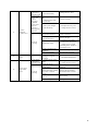
31
①Force the input signal active when the corresponding enable setting is
active;
②This parameter is expressed by a 6-bit binary number. 0 stands for the
unforce-ON for input terminal, 1 stands for the force-ON for input terminal.
Here’s a input terminal of binary number below:
11
Force-ON of low-6-bit
input terminal for PC
interface
5
ServoEn
4
3
2
1
AlarmCl CCWDi
CWDis
CCWTLt
r
s
d
ServoEn: Servo enable;
AlarmClr: Alarm clear;
CCWDis: CCW(counter-clockwise) drive forbidden;
CWDis: CW(counter-clockwise) drive forbidden;
CCWTLtd: CCW torque limited;
CWTLtd : CW torque limited;
0
CWTLtd
0~63
①External connection to control ON / OFF,for the terminal of force-ON, the
drive can set ON automatically at internal without external connection.
②This parameter is expressed by a 4-bit binary number. 0 stands for the
unforce-ON for input terminal, 1 stands for the force-ON for input terminal.
Here’s a input terminal of binary number below:
12
Force-ON of high-4-bit
input terminal for PC
interface
13
Anti-control of high-4-bit
output ports for PC
interface
14
Anti-control of low-3-bit
output ports for PC
interface
15
Gain of analog torque
command input
16
The bias compensation of
analog torque input
17
Invert enable of analog
torque input
3
2
1
0
CLE/SC1/ZEROS
INH/SC2
SignInv
PulseInv
PD
CLE/SC1/ZEROSPD: Offset counter clear / Speed selector 1 / Zero clamp;
INH/SC2: Command pulse forbidden(dynamic electronic gear switch)
/Speed selector 2;
SignInv: Position command pulse symbol bit;
PulseInv: Position command pulse bit;
①Inverting enable of output terminals. For the anti-control terminal, turn-on
and cut-off definition are opposited from standard definition.
②This parameter is expressed by a 4-bit binary number. 0 stands for the no
anti-control output terminal, 1 stands for the anti-control output terminal.
Here’s a input terminal of binary number below:
3
2
1
0
SRDY
ALM
COIN
BRK
SRDY: Servo ready;
ALM : Servo alarm;
COIN: Positioning complete / Reach speed
BRK: M echanical brake release.
①Inverting enable of output terminals. For the anti-control terminal, turn-on
and cut-off definition are opposite from standard definition.
②This parameter is expressed by a 3-bit binary number. 0 stands for the no
anti-control output terminal, 1 stands for the anti-control output terminal.
Here’s a input terminal of binary number below:
0~15
0~15
0~7
2
1
0
PhaseA_O
PhaseB_O
PhaseZ_O
PhaseA_O:Phase A output of rotor position;
PhaseB_O:Phase B output of rotor position;
PhaseZ_O: Phase Z output of rotor position.
①Set proportion relationship between analog torque input voltage and actual
motor torque;
②Parameter unit is 100%/0.1V;
③The default value is 100, corresponding to 100%/10V (Input 10V to
generate 100% of nominal torque).
①The zero-bias compensation for the analog torque input;
②Parameter unit is mV.
①Set the parameter to 0, as the analog torque command is positive, motor
runs in reverse rotation (CW) direction,;
②Set the parameter to 1, as the analog torque command is positive, motor
runs forward rotation (CCW) direction.
10~300
-30000~
30000m
V
0~1
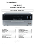
32
18
Gain of analog speed
command input
19
The bias compensation of
analog speed input
20
Invert enable of analog
speed input
21
Low-pass bandwidth of
analog speed input
22
Torque overload alarm
value
23
Torque overload testing
time
24
Internal brake resistor
temperature alarm
25
Internal reverse rotation
(CW) torque limit
26
Internal forward rotation
(CCW) torque limit
27
External CW torque
limit(NOT Support)
28
External CCW torque
limit(NOT Support)
29
Speed limit during torque
control
30
Speed loop gain
①Set proportion relationship between the input voltage of analog speed and
actual motor speed;
②Parameter unit is 3000rpm/0.1V;
③The default value is 100, corresponding to 3000rpm/10V.
①The zero-bias compensation for the analog speed input;
②Parameter unit is mV.
①Set the parameter to 0, as the analog speed command is positive, motor
runs in reverse rotation (CW) direction,;
②Set the parameter to 1, as the analog speed command is positive, motor
runs forward rotation (CCW) direction.
① Low-pass filter of the analog speed input.
②The greater the value is, it would bring faster response of analog speed
input and more signal noise; The smaller the value is, it would bring slower
response of analog speed input and less signal noise.
①Torque overload value. The value is the percentage of nominal torque
which effects both direction(CW/CCW);
②As the motor torque > PN22 and lasting time > PN23, the drive will alarm
Err-18 the motor will stop.
①Parameter unit is ms;
②As the motor torque > PN22 and lasting time > PN23, the drive will alarm
Err-18, the motor will stop.
①Set 1, internal brake resistor temperature alarm enabled;
②Set 0, internal brake resistor temperature alarm disabled.
①Used to limit the torque in the reverse rotation driving mode;
②Parameter value is the percentage of nominal torque, for example, the
value of 200 if it is set to 2 times of the nominal torque;
③This limitation is valid all time;
④Actual torque limit equals to the allowed peak overload on the condition
that the setting value exceed the allowed peak overload.
①Used to limit the torque in the forward rotation driving mode
②Parameter value is the percentage of nominal torque, for example, the
value of 200 if it is set to 2 times of the nominal torque;
③This limitation is valid all time;
④Actual torque limit equals to the allowed peak overload on the condition
that the setting value exceed the allowed peak overload.
①Set the external torque limit for motor CW;
②Parameter value is the percentage of nominal torque, for example, the
value of 100 if it is set to 1 time of the nominal torque;
③The limitation is valid only when the CW torque limit input terminal ON;
④The actual torque limit is the minimum value among allowed peak
overload,CW internal torque limit and CW external torque limit as the
limitation is valid.
①Set the external torque limit for motor CCW;
②Parameter value is the percentage of nominal torque, for example, the
value of 100 if it is set to 1 time of the nominal torque;
③The limitation is valid only when the CCW torque limit input terminal ON;
④The actual torque limit is the minimum value among allowed peak
overload,CCW internal torque limit and CCW external torque limit as the
limitation is valid.
①Limit the maximum speed in torque control mode, parameter unit is rpm;
②Avoid overspeed when the motor unloaded.
①Set the speed loop proportional gain;
②The larger the value is, the greater the stiffness would be. The value is
determined by the type of servo and the load condition. In general, larger load
inertia needs larger value.
③If there is no oscillation, the higher the value is the better the servo system
performs.
10~300
-30000~
30000m
V
0~1
1~1000H
z
1~400
1~32767
ms
0~1
1~400
1~400
1~400
1~400
0~3000
1~8000
33
31
Speed loop integral time
constant
32
Low-pass bandwidth of
speed loop
33
Low-pass filter
bandwidth of torque
command
34
Time constant of linear
speed acceleration
35
Time constant of linear
speed deceleration
36
Internal speed 1
37
Internal speed 2(NOT
Support)
38
Internal speed 3(NOT
Support)
39
Internal speed 4(NOT
Support)
40
Internal or external speed
command selection
41
Speed setting in JOG
mode (NOT Support)
42
Peak speed limitation
43
Target speed
44
Position loop gain
45
Difference coefficient
ratio of position loop
46
The cut-off frequency of
①Set the speed loop integral time constant;
②The smaller the value, the greater the stiffness. The value is determined by
the type of servo and the load condition. In general, larger load inertia needs
larger value.
③Set the parameter as small as possible without oscillation.
①Set the characteristics of speed detection filter;
②Normally, smaller value results in slower and smoother speed response.
Too small value may cause system oscillation.
①Set the characteristics of speed detection filter;
②Normally, smaller value results in slower and smoother speed response.
But too much small value may cause system oscillation.
①The value means motor accelerates from 0 to 1000 r/min, the unit ×0.01s;
②Characteristics of acceleration and deceleration is linear; the range of valid
value from 1 to 10000;
③Affective in speed control mode only;
④If the drive works in position control mode or the external position loop,
the parameter should be set to 0.
①The value means motor decelerates from 1000 to 0 r/min, the unit ×0.01s;
②Characteristics of acceleration and deceleration is linear; the range of valid
value from 1 to 10000;
③Affective in speed control mode only;
④If the drive works in position control mode or the external position loop,
the parameter should be set to 0.
①Set the first internal speed;
②In speed control mode, select the first internal speed as the speed
command when SC1 OFF, SC2 OFF.
①Set the first internal speed;
②In speed control mode, select the second internal speed as the speed
command when SC1 OFF, SC2 ON.
①Set the first internal speed;
②In speed control mode, select the third internal speed as the speed
command when SC1 ON, SC2 OFF.
①Set the first internal speed;
②In speed control mode, select the fourth internal speed as the speed
command when SC1 ON, SC2 ON.
①Set the parameter to 0, select the internal speed control mode;
②Set the parameter to 1, select the external speed control mode.
Set the operation speed in JOG control mode.
①Set the maximum speed limitation of servo motor;
②The function is effective in both CCW and CW direction;
③The selected speed equals to actual peak speed if it is smaller than the
value.
①Position target speed, the unit is r/min;
②In non-position control mode, if the motor speed exceeds the set value,
then COIN ON, otherwise COIN OFF;
③This parameter is not effective in position control mode,;
④CCW and CW directions are both effective;
⑤The comparator has hysteresis characteristics.
1~8000
1~1000H
z
50~1000
Hz
0~10000
0~10000
-6000~6
000
-6000~6
000
-6000~6
000
-6000~6
000
0~1
0~3000
0~6000
1~6000
①Set the speed loop proportional gain;
②Higher gain results in greater mechanical stiffness and less position
1~10000
tracking error. Too large value may cause overshoot or oscillation.
③The value is determined by the type and the load of servo drive.
①Set the difference gain of position loop ;
② Higher gain results in greater mechanical stiffness and less position tracking
0~8000
error. Too big value may cause overshoot or oscillation;
③This parameter is usually set to zero unless very fast response is required.
①Set the low-pass filter cut-off frequency of position loop feed forward.
1~300
34
position feed forward
filter
47
Constant of position
command filter
48
Denominator of position
gearbox
the unit is Hz;
②The filter is used to increase the stability of compound position control.
①Smoothen filter for the command pulse with the accelerate of index form,
the value stands for time constant. The unit is ms;
②Filter would not lose input pulse but may lead to delay ;
③The filter works in the follow conditions:
0~1000
● Host controller has not acceleration and deceleration function;
● Larger electronic gear ratio (>10);
● Lower command frequency;
● M otor running with jumps or other unstable conditions;
④Filter is inactive as set to 0.
①Set the denominator of sub-octave for position command pulse (electric
gear);
②In the position control mode, conveniently match with any pulse source by
setting parameters PN48 and PN49 to meet the ideal control resolution
(angle/pulse);
③P×G=N×C×4
P : Input command pulse number;
G: Electronic gear ratio;
N: The revolving circle of the motor;
1~30000
C: The photoelectric encoder C/T, this system is C=2500;
④For example, the motor runs one circle when the input command pulse is 6000,
G
N C 4 1 2500 4 5
P
6000
3
So please set PN49=5, PN48=3
⑤Recommendatory range of electronic gear ratio:
1/50≤G≤50
49
Divider numerator of the
first position command
pulse
50
Divider numerator of the
second position
command pulse(NOT
Support)
51
Dynamic electronic gear
enable(NOT Support)
52
Position command pulse
input mode
53
Invert direction of
position command pulse
54
Positioning completed
range
55
Range of position
super-homodyne
detection
①Set the first position command pulse sub-octave (electronic gear);
②Set parameter PN51 to 1 as using the dynamic electronic gear, meanwhile
the function of input terminal INH (command pulse forbidden) translates into
control terminal of electronic gear switching input.
①Set the second position command pulse sub-octave (electronic gear);
②Set parameter PN51 to 1 as using the dynamic electronic gear, meanwhile
the function of input terminal INH (command pulse forbidden) translates into
control terminal of electronic gear switching input.
①Set to 0, dynamic electronic gearbox is inactive.
②Set to 1, dynamic electronic gearbox is active.
③When dynamic electronic gearbox is active, the input terminal INH(Inhibit
Position instruction) functions as a switch to select electronic gear ratio
generated by the first or the second numerator;
④When dynamic electronic gearbox is active, if INH terminal is inactive, the
active G=PN50/PN48; If INH terminal is active, the active G=PN49/PN48;
By controlling INH terminal, PLC cant switch the electronic gear ratio.
①Set the input form of position command pulse;
②Three position command types are supported as following:
0: Pulse + symbol;
1: CCW pulse / CW pulse;
2: Two-phase orthogonal pulse input;
③CCW is defined as positive direction on the condition that it rotates with
anti-clockwise direction from the axial view.
Select condition:
0: Normal;
1: Reverse the direction of position command pulse.
①Position range indicates the motor has reached the target location;
②In position control mode or point to point mode, if the position error drops
in the target position range, the output terminal COIN turns active, otherwise
COIN remains inactive.
①Set the detection range for position tolerance alarm;
②The drive will issue position tolerance alarm when the position offset
counter value exceeds the selected value×100 in position control mode.
1~30000
1~30000
0~1
0~2
0~1
0~30000
1~30000
35
56
Enable position error
57
Position pulse feedback
ratio
58
Home position(NOT
Support)
59
Homing speed(NOT
Support)
60
Homing acceleration/
deceleration speed(NOT
Support)
61
High bit of home
offset(NOT Support)
62
Low bit of home
offset(NOT Support)
63
Demo or point-to-point
mode(NOT Support)
Select condition:
0: position tolerance alarm detection enabled;
1: position tolerance alarm detection disabled and position tolerance error
detection is stopped.
①The feedback ratio of position pulse determines the ratio of the internal
and ouput position pulse:
②[4:0] : Feedback setting: B, Ratio=A/B.
③[9:5] : Feedback setting: A, Ratio=A/B.
④[15:10] : Reserved.
⑤Normal setting : 1:1 => 33 (00001_00001)
1:2 => 34 (00001_00010)
1:4 => 36 (00001_00100)
1:5 => 37 (00001_00101)
1:10 => 42 (00001_01010)
⑥(Ratio x Encoder pulse number) should be a integer.
The mode of capture Home signal. Three homing methods are supported.
①Set PN58 to 0, the servo seeks home position with CW limit switch; Servo
would move in CW direction until meets CW limit switch, then turns back
and treats the first Index signal as home position;
②Set PN58 to 1, the servo seeks home position with CCW limit switch.
Servo would move in CCW direction until meets CCW limit switch, then
turns back and treats the first Index signal as home position;
③Set PN58 to 2, the current position is set as home position.
①The maximum running speed for motor in the process of seeking home
position;
②The speed value is effective in both CCW and CW direction. The unit is
r/min;
③Caution: Too fast homing speed may cause mechanical damage at limit
switch.
①The acceleration and deceleration value in the process of seeking home
position;
②The value is effective in both CCW and CW direction. The unit is r/(s*s);
③Caution: Too weak acceleration and deceleration speed may cause
mechanical damage at limit switch.
①A 16-bit space is narrow for a 32-bit. So the home offset is stored to
high-bit and low-bit;
②The actual origin offset = PN61×10000+PN62.
①A 16-bit space is narrow for a 32-bit. So the home offset is stored to
high-bit and low-bit;
②The actual origin offset = PN61×10000+PN62.
①Demo mode or point-to-point mode;
②Set to 0, the drive will work in torque demo mode. From step 1 to 10,
servo runs each step one by one and loops forever. In every step torque value
and lasting time can be set independently.
③Set to 1, the drive will work in speed demo mode. From step 1 to 10, servo
runs each step one by one and loops forever. In every step torque value and
lasting time can be set independently.
④Set to 2, the drive will work in position demo mode, From step 1 to 10,
servo runs each step one by one and loops forever. In every step position,
speed, acceleration and maximum torque value can be set independently.
⑤Set to 3, the drive will work in absolute value point-to-point mode.
⑥Set to 4, the drive will work in increment point-to-point mode..
⑦There are four parameters can be selected independently: Position, Speed,
Acceleration and M aximum Torque in point-to-point mode. The position
index is determined by input terminals { CCWTLtd, CWTLtd, SC1, SC2 }:
If CCWTLtd=0, CWTLtd=0,SC1=0, SC2=0, then select position 1;
If CCWTLtd=0, CWTLtd=0,SC1=0, SC2=1, then select position 2;
If CCWTLtd=0, CWTLtd=0, SC1=1, SC2=0, then select position 3;
......
If CCWTLtd=1, CWTLtd=0,SC1=1, SC2=1, then select position 12;
......
If CCWTLtd=1, CWTLtd=1, SC1=1, SC2=0 then select position 15;
If CCWTLtd=1, CWTLtd=1, SC1=1, SC2=1, then select position 16;
0~1
1~1023
0~3
1~6000
1~1000
-30000~
30000
-9999~9
999
0~3
36
64
Torque value 1 in torque
mode(NOT Support)
65
Demo time 1 in torque
mode(NOT Support)
66
Torque value 2 in torque
mode(NOT Support)
67
Demo time 2 in torque
mode(NOT Support)
68
Torque value 3 in torque
mode(NOT Support)
69
Demo time 3 in torque
mode(NOT Support)
70
Torque value 4 in torque
mode(NOT Support)
71
Demo time 4 in torque
mode(NOT Support)
72
Torque value 5 in torque
mode(NOT Support)
73
Demo time 5 in torque
mode(NOT Support)
74
Torque value 6 in torque
mode(NOT Support)
75
Demo time 6 in torque
mode (NOT Support)
76
Torque value 7 in torque
mode(NOT Support)
77
Demo time 7 in torque
mode(NOT Support)
78
Torque value 8 in torque
mode(NOT Support)
79
Demo time 8 in torque
mode(NOT Support)
80
Torque value 9 in torque
mode(NOT Support)
81
Demo time 9 in torque
mode(NOT Support)
82
Torque value 10 in
torque mode(NOT
Support)
83
Demo time 10 in torque
mode(NOT Support)
①Set the first torque value in torque demo mode;
②Parameter value is the percentage of the nominal torque, for example, if
you want to set maximum torque to the 1 times of the nominal torque, the
parameter is 100.
①Set the first duration in torque demo mode.
②Parameter unit is second.
①Set the second torque value in torque demo mode;
②Parameter value is the percentage of the nominal torque, for example, if
you want to set maximum torque to the 1 times of the nominal torque, the
parameter is 100.
①Set the second duration in torque demo mode.
②Parameter unit is second.
①Set the third torque value in torque demo mode;
②Parameter value is the percentage of the nominal torque, for example, if
you want to set maximum torque to the 1 times of the nominal torque, the
parameter is 100.
①Set the third duration in torque demo mode.
②Parameter unit is second.
①Set the fourth torque value in torque demo mode;
②Parameter value is the percentage of the nominal torque, for example, if
you want to set maximum torque to the 1 times of the nominal torque, the
parameter is 100.
①Set the fourth duration in torque demo mode.
②Parameter unit is second.
①Set the fifth torque value in torque demo mode;
②Parameter value is the percentage of the nominal torque, for example, if
you want to set maximum torque to the 1 times of the nominal torque, the
parameter is 100.
①Set the fifth duration in torque demo mode.
②Parameter unit is second.
①Set the sixth torque value in torque demo mode;
②Parameter value is the percentage of the nominal torque, for example, if
you want to set maximum torque to the 1 times of the nominal torque, the
parameter is 100.
①Set the sixth duration in torque demo mode.
②Parameter unit is second.
①Set the seventh torque value in torque demo mode;
②Parameter value is the percentage of the nominal torque, for example, if
you want to set maximum torque to the 1 times of the nominal torque, the
parameter is 100.
①Set the seventh duration in torque demo mode.
②Parameter unit is second.
①Set the seventh torque value in torque demo mode;
②Parameter value is the percentage of the nominal torque, for example, if
you want to set maximum torque to the 1 times of the nominal torque, the
parameter is 100.
①Set the eighth duration in torque demo mode.
②Parameter unit is second.
①Set the ninth torque value in torque demo mode;
②Parameter value is the percentage of the nominal torque, for example, if
you want to set maximum torque to the 1 times of the nominal torque, the
parameter is 100.
①Set the ninth duration in torque demo mode.
②Parameter unit is second.
①Set the tenth torque value in torque demo mode;
②Parameter value is the percentage of the nominal torque, for example, if
you want to set maximum torque to the 1 times of the nominal torque, the
parameter is 100.
①Set the tenth duration in torque demo mode.
②Parameter unit is second.
-400~40
0
0~3600
-200~20
0
0~3600
-200~20
0
0~3600
-200~20
0
0~3600
-200~20
0
0~3600
-200~20
0
0~3600
-200~20
0
0~3600
-200~20
0
0~3600
-200~20
0
0~3600
-200~20
0
0~3600
37
84
Speed value 1 in speed
mode(NOT Support)
85
Demo time 1 in speed
mode(NOT Support)
86
Speed value 2 in speed
mode(NOT Support)
87
88
89
90
Demo time 2 in speed
mode(NOT Support)
Speed value 3 in speed
mode(NOT Support)
Demo time 3 in speed
mode(NOT Support)
Speed value 4 in speed
mode(NOT Support)
91
Demo time 4 in speed
mode(NOT Support)
92
Speed value 5 in speed
mode(NOT Support)
93
Demo time 5 in speed
mode(NOT Support)
94
Speed value 6 in speed
mode(NOT Support)
95
Demo time 6 in speed
mode(NOT Support)
96
Speed value 7 in speed
mode(NOT Support)
97
Demo time 7 in speed
mode(NOT Support)
98
Speed value 8 in speed
mode(NOT Support)
99
Demo time 8 in speed
mode(NOT Support)
100
Speed value 9 in speed
mode(NOT Support)
101
Demo time 9 in speed
mode(NOT Support)
102
Speed value 10 in speed
mode(NOT Support)
103
Demo time 10 in speed
mode(NOT Support)
104
High bit of position
command 1 in position
mode(NOT Support)
105
106
107
108
Low bit of position
command 1 in position
mode(NOT Support)
Speed of position
command 1 in position
mode(NOT Support)
Acceleration/deceleration
of position command 1 in
position mode(NOT
Support)
Peak torque of position
command 1 in position
mode(NOT Support)
①Set the first speed value in the speed demo mode;
②Parameter unit is rpm.
①Set the first duration in the speed demo mode;
②Parameter unit is second.
①Set the second speed value in speed demo mode;
②Parameter unit is rpm..
①Set the second duration of speed value in speed demo mode;
②Parameter unit is second.
①Set the third speed value in speed demo mode;
②Parameter unit is rpm.
①Set the third duration of speed value in speed demo mode;
②Parameter unit is second.
①Set the fourth speed value in speed demo mode;
②Parameter unit is rpm.
①Set the fourth duration of speed value in speed demo mode
②Parameter unit is second.
①Set the fifth speed value in speed demo mode;
②Parameter unit is rpm.
①Set the fifth duration of speed value in speed demo mode;
②Parameter unit is second.
①Set the sixth speed value in speed demo mode;
②Parameter unit is rpm.
①Set the sixth duration of speed value in speed demo mode;
②Parameter unit is second.
①Set the seventh speed value in speed demo mode;
②Parameter unit is rpm.
①Set the seventh duration of speed value in speed demo mode;
②Parameter unit is second.
①Set the eighth speed value in speed demo mode;
②Parameter unit is rpm.
①Set the ninth duration of speed value in speed demo mode;
②Parameter unit is second.
①Set the ninth speed value in speed demo mode;
②Parameter unit is rpm.
①Set the ninth duration of speed value in speed demo mode;
②Parameter unit is second.
①Set the tenth speed value in speed demo mode;
②Parameter unit is rpm.
①Set the tenth duration of speed value in speed demo mode;
②Parameter unit is second.
①Set the first high bit command value in position demo mode;
②The value of position 1 equals to high-bit value×10000+low-bit value.
Parameter unit is pulse.
①Set up the first low bit command value in position demo mode.
②The value of position 1 equals to high-bit value×10000+low-bit value.
Parameter unit is pulse.
-6000~6
000
0~3600
-6000~6
000
0~3600
-6000~6
000
0~3600
-6000~6
000
0~3600
-6000~6
000
0~3600
-6000~6
000
0~3600
-6000~6
000
0~3600
-6000~6
000
0~3600
-6000~6
000
0~3600
-6000~6
000
0~3600
-30000~
30000
-9999~9
999
①The speed value of position 1;
②Parameter unit is rpm.
0~6000
①The acceleration / deceleration in position 1;
②The acceleration and deceleration share the same value.
1~1000
①The maximum torque in position 1;
②The value is the percentage of the nominal torque, for example, if you
want to set maximum torque value as same as the nominal torque value, the
parameter would be 100.
0~400
38
109
High bit of position
command 2 in position
mode(NOT Support)
①Set the second high bit command value in position demo mode;
②The value of position 2 equals to high-bit value×10000+low-bit value.
Parameter unit is pulse.
-30000~
30000
110
Low bit of position
command 2 in position
mode(NOT Support)
①Set the second low bit command value in position demo mode;
②The value of position 2 equals to high-bit value×10000+low-bit value.
Parameter unit is pulse.
-9999~9
999
Speed of position
command 2 in position
mode(NOT Support)
Acceleration /
deceleration of position
command 2 in position
mode(NOT Support)
①The speed value of position 2;
②Parameter unit is rpm.
0~6000
①The acceleration / deceleration in position 2;
②The acceleration and deceleration share the same value..
1~1000
111
112
113
Peak torque of position
command 2 in position
mode(NOT Support)
①The maximum torque in position 2;
②The value is the percentage of the nominal torque, for example, if you
want to set maximum torque value as same as the nominal torque value, the
parameter would be 100.
114
High bit of position
command 3 in position
mode(NOT Support)
①Set the third high bit command value in position demo mode;
②The value of position 3 equals to high-bit value×10000+low-bit value.
Parameter unit is pulse.
-30000~
30000
115
Low bit of position
command 3 in position
mode(NOT Support)
①Set the third low bit command value in position demo mode;
②The value of position 3 equals to high-bit value×10000+low-bit value.
Parameter unit is pulse.
-9999~9
999
Speed of position
command 3 in position
mode(NOT Support)
Acceleration /
deceleration of position
command 3 in position
mode(NOT Support)
①The speed value of position 3;
②Parameter unit is rpm.
0~6000
①The acceleration / deceleration in position 3;
②The acceleration and deceleration share the same value..
1~1000
116
117
0~400
118
Peak torque of position
command 3 in position
mode(NOT Support)
①The maximum torque in position 3;
②The value is the percentage of the nominal torque, for example, if you
want to set maximum torque value as same as the nominal torque value, the
parameter would be 100.
119
High bit of position
command 4 in position
mode(NOT Support)
①Set the fourth high bit command value in position demo mode;
②The value of position 4 equals to high-bit value×10000+low-bit value.
Parameter unit is pulse.
-30000~
30000
120
Low bit of position
command 4 in position
mode(NOT Support)
①Set the fourth low bit command value in position demo mode;
②The value of position 4 equals to high-bit value×10000+low-bit value.
Parameter unit is pulse.
-9999~9
999
Speed of position
command 4 in position
mode(NOT Support)
Acceleration /
deceleration of position
command 4 in position
mode(NOT Support)
①The speed value of position 4;
②Parameter unit is rpm.
0~6000
①The acceleration / deceleration in position 4;
②The acceleration and deceleration share the same value..
1~1000
121
122
0~400
123
Peak torque of position
command 4 in position
mode(NOT Support)
124
High bit of position
command 5 in position
mode(NOT Support)
①The maximum torque in position 4;
②The value is the percentage of the nominal torque, for example, if you
want to set maximum torque value as same as the nominal torque value, the
parameter would be 100.
①Set the fifth high bit command value in position demo mode;
②The value of position 5 equals to high-bit value×10000+low-bit value.
Parameter unit is pulse.
125
Low bit of position
command 5 in position
mode(NOT Support)
①Set the fifth low bit command value in position demo mode;
②The value of position 5 equals to high-bit value×10000+low-bit value.
Parameter unit is pulse.
-9999~9
999
126
Speed of position
command 5 in position
mode(NOT Support)
①The speed value of position 5;
②Parameter unit is rpm.
0~6000
0~400
-30000~
30000
39
①The acceleration / deceleration in position 5;
②The acceleration and deceleration share the same value..
127
Acceleration /
deceleration of position
command 5 in position
mode(NOT Support)
128
Peak torque of position
command 5 in position
mode(NOT Support)
129
High bit of position
command 6 in position
mode(NOT Support)
①The maximum torque in position 5;
②The value is the percentage of the nominal torque, for example, if you
want to set maximum torque value as same as the nominal torque value, the
parameter would be 100.
①Set the sixth high bit command value in position demo mode;
②The value of position 6 equals to high-bit value×10000+low-bit value.
Parameter unit is pulse.
130
Low bit of position
command 6 in position
mode(NOT Support)
①Set the sixth low bit command value in position demo mode;
②The value of position 6 equals to high-bit value×10000+low-bit value.
Parameter unit is pulse.
-9999~9
999
Speed of position
command 6 in position
mode(NOT Support)
Acceleration /
deceleration of position
command 6 in position
mode(NOT Support)
①The speed value of position 6;
②Parameter unit is rpm.
0~6000
①The acceleration / deceleration in position 6;
②The acceleration and deceleration share the same value..
1~1000
131
132
133
134
135
136
137
Peak torque of position
command 6 in position
mode(NOT Support)
High bit of position
command 7 in position
mode(NOT Support)
Low bit of position
command 7 in position
mode(NOT Support)
Speed of position
command 7 in position
mode(NOT Support)
Acceleration /
deceleration of position
command 7 in position
mode(NOT Support)
138
Peak torque of position
command 7 in position
mode(NOT Support)
139
High bit of position
command 8 in position
mode(NOT Support)
140
141
142
Low bit of position
command 8 in position
mode(NOT Support)
Speed of position
command 8 in position
mode(NOT Support)
Acceleration /
deceleration of position
command 8 in position
mode (NOT Support)
①The maximum torque in position 6;
②The value is the percentage of the nominal torque, for example, if you
want to set maximum torque value as same as the nominal torque value, the
parameter would be 100.
①Set the seventh high bit command value in position demo mode;
②The value of position 7 equals to high-bit value×10000+low-bit value.
Parameter unit is pulse.
①Set the seventh low bit command value in position demo mode;
②The value of position 7 equals to high-bit value×10000+low-bit value.
Parameter unit is pulse.
①The speed value of position 7;
②Parameter unit is rpm.
①The acceleration / deceleration in position 7;
②The acceleration and deceleration share the same value..
①The maximum torque in position 7;
②The value is the percentage of the nominal torque, for example, if you
want to set maximum torque value as same as the nominal torque value, the
parameter would be 100.
①Set the eighth high bit command value in position demo mode;
②The value of position 8 equals to high-bit value×10000+low-bit value.
Parameter unit is pulse.
①Set the eighth low bit command value in position demo mode;
②The value of position 8 equals to high-bit value×10000+low-bit value.
Parameter unit is pulse.
①The speed value of position 8;
②Parameter unit is rpm.
①The acceleration / deceleration in position 8;
②The acceleration and deceleration share the same value..
143
Peak torque of position
command 8 in position
mode(NOT Support)
①The maximum torque in position 8;
②The value is the percentage of the nominal torque, for example, if you
want to set maximum torque value as same as the nominal torque value, the
parameter would be 100.
144
High bit of position
command 9 in position
mode(NOT Support)
①Set the ninth high bit command value in position demo mode;
②The value of position 9 equals to high-bit value×10000+low-bit value.
Parameter unit is pulse.
1~1000
0~400
-30000~
30000
0~400
-30000~
30000
-9999~9
999
0~6000
1~1000
0~400
-30000~
30000
-9999~9
999
0~6000
1~1000
0~400
-30000~
30000
40
145
146
147
Low bit of position
command 9 in position
mode(NOT Support)
Speed of position
command 9 in position
mode(NOT Support)
Acceleration /
deceleration of position
command 9 in position
mode(NOT Support)
148
Peak torque of position
command 9 in position
mode(NOT Support)
149
High bit of position
command 10 in position
mode(NOT Support)
150
151
152
Low bit of position
command 10 in position
mode(NOT Support)
Speed of position
command 10 in position
mode(NOT Support)
Acceleration /
deceleration of position
command 10 in position
mode(NOT Support)
153
Peak torque of position
command 10 in position
mode(NOT Support)
154
High bit of position
command 11 in position
mode(NOT Support)
155
156
157
Low bit of position
command 11 in position
mode(NOT Support)
Speed of position
command 11 in position
mode(NOT Support)
Acceleration /
deceleration of position
command 11 in position
mode(NOT Support)
①Set the ninth low bit command value in position demo mode;
②The value of position 9 equals to high-bit value×10000+low-bit value.
Parameter unit is pulse.
①The speed value of position 9;
②Parameter unit is rpm.
①The acceleration / deceleration in position 9;
②The acceleration and deceleration share the same value..
①The maximum torque in position 9;
②The value is the percentage of the nominal torque, for example, if you
want to set maximum torque value as same as the nominal torque value, the
parameter would be 100.
①Set the tenth high bit command value in position demo mode;
②The value of position 10 equals to high-bit value×10000+low-bit value.
Parameter unit is pulse.
①Set the tenth low bit command value in position demo mode;
②The value of position 10 equals to high-bit value×10000+low-bit value.
Parameter unit is pulse.
①The speed value of position 10;
②Parameter unit is rpm.
①The acceleration / deceleration in position 10;
②The acceleration and deceleration share the same value..
①The maximum torque in position 10;
②The value is the percentage of the nominal torque, for example, if you
want to set maximum torque value as same as the nominal torque value, the
parameter would be 100.
①Set the eleventh high bit command value in position demo mode;
②The value of position 11 equals to high-bit value×10000+low-bit value.
Parameter unit is pulse.
①Set the eleventh low bit command value in position demo mode;
②The value of position 11 equals to high-bit value×10000+low-bit value.
Parameter unit is pulse.
①The speed value of position 11;
②Parameter unit is rpm.
①The acceleration / deceleration in position 11;
②The acceleration and deceleration share the same value..
-9999~9
999
0~6000
1~1000
0~400
-30000~
30000
-9999~9
999
0~6000
1~1000
0~400
-30000~
30000
-9999~9
999
0~6000
1~1000
158
Peak torque of position
command 11 in position
mode(NOT Support)
159
High bit of position
command 12 in position
mode(NOT Support)
①The maximum torque in position 11;
②The value is the percentage of the nominal torque, for example, if you
want to set maximum torque value as same as the nominal torque value, the
parameter would be 100.
①Set the twelfth high bit command value in position demo mode;
②The value of position 12 equals to high-bit value×10000+low-bit value.
Parameter unit is pulse.
160
Low bit of position
command 12 in position
mode(NOT Support)
①Set the twelfth low bit command value in position demo mode;
②The value of position 12 equals to high-bit value×10000+low-bit value.
Parameter unit is pulse.
Speed of position
command 12 in position
mode(NOT Support)
Acceleration /
deceleration of position
command 12 in position
mode(NOT Support)
①The speed value of position 12;
②Parameter unit is rpm.
0~6000
①The acceleration / deceleration in position 12;
②The acceleration and deceleration share the same value..
1~1000
161
162
0~400
-30000~
30000
-9999~9
999
41
163
Peak torque of position
command 12 in position
mode(NOT Support)
164
High bit of position
command 13 in position
mode(NOT Support)
①The maximum torque in position 12;
②The value is the percentage of the nominal torque, for example, if you
want to set maximum torque value as same as the nominal torque value, the
parameter would be 100.
①Set the thirteenth high bit command value in position demo mode;
②The value of position 13 equals to high-bit value×10000+low-bit value.
Parameter unit is pulse.
165
Low bit of position
command 13 in position
mode(NOT Support)
①Set the thirteenth low bit command value in position demo mode;
②The value of position 13 equals to high-bit value×10000+low-bit value.
Parameter unit is pulse.
166
Speed of position
command 13 in position
mode(NOT Support)
167
Acceleration /
deceleration of position
command 13 in position
mode(NOT Support)
168
Peak torque of position
command 13 in position
mode(NOT Support)
169
0~400
-30000~
30000
-9999~9
999
①The speed value of position 13;
②Parameter unit is rpm.
0~6000
①The acceleration / deceleration in position 13;
②The acceleration and deceleration share the same value..
1~1000
High bit of position
command 14 in position
mode(NOT Support)
①The maximum torque in position 13;
②The value is the percentage of the nominal torque, for example, if you
want to set maximum torque value as same as the nominal torque value, the
parameter would be 100.
①Set the fourteenth high bit command value in position demo mode;
②The value of position 14 equals to high-bit value×10000+low-bit value.
Parameter unit is pulse.
-30000~
30000
170
Low bit of position
command 14 in position
mode(NOT Support)
①Set the fourteenth low bit command value in position demo mode;
②The value of position 14 equals to high-bit value×10000+low-bit value.
Parameter unit is pulse.
-9999~9
999
171
Speed of position
command 14 in position
mode(NOT Support)
①The speed value of position 14;
②Parameter unit is rpm.
0~6000
172
Acceleration /
deceleration of position
command 14 in position
mode(NOT Support)
173
Peak torque of position
command 14 in position
mode(NOT Support)
174
High bit of position
command 15 in position
mode(NOT Support)
175
176
177
178
179
180
Low bit of position
command 15 in position
mode(NOT Support)
Speed of position
command 15 in position
mode(NOT Support)
Acceleration /
deceleration of position
command 15 in position
mode(NOT Support)
Peak torque of position
command 15 in position
mode(NOT Support)
High bit of position
command 16 in position
mode(NOT Support)
Low bit of position
①The acceleration / deceleration in position 14;
②The acceleration and deceleration share the same value..
①The maximum torque in position 14;
②The value is the percentage of the nominal torque, for example, if you
want to set maximum torque value as same as the nominal torque value, the
parameter would be 100.
①Set the fifteenth high bit command value in position demo mode;
②The value of position 15 equals to high-bit value×10000+low-bit value.
Parameter unit is pulse.
①Set the fifteenth low bit command value in position demo mode;
②The value of position 15 equals to high-bit value×10000+low-bit value.
Parameter unit is pulse.
①The speed value of position 15;
②Parameter unit is rpm.
①The acceleration / deceleration in position 15;
②The acceleration and deceleration share the same value..
①The maximum torque in position 15;
②The value is the percentage of the nominal torque, for example, if you
want to set maximum torque value as same as the nominal torque value, the
parameter would be 100.
①Set the sixteenth high bit command value in position demo mode.
②The value of position 16 equals to high-bit value×10000+low-bit value.
Parameter unit is pulse.
①Set the sixteenth low bit command value in position demo mode;
0~400
1~1000
0~400
-30000~
30000
-9999~9
999
0~6000
1~1000
0~400
-30000~
30000
-9999~9
42
181
182
183
command 16 in position
mode(NOT Support)
Speed of position
command 16 in position
mode(NOT Support)
Acceleration /
deceleration of position
command 16 in position
mode(NOT Support)
Peak torque of position
command 16 in position
mode(NOT Support)
②The value of position 16 equals to high-bit value×10000+low-bit value.
Parameter unit is pulse.
①The speed value of position 16;
②Parameter unit is rpm.
0~6000
①The acceleration / deceleration in position 16;
②The acceleration and deceleration share the same value.
1~1000
①The maximum torque in position 16;
②The value is the percentage of the nominal torque, for example, if you
want to set maximum torque value as same as the nominal torque value, the
parameter would be 100.
999
0~400
Chapter 6 Protective Functions
6.1 Warning List
Alarm code
--
Table 6-1 Warning list
Name
Normal state
1
2
System initialization error alarm
Phase-Z pulse missing
3
4
Illegal code for encoder signal U/V/W
Encoder difference signal error
5
6
Encoder counter missing error
IPM module faulty
7
8
M ain circuit relay disconnected
M ain circuit overvoltage
9
10
M ain circuit undervoltage
M otor temperature alarm
11
M otor phase current gain alarm
12
EEPROM access fault
13
14
Overcurrent alarm
Internal brake resistor overtemperature alarm
15
16
Drive forbidden abnormal
Position offset counter overflow
17
18
Position command overflow error
Torque overload alarm
19
Overspeed or larger offset alarm
6.2 Remedies for Alarms
Table 6-2 Remedies for alarms
Alarm code
1
2
Name
System
initialization
error alarm
Phase-Z pulse
missing
Running status
Reason
Processing method
Power supply overvoltage
Reduce the power supply
voltage.
①Z pulse does not exist,
encoder faulty.
②Bad cables inhibit.
③Inhibit ground is not
①Change the encoder.
②Check the encoder interface
circuit.
43
3
Illegal code for
encoder signal
U/V/W
4
Encoder
difference signal
faulty
5
connected well.
④Encoder interface
circuit faulty.
①Encoder signal U/V/W
faulty.
②Bad cable inhibit.
③Inhibit ground is not
connected well.
④Encoder interface
circuit faulty.
Connector disconnected.
Encoder faulty.
①Encoder faulty.
②Wrong number of
encoder lines.
③Encoder disc damaged.
④False signal Z in
encoder
Encoder wiring error.
Encoder counter
missing error
Bad grounding.
Occurs When
connected to
the main power
6
7
IPM module
faulty
M ain circuit
relay
disconnected
Check the control power
supply.
Change the encoder.
Change the encoder.
Check wiring.
①Grounding correct.
②Check the condition of
inhibit ground.
①Circuit board faulty.
①Change the servo drive.
①Low supply voltage.
②Overheat.
①Check the servo drive.
②Restart.
③Change the servo drive
Short-circuit in U,V,W.
Check wiring.
Bad grounding.
Grounding correct.
M otor insulation faulty.
Change the servo motor.
Interference nearby.
①Install a line filter.
②Leave away from
interference source.
Occurs When
connected to
the main power
Power supply
disconnected.
Check the main power supply.
Occurs as
operating
M otor faulty.
Change the servo motor.
Circuit board faulty.
Change the servo drive.
Occurs as
operating
Occurs When
connected to
the main power
8
①Change the encoder.
②Check the encoder interface
circuit.
M ain circuit
overvoltage
Occurs as
operating
①Low supply voltage.
②Abnormal power
supply voltage waveform.
Brake resistor wiring
disconnected.
①Brake transistors
damaged.
②Internal brake resistor
damaged.
Check the power supply.
Check wiring.
Change the servo drive.
44
Insufficient capacity for
braking circuit.
Occurs When
connected to
the main power
9
M ain circuit
undervoltage
Occurs as
operating
10
M otor (IR2 ) over
temperature
①Circuit board faulty.
②Power supply insurance
faulty.
③Soft-start circuit faulty.
④Rectifier failure.
①Low supply voltage.
②Temporary power
failure for more than
20ms.
① Insufficient capacity
for power.
②Instantaneous
power-off.
①Reduce stop-start
frequency.
②Increase acceleration /
deceleration time constant
③Reduce the torque limit.
④Reduce the load inertia.
⑤Chang a larger power drive
and motor.
Change the servo drive.
Check the power supply.
Check the power supply.
Radiators overheat.
Check load.
Overcurrent
①Check the parameter is
correct or not.
②Change the servo drive.
M otor overloaded
Chang a larger power drive
and motor.
Occurs as
operating
11
M otor phase
current gain
alarm
M otor overcurrent
Change the servo drive.
12
EEPROM access
fault
Chip or circuit board
failure.
①Change the servo drive.
②Reset the parameters after
repairing.
Short-circuit in U,V,W.
Check wiring.
Bad grounding.
Ground correct.
M otor insulation
damaged.
Change the servo motor
Servo drive damaged.
Change the servo drive.
M ain power supply
Reduce the main supply
voltage.
13
Overcurrent
alarm
14
Internal brake
resistor
overtemperature
alarm
15
Drive forbidden
abnormal
16
Position offset
counter overflow
overvoltage.
The impedance of the
brake resistor is too large.
Motor overloaded
Occurs as
operating
Reduce the impedance of the
brake resistor.
Reduce the load.
Disconnect CCW/CW
drive forbidden input
terminals.
Check the power for wiring
and input terminal.
①M otor is blocked up.
②Abnormal input pulse.
①Check the mechanical parts
of load.
②Check the command pulse.
③Check whether the motor
works correctly.
45
17
Position
command
overflow error
Occurs When
connected to
the main power
Connect main
power and
control
wire,input
command
pulse, motor
does not
operate or
with opposite
direction
Occurs as
operating
Circuit board faulty.
Change the servo drive.
①Wrong wiring of U, V,
W.
②Wrong wiring of the
encoder cable.
Connect correctly.
①Zero point changed.
②Encoder faulty.
①Re-adjust the zero point.
②Change the servo motor.
Smaller detection range
for position tolerance.
Increase detection range for
position tolerance.
Smaller position
proportional gain is.
Increase the gain.
Insufficient torque.
①Check the torque limit。
②Reduce the load capacity.
③Change a servo system
(including motor and drive)
with larger power.
Higher command pulse
frequency.
Zero point changed
18
Torque overload
alarm
Occurs When
connected to
the main power
19
Overspeed or
larger offset
alarm
Occurs as
operating
①Wrong Parameters.
②Happen to appear
overload.
①Control circuit board
faulty.
②Encoder faulty.
Input command pulse
overfrequency.
Too small acceleration /
deceleration time constant
can cause overshoot
speed.
Larger input electronic
gear ratio.
Encoder faulty.
Reduce the frequency.
Re-adjust the zero point.
①M odify the parameters.
②M echanical maintenance.
①Change the servo drive.
②Change the servo motor.
Set the input command pulse
correctly.
Increase the acceleration /
deceleration time constant.
Set correctly.
Change the servo motor.
46