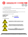
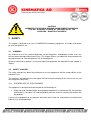
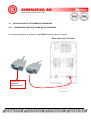
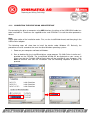
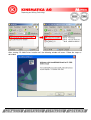
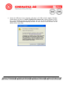
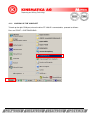
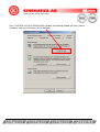
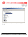
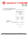
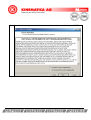
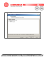
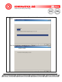
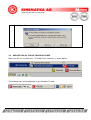
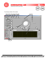
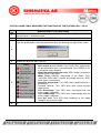
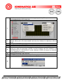
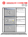
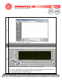
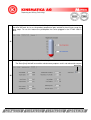
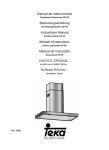
1
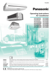
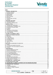
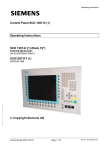
Operating Instructions USER INTERFACE V1.0 POLYTRON® PT 3100 D READ MANUAL BEFORE STARTING OPERATION! REMOTE OPERATION OF THE DRIVE USING THE SOFTWARE DOES NOT RELEASE THE CUSTOMER FROM HIS RESPONSIBILITY TO SUPERVISE THE UNIT DURING THE PERIOD OF OPERATION. This is a quality product of Luzernerstrasse 147a CH-6014 Luzern Switzerland Tel.: Fax: e-mail: +41-41-259 65 65 +41-41-259 65 75 [email protected] TABLE OF CONTENT: 1 INTRODUCTION..................................................................................................................... 3 1.1 1.2 1.3 2 OPERATING INSTRUCTIONS........................................................................................ 3 ORGANISATIONAL MATTERS....................................................................................... 4 WARNING NOTICES ...................................................................................................... 4 SAFETY.................................................................................................................................. 5 2.1 2.2 SUMMARY ...................................................................................................................... 5 SAFETY CONCEPT ........................................................................................................ 5 3 DESCRIPTION OF THE EQUIPMENT.................................................................................... 9 4 INSTALLATION AND OPERATION ..................................................................................... 10 4.1 4.1.1 4.1.2 4.1.3 4.1.4 4.2 4.3 4.4 4.5 4.6 4.7 INSTALLATION OF THE INTERFACE HARDWARE .................................................... 11 CONNECTING THE DRIVE USING RS-232 INTERFACE......................................... 11 CONNECTING THE DRIVE USING USB INTERFACE ............................................. 12 LOOKING UP THE COM PORT ................................................................................ 16 CONNECTING PT100-TEMPERATURE PROBE ...................................................... 20 INSTALLATION OF THE USER INTERFACE SOFTARE.............................................. 21 DESCRIPTION OF THE SOFTWARE FEATURES ....................................................... 26 MANUAL SPEED ADJUSTING ..................................................................................... 33 SPEED ADJUSTING USING TIME-SPEED-PROFILES................................................ 33 TEMPERATURE-DEPENDENT START/STOP ............................................................. 35 DATA-LOGGING TO MS-EXCEL®-TABLES.................................................................. 35 5 MAINTENANCE.................................................................................................................... 36 6 TROUBLE SHOOTING......................................................................................................... 36 7 ACCESORIES ...................................................................................................................... 37 8 DISCLAIMER OF WARRANTY ............................................................................................ 37 Operating Instructions User Interface PT 3100 D english / Release 1.0 page 2 of 37 1 INTRODUCTION This chapter gives information on the the structure of this document. It will assist you in making use of it and show how to find the required information quickly. 1.1 OPERATING INSTRUCTIONS PLEASE READ THESE OPERATING INSTRUCTIONS BEFORE SWITCHING ON OR OPERATING THE EQUIPMENT. THEY DESCRIBE THE USE OF THE USER INTERFACE, ITS INSTALLATION AND MAINTENANCE. THEY WILL HELP YOU AVOID ERRONEOUS USE AND SUBSEQUENT DAMAGE. ALTHOUGH POLYTRON UNITS ARE DESIGNED FOR EASE OF SERVICE, THIS DOES NOT RELEASE YOU FROM THE OBLIGATION TO INSPECT YOUR EQUIPMENT CAREFULLY AND TO CLEAN IT THOROUGHLY. KINEMATICA AG is a specialist manufacturer of machines and equipment for dispersion and mixing technology. An important objective of these operating instructions is to fully inform you, the user, about the correct and safe use of our equipment. In order to achieve this, it is essential that you should carefully study chapter 2, “Safety”, and follow the instructions in this book. 1.1.1 RANGE OF VALIDITY The information in these operating instructions relates to the POLYTRON® identified as follows: Manufacturer: KINEMATICA AG, CH-6014 Luzern Brand name: POLYTRON® POLYTRON® USER INTERFACE PT 3100 D Product name: 1.1.2 TARGET AUDIENCE These operating instructions are intended for all authorised users of our machines/equipment. We distinguish different user roles, taking account of the different demands placed on the user by the activity to be carried out. You will find the definitions of user roles with the demands on the user in chapter 2, “Safety”. You can fulfil one or more of these roles, provided that you meet the corresponding demands. Operating Instructions User Interface PT 3100 D english / Release 1.0 page 3 of 37 1.2 ORGANISATIONAL MATTERS If you are unable to find the answer to any question in the operating instructions, please contact the equipment manufacturer directly. 1.2.1 LOCATION OF THE OPERATING INSTRUCTIONS The operating instructions can only be of use to you if you always have them at hand. They should therefore always be kept at the place where the equipment is used. 1.2.2 MANUFACTURER CONTACT ADDRESS KINEMATICA AG Luzernerstr. 147a CH-6014 Luzern SWITZERLAND 1.3 Tel. +41-41-259 65 65 Fax +41-41-259 65 75 eMail [email protected] WARNING NOTICES THIS SOFTWARE IS JUST MEANT TO USE WITH A PT 3100 D DISPERGING UNIT. ANY OTHER USAGE IS NOT ALLOWED. REMOTE OPERATION USING THE SOFTWARE DOES NOT RELEASE THE CUSTOMER FROM HIS RESPONSIBILITY TO SUPERVISE THE UNIT DURING THE PERIOD OF OPERATION. CAUTION! WHENEVER THE DRIVE IS RUNNING USING REMOTE OPERATION AND A BRAKEDOWN OF THE CONNECTION OCCURS. THE DRIVE MUST BE STOPPED MANUALLY BY THE OPERATOR. Operating Instructions User Interface PT 3100 D english / Release 1.0 page 4 of 37 CAUTION! WHENEVER THE DRIVE IS RUNNING USING REMOTE OPERATION, IT IS NOT ALLOWED TO WORK AT THE DRIVE OR AT THE COUPLING – DANFER OF INJURIES! 2 SAFETY This chapter is directed at all users of KINEMATICA laboratory equipment. It includes information on safe and optimum use. 2.1 SUMMARY Any incorrect use of the installed equipment can be dangerous. Inadequately trained users can cause material damage and personal injury. This chapter informs you about the safety concept and the requirements for safe and optimum use of the equipment. All those authorised to operate, service and repair the equipment are required to study chapter 2, “Safety”. 2.2 SAFETY CONCEPT The safety concept sets down the entitlement to use the equipment and the responsibilities of the individual users. The machines and equipment are designed and constructed according to the state of the art and the recognised safety rules. 2.2.1 INTENDED USE OF THE EQUIPMENT The equipment is designed and constructed for the following use: Dispersion and homogenisation of pumpable fluid products in accordance with the technical specifications (see point 3.5) and compatibility with the materials coming into contact with the products. If you use the equipment for any purpose other than those listed, the manufacturer cannot be held liable for any resulting damage. Operating Instructions User Interface PT 3100 D english / Release 1.0 page 5 of 37 2.2.2 IMPROPER USE Any use other than the “intended use” without the written approval of the manufacturer or any operation outside the technical limits of use is improper use. 2.2.3 USER ROLES To guarantee safety, we place requirements on the users of the equipment that must be met without fail. Only persons meeting the requirements are authorised to work with the equipment. We describe all those who work with the equipment as users. Since the requirements of these users are very much dependent on their activity, we distinguish the following user roles. Contract partner: The manufacturer can impose legal obligations on the contract partner when the equipment is purchased. The contract partner is obliged to ensure that the equipment is properly used. Operating company: The operating company ensures that the equipment is properly used and authorises persons who are entitled to work with the equipment in any one of the defined user roles. They are under the obligation to instruct the users. Note: Contract partner and operating company can be the same person. Service technician: The service technician is an employee of the operating company and looks after the equipment in special operating mode(s). He is a specialist with mechanical, electrical and electronic professional training. The service technician undertakes commissioning, decommissioning service and repair of the equipment. He must be appropriately trained to be able to carry out the service work required. Operator: The operator turns the equipment on and off. In the event of an alarm signal he informs the service technician. 2.2.4 DANGER AREA System/equipment The system danger area includes the whole system/equipment including the connecting lead and controls. Proximity danger area This refers to all areas within a defined distance of the equipment. Operating Instructions User Interface PT 3100 D english / Release 1.0 page 6 of 37 User danger area This danger area includes all persons working with the equipment. 2.2.5 AREAS OF RESPONSIBILITY In order that the system/equipment can be used safely and without risk, the users in various roles bear the responsibility for particular danger areas. Contract partner: The contract partner bears the responsibility for the “proximity danger area”. Operating company: The operating company bears the responsibility for the “user danger area”. Only those users may be authorised to operate the system/equipment who fulfil all requirements of the user roles concerned. In doing so, attention must be paid to the following points: It is to be ensured that all users of the system/equipment have fully read and understood chapter 2, “Safety” and act accordingly in a safety-conscious manner. It is to be ensured that no unauthorised person carries out work with the system/equipment. It is to be ensured that users are informed of the possible risks and dangers connected with the system/equipment. It is to be ensured that those being trained or engaged in general training are under the permanent supervision of a trained and authorised person. Service technician: The service technician bears the responsibility for the “system/equipment danger area”. He ensures that the system/equipment is at all times free from technical faults, safe and functions correctly. Operating Instructions User Interface PT 3100 D english / Release 1.0 page 7 of 37 2.2.6 GENERAL SAFETY RULES Observe the following general safety rules: follow these operating instructions, in addition, observe the legal obligations and requirements for accident prevention and environmental protection of the country in which you operate the equipment, do not make any modifications to the equipment without the written authorisation of the manufacturer, only original replacement parts may be used for repairs, before any service work on the equipment, it must be ensured that the electrical supply is switched off, after any service, maintenance or repair work has been carried out on the system/equipment, it must be given a test run by the service technician. depending on the place at which it is installed, circumstances may require that hearing protection is worn when remaining in the vicinity of the equipment for long periods. Operating Instructions User Interface PT 3100 D english / Release 1.0 page 8 of 37 3 DESCRIPTION OF THE EQUIPMENT The user interface is designed for controlling the POLYTRON® System with RS232/Modbus Interface. The user interface software provides the following features controllable using a personal computer: o Manual Speed Adjustment o Free programmable, repeatable TIME-SPEED-profiles for automated work. o Readout of the product-temperature using a pt100-probe o Graphical real-time logging-diagrams for displaying process-parameters: o Actual Speed[rpm] Target Speed[rpm] Input Power[VA] Output Power[W] Motor Current[A] Torque@Shaft[Ncm] Temperature of product[°C] Temperature of controller[°C] Supply voltage[V] Line Frequency[Hz] Data-Logging of the process-parameters into MS-Excel®-tables Operating Instructions User Interface PT 3100 D english / Release 1.0 page 9 of 37 The following connection cables will be supplied with the drive PT 3100 D: RS-232 cable Connects the PT 3100 D unit directly with the computer using the RS232 interface with DB-9 connection (no driver required) Order-No. 9342334 Lengths approx. 1.8 m Adapter RS232-USB with USB cable Connects the PT 3100 D unit with the computer using the USB port via the RS-232 cable (driver on CDROM) Order-No. Lengths 9342216 approx. 0.9 m 4 INSTALLATION AND OPERATION Before starting the installation procedure, please assure that the following requirements are fulfilled: REQUIREMENTS Free Space on Harddisk Processor: Operating System installed Needed interfaces: Min. 200 MByte Min. PENTIUM® CPU with 200 MHz Windows® 98/ME/2000/XP (Windows® VISTA not tested) 1 x RS232-SERIAL-PORT or 1 x USB-PORT Operating Instructions User Interface PT 3100 D english / Release 1.0 page 10 of 37 4.1 4.1.1 INSTALLATION OF THE INTERFACE HARDWARE CONNECTING THE DRIVE USING RS-232 INTERFACE For connecting the drive to computer using RS-232 interface proceed as follows. Back side of drive PT 3100 D To personal computer’s RS232 interface Operating Instructions User Interface PT 3100 D english / Release 1.0 page 11 of 37 4.1.2 CONNECTING THE DRIVE USING USB INTERFACE For connecting the drive to computer using USB interface, the driver of the USB-RS232 cable has to be installed first. The drivers are supplied on the small CDROM. To install the driver proceed as follows: Note: Please take notice of the installation order. First, run the InstallShield wizard, and then plug in the USB to Serial adapter. The following steps will show how to install the device under Windows XP. Basically, the procedures are also somewhat the same for other Windows operating systems. 1. Power on your computer and boot to Windows. 2. Run or double-click the InstallShield driver setup program “PL-2303 Driver Installer.exe”, provided on the CDROM. The InstallShield Wizard will be displayed on your screen to inform you that the PL-2303 USB-to-Serial driver will be installed on your computer. Click Next to continue and start the installation. See the following sequence of pictures to proceed: Operating Instructions User Interface PT 3100 D english / Release 1.0 page 12 of 37 After starting “PL-2303 Driver Installer.exe” the following window will occur. Follow the steps as described Operating Instructions User Interface PT 3100 D english / Release 1.0 page 13 of 37 3. Wait until the InstallShield Wizard informs you that driver installation is successfully installed. Click the Finish button to close the InstallShield program. If you have plugged the cable into the PC while running the setup installation, please unplug and replug the cable for the system to detect the device. Operating Instructions User Interface PT 3100 D english / Release 1.0 page 14 of 37 4. Locate the USB port of your computer and plug in the USB to Serial adapter. Windows should detect the driver as Prolific USB-to-Serial Comm Port. Before Windows installs this, it may prompt you that this device driver has not yet passed Windows XP Logo compatibility. Click Continue Anyway. Windows will then start to install the driver for the USB-to-Serial Comm Port. Operating Instructions User Interface PT 3100 D english / Release 1.0 page 15 of 37 4.1.3 LOOKING UP THE COM PORT To look up the right COM port, where the drive PT 3100 D is connected to, proceed as follows: Press on START > SYSTEMCONROL. Operating Instructions User Interface PT 3100 D english / Release 1.0 page 16 of 37 Press “SYSTEM” in the SYSTEMCONTROL window, the following window will occur, choose “Hardware” and press the button “Device Manager” Operating Instructions User Interface PT 3100 D english / Release 1.0 page 17 of 37 Click on “connections” to look up the right COM port where the PT 3100 D is connected. This port number has to be choosen in the settings menu of “User Interface PT 3100 D”. See page 28 / 16.1 Operating Instructions User Interface PT 3100 D english / Release 1.0 page 18 of 37 After having installed the driver for the USB-RS232 cable, proceed as follows for connecting the required cables Back side of drive PT 3100 D RS232 cable To personal computer’s USB interface RS232-to-USB cable Operating Instructions User Interface PT 3100 D english / Release 1.0 page 19 of 37 4.1.4 CONNECTING PT100-TEMPERATURE PROBE For connecting the pt100-temperature probe (optional, order-no. 9115019) to the drive, plug in the probe into the indicated plug socket. Back side of drive PT 3100 D Plug socket pt100 probe for Operating Instructions User Interface PT 3100 D english / Release 1.0 page 20 of 37 4.2 INSTALLATION OF THE USER INTERFACE SOFTARE 1. Put the CD-ROM into a CD-ROM-DRIVE 2. Open the CD-ROM directory or wait for Autoload 3. The following window opens. Click INSTALLATION to install the user interface PT 3100 D. Click USER MANUAL to open the manual. (Acrobat Reader required) If needed, click “Acrobat Reader” to install Operating Instructions User Interface PT 3100 D english / Release 1.0 page 21 of 37 4. Follow the steps in the picture, press “NEXT” Operating Instructions User Interface PT 3100 D english / Release 1.0 page 22 of 37 5. Read the Licence Agreement, indicate “I accept Licence Agreement” and press “NEXT” Operating Instructions User Interface PT 3100 D english / Release 1.0 page 23 of 37 6. Press “NEXT” and the installation of the software will start. Operating Instructions User Interface PT 3100 D english / Release 1.0 page 24 of 37 7. Wait while Installation procedure will be performed. Do not turn off the computer during install. When the installation is completed, press “FINISH” Operating Instructions User Interface PT 3100 D english / Release 1.0 page 25 of 37 8. 4.3 Restart your System that the User Interface will be activated. DESCRIPTION OF THE SOFTWARE FEATURES When your PC has restarted start “PT 3100 D User Interface” as shown bellow: The following icons will be displayed in your Windows Taskbar: Operating Instructions User Interface PT 3100 D english / Release 1.0 page 26 of 37 The following window will be loaded: 15 16 17 18 19 20 21 22 8 9 1 2 3 4 5 7 10 6 11 12 7 14 13 Operating Instructions User Interface PT 3100 D english / Release 1.0 page 27 of 37 THE FOLLOWING TABLE DESCRIBES THE FUNCTIONS OF THE FEATURES NO. 1 TO 23: Feat. No. 1 2 DESCRIPTION OF THE FUNCTIONS Clicking this button starts communication with the device. Green light indicates that communication is activated and ok. Clicking this button starts a defined TIME-SPEED-profile (see 20) Clicking this button makes the software looking for an installed pt100-temperature probe. When the pt100-probe is not connected to the drive the following message will be shown: 3 4 5 6 Clicking this button activates the temperature dependent START/STOP-function in between the drive will work. (see 21) The state field indicates any conditions of the drive: Drive health general indicator: Turns RED if any malfunctions will be detected or drive is not connected. Turns GREEN if unit a connection works properly. Motor Blocked Speedsensor fault: RED if motor is blocked or speed sensor is damaged. Motor Temp: Indicates overheating of the motor: Turns “YELLOW” when motor is heaten up strongly and turns “RED” when motor is overheated Controller Overheated: Turns RED when speed controller is overheated Overload indicator: Turns RED when drive cannot achieve target speed. Line Overvoltage: Turns RED when overvoltage from the mains supply is detected Line Undervoltage: Turns RED when undervoltage form the mains supply is detected Line Syc. fault: Turns RED when frequency of the supply voltage is out of normal range Clicking this button will erase the graphical data-logging to restart at the beginning (see 12) Operating Instructions User Interface PT 3100 D english / Release 1.0 page 28 of 37 Checkboxes for choosing parameters to be logged graphically. Two parameters can be visualized graphically at the same time. 7 8 9 10 11 12 13 14 With this controller the speed can be adjusted. Move the mouse-indicator over the speedindicator (blue), press the mouse button and move the indicator for adjusting a desired speed. Clicking the UPDATE-button will send the adjusted speed to drive. Speed scale from 0 to 30’000 RPM In this textbox the a desired speed can be entered manually This is area used for the visual data logging consisting of a horizontal TIME-axis and 2 vertical axis where the parameters SPEED, OUTPUT-POWER, MOTOR-CURRENT and TEMPERATURE OF THE PRODUCT will be indicated. SPEED will always be indicated, others are optional to choose. The RESET-button will be used for resetting the drive after critical stops and errors such as blocking, overheating & spin start fault The STOP-button will stop the drive and the data logging at run-time. For quitting the User Interface click as follows: 15 Operating Instructions User Interface PT 3100 D english / Release 1.0 page 29 of 37 By clicking on SETTING the following window will 16.1: In this field your serial port number for the drive can be set. be opened: (see chapter 4.1.3 to learn how to detect you serial port number) 16.2: In this field the baud rate is indicated. 16.1 Click OK when SETTINGS are done. 16.2 16.3: In this field you can choose your directory for saving logged ExcelTables 16.4: In this field you can adjust the logging frequency. As default the parameters will be logged to the Exceltable every second. 16 16.4 16.3 Click OK when SETTINGS are done. 16.5: Choose your preferred unit for the TIME-axis (see 12): “seconds” or “minutes” 16.5 Operating Instructions User Interface PT 3100 D english / Release 1.0 Click OK when SETTINGS are done. page 30 of 37 Save and load TIME-SPEED-profiles (see 20) 17 Profiles will be saved using the “.txt”-format. 18 Clicking this button provides information about the version & the manufacturer. 19 The STATIC-page is visible at first after having started the User Interface. On this page you can define TIME-SPEED-profiles and save them to your harddisk (see 17): 20 20.1 20.2 20.3 The time-speed steps can be entered as shown in the example above. 20.1: Line for entering point of time when the drive shall accelerate to another speed value 20.2: Line for entering the speed which the drive will accelerate for 20.3: To erased a profile, click RESET-button. Operating Instructions User Interface PT 3100 D english / Release 1.0 page 31 of 37 In this page you can enter 2 values for defining a temperature-range for the product wherein the drive will work. As far as the product temperature gets outside of the min/max range the drive stops. To use this feature the pt100-probe has to be plugged in the PT-MR 3100 D drive. 21 On this page every parameter can be viewed as plain text. The State [Hex] field will be used for maintenance purposes and is not relevant for normal operation. 22 Operating Instructions User Interface PT 3100 D english / Release 1.0 page 32 of 37 4.4 MANUAL SPEED ADJUSTING Assure that your drive system is turned on and the installation & cabling is done according to the scheme in chapter 4.1: 1. If the drive is not yet connected, please press button (1) to connect to the drive system. 2. Use the reference-speed knob (8) to set your desired speed or type your desired speed in the box below (11). 3. Press UPDATE to (9) execute. The drive should now change the speed to the set value. 4. For altering the speed again proceed with step 2. 5. To stop the drive instantly, press the STOP-button (14). 4.5 SPEED ADJUSTING USING TIME-SPEED-PROFILES Assure that your drive System is turned on and the installation & cabling is done according to the scheme in chapter 4.1. The time-speed profile consists of a sequence from TIME/SPEED records. Every TIME/SPEED points means a change to this “SPEED” at this “POINT OF TIME”. So the entered values are POINTS OF TIME when the speed will be changed to the desired value. The speed will remain at a constant value until the next POINT OF TIME and so on. The TIME-POINTS are absolute time-values not delta-values. The desired unit (min or sec) can be adjusted in the menu SETTINGS (16) To define a time-speed-profile proceed as follows: 1. 2. 3. 4. 5. Press Button (1) to connect to the drive system. Enter the time-points in the box (20.1) o Click into the desired box using the mouse pointer. o Enter the value using your keyboard. o Press ENTER on your keyboard to confirm value Enter the speed in the associated box (20.2) below. o Click into the desired box using the mouse pointer. o Enter the value using your keyboard. o Press ENTER on your keyboard to confirm value Repeat steps 2. & 3. to generate any specific speed profile. The profile will be visualized in the window. Press (2) to execute the profile. REMOTE OPERATION THE DRIVE USING TIME-SPEED PROFILES DOES NOT RELEASE THE CUSTOMER FROM HIS RESPONSIBILITY TO SUPERVISE THE UNIT DURING THE PERIOD OF OPERATION. Operating Instructions User Interface PT 3100 D english / Release 1.0 page 33 of 37 To receive a valid profile there must always be entered a time and a speed-value as a pair. A speed value without corresponding time value lead to invalid profile – and vice versa. See example as follows: ok ok wrong! Speed value is missing. The following error message will occur when the above profile will be executed. See example for a correct speed profile: Operating Instructions User Interface PT 3100 D english / Release 1.0 page 34 of 37 4.6 TEMPERATURE-DEPENDENT START/STOP Click the Temperature Limits Register (21). You can define your temperature limits. Press the Temperature Limits Button (4) to activate this feature. The drive stops whenever the temperature of your product is out of the defined range. DATA-LOGGING TO MS-EXCEL®-TABLES 4.7 Every time a job according to chapter 4.4 or 4.5 will be started, the data-logging into a Excel®-table will be activated in the background. The following data will be logged: Actual Speed[rpm] Target Speed[rpm] Input Power[VA] Output Power[W] Motor Current[A] Torque@Shaft[Ncm] Temperature of product[°C] Temperature of controller[°C] Supply voltage[V] Line Frequency[Hz] Operating hours[h] State Button-Log Before starting, a directory for saving the logged-data should be defined using feature (16.3) The data-file has always the name “LOGDATA.CSV” and must be opened using MSEXCEL®. When a job is done or STOP will be pressed, logging will be stopped too. For every new start of a job according to chapter 4.4 or 4.5 the logging-function will write data into the next row after the last STOP in the table. The automatically generated logfile “Logdata.csv” has to be closed . If not the values will not be written into the logfile. To save a table and avoid overwritting, the table can just to be renamed. The “Logdata.csv” can be deleted at any time when no job is in progress. Whenever a job will be started and no “Logdata.csv”-file exists it will be generated automatically. Operating Instructions User Interface PT 3100 D english / Release 1.0 page 35 of 37 5 MAINTENANCE Make sure that the provided hardware will not be subjected to high temperatures or humidity. 6 TROUBLE SHOOTING PROBLEM The following message opens when trying to connect to the drive. The following message opens when trying to connect to ext. temperature probe. The following message opens when trying to connect to the drive. Data will not be logged to the Excel table REASON CORRECTIVE MEASURES Drive not turned on Wrong COM/USB port adjusted. Check that the drive is turned on. Check and correct the serial port number for the drive. Defective cable/adapter connection cable Replace the defective cable/adapter. Pt100 probe not connected Assure that the hardware is connected exactly. Pt100 probe defective Check pt100 probe, if necessary replace defective probe. Wrong COM/USB port adjusted Check and correct the serial port number COM/USB port does not exist Check and correct the serial port number for the drive. COM/USB port is occupied and should be reset Check the ports for occupation. If this does not helped, shut down & restart the computer Table “Logdata.csv” Close “Logdata.csv” and restart your is opened in Excel. job. For problems related to the drive, see corresponding manual. Operating Instructions User Interface PT 3100 D english / Release 1.0 page 36 of 37 7 ACCESORIES pt100 probe For measuring the product temperature. The probe can be plugged into connection on the back side of the drive Order-No. 9115019 Lengths Approx. 2 m 8 DISCLAIMER OF WARRANTY In case of any accident caused by misapplication of the software and/or hardware by the user, KINEMATICA AG or its representations will not assume any liability for possible remote damages. The owner/operator has assure that the system will be operated according to the guidelines in the stated in the operating instructions. REMOTE OPERATION OF THE DRIVE USING THE SOFTWARE DOES NOT RELEASE THE CUSTOMER FROM HIS RESPONSIBILITY TO SUPERVISE THE UNIT DURING THE PERIOD OF OPERATION. KINEMATICA AG Luzernerstr. 147a CH-6014 Luzern SWITZERLAND Tel. +41-41-259 65 65 Fax +41-41-259 65 75 eMail [email protected] Windows® 98, Windows® ME, Windows® 2000, Windows® XP, Windows® VISTA, Excel® are registered Trademarks of the Microsoft Corporation Operating Instructions User Interface PT 3100 D english / Release 1.0 page 37 of 37