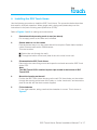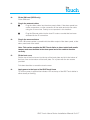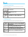
1
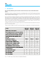
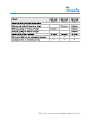
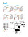
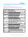
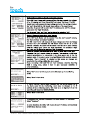
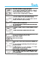
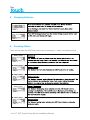
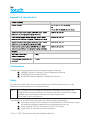
AW IRIS Touch Home Series Manual FRONT COVER ONLY AW MAY2013 v1_Layout 1 29/05/2013 19:04 Page 1
Alarm over IP
IRIS Touch Home
Installation Manual
Version 1.0 ENGLISH
Now certified
and compliant with
EN50131, EN50136
Security Grade 4
ATS6
1. Introduction
No more bulky batteries, just one sleek unit with 24 hours or more runtime after mains
failure
To meet the rapidly increasing demand for cost effective Alarm over IP (AoIP) equipment for the
SME and home markets, Chiron has developed the IRIS Home unit based on its successful IRIS
Touch 100 and Touch 200 ranges.
By using advanced software intelligence and power management the IRIS Touch units can offer
24 hours or more for Grade 2/3 alarm systems, without the need for bulky batteries. The unit can
be powered from a mains supply, or the battery of an alarm panel. In the case of external mains
power failure, the alarm battery backup will not be used and internal IRIS Touch Home batteries
take over. The sleek unit offers all the benefits and features of other diallers in the IRIS Touch
range, including remote access for Upload/Download.
The IRIS Touch Home can be supplied in three forms: Home 00, Home 20 and Home 40. All come
with a fit and forget solution.
There are three models in the IRIS Touch Home family for single path or dual path transmission.
2 of 17 IRIS Touch Home Series Installation Manual
IRIS Touch Home Series Installation Manual 3 of 17
Figure 1
Figure 2
Figure 3
Figure 4
Figure 5
Figure 6
4 of 17 IRIS Touch Home Series Installation Manual
2. Configuration options
The IRIS range of alarm dialers allows alarm systems to move into fixed line (Ethernet) and/or
wireless networks (GPRS) without the need to upgrade or replace the alarm system.
In some smaller alarm panels however the battery backup within the panel is not sufficient to
power both the panel and an IRIS Touch dialler for a continued period of operation once mains
power is lost. The IRIS Touch Home enhances the IRIS Touch range by providing both the
power and battery backup supply in a single unit.
The IRIS Touch Home offers various power supply and battery charging options:
2.1.
Powering from an independent mains adapter
Power is provided from a separate DC mains power adapter provided for use with the IRIS
Touch Home. This mode can be used where a mains power socket is available. The mains
adapter should be specified to deliver up to 1A at 9-28V DC or 7V-20V AC.
Please refer to Figure 1
2.2.
Intelligent powering from an alarm panel AUX output
This uses an auxiliary power output from the panel (such as that used to power a siren). This is
intelligently controlled by the IRIS Home with power only being taken when mains power to the
alarm panel is available. This avoids the alarm panel battery life being shortened during mains
power failure. This mode can be used where the alarm panel has an auxiliary DC power output
of 9V to 35V DC that can deliver at least 500mA above the requirements of any other attached
device.
Please refer to Figure 2
2.3.
Intelligent powering from the panel mains adapter
Power is provided via the low voltage AC or DC adapter used by the alarm panel. Because the
IRIS Touch Home senses the output voltage level of the alarm panel mains adapter, it draws no
current while the panel power supply is fully loaded. In this mode the power input to the alarm
panel must be accessible and has a connector for an additional cable. This mode can be used
where 500mA more than that required by the panel itself can be delivered by the adapter.
Please refer to Figure 3
2.4.
Intelligent powering from the alarm panel battery charger
Power will only be taken when mains power to the alarm panel is available, preventing alarm
panel battery life being shortened during mains power failure. This mode can be used where
the alarm panel uses a 12V battery, the charger can deliver more than 500mA, leaves its
battery on charge at all times and does not have its own intelligent battery charging mode.
Please consult the alarm panel supplier if in doubt. This method will affect the recharge time of
the alarm panel battery.
Please refer to Figure 4
IRIS Touch Home Series Installation Manual 5 of 17
3. Before you start…
3.1.
Monitoring Centre
Make sure that the monitoring centre to which the IRIS Touch Home will send alarm signals is
equipped with the appropriate IRIS receiving system. The following information should be
obtained from the monitoring centre.
•
•
3.2.
Dialler account number
Monitoring centre IP address
GPRS SIM Card and Access Point Name
If the installation uses GPRS then a SIM card will be required. The IRIS Touch Home will also
need to be given a GPRS ‘Access Point Name’ (APN). This can be obtained from the SIM card
provider.
3.3.
Batteries
The IRIS Touch Home requires 8 x 1.5V NiMh AA size rechargeable batteries (not included).
The required battery capacity is 2050mAH minimum and ideally they should feature low selfdischarge. Batteries must be approved to IEC61951-2 (EN61951-2).
Recommended manufacturers/types are:
•
•
GP ReCyko 210AAHCB
Annsman maxE 2100
Other battery types - including non-rechargeable batteries - must not be used.
3.4.
Package contents
•
•
•
•
•
•
•
IRIS Touch Home plastic housing fitted with the dialler PCB, PSU PCB, power and
interconnect cables.
3 x screws and plugs for fixing the housing to a flat surface.
Antenna
Ethernet cable
Stylist
RJ11 cable (Dial Port)
18k ohms sense resistor
3.5.
Ferrites
If the installation is in a residential environment you will need to fit ferrite chokes to the Ethernet
cable if used. This is required to ensure compliance with EMC Class B emissions. Suitable
ferrites can be obtained from Chiron.
6 of 17 IRIS Touch Home Series Installation Manual
4. Installing the IRIS Touch Home
Use the following procedure to install the IRIS Touch Home. The procedure below describes
that used for dual path operation. Where single path is being used please step over the
instructions for the path not being used (Ethernet or GPRS).
Refer to Figures 5 and 6 for cabling and connections.
1.
Determine which powering mode to use (see above).
Do not apply power to the dialler until indicated.
2.
Decide where to run the cables
Decide the best way to run the cables that will be required. Panel dialler interface
cable, Ethernet cable and/or GSM Antenna.
This can be either:
g Behind the unit (through the wall).
g Through the bottom of the back plate of the unit via the ‘knock outs’.
3.
Disassemble the IRIS Touch Home
Remove the two case fixing screws and open the unit and remove the IRIS Touch
dialler PCB.
Note:
The IRIS Touch PCB is retained by two clips located at the bottom of IRIS
Touch PCB.
4.
Mount the housing on the wall
Position the IRIS Touch Home housing on the wall. Drill three holes, put the cables
through the opening at the base of the plate, or via the ‘knockouts’, and secure the
plate to the wall with the three screws supplied.
5.
Fit the batteries
Fit the eight batteries, taking care that the orientation is correct. This is shown in
Figure 5.
IRIS Touch Home Series Installation Manual 7 of 17
6.
Plug in the connectors
Please refer to Figure 6
Do not connect the power source or apply power until later.
•
Mode 1) Use a DC mains power adapter and wire to the DC input of the
IRIS Touch Power Home PSU PCB board.
•
Mode 2) Wire the panel auxiliary output to the DC input of the IRIS Touch
Home charger board.
Fit a separate cable from the Sense input of the charger board, to either
the alarm panel input from its own mains adapter or from a configurable
output from the alarm panel that will signal AC fail. Please observe that the
Sense input is only suitable for low voltage DC (max 28V) or AC (max 20V).
•
Mode 3) (DC or AC) Wire the output of the panel mains adapter (500mA
at 9-28V DC or 7V-20V AC) to the DC or AC (as appropriate) input of the
IRIS Touch Home PSU PCB board.
•
Mode 4) Wire the output of the panel battery charger to the DC input of
the IRIS Touch Home charger board.
7.
Fit the tamper switch springs
The IRIS Touch Home is protected against tampering (e.g. removal from the wall or
opening of the case) by two tamper switches on either side of the dialler PCB. These
switches are held by springs that press against the wall and the top cover. Before
fitting the unit, make sure the springs are fitted correctly to the tamper switches.
8.
Fit the PCB to the back plate
Fit the PCB to the back plate, by sliding under the hooks at the top and pushing into
the catches at the bottom. Unlike the standard IRIS Touch dialler, screws are not
required.
Ensure that the rear tamper spring is located within the tamper tube.
9.
Connect relevant cables to the IRIS Touch PCB
g Ribbon cable from PSU PCB to IRIS Touch PCB
g Power connection from PSU PCB to IRIS Touch PCB
g Ethernet cable (cream) (Ethernet only).
g Dialler cable (grey).
g GSM antenna (GPRS only).
Note the final positioning of the antenna is determined by a successful network
scan to be performed as part of the configuration of the IRIS Touch dialer.
10.
Fit the SIM card (GPRS only)
8 of 17 IRIS Touch Home Series Installation Manual
10.
11.
Fit the SIM card (GPRS only)
Fit the SIM card.
Plug in the external cables
Plug the dialler cable into the alarm panel dialler. If the alarm panel has
screw connections, cut the connector off the cable and strip the cable
using the 2 inner wires. Polarity is not important in this instance.
g
g
12.
Plug the Ethernet cable into the local IP router or socket that has been
allocated for the IP connection.
Plug in the sense resistors
Fit the 18K sense resistor in parallel with the dialler output of the alarm panel, at the
alarm panel end of the cable.
Note: This resistor enables the IRIS Touch dialler to detect cable faults and/or
tampers and must be fitted at the alarm panel end of the cable to function
correctly.
13.
Fit the front cover
Slot the top of the front cover into the top of the back plate and click the bottom of
the front cover to the bottom of the back plate. Fix in place with the two screws
provided.
Pull down the slider to reveal the touch screen.
14.
Apply power to the input of the IRIS Touch Home
To confirm power is applied the indicator LED at the top of the IRIS Touch dialler is
either steady or flashing.
IRIS Touch Home Series Installation Manual 9 of 17
5. Entering the Installers Menus
On first power up the installer is prompted to select the language required. From there the
installer menus can be accessed:
6. GPRS Network Scan
It is strongly recommended that this scan is carried out to ensure there is sufficient network
coverage from at least two wireless base stations to warrant a reliable connection.
10 of 17 IRIS Touch Home Series Installation Manual
7. Installation Wizard
The Installation wizard guides you through the set up process.
The wizard informs you of successful progress as you go along and in general select
“Continue” to carry on. If there is a problem you will be told what it is and not allowed to
continue until it is solved.
IRIS Touch Home Series Installation Manual 11 of 17
12 of 17 IRIS Touch Home Series Installation Manual
IRIS Touch Home Series Installation Manual 13 of 17
8. Changing Batteries
9. Checking Status
There are five states the IRIS Power Home can be operating in – these are explained below:
14 of 17 IRIS Touch Home Series Installation Manual
10. Maintenance Recommendations
The batteries should be routinely replaced every two years.
When the batteries are replaced, the installer must tick the ‘New Battery’ tick box found in the
Battery Status section within the Power Interface settings
IRIS Touch Home Series Installation Manual 15 of 17
Appendix A. Specification
Conformance
The IRIS Touch Home complies with the following European Directives:
g 1999/5/EC (Radio & Telecoms Terminal Equipment Directive)
g 2006/95/EC (Low Voltage Directive)
g 2004/108/EC (Electromagnetic Compatibility Directive)
Safety
Care should be taken when interconnecting telecommunications equipment that only like
interfaces are interconnected to avoid safety hazards.
SELV:
SELV (Safety Extra-Low Voltage) is defined as a secondary circuit which is so
designed and protected that under normal and single fault conditions the voltage
between any two accessible parts does not exceed a safe value
(42.4V peak or 60V dc maximum)
The interfaces on the IRIS Touch Home have the following safety classifications:
g Dial capture interface: SELV suitable for connection to the TNV interface of single
line telecommunications equipment such as telephones faxes, etc.
g Power Interface: SELV for connection to a DC or AC supply
g Inputs: SELV for connection to alarm output pin
16 of 17 IRIS Touch Home Series Installation Manual
AW IRIS Touch Home Series Manual FRONT COVER ONLY AW MAY2013 v1_Layout 1 29/05/2013 19:04 Page 10
CHIRON
SE
SECURITY
CURIT Y C
COMMUNICATIONS
OMMUNICATIONS
TION
Telephone: +41 43 508 08 66
Fax: +41 43 508 08 75
[email protected]
www.chironsc.com
CHIRON SECURITY COMMUNICATIONS AG
WORLD TRADE CENTER, OFFICE 70
LEUTSCHENBACHSTRASSE 95
8050 ZURICH, SWITZERLAND
The information contained is supplied without liability for any errors or omissions. No part may be reproduced or
used except as authorised by contract or other written permission. The copyright and foregoing restriction on
reproduction and use extend to all media in which the information may be embedded.
© 2013 Chiron Security Communications AG