1
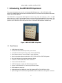
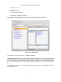
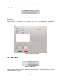
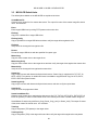
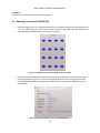
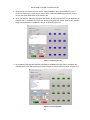
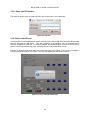
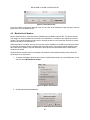
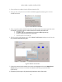
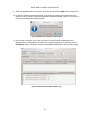
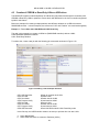
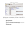
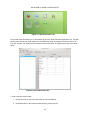
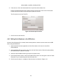
M5100-PR & M5208 USB 3.0 Duplicator International Microsystems Incorporated M5100-PR & M5208 USB 3.0 Duplicator User Manual Version 1.3 M5100 USB 3.0 & USB 2.0 DUPLICATOR Copyright 2012 International Microsystems, Inc. All rights reserved. International Microsystems, Inc. 556 Gibraltar Drive Milpitas, CA 95035 U.S.A. Telephone: FAX: Email: Website: Manual Version: 408-942-1001 408-942-1051 [email protected] www.imi-test.com 1.3 on Aug 29, 2013 This manual is intended to be used for the following IMI USB duplicators – M5116-PR, M5132-PR & M5208. Although the manual references M5116-PR, all functions and operations described apply to M5132-PR & M5208 also. Information in this manual is subject to change without notice and does not represent a commitment on the part of vendor. IMI reserves the right to change the hardware and software configurations on all its products without prior notice when deemed necessary for product improvement. 1 M5100 USB 3.0 & USB 2.0 DUPLICATOR 2 M5100 USB 3.0 & USB 2.0 DUPLICATOR Table of Contents 1 2 Introducing the M5100-PR Duplicator .................................................................. 5 1.1 Key Features ....................................................................................................................... 5 1.2 Technical Specifications ..................................................................................................... 6 1.3 Package Contents ............................................................................................................... 6 1.4 Things to remember ............................................................................................................ 6 Using the M5100-PR Duplicator (Stand Alone) .................................................... 8 2.1 M5100-PR Power up ........................................................................................................... 8 2.2 M5100-PR Power Down ..................................................................................................... 8 2.3 Quick Summary of M5100-PR Keys and Functions ........................................................... 9 2.4 COPY using the M5116-PR .............................................................................................. 10 2.5 COPY-VERIFY using the M5116-PR ................................................................................ 11 2.6 VERIFY using the M5116-PR ........................................................................................... 12 2.7 FORMAT & ERASE using the M5116-PR ........................................................................ 13 2.8 Menu Functions on the M5116-PR ................................................................................... 14 2.8.1 2.8.2 2.8.3 2.8.4 2.8.5 2.8.6 2.8.7 3 Run Job ................................................................................................................ 14 Result ................................................................................................................... 15 Save Log .............................................................................................................. 16 Information............................................................................................................ 18 Software Update ................................................................................................... 18 Restart Server ...................................................................................................... 19 Shut Down ............................................................................................................ 20 Using M5100-PR with M51W GUI ........................................................................ 21 3.1 Starting the M51W Graphical User Interface (GUI) .......................................................... 21 3.2 M51W Menu ...................................................................................................................... 23 3.2.1 3.2.2 3.2.3 3.2.4 3.2.5 File Menu .............................................................................................................. 23 Connection Menu ................................................................................................. 24 Admin Menu ......................................................................................................... 24 Tools Menu ........................................................................................................... 25 Help Menu ............................................................................................................ 25 3.3 M5100-PR Default Jobs .................................................................................................... 26 3.4 Running a job using the M51W GUI ................................................................................. 27 3.5 Log Viewer ........................................................................................................................ 29 3.6 Creating and Editing a Job using M51W GUI ................................................................... 31 3.7 Available Operations for a New job in M5100-PR ............................................................ 31 3.7.1 3.7.2 3.7.3 3.7.4 3.7.5 Set Values ............................................................................................................ 31 Check Parameters ................................................................................................ 33 Program ................................................................................................................ 34 Verify .................................................................................................................... 34 Program-Verify ..................................................................................................... 34 3 M5100 USB 3.0 & USB 2.0 DUPLICATOR 3.7.6 3.7.7 3.7.8 3.7.9 3.7.10 3.7.11 3.7.12 3.7.13 3.7.14 3.7.15 3.7.16 3.7.17 3.7.18 3.7.19 3.7.20 3.7.21 3.7.22 Create Master File ................................................................................................ 35 Erase .................................................................................................................... 35 Smart Program ..................................................................................................... 35 Smart Verify .......................................................................................................... 35 Smart Program-Verify........................................................................................... 35 Smart Create Master File ..................................................................................... 35 Smart Erase.......................................................................................................... 35 File Copy .............................................................................................................. 36 File Verify.............................................................................................................. 36 File Copy-Verify .................................................................................................... 36 Create Master File Pattern ................................................................................... 36 USB Controller ..................................................................................................... 36 Set LUN (Logical Unit) .......................................................................................... 36 Kiosk Mode ........................................................................................................... 37 TCL Command ..................................................................................................... 37 Format Device ...................................................................................................... 37 Check Device Config ............................................................................................ 38 3.8 Operation Modes and Password Editing .......................................................................... 39 3.9 M5100-PR Tools Menu ..................................................................................................... 40 3.9.1 3.9.2 3.9.3 3.9.4 3.9.5 3.9.6 Update .................................................................................................................. 40 Create Master File ................................................................................................ 40 Checksum Master Device .................................................................................... 41 Set Operator ......................................................................................................... 42 Barcode ................................................................................................................ 42 Enter Job PO Number .......................................................................................... 43 3.10 Fully Loaded Check .......................................................................................................... 43 4 M5100-PR Special Features ................................................................................ 44 4.1 Barcode Launch of Jobs ................................................................................................... 44 4.2 Module Serial Number ...................................................................................................... 45 4.3 Creation of CDROM or Read-Only LUNs on USB drives ................................................. 48 4.4 USB Serial Number Generation ........................................................................................ 53 4.4.1 4.4.2 Serial Number Generation .................................................................................... 53 Writing Serial Numbers to the USB drives ........................................................... 56 5 M5100-PR Calibration .......................................................................................... 58 6 Customer Support................................................................................................ 58 Appendix I : M5100-PR Software Release History ................................................... 59 4 M5100 USB 3.0 & USB 2.0 DUPLICATOR 1 Introducing the M5100-PR Duplicator This manual is intended to be used for the following IMI USB duplicators – M5100-PR (M5116-PR, M5132-PR) & M5208. Although the manual references M5116-PR, all functions and operations described apply to M5132-PR & M5208. The M5100-PR is a high speed USB duplicator that can copy, verify and erase up to 15 or 31 USB devices at a time. It can be operated stand alone as well as using professional M51W GUI software. The M5100-PR supports super speed USB 3.0 devices as well as high speed USB 2.0 devices. It has copy speeds of up to 3 GB/min for USB 3.0 devices and is one of the fastest USB duplicators available today. Figure 1-1 M5116-PR USB 3.0 Duplicator 1.1 Key Features USB 3.0 and 2.0 Support Professional GUI for enhanced job set up and control Front panel function keys for Copy, Verify, Format (with Erase) Binary image sector by sector copying for exact duplication Smart copy which copies only the data for FAT, FAT32, NTFS, exFAT File Systems Bit by bit verification and automatic checksum display Checksum, CRC32, MD5 Hash, SHA1 Verification Clean and Format USB drives USB Test Function to check the USB device parameters Support for SD, MicroSD, CF cards using USB card readers SQL database to store logs Optional Smart Copy Support for Linux File Systems (EXT2, EXT3, EXT4 ) & HFS+ Optional Support to Create Read-Only/CDROM LUNs for USB devices with specific controllers 5 M5100 USB 3.0 & USB 2.0 DUPLICATOR 1.2 1.3 1.4 Technical Specifications Model M5100-PR Display 2X 24 LCD Input 9 Front panel push buttons Supported Media USB 3.0, USB 2.0 Dimensions M5116-PR: 9.5” X 11” X 15.5” M5132-PR: 9.5” X 15” 18.5” M5208: 9.5” X 11” X 15.5” Weight M5116-PR: 12lbs M5132: 28 lbs M5208: 12 lbs Power Supply 100-250 VAC, 300W Operating Temperature 40F – 120F ROHS Compliant Yes Package Contents M5100-PR USB Duplicator AC Power Cord M5100-PR User Manual Things to remember MASTER SLOT: The master slot is the very first slot, also marked as “MASTER”. DEVICE LED DETECTION: The Green LEDs above each USB port will flash as soon as a USB device is inserted and recognized by the M5100-PR. BUSY SIGNAL: The Green LEDs above each USB port will flash when the duplicator is in use and will stay solid Green after a successful duplication. RED LED MEANS FAIL: If the duplication is not successful, it is indicated by a solid Red LED above the failed USB device. 6 M5100 USB 3.0 & USB 2.0 DUPLICATOR SAME DEVICES EQUALS SUCCESSFUL DUPLICATION: Although many USB devices from different manufacturers may be branded with the same size (say 512 MB), in reality they may have a slightly different number of sectors or total number of bytes. IMI highly recommends that the user only duplicate from master devices that are the exact same type and manufacturer as the copy devices. CLEAN THE MASTER DEVICE BEFORE COPY: When creating a device to be used as a master for duplication, IMI recommends that the device designated to be the master should be reformatted and/or erased before copying files over to it to make the master. CARD READER SUPPORT: USB card readers can be used to read/write flash memory media such as SD cards, MicroSD cards, CF cards on the M5100-PR. Most USB adapters can be used with the M5100-PR. However, IMI cannot guarantee that all readers will work with all types of inserted flash media. For successful duplication, all USB adapters should be the same manufacturer and model and all flash memory devices (Master and Copy drives) should be from the same manufacturer and be of the same type and size (if possible, purchased in trays). 7 M5100 USB 3.0 & USB 2.0 DUPLICATOR 2 Using the M5100-PR Duplicator (Stand Alone) 2.1 M5100-PR Power up 1. Attach the provided AC power cord on the side/rear of the unit and connect it to an electrical outlet. 2. Press the “Green” power button located above the AC input on the side/rear panel of the M5100-PR. 3. After the power is turned on, the M5100-PR takes about a minute to configure the machine, place its power up screen on the LCD screen and sound a short sequence of five notes. Once the unit is booted, the top line of the LCD screen displays the current software version of the M5100-PR and the second line of the LCD shows the current menu function that can be selected using the START key. **M51xxP: ->Run Job SW Ver 1.xx ** 4. The M5100-PR is now ready to use for duplication. 2.2 M5100-PR Power Down There are three methods for shutting down the M5100-PR. Shut Down Method 1: The M5100-PR can be powered down from the menu function on the LCD screen. Press the DOWN key until the LCD screen displays “Shut Down” function. Press the Green START button twice, first to select and then to confirm the shut down operation. Please refer to section 2.8.6 for a detailed description of the Shut Down operation. Shut Down Method 2: This is the preferred method using the LCD Monitor. Exit the M51W GUI. Then Click on the Linux “Start” menu, which is located at the lower left corner. Then select “Shutdown Computer” in the “Leave” tab. This will shut down the M5100-PR properly. Please refer to Chapter 3 on how to use the M51W GUI. Shut Down Method 3: Do not use this method unless method 1 & 2 cannot be used. Shutting down the M5100-PR using the Power Key may damage the M5100-PR file system and cause operational problems. Press the Green Power button on the side/rear panel of the M5100-PR and hold it until the M5100-PR shuts down. Release the Power button as soon as the M5100-PR LCD turns off. If you continue to hold the key down, you will inadvertently power up the system. 8 M5100 USB 3.0 & USB 2.0 DUPLICATOR 2.3 Quick Summary of M5100-PR Keys and Functions The M5100-PR can be completely operated from its front panel keypad and LCD screen. The front panel has 9 keys and a LCD screen which is a 2 line, 24 character display. Figure 2-1 shows the close up view of the M5100-PR keypad. Figure 2-1 M5116 Keypad The following keys are available on the M5100-PR keypad and their functions are described below. COPY-VERIFY Copy the entire master drive to the target drives and then verify the target drives against the master drive. COPY Copy the entire master drive to the target drives. No verify is executed. VERIFY Verify the target drives against the master drive. FORMAT-ERASE Format the target drives by writing FF pattern to all the memory locations and then format the target drives. The type of formatting done is based on the size of the target drives and is performed as follows FAT format for USB drives with capacity < 2GB FAT32 format for USB drives with capacity 2GB – 32GB NTFS format for USB drives with capacity > 32GB See Section 2.6 for a full explanation. MENU Return to the Top menu function in the LCD screen. DOWN Scroll down the menu functions available on the LCD screen to select a desired function. MODE Select a mode (BINARY or FAST) for Copy, Verify & Format. Note that by default, the BINARY MODE is chosen when the COPY, VERIFY or FORMAT keys are pressed. BINARY COPY: Copies the entire master drive to the target drives BINARY VERIFY: Verifies the entire target drives against the master drive 9 M5100 USB 3.0 & USB 2.0 DUPLICATOR BINARY FORMAT: Erases the target drives completely and then formats the target drives FAST COPY: Copies only the FAT content of the master drive to the target drives FAST VERIFY: Verifies only the FAT content of the target drives against the master drive FAST FORMAT: Perform a quick format of the target drives (No erase before formatting) ESC Abort a job in progress or leave the current function to return to the top menu. START Initiate a function. 2.4 COPY using the M5116-PR 1. Insert the master drive on the master slot and up to 15 target drives on the copy slots labeled 1-15. The Green LED lights above each of the USB ports will start blinking as soon as the USB drives are inserted and recognized by the M5116-PR unit. 2. Press COPY key to choose copy function. The Green LED above the COPY key lights up indicating that the selected function is COPY. The LCD screen also displays the selected function as shown below. ACTION: COPY 3. The COPY MODE by default is set to BINARY. If you wish to do a FAST COPY, press the MODE key to choose FAST mode for copy. The MODE key toggles between BINARY and FAST modes and the Green LED above the MODE key lights up indicating the mode is BINARY or FAST. 4. Press the Green START button to start the copy operation. The data from the master drive will now be copied to the target drives. 5. The following screens on the LCD show the different steps during the copy operation and indicate that the copy is in progress. Job Start Checking Job Setup Op2:Copy 246.0M 58% 6. Upon completion of the copy job, a summary screen with pass and fail results is displayed. The summary screen also displays the Master drive checksum which is the simple sum of all bytes in the master drive that have been copied to the target drive. 10 M5100 USB 3.0 & USB 2.0 DUPLICATOR In the summary screen below, all the 15 devices passed the Copy job and there are no failures. MASTER CSUM: A8500000 P:15/15 F:00/00 In case of any failures during the copy, the summary screen will look as below. Here, 14 devices passed the Copy and one device failed. Click the DOWN arrow to see the error message of the failing device. The error message displays the Slot# and the failure message. MASTER CSUM: A8500000 P:14/15 F:01/00 P:14/15 F:01/00 ->1: Device Size Error 2.5 COPY-VERIFY using the M5116-PR 1. Insert the master drive on the master slot and up to 15 target drives on the copy slots labeled 1-15. 2. Press COPY-VERIFY key to choose copy & verify function. The Green LED above the COPYVERIFY key lights up indicating that the selected function is COPY-VERIFY. The LCD screen also displays the selected function as shown below. ACTION: COPY-VERIFY 3. The COPY & VERIFY MODE by default is set to BINARY. The BINARY LED Lights after the COPY-VERIFY Key is depressed. If you wish to do a FAST COPY- VERIFY, press the MODE key to choose FAST mode. The MODE key toggles between BINARY and FAST modes and the Green LED above the MODE key lights up indicating the mode as BINARY or FAST. 4. Press the Green START button to start the copy & verify operation. The data from the master drive will first be copied to the target drives and then the data in the target drives will be verified bit by bit against the master drive. 5. The following screens on the LCD show the different steps in the copy & verify operation in Fast mode and indicate that the copy & verify is in progress. Job Start 11 M5100 USB 3.0 & USB 2.0 DUPLICATOR Checking Job Setup Op2:S.Copy 0% Op2:S.Copy 58% Op2:S.Verify 246.0M 246.0M 246.0M 38% 6. Upon completion of the Copy & Verify job, a summary screen with pass and fail results is displayed. The summary screen also displays the Master drive checksum which is the simple sum of all bytes in the master drive that have been copied to the target drive. In the screen below, two cycles have been run with a total of 29 passes and 1 failure. In the current cycle, 14 passed and 1 failed. The Master Checksum is A8500000. MASTER CSUM: A8500000 P:14/29 F:01/00 2.6 VERIFY using the M5116-PR 1. Insert the master drive on the master slot and up to 15 target drives on the copy slots labeled 1-15. 2. Press VERIFY key to choose verify function. The Green LED above the VERIFY key lights up indicating that the selected function is VERIFY. The LCD screen also displays the selected function as shown below. ACTION: VERIFY 3. The VERIFY MODE by default is set to BINARY. If you wish to do a FAST VERIFY, press the MODE key to choose FAST mode. The MODE key toggles between BINARY and FAST modes and the Green LED above the MODE key lights up indicating the mode as BINARY or FAST. 4. Press the Green START button to start the verify operation. The data in the target drives will be verified bit by bit against the master drive. 5. The following screens on the LCD show the different steps in the copy & verify operation and indicate that the copy & verify is in progress. 12 M5100 USB 3.0 & USB 2.0 DUPLICATOR Job Start Checking Job Setup Op2:Verify 246.0M Op2:Verify 246.0M 0% 58% 6. Upon completion of the Verify job, a summary screen with pass and fail results is displayed. The summary screen also displays the Master drive checksum which is the simple sum of all bytes in the master drive that have been copied to the target drive. MASTER CSUM: A8500000 P:15/15 F:00/00 2.7 FORMAT & ERASE using the M5116-PR 1. Insert up to 15 target drives on the copy slots labeled 1-15. 2. Press FORMAT key to select Erase & Format function. The Green LED above the FORMAT key lights up indicating that the selected function is FORMAT. The LCD screen also displays the selected function as shown below. ACTION: ERASE-FORMAT 3. The FORMAT MODE by default is set to BINARY. If you wish to do a FAST FORMAT, press the MODE key to choose FAST mode. The MODE key toggles between BINARY and FAST modes and the Green LED above the MODE key lights up indicating the mode as BINARY or FAST. 4. Press the Green START button to start the FORMAT operation. During FORMAT, all the memory locations in the USB drives will be written with FF pattern followed by a format. 5. The following screens on the LCD show the different steps in the FORMAT operation. 13 M5100 USB 3.0 & USB 2.0 DUPLICATOR Job Start Checking Job Setup Job Size – 246.000M 0% Job Size - 246.000M 58% 6. Upon completion of the format job, a summary screen with pass and fail results is displayed. MASTER CSUM: 00000000 P:15/15 F:00/00 2.8 Menu Functions on the M5116-PR The following menu functions are available from the LCD screen on the M5100-PR. The DOWN key allows the user to select the function and execute them and the MENU key allows the user to return to the top menu function. 1. 2. 3. 4. 5. 6. 7. 2.8.1 Run Job Result Save Log Information Software Update Restart Server Shut Down Run Job The Run Job menu presents a list of currently defined jobs in the default job directory /home/users/scripts/defaults. The front panel job list can be created and edited using the M51W GUI. Please refer to Chapter 3 for more information on how to create/edit the jobs using the M51W GUI. To select a job from the job list under Run Job menu, 1. Press the START key when Run Job is displayed on the LCD screen 2. Press the DOWN key to select a specific job. 3. Once the desired job is selected, press the START key to run the job. The default jobs that are available under the Run Job menu are as below: 14 M5100 USB 3.0 & USB 2.0 DUPLICATOR Create Master File Create a binary image file of a master data source. The output file name of the master image file should use a .bin extension File_Copy Copy from a defined file to target USB drives File_Copy_Verify Copy a specifed file to target USB drives and then verify the target drives against the file File_Verify Verify bit for bit the target drives against a file Master_Copy Copy the entire master drive to the target drives Master_Copy_Verify Copy the entire master drive to the target drives and then verify the target drives against the master drive Master_Verify Verify bit for bit the target drives against the master drive Smart_Copy Copy only the sectors with data and skip the blank sectors. Smart Copy is supported for FAT, FAT 32, NTFS, exFAT File systems. An additional license is available to support Smart Copy for HFS+, EXT2, EXT3 & EXT4 file system formats. Smart_Copy_Verify Copy only the sectors with data and skip the blank sectors and then verify the copied data Smart_Verify Verify bit for bit the programmed data SmartCreateMasterFile Create a smart master file by analyzing the data source (for FAT, FAT 32, NTFS, HFS+, EXT2, EXT3 & EXT4 file systems) in order to omit unused areas in the memory and create a smaller master image file. Smart Master file works only with Smart_Copy, Smart_Copy_verify or Smart_Verify. The output file name of the smart master file should use a .imx extension. Test_Copy Copy a test pattern (TR3 pattern) to the target drives Test_Copy_Verify Copy a test pattern (TR3) to the target drives and then verify the target drives against the test pattern Test_Verify Verify bit for bit the target drives against the test pattern 2.8.2 Result The Result menu displays the results of the last job run. The result displayed includes the Master Checksum and the number of pass/fail. 15 M5100 USB 3.0 & USB 2.0 DUPLICATOR MASTER CSUM: 00000000 P:15/15 F:00/00 In case of any failure, the Result menu also displays the error message with Slot# of the failed device. If there are multiple failures, press the DOWN arrow to see the error messages for each of the failing device. P:14/15 F:01/15 ->1: Device Size Error 2.8.3 Save Log The Save Log menu is used to save text log files of the jobs run in a USB drive. There are three log files that are generated and saved during this operation server.log file saves the log of the results from the jobs run on the M5100-PR. The results recorded in the log file include job infostart/end date & time of the jobs run, job name, pass/fail information. Logs are appended to the file every time a new job is run and the log file is over written when the unit is restarted. server.log~ file saves the results from the jobs run from the previous power cycle. server_debug.log file provides the log of the M5100-PR server code and provides useful information for IMI engineering to debug the M5100-PR software. Figure 2-2 below shows the three log files saved on a USB drive and Figure 2-3 shows a snapshot of the server.log file. Fig 2-2 Log Files 16 M5100 USB 3.0 & USB 2.0 DUPLICATOR Fig 2-3 Snapshot of Server.log file To save the logs, 1. Select Save Log menu and press START button. ** M51xxP: SW Ver 1.00 -> Save Log 2. After selecting Save Log, the following message will be displayed on the screen “Please insert the USB Drive in Master Slot. Then Press Enter” Please insert the USB ->Drive in Master Slot 3. Place a USB drive in M5100-PR Master slot. Wait for a blinking Green light over the drive and then press START key. The text log files will now be copied to the USB drive. Upon completion, the display will go back to the main menu and read as follows. ** M51xxP: SW Ver 1.00 -> Save Log 17 M5100 USB 3.0 & USB 2.0 DUPLICATOR 2.8.4 Information The information menu provides the Network information of the M5100-PR, including the IP address and MAC address of the unit. It also displays a status message about the hardware of the unit. In case of any problem with the hardware of the M5100-PR, an error message is displayed. By default, the message reads “Mach: No Error”, indicating there is no hardware error in the unit. Select Information menu and press START button. Press the DOWN arrow menu key to see the MAC address. Save Log -> Information Save Log -> Mach: No Error Mach: No Error -> IP: 127.0.0.2 IP: 127.0.0.2 -> MAC:00:00:98:7d:40:00 2.8.5 Software Update IMI sometimes releases software, firmware or system updates for bug fixes and for new or improved features for the duplicators. The latest update is available 24/7 at IMI’s support website http://www.imi-test.com/support for registered customers during the warranty period. If the warranty has expired, update may be purchased. Please contact IMI’s Sales Department for the detail. If the machine fails to work with certain memory cards or drives or with certain settings in a job, please try the latest update before contacting IMI’s Support Department. The procedure for performing the software updates is as below. 1. Download the software update from IMI website. The update will be contained in a .zip file. Transfer all the items of the update to a USB drive with at least 1GB free space. To perform the update, select Software update from the menu and press START key. Information -> Software Update 2. After selecting Software update, the following message will be displayed on the screen “Please insert the USB Drive in Master Slot. Then Press Enter” 18 M5100 USB 3.0 & USB 2.0 DUPLICATOR Please insert the USB ->Drive in Master Slot 3. Place the update USB drive in the M5100-PR master slot. Wait for a blinking Green light over the drive and then press START key. Using the Up/Down keys, select the update zip file you wish to execute and press START key. Select an update (1) ->M5100-PR_101.zip 4. The updated files will be copied to the correct locations in the M5100-PR . Upon completion, the display will read as below. Press START or Esc ->to Restart Server 5. Push the “START button as instructed. You will hear two audible beep tones indicating the M5315 server is shutting down. SERVER DOWN. 6. The M5100-PR update will be performed and “SERVER DOWN” displayed on the LCD for a few seconds. After the server has started, the main menu will be displayed on the LCD and will show the updated software revision. ** M51xx: SW Ver 1.01*** ->Save Log 2.8.6 Restart Server Select the menu option Restart Server to restart the unit. You will be prompted to confirm the restart command. Software Update -> Restart Server Restart Server? ->YES=START 19 NO=ESC M5100 USB 3.0 & USB 2.0 DUPLICATOR 2.8.7 Shut Down The last option in the menu is Shut Down. Select Shut Down option and press the START key to shut down the unit. Restart Server -> Shut Down Shut down are you sure? ->YES=START NO=ESC 20 M5100 USB 3.0 & USB 2.0 DUPLICATOR 3 Using M5100-PR with M51W GUI The M51W GUI is available as a standard feature with the M5100-PR Professional duplicator model or as an optional upgrade to M5100 Stand-alone model. The M5100-PR runs on a fully featured Linux operating system. In addition to standard Linux programs, there are special programs written and used by IMI to operate the unit. The two main IMI programs that run on the M5100-PR are the backend M5100-PR Server and the front end M51W GUI. The backend M5100-PR Server program runs the IMI USB hardware that operates on the USB devices inserted into the M5100-PR front panel. The M51W is the GUI program used to create and edit M5100-PR Jobs that will perform the desired USB drive tasks. 3.1 Starting the M51W Graphical User Interface (GUI) In order to use the M5100-PR with the GUI, connect a LCD monitor, keyboard and mouse to the unit. The USB ports to connect the keyboard & mouse and the VGA port to connect the monitor are located on the side panel of the M5100-PR. As soon as the M5100-PR unit is powered on after connecting the keyboard, mouse and LCD monitor, the initial desktop screen looks as below. Figure 3-1 Initial Desktop M5100-PR Screen The USB Menu on the desktop screen shows four options Start/Stop Sever: Start or Stop the M5100-PR server program OP GUI: Start the Operator GUI, which is a simplified GUI that lets the operator select a job and execute it GUI: Start the main GUI To start the main GUI, click on the blue button “GUI”. Note: Upon boot, the M5100-PR Server is already running. In case, the initial desktop screen does not appear after boot up, or is frozen when a display (monitor) is connected to the machine after it boots up, please follow the steps below to recover the desktop screen. 21 M5100 USB 3.0 & USB 2.0 DUPLICATOR 1. Press ‘alt’ ‘ctrl’ and ‘F1’ 2. Enter login as ‘root’ 3. Enter password as ‘123456’ 4. At the prompt, type ‘startx’ and hit enter. Figure 3-2 shows a snapshot of the main GUI that is launched on clicking the blue button. Figure 3-2 Main M51W Window The main M51W window has two tabs – Job List and Job Run. The Job List tab displays the list of jobs available and the job information. The job information includes the description of the job, operations used for the currently selected job and the parameters/constraints set for the currently selected operation on the current job. In addition, the Job List screen also has shortcut buttons to switch the user modes between operator & supervisor, view logs, and create/edit a job. The Job Run tab displays the run time information of the job. A screenshot of the Job Run tab is shown as below in Figure 3-3. 22 M5100 USB 3.0 & USB 2.0 DUPLICATOR Figure 3-3 M5116-PR Job Run Window The Job Run displays the START and ABORT keys and run time information including Job flow, Progress bar, pass/fail information and Rectangles representing the M5100-PR USB sockets. These socket icons will change color indicating insertion and pass/fail status; Blue for insertion, Green for pass, and Red for fail. The job flow window indicates the flow of operation when a job is running. 3.2 M51W Menu There are five pull down menus on the top of the screen; namely File, Connection, Admin, Tools and Help. These menus are listed in the sections below. 3.2.1 File Menu Figure 3-4 File Menu Create a new job/script (supervisor mode) Edit a job/script (supervisor mode) View log statistics in database Exit the GUI 23 M5100 USB 3.0 & USB 2.0 DUPLICATOR 3.2.2 Connection Menu Figure 3-5 Connection Menu The Connect to Server menu enables the M51W GUI to connect to the server when the server is disconnected. When the server is disconnected, the rectangular slot icons are not displayed and a “SERVER DISCONNECTED” message is displayed, as shown in Fig 3-6 Figure 3-6 Server Disconnected 3.2.3 Admin Menu Figure 3-7 Admin Menu Change Operation Mode to Operator or Supervisor (requires password). The default password to switch to supervisor mode is “123456” 24 M5100 USB 3.0 & USB 2.0 DUPLICATOR 3.2.4 Tools Menu Figure 3-8 Tools Menu Update software from inserted Master device Create Master File from inserted Master device. Run Checksum of Master device. Set the Name of the Operator. Enable or Disable Module Serial Number Enable or Disable Barcode. Enable or Disable Kiosk Mode Enter Job PO Number Please refer to Section 3.9 for detailed description of the above menu functions. 3.2.5 Help Menu Figure 3-9Help Menu Access the M5100-PR user manual Display the version of M5100-PR Server and GUI software, as shown in Figure 3-10. Figure 3-10 About Menu 25 M5100 USB 3.0 & USB 2.0 DUPLICATOR 3.3 M5100-PR Default Jobs The default jobs available on the M5100-PR are explained as below. CreateMasterFile Create a binary image file of a master data source. The output file name of the master image file should use a .bin extension Erase Erase target USB drives by writing FFFF pattern to the entire drive FileCopy Copy from a defined file to target USB drives FileCopyVerify Copy a specifed file to target USB drives and then verify the target drives against the file FileVerify Verify bit for bit the target drives against a file Format Format the target USB drives with the specified file system type MasterCopy Copy the entire master drive to the target drives MasterCopyVerify Copy the entire master drive to the target drives and then verify the target drives against the master drive MasterVerify Verify bit for bit the target drives against the master drive SmartCopy Copy only the sectors with data and skip the blank sectors. Smart Copy is supported for FAT, FAT 32, NTFS, exFAT File systems. An additional license is available to support Smart Copy for HFS+, EXT2, EXT3 & EXT4 file system formats. SmartCopyVerify Copy only the sectors with data and skip the blank sectors and then verify the copied data SmartVerify Verify bit for bit the programmed data SmartCreateMasterFile Create a smart master file by analyzing the data source (for FAT, FAT 32, NTFS, HFS+, EXT2, EXT3 & EXT4 file systems) in order to omit unused areas in the memory and create a smaller master image file. Smart Master file works only with Smart_Copy, Smart_Copy_verify or Smart_Verify. The output file name of the smart master file should use a .imx extension. TestCopy Copy a test pattern (TR3 pattern) to the target drives TestCopyVerify Copy a test pattern (TR3) to the target drives and then verify the target drives against the test pattern 26 M5100 USB 3.0 & USB 2.0 DUPLICATOR TestVerify Verify bit for bit the target drives against the test pattern 3.4 Running a job using the M51W GUI 1. Insert the master drive on the master slot and up to 15 target drives on the copy slots labeled 1-15. The USB slot icons on the GUI turn blue as soon as the USB drives are inserted and recognized by the M5100-PR unit, as shown in Figure 3-11 Figure 3-11 M51W screen indicating USB drives are inserted 2. If the mouse cursor is placed over any inserted, recognized USB device, an ID drive info screen pops up as shown in Figure 3-12. This is an often used function as the user may wish to make sure the M5100-PR duplicator recognizes the USB devices correctly before starting the copy or any operation. Figure 3-12 ID Drive Information of an inserted USB device 27 M5100 USB 3.0 & USB 2.0 DUPLICATOR 3. Select the job you wish to run from the list of jobs available in the Job List window. For eg. To perform a simple copy & verify from a master device, select the MasterCopyVerify.mlj job and click on the Green Start button in the Job Run tab. 4. Once a job has been started by clicking the Start button, the LED’s over the DUT’s on the duplicator will flash and the % completion bar on the GUI and the front panel LCD screen will show the operation being executed and the % completion of the job, as shown in Figure 3-13 Figure 3-13 Starting the Job 5. On completion of the job, the PASS/FAIL information is updated on the GUI screen. In addition, the USB slot boxes on the GUI screen will go Green (for pass) or Red (for failure) as shown in Figure 3-14. Figure 3-14 Job Completion 28 M5100 USB 3.0 & USB 2.0 DUPLICATOR 6. When a Job completes with a failed device(s), the USB slot box in the GUI will turn RED. Click on the red icon to obtain more information regarding the error. Figure 3-15 Error Message 3.5 Log Viewer The M5100-PR stores all the results and log information from the jobs run in a SQL database. In order to see the logs, go to File menu and select Log viewer. The user can chose to see the logs for the last job run, all jobs run today or jobs runs within a specified time range. The log viewer shows two tables – one for the job information and the other for the slot information. The job table stores job information including, Start date, End date, Job name, Checksum, Passes, Failed, Total Passed, Total Failed, Job Number, PO Number etc The slot table stores slot information including Slot#, Serial number, Capacity, VID, PID, Message. A snapshot of the log viewer is shown in Figure 3-16 29 M5100 USB 3.0 & USB 2.0 DUPLICATOR Figure 3-16 Log Viewer In supervisor mode, the user can edit the display fields in the log viewer by clicking on the “Edit Display” button on the log viewer screen. A window will be shown as in Figure 3-17. This window lets the user to enable or disable this feature. In addition, the user can decide what information needs to be displayed in the log viewer after the job is executed. Figure 3-17 Log Display Editor 30 M5100 USB 3.0 & USB 2.0 DUPLICATOR 3.6 Creating and Editing a Job using M51W GUI To create a new job or edit a job, enter the Supervisor mode by clicking the “Supervisor Mode” in the “Admin” menu. Then click the icons “New Job” or “Edit Job” in the Job List window. “New Job” and “Edit Job” options are also available under the “File” pull down menu. The job editor window will open up as shown in Figure 3-18. Figure 3-18 M51W Job Editor A M5100-PR Job created in the M5100-PR GUI is a sequential list of operations as defined in the M5100-PR GUI Job editor. The available operations for this list are shown on the left column of the Job Editor screen shown in Figure 3-18. The current list of job operations is shown in the middle of the Job Editor screen. Operations are added, deleted, etc using the buttons between the available operation list on the left and the current list in the center. These buttons also allow setting the parameters and constraints on the selected operation. This is described in the following section 3.7. 3.7 Available Operations for a New job in M5100-PR 3.7.1 Set Values The first entry in the list of operations available to create a new job using the M51W job editor is Set Values. This is normally the first operation in every job. To add this operation to your new job, select the Set Values operation and click on the Add button. The Set Values definition screen will now be displayed as shown in Figure 3-19. 31 M5100 USB 3.0 & USB 2.0 DUPLICATOR Figure 3-19 Set Values Definition Screen The values chosen and defined in the Set Values Operation define how other M5100-PR operations execute their functions. Address Mode: The different address mode options that are available are: Linear, Sector, or Megabyte Address Mode Linear selection means that the displayed Start and End addresses are the LBA (Logical Block Address) in bytes. Address Mode Sector selection means that the displayed Start and End addresses are the LBA (Logical Block Address) sectors, which are 512 Byte units. Address Mode Megabytes selection means that the displayed Start and End addresses are the LBA (or Logical Block Address) megabyte units. Address Base: The different address base options that are available are Base 16-hex and Base 10decimal. Normally if the Address Mode is linear, the Address Base is hex. If the Address Mode is Sectors/Megabytes, the Address Base is decimal. Address Start & Address End: Set the Start LBA address and End LBA address for the operation. Data Source: The different data source options that are available are are a Master device in the Master socket, a Binary File, or a Pattern. Depending upon the user choice, different parameters may be set. Master Device: No choices. File: The Browse button is enabled and the user may browse the file system for the file or write the file name into the File name box. Pattern: The Pattern Type choice list is enabled. TR3: The data used is generated by the M5100-PR. Each byte value is equal to the 8 hex digit sum of the LBA byte address. This is a good pattern for testing. 32 M5100 USB 3.0 & USB 2.0 DUPLICATOR NTR3: The data used is generated by the M5100-PR. Each byte value is equal to the 8 hex digit sum of the two’s complement of the LBA byte address. This is a good pattern for testing. Fixed: A fixed eight digit hex number is used for the copy data, eg. FFFFFFFF Constraints: Size: If this box is checked, a choice list is enabled Targets Equal Source: The size of the Target drives must equal the size of the source. For example, if a Master Device is being used, the M5100-PR will determine the size of the device and make sure that all copy devices are exactly equal to this size before starting the operation. Targets Sizes Equal: All copy devices must be exactly the same size. For example, if the Source is a small binary image file being copied onto large devices, all of the target device sizes will be checked to make sure they are all the same size. Sum (Hex): If this box is checked, the user is allowed to set a hex value for the data being programmed into the target devices. CkSum: The eight digit hex byte checksum of the data source. CRC: The eight digit 32bit transmission CRC of the data source. MD5: The MD5 value of the data source. SHA1: The SHA1 value of the data source If the Sum constraint is enabled and the user does not enter the hex value of the checksum/CRC/MD5/SHA1, the following warning message is displayed Figure 3-20 Checksum Warning Quick Verify: If the option is not checked, the default is 100% verification. If the box is checked, user can specify the percentage of the verification. Skip Verify Error: If this option is checked, the user is allowed to skip verify error. The user can set the maximum number of errors he can skip verifying. 3.7.2 Check Parameters The check parameters operation lets you set the values of the following USB parameters and check if the target drives have the same values for these parameters. Figure 3-21 below shows a snapshot of the Check parameters screen. 33 M5100 USB 3.0 & USB 2.0 DUPLICATOR Figure 3-21 Check Parameters Screen VID Number: Check the Vendor ID of the USB device PID Number: Check the Product ID of the USB device Manufacturer: Check the Manufacturer name of the USB device Product Name: Check the Product name of the USB device USB Speed: Check if the USB devices are Full Speed (USB 1.0), High Speed (USB 2.0) or Super Speed (USB 3.0) Number of LUN: Check the number of LUNs (Logic Unit Numbers) in the USB device Device Size: Check if the size of the devices is greater than/less than or equal to a specific size Type: Check if the USB device is a Read Only, Read/Write or a CDROM device 3.7.3 Program Program operation is used to program the USB devices based on the values set in the preceding Set value operation. 3.7.4 Verify Verify operation is used to verify the USB devices based on the values set in the preceding Set value operation. 3.7.5 Program-Verify Program-Verify operation is used to program and verify the USB devices based on the values set in the preceding Set value operation. 34 M5100 USB 3.0 & USB 2.0 DUPLICATOR 3.7.6 Create Master File Create Master File operation is used to create a binary image file of the USB device in the Master slot. The user needs to provide the name and path of the master image file as shown in Figure 3-22 below. Figure 3-22 Create Master File Screen 3.7.7 Erase Erase operation programs the data pattern FFFF to the entire device and erases it. The user can perform a verify after an erase by checking the verify check box in the erase operation, as shown in Figure 3-23 below. Figure 3-23 Erase Screen 3.7.8 Smart Program Smart Program operation uses an IMI proprietary algorithm to copy only the sectors with data and skip the blank sectors 3.7.9 Smart Verify Smart Verify operation verifies the data copies using the Smart Program operation 3.7.10 Smart Program-Verify Smart Program-Verify operation performs a smart program followed by a smart verify 3.7.11 Smart Create Master File This operation is used to create a smart master file by analyzing the data source (for FAT, FAT 32, NTFS, HFS+, EXT2, EXT3 & EXT4 file systems) in order to omit unused areas in the memory and create a smaller master image file 3.7.12 Smart Erase Smart erase operation programs FFFF pattern only on the sectors with data and skips the blank sectors 35 M5100 USB 3.0 & USB 2.0 DUPLICATOR 3.7.13 File Copy File copy operation copies a specified file to a specified location on the target USB drives. The user has the option to choose the target slot to copy the file to. By default, the file is copied to all target slots. 3.7.14 File Verify File verify operation verifies the target USB drives against the file copied. 3.7.15 File Copy-Verify File copy-verify operation copies a specified file to a specified location on the target USB drives, followed by a verify. Figure 3-24 File Copy/Verify Screen 3.7.16 Create Master File Pattern This operation lets the user create a smart master file (.imx file) with a specific data pattern (8 digit hex value) Figure 3-25 Create Master File Pattern Screen 3.7.17 USB Controller This is a special License feature that locks a USB devices manufactured with specific USB controllers by setting it as Read-only, CDROM devices etc. Please contact IMI if you require this feature or need more information regarding it. 3.7.18 Set LUN (Logical Unit) Normally the user doesn’t have to use this operation unless the user wants to perform operations on a particular LUN on a USB device having multiple LUN’s or to perform smart operations on invalid file system or extended partition. 36 M5100 USB 3.0 & USB 2.0 DUPLICATOR LUN: The user can specify a specific LUN of the USB Drive or the whole device for operation. Ignore Invalid FS: This setup is for smart operations where the user wishes the M5100-PR to ignore an invalid file system. If this option box is checked the M5100-PR ignores an invalid file system . Figure 3-26 Set LUN Screen 3.7.19 Kiosk Mode This is a special License feature that lets the user start a copy operation asynchronously as soon as a USB device is inserted into the duplicator. Please contact IMI if you require this feature or need more information regarding it. 3.7.20 TCL Command This operation lets the user add a TCL command directly, instead of choosing from the available Job operations. Figure 3-27 TCL Command Screen 3.7.21 Format Device This operation formats a USB device to a specified file format. 37 M5100 USB 3.0 & USB 2.0 DUPLICATOR Figure 3-28 Format Device Screen FS Type: Sets the file system type for format. Available options are FAT, FAT32, NTFS, EXT2, EXT3 & EXT4 Size: Sets the LUN size. If the value is set to 0, the entire capacity of the drive will be taken FAT32: A FAT32 file format can be forced if the size of the USB Drive is greater than 32GB Force MBR partition table: If this option box is checked, MBR partition table can be forced. Volume Label: Sets the Volume Label of the Drive Slot: The format operation can be performed for all target slots or only for a single slot. 3.7.22 Check Device Config This operation checks the device configuration. Either the “Master” device or the “First Device” option can be selected to use with the Check device Config operation. Figure 3-29 Check Device Config Screen Master: If this option is selected, the operation will check the device configuration against the master device configuration. First Device: If there is no master device, this option should be selected to search and use the first device available in the first, second or Nth slot for checking configurations. The remaining DUT’s will then be compared against the First Device. 38 M5100 USB 3.0 & USB 2.0 DUPLICATOR Check Size: If this option is enabled, it checks if the size of the LUN’s of the source (“Master” or “First Device”) equals to the size(s) of the target devices. Otherwise, it will check if the number of LUN’s on the targets equals the number of LUN’s on the source. checksize disabled (unchecked) checksize enable (checked) “Master” selected # of master LUN’s = # of Target LUN’s ? Size of master LUN’s = Size of Target LUN’s? “First Device” selected # of first device LUN’s = # of Target LUN’s ? Size of first device LUN’s = Size of Target LUN’s? LUN 0 LUN 0 LUN 1 LUN 1 Master Target # of Master LUN’s = # of Target LUN’s Size of Master LUN’s = Size of Target LUN’s This operation could be the first operation after the set values operation to check the device configuration and give a fail if the target is not the same (number of LUN’s and size) as the Master. Sample operations in a job would be: Set values Check Device Config Program-Verify 3.8 Operation Modes and Password Editing The M5100-PR has two operation modes; Operator and Supervisor. When in the Operator mode, M5100-PR Jobs can only be executed, not created or edited. To enter the Supervisor mode, select Supervisor Mode in Admin menu and enter default password “123456”. The password file is in home/imi/config/gui.ini. To change the M5100-PR GUI Admin password, you must edit this file. To edit this file, 1. Click once on My Computer in the desktop screen 2. Under Common Folders in the left column of the screen, click Root Folder. You will now be in the /root directory. 3. Select home folder in the root directory and then select imi, select Config 39 M5100 USB 3.0 & USB 2.0 DUPLICATOR 4. Right click gui.ini file and open with Kwrite editor. Change the password and save the file. 3.9 M5100-PR Tools Menu 3.9.1 Update The update function under Tools menu is used to update the M5100-PR software. To perform the update using the GUI, copy the software update zip file under /home/imi directory in the M5100-PR. Click Update under Tools menu and select the appropriate update file and click Open. Figure 3-30 Software Update Once the update is done, you will see the following message indicating that the update has been performed. Restart the GUI now. Figure 3-31 Software Update Successful Message Please contact IMI to obtain the latest software release. 3.9.2 Create Master File Create master file menu is used to create a binary or smart master image file from a master USB device. The user can use the entire master device or a specific part of the master device to create the image file. The user will also need to specify the name and location of the master image file. 40 M5100 USB 3.0 & USB 2.0 DUPLICATOR Figure 3-32 Create Master File After the user specified the filename and location, the duplicator will start to create the master image file. When the operation is done, the following window is displayed with the master file information including the master file size, checksum, CRC32, MD5 hash & SHA1 values as shown as Figure 3-19 Figure 3-33 Master File Information 3.9.3 Checksum Master Device This menu option enables to create the checksum of the master device. The user can calculate the checksum, by choosing either of the two options, depending on whether the master is a binary image file or a smart binary image file. 41 M5100 USB 3.0 & USB 2.0 DUPLICATOR Figure 3-34 Calculate Master Checksum Once the user clicks on the “OK” button, the checksum results are displayed as shown in Figure 3-35. Figure 3-35 Master Checksum 3.9.4 Set Operator This option is used to set the name of the operator using the duplicator. Figure 3-36 Set Operator 3.9.5 Barcode Please refer to Section 4.1 on how to use this feature 42 M5100 USB 3.0 & USB 2.0 DUPLICATOR 3.9.6 Enter Job PO Number This option is used to enter the Job# and PO# if any for the jobs run in the duplicator. Figure 3-40 Job, PO# 3.10 Fully Loaded Check A common fault in manual duplication is that the user fails to fully insert a USB device and hence the duplicator does not recognize the USB device. Then after completion of the operation, the non-recognized part is removed and placed in a pass bin. To avoid this situation, the M5100-PR allows a flag to be set to force the operator to load a full machine every time. Check this box for a Fully Loaded Device check. If the box is checked, the GUI will make sure all the target slots are occupied. If any slot is not occupied, a dialogue window will be shown as in Figure 3-41 to ask user whether the user wants to continue. Figure 3-41 Fully Loaded Check Dialogue 43 M5100 USB 3.0 & USB 2.0 DUPLICATOR 4 M5100-PR Special Features 4.1 Barcode Launch of Jobs The Barcode feature lets the user launch the M5100-PR jobs using a barcode reader. In order to enable this feature, the user needs to be in Supervisor mode and select the “Configuration” in the Barcode menu option under Tools menu. A dialogue box as shown in Figure 4-1 will be displayed to allow the user to Enable/Disable the feature. Figure 4-1 Barcode Feature To setup the barcode file or modify any existing barcode file, select the “Editor” in the Barcode Menu. A dialogue box will be displayed as shown in Figure 4-2 to allow the user to add a new barcode file name and specify the job file or modify existing barcode file. The barcode filename will be used to launch the job. Figure 4-2 Barcode Editor If the “Target Quantity” check box is checked, user has to specify the target quantity in the text box. If the “Scan Operator Name” check box is checked, user will be asked to scan or to enter the operator name when the barcode file is executed. When the barcode feature is enabled, a dialogue box (Figure 4-3) will be displayed to ask for the name of barcode file when the GUI starts. As soon as the user enters the file name either using a barcode reader or a keyboard entry, the job associated with this file name (as set using the barcode editor) will be launched in operator mode. 44 M5100 USB 3.0 & USB 2.0 DUPLICATOR Figure 4-3 Enter Barcode File If the user wishes to bypass the barcode mode, he can click on the Supervisor button and then enter the password to enter the standard GUI.. 4.2 Module Serial Number Module Serial Number is a licensed feature (additional fee) available in M5100-PR. This feature lets the user assign an external module serial number to the USB device, in addition to the original device serial number. The module serial# is typically used for tracking the device in the production floor and is usually labeled externally on the USB device. When this feature is enabled, the user can input the module serial# for each USB device under test either by using the keyboard or scan the serial# using a barcode reader. The inputted module serial# for each device will then be added to the SQL database of the duplicator and associated with the slot# and the actual device serial#. Once the Module serial# license in purchased and installed on IMI duplicator/tester product, follow the below steps to use this feature. 1. To enable the Module Serial Number feature in IMI duplicator/tester, go to the Tools menu on the GUI and select ModuleSerial Number. Figure 4-4 Module Serial Number 2. Click Enable ModuleSerialNumber. Figure 4-5 Enable Module Serial Number 45 M5100 USB 3.0 & USB 2.0 DUPLICATOR 3. Once the feature is enabled, close the GUI and restart the GUI. 4. Once you click on any slot icon, the module serial# dialog appears prompting you to enter the serial# of the device. Figure 4-6 Enter Module Serial Number 5. Scan or input the module serial# from the label of the flash media before inserting the flash media into the slot. If you did not input the module serial#, before inserting the flash media a. Remove the card b. Click OK on the error message dialog or press the <Esc> keyboard key c. Scan the module serial# from the flash media d. Insert the card into an empty slot. 6. After the module serial# appears on the GUI’s Module Serial Number dialog and on the blue slot icon, insert the flash media at any slot. Figure 4-7 Module Serial Number 7. Confirm the scanned module serial#. If the module serial# appears twice on the Module Serial Number dialog or needs to be canceled, click Cancel on the dialog (or press the <Esc> keyboard key). 8. Repeat the previous steps to fully load the duplicator/tester with the flash media. 46 M5100 USB 3.0 & USB 2.0 DUPLICATOR 9. When the duplicator/tester is fully loaded, select the job and click the Start button to start the job. 10. In case of a duplicate module serial# used , the below error message is prompted to the user, asking if it’s ok to continue to proceed the job with the duplicate serial#s. Click ok to run the job or Click cancel to change the duplicate serial#. Figure 4-8 Module Serial Number Duplicate Error 11. Once the job is complete, click on the Log viewer, to see the module serial# added to the database fields, corresponding to the slot#. If the module serial# field is not displayed, click on Edit Display button in Supervisor mode to add the Module Serial# field to the log viewer display. Figure 4-9 Module Serial Number Database Log 47 M5100 USB 3.0 & USB 2.0 DUPLICATOR 4.3 Creation of CDROM or Read-Only LUNs on USB drives The M5100-PR supports creation/duplication of USB drives (manufactured with specific controllers) with CDROM or Read only LUNs or partitions. Please check with IMI Sales for the list of controllers supported by IMI for this feature. Below are examples for creating multiple partitions with different attributes on a USB drive with an SM3255AB controller. In these examples, the references “LUN” and “Partition” are used interchangeably. Example 1 – Two LUN’s with LUN0 R/W and LUN1 Read Only The goal in this example is to create a USB drive (SMI3255AB controller) with two LUN’s: LUN0: Standard Read/Write Partition LUN1: Read Only Partition. To achieve this, create a test job with the following job commands as shown in Figure 4-10 Figure 4-10 Editing a Job for Multiple Partitions OP1: USB Controller OP2: Set LUN OP3: Set Values OP4: Program-Verify OP5: Set LUN OP6: Set Values OP7: Program-Verify OP8: USB Controller # Sets up controller and LUN’s # Select LUN0 # Select data for LUN0 # Load data into LUN0 # Set up LUN1 # Select data for LUN1 # Load data into LUN1 # Set LUN0 R/W mode & LUN1 Read-Only mode In the first step, the USB Controller needs to be set up to split the drive into two LUN’s: a. Select SMI3255AB b. Select LUN0 and LUN1 to create two Partitions (LUN’s) 48 M5100 USB 3.0 & USB 2.0 DUPLICATOR Set the LUN type to RW (The LUN’s must remain Read/Writeable in order to load them with data). d. Choose if the Drive should be configured as a removable or as a fixed Drive. e. Set the size of the LUN0. LUN1 will automatically be the sized with the remaining capacity if the value 0 is not changed. f. Clear CD-ROM Partition: by checking this box any existing CD-ROM/Read-Only Partition on a USB Drive will be deleted. c. A snapshot of the USB Controller setting is as shown in Figure 4-11 Figure 4-11 USB Controller Configuration In the second USB Controller operation LUN1 is set to “R” for Read-Only. All other settings remain the same as in OP1, as shown in Figure 4-12 49 M5100 USB 3.0 & USB 2.0 DUPLICATOR Figure 4-12 USB Controller Configuration After saving and executing the job the target USB Drive will contain two partitions and when inserted into a USB computer port, will appear as two Drives. One partition will have the following attributes: Removable, Standard Read/Write, 200MB capacity. The second drive will be Removable, Read Only, and the capacity of the drive minus 200MB. Example 2: USB Drive with a single CD-ROM Partition A common use of a USB drive is to emulate a CD-ROM. This example will show how to create a USB Drive with one CD-ROM Partition. A test job is created called Test.mlj job with the following job commands OP1: USB Controller OP2: Set Values OP3: Program-Verify OP4: USB Controller # Sets up controller and LUN’s # Select data for LUN0 # Load data into LUN0 # Set LUN0 Read-Only CD-ROM mode 50 M5100 USB 3.0 & USB 2.0 DUPLICATOR Figure 4-13 Editing a job for CDROM partition Note that in contrast to the previous example, the operation Set LUN is not required since the USB device will only contain one drive. Also, it is presumed that the user has created an ISO Image for the USB drive and that this image is in one binary file on the M5100-PR. The first USB Controller operation is set up as below (Figure 4-14) to create one LUN. a. Select SMI3255AB b. LUN0 will be checked as default c. Set the LUN type to RW (The LUN must remain Read/Writeable in order to load the ISO Image. d. Choose if the Drive should be configured as removable or a fixed Drive. e. Set the size of the LUN0. If the value 0 is not changed the entire capacity of the Drive will be used. f. Clear CD-ROM Partition: by checking this box any existing CD-ROM/Read-Only Partition on a USB Drive will be deleted. 51 M5100 USB 3.0 & USB 2.0 DUPLICATOR Figure 4-14 USB Controller Setting In the second USB Controller operation LUN0 is set to CD-ROM. All other settings remain the same as in OP1, as shown in Figure 4-15 Figure 4-15 CDROM Setting After saving and executing the job the target USB Drive will contain one partition with the entire capacity being a Read-Only CD-ROM Drive. No data can be added or deleted from the USB Drive. 52 M5100 USB 3.0 & USB 2.0 DUPLICATOR Example 3: Removing Multiple Partitions from a USB Drive In order to remove the write-protection from a single or multiple Partitions (LUN’s) a simple job with the Operation USB Controller needs to be created. In the USB Controller Operation the LUN0 must be set to “RW” and the size to “0”. Check “Clear CD-ROM” if the drive contains CD-ROM Partitions. Figure 4-16 Remove Multiple Partitions 4.4 USB Serial Number Generation The M5100-PR supports generation and writing of unique serial numbers to USB drives manufactured with specific controllers. Please check with IMI sales for the list of USB controllers supported by IMI for this feature. 4.4.1 Serial Number Generation USB Serial number generation is a special licensed feature and needs to be purchased for an additional fee. When this software license is purchased and installed on the M5100-PR, a shortcut icon called “Serial Generator” is created on the desktop. A snapshot of this icon is shown in the picture below. 53 M5100 USB 3.0 & USB 2.0 DUPLICATOR Figure 4-17 Serial Generator Icon Click on the Serial Generator icon on the desktop to open the Serial Generator application GUI. This GUI lets the user generate the serial numbers for the USB drives either by creating a formula or from a file. . The user can add, edit, delete as well as export the serial numbers. A snapshot of the GUI is as shown below. Figure 4-18 Serial Generator GUI To add or edit the serial number, 1. Click Run button on the menu and select Run GenserialServer 2. Click Add button on the toolbar and the following screen pops up 54 M5100 USB 3.0 & USB 2.0 DUPLICATOR Figure 4-19 New Serial Generator 3. Enter the name of the Serial Generator file 4. Select the desired source to generate Serial numbers. The source can either be a formula or a file. 5. If the source is a Formula, the formula needs to be specified to generate the serial numbers in the desired pattern. The formula can be specified by enabling a field in the New Serial screen and setting its length/value whenever applicable. The user can pick the field from the drop down menu and also has the option to define a new field. A sample formula is shown in Figure 4-19, with the different fields in the formula enabled. The different fields available to create the formula can be seen in the Help menu as shown below. Figure 4-20 Formula Fields 55 M5100 USB 3.0 & USB 2.0 DUPLICATOR 6. If the source is a file, select the desired file to import the serial numbers from. Please note that the desired serial numbers need to be listed one per line in the file and serial numbers from the file will be consumed upon request from the file. The file needs to be a Linux Text File. Figure 4-21 Serial Import from File 7. Click OK to save the Serial file. 4.4.2 Writing Serial Numbers to the USB drives Once the Serial Generator file is created, follow the steps below to write the serial numbers to the USB device using the M5100-PR. 1. Open the Serial Generator application and click Run button on the menu to select Run GenserialServer 2. Open the M51W GUI and create a new job to write the Serial number. Define this job by adding the “USB Controller” operation in this job. 3. Select the desired USB controller type from the drop down menu 4. Under Serial Number section, check the “Enable Serial number” box and type the name of Serial Generator file you created using the Serial Generator GUI. 5. Click OK to save this job. A snapshot of this job set up is as shown in Figure 4-19 56 M5100 USB 3.0 & USB 2.0 DUPLICATOR Figure 4-22 Writing Serial Number Job 6. Execute this job. Once the job has run successfully, click on the Green USB slot icon to see the new serial number written to the USB device. The screenshot below shows the Serial number created as per the “Example” serial generator file created in the previous section. Figure 4-23 New Serial Number 57 M5100 USB 3.0 & USB 2.0 DUPLICATOR 5 M5100-PR Calibration IMI duplicators do not need to be calibrated after purchase by the customer. The voltages applied to the memory devices being duplicated are checked internally during the normal operation of the instrument. An Initial calibration certificate can be provided on request at the time of the purchase only. The certificate request must be indicated on the purchase order and will require an additional $50 fee. 6 Customer Support To obtain service or technical support for your system, please contact IMI Technical support department at 408-942-1001, or visit www.imi-test.com for web support. 58 M5100 USB 3.0 & USB 2.0 DUPLICATOR Appendix I : M5100-PR Software Release History Date 8/26/13 SW Version 1.15 7/22/13 1.14 6/14/13 1.13 Revision Notes Fixed ScanUsb function to detect inserted usb device. Need to read iddrive_read(slot) again at the end of function. Fixed set the blinking rate for smart copy/verify/erase to the same rate as binary Added mset usbspeedcheck,on/off command to check usb speed of target >= master source to binary and smart copy/verify. Added checking prefix, postfix, and length of serialnumber to checkparameters command. Added user_checksum with crc,md5,sha1 to database. Fixed Progress bar hanged in file copy/verify with 0 size file. Fixed Display Checksum as Zero when all devices failed in copy/verify. Server: Removed Test Param license from PRO VERSION. Removed the default volume label in format operation Added to get the revision of the devices Added the test parameter to compare the revision of the device Increased the timeout to 5 sec when getting the serial number from the generator Added arm and usb slot mapping for MB_MSI_Z77MA_G45 motherboard for M5132 Added arm and usb slot mapping for MB_MSI_Z77MA_G45 motherboard for M5208 Fixed volume label to 32 characters for NTFS Added to support Sha1 Added display error messages with 59 M5100 USB 3.0 & USB 2.0 DUPLICATOR front keypad Added checking for mod rev 3 and rev 2 to update with correct mod fw. GUI: Fixed running time and last job time Added SHA1 checksum (limited to 40 hex) Added M5208 GUI Validated empty checksum/crc etc Removed Kiosk mode and Smart copy/verify license from PRO VERSION Fixed keyboard function keys not having a default when entered after using "Run Job" menu selection. ESC key from results menu to return to menu after job run from Run Job menu. Fixed Result Menu Turned off the keypad LED when the server start Turned off the keypad LED when the GUI is connected Fixed not to get the read only information of the devices during scanning Fixed bug in job creation for standalone Fixed memory leakage Fixed the keypad firmware V1.06 Fixed server to work with GUI Fixed bug in logging which may not log the serial number properly Changed not to use /proc/bus/usb/devices Changed to use libusb1.0 Fixed bug in Erase when the address is specified in number of sector Fixed bug in Smart operation with ExFat Fixed bug in requesting serial number from generator Added beep when Abort is hit Clear the Chksum when job is aborted Added checking the hardware when the 4/19/13 1.12 4/16/13 1.11 4/12/13 4/10/13 1.10 1.09 4/8/13 1.08 3/29/13 1.07 2/21/13 1.06 60 M5100 USB 3.0 & USB 2.0 DUPLICATOR 2/8/2013 1.05 1/14/2013 1.04 1/09/2013 1.03 12/21/2012 1.02 12/20/2012 1.01 12/10/2012 1.00 server is started. If any error, display it. Added duplicator Error information in the information menu Checked for the number of 2.0 & 3.0 hub appears during init Fixed bug in the Information in the LCD display After duplication is done, ESC key brings up the menu and the operation LED will be turned off The total number of pass/fail will be cleared when any key except the ENTER key is hit. Added the error message of each failed slot in the result screen when uses standalone The device in master slot will be failed (red led on) after the Erase/Format & Quick Format operation. Reset the mode key to binary by default when a new operation key is hit Fixed Server segfault at reboot When the Server start, Turn on all the LED for 1 second then turn off LED Add beep sound to Operation keys (Copy, Verify, etc) Changed the Binary Erase to Full Erase and format Changed the Fast Erase to Quick Format Auto select the first lun Fixed the duplicator power up issue First Release 61 M5100 USB 3.0 & USB 2.0 DUPLICATOR 62