1
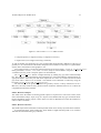
Swarmbot3D User Manual
Giovanni C. Pettinaro
[email protected]
Ivo W. Kwee
[email protected]
Luca M. Gambardella
[email protected]
Technical Report No. IDSIA-22-03
December 16, 2003
IDSIA / USI-SUPSI*
Instituto Dalle Molle di studi sull’ intelligenza artificiale
Galleria 2
CH-6900 Manno, Switzerland
* IDSIA was founded by the Fondazione Dalle Molle per la Qualita della Vita and is affiliated with both the Universita della Svizzera italiana (USI)
and the Scuola unversitaria professionale della Svizzera italiana (SUPSI) in Lugano. This research is funded by European Union and the Swiss
Government under grant 01.0012
Swarmbot3D User Manual
Giovanni C. Pettinaro
[email protected]
Ivo W. Kwee
[email protected]
December 16, 2003
Luca M. Gambardella
[email protected]
Abstract
The present document is the User Manual of the Swarmbot3d simulator. It contains a description of
the software components included in it as well as a the procedure to install the whole package.
A detailed discussion concerning how the simulator’s components have been implemented and concerning the reasons which lead to their implementation are reported in the associated Technical Report
”Definition, Implementation, and Calibration of the Swarmbot3d Simulator”. This document concentrates on the presentation of the application programming interface (API) with which users can design
their own customized robot control. A simple behaviour-based control example is also presentented
and discussed.
Contents
1 Introduction
1.1 About this user manual . . . . . . . . . . . . . . . . . . . . . . . . . . . . . . . . . .
1.2 What is Swarmbot3D? . . . . . . . . . . . . . . . . . . . . . . . . . . . . . . . . . .
1.3 Vortex . . . . . . . . . . . . . . . . . . . . . . . . . . . . . . . . . . . . . . . . . . .
3
3
3
3
2 Setting up Swarmbot3d
2.1 Distribution . . . .
2.2 Requirements . . .
2.3 Setting Up . . . . .
2.4 Vortex License . .
2.5 Verification . . . .
.
.
.
.
.
.
.
.
.
.
.
.
.
.
.
.
.
.
.
.
.
.
.
.
.
.
.
.
.
.
.
.
.
.
.
.
.
.
.
.
.
.
.
.
.
.
.
.
.
.
.
.
.
.
.
.
.
.
.
.
.
.
.
.
.
.
.
.
.
.
.
.
.
.
.
.
.
.
.
.
.
.
.
.
.
.
.
.
.
.
.
.
.
.
.
.
.
.
.
.
.
.
.
.
.
.
.
.
.
.
.
.
.
.
.
.
.
.
.
.
.
.
.
.
.
.
.
.
.
.
.
.
.
.
.
.
.
.
.
.
.
.
.
.
.
.
.
.
.
.
5
5
5
6
6
6
3 Using Swarmbot3d
3.1 Running the simulator . . . . . .
3.1.1 Example Programs . . .
3.1.2 World File . . . . . . .
3.2 Viewer . . . . . . . . . . . . . .
3.2.1 Key Bindings . . . . . .
3.2.2 Mouse interaction . . . .
3.2.3 Graphical user interface
3.3 Python Console . . . . . . . . .
3.3.1 Real-time Interaction . .
3.3.2 Scripting . . . . . . . .
.
.
.
.
.
.
.
.
.
.
.
.
.
.
.
.
.
.
.
.
.
.
.
.
.
.
.
.
.
.
.
.
.
.
.
.
.
.
.
.
.
.
.
.
.
.
.
.
.
.
.
.
.
.
.
.
.
.
.
.
.
.
.
.
.
.
.
.
.
.
.
.
.
.
.
.
.
.
.
.
.
.
.
.
.
.
.
.
.
.
.
.
.
.
.
.
.
.
.
.
.
.
.
.
.
.
.
.
.
.
.
.
.
.
.
.
.
.
.
.
.
.
.
.
.
.
.
.
.
.
.
.
.
.
.
.
.
.
.
.
.
.
.
.
.
.
.
.
.
.
.
.
.
.
.
.
.
.
.
.
.
.
.
.
.
.
.
.
.
.
.
.
.
.
.
.
.
.
.
.
.
.
.
.
.
.
.
.
.
.
.
.
.
.
.
.
.
.
.
.
.
.
.
.
.
.
.
.
.
.
.
.
.
.
.
.
.
.
.
.
.
.
.
.
.
.
.
.
.
.
.
.
.
.
.
.
.
.
.
.
.
.
.
.
.
.
.
.
.
.
.
.
.
.
.
.
.
.
.
.
.
.
.
.
.
.
.
.
.
.
.
.
.
.
.
.
.
.
.
.
.
.
.
.
.
.
.
.
.
.
7
7
7
7
7
8
8
8
9
9
10
4 System Description
4.1 Software Organization . . .
4.1.1 Resources Directory
4.1.2 Source Directory . .
4.2 Reference Models . . . . . .
4.3 Simulator settings . . . . . .
4.4 Threading . . . . . . . . . .
4.5 Performance . . . . . . . . .
.
.
.
.
.
.
.
.
.
.
.
.
.
.
.
.
.
.
.
.
.
.
.
.
.
.
.
.
.
.
.
.
.
.
.
.
.
.
.
.
.
.
.
.
.
.
.
.
.
.
.
.
.
.
.
.
.
.
.
.
.
.
.
.
.
.
.
.
.
.
.
.
.
.
.
.
.
.
.
.
.
.
.
.
.
.
.
.
.
.
.
.
.
.
.
.
.
.
.
.
.
.
.
.
.
.
.
.
.
.
.
.
.
.
.
.
.
.
.
.
.
.
.
.
.
.
.
.
.
.
.
.
.
.
.
.
.
.
.
.
.
.
.
.
.
.
.
.
.
.
.
.
.
.
.
.
.
.
.
.
.
.
.
.
.
.
.
.
.
.
.
.
.
.
.
.
.
.
.
.
.
.
.
.
.
.
.
.
.
.
.
.
.
.
.
.
.
.
.
.
.
.
.
11
11
11
14
16
16
17
18
5 S-Bot Programming
5.1 S-Bot API . . . . . . . . . . . . . . . . . . . . .
5.2 Programming new behaviours . . . . . . . . . .
5.2.1 Example: Behaviour-based programming
5.3 Porting to Hardware . . . . . . . . . . . . . . . .
.
.
.
.
.
.
.
.
.
.
.
.
.
.
.
.
.
.
.
.
.
.
.
.
.
.
.
.
.
.
.
.
.
.
.
.
.
.
.
.
.
.
.
.
.
.
.
.
.
.
.
.
.
.
.
.
.
.
.
.
.
.
.
.
.
.
.
.
.
.
.
.
.
.
.
.
.
.
.
.
19
19
19
19
21
.
.
.
.
.
.
.
.
.
.
.
.
.
.
.
.
.
.
.
.
.
.
.
.
.
.
.
.
.
.
.
.
.
.
.
.
.
.
.
.
.
.
.
.
1
Technical Report No. IDSIA-22-03
A API
A.1
A.2
A.3
A.4
A.5
A.6
A.7
A.8
A.9
A.10
Initialization commands . . . . . . . . . . . . . . . .
Motion commands . . . . . . . . . . . . . . . . . .
Turret commands . . . . . . . . . . . . . . . . . . .
Front gripper commands . . . . . . . . . . . . . . .
Side-arm commands . . . . . . . . . . . . . . . . .
Proximity sensor commands . . . . . . . . . . . . .
Ground sensor commands . . . . . . . . . . . . . . .
Light ring commands . . . . . . . . . . . . . . . . .
Temperature, humidity, and inclinometer commands .
Miscellaneous commands . . . . . . . . . . . . . . .
2
.
.
.
.
.
.
.
.
.
.
.
.
.
.
.
.
.
.
.
.
.
.
.
.
.
.
.
.
.
.
.
.
.
.
.
.
.
.
.
.
.
.
.
.
.
.
.
.
.
.
.
.
.
.
.
.
.
.
.
.
.
.
.
.
.
.
.
.
.
.
.
.
.
.
.
.
.
.
.
.
.
.
.
.
.
.
.
.
.
.
.
.
.
.
.
.
.
.
.
.
.
.
.
.
.
.
.
.
.
.
.
.
.
.
.
.
.
.
.
.
.
.
.
.
.
.
.
.
.
.
.
.
.
.
.
.
.
.
.
.
.
.
.
.
.
.
.
.
.
.
.
.
.
.
.
.
.
.
.
.
.
.
.
.
.
.
.
.
.
.
.
.
.
.
.
.
.
.
.
.
23
23
23
24
25
26
27
27
28
29
30
B Frequently Asked Questions
31
C Known Bugs
33
Chapter 1
Introduction
1.1 About this user manual
This document is intended as a User Manual for the Swarmbot3d simulator. For a more detailed description of the software as well as for maintenance, the reader can refer to the Technical Documentation.
1.2 What is Swarmbot3D?
Swarmbot3d is a package specially designed for simulation and visualization of multiple robots called
s-bots. Each community of s-bots physically linked to each other takes the name of swarm-bot. The
software is able to simulate one single s-bot as well as entities in swarm-bot formation. The simulator
is intended to be used as a virtual test-bed for developing new control algorithms for single or multiple
s-bots, or for investigating how s-bots behave in different environments.
The simulation models provided in Swarmbot3d have been created to match closely the real s-bot
hardware with respect, for instance, to size, mass, and motor torques. Moreover, virtual implementations of most available hardware sensors have been made available to users. Artificial 3D environments
can easily be created either simply by editing configuration files provided in the package, or by defining
them following the outline provided in section 4.1.1.
From the user point of view, Swarmbot3d is able to simulate the behaviour shown by the s-bot
hardware with a very high level of realism and accuracy, a property this which is of much higher
quality than what traditional simulators are currently able to offer.
1.3 Vortex
The core of Swarmbot3d is built on top of a commercially available physics engine Vortex TM 1 which
provides a set of libraries for robust rigid-body dynamics and accurate collision detection. By creating
objects and by linking them with appropriate joints, a user can create very complex mechanical systems.
At each time step, VortexTM calculates the evolution of a system by solving the dynamics problem
involving two kinds of forces: those caused by possible collisions or friction among objects in the
model and those caused by trying to keep the constraints imposed by the joints declared.
VortexTM is well established and has been successfully used in various applications ranging from
vehicle simulation to robotics and evolution of virtual creatures. Its widespread use as well as its
1 This
software is developed and commercialized by CM Labs, Inc. (www.cm-labs.com).
3
Technical Report No. IDSIA-22-03
4
stability, available features, and low price for its academic license were key elements in the decision to
adopt it for this project.
Chapter 2
Setting up Swarmbot3d
2.1 Distribution
Swarmbot3d in its current version 2.2 (CVS tag VERSION 2 2) can be retrieved from its CVS repository in the IDSIA server by issuing the following commands:
$ export CVS_RSH=ssh
$ cvs -d :ext:[email protected]:/ get -r VERSION_2_2 swarm/swarmbot3d_2
The first instructs your CVS client to use the secure shell layer, whereas the second command creates a
new local copy of the sources in your current folder. When the system asks for a password, it is enough
typing anything (but not empty) since downloading is no password controlled.
CVS sources are subject to change quite often, indeed, since any development goes straight into the
software repository, it is advisable to update the local copy on a regular basis. To get the latest release
use ’cvs get’ without the version tag:
$ cvs -d :ext:[email protected]:/ get swarm/swarmbot3d_2
or update your local CVS copy by running the command:
$ cvs update
in the local .../swarmbot 2 folder. Normally, CVS successfully merges new changes automatically
into the local files, however sometimes conflicts are encountered and CVS requires users to resolve
them manually. In such a case, the reader should consult the CVS manual or should freshly download
the full tree as described at the beginning.
2.2 Requirements
As far as the computing hardware is concerned, running Swarmbot3d needs a fairly fast computer. A
fast PC with an accelerated 3D graphics card is strongly recommended. The whole software package
has been developed on a PC with a dual Xeon processor at 1.8 GHz each using one NVidia Quadro2
Pro graphics card.
As a whole, Swarmbot3d (current version 2.2) depends on the following software packages:
• VortexTM 2.1;
• GCC 3.3.2;
5
Technical Report No. IDSIA-22-03
6
• Python 2.3 , python-numeric, python-gnuplot (for the GUI);
• swig 1.3 (to create C++/Python wrappers);
• xlibmesa-glu-dev, libglut-dev, xlibmesa-gl-dev, xlibmesa3-gl, xlibmesa3-glu, libglut3-dev (for
MeViewer).
2.3 Setting Up
After downloading and installing the required packages listed earlier, a user needs to move the swarmbot3d 2
folder exactly under the .../cmltoolkit/src folder, since the makefiles depend on its exact placement relative to the VortexTM distribution.
2.4 Vortex License
Running the VortexTM toolkit requires a valid license issued by Critical Mass Labs, Inc. . The reader
can refer to the VortexTM documentation for its license installation procedure. Without a valid license,
VortexTM disables the collision detection system and although the software appears to run, all objects
fall down through the ground.
In case a node-locked license is not available, the user needs to install a license on a network server.
The local system manager can easily setup it up on a license server. Vortex TM uses FlexLM software
from Macrovision (www.macrovision.com) for license managing.
2.5 Verification
In order to test that everything is working properly, it is advisable trying to compile and run one of the
examples included in the VortexTM distribution, instead of attempting to compile the simulator first. In
this way, it is possible to check whether VortexTM itself and its license are properly set up.
Once VortexTM is up and running, users can go into .../swarmbot3d 2/src directory and compile
there the simulator by issuing the command
$ make release
If the compilation fails, any libraries possibly missing is high-lightened on the output. It is then enough
installing them and retry the compilation.
If the compilation is successful, users should return to the .../swarmbot3d 2 folder and run the
demo program using
$ bin.rel/linux_double/swarmbot3d-null -file Resources/DetailedWorld
This should result into opening two extra windows and a Python shell console on the command line.
The first extra window is the OpenGL window where the simulation is displayed, whereas the second
one is a GUI window with which a user can interact with the robot.
Chapter 3
Using Swarmbot3d
3.1 Running the simulator
3.1.1 Example Programs
Once the demo program has been compiled and run according to the steps described in chapter 2, users
can see that the robots declared in the XML file stay still. This is normal since this demo program does
not contain any control code. There are other examples in the folder .../src/programs which can be
selected instead. To do so, users should recompile the simulator previous a re-editing of the makefile
in .../src. The makefile contains the OUTNAME variable identifying the control program to use during
compilation, and it is enough to replace the name specified there with the one to be used instead.
3.1.2 World File
At execution time, Swarmbot3d loads a description of the 3D world specified in the main XML scene
file. Examples of different scenarios are included in the .../Resources folder and they all have a
*.me extension.
These XML examples are easily editable and customizable to the user needs. For instance, to
increase the number of s-bots to use in a simulation, it is enough to add in the world file the following
XML piece of code:
<ME_FILE>
<ID>s-bot_#</ID>
<NAME>S-Bot/s-bot_detailed.me</NAME>
<POS>25,0,-13</POS>
</ME_FILE>
where in place of # the ID number of the robot has to be filled in. To reduce it, it enough to comment
out similar pieces of XML code, leaving just those accounting for the required number of robots. Be
careful that the robots remain numbered consecutively from zero to the number of total s-bots.
Once the world file is properly edited, users do not need to recompile the simulator: they simply
have to rerun it with the new XML world file.
3.2 Viewer
The Swarmbot3d viewer shows a 3D graphics rendering of the state of the world as computed by
VortexTM . Such a rendering, however, is not strictly necessary to perform a simulation, and can be
7
Technical Report No. IDSIA-22-03
8
easily turned off simply by using the -norender option at the command line. If this option is used, it
is then the responsibility of the user’s control program to show by other means, such as printing final
computations, that the computed simulation is carried out properly.
-norender
3.2.1 Key Bindings
F2 - render mode Choose the rendering mode. Press F2 to toggle between wire-frame and solid rendering. Press Ctrl-F2 to turn on/off alpha blending. Press shift-F2 to toggle texture mapping.
F3 - RTM locking. This key toggles the real-time locking feature of the simulator, its status is shown
in the right-lower area of the viewer; an ’L’ appears if RTM is locked. If locking is on and if
the simulation speed is faster than the requested speed as determined by the real-time multiplier
(RTM), the simulator is artificially forced to slow down to attain the requested RTM value. If the
simulator runs slower than the requested RTM value, RTM locking does not do anything.
F8 - pause. Pause the simulator. Press Ctrl-F8 to resume, or press F8 several times to simulate in single
stepping mode.
m - extra viewer options Pressing this key, displays an on-screen menu of extra visualization options
of joints, center of masses, contacts, etc., which can all be toggled on or off.
3.2.2 Mouse interaction
Users can interact with the simulator’s viewer by using a mouse. By moving it with the left button pressed, the viewing angle of the world changes. By dragging with its middle button, viewing is
zoomed in or out. Finally, by dragging with its right button, the viewing scene is panned horizontally
or vertically.
By moving the mouse while holding down shift+left button, users can pick objects in a scene
and move them around. Static object can be manipulated by using the shift+right button.
moving
mouse
3.2.3 Graphical user interface
The graphical user interface (GUI) is presented as a tabbed window with four panels consisting of:
World panel: In this panel you can set general simulation parameters such as:
1. Time step (ms): this determines the time step taken by the dynamics engine to compute the
next state. A larger value increases simulation speed but it also makes the simulation less
stable. Users should set this value to be as large as possible, however not too high to make
the simulation unstable.
2. Real-time multiplier: this value determines the actual simulator speed in “locked mode”.
Users should set this value to 1 if they wish to simulate “real-time”. Users should bear in
mind, though, to toggle the speed mode to “locked” with function key F3.
3. Frame rate (Hz): this value determines the rendering frequency 1. Users may wish to set this
value as low as possible in order to give to the dynamics time enough for its update and yet
let the simulator’s viewer looks “smooth”.
4. Gravity (cm/s2 ): this value sets the gravity pull to be used. Users should be aware of the fact
that all physical entities within Swarmbot3d are expressed in the centimeter-gram-second
(CGS) system as opposed to the more common meter-kilogram-second (MKS) system. This
1 Notice
that this is independent of the frequency of dynamics update!
world panel
the
Technical Report No. IDSIA-22-03
9
implies that the normal gravity pull at sea level is 981 cm/s2 , hence a mass of 1 g is subjected
to a pull of 981 dyne.
s-bot panel
S-bot panel: This panel provides buttons for controlling the s-bots present in a scene. By pressing
one of them, a separate window opens up providing a real-time control interface for the selected
s-bot. The window is divided into an upper part and lower part. The former contains one button
for reading the robot infrared (IR) proximity sensors, one for reading the light sensors, and finally
three buttons for controlling the light ring. The latter contains on the left a joystick-like command
panel for directly controlling the s-bot motion, whereas on the right three buttons for resetting a
scene, freezing one s-bot, and activating one s-bot. At the bottom right corner, users can find an
input field where the s-bot speed can be set.
Lights panel: This panel sets the values for the ambient light and for a single point light in a scene.
Currently, the VortexTM viewer has the limitation of supporting rendering for only one point light,
nevertheless Swarmbot3d can always handle properly additional points in the light calculations.
lights panel
Ambient light adds a constant contribution to all light sensors in a scene. A point light adds an
intensity contribution to a light sensor proportional to its inverse squared distance.
Users are warned that light sensors of the s-bot can be easily over-saturated. A feature which
stems directly by the kind of sensitive hardware components employed which the software simulator had to comply.
Camera panel: This panel controls a 3D camera which can be used in two ways: as a camera with
which to take snapshots of a scene and as an omni-directional camera located at the top of one sbot. Although all camera movements in principle can be done using a mouse, this panel provides
some buttons for convenience, like zoom in and zoom out, one up button for switching to birdsview, and one track button for tracking the current s-bot position. The number in the “view”slider sets the active s-bot, whereas the special number “-1” designates the current global view.
Users should also notice that covering or resizing the window’s viewer of the simulator with
other windows on the screen causes a snapshot to reflect those cover ups.
3.3 Python Console
The simulator provides an embedded Python interpreter which should appear at the command line
directly after starting the simulator. This interpreter allows a real-time inspection and manipulation of
the objects loaded into a scene. Since Python is an interpreter, it also allows the definition and loading
of user-defined scripts.
For more information about Python, a user is referred to consulting the local documentation or to
reading its tutorials at www.python.org.
3.3.1 Real-time Interaction
Objects in Swarmbot3d are accessible by means of handles provided by the interpreter. These handles
are:
world
A handle to the simulated world. To see a complete list of available commands, type dir(world).
For example, at the Python console, the following commands
>>> world.setAmbientLight(0.1)
>>> world.setTimeStep(0.025)
>>> world.snaphot("snapshot.ppm")
camera panel
Technical Report No. IDSIA-22-03
10
would set the ambient light to 0.1 candela, the simulator time step to 25 ms, and save a snapshot
of the screen (as PPM) to the file snapshot.ppm.
sbot[i]
The standard s-bot API is available as methods to the sbot[i] objects. To see a list of available
commands for one sbot, type dir(sbot[0]). For example at the Python console, the following
commands
>>> sbot[1].setSpeed(10,10)
>>> y = sbot[1].getAllProximitySensors()
result in setting up the speed of left and right wheels of sbot[1] to 10 units and in putting the 15
values of all lateral IR proximity sensors in variable y.
sbot[i].object
The s-bot simulation objects are accessible through these handles and provide “extra” simulator functions which are not in the standard s-bot API, such as resetting the s-bot or accessing
information about its absolute position in the world. For example, the commands
>>> sbot[1].object.sim_gripper_jawed.upperjaw_element.info()
>>> sbot[1].object.getPosition()
>>> sbot[1].object.reset()
would show the simulation state of the StickyElement on the upper jaw of s-bot number 1, get
the robot position in absolute world coordinates, and reset the simulation model to its original
position respectively.
3.3.2 Scripting
Using the embedded interpreter, scripts can be loaded using the Python command
>>> execfile(<script>)
where <script> is the name of a script file. By doing so, users can define a scenario or automate
certain tasks for data collection. Python scripting does not allow to load different worlds, since the
interpreter is killed as soon as the simulator is left. Nevertheless, robots can always be reseted at their
original position and orientation as specified in the world file loaded at command line. In case users
require to make scripts involving different worlds, they need to use shell scripting.
Alternatively, a script file can be specified at start using the command-line option
$ swarmbot3d -script <file> [...]
where <file> is the name of the script. The script will be loaded and run immediately after the
simulator Swarmbot3d is launched.
Chapter 4
System Description
The present chapter provides a full description of the whole simulating package Swarmbot3d. It discusses how it is organized (Section 4.1) and how it emulates robot programs running on the real robot
(Section 4.4).
4.1 Software Organization
The Swarmbot3d simulator is a software built on top of VortexTM , a commercial physics simulation
engine. It is physically installed inside the directory of this last and precisely at the level of its source
code (.../src).
The simulator is organized in two main sub-directories: Resources and src. The former is the
place where all the models and terrains are stored, whereas the latter is the place where the actual
simulator code is kept (Figure 4.1). This section presents each of these components in full detail.
4.1.1 Resources Directory
All models in the simulator are expressed using XML format. To provide a better organization, just
world models loading specific components are kept at this level. All specific parts concerning robot
or terrain models are stored in appropriate sub-directories. Figure 4.2 gives an overview of the entire
structure. Each part is presented and discussed in detail in the following sections.
Folder: Resources/Ground
The XML models stored here define different types of terrain. Those already available are:
• ground plane (a simple flat plane),
Figure 4.1: Global overview of Swarmbot3d directory structure.
11
Technical Report No. IDSIA-22-03
12
Figure 4.2: The overall Resources folder structure.
• composite planes (a rough terrain using a composition of boxes),
• rough terrain (a true rough terrain using a 3D mesh).
As with all models, the declaration of a new ground model should include a definition of the type of
geometry to use, a declaration of the model composition and orientation with respect to a global frame
system, and a customization of the graphics to use.
Concerning geometry, a terrain may be declared using one of two keywords: <PLANE> or <RG HEIGHT FIELD>.
Other geometries (<SPHERE>, <BOX>, and <CYLINDER>) may be used or added to compose a rough environment in the way as the ’composite planes’ has been defined.
The <RG HEIGHT FIELD> defines a height field map by loading any grey-scale 128x128 bitmap
file. The image is first stretched along the rectangular size of the field and then transformed into an
appropriate matrix. Each entry into this matrix represents one vertex on a surface and the associated
grey-scale value is taken to be its altitude. The altitude can be enhanced or reduced by using the
keywords <HEIGHT RANGE> and <RGB MULTIPLIERS>.
The material ID of the ground, regardless the geometry chosen, is always assumed to be zero.
Moreover, the entire model is always declared frozen within the simulated world so as to reduce the
computational load of the simulator.
Folder: Resources/Objects
This folder stores the models concerning specific objects to be placed in a scene such as walls, entire
fence confinements, lamps, slopes, steps, etc. Objects can be defined with any type of material identification depending on their purpose. Some objects can also be defined frozen within the simulator in
order to reduce overheads.
Folder: Resources/Textures
This folder keeps all the textures files in bitmap format which can be used by any model in the simulator.
As mentioned earlier, those bitmap files which define a height field map need to be resized to
128x128 and transformed into grey-scale files.
Technical Report No. IDSIA-22-03
13
Table 4.1: Material codes associated with simulation objects (robot parts and ground).
Simulation Object
ground
external wheels
inner wheels
treels body
turret
front and side arm
front arm gripper lower jaw
front arm gripper upper jaw
side arm gripper lower jaw
side arm gripper upper jaw
Material Code
0
1
2
3
4
5
6
7
8
9
Folder: Resources/Utilities
This folder contains utility files to generate automatically parts of XML files using the PHP hypertext
preprocessor.
Folder: Resources/World
This folder stores world setting files for specific robot models as well as global world settings for all
simulations.
Concerning global settings, users can specify the gravity pull to employ as well as two important
simulation parameters: <EPSILON> and <GAMMA> (see Section 4.3).
Other global world settings concern the contact parameters among the various material pairs present
in the simulated world. Currently, there are 9 different types of material defined and 9 material pairs.
Each material is coded with a number (Table 4.1).
Concerning robot model settings, users can specify within the <USER APPS> environment all the
customizing parameters for an entire simulation or for one type of s-bot and its sensors. There are four
types of parameter keywords recognized by the system:
• <SIMULATION PARAMETERS>,
• <SBOT PARAMETERS>,
• <PROXIMITY SENSOR>, and
• <CAMERA SENSOR>.
Among other customizations, users can here specify the size of the time step to use as well as if a
simulation has to be dumped into a sequence of snapshots.
Folder: Resources/S-Bot
This folder is the place where the definition of all robots are stored. Currently, there are 4 different
XML model files preprogrammed corresponding to the following s-bot reference models:
• Fast model,
• Simple model,
Technical Report No. IDSIA-22-03
14
Figure 4.3: The overall src folder structure.
• Medium model
• Detailed model.
Each of these models is a combination of approximations of the four sub-systems (treels, turret, front
and side arms) with which one s-bot is defined. The creation of a new robot approximation can be done
by loading a different approximation for a specific sub-system within the <ME FILE> environment.
Notice, however, that the Fast model has too different sizes to allow to use parts defined for the higher
level approximations.
Both front and side arm sub-system are defined in a coarse and in a detailed version. The turret
and treels are instead defined in 4 different versions: one for each reference robot. Within the treels
directory, there is a different sub-folder for each type of approximation. The files kept there are the
XML definition of the wheels employed.
4.1.2 Source Directory
This is the part of Swarmbot3d where the actual source code is located. To facilitate future further
development and refinement, the whole package has been divided in 6 sub-directories (Figure 4.1.2
summarizes the whole src directory tree structure):
• behaviours/
• interface/
• programs/
• python/
• simulator/
• util/
The makefile contained here has all the filenames which have to be compiled in Swarmbot3d: if
new files are added, the aforementioned list has to be updated before the simulator is re-compiled.
Among the sub-directories found here, there are two extra ones automatically created and updated
every time the simulator is re-compiled: dependencies/ which holds all the information concerning
the dependencies among all the files and obj.rel/ which stores the actual executable code. Notice in
this regard that in case the simulator is compiled with the debugging flag on, then any executable is not
stored in obj.rel/ but in obj.dbg/.
The following sections describes in full detail the content of all simulator’s sub-folders not automatically created.
Technical Report No. IDSIA-22-03
15
Folder: src/behaviours
This sub-folder stores all the classes implementing specific robot behaviours such as motion, light
following, sensor monitoring, gripping, etc. Classes which define very atomic tasks can be used hierarchically by more complex ones. As an example of such a use, the reader can find in this sub-folder also
the skeleton of a behaviour-based architecture running a low-level random navigation with obstacles
avoidance.
It is important to observe that all behaviours are defined using the same set of instructions available
on the real hardware. This greatly reduces the whole process of porting software from the simulator to
the real robot.
Folder: src/interface
This sub-folder contains two important header files: simulated world.h and real world.h. The
former is meant to make all opportune header inclusions for the simulator and to carry out two tasks:
• starting the main thread for each robot in the simulated world, and
• executing within the main thread the program associated with each robot.
The actual set of robot instructions which makes up the interface is stored in SBot.h (a C++ class)
for the simulator and in sbot.h (standard C) for the real s-bot. A complete list of all these commands
is provided in Appendix A.
Folder: src/programs
This sub-folder stores all the main program which are associated with each simulated robot. The directory provides several simple robot program examples as well as a more complex one making use of
some basic behaviours kept in the behaviours/ sub-folder. Users can define their own control program
by following the program skeleton outlined in swarmbot3d-null.cpp, which shows how to load the
robot interface and an example of behaviour.
An important point to draw attention to is that robot instructions are executed in sequence within
a robot program. This means that, once the last instruction is completed, the execution returns to the
main program and there it rests until either the simulator ends or the robot is ordered to perform other
actions by using the front-end interface.
Folder: src/python
This sub-folder contains all the files written in Python which define the graphic front-end with which
to control one s-bot. To use this graphic user interface (GUI), a robot should not execute any robot program. This means that users should compile the simulator using the swarmbot3d-null.cpp program
file. If an actual control program is loaded, all robots will follow it until it is completed and only then
the control returns back to the main thread and will be available to the front-end interface.
If new features are introduced in the simulator by a developer, then a separate Python compilation has to be carried out in this sub-folder by typing ’make’. This creates the wrapping code that is
necessary to make the C++ methods available through Python. The wrapper generation uses the Swig
(www.swig.org) package.
Folder: src/simulator
This sub-folder is the actual core of the simulating package. It is structured in 5 sub-directories:
controllers which contains the definition of how to thread robot actions,
Technical Report No. IDSIA-22-03
16
devices which stores the low-level implementation of the various actuators and sensors,
modules which holds the definition of all mechanical and sensory modules available in one s-bot,
robots which stores the overall implementation of one s-bot, including the label parsing of the XML
model definitions, and finally
world which implements the general simulation environment using underlying physics engine (Vortex TM).
All simulator initialization and setup is performed here.
Folder: src/util
This last sub-folder keeps all the general purpose utility files such as operations on arrays and non
standard mathematical functions. Users who wish to implement this sort of functions to be used within
future development of Swarmbot3d, should put their definitions in this directory.
4.2 Reference Models
Models can be introduced in the simulator by defining them in the XML format specified in the Vortex TM
user manual. A number of s-bot reference models have been prepackaged with different levels of
abstraction:
• Fast: a most simple abstraction of the s-bot: a miniature robot model in a non-realistic lowgravity simulation environment that allows fast computation.
• Simple: a properly scaled-up version of the previous simple model to approximate hardware
dimensions, and now in a simulated environment with realistic gravity values.
• Medium: a more detailed version of the Simple model, using a 6-wheel locomotion system and
full featured rotating turret.
• Detailed: the most detailed version of the simulated s-bot with teethed wheels and flexible sidearm gripper.
Each of them, however, can always be opportunely customized to accommodate the needs of all users.
This can be achieved by opportunely editing the prepackaged default XML definitions in a different
way. For instance, if it is required, a user can declare define the Medium s-bot model with the detailed
front gripper in place of the coarse one as it is by default.
4.3 Simulator settings
The VortexTM physics engine defines several simulation parameters that affect global simulation accuracy
and speed: <EPSILON>, <GAMMA> and the simulation time step.
Parameter <EPSILON> (defined in the World Settings.me XML file) is used by the physics engine
to solve at every time step the following matrix equation:
(A + εI) · x = b
(4.1)
where A is a positive semi-definite matrix and ε is a scalar value. Degenerate systems have the matrix
A singular, thus if ε would be zero, no solution for that equation could be guaranteed. By providing an
ε scalar value greater than zero, a solution could always be found. It should be noticed that the result of
<EPSILON>
Technical Report No. IDSIA-22-03
17
using ε is the introduction of compliance to the simulated system, this means that everything appears to
be a little bit springy, depending on the size of the scalar value used.
Parameter <GAMMA> (defined in the World Settings.me XML) is used by the physics engine to
correct the updates done to all bodies within a simulation time step. This is important because during
each step the position and velocity of a body is updated based on the force applied to it in that time
step. If no correction is applied, bodies at each joint in a simulated system would soon drift away as the
simulation progresses. A high value for <GAMMA>, however, may yield instability, since too a correction
would be enforced at every time step. An acceptable size for <GAMMA> may be any value which would
make the product between <GAMMA> and time step smaller than 1, and preferably smaller than 0.5. This
parameter has the side effect of determining the level of penetration allowed between two rigid bodies.
The “optimal” values of <EPSILON> and <GAMMA> are very much dependent on other simulation
setting (e.g. sizes, masses, forces, gravity etc.). For the simulation setting of Swarmbot3d values of
<EPSILON>=0.00001 and <GAMMA>=0.1 are used.
Furthermore, the simulation time step (defined in the * Simulation Settings.me XML) used in
Swarmbot3d is set to 10 ms. The Fast model (see Section 4.2), due to the low gravity and low masses,
allows a much greater time step of 100 ms.
These values have been chosen after much experimentation and provided the best trade-off between
stability and speed. Any adjustments of these values must be taken with care.
4.4 Threading
The simulator’s feature discussed here is very important because it explains how Swarmbot3d manages
to emulate programs developed and executed on the real hardware.
To understand the issue, it should be observed that robot programs on the real s-bot are essentially a
sequence of commands written in C language. Some of these commands are so-called “time-extended”,
i.e. after issuing the command it takes some time to complete the action. Such a command is for
example the command to rotate the turret to a certain position. In the hardware, these time-extended
commands are delegated to the low-level PIC controllers.
Notion of these time-extended commands is important given that real robot programs have to take
into consideration the physical time which the mechanics of an action execution implies. For example
after issuing the command to close the gripper, one would need to wait a certain period to make sure
the gripper has closed.
In the simulator however, the problem arises, when multiple simulated s-bots have each separate
control programs, and a time-extended command of single s-bot could block the others from executing
their commands.
To solve this problem, Swarmbot3d makes extensively use of threading at two levels:
1. For each s-bot Swarmbot3d creates a separate simulation thread that each acts as a single instance
of the main() program of the s-bot. Each of these new threads lasts as long as the associated control program is fully carried out. Separate threading ensures that each robot program is running
independently and can act asynchronously with its its hardware and with the environment.
2. For time-extended robot actions, a separate action sub-thread is started to carry it out. Once the
action is completed, the sub-thread is closed and the execution returns to the robot thread. The
result of this process is that time-extended robot actions have to be synchronized by means of
waiting commands; exactly as needs to be done in the real s-bot. Notice that because simulated
time and real time differ, waiting commands in Swarmbot3d have been redefined to correctly
lapse an amount of simulation time that is equivalent time to real time.
<GAMMA>
time step
Technical Report No. IDSIA-22-03
18
By using threading at these two level, Swarmbot3d manages to simulate the program execution on
the real hardware and the very same robot program can be expected to have the same behaviour both
within the simulator and on the real hardware.
4.5 Performance
Depending on the computing hardware onto which Swarmbot3d is run, the use of one type of s-bot
definition may be quite crucial for a efficient simulation. Clearly, the more detailed the robot description
is, the more demanding the simulating software gets. In this respect, it is advised to consider the
appropriate s-bot model (Fast, Simple, Medium or Detailed) for the experiment at hand.
Furthermore, it is strongly advised to run Swarmbot3d on a computer with at least an accelerated
3D graphics card. Without such a hardware element, a computer would not be able to cope even with
the simplest simulation rendering.
For a more detailed analysis of the performance, the interested reader should refer to the “Technical
Documentation” of the simulator. In Appendix B some hints are given to optimize system performance.
Chapter 5
S-Bot Programming
5.1 S-Bot API
Developing controlling software for one s-bot within Swarmbot3d is very easy. Users can in fact define
a new control algorithm by opportunely composing the commands listed in the application user interface
(API). This interface is made of the same commands available on the real hardware, and means that
all programs which are expressed in these terms are portable to the real s-bot without any change; just
some sensor fine tuning may occasionally be required.
A full list of the available commands is reported in Appendix A.
5.2 Programming new behaviours
To define a new robot behaviour, users can act either directly into a MAIN() program or defining it
separately.
To act within the MAIN(), it is enough to take a program such as swarmbot3d-null.cpp, which
is stored in the .../src/program sub-folder, and build a control making direct calls to the robot
commands specified in the API.
To have a more structured way of defining behaviours, users can write them up as separate C++
classes and store them into the .../src/beghaviours sub-folder. By using this second method, one
should include in the control MAIN() program the header of the particular behaviour developed, and
then modify the .../makefile list of .cpp files including the name of the new behaviour. It is then
enough rebuilding the simulator to make the robot act according to the new control.
The following sub-section present the development of a simple behaviour-based control to serve as
an example of robot programming.
5.2.1 Example: Behaviour-based programming
To show how one s-bot can easily be programmed by means of few behaviours, a simple maze is defined
and one robot in its detailed description is considered. The goal is to have it wonder randomly within
such an environment avoiding to bump into walls or other occasional hindrance present in the arena.
The implementation of the control as outlined above, uses four different basic behaviours, each as
a separate class:
• MonitoringProximityBehaviour
• GoBehaviour
19
Technical Report No. IDSIA-22-03
20
• RandomWalkBehaviour
• RunAwayBehaviour
Each behaviour needs to be characterized by three compulsory methods as defined in the abstract
Behaviour class
• takeControl() which establishes if a behaviour needs to be triggered,
• action() which executes whatever a behaviour is supposed to do,
• suppress() which establishes if execution of other behaviours has to be subsumed.
What the control needs to do is to establish a never-ending loop of going ahead and occasionally
interrupt it with a change in course or with an escaping from hindrance. The listing of such a control is
reported here below:
//------------------------------------------------------------------// SIMPLE EXAMPLE DEMO
//------------------------------------------------------------------// Uncomment one of the following world interfaces
#include "interface/simulated_world.h"
//#include "interface/real_world.h"
#include <signal.h>
void outputError(const char *error) {
fprintf(stderr,"%s\n",error);
}
void sigHandler(int s) {
//setSpeed(0,0);
//shutdownSwarmBot();
exit(0);
}
#include
#include
#include
#include
"behaviours/MonitoringProximityBehaviour.h"
"behaviours/GoBehaviour.h"
"behaviours/RandomWalkBehaviour.h"
"behaviours/RunAwayBehaviour.h"
#include "util/ArrayUtils.h"
int MAIN()
{
signal(SIGTERM, sigHandler);
signal(SIGINT, sigHandler);
initSwarmBot(outputError, outputError);
MonitoringProximityBehaviour monitor(SELF);
GoBehaviour
go(&monitor,SELF);
RandomWalkBehaviour
randomWalk(SELF);
Technical Report No. IDSIA-22-03
RunAwayBehaviour
21
runAway(&monitor,SELF);
// Now wander endelessly in a random fashion
while(1) {
int gotakecontrol = go.takeControl();
int randomwalksuppress = randomWalk.suppress();
int runawaysuppress = runAway.suppress();
if (gotakecontrol && !randomwalksuppress && !runawaysuppress)
go.action();
else
if (randomwalksuppress && !runawaysuppress)
randomWalk.action();
else
if (runawaysuppress)
runAway.action();
}
// In the simulated sbot, this does nothing
shutdownSwarmBot();
}
It is important to point out that behaviours cannot see directly the interface. This needs to be
included in their header declaration, in order to be able to use it in the definition of their action()
method.
5.3 Porting to Hardware
This is an important point concerning software. It is well known that porting software from a simulated
world to reality is usually a very time-consuming job and often requires considerable change in the
programs. Swarmbot3d overcomes this by enforcing the use of a common API with the hardware.
As long as users stick to the API, simply commenting the line including simulated world.h file and
commenting out the line including real world.h file will port the program to allow compilation for
the hardware s-bot. The simulator allows to go beyond the API, however this is strongly discouraged
since porting is then not guaranteed anymore.
Technical Report No. IDSIA-22-03
22
Acknowledgments
The work presented here is part of the SWARM-BOTS project, which is funded by the Future and
Emerging Technologies programme (IST-FET) of the European Community under grant IST-200031010 and by the Swiss Government under grant 01.0012.
The information provided is the sole responsibility of the authors and does not reflect the Community’s opinion. The Community is not responsible for any use that might be made of data published
here.
Appendix A
API
This appendix lists the functions that are defined as the common application programming interface
(API) for both the real hardware s-bot and the simulated s-bot. The interface in the hardware s-bot use
standard C (defined in interface/sbot.h). The simulator uses an equivalent C++ interface (defined
in interface/SBot.h) and implements this interface in the class simulator/robots/VirtualSBot.
A.1
Initialization commands
void initSwarmBot(void (*errorHandler)(const char *errorString),
void (*warningHandler)(const char *warningString));
This command initializes the selected s-bot. On the real hardware, it has the effect of
requesting the I2C low level interface and of setting up the default values. Within the
simulator all initialization have already been carried out, thus this command has no effect.
It is anyhow retained since the real hardware requires it.
It takes two arguments: one call-back function to handle errors (critical problem) and one
to handle warnings (non-critical problem).
errorHandler This is a pointer to the error function which takes the string describing the
error in argument.
warningHandler This is a pointer to the warning function which takes the string describing
the warning in argument.
void shutdownSwarmBot(void);
This command shuts down the selected s-bot. On the real robot, it has the effect of freeing
the low level interfaces to I2C. Within the simulator it has no effect, since shutting down is
performed automatically when users quit the simulating environment.
A.2
Motion commands
void setSpeed(int left, int right);
This command sets the speed of the robot tracks. It has the same effect both on the real
hardware and on the simulated s-bot.
It takes two arguments:
23
Technical Report No. IDSIA-22-03
left Left motor speed.
right Right motor speed.
Both left and right can be any integer values within the range [-127;127]. Notice, however,
that because of physical limits of the motor torques, the maximum speed a real s-bot can
reach is no more than 200 mm/s. Since a speed unit correspond to 2.8 mm/s, the maximum
speed reachable is equivalent to about 70 units. With the real hardware the robot speed
is software limited at 90 units, although users should never use speeds higher than 70.
Because of this speed is software limited at 70 units within Swarmbot3d.
void getSpeed(int *left, int *right);
This command reads the current speed of each track.
It takes two arguments:
left Left motor speed pointer.
right Right motor speed pointer.
The values returned by these reading are within the range of [-127;127].
void getTrackTorque(int *left, int *right);
This command reads the current torque of each track.
It takes two arguments:
left Left track torque pointer.
right Right track torque pointer.
The values returned by these reading are within the range of [-127;127].
A.3
Turret commands
void setTurretRotation(int pos);
This command drives the upper part (turret) of one s-bot for the specified angle about the
robot central vertical axis. The maximum turret rotation a real s-bot is able to carry out
clockwise or counter-clockwise corresponds to 200◦. Since units are expressed in units
within the range of [-100;100], each unit is equivalent to 2◦ .
The command takes one argument only:
pos Angle of rotation.
int getTurretRotation(void);
This command reads the angle about which the s-bot turret has rotated with respect to the
default zero rotation. This particular position corresponds to the robot turret aligned with
the underlying treels and with its front gripper right on top of ground sensor 0.
It does not take any argument but it returns the turret rotation angle in units within the
range of [-100;100].
int getTurretRotationTorque(void);
This command reads the rotation torque of the robot turret.
It does not take any argument and it returns an integer within the range of [-127;127]
expressing the torque read.
24
Technical Report No. IDSIA-22-03
A.4
Front gripper commands
void setGripperElevation(int elevation);
This command sets the elevation of the robot front gripper arm expressed in sexagesimal
degrees.
It takes one argument:
elevation Angle of elevation in degrees.
Because of physical constraints, the real gripper arm elevation is limited within the range
of [-90;90]. Within Swarmbot3d any value outside such a range is automatically cut to the
nearest end. This means, for instance, that requesting an elevation of 100 ◦ would result in
stopping the arm actuation as soon as 90◦ is reached.
int getGripperElevation(void);
This command reads the current gripper arm elevation with respect to the zero elevation
which occurs when arm and turret are aligned.
It does not take any argument but it returns an integer within the range of [-90;90].
void setGripperAperture(int aperture);
This command sets the aperture of the front gripper arm jaws. The value specified corresponds to the sexagesimal angle between one jaw and the front arm central axis.
It takes one argument:
aperture Angle of aperture in degrees.
The maximum angle a real jaw can reach is 45◦ . This means that the maximum bite width
reachable is 90◦ . Hence, aperture can be any integer within the range of [0;45].
int getGripperAperture(void);
This command reads the current elevation of one front gripper arm jaw, which doubled
becomes the overall aperture of the gripper.
It does not take any argument and it returns an integer within the range of [0;45].
int getGripperElevationTorque(void);
This command reads the gripper torque.
It does not take any argument and it returns a value within the range of [-127;127].
void getGripperOpticalBarrier(unsigned *internal,
unsigned *external,
unsigned *combined);
This command reads the optical barrier of the front gripper arm. The readings are within
the range of [0;700] with 0 representing total obstruction and 700 representing open empty
gripper.
It does not take any input parameter, but it returns three values:
internal This is a pointer to the reading representing the internal barrier sensor.
external This is a pointer to the reading representing the external barrier sensor.
combined This is a pointer to the reading representing the internal and external combined
barrier sensor reading.
25
Technical Report No. IDSIA-22-03
A.5
Side-arm commands
void setSideArmPos(int elevation, int rotation, int depth);
This command positions the flexible side arm in space by setting the elevation and rotation angle of the main side arm axis, and by setting the outward/inward depth it has to
protrude/retract, respectively.
It takes three input parameters:
elevation This represents the tilting angle in sexagesimal degrees with respect to the horizontal flexible arm resting position.
rotation This represents the rotating angle in sexagesimal degrees with respect to the flexible arm resting position which is 110◦ from the front gripper arm main axis.
depth This is the depth to which the gripper at the end tip of the arm has to be protruded
or retracted.
void getSideArmPos(int *elevation, int *rotation, int *depth);
This command reads the current position of the flexible side arm.
It does not take any input parameters but it returns three values:
elevation Tilting angle of the arm main axis with respect to the horizontal rest position.
rotation Rotating angle of the main axis with respect to the resting position (110 ◦from the
front gripper arm main axis).
depth Protruding or retracting depth to which the gripper of the flexible arm has to be
located.
void getSideArmTorque(int *elevation, int *rotation, int *depth);
This command reads the current torque which the flexible arm motors are subjected.
It takes no input parameters and it returns three values:
elevation This is a pointer to the torque reading of the elevating actuator.
rotation This is a pointer to the average torque reading of the actuators performing horizontal rotations.
depth This is a pointer to the difference between the torque of the actuators performing
horizontal actuation.
void setSideArmOpened(void);
This command actuates the side arm gripper so as to open up completely its jaws.
It does not take any input parameters nor returns any value.
void setSideArmClosed(void);
This command actuates the side arm gripper so as to close completely its jaws.
It does not take any parameters, nor returns anything.
void getSideArmOpticalBarrier(unsigned *internal,
unsigned *external,
unsigned *combined);
26
Technical Report No. IDSIA-22-03
This command reads the optical barrier of the flexible gripper arm. The readings are within
the range of [0;700] with 0 representing total obstruction and 700 representing open empty
gripper.
It does not take any input parameters and it returns three values:
internal This is a pointer to the reading representing the internal optical barrier sensor
reading.
external This is a pointer to the reading representing external optical barrier sensor reading.
combined This is a pointer to the reading representing the internal and external combined
optical barrier sensor reading.
A.6
Proximity sensor commands
unsigned getProximitySensor(unsigned sensor);
This command reads the current value of the specified IR proximity sensor.
It takes one input parameter and it returns one unsigned integer encoding the distance to
the hit target within the range of [0;8191]:
sensor IR labelling number within the range of [0;14].
The distance encoded is not linearly proportional to the actual distance. One object 150
mm away produces a reading of 20, another one at 50 mm away induces a reading of 50, yet
another one at 10 mm produces a reading of 1000, and finally one at 5 mm away produces
a reading of 3700.
void getAllProximitySensors(unsigned sensors[15]);
This command reads the value of all IR proximity sensors and dumps them into an array.
All readings are within the range of [0;8191].
It does not take input parameters but it returns its readings in an array of 15 locations:
sensors Array of distances to objects.
void setProximitySamplingRate(SamplingRate rate);
This command sets the IR proximity sensor sampling rate.
It takes one input parameter:
rate Sampling rate expressed in terms of SAMPLING RATE xx values.
A.7
Ground sensor commands
unsigned getGroundSensor(unsigned sensor);
This command reads the value of one of the specified ground sensor.
It takes one input parameter and it returns one unsigned integer within the range of [0;255]:
sensor Ground IR sensor number within the range of [0;3].
27
Technical Report No. IDSIA-22-03
The distance to the ground encoded in the reading of one ground IR sensor is not linearly
proportional to the actual distance. A ground 6 mm away provides a reading of 1, one at 2
mm produces a reading of 25, and one at 1 mm distance generates a reading of 100.
void getAllGroundSensors(unsigned sensors[4]);
This command reads the value of all ground sensors and dumps them into an array of 4
elements.
It takes no input parameters and it returns the ground sensor readings into the specified
array:
sensors Array of distances to objects.
void setGroundSamplingRate(SamplingRate rate);
This command sets the sampling rate of the IR ground sensors.
It takes one input parameter and it does not return anything:
rate Sampling rate expressed in terms of SAMPLING RATE xx values.
A.8
Light ring commands
unsigned getLightSensor(unsigned sensor);
This command reads the value of the specified light sensor within the range of [0;700] with
0 representing full darkness and 700 representing full light.
It takes one input parameter and it returns one unsigned integer:
sensor Light sensor number within the range of [0;7].
void getAllLightSensors(unsigned sensors[8]);
This command reads the value of all light sensors and dumps them into one array of 8
elements.
It takes no input parameters and it returns one array of unsigned integers:
sensor Array of light intensities.
void setLightColor(unsigned light,
unsigned r,
unsigned g,
unsigned b,
BlinkingRate blink);
This command sets the color of a light emitter with a specified blinking rate.
It takes 5 input parameters and it does not return anything:
light Light sensor number within the range of [0;7].
r Red light intensity within the range of [0;15].
g Green light intensity within the range of [0;15].
28
Technical Report No. IDSIA-22-03
b Blue light intensity within the range of [0;15].
blink Blinking rate expressed in terms of BLINKING RATE xx values.
void setAllLightColor(unsigned r[8],
unsigned g[8],
unsigned b[8],
BlinkingRate blink[8]);
This command sets the color of all light emitters.
It takes 4 input parameters and it returns nothing:
r Array of red light intensities with each value expressed within the range of [0;15].
g Array of green light intensities with each value expressed within the range of [0;15].
b Array of blue light intensities with each value expressed within the range of [0;15].
blink Array of blinking rates with each value expressed in terms of BLINKING RATE xx
values.
void setSameLightColor(unsigned r,
unsigned g,
unsigned b,
BlinkingRate blink);
This command sets the same color for all light emitters.
It takes 4 input parameters and it returns nothing:
r Red light intensity expressed within the range of [0;15].
g Green light intensity expressed within the range of [0;15].
b Blue light intensity expressed within the range of [0;15].
blink Blinking rate expressed in terms of BLINKING RATE xx values .
void setLightSamplingRate(SamplingRate rate);
This command sets the sampling rate of the light sensors.
It takes one input parameter and it returns nothing:
rate Sampling rate expressed in terms of SAMPLING RATE xx values.
A.9
Temperature, humidity, and inclinometer commands
void getTemperatureAndHumidityLeft(float *temperature, float *humidity);
This command in case of the real s-bot reads the left temperature and humidity sensors.
Such a command is currently not implemented in the simulated s-bot, thus its use has no
effect within Swarmbot3d.
It takes no input parameters and it returns two values:
temperature Pointer to the reading of the current sensed temperature expressed in degree
Celsius within the range of [-40;123].
29
Technical Report No. IDSIA-22-03
humidity Pointer to the relative humidity reading within the range of [0;100].
void getTemperatureAndHumidityRight(float *temperature, float *humidity);
This command in case of the real s-bot reads the right temperature and humidity sensors.
Such a command is currently not implemented in the simulated s-bot, thus its use has no
effect within Swarmbot3d.
It takes no input parameters and it returns two values:
temperature Pointer to the reading of the current sensed temperature expressed in degree
Celsius within the range of [-40;123].
humidity Pointer to the relative humidity reading within the range of [0;100].
void getSlope(int *pitch, int *roll);
This command reads the slope pitch and roll angles of a robot.
It takes no input parameters and it returns two values:
pitch Pointer to the pitch angle expressed within the range of [-180;180].
roll Pointer to the roll angle expressed within the range of [-180;180].
void setSlopeSamplingRate(SamplingRate rate);
This command sets the sampling rate of the slope sensor.
It takes one input parameters and it does not return anything:
rate Sampling rate expressed in terms of SAMPLING RATE xx values.
A.10 Miscellaneous commands
unsigned getBatteryVoltage(void);
This command in case of the real s-bot has the effect of providing the current battery voltage expressed in Volts. Such a command is not currently implemented within Swarmbot3d,
thus its use has no effect at the moment.
It takes no input parameters and it returns one unsigned integer within the range of [0;255]
encoding the current potential available from the batteries. A reading of 0 corresponds to
0 Volts and a reading of 255 corresponds to 10 Volts.
void playMusic(const char *filename);
This command plays the sound specified in filename.
It takes one input parameter and it does not return anything:
filename String of characters representing the music file name.
void stopMusic(void);
This command has the effect of simply stopping emitting any music being played. In case
no music file is being played, the command has no effect.
It does not take input parameters and it returns nothing.
30
Appendix B
Frequently Asked Questions
Do I really need a dual processor? While the core Vortex dynamics engine does not (yet) support
multi-threading, the s-bot control programs and several other lower level routines run in separate
threads and can therefore draw advantage from multiple processors. It is (as an experimental
feature) also possible to compile the graphics rendering in a separate thread, this is not done as
default because on single processor machines render threading has been reported to slow down.
Some objects are missing in the world! The XML parser is very strict and any errors in the XML file
will mostly result in disregarding the remaining part of the file: the world seems to have loaded
correctly but in fact some objects or parameters have not been parsed. Most common errors are
due to non-matched HTML tags. Carefully read the error messages and check the XML file. The
debug version may provide more detailed error messages.
The simulator is so slow! How can I speed up the simulation? Dynamics simulation and 3D visualization are computation intensive, so the first utmost requirements are a fast computer and good
graphics card. However, there are a few tricks to further optimize simulation speed.
First, determine the bottle neck by looking at the performance bar at the bottom of the viewer.
Most probably either the dynamics or rendering part will be much greater compared to the others.
If dynamics (red part) is the bottle neck:
• Increase the time step: However be careful, a time step too large will make the simulation
unstable.
• Use simpler s-bot model: Switch to a simpler s-bot model according to your needs.
In case the rendering (green part) is the bottle neck:
• Decrease render frame rate: You can decrease the rendering frame rate by either using the
GUI controls, or in using the function setFrameRate(int hz). Decreasing the rendering
frequency leaves more time to the dynamics engine, so simulation progresses faster.
• Simplify rendering: Avoid using spheres as they require many polygons to draw. Try turning
off using textures using -notextures.
• Use a flat plane or smaller terrain size: The rendering of the rough terrain requires much
of the renderer. Use either a single flat plane, or decrease the terrain size in the XML.
• Turn-off rendering: turn off rendering using the option -norender.
31
Technical Report No. IDSIA-22-03
32
I don’t need the viewer. For off-line simulation you can turn off the rendering using the -norender
option. This is useful need to do many simulations. You can still use the Python interpreter and
scripting (using the -script option) to schedule actions during simulation, like collecting and
saving data.
I don’t need Python. You can turn off the Python interpreter completely using the -nopyhthon option. If you don’t want to compile Python
I don’t have Python. You can disable compilation of the Python related code by unsetting the PYTHONSHELL
definition at the top of .../src/simulator/VortexWorld.cpp. However, you need to recompile the source after this change.
Appendix C
Known Bugs
Command line echo disappears after quitting Swarmbot3d.
At some terminals it has been noted that terminal echoing disappears after quitting the simulator.
This seems only to happen if the Python console has been used. Either disable Python using the
option -nopython or quit the terminal. It has been noticed that the Emacs built-in shell does not
suffer from this.
Simulator child-processes not killed properly.
Sometimes, especially when the simulator is terminated by force, child-processes in the background are not killed properly together and these “ghost processes” will result in an overall decrease in system performance. The user needs to kill the processes manually. The best way to
terminate the swarmbot3D is to close the OpenGL viewer window using the ’ESC’-key, or issue
the command quit() on the Python console.
Simulator bodies ’explode’ when picking with the mouse.
Picking objects with the mouse by dragging the object while pressing <shift + leftMouseButton>
results sometimes in instability causing the object to ’explode’. It is noticed that it may be related
to incorrect values of the moments of inertia of the objects. It seems that especially cylinder
geometry exhibit this behaviour. Try to pick on a different part of the s-bot, e.g. the tracks body.
Newer versions of Vortex seems to have improved stability.
33