1
DiviSuite
User’s Manual
DiviSuite 1.2
TABLE OF CONTENTS
1
2
3
Introduction .......................................................................................................................................................... 5
1.1
Product Overview ............................................................................................................................................ 5
1.2
PC/Laptop minimum requirements ................................................................................................................... 5
Product Features ................................................................................................................................................... 6
2.1
DiviSuite Basic ................................................................................................................................................. 6
2.2
RF Scope Plugin................................................................................................................................................ 6
2.3
TS Analyzer Plugin............................................................................................................................................ 7
2.4
T2-MI Analyzer Plugin ...................................................................................................................................... 7
2.5
Supported Devices ........................................................................................................................................... 7
Installing DiviSuite ................................................................................................................................................. 9
3.1
4
3.1.1
DiviSuite installer .....................................................................................................................................9
3.1.2
Installation ..............................................................................................................................................9
3.2
Plugin activation ............................................................................................................................................ 12
3.3
Calibration File activation .............................................................................................................................. 12
3.4
Connect your device ....................................................................................................................................... 12
Starting with DiviSuite ........................................................................................................................................... 13
4.1
5
Software installation ........................................................................................................................................ 9
DiviSuite startup ............................................................................................................................................ 13
DiviSuite Basic Graphical User Interface................................................................................................................. 14
5.1
DiviSuite main window................................................................................................................................... 14
5.2
Menu Panel ................................................................................................................................................... 15
5.3
Status Bar Panel............................................................................................................................................. 15
5.4
Status Bar Panel: Device Status ...................................................................................................................... 16
5.5
Status Bar Panel: Analysis Controls................................................................................................................. 17
5.5.1
Overview ............................................................................................................................................... 17
5.5.2
Input start ............................................................................................................................................. 17
5.5.3
Record input stream .............................................................................................................................. 18
5.5.4
Video display ......................................................................................................................................... 20
5.5.5
IP Forward ............................................................................................................................................. 21
5.6
Input Statistics ............................................................................................................................................... 23
5.7
Monitoring View Control ................................................................................................................................ 24
5.8
Context Panel................................................................................................................................................. 25
5.9
Context View: About ...................................................................................................................................... 25
5.9.1
Software Information............................................................................................................................. 25
5.9.2
Device Management.............................................................................................................................. 26
DiviSuite 1.2 - User's Manual
2 / 66
5.9.3
Plugin activation .................................................................................................................................... 26
5.9.4
Calibration activation ............................................................................................................................. 26
5.10 Device Config View ........................................................................................................................................ 27
5.10.1
Overview .......................................................................................................................................... 27
5.10.2
Connect a device ............................................................................................................................... 28
5.10.3
Select device mode ........................................................................................................................... 29
5.10.4
Device Information............................................................................................................................ 30
5.10.5
Device Plugins ................................................................................................................................... 30
5.10.6
Input Selection and Configuration ..................................................................................................... 31
5.10.7
Output Selection and Configuration................................................................................................... 37
5.11 Settings view ................................................................................................................................................. 39
5.11.1
Validation of a setting........................................................................................................................ 40
5.11.2
Activation and log of an alarm ........................................................................................................... 40
5.11.3
Bitrate setting ................................................................................................................................... 41
5.11.4
Log setting ........................................................................................................................................ 42
5.11.5
DiviSuite setting ................................................................................................................................ 42
5.12 Monitoring View ............................................................................................................................................ 43
5.12.1
Overview .......................................................................................................................................... 43
5.12.2
Stream Tree View in DVB-T2 .............................................................................................................. 44
5.12.3
Stream Tree View in DVB-T ................................................................................................................ 45
5.12.4
Stream Tree View tools...................................................................................................................... 46
5.12.5
Logs View.......................................................................................................................................... 46
5.12.6
Monitoring Windows ........................................................................................................................ 46
5.12.7
Alarm Monitoring Window ................................................................................................................ 49
5.12.8
Log Monitoring Window.................................................................................................................... 50
5.12.9
Bitrate Monitoring View .................................................................................................................... 50
5.13 Profile management ...................................................................................................................................... 51
6
RF Scope plugin ..................................................................................................................................................... 52
6.1
Settings Panel ................................................................................................................................................ 52
6.2
RFScope Monitoring view ............................................................................................................................... 53
6.2.1
Monitoring views................................................................................................................................... 55
6.2.2
Echoes Pattern (Channel Impulse Response) .......................................................................................... 56
6.2.3
Constellation ......................................................................................................................................... 57
6.3
7
Report File ..................................................................................................................................................... 58
6.3.1
File Segment Configuration .................................................................................................................... 58
6.3.2
Report Configuration ............................................................................................................................. 58
TS Analyzer plugin ................................................................................................................................................. 59
7.1
Setting Panel ................................................................................................................................................. 59
DiviSuite 1.2 - User's Manual
3 / 66
7.1.1
Table settings......................................................................................................................................... 59
7.1.2
ETR 290 Settings .................................................................................................................................... 60
7.2
8
TS Analyzer Monitoring view .......................................................................................................................... 61
T2MI Analyzer plugin ............................................................................................................................................. 62
8.1
Setting Panel ................................................................................................................................................. 62
8.2
T2MI Analyzer Monitoring view...................................................................................................................... 63
9
Equipment return for repair................................................................................................................................... 64
10
Upgrades and Privileged Area ................................................................................................................................ 65
11
Contact Information .............................................................................................................................................. 66
DiviSuite 1.2 - User's Manual
4 / 66
1 Introduction
This User’s Manual applies for DiviSuite 1.2 software. This manual includes general
information about DiviSuite software, installation instruction and operating instructions.
For installation instruction of the ENENSYS’ device delivered with the DiviSuite, please
refer to the User’s Manual of this device.
1.1 Product Overview
DiviSuite software is ENENSYS’ analysis tool for analyzing RF parameters down to
Video of Digital TV signals. It allows analysis and monitoring of RF and baseband
signals and supports MPEG2-TS, DVB, ATSC and ISDB standards. It also features
real-time capture and offline analysis as well as video decoding.
In order to receive the signal, DiviSuite need to be connected to an ENENSYS’ USB
adapter. Depending on this device, different interface and standards will be managed:
RF, ASI, IP, File interface
DVB-T2, DVB-T, DVB-C, DTMB, ATSC, ISDB standards…
Please, refer to §2.5 for a list of available devices.
DiviSuite is composed of DiviSuite Basic which can be enhanced by plugin activation.
Available plugins are RF monitoring (RFScope plugin), MPEG2-TS analysis (TS Analyzer
plugin) and T2-MI analysis (T2-MI Analyzer Plugin).
1.2 PC/Laptop minimum requirements
In order to ensure best performances, DiviSuite should be installed on a computer with
at least a Dual-Core processor, 2GHz and 1GB of RAM.
DiviSuite 1.2 - User's Manual
5 / 66
2 Product Features
2.1 DiviSuite Basic
DiviSuite Basic allows reception of a Digital TV stream from RF or baseband though the
adapter interface (RF front end, ASI or IP). This stream can be recorded in real-time in
a file for offline play out. DiviSuite Basic also allows monitoring of PIDs’ bitrate. Alarm
management is embedded as well as log file management to ease monitoring of
signals.
DiviSuite Basic features real-time decoding of audio and video contents of the incoming
stream. It supports standard SD and HD format (as well as specific standards) encoded
in MPEG-1/2, MPEG4 ASP, MPEG4 AVC (H.264) …
DiviSuite Basic can be enhanced through activation of its plugins:
RF Scope: RF Signal Quality monitoring
TS Analyzer: MPEG2-TS analysis
T2-MI Analyzer: DVB-T2 T2-MI analysis.
However, DiviSuite Basic already allows reception of RF signals even if RFScope is not
activated. T2-MI stream reception is also possible without T2MI Analyzer plugin. In this
case, it is possible to display and record the content.
2.2 RF Scope Plugin
RF Scope plugin is the RF Signal Quality Monitoring feature of DiviSuite. It allows
monitoring, in real-time, the RF parameters of the incoming signal1:
Demodulation status (front end lock …)
Signal Level, SNR (signal to noise ration), MER (Modulation Error Rate)
Impulse Response (echoes)
Bit error rates: LDPC iteration and BCH BER in DVB-T2, Viterbi and RS in DVB-T
Constellation graph
Modulation parameters: L1 signaling in DVB-T2 (PLP modulations parameters,
…), TPS information in DVB-T
1
Available RF parameters and accuracy of the measurements depend on the RF adapter used, not on the DiviSuite
software. Please, refer to your RF adapter datasheet for more information.
DiviSuite 1.2 - User's Manual
6 / 66
2.3 TS Analyzer Plugin
TS Analyzer plugin is the analysis tool for MPEG2 Transport Stream. TS Analyzer plugin
allows parsing stream content by decoding System Information (SI) tables. Stream can
be parsed by tables (PAT, PMT, EIT…) and by services in addition to PID parsing feature
of the DiviSuite Basic application. It also provides analysis tools for MPEG2-TS
consistency checking as defined by ETSI TR 101 290 (aka ETR 290).
Table parsing supports all standard based on MPEG2-TS: raw MPEG2-TS (PAT, PMT),
DVB, ATSC and ISDB. It also features private tables and section decoding through
configurable scripts. Content parsing is also made easier thanks to DiviSuite search tool
which allows searching for a specific pattern (label, value …) in the content of the
stream.
ETR290 analysis features ETSI TR 101 290. It supports Level 1, 2 and 3. It features
configurable alarms (parameter checking activation and threshold) that can be logged.
PCR accuracy measurements are also available, providing real-time value display as
well as history graph and PCR accuracy density graph. All ETR290 analysis can be done
on specific PID or a service.
2.4 T2-MI Analyzer Plugin
T2-MI Analyzer plugin is the analysis tool for DVB-T2 Modulator Interface monitoring. It
supports T2-MI Single and Multi-PLP streams. It allows real-time monitoring of DVB-T2
parameters and de multiplexing of PLP contents. These contents can then be analyzed
in real-time with TS Analyzer plugin, decoded and displayed…
T2-MI monitoring features T2-MI parsing, T2 Frame analysis (T2 Superframe, T2 frame
composition, BB frames…), L1 decoding (L1 pre and post, PLP modulation
parameters…) and T2-MI timestamps analysis.
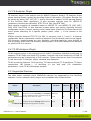
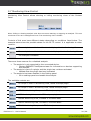
2.5 Supported Devices
DVB-T/T2 Measurement Receiver.
Standard
DVB-T/T2
ReFeree T2 allows recording and analyzing MPEG2-TS
of RF or baseband DVB-T and DVB-T2 signals
T2-MI
ReFeree T2 through its RF, ASI or IP input.
USB2.0 to ASI adapter.
DiviPitch ASI allows playing MPEG2-TS and
DiviPitch ASI T2MI files through ASI or IP output.
DiviSuite 1.2 - User's Manual
Interfaces
RF, ASI
IP
T2MI
Analyzer
Description
TS
Analyzer
Device
RFScope
The table below indicates which ENENSYS’s devices are supported by the DiviSuite
software. It also indicates which plugins are compatible with these devices.
File
MPEG2-TS
ASI
T2-MI
IP
File
7 / 66
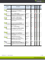
ASI to USB2.0 adapter.
DiviCatch ASI allows recording and
DiviCatch ASI analyzing MPEG2-TS and T2MI files through
ASI or IP output.
ASI <-> USB2.0 adapter.
DiviDual ASI allows playing, recording and
DiviDual ASI analyzing MPEG2-TS and T2MI streams
through ASI or IP input and output.
SPI/LVDS <-> USB2.0 adapter.
DiviDual ASI+LVDS allows playing,
DiviDual ASI+LVDS recording and analyzing MPEG2-TS and
T2MI streams through SPI/LVDS, ASI or IP
input and output.
SPI/TTL<-> USB2.0 adapter.
DiviDual ASI+LVDS allows playing,
DiviDual ASI+TTL recording and analyzing MPEG2-TS and
T2MI streams through SPI/TTL, ASI or IP
input and output.
ASI <-> USB2.0 adapter.
DiviDual T2MI allows playing, recording
DiviDual T2MI and analyzing MPEG2-TS and T2MI files
through ASI or IP input and output.
Interfaces
MPEG2-TS
ASI
T2-MI
IP
T2MI
Analyzer
Standard
TS
Analyzer
Description
RFScope
Device
File
MPEG2-TS
ASI
T2-MI
IP
File
MPEG2-TS
T2-MI
SPI/LVDS,
ASI
IP
File
MPEG2-TS
T2-MI
SPI/TTL,
ASI
IP
File
MPEG2-TS
ASI
T2-MI
IP
File
TS Analyzer and T2MI are included in the bundle
DVB-T professional receiver
DiviCatch RF-T allows recoding and
DiviCatch RF-T analyzing RF DVB-T signals. It also
supports MPEG2-TS and T2-MI files through
ASI or IP input.
QAM professional receiver
DiviCatch RF-C allows recoding and
DiviCatch RF-C analyzing RF DVB-C Annex A, B and C
signals. It also supports MPEG2-TS and T2MI files through ASI or IP input.
DTMB professional receiver
DiviCatch RF-DTMB allows recoding and
analyzing RF DTMB signals. It also supports
DiviCatch RF-DTMB MPEG2-TS and T2-MI files through ASI or IP
input.
DiviSuite 1.2 - User's Manual
DVB-T
RF, ASI
MPEG2-TS
IP
T2-MI
File
DVB-C Annex
A, B & C
RF, ASI
MPEG2-TS
IP
File
T2-MI
DTMB
RF, ASI
MPEG2-TS
IP
T2-MI
File
8 / 66
3 Installing DiviSuite
3.1 Software installation
3.1.1 DiviSuite installer
The software for installing the DiviSuite is stored on the USB key delivered with your
ENENSYS device. It can be found in the same section of the readmefile.html as this
manual, click on the icon
You can also download the latest release from the ENENSYS privileged area website
(http://privileged.enensys.com). ENENSYS releases product updates which include new
available features on its privileged area. Those updates are announced to users
registered on the mailing list. We highly recommend registering yourself on the
mailing list in order to be informed of the latest product release.
The DiviSuite software supports Windows XP, Windows Vista and Windows 7 operating
systems, in 32 and 64 bits.
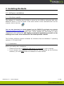
3.1.2 Installation
Before proceeding with installation:
Please ensure that no ENENSYS USB device is connected to your computer
If you already have ENENSYS’ devices that are not supported by the DiviSuite
software, you must first install the software for those devices.
DiviSuite 1.2 - User's Manual
9 / 66
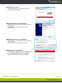
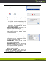
Launch the installer executable. This will display the following window.
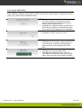
DiviSuite installation process uses common Windows installation process. The following
instruction details only specific screens. For other screens, please, follow the on screen
instruction.
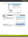
Select Components
Select “Full installation”. Keep WinPcap library
component. It is needed for IP input
management. This will install WinPcap 4.1.2
version.
WinPcap 4.1.2 Setup:
If WinPcap 4.1.2 is already installed on your
computer, you can cancel the installation. Else
proceed with WinPcap installation
DiviSuite 1.2 - User's Manual
10 / 66
WinPcap 4.1.2 Setup:
WinPcap Installation: keep default values
proposed by the installer.
ENENSYS 64 bits Driver Installation:
This applies only to 64bits operating systems,
not to 32bits.
Proceed with on screen instructions for
installation.
ENENSYS 64 bits Driver Installation:
This applies only to 64bits operating systems,
not to 32bits.
Accept installation by clicking “Install”.
ENENSYS Driver Installation:
If operating system ask for a confirmation
on installing ENENSYS driver software,
select “Install this software anyway”
DiviSuite 1.2 - User's Manual
11 / 66
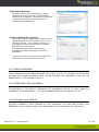
VideoLAN installation:
DiviSuite relies on VLC software for content
decoding. It is necessary to install the latest
release of this software. Follow the link provided
in the Setup windows to proceed with VLC
download and installation.
Plugin activation file selection:
If you have ordered plugins before delivery, the
plugin activation file is provided to you in the
USB key content, in the \options directory. It
may also have been sent by email if ordered
after delivery of the device.
This setup window allows importing the
activation file before starting the DiviSuite
application.
If you do not want to import an activation file,
press “Next” to proceed with next step.
3.2 Plugin activation
Plugin activation can be done at install time (refer to §3.1.2). However, you may also
proceed with plugin activation after having installed the application. This will be
detailed later in this manual in §5.9.1.
3.3 Calibration File activation
If applicable to the device, calibration file installation should be done after the
installation of the application. This will be detailed later in this manual in 5.9.4.
3.4 Connect your device
DiviSuite software is now installed on your computer; you can now connect your
ENENSYS’ device. Please, refer to the User’s Manual of your device for instructions.
DiviSuite 1.2 - User's Manual
12 / 66
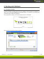
4 Starting with DiviSuite
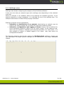
4.1 DiviSuite startup
To launch DiviSuite, double click on the icon created on your desktop at installation or
click on the “Start Menu\ENENSYS\DiviSuite\DiviSuite 1.2” shortcut in the start menu
of Windows also created at installation.
During application startup, the following splash screen is displayed.
Once started, the DiviSuite window appears:
DiviSuite 1.2 - User's Manual
13 / 66
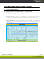
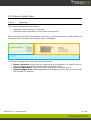
5 DiviSuite Basic Graphical User Interface
5.1 DiviSuite main window
The graphical interface of DiviSuite is organized in three main panels:
Menu panel: this panel contains menu items to select the content displayed in
the Context Panel. This panel is always visible.
Context panel: this panel can change depending on the Menu Panel. It allows
accessing to configuration and analysis features of the DiviSuite application.
Status Bar panel: this panel contains control and status of the analysis
features. It also contains controls for visible views of the Context panel. It is
always visible.
Menu Panel
Context Panel
Status Bar Panel
DiviSuite 1.2 - User's Manual
14 / 66
5.2 Menu Panel
The Menu panel contains four menu buttons which allows selecting the current view in
the Context panel:
“Device config.”: allows selection and configuration of the ENENSYS’ device and
its operation mode
“Settings”: allows configuration of DiviSuite Basic and plugins features.
“Monitoring”: displays the monitoring views of the current analysis.
“About”: general information about DiviSuite and plugin (including plugin activation).
The selected view in the Context panel appears highlighted in green, “Device Config.”
View in the example.
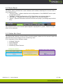
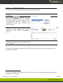
5.3 Status Bar Panel
The Status Bar features control of the current analysis, status on the current input and
selected device and control of the monitoring view.
It is composed of four different areas:
Analysis Controls
Input Statistics
Device Status
Monitoring View Controls
Analysis Control
Device Status
Monitoring View Control
Input Statistics
DiviSuite 1.2 - User's Manual
15 / 66
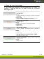
5.4 Status Bar Panel: Device Status
The Device Status gives information on current connected device and its state. It is
composed of a status LED, device name and status on current input. The different
states are given below.
State:
No device connected
Status LED is RED
Meaning:
No device is connected to the computer or no device is connected to
the DiviSuite
Corrective action:
Connect your device to a USB port of the computer
Go to Device Configuration and connect DiviSuite to the device
State:
Device connected (name reported)
Status LED is Orange
Meaning:
A device is connected but no analysis has been started
Corrective action:
Start the analysis
State:
Status LED is Orange blinking
A device is connected (name reported), analysis is started but no
stream is received
Meaning:
Although the analysis is started, no valid incoming stream is
detected.
Corrective action:
Check connection of the device to the input source equipment
Check input configuration parameters (RF channel, IP address…)
Check input source signal validity
State:
Status LED is Green blinking
A device is connected (name reported), analysis is started and
stream is received
Meaning:
Analysis is running
DiviSuite 1.2 - User's Manual
16 / 66
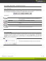
5.5 Status Bar Panel: Analysis Controls
5.5.1 Overview
The analysis and playback controls allows controlling current analysis. A device must
be connected to the DiviSuite software to make these controls active.
It features:
Input start
It is used to start analysis or playback on the current input; refer
to device configuration description for detailed information on
input configuration.
Input stop
It is used to stop current analysis or playback.
Input stream recording
It is used to record the current input stream in a file for offline
analysis.
Video display
It is used to decode and display video content using VLC player.
IP Forward
It is used to forward the input stream to an IP address (for
example towards a professional receiver)
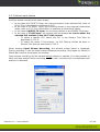
5.5.2 Input start
In order to be able to start reception of input stream, an input must be selected and
configured (refer to §5.10.4 for information on input configuration). To stop an
analysis, click on the Stop button. If input channel is not selected or misconfigured, the
following error is displayed:
RF input is selected but no RF channel is selected
DiviSuite 1.2 - User's Manual
17 / 66
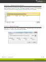
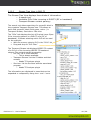
5.5.3 Record input stream
DiviSuite allows recording the input stream:
In the case of RF DVB-T2 input, the incoming stream is the selected PLP (refer to
§5.12.2 for information on selecting a PLP).
In the case of RF DVB-T input, the incoming stream is the selected hierarchical
mode (refer to 5.12.3 for information on selecting a hierarchical mode)
In the case of MPEG2-TS input, the incoming content is the MPEG2-TS stream.
In the case of T2-MI input, the content can be selected to record either the
selected PLP content or the full T2-MI content.
o To select a specific PLP, select the PLP in the Stream Tree View as
described in 5.12.2.
o To select the whole T2-MI stream, no PLP filtering should be done in
Stream Tree View as described in 5.12.2.
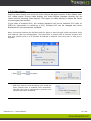
When starting Input Stream Recording, the window shown below is displayed.
During recording, it can be closed without stopping recording. Click again on Record in
Status Bar Panel to show again the window.
Input stream recording can be started before analysis is started. It is also possible to
start and stop analysis while recording. In this case, recording will be suspended until
analysis is restarted.
DiviSuite 1.2 - User's Manual
18 / 66
Status
o Give information on current recording (time
elapsed, file size)
Control
o Start
or stop
recording
Settings
o Record current filtered stream / Record all
plps
Record current filtered stream: in the case of
DVB-T2 T2-MI, record the content of active PLP
or complete T2-MI stream
Record all plps: in the case of DVB-T2 T2-MI,
record content from all PLP in separate files.
No meaning in other cases (RF DVB-T2 record
current PLP; other standard than DVB-T2
record MPEG2-TS standard)
o Destination Base Filename: base name of the
recorded file. Finale file name will be:
{Destination Base Filename}[_{index}].ts
Where {index} is a number indicating the file
index.
Already existing files are not replaced. Instead,
an index is incremented.
Scheduler
o Record countdown: check if a time countdown
is needed before starting recording. Use input on
its right to setup time countdown. This apply to
complete recording process, this means that if
multiple record are used, countdown will be done
once, before the first record starts.
o Record duration: check if you want to limit
recording to a specific duration. Use input on its
right to setup recording duration.
o Maximum file size: check if you want to limit
the file size to a specific size. Use input on its
right to setup maximum file size in Mbytes
o Number of records: check if you want to record
multiple files. A new record will be created each
time Record duration is elapsed and/or each time
Maximum file size is reached.
Infinite looped recording: repeat infinitely the
recording, with all settings except countdown done
once, until recording is manually stopped.
DiviSuite 1.2 - User's Manual
19 / 66
5.5.4 Video display
Starting video display will show the Video Output Manager window. Video display uses
VLC media player. During video display, the Video Output Manager window can be
closed without stopping video display. Click again on Video display in Status Bar Panel
to show again the window.
In the case of multiple PLPs, the content displayed will be the selected PLP (refer to
§TBD for information on selecting a PLP). Selected PLP can be changed and video
displayed will be automatically updated.
Note: Connection between the DiviSuite and VLC player is done through a UDP connection (local
host address, UDP port configurable). This connection is shared with IP Forward function and
thus may interfere with it if IP Forward IP address is different from local host or UDP port is
different.
Control
o Start
or Stop
VLC player
Control
o UPD port used for local streaming: VLC reads the
video content from a localhost UDP connection.
The UDP port can be configured to prevent from
collision with other softwares.
DiviSuite 1.2 - User's Manual
20 / 66
Starting Video Display will launch VLC media player. Please refer to VLC User’s Manual
for more information.
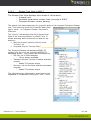
5.5.5 IP Forward
IP Forward can be used to send the input stream content towards remote equipment
through your IP network. It supports unicast or multicast transmission. Content is
broadcasted in MPEG2-TS over UDP format. The Ethernet controller used is one of the
computer controller.
Starting IP Forward will show the IP Forwarding Manager window. During IP forward,
the IP Forwarding Manager window can be closed without stopping IP forward. Click
again on IP forward in Status Bar Panel to show again the window.
In the case of multiple PLPs, the content forwarded to IP will be the selected PLP (refer
to 5.12.2 for information on selecting a PLP). Selected PLP can be changed and
forwarded content will be automatically updated.
o
In the case of a T2-MI input stream, either a specific PLP, either the
complete T2-MI stream can be forwarded to IP. To select the whole T2-MI
stream, no PLP filtering should be done in Stream Tree View as described
in 5.12.2.
Note: IP Forward function is shared with Video Display function and thus may interfere with it if
IP address is different from local host or UDP port is different.
DiviSuite 1.2 - User's Manual
21 / 66
Status
o Indicates if IP Forwarding is currently
stopped or started.
Control
o Start
or Stop
IP Forwarding
Settings
o Network adapter: select the Ethernet
controller of the computer through
which the IP Forward will send datas
o IP address and port: identify the
destination equipement. IP address
could be unicast or multicast.
DiviSuite 1.2 - User's Manual
22 / 66
5.6 Input Statistics
Input statistics displays information about the current input stream. It depends on the
input type. Each case is detailed below.
RF Input:
The LED indicates the state of the RF
front end. Green means locked (signal
found), RED means unlock
Indicates the channel name as defined in
channel list of Device Configuration panel, as well as RF frequency and standard.
ASI Input:
Indicates the ASI input is in use.
IP Input:
Indicates the IP stream name as defined
in channel list of Device Configuration
panel, as well as IP address and UDP
port.
File Input:
Indicates the current played file
Indicates the elapsed time in the file
(HH:MM:SS) as well as loop count (how
many time the file list has been played).
DiviSuite 1.2 - User's Manual
23 / 66
5.7 Monitoring View Control
Monitoring View Control allows showing or hiding monitoring views of the Context
Panel.
Note: Hiding or showing analysis view does not mean starting or stopping an analysis. This one
continues to be ran in background even if its monitoring view is hidden.
Controls of this area have different states depending on conditions listed below. The
example below show the possible states for the RF-T2 control. It is applicable to other
controls.
The analysis is enabled and its view is displayed in the Monitoring View
The analysis is enable but its view is not displayed in the Monitoring View
The analysis is disabled
There are three reasons for a disabled analysis:
The analysis is not supported by the connected device.
o Contact ENENSYS TestSystems team for information on devices supporting
this analysis.
The analysis is part of a plugin and the plugin has not been activated.
o Validate that the plugin has been activated
The analysis has been disabled in the Setting panel.
o Go to settings panel and enable the analysis.
The available controls are
RF Scope in DVB-T2 Monitoring View, needs RFScope plugin
RF Scope in DVB-T Monitoring View, needs RFScope plugin
ETR 290 Monitoring View, needs TS Analyzer plugin
PCR Monitoring View, needs TS Analyzer plugin
Bitrate Monitoring View, included in DiviSuite Basic
Alarms Monitoring View, included in DiviSuite Basic
T2-MI Monitoring View, needs T2MI Analyzer
DiviSuite 1.2 - User's Manual
24 / 66
5.8 Context Panel
The content of this panel depends on the selected menu in Menu Panel: Device
Configuration, Settings, Monitoring and About views. This chapter describes the content
of those views of the DiviSuite Basic software. Dedicated chapters are also available in
this manual for specifics views of each plugin.
5.9 Context View: About
This view gives information about the software version of the installed DiviSuite
software. It also gives access to the plugins information and activation.
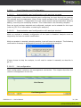
5.9.1 Software Information
It contains information on the application and ENENSYS contact.
Software Version: indicates the version of the installed application.
Web Site: click on the link to open a browser window on the ENENSYS
TestSystem website
Download Center: click on the link to open a browser window on the ENENSYS
privileged area. You will find there information on the current release of the
products, datasheet, manuals and software revision. You need to register on this
website to gain full access. It is highly recommended by ENENSYS support team
to ensure you will have information on latest release.
Check For Updates: when you click on this button, the application will check if
a newer revision exists for the DiviSuite application. If this is the case, it will
propose you to install it.
DiviSuite 1.2 - User's Manual
25 / 66
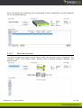
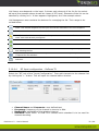
5.9.2 Device Management
It contains information on the option files and calibration files already registered with
your application.
For example, the following information means:
ReFeree T2 S/N 550110AI is registered
o With RFScope, TS Analyzer and T2MI analyzer plugin enable.
o A calibration file, generated on September, the 21st of 2009 has also been
provided
ReFeree T2 S/N 550110AO is registered
o With RFScope, TS Analyzer and T2MI analyzer plugin enable.
o No calibration file has been registered for this device.
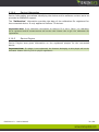
5.9.3 Plugin activation
Each plugin is activated for a specific device and is available only for this device 1.
To activate a plugin, click on the Import button and select the plugin activation file
provided by ENENSYS TestSystems. Application will then be restarted in order to
activate the new plugins.
5.9.4 Calibration activation
Each calibration file is activated for a specific device and is available only for this
device1.
To import a calibration file, click on the Import button and select the calibration file
provided by ENENSYS TestSystems. Application will then be restarted in order to
activate the calibration.
1
DiviSuite can be installed on multiple computers. It is then necessary to activate plugins and
calibration for a specific device on all these computers to be able to use the device on each
computer.
DiviSuite 1.2 - User's Manual
26 / 66
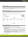
5.10 Device Config View
5.10.1
Overview
The device configuration view allows:
Selection and connection to a device
Selection and configuration of the inputs of the device
When launching the DiviSuite software without a connected device or after unplug of
the device from the USB, the following view is displayed.
The Device Configuration view has three main areas:
Device selection: allows listing, selecting and connecting to a specific device.
Only the supported devices will be listed in the device list.
Device Information: gives information about the connected device.
Input Configuration: allows selecting and configuring the inputs of device that
will be used for analysis.
DiviSuite 1.2 - User's Manual
27 / 66
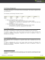
5.10.2
Connect a device
To connect to a device, follow the procedure describe below.
Connect the device to a USB port of the
computer
Click the
button of the
Device Selection area. This will update
the Device Selection area with the list
of supported devices1. Devices are
identified by their part number and
serial number.
Select the device to connect to and click
connect. It will update the Device
information and Input Configuration
areas.
To select another device while already
connected, select the new device and
click connect.
If a device is already connected to the DiviSuite, the connection is automatically done
as described in §4.1.
1
It may be needed to click again the “Refresh” button until the operating systems detects and
configures the USB device.
DiviSuite 1.2 - User's Manual
28 / 66
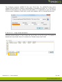
Once connected, the following view is displayed (Input Configuration content depends
on the connected device).
5.10.3
Select device mode
For devices supporting player and analyzer mode, the following view is displayed. The
“Analyzer Mode” and “Player Mode” buttons allow selecting between analyzer and
player mode.
DiviSuite 1.2 - User's Manual
29 / 66
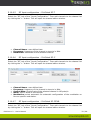
5.10.4
Device Information
Device Information area allows identifying the device and its software revision as to be
provided to ENENSYS support.
The “Calibration” information provides the date of the calibration file registered for
the connected device. It only applies to ReFeree T2 devices.
Important Note: If the calibration information for ReFeree T2 is set to “None”, no calibration
file is registered and RF measurements will not be valid. Please refer to §3.3 for calibration file
registration.
5.10.5
Device Plugins
Device Plugins area gives information on the registered plugins for the connected
device.
Important Note: If a plugin is not registered, the features belonging to this plugin will not be
activated. Please refer to §3.2 for plugin registration.
DiviSuite 1.2 - User's Manual
30 / 66
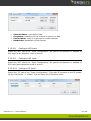
5.10.6
Input Selection and Configuration
5.10.6.1
Input selection and configuration with analysis stopped
Input Configuration view allows selecting and configuring the input that will be used for
the analysis and its parameters. Most of the inputs manage a list of configuration: RF
channels, IP streams… Configuration for such inputs shares a same framework allowing
adding, removing and modifying channel. This is described in the following chapters.
Once an input has been selected and configured, analysis can be started for this input
(refer to §5.5.2 for information on starting an analysis).
5.10.6.2
Input selection and configuration with analysis started
While an analysis is started, configuration of the input is disabled. Analysis must be
stopped by the user to enable modification.
While an analysis is started, selecting another input will stop the analysis. The following
confirmation message is displayed to prevent from stopping the analysis.
If user choose to stop the analysis, he will need to restart it manually as describe in
§5.5.2.
5.10.6.3
List configuration
Input configuration includes a list management mechanism. This chapter describes the
common management of such list.
List Viewer
List Management
DiviSuite 1.2 - User's Manual
31 / 66
List Viewer area depends on the input. It shows each element of the list for the selected input (the example above shows list viewer of RF Input). Elements of the list can be
selected by clicking on it. It then appears highlighted, as in the example above.
List Management area contains the buttons for managing the list. Their usage is described below.
Add an element to the list. It opens a window for selecting the parameters of the element. This window depends on the input and will be described in the next chapters.
Remove the selected element from the list
Modify the selected element of the list. It opens the same window as for the add element with fields already configured.
Move the selected element up in the list
Move the selected element down in the list
Create a new list. Current list will be deleted. A confirmation message is displayed before deleting the list
Open a list. It loads a list from a file (this deletes the current one). An open file window
is opened for file selection
Save current list. It saves the current list to a file. An save file window is opened for file
selection.
5.10.6.4
RF Input configuration – ReFeree T2
Select the “RF” tab of the “Input Configuration”. Then add channels to the channel list
by clicking the “+” button. This will open the channel editor window.
Channel Name and Comments: user defined text
Frequency: frequency of the channel to tune to in MHz.
Bandwidth: bandwidth of the selected channel
Standard: select DVB-T or DVB-T2 to choose which standard is to be used for
channel decoding.
DiviSuite 1.2 - User's Manual
32 / 66
5.10.6.5
RF Input configuration – DiviCatch RF-T
Select the “RF” tab of the “Input Configuration”. Then add channels to the channel list
by clicking the “+” button. This will open the channel editor window.
Channel Name: user defined text
Frequency: frequency of the channel to tune to in MHz.
Bandwidth: bandwidth of the selected channel
5.10.6.6
RF Input configuration – DiviCatch RF-C
Select the “RF” tab of the “Input Configuration”. Then add channels to the channel list
by clicking the “+” button. This will open the channel editor window.
Channel Name: user defined text
Frequency: frequency of the channel to tune to in MHz.
Symbol Rate: Symbol rate of the selected channel in MSymbol/s
Mode: DVB-C Mode of the channel
Modulation: select automatic for automatic configuration of the modulation or
force a specific modulation.
5.10.6.7
RF Input configuration – DiviCatch RF-DTMB
Select the “RF” tab of the “Input Configuration”. Then add channels to the channel list
by clicking the “+” button. This will open the channel editor window.
DiviSuite 1.2 - User's Manual
33 / 66
Channel Name: user defined text
Frequency: frequency of the channel to tune to in MHz.
Carrier Mode: multi or single carrier mode selection
Bandwidth: Bandwidth of the channel
5.10.6.8
Configure ASI input
Select the “ASI” tab of the “Input Configuration”. No specific configuration is needed on
ASI input (auto detection mode is active).
5.10.6.9
Configure SPI input
Select the “SPI” tab of the “Input Configuration”. No specific configuration is needed on
SPI input (auto detection mode is active).
5.10.6.10 Configure IP Input
Select the “IP” tab of the “Input Configuration”. Then add IP streams to the IP stream
list by clicking the “+” button. This will open the IP streams editor.
DiviSuite 1.2 - User's Manual
34 / 66
5.10.6.10.1
Ethernet Controller selection
IP input use one of the Ethernet controllers of the computer. It is needed to selects
which controller needs to be used. The Network Adaptor Interface list all detected
controllers. Use this field to select which one should be used for IP reception.
5.10.6.11 Configure File Input
Select the “File” tab of the “Input Configuration”. Then add files to the File list by
clicking the “+” button. This will open the File editor.
DiviSuite 1.2 - User's Manual
35 / 66
The DiviSuite supports MPEG2-TS files and T2-MI files. For MPEG2-TS files which
contain PCR information, bitrate is automatically computed and filled. For T2-MI files or
MPEG2-TS files that do not contain PCR information, it is requested to give the bitrate
of the stream. Mandatory fields with invalid value appear with an orange background.
5.10.6.11.1
Loop mode activation
DiviSuite allows playing in loop mode the list of files of the File input. To enable or
disable the loop mode, check or uncheck the “Enable Loop mode” field.
DiviSuite 1.2 - User's Manual
36 / 66
5.10.7
Output Selection and Configuration
Output Configuration view allows selecting and configuring the output that will be used
for the playback and its parameters. This only applies to Player Mode. Refer to
§5.10.3 for selecting the Player Mode.
In Player Mode, the device uses a file as stream input. You need to configure the file
input before starting the playback. Please, refer to §5.10.8 for configuring file input.
Important Note: Output Configuration is available only when no playback is running.
Once an output has been selected and configured, playback can be started (refer to
§5.5.2 for information on starting a playback).
5.10.7.1
Configure ASI output
Select the “ASI” tab of the “Output Configuration”. Then configure settings for the ASI
output.
ASI Mode: select between Continuous or Burst mode.
o In Continuous mode, ASI sync words are added between and inside
MPEG2-TS packets.
o In Burst mode, ASI sync words are only added between MPEG2-TS
packets.
Framing: Select MPEG2-TS packet size on the ASI output.
o Auto: use the framing used in the input file
o 188: force a 188 bytes packet length, whatever the input file framing is.
If input file framing is 188 bytes, Read Solomon bytes are removed from
the MPEG2-TS packets.
o 204: force a 204 bytes packet length, whatever the input file framing is.
If input file framing is 188 bytes, null Reed Solomon values are added to
the MPEG2-TS packets.
o Raw Mode: In Raw Mode, the device does not take into account the
synchronization byte of the MPEG2-TS packets of the input file. All bytes
from the file to the ASI output.
Remove Null Packets: When selected, the device sends the source MPEG2-TS
stream without the MPEG2-TS null packets (PID 0x1FFF) contained in it. This will
result in a variable bitrate transport stream on the ASI output.
DiviSuite 1.2 - User's Manual
37 / 66
5.10.7.2
Configure SPI output
Select the “SPI” tab of the “Output Configuration”. Then configure settings for the SPI
output.
Framing: Select MPEG2-TS packet size on the SPI output.
o Auto: use the framing used in the input file
o 188: force a 188 bytes packet length, whatever the input file framing is.
If input file framing is 188 bytes, Read Solomon bytes are removed from
the MPEG2-TS packets.
o 204: force a 204 bytes packet length, whatever the input file framing is.
If input file framing is 188 bytes, null Reed Solomon values are added to
the MPEG2-TS packets.
o Raw Mode: In Raw Mode, the device does not take into account the
synchronization byte of the MPEG2-TS packets of the input file. All bytes
from the file to the SPI output.
Remove Null Packets: When selected, the device sends the source MPEG2-TS
stream without the MPEG2-TS null packets (PID 0x1FFF) contained in it. This will
result in a variable bitrate transport stream on the SPI output.
DiviSuite 1.2 - User's Manual
38 / 66
5.11 Settings view
Settings view allows configuring the analysis of the DiviSuite software.
It has one menu bar per analysis type and a settings area depending on the selected
menu bar.
When an analysis is not enabled, fields of the settings are disabled (greyed). If the
analysis depends on plugin activation, it is indicated on top of the settings area. The
example below does not have RFScope plugin activated.
Settings comprise various possibilities:
Activation or deactivation of an analysis: deactivating an analysis may be
useful if the used computer do not have the required processing power.
Activation, configuration and logging of alarm: alarms can be defined for
some parameters analysis (refers to §0 for alarm usage). In the Settings view,
alarm can be enabled or disabled per analyzed parameter. For each alarm, it is
also possible to enable or disable logging of an alarm. Last, each alarm as
configurable threshold.
The following chapters describe the settings for DiviSuite Basic software: bitrate and
log. Description for plugin specific settings will be described in the plugin dedicated
chapter.
DiviSuite 1.2 - User's Manual
39 / 66
5.11.1
Validation of a setting
In all settings panel, when changing a value, a confirmation is needed. In this case, the
icons are displayed. A click on
icon validates the modification while a click on
discards the modification.
These icons allows validation or discards of all settings displayed in the current view.
5.11.2
Activation and log of an alarm
To enable an alarm, check the “On” parameter on the line of the alarm and validate the
modification.
To enable logging an alarm, check the “Log” parameter on the line of the alarm and
validate the modification.
Two modes are available for alarm firing:
Continuous mode: alarm is fired and log until the parameter is out of defined
values
Transition mode: alarm is toggled and log once when the parameter change
from valid range to invalid range and vice versa.
In order to enable or disable quickly all settings, some panels have a global selection
check box.
DiviSuite 1.2 - User's Manual
40 / 66
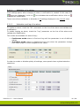
5.11.3
Bitrate setting
Bitrate settings allow defining minimum and maximum threshold which fire an alarm. A
threshold can be defined for:
The overall bitrate of the MPEG2-TS stream
The Net bitrate of the MPEG2-TS stream
The bitrate of a specific PID
To add bitrate monitoring for a specific PID, enter the value in the text field of the “PID
bitrate alarms” group box and click on “+” button. To remove it, enter the value in
the text field and click on “-”.
When an analysis is running, it is also possible to select between the PID of the stream.
Click on the
in the list.
button to refresh the PID list of the drop down list then select the PID
DiviSuite 1.2 - User's Manual
41 / 66
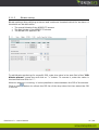
5.11.4
Log setting
Log setting allows configuring the log file management of the DiviSuite. It allows
defining the log file that will be used by DivSuite.
A stop condition on the log file needs to be defined. This allows recording logs only
during specific analysis duration or preventing from a huge file size of the log file. This
is configurable through the Max file size or Max saving time fields while the Max Entries
field allows creating chunk of log files up to a specific number of chunks.
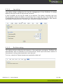
5.11.5
DiviSuite setting
This setting allows configuring the behavior of the application at startup. DiviSuite can
automatically start an analysis on the same devive, same input and same channel of
the analysis running when application was last quit.
To do so, check the “Restart analysis at application start-up”.
DiviSuite 1.2 - User's Manual
42 / 66
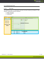
5.12 Monitoring View
5.12.1
Overview
The Monitoring View is a configurable area which receives monitoring windows for each
analysis. Three main areas are available:
Stream Tree View
Analysis Windows
Log Windows
Analysis Windows
Stream Tree
View
Log window
DiviSuite 1.2 - User's Manual
43 / 66
5.12.2
Stream Tree View in DVB-T2
The Stream Tree View displays three kinds of information:
o A search tool
o Available PLPs if the incoming is DVB-T2 (RF or baseband)
o Transport Stream content parsing:
The search tool allows searching for a specific label in
the complete Transport Stream tree. This allows to
quick find a specific label (field name, value…) in
Transport Stream, Services or PIDs tree.
The “PLPs” tab displays the list of Physical Layer Pipes
if the incoming stream is a DVB-T2 one (RF or
baseband). It allows selecting which PLP will be used
for the analysis:
With the mouse, select a PLP in the “PLPs” list
Drag and drop to “PLP Filter”
The Transport Stream tab displays MPEG2-TS content
of a PLP or of the incoming MPEG2-TS baseband
stream. The content can be browsed by:
o PID list: list of PIDs detected
o This is always available
o Transport Stream: list the SI tables and their
content
o Needs TS Analyzer plugin
o Services: list the Services and the associated
program
o Needs TS Analyzer plugin
The information are displayed in trees that can be
expanded or collapsed by using the + and – icons.
DiviSuite 1.2 - User's Manual
44 / 66
5.12.3
Stream Tree View in DVB-T
The Stream Tree View displays three kinds of information:
o A search tool
o Available hierarchical modes if the incoming is DVB-T
o Transport Stream content parsing:
The search tool allows searching for a specific label in the complete Transport Stream
tree. This allows to quick find a specific label (field
name, value…) in Transport Stream, Services or
PIDs tree.
The “Priority” tab displays the list of Hierarchical
Mode if the incoming stream is a DVB-T one It
allows selecting which mode will be used for the
analysis:
With the mouse, select a priority in the
“Priority” list
Drag and drop to “Priority Filter”
The Transport Stream tab displays MPEG2-TS
content of a PLP or of the incoming MPEG2-TS
baseband stream. The content can be browsed by:
o PID list: list of PIDs detected
o This is always available
o Transport Stream: list the SI tables and their
content
o Needs TS Analyzer plugin
o Services: list the Services and the associated
program
o Needs TS Analyzer plugin
The information are displayed in trees that can be
expanded or collapsed by using the + and – icons.
DiviSuite 1.2 - User's Manual
45 / 66
5.12.4
Stream Tree View tools
5.12.4.1
Search tool
The « Search » field on the top of the Stream Tree View allows to search for a label or
a value in all the Stream Tree View. Enter the searched value and hit “Enter” until you
find the field of interest.
5.12.4.2
Report tool
Stream Tree View allows Copy/Paste functionality. Select the part of the tree you want
to copy by clicking on it (it could be on the root or on a leaf of the tree), type CTRL+C.
The content of the selected field and all associated fields is copied in the clipboard of
the Windows operating system and can then be copied in another application.
5.12.5
Logs View
This window displays the logs on the fly. The log for specific parameters can be
configured and enabled via the “Settings” panel.
5.12.6
Monitoring Windows
The Monitoring View contains the panels for specific analysis. Those panels can be
displayed or hidden by clicking on the button of the Monitoring View Control of the
Status Bar Panel as defined in §0.
DiviSuite 1.2 - User's Manual
46 / 66
5.12.6.1
Customization of the Monitoring Windows position
The Monitoring Windows position is configurable. It can be displayed by tabs (orange
area below) or tiled (green area below). To configure your global view:
o Choose a view by selecting its tab
o Drag inside the monitoring view: Available area for dropping appears in
blue.
o Drop when you find the position you want.
DiviSuite 1.2 - User's Manual
47 / 66
5.12.6.2
Typical control of monitoring windows
Monitoring Windows have some common controls to ease the use of DiviSuite.
The
icon is a shortcut to go to the Device Configuration panel.
The
icon is a shortcut to go to the settings panel of the analysis of the monitoring
window.
Some windows also have PID or Services filtering. It allows running the analysis of the
windows only on the selected PID or Services.
To run the analysis on a specific PID or Service, select this PID or Service in the Stream
Tree View and drop it in the indicated area (“Drag & drop pid or service here”).
The “Reset Filter” button removes the filtering analysis of the current PID or Services
to apply it to the whole stream.
The “Reset” button reset all values of the analysis windows. It is for example used to
reset error counters.
DiviSuite 1.2 - User's Manual
48 / 66
5.12.7
Alarm Monitoring Window
Alarms are fired when a parameter go outside the range defined in the settings panel.
Alarm analysis can be done on the whole stream content or specific part by PID or
service filtering.
An alarm has three possible states:
Greyed: the alarm has not been activated in the Settings panel
Green: alarm is activated and no out of range has been detected on the
parameter
Red: alarm is activated and out of range has been detected on the parameter. A
counter is displayed at the right of the alarm indicating how many times it has
been fired, according to continuous or transition mode defined in the Settings
Panel.
Each analysis has its own alarms defined. All activated alarm will be displayed in this
panel.
DiviSuite 1.2 - User's Manual
49 / 66
5.12.8
Log Monitoring Window
The Log monitoring view displays all events of interest of the analysis: analysis start
and stop, alarms for which logging has been enabled…
Independently of Log file activation in the Settings Panel, this window is always
displayed. It can be docked using the icon in its top right.
5.12.9
Bitrate Monitoring View
The Bitrate monitoring view display bitrate for overall and net bitrate as well as bitrate
for specific PIDs. To add a PID to this display, select the PID in the Stream Tree View
and drag’n’drop it in this window.
The
icon is used to show ( ) or hide ( ) the graph of a specific bitrate. The
icon allows moving a PID from the monitoring graph.
When moving the mouse pointer on top of graphs, the displayed is freezed and value is
displayed in the bottom of the windows with the computer time of the measure.
DiviSuite 1.2 - User's Manual
50 / 66
5.13 Profile management
In order to keep track of configuration, DiviSuite uses profiles to store the settings.
Those profiles are linked to the computer on which the DiviSuite is runned and to the
device for which configuration has been done.
DiviSuite 1.2 - User's Manual
51 / 66
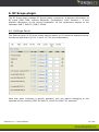
6 RF Scope plugin
The RF Scope plugin manage RF Signal Quality monitoring. It displays information on
RF signal (SNR, MER, Impulse Response, Constellation, LDPC iteration…). It also
displays information on the current modulation. All the parameters depend on the
standard: DVB-T, DVB-T2, DVB-C, DTMB…
6.1 Settings Panel
The Settings panel of RF Scope allows setting alarms on RF values as displayed below.
Proceed as described in §5.11.1 and 5.11.2 for the configuration.
Note that when analyzing a specific standard, only the alarms belonging to this
standard will be checked (LDPC for DVB-T2, Viterbi for DVB-T for example).
DiviSuite 1.2 - User's Manual
52 / 66
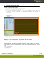
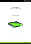
6.2 RFScope Monitoring view
RFScope Monitoring View includes:
Instantaneous value display using bar graphs,
Historical value display using graphs
Modulation parameters information. In the case of DVB-T2, a second panel, T2
L1 is also available to display all modulation parameters of the DVB-T2
modulation.
Instantaneous
Values
Historical view
DVB-T2 Active PLP
Information
Depending on the connected device, the Historical view also includes:
Echoes (channel impulse response)
Constellation
On some devices, Constellation display and Transport Stream reception are exclusive.
In this case, a “Further RF Measurements” check box is available to select the current
mode.
DiviSuite 1.2 - User's Manual
53 / 66
The T2 L1 view displays information conveyed by the L1 signaling. To get L1 post
signaling information for all PLPs, click on the “Refresh PLPs infos” to get the values.
This stops the current reception of the PLP during the measurement.
DiviSuite 1.2 - User's Manual
54 / 66
6.2.1 Monitoring views
This view provides a monitoring of instantaneous values over the last 60 seconds:
Signal level
SNR
MER
LDPC iteration number, Pre LDPC, Post LDPC and Post BCH BER for DVB-T2
Pre Viterbi BER and Post Viterbi BER for DVB-T
For each measurement, use can check the minimum value, the maximum value and
the average over the last 60 seconds. This can be done by dragging the mouse
pointer over the colored rectangle in the top left of the view.
DiviSuite 1.2 - User's Manual
55 / 66
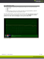
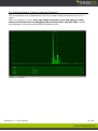
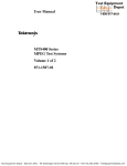
6.2.2 Echoes Pattern (Channel Impulse Response)
This view displays the instantaneous Channel Impulse Response detected by the receiver.
Main echo appears in blue. User can check the power level and delay of other
echoes from main echo by dragging the mouse pointer over the echo. Values
are displayed in the text area below the graphical view.
DiviSuite 1.2 - User's Manual
56 / 66
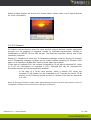
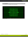
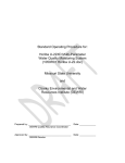
6.2.3 Constellation
This view displays the constellation of the received signal.
DiviSuite 1.2 - User's Manual
57 / 66
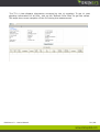
6.3 Report File
When RFScope plugin is enabled, user can access the Report File feature though the
settigns panel. It allows creating files with periodic measurement. Report files are CSV
file with values separated by a semi colon and field name as the first line.
6.3.1 File Segment Configuration
Report File feature allows creating multiple files for the measurement sessions. These
files are named segment file. Each segment size can be controlled by the user by
setting:
The maximum segment size in Mega Bytes
Or the maximum segment time duration
Or the maximum number of measurements in the segment
Each segment will be named with the following rule:
Use destination directory of the Basename field
Use the file basename with _{ID} suffix, where {ID} is the segment number
Use file extension of the Basename
The screenshot below will lead to creating c:\report-coverage_1.csv, c:\reportcoverage_2.csv, … files with a size of 1MB.
Please note that if segment files already exist with the same rule, they will not be over
written. Numbering will start at the next available index.
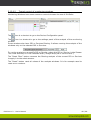
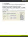
6.3.2 Report Configuration
The Record Period field allows setting the periodicity of the measurements, with a
minimum of 1 second.
DiviSuite 1.2 - User's Manual
58 / 66
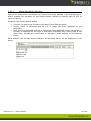
7 TS Analyzer plugin
The TS Analyzer plugin manage SI table decoding (displayed in Stream Tree View), ETR
290 analysis and PCR analysis.
7.1 Setting Panel
Two settings panels are linked to TS Analyze plugin: Tables and ETR 290.
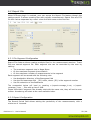
7.1.1 Table settings
The Tables analysis allows decoding of System Information tables of the incoming
stream. It can be enabled or disabled in the Setting panel.
The Transport Stream Standard allows choosing which standard decoding should be
applied to the stream. Already available table decoding standards are MPEG2-TS, DVB,
ATSC or ISDB. It is also possible to force table decoding on a specific PID. Add and
remove PID in the “Specific decoding rules” area.
DiviSuite 1.2 - User's Manual
59 / 66
7.1.2 ETR 290 Settings
The ETR 290 analysis allows PCR and ETR 209 analysis of the stream. It can be
enabled or disable.
ETR 209 Level 1, 2 and 3 are supported. Use the drop down list to view settings of a
specified level. Alarms can be enabled or disabled for each parameters.
PCR analysis is configured using the PCR filter profile as defined by the standard:
MGF1, MGF2 and MGF3 profiles. MGF1 gives the better results in term of accuracy of
measurements but needs a lot of time to be valid while MGF3 is fast to provide results
but with less accuracy.
DiviSuite 1.2 - User's Manual
60 / 66
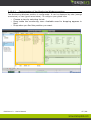
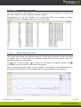
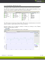
7.2 TS Analyzer Monitoring view
TS Analyzer plugin includes ETR 290 monitoring window and PCR monitoring window.
The ETR 290 monitoring window display alarms for each enabled parameter on the
whole stream content or specific part by PID or service filtering.
The PCR analysis monitoring window display PCR accuracy measurements on the whole
stream content or specific part by PID or service filtering.
Accuracy values can be viewed by density of history by clicking on the “Display
Density”/”Display History” button.
The
icons allow managing the zoom on the graph.
DiviSuite 1.2 - User's Manual
61 / 66
8 T2MI Analyzer plugin
The T2MI Analyzer plugin manage T2-MI baseband signal monitoring. The signal can
come from ASI, IP or file input. It displays information on T2-MI structure and DVB-T2
parameters.
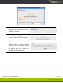
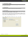
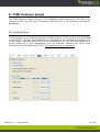
8.1 Setting Panel
T2-MI analysis can be disabled through the setting panel. T2-MI streams are embedded
in a MPEG2-TS stream using data piping. Depending on the equipment delivering the
T2-MI stream, the data piping PID can be extracted from PAT and PMT tables as a
private data PID or PID identification can be manually entered. For using Auto
extraction from PSI tables (PAT, PMT), TS Analyzer plugin is mandatory.
DiviSuite 1.2 - User's Manual
62 / 66
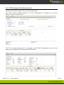
8.2 T2MI Analyzer Monitoring view
Monitoring windows include T2 L1 and T2-MI windows.
The T2-MI window display analysis of T2-MI encapsulation. It displays in real time
bitrate for each conveyed PLP.
The T2-L1 window displays the L1 signaling of the DVB-T2 parameters which will be
used by the modulator for generating the RF signal.
DiviSuite 1.2 - User's Manual
63 / 66
9 Equipment return for repair
In case of any trouble with one of ENENSYS Technologies' products, please report it to
our Technical Support team via email ([email protected]). Your request should
specify Part Number and Serial Number as displayed on the bottom label of the
equipment, with a description of the defect, reference of Purchase Order if possible,
and your full details.
Upon receiving your request, a support engineer will get in touch with you in order to
surely identify the source of your problem. If equipment has to be returned for repair, a
RMA21 number will be provided to you. You will need to indicate it on the shipping box
of the faulty equipment, and/or add it in your communication with our support team.
Your equipment will be shipped back to you along with a repair report.
1
Returned Material Authorization
DiviSuite 1.2 - User's Manual
64 / 66
10 Upgrades and Privileged Area
A privileged area (http://privileged.enensys.com) is available on ENENSYS' web-site.
Any registered user has access to the privileged area where general documentation,
user's manuals, software and product upgrades can be downloaded. In order to get
access to the privileged area, you will have to register on your first access. You will
then receive a password that will give you access to the privileged area.
Product upgrades will be announced on the registered users mailing list.
DiviSuite 1.2 - User's Manual
65 / 66
11 Contact Information
ENENSYS TestSystems
A division of ENENSYS Technologies
6 rue de la Carrière
CS 37734
35577 Cesson Sévigné CEDEX
FRANCE
Office
(+33) 810 ENENSY
(+33) 810 36 36 79
Fax
(+33) 2 99 36 03 84
Contact email:
[email protected]
Technical support email: [email protected]
DiviSuite 1.2 - User's Manual
66 / 66