1
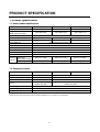
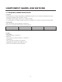
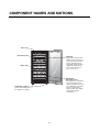
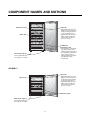
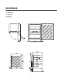
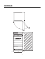
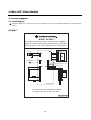
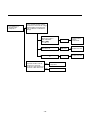
WINE CELLER
SERVICE MANUAL
CAUTION
BEFORE SERVICING THE UNIT, READ THE "SAFETY
PRECAUTIONS" IN THIS MANUAL.
GC-W061***
GC-W101***
GC-W141***
TABLE OF CONTENTS
1. Product Specification.................................................................................................................................... 4
2. Component Names and Motions.................................................................................................................. 5
3. Exterior .......................................................................................................................................................... 8
4. Circuit Diagram ......................................................................................................................................... 13
5. TROBLESHOOTING......................................................................................................................................15
6. Micom Function and Circuit Diagram ..................................................................................................... 21
7. Special Features
....................................................................................................................................... 37
8. Standard Self-Diagnostic Function............................................................................................................ 38
9. Maintenance ................................................................................................................................................. 39
10. Handle Disassembling, Assembling Instruction .................................................................................... 42
11. Service Parts Chart ................................................................................................................................... 43
SAFETY INSTRUCTIONS
Please read the following instructions before servicing your
7. When tilting the set, remove any materials on the set,
especially the thin plates(ex. Glass shelf or books.)
refrigerator.
8. Leave the disassembly of the refrigerating cycle to a
specialized service center. The gas inside the circuit
may pollute the environment.
1. Check the set for electric losses.
2. Unplug prior to servicing to prevent electric shock.
3. Whenever testing with power on, wear rubber gloves to
prevent electric shock.
9. When you discharge the refrigerant, wear the protective
safety glasses or goggle for eye safety.
4. If you use any kind of appliance, check regular current,
voltage and capacity.
10. When you repair the cycle system in refrigerator, the
work area is well ventilated.
Especially if the refrigerant is R600a, there are no fire
or heat sources. (No smoking)
5. Don't touch deep-frozen products in the freezer with wet
hands. This may cause frostbite.
6. Prevent water from following onto electric elements in
the mechanical parts.
-2-
SERVICING PRECAUTIONS
Features of refrigerant (R600a)
After the refrigerant (R600a) is completely discharged, repair any
defective parts and replace the dryer. At any case you must use the
LOKRING for connecting or replacing any part in the cycle (No Fire,
No Welding). Connect the Schrader valve to pump with the coupler.
And then turn the pump on for vacuum state (Figure 3). Let the pump
run until the low-pressure gauge indicates the vacuum (gauge
pressure 0, absolute pressure -1atm or -760mmHg). Recommended
vacuum time is 30 min. Charge the N2 gas in order to check for
leakage from welding points and the LOKRING. If leakages are
found, repair the defects and repeat the vacuum process.
• Achromatic and odor less gas.
• Flammable gas and the ignition (explosion) at 494°C.
• Upper/lower explosion limit: 1.8%~8.4%/Vol.
Features of the R600a refrigerator
• Charging of 60% refrigerant compared with a R134a model
• The suction pressure is below 1bar (abs) during the operation.
• Because of its low suction pressure, the external air may flow in the
cycle system when the refrigerant leak, and it causes malfunction in
the compressor.
• The displacement of compressor using R600a must be at least 1.7
times larger than that of R134a.
• Drier type is XH-9.
• The EVAPORATOR or any other cycle part that has welding joint is
hidden in the foam. (If not hidden inside, the whole electric parts
must be tested with the LEAKAGE TEST according to the IEC
Standard.)
• The compressor has label of the refrigerant R600a.
• Only the Service man must have an access to the system.
TO THE
VACUUM
PUMP
PRESSURE
GAUGE
Figure 3
After the system is completely vacuumed, fill it with the refrigerant
R600a up to what has been specified at your refrigerator Name Plate.
The amount of refrigerant (R600a) must be precisely measured within
the error of ±1g by an electron scale (Figure 4).
If you use the manifold connected with both the refrigerant (R600a)
cylinder and the vacuum pump simultaneously, make sure the pump
valve is closed (Figure 5).
Installation place
• Must be well ventilated.
• Must be 20 m3 or larger.
• Must be no-smoking area.
• No ignitable factors must be present.
Utilities
• Refrigerant cylinder (MAX NET 300g)
• Manometer
• Vacuum pump (600L/min)
• Piercing Clamp
• Quick coupler
• Hoses (5m-1EA, 1m-3EA)
• LOKRING
• Portable Leakage detector (3g/year¯)
• Nitrogen cylinder (for leakage test)
• Concentration gauge
REFRIGERANT
(R600a)
CHARGING HOSE
COUPLE
THROTTLE
VALVE
WEIGH SCALE
Figure 4
Make sure before Servicing
• Refrigerant
Confirm the refrigerant by checking Name Plate on innerliner and
the label on the compressor.
• If the refrigerant is R600a, you must not weld or apply a heat source.
FILLING OR
CHARGE TUBE
TO THE
REFRIGERATION
SYSTEM
Air Recharging in Compressor
Before refilling the refrigerant, you must perform the test according to
Chapter 5 (TROUBLESHOOTING CHART). When the defects are
found, you must discharge the residual refrigerant (R600a) in the
outdoor. For discharging the refrigerant R600a, break the narrow
portion of tube extension by hand or with a pipe cutter as shown in
Figure 1. Leave it for 30min in outside to stabilize the pressure with
ambient. Then, check the pressure by piercing the dryer part with
piercing pliers. If the refrigerant is not completely discharged, let the
refrigerator alone for more 30min in outside.
POINT TO BE
BROKEN
SERVICE TUBE
EXTENSION
Figure 1
VALVE TO BE OPENED
WHEN REFILLING
TO THE CHARGE
CYLINDER
VALVE TO BE CLOSED
AFTER VACUUM
TO THE VACUUM PUMP
Figure 5
Connect the charging hose (that is connected to the refrigerant
(R600a) cylinder) to the Schrader valve installed on the service tube.
Then, charge the refrigerant (R600a) by controlling the Throttle valve.
When you do so, do not fully open the Throttle valve because it may
make damage to the compressor. Gradually charge the refrigerant
(R600a) by changing open and close the Throttle Valve (5g at each
time). The charging hose must use a one-way valve to prevent the
refrigerant refluence. Close the Schrader valve cap after the
refrigerant (R600a) is completely recharged.
After you completely recharge the refrigerant (R600a), perform the
leakage test by using a portable leakage detector or soapy water.
Test the low pressure (suction) parts in compressor off time and high
pressure parts in compressor on time. If the leakages are found,
restart from the refrigerant (R600a) discharging process and repairs
defects of leaks.
After the leakage test, check the temperature of each parts of the
cycle. Check with hands if the CONDENSER and the case
(HOT-LINE pipe) that is contacted to the door gasket are warm.
Confirm that frost is uniform distributed on the surface of the freezer
room and the back wall of fridge room.
CHARGE TUBE
EXTENSION
SCHRADER VALVE
(ONE-WAY VALVE)
LOKRING
Figure 2
Attach the service tube installed with a Schrader valve (one-way
valve) by using the LOKRING (Figure 2). Then, connect the Schrader
valve (one-way valve) to the pump that is connected to the
discharging hose leading to the outside. When discharging the
residual refrigerant, repeat 3 cycle that includes 3min of the pump
running->pump off->30sec of the compressor running.
-3-
PRODUCT SPECIFICATION
1. Product Specification
1-1. Rated, product specifications
Model Name
Regular Contents
Exterior measurements
(Width X Depth X Height)
GC-W061***
GC-W101***
GC-W141***
135Li
214Li
283Li
595 X 580 X 820
595 X 580 X 1185
595 X 580 X 1475
Rated Voltage/Frequency
230V / 50Hz
Power Consumption
72W
80W
85W
Weight
47kg
64kg
71kg
Cooling Method
Cool Air Automatic Circulation Type
Temperature Control Device
MICOM
Outer Case Material
Vynil Coated Metal
Inner Case Material
A.B.S Resin
OUT DOOR
Indium Thin Oregan Triple Layers Glasses/Aluminium Deco
Insulation Material
Poly Urethane Foam (Insulation Foam Gas: Cyclopentane)
Package Exterior
Package Measurement
Details (Width X Depth X Height)
Package Weight
693 X 717 X 946
693 X 717 X 1296
693 X 717 X 1586
51kg
74kg
81kg
GC-W061***
GC-W101***
GC-W141***
1-2. Component Details
Model Name
Compressor
MB69NAEG
MB98NBEG
Overload Protect
4TM149NFB
4TM205RFB
P.T.C
P330MC
P330MC
Heater
UPPER: 8W (1EA)
UPPER: 4W (2EA)
UPPER: 8W (2EA)
UPPER: 5W (2EA)
Interior Light
12V / 3W / 0.25A
Power Cord (Length)
1.9m
Temperature Sensor
Heat Reducing Load Resistance Device
• Interior Heater: Heat up the interior when surrounding temperature is lower than the set temperature.
-4-
COMPONENT NAMES AND MOTIONS
2. Component Names and Motions
2-1. Interior
• Interior Light (Interior Ceiling, CASE DISPLAY & BARRIER installed in the lower column) Interior light operates by the
control panel regardless of door opening or closing.
• Interior light uses DC voltage. Please see 1-2, component details.
• 2 or 3 interior lights are installed according to model sizes and light turns on and off by control panel operation button.
2-2. Wine Rack
• Wine rack detail may vary according to the model types.
• Each rack can hold 8 wine bottles and top rack holds 9 bottles.
Model Name
GC-W061***
GC-W101***
GC-W141***
Standard Capacity
41bottles
65bottles
81bottles
2-3 Others
• Glass Holder
-Hangs wine glasses. (GC-W141***)
• Wine Rack
-Stores leftover wine (tilted). (GC-W141***, GC-W101***)
• Locking Device
-Key is enclosed in the inside of the refrigerator.
• Leg Adjustor (Front & Back, Left & Right, one each)
-Please level the product using the leg adjustor.
-5-
COMPONENT NAMES AND MOTIONS
GC-W141***
*Glass tray
Operation panel
Light bulb
• Light bulb inside the wine
fridge can be turned on or
off by pressing the button
on the operation panel.
• Light bulb inside the wine
fridge will automatically
turn off after the door is
open for an hour.
Wine shelf
Top/Bottom
Separation Panel
• The partition is separated
into 'Top' partition and
'Bottom' partition based on
the top/bottom separation
panel. Temperature is
adjusted with 'Top' button
and 'Bottom' button
respectively.
Adjustable support
Can be adjusted when
the fridge is not stable.
-6-
COMPONENT NAMES AND MOTIONS
GC-W101***
Operation panel
Light bulb
• Light bulb inside the wine
fridge can be turned on or
off by pressing the button
on the operation panel.
• Light bulb inside the wine
fridge will automatically
turn off after the door is
open for an hour.
Wine shelf
Top/Bottom
Separation Panel
• The partition is separated
into 'Top' partition and
'Bottom' partition based on
the top/bottom separation
panel. Temperature is
adjusted with 'Top' button
and 'Bottom' button
respectively.
Adjustable support
Can be adjusted when
the fridge is not stable.
GC-W061***
Light bulb
• Light bulb inside the wine
fridge can be turned on or
off by pressing the button
on the operation panel.
• Light bulb inside the wine
fridge will automatically
turn off after the door is
open for an hour.
Wine shelf
Operation panel
Adjustable support
Can be adjusted when
the fridge is not stable.
-7-
EXTERIOR
3. Exterior
3-1. Exterior
GC-W061***
-8-
EXTERIOR
GC-W101***
-9-
EXTERIOR
- 10 -
EXTERIOR
GC-W141***
- 11 -
EXTERIOR
- 12 -
CIRCUIT DIAGRAM
4. Circuit Diagram
4-1. Circuit Diagram
: Indicated component is a safety part. (In case of a replacement, please use a designated part for its function and your
safety.)
GC-W061***
MODEL: GC-W061***
This product is powered by electricity. Once the power is plugged out,
please wait at least 5 minutes before you plug it back in. If you plug the
power right back in, it will cause a malfunction in the cooling machine.
Temperature Indicator,
Control Panel
Power Plug
Compressor
Exterior Temperature Sensor
Interior Temperature Sensor (Top)
Cooling Sensor (Top)
Interior Light
Case Display
Heater (Top)
Control Panel
Interior Light
Heater (Bottom)
BK : BLACK BL :BLUE BO : BROWN OAK BN :BROWN
YL :YELLOW PR :PURPLE GY :GRAY WH : WHITE
- 13 -
CIRCUIT DIAGRAM
GC-W101***/GC-W141***
- 14 -
TROBLESHOOTING
5. Trobleshooting
5-1. COMPRESSOR AND ELECTRIC COMPONENTS
1
2
Power Source
Check the
resistance of the
Compressor Motor.
Separate the PTC-STARTER from the
Compressor and measure the voltage
between M and C of the Compressor.
Equal to the applied
voltage. (Rating
voltage ± 10%)
The applied voltage is not in the range
of Rating Voltage ± 10%.
Advice the customer to
use in the specified
range.
4
Test the resistance among
M-C, S-C, and M-S.
If not 0 or
3
YES
2
NO
3
Check the
resistance of
the PTC.
Replace the Compressor.
3
Test the resistance of the both
terminals in the PTC-STARTER.
4
Replace the
PTC-STARTER.
NO
4
Check OLP.
Check if applying a
regular OLP.
4
YES
YES
Advice the customer to use
in the specified range.
5
NO
Replace OLP.
NO
5
Check the starting
state.
Measure minimum starting voltage
after checking steps 1-3 above.
Measure the pressure balance of the
PTC at the interval of more than 5 min.
Starts at the voltage
of 85% below.
Starts at the voltage of more
than 90%.
Check the starting
state at the regular
voltage above.
Normal.
YES
Normal.
NO
Replace the PTC.
- 15 -
5
5-2. PTC
Poor starting or no
operating of the
Compressor.
First, separate the PTC from the
Compressor and check the voltage
between NO 5 and 6 in the PTC
with a multitester or Wheatstone
Bridge.
Observation value is
220~240V/50Hz :
Normal
Check another
electric
components.
The value is 0.
Abnormal
Replace the PTC.
Abnormal
Replace the PTC.
The value is
YES
Separate the OLP from the
Compressor and check
resistance value between two
terminals of OLP with Tester. NO
- 16 -
.
Check other electric
components.
Replace OLP.
5-3. ANOTHER ELECTRIC COMPONENTS
5-3-1. No Cooling
The Compressor
doesn't run.
Check if the current flows
at the contacting point of
the Thermostat.
Poor contacting point
Replace the
Thermostat.
Check the current flowing
of starting system.
Shorted or Broken
Replace the device.
Check if the current flows
at the main coil of the
Comprossor.
Coil shorted
Replace the
Compressor.
Check the components
on the main circuit.
Poor running of the
Compressor.
Compressor runs.
Replace the
components.
Measure the starting
voltage.
Low voltage
Increase the voltage.
Check if the current flows
at the contacting point of
the starting system.
Shorted Poor contacting
point and broken
Replace the device.
Frost doesn't form on the
back wall of freezer and
fridge room when operating
set for more than 30 min.
Refrigerant leaks. Poor
compressing.
Repair the Compressor.
- 17 -
5-4. REFRIGERATING CYCLE
5-4-1. Troubleshooting chart
DEFECT
EFFECT
CAUSE
REMEDY
Freezer and fridge room do
not frost even though motorcompressor runs continually.
An empty refrigerant system indicates
a leakage of isobutane (R600a). This
loss is generally to be looked for at the
soldering points connecting the
various components or in an eventual
hole in the evaporator made by the
user.
Leakage must be eliminated by
resoldering the defective point .
EXCESSIVELY
FULL
This defect is indicated by the
presence of water outside the
refrigerator near the motor caused by
formations of ice on the return tube.
If in the refrigerant system a quantity
of R600a is introduced which is
greater than that indicated, the excess
gas does not terminate its expansion
in the evaporator but proceeds into the
return tube.
The system must be emptied and
subsequently refilled introducing the
correct quantity of R600a.
HUMIDITY IN THE
SYSTEM
This defect is indicated by the partial
frosting of the freezer room and by
continual defrosting cycles determined
by the interruption of the flow of gas
on the evaporator. The motor
compressor keeps running.
The refrigerant system is humid when
there is a small percentage of water
present, which, not completely
retained by the dehydrator filter, enters
into circulation with isobutane and
freezes at the capillary exit in the
evaporator.
The system must be emptied and then
refilled after eliminating the humidity.
PRESENCE OF AIR
IN THE SYSTEM
Poor performance of the refrigerant
system which is indicated on the
evaporator with a slight frost which
does not freeze and an excessive
overheating of the condenser and
motor-compressor.
There is air in the refrigerating system
when during the filling phase vacuum
is not effected or it is not adequately
done.
Group must be drained and
subsequently refilled after carefully
creating vacuum.
Because of the lack of circulation
isobutane in the system, there is no
frosting of the evaporator, while a
slight overheating of the first spiral of
the condenser is noted.
Impurities contained in isobutane or
in the components of the refrigeration
system before assembly and not
retained by the filter can obstruct the
capillary.
Do away with the refrigerator.
MOTORCOMPRESSOR
DOSE NOT
COMPRESS
No frost forms on the evaporator, even
if the motor-compressor is running.
In this case there is a mechanical
failure in the diaphram valves which
remaining continually open, do not
permit the compressor to operate.
Consequentely, isobutane does not
circulate in the system.
The motor-comprossor must be
replaced and then proceed with
refilling.
NOISY MOTORCOMPRESSOR
In case of mechanical failure in the
motor-compressor there in an
excessive noise when the system is
functioning. In case a suspension
spring is unhooked, banging will be
heard and there will be especially
strong vibrations when the system
starts up and stops.
The cause of the excessive noise is
normally to be sought for in a
mechanical breakdown, and only
rarely in the unhooking of one of the
suspension springs.
The motor-compressor must be
replaced and then proceed with the
refilling.
SYSTEM
PARTIALLY OR
COMPLETELY OUT
OF REFRIGERANT
CHARGE
BLOCKED
CAPILLARY
- 18 -
5-4-2. General Control of Refrigerating Cycle
NO.
ITEMS
CONTENTS AND SPECIFICATIONS
WELDING
ROD
(1) H 30
• Chemical Ingredients
• Ag: 30%, Cu: 27%, Zn: 23%, Cd: 20%
• Brazing Temperature: 710~840 °C
(2) Bcup-2
• Chemical Ingredients
• Cu: About 93%
• P: 6.8~7.5%
•The rest: within 0.2%
• Brazing Temperature: 735~840 °C
1
FLUX
2
7
DRIER
ASM
(1) Assemble the drier within 30min.
after unpacking.
(2) Keep the unpacked drier at the temperature
of 80~100 °C.
• Don't keep the drier in a outdoors because
humidity damages to it.
VACUUM
(1) When measuring with pirant Vacuum
gauge the charging M/C, vacuum
degree is within 1 Torr.
(2) If the vacuum degree of the cycle inside is
10 Torr. below for low pressure and 20 Torr.
for high pressure, it says no vacuum
leakage state.
(3) Vacuum degree of vacuum pump must be
0.05 Torr. below after 5 min.
(4) Vacuum degree must be same to the
value described item (2) above for more than
20 min.
• Apply M/C Vacuum Gauge without fail.
• Perform vacuum operation until a proper
vacuum degree is built up.
• If a proper vacuum degree isn't built up,
check the leakage from
the Cycle Pipe line part and
• Quick Coupler Connecting part.
DRY AND
AIR
NITROGEN
GAS
(1) The pressure of dry air must be more
han 12~16kg/cm 2
(2) Temperature must be more than
-20~-70 °C.
(3) Keep the pressure at 12~6kg/cm 2 also
when substituting dry air for Nitrogen Gas.
NIPPLE
AND
COUPLER
(1) Check if gas leaks with soapy water.
(2) Replace Quick Coupler in case of leakage.
PIPE
8
• Make amount for only day.
Holding period: 1 day
• Close the cover of container to prevent dust
putting in the FLUX.
• Keep it in a stainless steel container.
(1) Both of the tube is inserted up to the stop.
• For a hermetically sealed metal/metal
(2) Both of the LOKRING is pushed up to the stop
connection, the tube ends have to be clean.
• LOKPREP is distributed all of out-surface of
(3) The bending point is not too close to the
the tube ends.
joint ending.
(4) During the assembly it is important that
both ends remain completely within the
joint.
5
6
• Recommend H34 containing 34% Ag in the
Service Center.
LOKRING
(Figure 15,16)
3
4
• Ingredients and how to make
Borax 30%
Borax 35%
Fluoridation kalium: 35%
Water: 4%
Mix the above ingredients and boil until
they are transformed into liquid.
REMARKS
• Put all Joint Pipes in a clean box and
cover tightly with the lid so that dust or
humidity is not inserted.
- 19 -
• Check if gas leaks from joint of the
Coupler.
TUBE
LOKRING
LOKRING
Figure 15. LOKRING
ASSEMBLY JAWS
BOLT
TOOL
Figure 16. LOKRING TOOL
- 20 -
JOINT
MICOM FUNCTION AND CIRCUIT DIAGRAM
6. MICOM Function and Circuit diagram
6-1. Functions
6-1-1. Displays
1. At the first power-up, the machine is unlocked. And, the initial setting is 14°C/RED for top, 8°C/WHITE for bottom.
6-1-2. Lock/Unlock Function
1. By pressing the ‘Lock/Unlock’ button for 3 seconds, it will unlock the machine. If the control panel is idle for 10 second, it
will automatically lock itself.
2. 1 minute after the lock, the luminosity of the display will decrease.
3. You have to cancel the lock in order to operate the machine.
6-1-3. Setting the top/bottom parts’ storage temperature
(1) Top temperature setting
1. With the lock off, set the top storage temperature using ‘
2. By pressing ‘
’ button on the left side of the display.
’
It will display in the order of 6°C
3. By pressing ‘
’, ‘
11°C
WHITE LED ON
12°C
12°C
11°C
18°C
RED LED ON
’
It will display in the order of 18°C
RED LED ON
6°C
WHITE LED ON
4. NOTE: Top temperature cannot be lower than the bottom
(2) Bottom temperature setting
1. With the lock off, set the top storage temperature using ‘
2. By pressing ‘
’ button on the right side of the display.
’
It will display in the order of 6°C
3. By pressing ‘
’, ‘
11°C
WHITE LED ON
12°C
12°C
11°C
18°C
RED LED ON
’
It will display in the order of 18°C
RED LED ON
6°C
WHITE LED ON
4. NOTE: Bottom temperature cannot be higher than the top.
- 21 -
MICOM FUNCTION AND CIRCUIT DIAGRAM
6-1-4. DISPLAY OFF Function
1. With the lock off, by pressing the ‘Power’ button for 3 seconds, every LED turns to OFF and the machine switches to
suspension mode.
2. In the suspension mode, by pressing ‘Power’ button for 3 seconds, the suspension mode becomes cancelled and the
Top/Bottom part displays its prior values.
NOTE: The lock is off. You can change the Top/Bottom temperature.
6-1-5. Lamp ON/OFF Function
1. Each press of LAMP button turns on/off the LAMP.
2. If the LAMP remains turned on over an hour, the LAMP automatically turns itself off.
6-1-6. Temperature Control
(1) Top Temperature
1. Top temperature is controlled by controlling the coolant intake valve according to the set temperature.
2. If the exterior temperature is lower than the top setting, the control increases the temperature by turning on/off the top
heater.
(2) Bottom Temperature
1. Bottom temperature is controlled by controlling the coolant intake valve according to the set temperature.
2. If the exterior temperature is lower than the bottom setting, the control increases the temperature by turning on/off the
bottom heater.
(3) 3-WAY Valve Operation Condition
1. Appropriate valve opens/closes according to the each sensor temperature.
2. If both top and bottom temperature is insufficient, The part that is already in cooling process finishes its cooling, then the
other part’s valve becomes opened. (No simultaneous cooling)
3. If the cooling is not finished in given time (45min for top/30min for bottom), the parts valve in cooling process will be
closed and the other part’s valve will be opened.
Top Part
Bottom Part
Valve Operation
Satisfied
Satisfied
1)*
Satisfied
Unsatisfied
Top CLOSE / Bottom OPEN
Unsatisfied
Satisfied
Top CLOSE / Bottom OPEN
Unsatisfied
Unsatisfied
Top 45min / Bottom 30min
*1): The opposite valve of the last satisfied part will be opened.
(4) COMP Operation Condition
1. COMP will be turned on if either of top or bottom part temperature is unsatisfied.
NOTE: If EVA sensor reading is below the set temperature, COMP will not operate.
2. If both top and bottom are satisfied, COMP switches to OFF.
3. If bottom is satisfied and top is unsatisfied after a heating, COMP will not be turned on until 30 minutes after the heating
termination.
4. If top is satisfied and bottom is unsatisfied after a heating, COMP will not be turned on until 30 minutes after the heating
termination.
- 22 -
MICOM FUNCTION AND CIRCUIT DIAGRAM
6-1-7. Exterior Temperature Counter Operation
1. A sensor senses exterior temperature and keeps interior temperature constant.
Wine Cellar
Storage
Temperature
Normal Operation
Exterior Temperature
Counter Operation
Seasons
Spring
Summer
Fall
Winter
6-1-8. Electronic Parts Consecutive Operation
Electronic parts, such as COMP, top/bottom, will operate in consecutive order to prevent a noise and parts damages from
multiple parts operating at an initial power-on and a series of test runs. (Includes temporary power outrage)
Function
Load Operation Order
POWER
ON
Instantly
Top
Heater
ON
3seconds
Top
Heater
OFF
0.5seconds
VALVE
Opening
3minutes
Bottom
Heater
ON
3seconds
Bottom
Heater
OFF
COMP
ON
At an initial
Power-on
3seconds
Top
VALVE
OPEN
10seconds
All
loads
OFF
7minutes
COMP
ON
Recovering from
the TEST MODE
3seconds
VALVE
Opening
- 23 -
3minutes
Left
VALVE
OPEN
MICOM FUNCTION AND CIRCUIT DIAGRAM
6-1-9. Malfunction Diagnosis Function
1. This function is to facilitate SVC at a time of a problem during an operation.
2. Even when a problem occurs, display buttons and LED will operate in normal condition. You can identify the problem by
pressing both ‘ ’ and ‘ ’ button. The display will indicate the problem for 5 seconds.
NOTE: In case of a communication error, the problem will automatically be displayed on the bottom temperature
setting LED.
3. For every sensor malfunction (top, top EVA, bottom, bottom EV, Exterior sensor), all of the appropriate malfunction
indications will be displayed even when more than 2 sensors are malfunctioning.
4. In case of a communication error, the communication error has the priority. Sensor malfunction indication will not be
displayed during a communication error display.
5. Sensor malfunctions and communication error indications
NO
Malfunctions
Conditions
A part
B part
C part
D part
E part
1
Top sensor malfunction
8
E
ON
8
8
Cut wire or short circuit in top sensor
2
Top EVA sensor malfunction
E
8
ON
8
8
Cut wire or short circuit in top EVA sensor
3
Bottom sensor malfunction
8
8
ON
8
E
Cut wire or short circuit in a bottom sensor
4
Bottom EVA sensor malfunction
8
8
ON
E
8
Cut wire or short circuit in a bottom EVA sensor
5
Exterior sensor malfunction
8
8
OFF
8
8
Cut wire or short circuit in an exterior sensor
6
Communication
malfunction
OFF
OFF
OFF
C
O
No communication in 30 consecutive seconds (connector
unplugged, defected TR in communication part)
6-1-10. TEST Function
1. Test function allows PCB and product function check, and malfunctioning part identification.
2. TEST S/W is on the MAIN PCB. Test mode resumes normal operation after 2 hours.
3. After you terminate the test mode, you have to unplug the power in order to resume the normal mode.
MODE
Operation
COMP
VALVE
DISPLAY LED
TEST1
Press TEST S/W once
ON
Top valve OPEN
P1
Checking for top part’s cooling system
TEST2
Press TEST S/W once
from TEST1
ON
Bottom valve OPEN
P2
Checking for bottom part’s cooling
system
TEST3
Press TEST S/W once
from TEST2
ON
TOP 45min / Bottom
15min switchover
P3
Checking for top/bottom part’s cooling
system
Resume Each test mode resumes the initial state after two hours
Normal
Operation When resuming from the test mode, operation will activate after 5 minutes COMP delay
- 24 -
MICOM FUNCTION AND CIRCUIT DIAGRAM
6-2. Circuit Diagram
6-2-1. Power Supply Diagram
28
(VAREF)
14
3
(VASS)
Power supply diagram consists of a noise reduction part and a SIMPS(Switching Mode Power Supply), a rectifying part (BD1, CE1)
(from AC to DC), a switching part (IC3) for switching the DC voltage, TRANS for delivering the energy from Switch 1 to #2, Switch #2
for supplying power to MICOM and IC, and a FEED BACK(IC4) for sending a feedback to TRANS in order to maintain a consistent
voltage at #2.
Caution There may be high voltage electricity (DC310V) on the power supply. Please wait more than 3 minutes after you unplug
the power in order to prevent an electric shock.
6-2-2. Oscillation Circuit
Synchronizing CLOCK generation for transmitting and receiving information of IC1 (MICOM) inner logic devices, and time generation
for time calculation. If specifications of OSC1 are modified, it may alter its calculation time or may cause a malfunction. Please use
regular parts.
2
R31
1
6-2-3. RESET Circuit
When MICOM is powering up from an initial power-on or from a power outrage recovery, the reset circuit initialize several parts inside
of the MICOM (C1), including the RAM. In the early stage of the power-up process, the MICOM RESET terminal is supplied with a
‘LOW’ voltage for a certain period of time (10mins). (normal voltage for RESET terminal is 5.3V)
(MICOM does not operate with a defected RESET IC)
R1
IC3
1
CC13
KIA7042AP
2
27
3
CC104
- 25 -
MICOM FUNCTION AND CIRCUIT DIAGRAM
6-2-4. Load Drive Circuit
Load Type
COMP
Top Maturing Heater
Bottom Maturing Heater
Measuring Parts (IC2)
#15
#13
#14
Condition
ON
Below 1V
OFF
12V
6-2-5. STEPPING MOTOR Operation Circuit (3-WAY VALVE)
CON6
IC6
R14
R15
R16
R17
16
15
18
17
R41
P40
P43
P42
According to a specified STEP numbers, send ‘HIGH’ and ‘LOW’ signals through MICOM PIN #16, 15, 18, and 17.
Revolving magnetism forms on the motor coil. Motor starts running.
- 26 -
MICOM FUNCTION AND CIRCUIT DIAGRAM
6-2-6. Switch Input Circuit
R18
P11
20
Input Circuit is to sense a TEST-S/W signal for refrigerator inspection.
6-2-7. Temperature Sensing Circuit
This circuit consists of top/bottom sensor, top EVA/bottom EVA sensor for controlling top/bottom parts’ storage/maturing
temperature, and an exterior temperature sensor. Each sensor’s SHORT and OPEN condition is as followed.
Sensor
Check Point
Exterior Sensor
POINT A Voltage
Top Sensor
POINT B Voltage
Bottom Sensor
POINT E Voltage
Top EVA Sensor
POINT C Voltage
Bottom EVA Sensor
POINT D Voltage
Normal (-30
~50
0.5 V~4.5 V
- 27 -
)
SHORT
OPEN
0V
5V
MICOM FUNCTION AND CIRCUIT DIAGRAM
6-2-8. Temperature compensation and overcooling / insufficient cooling, maturing temperature cut compensation
circuit.
(1)Temperature Compensation
R2
P65
(AIN5)
R3
9
UCR1
P66 10
(AIN6)
LCR2
A circuit to input a value of compensation temperature to MICOM for controlling top/bottom storage temperature
Top
Bottom
(RCT)
(RCB)
Value of temperature
compensation
Others
180
+2.5 ˚C
56
+2.0 ˚C
Compensation to
warm up
33
+1.5 ˚C
18
+1.0 ˚C
12
+0.5 ˚C
10
0 ˚C
8.2
-0.5 ˚C
5.6
-1.0 ˚C
3.3
-1.5 ˚C
2
-2.0 ˚C
470
-2.5 ˚C
Standard
Compensation to
cool down
4 Temperature compensation chart according to a resistance value change (Value differences by current temperature)
Ex) Top Resistance Compensation (RCT) 10K(Current Resistance) → 18K(Modified Resistance) = Top Temperature +1 ˚C
Modified
Classification CurrentResistance
470
2
3.3
5.6
8.2
10
12
18
33
56
180
Resistance
Top
(RCT)
Bottom
(RCB)
470
No Change 0.5 Increase 1 Increase 1.5 Increase 2 Increase 2.5 Increase 3 Increase 3.5 Increase 4 Increase 4.5 Increase 5 Increase
2
0.5 Decrease No Change 0.5 Increase 1 Increase 1.5 Increase 2 Increase 2.5 Increase 3 Increase 3.5 Increase 4 Increase 4.5 Increase
3.3
1 Decrease 0.5 Decrease No Change 0.5 Increase 1 Increase 1.5 Increase 2 Increase 2.5 Increase 3 Increase 3.5 Increase 4 Increase
5.6
1.5 Decrease 1 Decrease 0.5 Decrease No Change 0.5 Increase 1 Increase 1.5 Increase 2 Increase 2.5 Increase 3 Increase 3.5 Increase
8.2
2 Decrease 1.5 Decrease 1 Decrease 0.5 Decrease No Change 0.5 Increase 1 Increase 1.5 Increase 2 Increase 2.5 Increase 3 Increase
10
2.5 Decrease 2 Decrease 1.5 Decrease 1 Decrease 0.5 Decrease No Change 0.5 Increase 1 Increase 1.5 Increase 2 Increase 2.5 Increase
12
3 Decrease 2.5 Decrease 2 Decrease 1.5 Decrease 1 Decrease 0.5 Decrease No Change 0.5 Increase 1 Increase 1.5 Increase 2 Increase
18
3.5 Decrease 3 Decrease 2.5 Decrease 2 Decrease 1.5 Decrease 1 Decrease 0.5 Decrease No Change 0.5 Increase 1 Increase 1.5 Increase
33
4 Decrease 3.5 Decrease 3 Decrease 2.5 Decrease 2 Decrease 1.5 Decrease 1 Decrease 0.5 Decrease No Change 0.5 Increase 1 Increase
56
4.5 Decrease 4 Decrease 3.5 Decrease 3 Decrease 2.5 Decrease 2 Decrease 1.5 Decrease 1 Decrease 0.5 Decrease No Change 0.5 Increase
180
5 Decrease 4.5 Decrease 4 Decrease 3.5 Decrease 3 Decrease 2.5 Decrease 2 Decrease 1.5 Decrease 1 Decrease 0.5 Decrease No Change
- 28 -
MICOM FUNCTION AND CIRCUIT DIAGRAM
6-2-9. Communication Circuit between MAIN PCB and DISPLAY PCB
Communication circuit for an information exchange between MAIN MICOM and DISPLAY PCB in MAIN PCB
If there is an interruption in information exchange between MAIN MICOM and DISPLAY PCB in MAIN PCB for more than 30
seconds, it causes a communication malfunction.
MAIN PCB
DISPLAYPCB
DC 12V
LCD Controlling
MICOM
MAIN MICOM
GND
Transmitting (Error)
Receiving (NOTCH)
- 29 -
MICOM FUNCTION AND CIRCUIT DIAGRAM
6-3. Sensor Resistance Specification Chart
Temperature
Measurement ( )
`
Top · Bottom Sensor, Top · Bottom EVA Sensor,
Exterior Sensor
-20
-15
-10
-5
0
+5
+10
+15
+20
+25
+30
+40
+50
77
60
47.3
38.4
30
24.1
19.5
15.9
13
11
8.9
6.2
4.3
Exterior Sensor
Top Sensor
Top EVA Sensor
Bottom EVA Sensor
Bottom
Sensor
4 Sensor Common Difference is 5%.
4 For sensor resistance value measuring, the sensor must stay idle for more than 3 minutes before the measurement.
(Because of a sensing rate, a delay is necessary)
4 A digital tester is preferred. (an analog tester has greater error range)
4 For sensor measurement, separate MAIN Part CON4 HOUSING in PWB (PCB) ASSEMBLY. Referring to a circuit
diagram above, measure each sensor’s terminal at a separated housing.
- 30 -
MICOM FUNCTION AND CIRCUIT DIAGRAM
6-4. MAIN PWB ASSEMBLY AND PARTS LIST
6-4-1. MAIN PWB ASSEMBLY
- 31 -
MICOM FUNCTION AND CIRCUIT DIAGRAM
6-4-2. Replacement Parts List
- 32 -
MICOM FUNCTION AND CIRCUIT DIAGRAM
6-4-3. PWB ASS’Y, DISPLAY AND PARTS LIST
- 33 -
MICOM FUNCTION AND CIRCUIT DIAGRAM
6-5. PWB DIAGRAM
6-5-1. PWB Assembly Main DIAGRAM
(* PWB circuit diagram may vary a little bit depending on actual condition.)
- 34 -
MICOM FUNCTION AND CIRCUIT DIAGRAM
- 35 -
MICOM FUNCTION AND CIRCUIT DIAGRAM
6-5-2. PWB Assembly DISPLAY DIAGRAM
(* PWB circuit diagram may vary a little bit depending on actual condition.)
- 36 -
SPECIAL FEATURES
7. Special Features
7-1. Direct cooling system prevents sudden wine temperature change
An evaporator (laid inside of the back panel) prevents a sudden wine temperature change. The interior sensor located in
the upper/lower part divider controls the temperature, matching the interior and the actual wine temperature. Interior
temperature can be adjusted in a range between 6~18 °C. (1 unit = 1 deg).
7-2. ITO triple layer glass blocks ultraviolet and
infrared rays. It is a frost free glass.
ITO (Indium Thin Oxide) glass has 86% of infrared
rays reflection and 20% of ultraviolet rays
transmission. The glass can be reinforced,
preventing any injury from an exterior impact. Also,
the heat resistant quality of ITO glass prevents any
frost forming.
Reflected light
Incident light
Ultraviolet rays: 80%
Infrared rays: 86%
Heat reflector
processed surface
Argon gas
Transmitted light
7-3. Low vibration / Anti-vibration structure
Vibration causes convection in precipitations on the bottom of the wine bottle, resulting in a wine heat up by an over-aging.
Low vibration/Anti-vibration structure reduces vibrations from the compressor. This supports maintains the wine taste for a
longer period of time. Also, the leg adjustor function was added in order to reduce vibration.
- 37 -
STANDARD SELF-DIAGNOSTIC FUNCTION
8. Standard Self-Diagnostic Function
In case if there is any malfunction in the wine cellar, a symbol automatically is indicated on the “set temperature” display.
Symbol explanation is on the circuit diagram on the back panel of the product.
8-1. Indications
Symbol
UU/UU
*EE/88
*88/EE
Check point
Symptom/Condition
Over-cooling and weak-cooling in upper
and lower part at the same time
Insufficient cooling in upper and lower part
Operation malfunction and OLP activated
VALVE
Insufficient cooling in upper part
Insufficient cooling in lower part
CO/- -
Improper communication in display
*8E/88
Insufficient cooling in upper part
Cause
Solution
Replace Valve
VALVE PIPE welding
clogged
Improper coolant valve location
Capillary tube welding clogged
Improper coolant valve
operation
Upper part interior sensor
Sensor line cut
Replace Case display
Upper part cooling sensor
Sensor malfunction
Lower part interior sensor
Sensor line cut
Lower part cooling sensor
Sensor malfunction
Display PWB lead wire
Cut wire, PWB malfunction
Replace Case display
Upper part interior sensor
Sensor line cut
Replace Case display
Switch valve terminal location
Replace barrier
Sensor malfunction
*88/8E
*E8/88
*88/E8
NOTE)
Insufficient cooling in lower part
Insufficient cooling
Weak cooling/overcooling malfunction
Lower part interior sensor
Sensor line cut
Lower part cooling sensor
Sensor malfunction
Upper part cooling sensor
Sensor line cut
Lower part cooling sensor
Sensor malfunction
MAIN PCB
Cut wire or a short circuit in the
exterior sensor
If ‘ * ’ indication appears, press both of the upper part temperature control switch (‘
Replace barrier
-Product Exchange
’, ‘ ’)at the same time.
NOTE) Turns off ‘RED’ and ‘WHITE’ LED of TOP and BOTTOM.
8-2. Presentation Mode
This function was added for salesroom display
1. Turn on the power and press both temperature increase
key (on the left side) and the ‘lamp’ (on the right side)
button at the same time for 5 seconds.
3. The compressor and the heater operation will be
interrupted. Temperature control and lamp function will
be in normal operation.
4. If you want to cancel the presentation mode, follow the
same instruction from number 1. Normal cooling mode
will resume.
* In case of a power outrage, the presentation mode
automatically cancels itself. Resetting is required.
2. ‘SHOP’ or ‘SH’ displays for 3 seconds, then, the normal
temperature display comes up
- 38 -
MAINTENANCE
9. Maintenance
9-1. Installation Instruction
(Leveling the product)
(Ensuring heat radiation area)
Two people are required in order to perform the leveling.
The heat radiation grill emits heat. Please leave enough
space, more than 10cm for top, and 0.5cm for left and right
side, for heat radiation area.
1. Tilt the product little bit to the back.
2. Level the product using
the leg adjustor. (Front
& Back, Left & Right,
one each)
Leg adjustor
(Avoid a heat and direct sunlight when installing the
product)
(Install the product in a dry and well ventilated space)
It may form a mold, resulting in a high electric bill
It may decrease the cooling power, resulting in a high
electric bill
9-2. Cleaning Instruction
Before cleaning, make sure that the power is unplugged and clean the wine shelf/the interior once a year.
1. Unplug the power.
2. Please use a soft cloth dampened with water or a detergent for exterior. If you are using a neutral detergent, wash it off
with a clean wet towel.
3. Do not use a polishing agent or a thinner.
4. Do not pour water in the interior or on the exterior.
5. Unclean door packing causes cool air leakage. Please clean it properly.
6. After the cleaning, place the parts in its original place. Plug in the power and set a desired temperature.
- 39 -
MAINTENANCE
8-3. Temperature control
The regulated temperature range is 6°C to 8°C
Lock/Unlock
To stabilize the set temperature,
press the button for 3 seconds
before operation
Power supply button
Press it for 3 seconds,
power will be cut off
(Repress it will turn it on)
Indication of “TOP”
set temperature
“TOP” temperature
control button
Temperature can be
regulated up or down
Indication of “BOTTOM”
set temperature
Indication of wine
category
Lighting bulb button
Bulb will automatically turn off
after a maximum time of 1 hour.
(Repress it will turn it off)
“BOTTOM” temperature
control button
Temperature can be regulated
up or down
Change the Temperature
Default (factory) setting is 14°C for the upper section and for model LRV410TT; the lower section is 8°C.
햲 Press “Hold ” button for 3 seconds.
In the unlocked state, the temperature indicators blink.
* Children should be restricted from tampering with the “Hold”
button to avoid causing unwanted changes.
햳 Each press of an upper or lower temperature button will
raise or lower the temperature by 1°C.
햴 After the temperature is set, press the “Hold” utton again.
The indicator will be on, showing the temperature has been
set.
햵 For best results, select a temperature setting in the range
specified for each type of wine.
RED
WHITE
12°C~18°C
6°C~11°C
햶 To change the temperature display from °C to °F or °F to °C,
press the “Hold” and “Light” buttons simultaneously for 3
seconds.
Storage Temperature for wine
• Note that the temperature of the upper section cannot be set colder than the lower section.
If you want to adjust the upper section below the current temperature of the lower section, it is necessary to first lower the
temperature in lower section.
• When it is delivered, the temperature is set to RED (14°C) for upper shelf, and WHITE (8°C) for lower shelf.
• The recommended temperature range for wine is:
WHITE 6°C~11°C
RED 12°C~18°C
• The time for the interior temperature to reach the set temperature varies with the specific usage of the refrigerator.
• The displayed temperature is the set temperature, which may be different from the actual temperature of the wine stored in
the refrigerator.
• After a power outage, temperature resetting is needed. Resetting can be done in accordance with instructions in
‘Temperature Setting during Installation’.
- 40 -
MAINTENANCE
9-4. Correct Usage
9-4-1. How to place the wine bottle?
* When placing in the wine bottle, please place bottles inserting direction
crossing each other as shown as in the picture.
* If you overload on a one shelf, it may cause inconveniency when you take
out the bottle. It may also cause damage to the shelf.
9-4-2. Long term storage (GC-W141***)
* For a leftover wine, store it with its lid tightly shut
* Precipitations may form on the bottom of the wine bottle according to wine
variety, storage condition, and storage length. This is only natural.
9-4-3. Bottom shelf storage
* Bottom shelf can hold 4 bottles, maximum 9 bottles.
9 BOTTLES
AT THE
MAXIMUM
BOTTOM
SHELF
4 BOTTLES
- 41 -
Handle Disassembling, Assembling Instruction
10. Handle Disassembling, Assembling Instruction
10-1. Before you disassemble the handle.
1. Empty the refrigerator before you disassemble the handle.
2. Following tools are required.
3. Do not tilt the refrigerator.
4. Be careful not to drop the handle when disassembling/assembling.
Rubber hammer
10-2. Take off the gasket.
1. Be careful not to tear the gasket when separating the part.
2. It is much easier if you pull the corner of the gasket.
10-3. Separate the handle and the bar.
1. Take out 3 screws on the bottom of the handle.
2. Take out 3 screws on the top of the handle.
10-4. Separate the supporter and the handle(U/L).
1. Use the rubber handle for supporter and handle (U/L) separation.
10-5. Reverse the order for assembling the parts
- 42 -
(+), (-) Driver.
SERVICE PARTS CHART
11. Service Parts Chart
Indicated is a safety component.
(When replacing the part, please use a designated part for your safety and its function.)
Warning
11-1. Spread sheet 1(GC-W061***)
281A
281B
281E
409B
C
136B
136A
136B
120D
409B
120D
11
10C
503B
6
109H
5
103F
136B
136A
136C
136B
283B
106A
106B
283D
106A
281F
319C
230A
244E
317A
318
8A
314A
233A
31
316B
308A
606E
501K
K
309A
310A
327A
316A
328B
312A
501A
244A
501F
315A
305A
243A
244E
- 43 -
SERVICE PARTS CHART
11-2. Spread sheet 2(GC-W101***)
281A
281B
136A
281E
409B
C
409B
120D
136A
120D
11
10C
503B
136A
B
149B
136A
11
10C
149B 9
609H
503F
409B
B
120D
155D
1
136A
149B
136C
145D
283B
106B
128D
145C
106A
281F
283D
128C
230A
244E
106A
233A
319C
619A
317A
314A
318A
319A
316B
308A
606E
501
K
309A
310A
327A
316A
244A
328B
312A
501A
501F
315A
305A
243A
244E
- 44 -
3%26)#%0!243#(!24
3PREADSHEET'#7
1
!
(
-
!
"
"
$
#
%
"
#
"
!
"
$
"
!
#
" (
&
"
"
$
!
$
'
!
"
!
"
#
$
"
$
#
"
!
#
&
$
!
%
!
!
#
!
!
!
!
!
"
!
%
+
&
!
!
!
!
!
"
!
!
!
!
!
%
P/No. 3828JS8026C
JULY, 2005 Printed in China