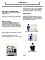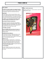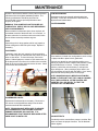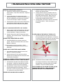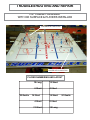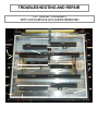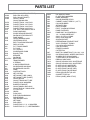
1
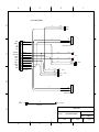
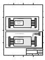
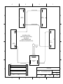
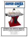
OWNERS AND SERVICE MANUAL
INNOVATIVE CONCEPTS IN ENTERTAINMENT INC.
10123 MAIN STREET, CLARENCE, NY 14031
SERVICE: 1–716–759–0360
FAX: 1–716–759–0884
E–MAIL: [email protected]
INNOVATIVE CONCEPTS IN ENTERTAINMENT, INC.
COPYRIGHT© 1983 BY INNOVATIVE CONCEPTS IN ENTERTAINMENT, INC.
ALL RIGHTS RESERVED
No part of this publication may be reproduced by any mechanical, photographic, or electronic process,
or in the form of a phonographic recording, nor may it be stored in a retrieval system, transmitted, or
otherwise copied for public or private use, without the permission of the publisher.
The SUPER CHEXX" game play, all graphic designs, this technical manual, its accompanying
schematic diagrams, and the trouble–shooting guide are protected by the new Copyright Act of 1976.
This Act provides for increased penalties for violating federal copyright laws. Courts CAN IMPOUND
infringing articles while legal action is pending. If infringes are convicted, Courts can ORDER
DESTRUCTION of the infringing articles.
In addition, the Act provides for payment of statutory damages of up to $50,000.00 in certain cases.
Infringes may also have to pay costs and attorneys’ fees, fines up to $25,000.00, and face an
imprisonment of up to one year.
I.C.E. will aggressively enforce its copyrights against any infringes. WE WILL USE ALL LEGAL
MEANS to immediately halt any manufacture, distribution or operation of a copy of any product made
by us. Anyone who purchases such copies risks forfeiting such a game.
U.S.A and foreign patents pending.
Published By:
INNOVATIVE CONCEPTS IN ENTERTAINMENT, INC.
10123 MAIN STREET
CLARENCE, NEW YORK 14031
Sales: 716 759–0370
Service: 716 759–0360
Email: [email protected]
www.icegame.com
TABLE OF CONTENTS
SUPER CHEXX" Game Play ........................... Page 4
Outstanding Features....................................... Page 6 & 7
Programming ................................................... Page 9
Game Assembly............................................... Page 10
Game Operation Test ....................................... Page 10
Maintenance .................................................... Page 11 & 12
Troubleshooting and Repair ............................. Page 13 THRU 17
Parts Listing ..................................................... Page 18
Schematics & Wiring Diagrams ........................ Page 19 THRU 25
Warranty .......................................................... Page 26
SUPER CHEXX" GAME PLAY
The SUPER CHEXX" Hockey game has been designed to resemble “real” hockey action. The object
of the game is to out–score your opponent before time runs out. Goals can be scored, with the game
continuing, until the “last puck in play” mode begins. When the last puck in play is scored, the game
ends.*
Example: If a score is 5–3, the last puck would result in a final score of 5–4 or 6–3.
*The exception to this rule occurs when a final puck would create a tie score.
Example: If the score is 2–1, the last puck might make the score 2–2. The game then automatically
goes into a “Sudden Death Overtime” mode and a final tie–breaking puck is ejected. The game will
end when the tie–breaking goal is scored.
The National Anthem, as well as the “Boo” sound and the “Ooh’s” and “Aah’s” add to the excitement of
playing SUPER CHEXX". The “Boo” button can be used to eliminate the National Anthem or to “Boo”
your opponent.
FEATURES
SUPER CHEXX" is a unique kinetic action hockey game,
using state–of–the–art components, electronics, and
advanced sound effects designed to closely resemble the
action, play, and feel of a real ice hockey game.
BREAK RESISTANT POLYCARBONATE DOME
The cover of this game is made of Lexan and will resist
breaking or cracking.
OVERHEAD SCOREBOARD
Scores and shots on goal are automatically tabulated by the
main processor unit and displayed here. Other features
include a running time clock, digital period display, and a
fluorescent light that produces minimal heat eliminating the
need for a fan.
UNIQUE SOUND EFFECTS
The sound effects in this game use state–of–the–art
components. Along with synthesized organ chants, this
game utilizes natural sounds actually recorded at a real
hockey game. Cheers can be noted when a goal is scored.
“Oh” sounds are produced when a puck enters the goalie’s
crease. Organ chants indicate period changes, last puck in
play mode, and sudden death overtime. A player can
actually “Boo” his opponent by pressing the “Boo” button
located at each end of the cabinet. Added to all these
sounds are a full–time background noise and a National
Anthem at the beginning of each game. A player can even
bypass the anthem if desired by pressing the “Boo” button.
CENTER ICE FACE OFF
This hockey game has a center ice face–off feature to add
to the realism of play. The puck is automatically ejected
once at the beginning of the game and once after each
goal. The puck may be ejected manually by pressing the
Boo/Eject buttons.
NEW ROD MATERIAL
Unlike previous games using rods that bend or break
easily, SUPER CHEXX" uses rods with a specially
developed fiberglass composite and exterior coating to
eliminate previous problems. These rods are immune to
even torturous abuse. They can bend almost 90 degrees
and still return straight time after time.
PLAYERS
LONG STICK PLAYER – 1 PER TEAM
GEAR / CLUTCH DESIGN
Each player on the game rotates on a 2.4:1 gear
mechanism, which utilizes a built–in clutch to allow opposing
players to strike or check one another without causing
damage to components. This feature also eliminates
intentional abuse. The gearing mechanism has been
designed to allow a player to rotate at maximum speed with
a minimum of effort.
SHORT STICK PLAYER – 4 PER TEAM
GOALIE – 1 PER TEAM
SUPER CHEXX" has realistic three–dimensional decorated
players to even further enhance realism and enjoyment of
the game.
FEATURES
GAME CABINET
The cabinet is of unitized construction using high quality
aluminum for strength, durability, and reliability. Threaded
inserts are used throughout the cabinet to make removal
and installation of parts in the cabinet fast and easy.
GAME BASE
The base design is a first in the game industry, using a
one–piece high impact plastic material versus conventional
wood or particleboard cabinetry. It is impervious to liquid
spills as well as many other typical abuses to which games
are subjected. The coloring has been molded into and
throughout the base, eliminating the effect of scratches
that harm the appearance and beauty of the game.
ADJUSTABLE TIME AND VEND PRICE
The time and vend price of the game can be adjusted
individually by switches on the main PC board. Time can
be set for two, three, four, or five minutes. The vend price
can be adjusted for $.25, $.50, $.75 or Free Play. Any
combination of time and price can be used.
ELECTRONICS ACCESS
All of the SUPER CHEXX" electronics are located on a
single PC board just inside the coin door. All IC’s are
readily accessible and mounted in high quality sockets
simplifying repairs.
SCOREBOARD ELECTRONICS
The scoreboard electronics, designed with state–of–the–
art circuitry, are very reliable. If any repair should be
necessary, the scoreboard can be replaced in less than (5)
minutes, eliminating costly down time.
SPEED OF PLAY
The play of the game is extremely fast. A unique ramp
construction eliminates dead spots and a special finish on
the highly polished playfield enhances the puck action.
The gearing ratio (described earlier), used for fast and
effortless play and rotation, provides for greater speed and
accuracy when shooting the puck.
QUICK ASSEMBLY
The game, designed in two pieces with an upper and a
lower half, can be assembled and connected in less than
(5)) minutes.
OVER / UNDER COIN DOOR
An industry standard over / under coin door is used in the
SUPER CHEXX" game.
PROGRAM BUTTON
SELECT BUTTON
STEP BUTTON
COIN 2 (COIN 1 EQUIVALENT) SET THIS VALUE TO 1 IF YOU
WISH THE VALUE TO BE THE SAME AS COIN 1 (IF YOU WISH
THE VALUE TO BE TWICE AS HIGH, SET TO 2. IF YOU WISH THE
VALUE TO BE THREE TIMES AS HIGH, SET TO 3, ETC&).
TIME UNITS PER PERIOD SET THIS VALUE TO 20 FOR
HOCKEY, OR 15 OR 30 FOR SOCCER.
TIME PER PERIOD SET THIS NUMBER FOR THE ACTUAL
AMOUNT OF SECONDS PER PERIOD. MULTIPLY THE NUMBER
OF PERIODS BY THE NUMBER OF SECONDS YOU CHOOSE FOR
OVERALL GAME TIME. EXAMPLE: 60 SECONDS X 3 PERIODS
(HOCKEY) - 3 MINUTE GAMES.
NUMBER OF PERIODS SET THIS NUMBER TO 3 FOR
HOCKEY, OR 2 OR 4 FOR SOCCER.
ANTHEM SET THIS VALUE TO 1 FOR THE CANADIAN
ANTHEM, OR 0 FOR THE U.S.A. ANTHEM.
AWARDS PER GAME SET THIS VALUE FOR THE NUMBER OF
TICKETS YOU WANT DISPENSED AT THE END OF THE GAME.
ATTRACT MODE INTERVAL SET THIS NUMBER FOR THE
AMOUNT OF TIME BETWEEN ATTRACT MODE SOUNDS.
SELECTING 0 WILL TURN THE ATTRACT MODE OFF.
2.
3.
4.
5.
6.
7.
8.
1.
COIN 1 (COINS PER CREDIT) SET THIS VALUE FOR
HOW MANY COINS IT WILL TAKE FOR 1 CREDIT.
GAME OPTIONS
note: pressing the start button will play 1 game without
advancing any counters. (or dispensing any tickets from the
optional ticket dispenser)
WHEN FINISHED, PRESS THE PROGRAM (PGM) BUTTON TO
RETURN TO GAME PLAY MODE.
PRESS THE STEP (STEP) BUTTON TO CHANGE THE VALUE OF THAT
PARTICULAR PROGRAMMING OPTION.
PRESS THE SELECT (SEL) BUTTON TO ADVANCE THROUGH THE
VARIOUS PROGRAMMING OPTIONS.
PRESS THE PROGRAM (PGM) BUTTON OF THE MAIN P.C. BOARD.
(THIS IS THE LEFTMOST OF THE 4 BUTTONS).
GAME ASSEMBLY
These steps should be followed for initial installation as well
as any time the game is dismantled and moved to a new location.
NSPECT INSIDE OF BASE
Check for loose parts or foreign material in bottom.
Inspect harnessing to speakers, coin door and coin
meter.
Inspect main PC Board for damage and familiarize
yourself with the 15–pin cabinet harness connector
and the 8–pin header for the scoreboard ribbon cable.
Place cabinet on Base oriented with hinge side of cabinet
opposite the coin door side of the Base.
Align the two so that the threaded cabinet mounting
inserts are visible through the access holes and the
mounting holes in the Base.
Install 4 Allen Head mounting bolts with fender
washers and tighten with provided T–handle wrench.
Connect 15–Pin Connector and Ribbon Cable connector to
main PC Board. The locking edge of the ribbon
cable connector should face the rear of the base.
Do not force or connect backwards or damage will
occur.
Plug game into 110 (optional 220) volt GROUNDED AC
outlet and turn on PC Board mounted power switch.
Warning: Failure to use a 3–prong grounded outlet
will void your warranty and may cause
harm to the game, yourself, and others.
Coin–up game and check for proper operation.
Finally, make sure your game is clean. A clean game
looks good, gets more play, and makes more money
than a dirty game.
GAME OPERATION – TEST
IMPORTANT: IF THE GAME FAILS TO PERFORM THE
FOLLOWING TESTS AS DESCRIBED, REFER TO THE
TROUBLESHOOTING SECTION.
Before starting a game, check to see that all players
rotate smoothly and that all rods move in and out
freely.
NOTE: THE GEAR BOXES REQUIRE 10 – 20
GAMES TO FULLY BREAK IN. SLIGHT
RESISTANCE WHEN ROTATING THE
PLAYERS ON A NEW GAME IS NORMAL.
Insert the proper number of coins to start game. The
National Anthem will begin and upon completion,
the puck will eject from the ejector chute. Shoot
the puck in each net several times to ensure
proper operation of the ejector.
Each time the puck enters the net; the score indicators
on both sides of the scoreboard should indicate
the goal scored. Continue scoring until the game
ends, checking the score indicators for proper
operation. Check to see that the score indicators
on both sides of the scoreboard are working
correctly.
Restart the game. Press the Boo/Eject button to
ensure the National Anthem is bypassed. The
puck should eject.
After the puck ejects, press the Boo/Eject buttons on
both ends of the game to ensure the “Boo” sound
is heard and eject Solenoid is activated.
Run the puck through each goal crease. The “Oh”
sound should be heard as the puck passes
through the crease. Note that a shot on a goal
has been registered.
MAINTENANCE
All parts in the SUPER CHEXX" Hockey Game have been
manufactured to the highest standards possible. The
following maintenance should be performed as
recommended to assure optimal performance and
longevity of the game.
WARNING: THIS GAME DOES NOT REQUIRE ANY
LUBRICATION. USE OF ANY OILS OR GREASE MAY
VOID YOUR WARRANTY.
COIN MECHANISMS
Mechanisms should be cleaned and adjusted when
necessary. Follow the manufacturer’s instructions on
adjustment and maintenance.
PLAYER WASHERS
Most mechanical maintenance jobs, when required, will
necessitate removal of the dome and / or ice surface. In
all cases, when the ice surface must be removed, follow
the ice surface removal procedure as given.
PUCK
Inspect the puck for large gashes, which may impede a
smooth rolling action down the puck ramps. Replace if
necessary.
PUCK RAMPS
Periodically check the puck ramps for dirt accumulation
and / or other objects or materials that may cause the puck
action to slow down. To clean the ramps, remove the
goalies. Slide all players to center ice (this saves time, as
all the players and ice surface do not have to be removed).
Bend up the ice on either end and remove the nets. Clean
out the tracks and reassemble.
These washers, located over each gearbox, serve to keep
the players shafts in place in their gearboxes.
Extreme care should be exercised when pulling out or
pushing in players because a washer that falls into a track
can be bothersome to remove. To help eliminate this
problem, push all the rods all the way in, and pull the
player straight out. When pushing a player back in, be
sure the gearbox is lined up with the shafts. If not, slowly
rotate the rod while pushing down on the player.
NOTE: WASHERS SHOULD BE REPLACED WHEN
WORN TO THE POINT THAT THEY CAN NO LONGER
HOLD THE PLAYERS IN. AFTER PLAYERS ARE
INSERTED, PULL UP GENTLY TO TEST THE
STRENGTH OF THE WASHERS.
SCOREBOARD LIGHTS
PLAYER WASHER
Replacement is advised when necessary. Remove the
four screws on the light diffuser and pull out the bulb.
Insert the new bulb and reassemble.
NOTE: TIE WRAPS HAVE BEEN USED TO SECURE
THE FLOURESCENT LIGHT AGAINST SHIPPING
DAMAGE AND ABUSE ON LOCATION. IT IS
RECOMMENDED THAT THESE BE REPLACED AFTER
A NEW LIGHT IS INSTALLED.
SOUND EFFECTS
Periodically test the sound effects, sensors, and the “Boo”
button to ensure the proper functions. Test for National
Anthem bypass.
MAINTENANCE
ICE SURFACE
The ice surface should be cleaned as needed, using
Windex", Fantastic", or a comparable product. Apply
liberally to a lint–free cloth, wipe surface thoroughly, and
let dry. For a “faster” ice surface, dust lightly with Pledge"
and let dry.
DOME
The Lexan dome should be cleaned as needed, using a
furniture polish type of cleaner. Apply to a lint–free cloth
and wipe dome thoroughly.
NOTE: PLEDGE" IS RECOMMENDED. ALWAYS TEST
THE CLEANER YOU INTEND TO USE ALONG THE
FLANGE TO MAKE SURE THE CLEANER WILL NOT
HARM THE DOME FINISH. TO REMOVE SCRATCHES,
A SPECIAL SCRATCH REMOVER FORMULATED FOR
LEXAN SHOULD BE OBTAINED.
Start the game and observe operation. Check for foreign
particles under the ejector wire. The entire bracket
assembly can be bent to correct excessive lean in one
direction. Be sure all parts work freely. Check by pushing
the solenoid plunger only, to see that the ejector lifts up
about 3/8” from the cabinet bottom. If more or less
movement is noted, the ejector wire can be bent forward or
backward where it meets the plunger to obtain proper
operation.
Excessive random angle ejections can be straightened by
tightening the pivot screw. An ejector that sticks in the up
position can be fixed by loosening the pivot screw.
PLAYERS
Periodically inspect the players for appearance or possible
damage. Replace when necessary.
EJECTOR WIRE
VIEW OF PLAYER AFTER INSTALLATION
PIVOT SCREW
EJECTOR MECHANISM
Periodically test the mechanism by scoring goal and
observing puck ejection. If puck fails to eject, does not
clear ice surface, or ejects with excessive lean in one
direction, the mechanism is not working correctly. Open
the dome and remove the ice surface.
NOTE: BE CAREFUL NOT TO LOSE THE FLAT
WASHERS.
MAINTENANCE
GEARBOXES
PUCK CHUTE
Gearboxes should be inspected periodically to ensure
smooth operation. Gearbox tracks should be kept as
clean as possible. If a gearbox seems to rotate stiffly, first
check to see that a rod collar is not pushed up tightly
against it (this can happen if a grip comes off a rod and a
gearbox hits a solid object, usually on defensemen). Back
off a collar from a gearbox by loosening, moving, and
retightening.
Clean periodically to ensure a good sliding surface. Check
for cracks. Small cracks can be glued with a C/A
adhesive. Large cracks require changing the part.
GOALIE MECHANISMS
Check for smooth operation.
NOTE GEARBOXES ARE LUBRICATED FOR LIFE AND
SHOULD NOT BE OILED OR GREASED.
RODS
ROD BEARINGS
Check periodically for cracks and gouges. Replace if
necessary. Clean Mineral Spirits or Paint Thinner. Do not
allow cleaner to contact the Dome, as it will damage the
Dome.
Check once a year for excessive wear. Replace when
necessary.
TRACKS
Check periodically. Clean by pushing a rag along the
length of the track.
SENSORS
These should be tested periodically by moving the puck
over the “Oh” sensors and through the score sensors.
TROUBLESHOOTING AND REPAIR
PUCK WILL NOT EJECT
PUCK TAKES TWO OR THREE TIMES TO EJECT
For some ejection problems the ice surface may have to
be removed.
1. Opening the dome and sliding all of the players to
the center ice can correct dirt in the puck ramps.
Next, remove the goalies one at a time, bend up
the ice surface and clean the ramps. Assemble in
the reverse order.
A leaning puck ramp can be corrected by observing
which way the puck leans as it rolls down the ramp
and bending the ramp to one side or the other,
back by the net chute assembly.
A puck hitting the ice surface can be corrected by first
making sure the ice surface is in place. If it is in
place, observe which way to bend the retainer
chute assembly to line up with the opening in the
surface.
To determine if the ejector wire is misaligned, first
remove the ice surface and then start the game.
Look straight down the ejector chute and observe
how the puck ejects. If the puck consistently hits
one side of the chute, the ejector wire should be
adjusted. Refer to the maintenance section for
specific directions, under “Ejector Mechanism.”
PUCK
RAMP
3. A puck ramp may become pushed up during
shipping or moving. Just push it back down in the
retainer/chute with a pencil or screwdriver.
EJECTOR CHUTE
4. A unique electronic circuit incorporated on the
main PC Board prevents the eject solenoid from
burning out. If a solenoid problem is suspected,
check for a pulse of about 12 volts at the solenoid.
Then remove the wires to the solenoid and check
that the coil is not open or shorted. A good
solenoid will read between 3–4 ohms.
NOTE: REPLACE THE SOLENOID ONLY AFTER
DETERMINING WITH AN OHM/VOLT METER THAT THE
SOLENOID WAS RECEIVING POWER.
PUCK EJECTOR SOLENOID
TROUBLESHOOTING AND REPAIR
GEARBOX IS DIFFICULT TO TURN
1. A gearbox–coupling collar may have been forced
against a gearbox causing uneven or difficult
turning. The usual cause for this is a handle grip
coming off a rod and allowing the gearbox to hit
either another gearbox or a cabinet end. To
repair, simply loosen the collar and back it away
from the gearbox between 1/32” and 1/16”.
NO LIGHT IN GAME
1. The light bulb may be burned out. Open dome
see if bulb is burned out. Replace if necessary.
2. A loose scoreboard connector is not likely to affect
the bulb without affecting some other component
in the scoreboard. However, make sure the
connectors are firmly seated.
PLAYERS RUN INTO THE END OF THEIR SLOTS
PLAYER ROD & GEAR BOX SHAFT MUST MEET
IN THE CENTER OF COLLAR SLOT
1. A rod collar slipping may cause a player to hit the
end of a slot in an ice surface. Open the game
and rotate the rod until you can see the rod and
gearbox touch, through the slot in the collar. If the
rod and the gearbox do not touch, loosen the
collar make sure the rod and gear box coupler
touch, and retighten the gearbox. Be sure to
leave 1/32” to 1/16” between the collar and the
gearbox body.
SCORE INDICATORS DO NOT WORK PROPERLY
1. A bad LED may cause malfunction. Replace the
scoreboard and run electronic tests on the faulty
unit.
Retighten.
2. Gear teeth being stripped out will generally cause
binding at certain points of rotation. This situation
should not occur until many games have been
played. However, to check for bad gears, first
remove the gearbox from the game. Loosen the
gearbox collar and slide out the gearbox. If teeth
on gears are worn out, replace the gearbox.
3. A worn gear bearing can cause a gearbox to work
improperly. If you suspect a gear problem, first
remove the gearbox from the game. If no
problems are visible, disassemble the gearbox. If
a worn bearing is found, replace the gearbox.
GAME LIGHTING DIM
1. The scoreboard bulb may be burned out. Open
the dome and see if the bulb appears to be burned
out while the game is plugged in. Unplug the
game. Remove the screws holding the right
diffuser in place. Replace the light bulb and
reassemble.
2. Very low AC power will cause poor lighting. To
test, use a voltmeter on the suspect line to
determine voltage. A CHEXX" game hooked up to
a line with too many other games may experience
this difficulty. Move the game to its own AC line if
this problem is experienced.
2. A bad scoreboard chip may cause indicator
malfunction. Replace the scoreboard and run
electronic tests on the faulty unit.
3. A loose connection may cause malfunction.
Check and repair as necessary.
GAME LOSES PLAY SEQUENCE. GIVES FALSE
SCORE, WILL NOT START WHEN MONEY IS
INSERTED
1. Although game is protected against static
electricity, an unusually large shock will cause the
microprocessor to lose sequence. To correct the
problem, turn off power and turn it back on to
reset electronics.
2. A game plugged into an ungrounded outlet has no
protection from static electricity. A large enough
shock may destroy the IC chips. Electronic tests
may be run to determine the fault. Repair as
necessary .
TROUBLESHOOTING AND REPAIR
COINS NOT REGISTERED CORRECTLY
1. A bad micro–switch may be a problem due to
internal failure. Test with an ohmmeter. Replace if
necessary.
2. Loose connections may cause money to be
registered improperly. Check the connectors from
the coin mechanisms, as well as the connectors
on the main PC Board. Repair if necessary.
3. A bad capacitor (CZ5) on the main PC Board may
cause bounce problems with the micro–switch.
Run electronics tests to determine the problem.
1. Check the audio IC chips on the main PC Board.
Replace any defective parts.
2. A faulty volume control is a possible cause for
intermittent sound. Rotating the volume control
will usually show a problem. Many times, the
problem can be corrected by cleaning with a
commercially available switch cleaner.
3. A bad speaker connection to the main PC Board
may be the problem. Check and repair as
necessary.
NO “OH” SOUNDS OR REPEATED “OH” SOUNDS
1. Short or open circuits in the harness or one of the
reed switches on the “Oh” sensors are the most
common problems. Repair as necessary.
2. A bad IC chip on the main PC Board may cause
problems. Run electronics tests. Repair defective
components.
SCORE IS NOT REGISTERED–NO CHEER
1. A bad Reed Switch may cause a goal not to
register. Disconnect and test with an ohmmeter.
Replace if defective.
PLAYERS RUB ON THE SIDES OF THEIR SLOTS
1. On rare occasions a track may become bent,
forcing the player to work improperly. If, when the
ice surface is properly located, you can see the top
of an aluminum track, the track must be bent.
A bad connection could be a problem. Check
associated harnessing and connectors with an
ohmmeter.
SCORE IS NOT REGISTERED–GAME CHEERS
1. A scoreboard connector may be loose or bad.
Repair or correct as necessary.
2. A bad scoreboard IC chip may be a problem.
Replace the scoreboard and run electronics tests
to determine the problem.
SCORE AND CHEERING KEEPS REPEATING FOR ONE
TEAM WITH NO GOALS ACTUALLY BEING SCORED
1. A Reed Switch shorted to the cabinet will cause
this problem. Usually an exposed wire touching
the cabinet will be the cause of the problems.
2. A Reed Switch, always closed, can be tested by
first disconnecting it from the board. Use an
ohmmeter to see if the switch is always closed. If
it is, replace the score Reed Switch.
SOUND GOES LOW OR GOES ON AND OFF
NOTE: ALUMINUM TRACK IS NOT VISIBLE IN PHOTO.
Use a large screwdriver or other suitable object,
and gently pry in the desired direction to obtain
clearance. Check for smooth operation.
NOTE: BE SURE NOT TO GOUGE THE SIDE OF THE
CHANNEL WHEN PRYING. A RAG SHOULD BE
WRAPPED AROUND YOUR SCREWDRIVER.
TROUBLESHOOTING AND REPAIR
TOP CABINET ASSEMBLY
WITH ICE SURFACE & PLAYERS INSTALLED
PLAYER WITH LONG STICK
PLAYER WITH LONG STICK
PLAYER NUMBERING AND LAYOUT
30 Goalie
18 Long
12 Short
6 Short
4 Short
14 Short
14 Short
4 Short
6 Short
12 Short
18 Long
30 Goalie
TROUBLESHOOTING AND REPAIR
TOP CABINET ASSEMBLY
WITH ICE SURFACE & PLAYERS REMOVED
HINGE
SCOREBOARD CABLE
“BOO”
RIGHT
GRIP
LEFT
LONG COLLAR
DEFENSE
GRIP
SOLENOID
COLLAR
EJECTOR CHUTE
GOALIE
COLLAR RUBBER
DEFENSE
CENTER
SHORT
RIGHT
CABINET
“BOO”
LEFT
ROD BEARING
PARTS LIST
745
1002X
1003X
1004X
1007X
1008X
1009X
1010X
1012
1013
1014
1016
1018
1019
243X
248
249
2001
2003
2007
SC2070X
2071
2368
341
342
3001
3002
3002A
3004
3005
3006
3007
3008
3009
3010A
3010X
3011
3012X
3013X
3014
3016
3017X
3018
3020
SK321
SK322
DECAL (CABINET) (NEW STYLE)
ROD COLLAR (LONG)
ROD COLLAR (SHORT)
GOALIE TRACK
GOALIE SWING ARM
PLAYER TRACK 1 & 8 EACH
PLAYER TRACK 2 & 7 EACH
PLAYER TRACK 3 & 6 EACH
PLAYER TRACK 4 & 5 EACH
CTR. EJECT RETAINER CHUTE
PUCK RAMP ASSY.
SCORE SENSOR BRACKET
SOLENOID STOP BRACKET
DOME HINGE
GOALIE BEARING ASSY.
CENTERMAN STOP
EJECT SOLENOID BRACKET
DISPLAY PCBA
PL 7 TRANSFORMER
PL 7 BULB
PL 7 SOCKET
SCOREBOARD PCBB
BOO BUTTON
SPEAKER
SOLENOID
MAIN PCBA
TRANSFORMER
IC EPROM
IC MICROPROCESSOR
SCOREBOARD HOUSING
SCOREBOARD COVER
DOME
CHUTE/NET ASSY.
NET CURTAIN
NET MOUNT TUBE (LONG)
NET MOUNT TUBE (SHORT)
GOALIE BLOCK
GOALIE TRACK MNT. TUBE
PLAYER LOCK WASHERS
BUMPER STANDOFF
GOALIE KNOB & ROD ONLY
GOALIE ROD W / SWING ARM.
“D” FLECTOR
GEARS
PUCK ASSY.
EJECTOR ARM BUSHING
ROD BEARING
GRIP BUMPER ASSY.
NET RAMP
ROD GRIPS
PLAYER ROD 1, 5, 6, 10 WINGERS
PLAYER ROD 2, 4, 7, 9 DEFENSEMEN
3025X
3035
3036
4002
4003
4004
5003
5005
5011
6001
6001B
6006
6010
6011
6021
6024
6025
6036
6067
6287
6706X
6707X
6707A
6711X
7001X
7002X
7005A
7007B
7008A
7010B
7025B
7030X
7118
ICE SURFACE ASSY.
PLAYER ROD WASHERS
DOME WASHERS
GOALIE BUMPER STOPS
CABINET GASKET PER PC. (10 FT.)
COLLAR RUBBER
SPEAKER GRILL
EJECTOR ARM
EJECT. SOLENOID SPRING
DOME FASTENER
DOME BOLT ALLEN WRENCH
1/4 – 3/8 SHOULDER BOLT
GOAL. CLUTCH–O–RING
GOAL. ROD WASHER
SOLENOID RIVET
DEFENSEMAN STANDOFF BOLT
VINYL STANDOFF TUBING
COLLAR ALLEN WRENCH
COLLAR SCREW
FENDER WASHER
COTTER PIN
BASE TO CABINET BOLT 5/16–18 X 1 3/4
OH SENSOR ASSY. W/REED SWITCHES
SCORE/EJECT SENSOR ASSY.
1” REED SWITCH–SCORE/EJECT
RIBBON CABLE ASSY.
GOALIE & BLOCK ASSY. WHITE/BLUE
GOALIE & BLOCK ASSY. WHITE/RED
PLAYER (LS/SC) WHITE/RED
PLAYER (LS/SC) WHITE/BLUE
PLAYER (SS/SC) WHITE /RED
PLAYER (SS/SC) WHITE/BLUE
DECAL (BOO/EJECT) BLACK
GIGARETTE DECAL
DECAL (BASE) (NEW STYLE)
4
3
2
1
D
D
#279X-BASE HARNESS
**DOES NOT INCLUDE POWER CORD.
C
COIN 2
+12v
CCNTACN
COIN COM
+12v
FRAME
GND
COIN 1
ACH
GND
SPK RT.
1
2
3
4
5
6
7
8
9
10
11
12
yellow
36 "
BLACK
WHITE
black
RED
GREEN/YELLOW
36 "
brown
BLACK
GREEN
BLUE
28 "
6 "
.250 FLAG
#648
COIN 2
.250 FLAG
#648
12 "
28 "
36 "
COIN COM
black
20 "
brown
#PC20217
.250 FLAG
#648
BLACK
30 "
30 "
COIN 1
#2558
22 "
GREEN
12 PIN PLUG #2106
SPLIT PIN #2100
PIN 4+10 USE PART 20-14 AWG #8260
BLUE
C
#HD20224
5v COUNTER
RED
#651
#638
SPEAKER
#638
SPEAKER
22 "
#651
9"STRIP
#SC2027X-POWER
CORD
#PC20217
20ft.
#CC2027
B
B
SUPER CHEXX
TITLE
A
QTY 1
PER GAME
DESCRIPTION
3/1/00
DATE
4
3
#279X-BASE HARNESS
#SC2027X-POWER CORD
2
REVISED
6/27/01
FILENAM
E
DRAWN BY
PAGE
1
A
SC_VSD..VSD
CHERYLZ1
1 OF 4
4
3
2
1
#278X-CABINET HARNESS
D
75 "
yellow
gray
.250 #653T
84 "
SOG EJECT +
+12v
GND
+12v
C
1
2
3
4
5
6
7
8
9
10
11
12
13
14
15
BOO COM
GOAL COM
EJECTBOO 1
BOO 2
GOAL 1
GOAL 2
SOG1
SOG2
D
.250 #653T
red
brown
red-red
ORANGE
2
1
#2089R-2 PIN RT< CONN
lt. blue *2
yellow *2
ORANGE
blue
green
gray
white
brown
black
88 "
lt. blue
#651
C
BOO 1
88 "
blue
90 "
72 "
15 PIN PLUG #2144
SPLIT PIN #2100
yellow
green
lt.blue
white
#651
ORANGE
ORANGE
#651 EJECT+
#651
#651
BOO 2
#651
.250 #653T
GOAL 2
.250 #653T
B
B
75 "
red
black
2
1
#2089R-RT<2 PIN CONN
TO
CASHBOX
#639
105 "
14 AWG GREEN/YELLOW
PART OF #278X
#8068
TO HINGE
SUPER CHEXX
TITLE
A
DESCRIPTION
#278X-CABINET HARNESS
FILENAM
E
DRAWN BY
3/1/00
DATE
4
3
2
REVISED
6/27/01
PAGE
1
A
SC_VSD..VSD
CHERYLZ1
2 OF 4
4
3
2
1
D
D
#6711X- RIBBON CABLE ASY
#2239-KEY
1
2
3
4
5
6
7
8
9
10
C
#2239-KEY
60" OF RIBBON CABLE #6711
#2239-KEY
1
2
3
4
5
6
7
8
9
10
20 " OF TAPE
**START 6" FROM THE
CONNECTOR
#2104-10 PIN MTA CONN
C
#2239-KEY
#2104-10 PIN MTA CONN
1
2
#6711XO-OLD STYLE RIBBON CABLE ASY
2 PIN CAP #2181
MALE14 AWG PIN #2422
B
#2239-KEY
1
2
3
4
5
6
7
8
9
10
#2239-KEY
60" OF RIBBON CABLE #6711
1
2
3
4
5
6
7
8
9
10
20 " OF TAPE
**START 6" FROM THE
CONNECTOR
#2104-10 PIN MTA CONN
B
#2239-KEY
#2239-KEY
#2104-10 PIN MTA CONN
SUPER CHEXX
TITLE
A
FILENAM
E
DESCRIPTION
DRAWN BY
3/1/00
DATE
4
3
2
REVISED
6/27/01
PAGE
1
A
SC_VSD..VSD
CHERYLZ1
3 OF 4
4
3
2
#281XS-SHORT HARNESS
P2
D
1
P1
D
#243XDISPLAY ASY
#243XDISPLAY ASY
#281XS-SHORT HARNESS
P1
P2
P2
P1
C
C
#343-OVERLAY (GOAL)
#343A-OVELAY (SHOTS ON GOAL)
#341-HOUSING
#342-SCOREBOARD COVER
#657-SPIDER NUT (SPIDER MTG.PLATE)
#243XDISPLAY ASY
#243XDISPLAY ASY
#249-PL7 BULB
PLAYFIELD
BULB
P1
P2
B
B
#2001X-INTERFACE
PCBA ASY
#281XS-SHORT HARNESS
A
1
2
3
4
5
6
7
8
brown
red
orange
1
2
3
4
5
6
7
8
yellow
green
dk.blue
7" FOR
#281XL
#2092-8-P IDC
5" FOR
#281XS
#2092-8-P IDC
4
3
#281XS-LONG HARNESS
J2
J3
SUPER CHEXX
TITLE
DESCRIPTION
#341X-SCOREBOARD HOUSING
FILENAM
E
DRAWN BY
3/1/00
DATE
2
REVISED
6/27/01
PAGE
1
A
SC_VSD..VSD
CHERYLZ1
4 OF 4
Warranty
I.C.E warrants all components in the SUPER CHEXX" game to be free of defects in
materials and workmanship for a period of ninety days from the date of purchase.
This warranty does not cover items damaged due to normal wear and tear,
subjected to abuse, improperly assembled by the end user, modified, repaired, or
operated in a fashion other than that described in the service manual.
If your SUPER CHEXX" game fails to conform to the above–mentioned warranty,
I.C.E.'s sole responsibility shall be at its discretion to repair or replace any defective
component with a new or remanufactured component of equal to or greater O.E.M.
specification.
I.C.E. will assume no liability whatsoever, for costs associated with labor to replace
defective parts, or travel time associated therein.
I.C.E.'s obligation will be to ship free of charge, replacement parts by U.P.S. Ground,
U.S. mail, or other comparable shipping means. Any express mail or overnight
shipping expense is at the cost of the purchaser.
Products will be covered under warranty only when:
·
The serial number of the game with the defective parts is given.
·
The serial number of the defective part, if applicable, is given.
·
Defective parts are returned to I.C.E., shipping pre–paid, in a timely fashion, if
requested by I.C.E.
·
A copy of the sales receipt is available as proof of purchase upon request of
I.C.E.
I.C.E. distributors are independent, privately owned and operated. In their judgment,
they may sell parts or accessories other than those manufactured by I.C.E. We
cannot be responsible for the quality, suitability, or safety of any non–I.C.E. part, or
any modification, including labor, which is performed by such a distributor.