1
2340359003
Operator's Manual
20.0=VOLT LITHIUM=ION CORDLESS
1/2-in. Hammer Drill/Driver
Model No.
320.29004
•
•
•
•
•
•
WARRANTY
SAFETY
ASSEMBLY
DESCRiPTiON
OPERATION
MAINTENANCE
_IL WARNING:
To reduce the risk
of injury, the user must read and
understand the operator's manual
before using this product.
CHARGE BATTERY
BEFORE FIRST USE
Sears Brands Management Corporation
Visit the Craftsman web page: www.sears.com/craftsman
Save this manual
2340359003
for future
reference
•
Warranty ......................................................................................................................................
2
•
Introduction
2
•
Safety Symbols ........................................................................................................................
3-4
•
General Safety Rules ...............................................................................................................
5-7
•
Specific Safety Rules ..................................................................................................................
•
Safety Rules for Charger .........................................................................................................
•
Description ............................................................................................................................
•
Assembly ....................................................................................................................................
•
Operation ..............................................................................................................................
12-22
•
Maintenance .........................................................................................................................
23-24
•
Exploded View and Parts List ..............................................................................................
25-27
•
Sears Repair Parts Phone Numbers ..........................................................................
.................................................................................................................................
7
8-9
10-11
11
Back Cover
kV,
Vl:l -']-'_:I _ //h'd
TWO YEAR LIMITED WARRANTY
ON CRAFTSMAN
® PROFESSIONAL
TOOL
If this Craftsman Professional tool fails due to a defect in material or workmanship, RETURN
IT TO THE NEAREST SEARS STORE OR OTHER CRAFTSMAN OUTLET IN THE UNITED
STATES for free replacement during the first year from the date of purchase,
during the second year from the date of purchase.
This warranty does not include expendable
parts such as lamps, batteries,
and for free repair
bits or blades.
This warranty gives you specific legal rights, and you may also have other rights which vary from
state to state.
Sears, Roebuck
and Co., Hoffman
Estates,
IL 60179
II_/ d-'{o]_ll_o,_i[o]_ I
SAVE THESE INSTRUCTIONS!
READ ALL INSTRUCTIONS!
This Hammer Drill/Driver has many features for making its use more pleasant and enjoyable.
Safety, performance and dependability have been given top priority in the design of this product
making it easy to maintain and operate.
A
_lk
WARNING:
known
ductive
Some
to the state
harm.
dust created
of California
by using
to cause
power
cancer
tools
and
contains
birth
defects
chemicals
or other
repro-
Thepurpose
ofsafety
symbols
istoattract
yourattention
topossible
dangers.
Thesafety
symbols
andtheexplanations
withthem
deserve
yourcareful
attention
andunderstanding.
The
symbol
warnings
DONOT
bythemselves
eliminate
anydanger.
Theinstructions
andwarnings
theygivearenosubstitutes
forproper
accident
prevention
measures.
_0kWARNI NG: BE SURE to read and understand all safety alert symbols such as
"DANGER", "WARNING" and "CAUTION" BEFORE using this product. Failure to follow all
instructions may result in electric shock, fire and/or serious personal injury.
SYMBOL
SIGNAL
MEANING
,_
DANGER:
situation,
if not avoided,
will result
Indicates which,
an imminently
hazardous
in death or serious injury.
_,
WARNING:
situation,
if not avoided,
Indicates which,
a potentially
hazardouscould
result in death or serious injury.
_,
CAUTION:
situation,
if not avoided,
Indicates which,
a potentially
hazardous may result
in minor or moderate injury.
CAUTION:
(Without Safety Alert Symbol) Indicates
a situation that may result in property
damage.
_WARNING:
To ensure safety and reliability, all repairs should be performed
qualified service technician at Sears Service Center.
by a
_DkWARNING:
The operation of any power tool can result in foreign objects
being thrown into your eyes, which can result in severe eye damage. Before
beginning power tool operation, always wear safety goggles or safety glasses
with side shields and a full face shield when needed. We recommend Wide
Vision Safety Mask for use over eyeglasses or standard safety glasses with side
shields. Always use eye protection which is marked to comply with ANSI Z87.1.
SAVE
THESE
INSTRUCTIONS
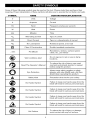
Some of these following symbols may be used on this tool, Please study them and learn their
meaning, Proper interpretation of these symbols will allow you to operate the tool better and safer,
SYMBOL
NAME
DESIGNATION/EXPLANATION
V
Volts
Voltage
A
Amperes
Current
Hz
Hertz
Frequency (cycles per second)
W
Watt
Power
min
Minutes
"k..,
Alternating
Time
Current
Type of current
---'==
Direct Current
Type or a characteristic
no
No Load Speed
Rotational speed, at no load
[]
.../min
Class II Construction
Double-insulated
construction
Per Minute
Revolutions, strokes, surface speed,
orbits, etc. per minute
Wet Conditions Alert
locations.
Do not expose to rain or use in damp
Read The Operator's
Manual
read and understand operator's manual
To reduce the risk of injury, user must
before using this product.
Eye Protection
_.
of current
glasses with side shields and a full face
Always wear safety goggles or safety
shield when operating this product.
Safety Alert
Precautions
that involve your safety.
No Hands Symbol
blade
in serious
injury.
Failure will
to result
keep your
hands personal
away from
the
No Hands Symbol
blade
Failure will
to result
keep your
in serious
hands personal
away from
injury.
the
No Hands Symbol
blade
Failure will
to result
keep your
in serious
hands personal
away from
injury.
the
No Hands Symbol
blade
Failure will
to result
keep your
in serious
hands personal
away from
injury.
the
Hot Surface
To reduce
the with
risk any
of injury
or damage,
avoid
contact
hot surface.
4
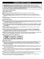
_WARNING:
READ
AND UNDERSTAND
ALL INSTRUCTIONS.
Failure to follow
all
instructions listed below may result in electric shock, fire and/or serious personal injury.
The term "power tool" in all of the warnings listed below refer to mains-operated (corded)
power tools or battery-operated (cordless) power tools.
SAVE THESEINSTRUCTIONS
WORK AREA SAFETY
•
Keep work area clean and well lit. Cluttered or dark areas invite accidents,
•
Do not operate power tools in explosive atmospheres, such as in the presence of
flammable
liquids, gases or dust. Power tools create sparks which may ignite the dust or
fumes,
•
Keep children
to lose control,
ELECTRICAL
•
and bystanders
away while operating
a power tool. Distractions
cause you
SAFETY
Power tool plugs must match the outlet. Never modify the plug in any way. Do not use
any adapter plugs with earthed (grounded) power tools. Unmodified plugs and matching
outlets will reduce the risk of electric shock.
• Avoid body contact with earthed (grounded)
surfaces such as pipes, radiators, ranges
and refrigerators. There is an increased risk of electric shock if your body is earthed
(grounded).
•
Do not expose power tools to rain or wet conditions.
increase the risk of electric shock,
Water entering a power tool will
•
Do not abuse the cord. Never use the cord for carrying, pulling or unplugging the
power tool. Keep cord away from heat, oil, sharp edges or moving parts. Damaged
entangled cords increase the risk of electric shock.
or
• When operating a power tool outdoors, use an extension cord suitable for outdoor use.
Use of a cord suitable for outdoor use reduces the risk of electric shock.
•
Use battery only with charger
listed.
BATTERY
PACK
CHARGER
CHARGER
320.25708
320.25709
320.257091
PERSONAL SAFETY
• Stay alert, watch what you are doing and use common sense when operating a power
tool. Do not use a power tool while you are tired or under the influence of drugs,
alcohol or medication. A moment of inattention while operating power tools may result in
serious personal injury.
•
Use safety equipment. Always wear eye protection. Safety equipment such as dust masks,
non-skid safety shoes, hard hat or hearing protection used for appropriate conditions will
reduce personal injuries,
• Avoid accidental starting. Ensure the switch is in the off position before plugging in.
Carrying power tools with your finger on the switch or plugging in power tools that have the
switch on invites accidents,
•
Remove any adjusting key or wrench before turning the power tool on. A wrench or key
left attached to a rotating part of the power tool may result in personal injury,
•
Do not overreach. Keep proper footing and balance at all times.
control of the power tool in unexpected situations,
This enables better
•
Dress properly. Do not wear loose clothing or jewelry. Keep your hair, clothing and gloves
away from moving parts. Loose clothes, jewelry or long hair can be caught in moving parts,
•
If devices are provided for the connection of dust extraction and collection facilities,
ensure these are connected and properly used. Use of these devices can reduce dustrelated hazards,
•
Do not wear loose clothing or jewelry.
hair can be drawn into air vents,
•
Do not use on a ladder or unstable support. Stable footing on a solid surface enables
better control of the power tool in unexpected situations,
Contain
long hair. Loose clothes, jewelry
or long
POWER TOOL USE AND CARE
•
Do not force the power tool. Use the correct power tool for your application.
power tool will do the job better and safer at the rate for which it was designated,
The correct
•
Do not use the power tool if the switch does not turn it on or off. Any power tool that
cannot be controlled with the switch is dangerous and must be repaired,
•
Disconnect the plug from the power source and/or the batter pack from the power tool
before making any adjustments, changing accessories or storing power tools. Such
preventive safety measures reduce the risk of starting the power tool accidentally.
• Store idle power tools out of the reach of children and do not allow persons unfamiliar
with the power tool or these instructions to operate the power tool. Power tools are
dangerous in the hands of untrained users,
•
Maintain power tools. Check for misalignment or binding of moving parts, breakage of
parts and any other condition that may affect the power tool's operation. If damaged,
have the power tool repaired before use. Many accidents are caused by poorly maintained
power tools,
•
Keep cutting tools sharp and clean. Properly maintained
edges are less likely to bind and are easier to control,
•
Use the power tool, accessories and tool bits etc., in accordance with these
instructions and in the manner intended for the particular type of power tool, taking in
account the working conditions and the work to be performed. Use of the power tool for
operations different from those intended could result in a hazardous situation,
cutting tools with sharp cutting
BATTERY TOOL USE AND CARE
•
Ensure the switch is in the off position before inserting
battery pack. Inserting the
battery pack into power tools that have the switch on invites accidents,
•
Recharge only with the charger specified by the manufacturer. A charger that is suitable
for one type of batter pack may create a risk of fire when used with another battery pack,
•
Use power tools only with specifically designated
packs may create a risk of injury and fire,
battery packs. Use of any other battery
• When battery pack is not in use, keep it away from other metal objects like paper clips,
coins, keys, nails screws or other small metal objects that can make a connection from
one terminal to another. Shorting the battery terminals together may cause burns or a fire,
•
I
Under abusive conditions, liquid may be ejected from the battery, avoid contact. If
contact accidentally occurs, flush with water. If liquid contacts eyes, additionally seek
medical help. Liquid ejected from the battery may cause irritation or burns,
&WARNING:
To reduce the risk of injury, user must read instruction manual
I
[_ _ _I _ ;_;1a![.,,.']';I
;I :a/L'4I-'t_
SERVICE
•
Have your power tool serviced by a qualified repair person using only identical
replacement parts. This will ensure that the safety of the power tool is maintained,
•
When servicing a power tool, use only identical replacement parts. Follow instructions
in the Maintenance section of this manual. Use of unauthorized parts or failure to follow
Maintenance instructions may create a risk of shock or injury,
•
Use auxiliary handle supplied with the tool. Loss of control can cause personal injury,
•
Hold power tools by insulated gripping surfaces when performing an operation where
the cutting tool may contact hidden wiring or its own cord. Contact with a "live" wire will
also make exposed metal parts of the tool "live" and shock the operator,
•
Use clamps or another practical way to secure and support the workpiece to a stable platform.
Holding the work by hand or against your body leaves it unstable and may lead to loss of control,
•
Know your power tool. Read operator's manual carefully. Learn its applications and
limitations, as well as the specific potential hazards related to this tool. Following this
rule will reduce the risk of electric shock, fire or serious injury.
•
Always wear safety glasses with side shields. Everyday glasses have only impact resistant
lenses. They are NOT safety glasses. Following this rule will reduce the risk of eye injury,
•
Protect your lungs. Wear a face or dust mask if the operation
will reduce the risk of serious personal injury,
•
Protect your hearing. Wear hearing protection during extended
Following this rule will reduce the risk of serious person injury,
•
Battery
always
battery
electric
•
Do not place battery tools or their
explosion and possibly injury,
•
Do not crush, drop or damage battery pack. Do not use a battery pack or charger that
has been dropped or received a sharp blow. A damaged battery is subject to explosion,
Properly dispose of a dropped or damaged battery immediately.
•
Batteries vent hydrogen gas and can explode in the presence of a source of ignition
such as a pilot light. To reduce the risk of serious personal injury, never use any cordless
product in the presence of open flame, An exploded battery can propel debris and chemicals,
If exposed, flush with water immediately,
•
Do not charge battery tool in a damp or wet location.
risk of electric shock,
•
For best results, your battery tool should be charged in a location where the temperature
is more that 32°F (0°C) but less that 104°F (40°C). Do not store outside or in vehicles.
•
Under extreme usage or temperature
conditions, battery leakage may occur. If liquid
comes in contact with your skin, wash immediately wit soap and water, then neutralize
with lemon juice or vinegar. If liquid gets in your eyes, flush them with clean water for
at least 10 minutes, then seek immediate medical attention. Following this rule will reduce
the risk of serious personal injury.
•
Save these instructions.
Refer to them frequently and use them to instruct others who may
use this tool, If you loan someone this tool, also loan them these instructions,
•
If the power supply cord is damaged,
authorized service center to avoid risk,
tools do not
in operating
tool or when
shock, fire or
is dusty. Following this rule
periods of operation.
have to be plugged into an electrical outlet; therefore, they are
condition. Be aware of possible hazards when not using your
changing accessories.
Following this rule will reduce the risk of
serious personal injury.
batteries near fire or heat. This will reduce the risk of
Following this rule will reduce the
it must be replaced
only by the manufacturer
or by an
_WARNING:
READ
AND UNDERSTAND
ALL INSTRUCTIONS.
Failure to follow all
instructions listed below may result in electric shock, fire and/or serious personal injury.
•
Before using battery charger, read all instructions and cautionary markings in this manual,
on battery charger, battery and product using battery to prevent misuse of the products and
possible injury or damage.
_kC.&UI"ION:
To reduce the risk of electric shock or damage to the charger and battery,
charge only lithium-ion rechargeable
batteries as specifically
designated on your charger.
Other types of batteries may burst, causing personal injury or damage.
•
Do not use charger, outdoors or expose to wet or damp conditions.
charger, will increase the risk of electric shock.
Water entering
•
Use of an attachment not recommended or sold by the battery charger, manufacturer
may result in a risk of fire, electric shock or injury to persons. Following this rule will
reduce the risk of electric shock, fire or serious personal injury.
•
Do not abuse cord or charger, Never use the cord to carry the charger, Do not pull the
charger cord rather than the plug when disconnecting from receptacle, Damage to the
cord or charger could occur and create an electric shock hazard, Replace damaged cords
immediately,
•
Make sure cord is located so that it will not be stepped on, tripped over, come in
contact with sharp edges or moving parts or otherwise subjected to damage or stress.
This will reduce the risk of accidental falls, which could cause injury and damage to the cord,
which could result in electric shock.
•
Keep cord and charger
•
Do not let gasoline, oils, petroleum-based
products, etc. come in contact with plastic
parts. They contain chemicals that can damage, weaken or destroy plastic.
from heat to prevent damage to housing or internal parts.
• An extension cord should not be used unless absolutely necessary. Use of improper
extension cord could result in a risk of fire and electric shock. If an extension cord
must be used, make sure:
1. That pins on plug of extension cord are the same number, size and shape as hose of plug on
charger.
2. That extension
cord is properly wired and in good electrical condition;
and
3. That wire size is large enough for AC ampere rating of charger as specified below:
Cord Length (Feet)
25'
50'
100'
Cord Size (AWG)
16
16
16
NOTE: AWG = American
Wire Gauge
•
Do not operate charger with a damaged cord or plug, which could cause shorting and
electric shock. If damaged, have the charger repaired or replaced by an authorized service
technician at Sears Service Center.
•
Do not operate charger if it has received a sharp blow, been dropped or otherwise
damaged in any way. Take it to an authorized service technician at Sears Service Center for
an electrical check to determine if the charger is in good working order.
•
Do not disassemble charger. Take it to an authorized service technician at Sears Service
Center when service or repair is required, Incorrect reassembly may result in a risk of electric
shock or fire,
•
Unplug charger from outlet before attempting
the risk of electric shock.
any maintenance
or cleaning to reduce
•
Disconnect charger from the power supply when not in use. This will reduce the risk of
electric shock or damage to the charger if metal items should fall into the opening, It will also
help prevent damage to the charger during a power surge,
•
Risk of electric shock.
battery terminal,
Do not touch uninsulated
portion of output connector
or uninsulated
• Save these instructions.
Refer to them frequently and use them to instruct others who
may use this tool, If you loan someone this tool, loan them these instructions also to prevent
misuse of the product and possible injury,
IMPORTANT
SAFETY
INSTRUCTIONS
• SAVE THESE INSTRUCTIONS.
This manual contains important safety and operating
instructions for battery charger 320,25709, charger 320.257091 and battery pack 320,25708,
•
Before using battery charger, read all instructions
charger, battery and product using battery,
and cautionary
markings on battery
•
CAUTION. To reduce the risk of injury, charge only lithium-ion rechargeable
types of batteries may burst, causing personal injury or damage,
batteries,
Other
_,WARNING:
Use of this product can generate dust containing chemicals known to
the state of California to cause cancer, birth defects or other reproductive harm. Some
examples of these chemicals are:
•
•
•
Lead from lead-based paints.
Crystalline silica from bricks and cement and other masonry
Arsenic and chromium, from chemically treated lumber.
products.
Your risk from these exposures varies, depending upon how often you do this type of
work. To reduce your exposure to these chemicals:
•
•
Work in a well-ventilated area.
Work with approved safety equipment, such as those dust masks that are specially
designed to filter out microscopic particles.
Avoid prolonged contact with dust from power sanding, sawing, grinding, drilling and
other construction activities. Wear protective clothing and wash exposed areas with soap
and water. Allowing dust to get into your mouth, eyes or lay on the skin may promote absorption
of harmful chemicals,
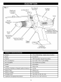
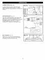
Im]::(..__o]
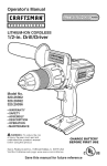
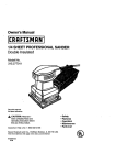
Fig.
1
Depth rod
of Auxiliary
Handle
Locking Knob
_1
Two-Speed
GearBox
Auxiliary
Handle
Vents
Torque
Adjustment
Ring
Direction of
Rotation Selector
FORWARD/CENTEF
LOCK/REVERSE)
Jaws
g
Keyless
Chuck
Hammer Function
Selection
Ring
Trigger
Switch
Integrated
LED Worklight
I ".l:[e] mlU[_ iI-'] "J=[_]I ;I [e?.,_l
i[e] #6"]
Chuck
1/2-in. Ratcheting, single-sleeve
Motor
20 Volt DC
Switch
VSR (Variable Speed Reversible)
No Load Speed
LO 0-350 / HI 0-1,300 (RPM)
No load BPM
LO 0-6300/HI
Clutch
24 Position
Torque
540 in. Ibs.
Hammer Drill/Driver Weight (without battery)
4.2 Ibs.
0-23400
Battery Type
Lithium-Ion
Battery Voltage
20.0 Volt DC
Charger Input
120-Volts, 60 Hz AC only
Optimum Charging Temperature
32°F (0 ° C) -104°F (40°C)
10
keyless
Im]::(.,.__o]
KNOW YOUR HAMMER
I
DRILL/DRIVER
_1
(Fig. 1)
the tool and in this operator's manual as well as a knowledge of the project you are attempting.
_,WAR
N Iof
N G"
safe use
of this product
an understanding
thesafety
information
Before use
thisThe
product,
familiarize
yourselfrequires
with all operating
features of
and
rules. on
ADJUSTABLE TORQUE
The drill has a 24-position clutch. The torque adjustment
amount of torque for your application.
clutch can be turned to select the right
TWO-SPEED
GEAR BOX
The two-speed gear box is designed for drilling or driving at LO or HI speeds. A slide switch is
located on top of your drill for selecting the appropriate speed.
VARIABLE
SPEED
The variable speed trigger switch delivers higher speed with increased
speed with decreased trigger pressure.
trigger pressure and lower
RATCHETING KEYLESS CHUCK
The keyless chuck allows you to hand-tighten or release the drill bit in the chuck jaws. The
ratcheting feature is designed to prevent the chuck from opening during operation.
FORWARD/REVERSE/CENTER
LOCK
The drill has a direction of rotation selector located above the trigger switch for changing the
direction of bit rotation. Setting the trigger switch in the OFF (center lock) position helps reduce
the possibility of accidental starting when not in use.
HAMMER
FUNCTION
The hammer drill/driver
comes with hammer function for heavy location use.
AUXILIARY HANDLE
The drill is equipped with an auxiliary handle for ease of operation
and to prevent loss of control.
LED WORKLIGHT
The LED worklight, located on the front of the drill base, illuminates when the trigger switch is
depressed. This feature provides extra light for increased visibility.
_..-'_-']=hVt
I--]_'d
NOTE= If any parts are broken or missing, DO NOT attempt to plug in the power cord or operate
drill until the broken or missing parts are replaced. Failure to do so could result in possible
serious injury.
NOTE" Do not attempt to modify this drill or create accessories not recommended for use with
this drill. Any such alteration or modification is misuse and could result in a hazardous condition
leading to possible serious injury.
I
always
%,WARNI
remove
NG" the
To prevent
battery accidental
pack from the
starting
drill when
that could
assembling
cause serious
parts. personal injury,
UNPACKING
This product has been shipped completely
assembled.
•
Carefully remove the tool and any accessories
the packing list are included.
•
Inspect the tool carefully to make sure no breakage or damage occurred during shipping.
•
Do not discard the packing material until you have carefully inspected
operated the drill.
•
If any parts are damaged or missing, please refer to the numbers listed on the back page of
operator's manual.
PACKING
from the box. Make sure that all items listed in
and satisfactorily
LIST
Hammer Drill/Driver
Operator's Manual
with Auxiliary Handle, Double-ended
11
Bit, Carry Bag, 2 Lithium-ion
batteries,
I
I
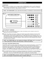
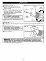
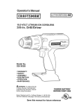
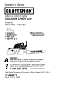
POWER BAR
• This Lithium-Ion battery pack is equipped with a POWER BAR which is used to display the
battery pack's remaining run time. Press the POWER BAR button to display the LED lights.
The LED lights will stay lit for approximately 4 seconds.
NOTE: The POWER BAR can be used when the battery is attached
or removed from tool. I
Fig. 2
(_
0000_
POWER
• • • •
80-100%
Charge
0000
80-79O/o
Charge
OO00
40-59o/o
Charge
0 0 0 •
20-3
O/o
Charge
BAR
_1.
O
O'_,
• ',,',,'-,',
"_
,(_L ,i_'_ ,(_'_,
J
LOW CAPACITY
O
_" Charge
Under 10°/o
Completely
_" discharged
WARNING
•
If one LED on the POWER BAR begins to flash, the battery pack's charge is under 10%
capacity and should be recharged.
•
Unlike other battery pack types, Lithium-Ion battery packs deliver fade-free power for their
entire run time. The tool will not experience a slow, gradual loss of power as you work. To
signal that the battery pack is at the end of its run time and needs to be charged, power to the
tool will drop quickly. The POWER BAR will begin to display four flashing LED lights when it is
completely discharged. When this happens, remove the tool from the workpiece and charge
the battery pack as needed.
NOTE: The POWER BAR may also display four flashing LED lights due to an overload
or high temperature situation (see SmartChip TM Battery protection).
SmartChip
TM
BATTERY PROTECTION
SmartChip TM intuitive circuitry protects the battery pack from extreme temperature, over-discharge
and over-charge. To protect the battery from damage and prolong its life, the battery pack's
SmartChip TM circuitry will turn off the battery pack if it becomes overloaded or if the temperature
becomes too high during use. This may happen in extremely high torque, binding and stalling
situations. This intelligent system will shutdown your battery pack if its operating temperature
exceeds 176°F (80°C) and will begin normal operation when it returns to 32°F (O°C) - 122°F (50°C).
• The POWER BAR will display four flashing LED lights if the SmartChip TM circuitry detects a
momentary overload. You can conveniently reset the battery pack by pressing the POWER
BAR button. Press the POWER BAR button again to display the remaining charge.
I
NOTE: If the POWER BAR continues to flash four LED lights after reset, place the battery I
pack on the charger to evaluate the battery condition (see Fig. 4).
I
12
NOTE: A significantly reduced run time after fully charging the battery pack indicates
that the batteries are near the end of their usable life and must be replaced.
COLD WEATHER OPERATION
• This Lithium-Ion battery pack will provide optimal performance in temperatures between 32°F
(O°C) and 104°F (40°C), When the battery pack is very cold, it may "pulse" for the first minute
of use to warm itself up, Put the battery pack on a tool and use the tool in a light application,
After about a minute, the battery pack will have warmed itself up and will operate normally,
WHEN TO CHARGE THE BATTERY PACK
The Lithium-Ion battery can be charged at any time and will not develop a "memory" when
charged after only a partial discharge, It is not necessary to run down the battery pack charge
before recharging, Remove the battery pack from the tool when convenient for you and your job,
•
Use the POWER BAR to determine when you need to recharge the battery pack.
• You can "top-off"
•
your battery pack's charge before starting a big job or long period of use.
Due to Lithium-Ion's fade-free properties, the only time it is necessary to charge the LithiumIon battery pack is when the pack has reached the end of its charge. To signal the end of
charge, power to the tool will drop quickly. Charge the battery pack as needed.
13
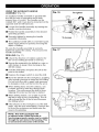
HOW
TOCHARGE
THEBATTERY
PACK
NOTE: This Lithium-Ion
battery pack is shipped
first time, fully charge the battery pack.
A fully discharged battery pack with a
temperature between 32°F (O°C) and 104°F
(40°C) will charge in about 50 minutes.
•
Charge the Lithium-Ion battery pack only
with the correct charger.
•
Connect the charger to a power supply.
partially
charged.
Before
using it the
Fig. 3
• Attach the battery pack to the charger by
aligning the raised ribs of the battery pack
with the slot in the charger. Slide the battery
pack onto the charger (Fig. 3, 3a)
• The charger will communicate with the
battery pack's SmartChip TM circuitry to
evaluate the condition of the battery pack.
• The POWER BAR LED lights will cycle from
right to left during charging. This is part of
the normal charging operation.
• After charging is complete, the green LED
on the charger will come on and the POWER
BAR LED lights will go off. The POWER BAR
LED lights will not be displayed when the
POWER BAR button is pressed while the
battery pack is on the charger.
Charger# 320.25709
Fig. 3a
• The battery pack will fully charge, but will not
overcharge, if left on the charger.
Charger# 320.257091
I
I
NOTE: Forrated
inverters
your atconvenience,
300 watts or the
higher.
charger can operate with most generators
14
and
I
I
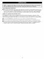
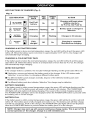
LED FUNCTIONS
OF CHARGER
(Fig. 4)
Fig. 4
BATTERY
PACK
LED INDICATOR
RED
LED
GREEN
LED
ACTION
On
Off
Charging will begin when
battery returns to
32°F (0°C)-104°F (40°C)
Defective
Flashing
Off
Battery pack or charger
defective
Charging
Off
Flashing
Charges in 50 minutes
Fully
charged
Off
On
Charging is complete
Maintenance charging
Hot/Cold
(SEE
HI/LO
MANUAL)
TEMP.
battery
BATTERY
DEFECTIVE
_
CHARGING
BATTERY
_
FULL
BATTERY
CHARGING
is
A HOTBATTERYPACK
If the battery pack is above normal temperature range, the red LED will be lit and the green LED
will be off, When the battery pack cools down to approximately 104°F (40°C), the charger will
automatically begin charging,
CHARGING
A COLDBATTERYPACK
If the battery pack is below the normal temperature range, the red LED will be lit and the green
LED will be off, When the battery warms to a temperature of more than 32°F (O°C), the charger
will automatically begin charging,
DEFECTIVE
BATTERY
If the charger detects a problem, the red LED will begin flashing and the green LED will be off.
•
If defective, remove and reinsert the battery pack in the charger. If the LED status reads
"defective" a second time, try charging a different battery pack.
•
If a different battery pack charges normally, dispose of the defective battery pack (see
Maintenance section).
•
If a different battery pack also indicates "defective," the charger may be defective.
BATTERY CHARGING
If the battery pack is within normal temperature range, the green LED will begin flashing and the
red LED will be off, The battery pack will reach a full charge in 50 minutes, The POWER BAR
LED lights will cycle right to left during charging, This is part of the normal charging operation,
The POWER BAR LED lights will not be displayed when the POWER BAR button is pressed while
the battery pack is on the charger,
BATTERY FULL
If the battery pack is within normal temperature range, the green LED will be lit and the red LED
will be off, The battery pack is fully charged and ready to use, The battery pack will fully charge,
but will not overcharge, if left on the charger, The POWER BAR LED lights will not be displayed
when the POWER BAR button is pressed while the battery pack is on the charger,
NOTE: Charger may warm up with several continuous charge cycles. This is part of the
normal operation of the charger. Charge in a well ventilated area.
15
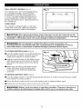
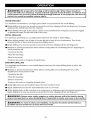
WALL-MOUNT
CAPABLE
(Fig. 5)
Fig. 5
The charger has a key-hole hanging feature
for convenient storage. Screws should
be installed so that the center distance is
4-1/8-in. Use appropriate wall fasteners to
accommodate the combined weight of the
charger and battery pack. (approximately 3.5
Ibs. combined)
©
_
4-1/8-in.
d_
©
CORD WRAP
0
The charger is equipped with a cord wrap
on the rear of the unit. Utilize this feature to
minimize workspace clutter and hazards.
0
_,CAUTION:
When placing the battery pack in the tool, be sure the raised rib on the
battery pack aligns with the bottom of the drill and latches into place properly. Improper
installation of the battery pack can cause damage to internal components.
_,WARNING"
Do not attempt to modify this drill or create accessories not
recommended for use with this drill. Any such alteration or modification is misuse
and could result in a hazardous condition leading to possible serious injury.
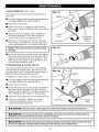
TO ATTACH BATTERY PACK (Fig. 6)
•
Fig. 6
Lock the trigger switch on the drill by placing
the direction of rotation (forward/reverse/
center lock) selector in center position
• Align the raised portion on the battery pack
with the grooves on the bottom of the drill,
then attach the battery pack to the drill as
shown
•
Make sure the latch on the battery pack
snaps into place and the battery pack
is secured to the drill before beginning
operation.
TO DETACH BATTERY
PACK (Fig. 6)
•
Lock the trigger switch on the drill by placing the direction
lock) selector in center position
of rotation (forward/reverse/center
•
Press the latch located on the front of the battery pack to release battery pack.
•
Pull forward on the battery pack to remove from the drill.
_WARNING:
Battery tools are always in operating condition. Therefore, direction
rotation selector should always be locked when not in use or carrying at your side.
16
of
TRIGGER
SWITCH
(Fig.7)
ToturnthedrillON,depress
theswitch
trigger.
ToturnitOFF,
release
thetrigger.
VARIABLE
SPEED
(Fig,7)
Thevariable
speed
trigger
switch
delivers
higher
speed
withincreased
trigger
pressure
andlower
speed
withdecreased
trigger
pressure.
DIRECTION
OFROTATION
SELECTOR
(FORWARD/REVERSE/CENTER
LOCK)
(Fig.7)
Thedirection
ofbitrotation
isreversible
and
iscontrolled
byaselector
located
above
the
trigger
switch.
Withthedrillheldinnormal
operating
position:
• Position
thedirection
ofrotation
selector
to
theleftofthetoolfordrilling.
• Position
thedirection
ofrotation
selector
to
theright
ofthetoolforreverse.
• Setting
theswitch
intheOFF(center
lock)
position
helps
reduce
thepossibility
of
accidental
starting
when
notinuse.
Fig. 7
Direction
of rotation
selector
_,CAUTION:
To prevent gear damage, always allow the chuck to come to complete
stop before changing the direction of rotation.
NOTE: The drill will not run unless the direction
the left or right.
ELECTRIC
of rotation selector
is engaged
fully to
BRAKE
To stop the drill, release the trigger switch and allow the chuck to come to a complete stop. The
electric brake quickly stops the chuck from rotating. This feature engages automatically when you
release the trigger switch.
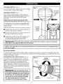
RATCHETING
KEYLESS
CHUCK
(Fig. 8)
Fig. 8
The drill has a ratcheting keyless chuck to
tighten or release drill bits in the chuck jaws.
The arrows on the chuck indicate which
direction to rotate the chuck body in order to
GRIP (tighten) or OPEN (release) the chuck
jaws on the drill bit. The ratcheting feature is
designed to prevent the chuck from opening
during operation.
_,WARNING:
OPEN
(release)
Chuck
jaws
Do not hold the chuck
body with one hand and use the power
of the drill to tighten the chuck jaws on
the drill bit. The chuck body could slip
in your hand, or your hand could slip
and come in contact with the rotating
bit. This could cause an accident
resulting in serious personal injury.
GRIP
(tighten)
17
Chuck
Ratcheting
keyless
TWO-SPEED
GEAR BOX (Fig. 9)
Fig. 9
The drill has a two-speed gear box designed
for drilling or driving at LO or HI speeds. A
slide switch is located on the top of the drill to
select either LO or HI speed. When using drill
in the LO speed range, speed will decrease
and the drill will have more power and torque.
When using drill in the HI speed range, speed
will increase and the drill will have less power
and torque. Use LO speed for high power and
torque applications and HI speed for fast drilling
or driving applications.
Two-speed
gearbox
switch
HI
LO
NOTE: Avoid running the drill at LO
speed for extended periods of time.
Running at LO speed under constant
usage may cause the drill to become
overheated. If this occurs, cool the drill
by running it without a load at HI speed.
I
_,CAUTION:
Never change gears while the tool is running.
could result in serious damage to the drill.
ADJUSTABLE
TORQUE
CLUTCH
Failure to obey this caution
I
(Fig. 10)
When using the hammer drill/driver for different driving applications, it is necessary to increase
or decrease the torque in order to help prevent the possibility of damaging screw heads, threads,
workpiece, etc. In general, torque intensity should correspond to the screw diameter. If the torque
is too high or the screws too small, the screws may be damaged or broken.
The torque is adjusted by rotating the torque
adjustment ring.
Fig.
10
To decrease
torque
The torque is greater when the torque
adjustment ring is set on a higher setting. The
torque is less when the torque adjustment is set
on a lower setting.
The proper setting depends on the type of
material and the size of screw you are using.
Select the option that best matches the type of
bit, fastener and material you will be using.
•
Choose the correct speed: LO or HI.
•
Choose the correct torque setting.
Torque
adjustment
ring
To increase
torque
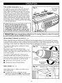
DRILL MODE (Fig. 11)
Fig.
Select drill mode for drilling and other heavy
duty applications.
11
Drill ico_
• To select drill mode, rotate the torque
adjustment ring until the,_,l icon aligns with
the torque indicator and clicks into position.
18
i
Hammer
Icon
Torque indicator
HAMMER MODE (Fig. 11a)
Fig, 11a
Hammer
Icon
Torque indicator
To select hammer mode, rotate the torque
adjustment ring until the hammer icon_
is
aligned with the torque indicator, and clicks into
position.
LED WORKLIGHT
(Fig, 12)
Fig.
12
The LED worklight located on the base of the
drill will come on when the trigger switch is
depressed. The LED worklight will turn off when
the trigger switch is released. This provides
additional lighting on the surface of the
workpiece for operation in lower-light areas.
Variable
:h
LED
worklight
BIT STORAGE
(Fig, 13)
Fig.
When not is use, the bit provided with the
drill can be stored on the base of the drill by
snapping it into place in the bit clip.
19
13
INSTALLING
•
BITS (Fig. 14)
Fig.
Lock the trigger switch by placing the
direction of rotation selector in the OFF
(center) position.
Drill bit
• Open or close the chuck jaws to a point
where the opening is slightly larger than the
bit size you intend to use. Also, raise the
front of the drill slightly to keep the bit from
falling out of the chuck jaws.
•
14
Ratcheting
keyless
chuck
Chuck
jaws
OPEN
(release)
Insert a drill bit.
NOTE: Rotate the chuck body in the
direction of the arrow marked GRIP to
close the chuck jaws. Do not use a wrench
to tighten or loosen the chuck jaws.
Chuck
body
GRIP
(tighten)
• Tighten the chuck jaws securely on the bit.
REMOVING
•
BITS (Fig. 14)
Lock the trigger switch by placing the direction
of rotation selector in the OFF (center) position.
• Open the chuck jaws.
NOTE: Rotate the chuck body in the
direction of the arrow marked OPEN to
open the chuck jaws. Do not use a wrench
to tighten or loosen the chuck jaws.
•
Fig,
15
WRONG!
Remove the drill bit.
WRONG!
_WARNING:
Make sure
insert the drill bit into the
This could cause the drill
personal injury or damage
to insert the drill bit straight into the chuck jaws. Do not
chuck jaws at an angle then tighten, as shown in figure 15.
bit to be thrown from the drill, resulting in possible serious
to the chuck.
20
I
USING THE AUXILIARY
ASSEMBLY
HANDLE
(Fig. 16)
I Fig.
To tighten
16
An auxiliary handle assembly is packed with
the drill for ease of operation and to help
prevent loss of control. The handle can be
rotated 360 ° and it can also be mounted on the
opposite side for left hand use.
•
Loosen the handle assembly
handle counterclockwise.
•
Rotate the handle assembly
operating position.
•
Securely tighten by turning the handle
assembly clockwise.
360 °
by turning the
to the desired
To loosen
• The auxiliary handle with 2 convenient quick
depth stops allows for quickly choosing the
depth of drilling.
Be sure the handle assembly is securely
tightened against the clamp. This secures the
handle assembly.
DRILLING
Fig.
(Fig. 17)
•
Check the direction of rotation selector for
the correct setting (forward or reverse).
•
Secure the material to be drilled in a vise or
with clamps to keep it from turning as the
drill bit rotates.
•
Hold the drill firmly and place the bit at the
point to be drilled.
•
Depress the trigger switch to start the drill.
•
Move the drill bit into the workpiece, applying
only enough pressure to keep the bit cutting.
Do not force the drill or apply side pressure
to elongate a hole. Let the tool do the work.
• When drilling hard, smooth surfaces, use
a center punch to mark the desired hole
location. This will prevent the drill bit from
slipping off-center as the hole is started.
• When drilling metals, use a light oil on the
drill bit to keep it from overheating. The oil
will prolong the life of the bit and increase
the drilling action.
•
If the bit jams in the workpiece or if the drill
stalls, stop the tool immediately. Remove the
bit from the workpiece and determine the
reason for jamming.
NOTE: This drill is equipped with
an electric brake. When the brake is
functioning properly, sparks may be visible
through the vent slots in the housing. This
is normal and is the action of the brake.
21
17
_WARNING:
Be prepared
for binding at bit breakthrough. When these situations
occur, the drill has a tendency to grab and kick opposite to the direction of rotation and
could cause loss of control when breaking through material. If not prepared, this loss of
control can result in possible serious injury.
WOOD DRILLING
For maximum performance,
•
use high speed steel or brad point bits for wood drilling.
Begin drilling at a very low speed to prevent the bit from slipping off the starting point. Increase
speed as the drill bit bites into the material.
• When drilling "through" holes, place a block of wood behind the workpiece
or splintered edges on the back side of the hole.
to prevent ragged
METAL DRILLING
For maximum performance,
use high speed steel bits for metal or steel drilling.
• When drilling metals, use a light oil on the drill bit to keep it from overheating.
prolong the life of the bit and increase the drilling action.
The oil will
•
Begin drilling at a very low speed to prevent the bit from slipping off the starting point.
•
Maintain a speed and pressure which allows cutting without overheating
much pressure will:
- Overheat
the bit. Applying too
the drill.
- Wear the bearings.
- Bend or burn bits.
- Produce off-center
MASONRY
or irregular-shaped
For maximum performance,
concrete, etc.
•
holes.
DRILLING
use carbide-tipped
masonry bits when drilling holes in brick, tile,
Maintain a speed and pressure which allows cutting without overheating
Applying too much pressure will:
- Overheat
the bit or drill.
the drill.
- Wear the bearings.
- Bend or burn bits.
- Produce off-center
or irregular-shaped
holes.
• Apply light pressure and medium speed for best results in brick.
• Apply additional
pressure for hard materials such as concrete.
• When drilling holes in tile, practice on a scrap piece to determine the best speed and pressure.
Begin drilling at a very low speed to prevent the bit from slipping off the starting point.
I
I
power
,WARNING:
tool operation
Alwaysorwear
whensafety
blowing
goggles
dust. or
If operation
safety glasses
is dusty,
withalso
sidewear
shields
a dust
during
mask. I
I
qualified
WARNING:
serviceTotechnician
ensure safety
at Sears
and Service
reliability,Center.
all repairs should be performed
22
by a
II
GENERAL
MAINTENANCE
Avoid using solvents when cleaning plastic parts. Most plastics are susceptible to damage from
various types of commercial solvents and may be damaged by their use. Use clean cloths to
remove dirt, dust, oil, grease, etc.
_WARNING:
Do not at any time let brake fluids, gasoline, petroleum-based
products,
penetrating oils, etc., come in contact with plastic parts. Chemicals can damage,
weaken or destroy plastic which may result in serious personal injury.
_WARNING:
To avoid serious personal injury, always remove the battery pack from the
tool and unplug the charger when cleaning or performing any maintenance.
BATTERIES
The battery pack is equipped with Lithium-Ion rechargeable
each charge will depend on the type of work performed.
batteries. The duration of use from
The batteries in this tool have been designed to provide maximum trouble-free life. Like all
batteries, they will eventually wear out. Do not disassemble the battery pack or attempt to replace
the batteries. Handling of the batteries, especially when wearing rings and jewelry, could result in
a serious burn.
To obtain the longest possible
•
battery life, read and understand
the operators
It is good practice to unplug the charger and remove the Lithium-Ion
use.
For Lithium-Ion
manual.
battery pack when not in
battery pack storage longer than 30 days:
•
Store the Lithium-Ion
moisture.
battery pack where the temperature
•
Store Lithium-Ion
•
Every six months of storage, fully charge the Lithium-Ion
battery pack.
•
Exterior may be cleaned with a cloth or soft non-metallic
brush.
battery packs in a 30%-50%
BATTERY PACK REMOVAL
AND PREPARATION
is below 80°F (26°C) and free of
charged condition.
FOR RECYCLING
To preserve natural resources, please recycle or dispose of batteries properly.
This product contains lithium-ion batteries. Local, state or federal laws may
prohibit disposal of lithium-ion batteries in ordinary trash. Consult your local
waste authority for information regarding available recycling and/or disposal
options.
_WARNING:
Upon removal, cover the battery pack's terminals with heavy-duty
adhesive tape. Do not attempt to destroy or disassemble the battery pack or remove
any of its components. Lithium-Ion batteries must be recycled or disposed of properly.
Also, never touch the terminals with metal objects and/or body parts as a short circuit
may result. Keep away from children. Failure to comply with these warnings could
result in fire and/or serious injury.
23
CHUCK
REMOVAL
(Fig.18-20)
Fig. 18
Thechuck
canberemoved
andreplace
bya
new
one.
Mallet
• Lock
thetrigger
switch
byplacing
thedirection
ofrotation
selector
incenter
position.
• Open
thechuck
jaws.
• Insert
a5/16-in.
orlarger
hexkeyintothe
chuck
ofthedrillandtighten
thechuck
jaws
securely.
• Tapthehexkeysharply
withamallet
ina
Chuck
clockwise
direction.
Thiswillloosen
the
Jaws
screw
inthechuck
foreasyremoval.
• Open
thechuck
jawsandremove
thehex
Hex key
key.
Using
ascrewdriver,
remove
thechuck
screw
byturning
itinaclockwise
direction.
I
I
threads.
NOTE: The chuck screw has left handed
•
Insert the hex key into the chuck and tighten
the chuck jaws securely. Tap sharply with a
mallet in a counterclockwise
direction. This
Fig.
Ratcheting
keyless
chuck
19
I
I
Screwdriver
will loosen the chuck on the spindle. It can
now be unscrewed by hand.
TO RETIGHTEN
A LOOSE CHUCK
The chuck may become loose on the spindle
and develop a wobble. Also, the chuck screw
may become loose, causing the chuck jaws to
bind and prevent them from closing.
Fig. 20
To tighten a loose chuck or chuck screw:
•
Lock the trigger switch by placing the direction
of rotation selector in center position.
• Open the chuck jaws.
•
Insert the hex key into the chuck and tighten
the chuck jaws securely. Tap the hex key
sharply with a mallet in a clockwise direction.
This will tighten the chuck on the spindle.
• Open the chuck jaws and remove the hex key.
•
I
Using a screwdriver, tighten the chuck
screw by turning the chuck screw in a
counterclockwise
direction.
_WARNING:
Hex key
_
_
Chuck
Jaws
Always wear safety glasses with side shields during maintenance.
_,WARNING:
To ensure safety and reliability, all repairs should be performed
qualified service technician at Sears Service Center.
by a
_kWARNING:
To avoid serious personal injury, always remove the battery pack from the
tool and unplug the charger when cleaning or performing any maintenance.
24
I
J
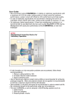
©
\
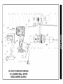
20.0 VOLT LITHIUM-ION
1/2-in. HAMMER
MODEL
CORDLESS
DRILL / DRIVER
NUMBER
320.29004
i#,__I.-tl
_...][_,..._g
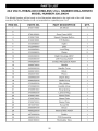
20.0 VOLT LITHIUM-ION CORDLESS 1/2-in. HAMMER
MODEL NUMBER 320.29004
DRILL/DRIVER
The Model Number will be found on the Nameplate attached to the right side of the drill, Always
mention the Model Number in all correspondence
regarding your tool,
ITEM
NO.
1
PARTS
NO.
PART DESCRIPTION
QTY.
2730114000
DC Motor
1
3
2790125000
Gear Case ASSY
1
4
3122817000
Speed Change Button
1
5
3122818000
F/R Button
1
6
3122938000
Splint
1
7
3122946000
plate
1
8
3123605000
Lock Ring
1
9
3123608000
Clamp
2
10
3320359000
Right Housing ASSY
1
11
3320360000
Left Housing ASSY
1
12
3400260000
Contact Receptacle ASSY
1
13
3400274000
Handle
1
14
3420500000
Handle Cover
1
15
3420613000
Block
1
16
3520351000
Pin ion
1
17
3550953000
Depth Stop
1
18
3660252000
Hadle Hoop
1
2
19
3700405000
Bits Holder
1
20
3700960000
Handle Hoop
1
21
3700961000
Stop Spring
1
22
3700963000
Lantern Ring
1
23
3700971000
Name Plate
1
24
3700972000
Name Plate
1
25
3700973000
Name Plate
1
26
3810357000
Screw Bit
1
27
3860084000
Chuck
1
28
4860225000
Internal Wire ASSY
1
29
4870303000
Switch
1
30
4890301000
31
4920180000
PCB Assembly
Shrinkable
26
Tube
1
1
i#,__I
=tl_...][_,..._g
20.0 VOLT LITHIUM-ION
CORDLESS 1/2-in. HAMMER
MODEL NUMBER 320.29004
DRILL/DRIVER
The Model Number will be found on the Nameplate attached to the right side of the drill, Always
mention the Model Number in all correspondence
regarding your tool,
ITEM
NO.
PARTS
NO.
PART
DESCRIPTION
QTY.
32
5610013000
Tapping Screw
8
33
5610032000
Tapping Screw
4
34
5620049000
Screw
2
35
5620325000
Screw (L.H.)
1
36
5630003000
Hexagon Nut
1
37
5640047000
Wing Bolt
1
38
5640175000
Lock Bolt
1
39
5650015000
Spring Washer
2
SEE BACK
PAGE
FOR PARTS
ORDERING
INSTRUCTIONS
27
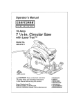
Your Home
For expert troubleshooting and home solutions advice:
manage
home
www.managemyhorne.corn
For repair - in your home - of all major brand appliances,
lawn and garden equipment, or heating and cooling systems,
no matter who made it, no matter who sold it !
For the replacement parts, accessories and
owner's manuals that you need to do-it-yourself.
For Sears professional installation of home appliances
and items like garage door openers and water heaters.
1-800-4-MY-HOME
(1-800-469-4663)
www.sears.com
®
Call anytime, day or night
(U.S.A. and Canada)
www.sears.ca
Our Home
For repair of carry-in items like vacuums, lawn equipment,
and electronics, call anytime for the location of the nearest
Sears Parts & Repair Service Center
1-800-488-1222 (U.S.A.)
www,sears.com
1-800-469-4663 (Canada)
www,sears,ca
To purchase a protection
on agreement on a product
proc
serviced by Sears:
1-800-827-6655 (U.S.A.)
Para pedir serviciode reparaci6n
,=paraci6n
a domicilio,y para ordenar
tar piezas:
1-888-SU-HOGAR®
,R®
1-800-5
1-800-361-6665
(Canada)
Au Canada
Canad_ pour service en franr_ais:
1-800-LE-FOYERMc
1-E
11-8oo- .6 37)
www.sears.ca
Sears
© Sears Brands,LLC
® Registered Trademark / TMTrademark / SMService Mark of Sears Brands, LLC
_ Marca Registrada / TMMarca de F&brica / sM Marca de Servicio de Sears Brands, LLC
MCMarque de commerce / MDMarque depos6e de Sears Brands, LLC