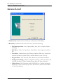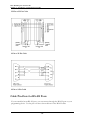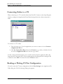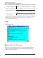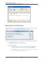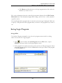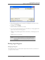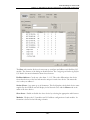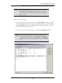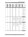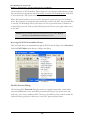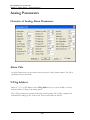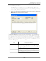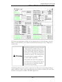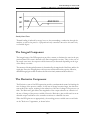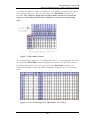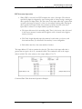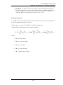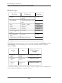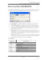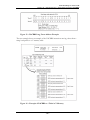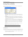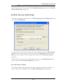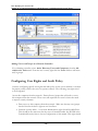
1
USER GUIDE
PLC WorkShop for Siemens 505
Version 4.80
© 2014 FasTrak SoftWorks, Inc.
www.fast-soft.com
262.238.8088
Throughout this document, PLC WorkShop for Siemens 505 will be referred to as PLC
WorkShop, 505 WorkShop, or WorkShop. PLC WorkShop is atrademark of FasTrak
SoftWorks, Inc. 505 is atrademark of Siemens.Windows is aregistered trademark of
Microsoft Corporation. Other product names mentioned herein are used for identification purposes only and may be trademarks of their respective companies.
LICENSE TERMS AND CONDITIONS
FasTrak SoftWorks, Inc.
Licensor is the owner of all rights, including the copyright, in and to that certain set of executable computer programs identified
in the Registration Form, including design and structure thereof (the "Software"), together with all manuals and other written or
printed technical material provided with the Software to explain its operation and to aid in its use (the "Documentation").
Licensee wishes to have the right to use the Software, and Licensor is willing to grant such a right to Licensee on the terms and
conditions set forth herein.
1. GRANT OF LICENSE. In consideration of Licensee's payment of the license fee referred to below and Licensee's agreement
to abide by the terms and conditions stated herein, FasTrak SoftWorks, Inc. (referred to as "Licensor") grants Licensee a
nonexclusive right to use and display one (1) copy of the Software with respect to one microcomputer at a time for so long as
Licensee complies with the terms hereof. Licensor retains the right to terminate this Agreement and Licensee's rights at any time,
by written notice to Licensee, in the event Licensee violates any of the provisions hereof.
Licensor reserves all rights in and to the Software and Documentation not expressly granted to Licensee herein. Licensee agrees
to pay Licensor the license fee specified by Licensor as of the date hereof, payable in full upon deliver of a copy of the
Software and Documentation to Licensee. Licensee acknowledges that the license fee payable hereunder is consideration solely
for the right to use the Software, and payment thereof will not entitle Licensee to support, assistance, training, maintenance or
other services, or the enhancements or modifications to the Software which may subsequently be developed by Licensor, except
as otherwise expressly provided in this Agreement.
2. LICENSEE'S AGREEMENTS. Licensee agrees to comply with the terms and conditions set forth in this Agreement,
specifically including but not limited to the following:
a. Licensee will take all reasonable steps to protect the Software from theft or use contrary to the terms of this
Agreement.
b. Licensee agrees to pay Licensor additional license fees as specified by Licensor if and to the extent Licensee intends
to use or does use the Software in any way beyond the scope of this Agreement.
c. Licensee agrees not to modify the Software and not to disassemble, decompile, or otherwise reverse engineer of the
Software.
d. Licensee agrees to either destroy or return the original and all existing copies of the Software to Licensor within
five (5) days after receiving notice of Licensor's termination of this Agreement.
e. Licensee agrees not to disclose the Software or Documentation or any part thereof or any information relating
thereto to any other party, it being understood that the same contains and/or represents confidential information
which is proprietary to Licensor.
3. OWNERSHIP OF SOFTWARE. Licensee shall be deemed to own only the magnetic or other physical media on which the
copy of the Software provided to Licensee is originally or subsequently recorded or fixed, as well as any boards, key-locks, or
cables provided for use with the Software, but an express condition of this Agreement is that Licensor shall at all times retain
ownership of the Software recorded on the original diskette copy and all subsequent copies of the Software, regardless of the
form or media in or on which the original or other copies may initially or subsequently exist. This Agreement does not
constitute a sale of any copy of the Software to Licensee.
4. POSSESSION AND COPYING. Licensee agrees that the Software will only be displayed or read into or used on one (1)
computer at a time, at the location designated for notices to Licensee under paragraph 13, below. Licensee may change the
computer on which Licensee uses the Software to another computer at such location. Licensee agrees not to make copies of the
Software other than for its own use, all of which copies shall be kept in the possession or direct control of Licensee. Licensee
agrees to place a label on the outside of all copies showing the program name, version number, if applicable, and Licensor's
copyright and trademark notices in the same form as they appear on the original licensed copy
5. TRANSFER OR REPRODUCTION. Licensee is not licensed to copy, rent, lease, transfer, network, reproduce, display or
otherwise distribute the Software except as specifically provided in this Agreement. Licensee understands that unauthorized
reproduction of copies of the Software and/or unauthorized transfer of any copy of the Software is a violation of law and will
subject Licensee to suit for damages, injunctive relief and attorney's fees. Licensee further understands that it is responsible for
the acts of its agents and employees. Licensee may not transfer any copy of the Software to another person or entity, on either a
permanent or temporary basis, unless Licensee obtains the prior written approval of Licensor which will ordinarily be subject to
payment of Licensor's then current license transfer fee. Such approval will not unreasonably be withheld if Licensee advises
Licensor in writing of the name and address of the proposed transferee, such transferee is suitable in Licensor's sole judgement,
and such transferee agrees in writing to be bound by the terms and conditions of this Agreement. If the transfer is approved,
Licensee must deliver all copies of the Software, including the original copy to the transferee.
6. ENHANCEMENTS AND UPDATES. Licensor may from time to time release updates of the Software incorporating changes
intended to improve the operation and/or reliability of the Software. Such updates will be provided to Licensee at no charge
(except shipping charges and media costs) for a period of twelve (12) months from the date hereof, and Licensee agrees to install
all updates designated by Licensor as mandatory. Licensor may also offer enhanced versions of the Software from time to time
incorporating changes intended to provide new or enhanced features and/or capabilities, at such license fees as Licensor may
from time to time establish.
7. LIMITED WARRANTY AND DISCLAIMER OF LIABILITY. LICENSOR HAS NO CONTROL OVER THE
CONDITIONS UNDER WHICH LICENSEE USES THE SOFTWARE. THEREFORE, LICENSOR CANNOT AND DOES
NOT WARRANT THE PERFORMANCE OR RESULTS THAT MAY BE OBTAINED BY ITS USE. HOWEVER,
LICENSOR PROVIDES THE FOLLOWING LIMITED WARRANTY:
Licensor warrants, for a period of twelve (12) months only, that the Software shall be free from significant programming errors.
Licensor further warrants that it has full power and authority to grant the rights granted by this Agreement with respect to the
Software and that the use by Licensee of the Software and Documentation will not infringe the rights of others. In the event
Licensee believes that it has discovered one or more significant programming errors, Licensee shall immediately notify Licensor
of such fact in writing. If such notice is received by Licensor within twelve (12) months from the date hereof, Licensor shall,
within a reasonable time, subject to the demands of Licensor's other customers and subject to delays beyond Licensor's control
(including but not limited to labor trouble, illness, delays in shipment of materials, and bad weather), at Licensor's expense,
correct the programming errors. In the event Licensor is unable to correct the programming error within a reasonable time,
Licensee may elect to terminate this Agreement and receive a refund of the licensee fee paid hereunder. For purposes hereof, a
programming error is "significant" only if, as a result thereof, the software does not substantially perform the functions
described in the Documentation. Licensor does not warrant that the operation of the Software will be uninterrupted or error
free. EXCEPT FOR THE ABOVE EXPRESS WARRANTY, LICENSOR MAKES AND LICENSEE RECEIVES NO
WARRANTIES, EXPRESS, IMPLIED, STATUTORY OR OTHERWISE, AND LICENSOR SPECIFICALLY DISCLAIMS ANY
IMPLIED WARRANTY OF MERCHANTABILITY OR FITNESS FOR A PARTICULAR PURPOSE.
THE REMEDY PROVIDED HEREIN IS EXCLUSIVE. UNDER NO CIRCUMSTANCES WILL LICENSOR BE
RESPONSIBLE FOR DIRECT, INDIRECT, INCIDENTAL, CONSEQUENTIAL OR OTHER DAMAGES OR LOST
PROFITS. LICENSEE ACKNOWLEDGES THAT THE LICENSE FEE HEREUNDER IS NOT ADEQUATE FOR
LICENSOR TO ASSUME OBLIGATIONS TO LICENSEE GREATER THAN THE EXPRESS REMEDY PROVIDED
ABOVE.
8. GOVERNING LAW. The validity and performance of this Agreement shall be governed by Wisconsin law, except as to
copyright and trademark matters which are governed by United States laws and international treaties. This Agreement is deemed
entered into in Wisconsin. All lawsuits arising out of this Agreement shall be brought in a court of general jurisdiction in
Milwaukee, Wisconsin. Licensor shall be entitled to recover its costs and expenses (including attorney's fees) incurred in
enforcing its rights under this Agreement.
9. WAIVER. The failure of Licensor to enforce any of the provisions hereof shall not be construed to be a waiver of the right to
enforce such provisions at a later time or to enforce any of the other provisions hereof.
10. EFFECT OF TERMINATION. The expiration or termination of this Agreement shall not affect the obligations of Licensee
which by their character are of continuing nature.
11. INTEGRATION. This Agreement sets forth the entire understanding and agreement of the parties shall be bound by any
conditions, definitions, warranties or representations with respect to any of the terms or conditions hereof other than as
expressly provided in this Agreement. This Agreement may only be modified by a writing signed by the party to be charged.
12. BINDING EFFECT. This Agreement shall be binding upon and shall inure to the benefit of the parties hereto and their
respective successors and assigns, subject to the limitations on the transfer of Licensee's rights to the Software provided in
paragraph 5, above.
13. NOTICES. All notices shall be in writing and shall be hand delivered or sent by U.S. mail, first class, postage prepaid, if to
Licensor at its address first above written, and to Licensee at the address indicated in the Registration Form. A party may change
its address for notices at any time by notice to the other party in the manner provided herein, but each party may have only one
address for notices at a time.
14. REGISTRATION FORM. The Registration Form is a part of this Agreement and is incorporated herein by reference. This
Agreement will not take effect, and Licensee will have no rights whatsoever with respect of the Software, unless and until the
Registration Form is duly executed and returned to the Licensor and is accepted by Licensor.
Table of Contents
Chapter 1 – Welcome
Introduction
Using This Manual
What is PLC WorkShop?
27
29
29
31
Features and Benefits
31
Technical Specifications
32
Customer Support
34
Updating Software License Key
35
To obtain the Key Update Code by email:
35
To obtain the Key Update Code by telephone:
36
System Requirements
37
Hardware Requirements
37
Compatible PLCs
38
Chapter 2 – Installation
39
Installing the Software
41
Access Level
42
FasTrak-KEY
44
Attaching the FasTrak-KEY?
44
Troubleshooting the FasTrak-KEY
45
Communications Cable
49
Connect the Communications Cable
49
Cable Pin-Outs for RS-232-C Ports
49
PLC WorkShop for Siemens 505
Table of Contents
Cable Pin-Outs for RS-422 Ports
50
Ethernet Connection
51
Chapter 3 – PLC WorkShop Basics
53
Software Features
55
Starting PLC WorkShop
56
Main Window
57
Main Window
57
Window Description
57
Instruction Bars
58
Menu Bar
59
Multiple Program Windows
59
Status Line
60
Title Bar
60
Main Toolbar
61
Logic Programs
64
Working With Logic Programs
64
Creating a New Logic Program
64
Fast PLC Connection - Connecting to a PLC
65
Open an Existing Logic Program Offline or Online
65
Loading Parts of an Existing Logic Program Online
68
Transfer Offline Program to Online
71
Connecting Online to a 575
72
Reading or Writing 575 Port Configuration
72
Importing Documentation
74
- 6 -
PLC WorkShop for Siemens 505
Table of Contents
Exporting Documentation
75
Address Documentation Text File Format
77
Header Documentation Text File Format
79
Register Value Text File Format
80
Ramp/Soak Text File Format
81
Retrieving Version Information
82
Saving Logic Programs
83
Printing Logic Programs
87
Editing
103
Editing Features
103
Cut
104
Copy
105
Paste
105
Paste With Rewire
106
Undo
107
Clear
108
Delete
109
Insert
111
Merge Memory
112
WorkShop and FTVersionTrak
114
Using WorkShop with FTVersionTrak
114
Getting Started with FTVersionTrak
114
Using FTVersionTrak in WorkShop
115
Opening WorkShop Files
130
- 7 -
PLC WorkShop for Siemens 505
Table of Contents
Saving WorkShop Files
133
Closing WorkShop Files
134
Operation Modes in FTVersionTrak
136
FAQs about FTVersionTrak
137
Tips and Strategies for Team Programming
139
Chapter 4 – WorkShop Setup
141
Introduction
143
Program Setup
144
Application Setup
148
Communication
150
Setting Up Communications
150
Serial or Modem Communication
150
H1 Communications
152
TIWAY
153
TCP/IP
155
Setting Up and Using PROFIBUS–FMS
160
File Associated Communications
163
Fast PLC Setup
164
Printer
166
Printer Setup
166
Page Setup
166
Chapter 5 – PLC Memory & I/O Configuration
169
Memory and I/O Configuration Overview
171
- 8 -
PLC WorkShop for Siemens 505
Table of Contents
PLC Type Setup (Offline)
172
PLC Type Setup (Offline)
172
Changing PLC Types
174
PLC Memory Configuration
174
175
Controller Memory Types
177
Ladder Memory
177
Image Register Memory
177
Control Relay Memory
177
Special Memory
177
Temporary Memory
177
Variable Memory
178
Constant Memory
178
Status Word Memory
178
Timer/Counter Memory
178
Table Move Memory
180
One Shot Memory
180
Shift Register Memory
181
Drum Memory
182
PGTS Discrete Parameter Area
184
PGTS Word Parameter Area
184
User External Subroutine Memory
185
Global Memory: 575 Only
185
VME Memory: 575 Only
185
- 9 -
PLC WorkShop for Siemens 505
Table of Contents
I/O Configuration
186
Controller Functionality in Configuration
186
I/O Configuration Guidelines
186
Accessing I/O Configuration
186
I/O Configuring Procedure
187
Clearing a Base I/O Configuration
189
Profibus-DP Configuration
190
Using the Profibus-DP Configurator
190
Profibus Configuration
191
Using the Profibus Configurator
205
Find Configured I/O
241
Chapter 6 – Programming
243
Online Versus Offline Programming
245
Using the Ladder Editor
246
Programming Ladder
247
Programming Ladder
247
Insert a New Network
247
Insert a New Row
248
Ladder Instructions
249
SF Program and Subroutine Editor
257
Using the SF Program and Subroutine Editor
257
Special Functions Dialog Box
260
Insert a New Row
263
- 10 -
PLC WorkShop for Siemens 505
Table of Contents
Entering Special Function Program Instructions
263
Password-Protected Subroutines
264
Importing and Exporting Special Function Programs and Subroutines
266
Editing Logic
268
Cut
268
Copy
268
Paste
268
Paste With Rewire
269
Clear
270
Delete
270
Insert
271
Right Mouse Button Shortcut Menus
271
Validate and Enter
272
273
Finding Logic
Finding Logic
273
Find Next
275
Find Documentation
275
Search and Replace Address
278
Search and Replace Address
278
Search and Replace Table
279
Data Window
285
Using the Data Window
285
Data Fill
287
- 11 -
PLC WorkShop for Siemens 505
Table of Contents
Customizing the Display
289
Data Format
289
Forcing an Element
291
Show Forces
292
Clear a Forced Element
292
Complete Cross Reference
294
Ladder Network Cross Reference
296
Address Used
297
Displaying Addresses Used
297
Creating an Address Used Listing
297
Address Trace
299
Tracing an Address
299
Invoking Address Trace
299
Unique Address
300
Compare
301
Displaying Processor Faults
304
CTI 2500 Error Codes
305
Startup Errors
305
Fatal Error Codes
305
CTI 2500 User Switch Settings
309
SW1 – Battery Switch
309
SW2: SW4 – Serial Port Baud Rate.
309
SW5 – Serial Port Electrical Interface
310
- 12 -
PLC WorkShop for Siemens 505
Table of Contents
SW6 – Program Port Selection
310
SW7: SW11 – Reserved
311
SW12 – Firmware Update
311
Auxiliary PLC Functions and Displays
312
Displaying Processor Status
312
PLC Operations
313
Changing Ladder Mode
314
Changing Loop Mode
315
Run Controller Diagnostics
316
Programming EEPROMS
317
Programming Port Lockout
317
System Part Number
318
Performing Syntax Check
318
Ladder Status (Online)
319
Initiating a Single Scan
320
RBC Part Number
321
Task Codes Per Scan
321
Diagnostics on Base
322
Hot Backup
323
Password
324
Password Operational Modes
325
PLC Password Alias
333
Powering Up/Restarting the Controller
Power Up Restart
339
339
- 13 -
PLC WorkShop for Siemens 505
Table of Contents
Partial Restart
339
Complete Restart
340
Clearing Memory
341
Selecting (575) Application
342
Chapter 7 – Documentation
343
Ladder, Network, and SF Header Editor
345
Ladder Header
345
Network Header
345
SF Header
346
Network Header Editor
347
Documentation Window
350
Using the Documentation Window
350
Customizing the Display
351
Editing and Creating New Address Documentation
351
Cut, Copy, Paste and Deleting Documentation
354
Searching for an Address, Tag, or Description
356
Pop-Up Menus
357
Documenting in Ladder
358
Overview of Documenting in Ladder
358
Assign Tags
358
Assign Addresses
359
Editing Documentation in Ladder Editor
359
Shared Documentation
359
- 14 -
PLC WorkShop for Siemens 505
Table of Contents
Toggling the Display of Documentation Components
Edit Title Page (Print Only)
360
364
Chapter 8 – Analog Alarms
365
Analog Alarm Editor
367
To access the Analog Alarm Editor:
367
To delete an Analog Alarm:
368
Copy and Paste Alarms
369
369
To Copy and Paste Alarms:
Analog Parameters
370
Overview of Analog Alarm Parameters
370
Alarm Title
370
V-Flag Address
370
Sample Rate
371
Process Variable Address
372
Low Process Variable Range
372
High Process Variable Range
372
Process Variable Bipolar
372
20% Offset
373
Square Root of Process Variable
373
Monitor Low-Low/High-High
373
Monitor Low/High
373
Process Variable Alarm Low-Low
373
Process Variable Alarm Low
374
- 15 -
PLC WorkShop for Siemens 505
Table of Contents
Process Variable Alarm High
374
Process Variable Alarm High-High
374
Monitor Remote Setpoint
374
Remote Setpoint
374
Clamp Setpoint Low
374
Clamp Setpoint High
375
Alarm Deadband
375
Special Function
375
Monitor Deviation
375
Deviation Yellow Alarm
375
Deviation Orange Alarm
376
Monitor Rate of Change
376
Rate of Change Alarm
376
Monitor Broken Transmitter Alarm
376
Analog Alarm Data Element Types
377
379
Chapter 9 – PID Loops
Introduction
381
PID Documentation
382
Programming PID Loops
383
PID Loop Editor
383
V-Flag Address
385
Sample Rate
386
Process Variable Address
386
Low Process Variable Range
386
- 16 -
PLC WorkShop for Siemens 505
Table of Contents
High Process Variable Range
386
Process Variable Bipolar
387
20% Offset of Process Variable
387
Square Root of Process Variable
387
Loop Output Address
387
Output is Bipolar
387
20% Offset on Output
387
Ramp/Soak for SP
388
Alarm Deadband
388
Monitor Low-Low/High-High
388
Monitor Low/High
388
Process Variable Alarm Low-Low
388
Process Variable Alarm Low
389
Process Variable Alarm High
389
Process Variable Alarm High-High
389
Remote Setpoint
389
Clamp Setpoint Low
389
Clamp Setpoint High
389
Loop Gain
390
Reset Time
390
Rate Derivative Time
390
Freeze Bias
390
Derivative Gain Limiting
390
Limiting Coefficient
391
- 17 -
PLC WorkShop for Siemens 505
Table of Contents
Special Calculation On
391
Special Function
391
Lock Setpoint
391
Lock Auto/Manual
392
Lock Cascade
392
Error Operation
392
Reverse Acting
393
Monitor Deviation
393
Deviation Yellow Alarm
393
Deviation Orange Alarm
393
Monitor Rate of Change
394
Rate of Change Loop
394
Monitor Broken Transmitter Alarm
394
R/S Programmed
394
Deleting a PID Loop
396
Ramp/Soak
397
Overview of Ramp/Soak
397
Controlling the Ramp/Soak Operation
398
Ramp/Soak Editor
398
SmarTune Automatic Loop Tuning
402
Overview of SmarTune Automatic Loop Tuning
402
The Proportional Component
404
The Integral Component
405
The Derivative Component
405
- 18 -
PLC WorkShop for Siemens 505
Table of Contents
PID Loop Data Element Types
417
Chapter 10 – RLL Instructions
419
Relay Instructions
421
Normal Contact (STR)
421
Normally Closed Contact
421
Normally Open Immediate Contact
421
Normally Closed Immediate Contact
422
Logical Not Contact (NOT)
422
One Shot Contact (OS)
423
Coil
423
Coil Not
424
Immediate Coil
424
Immediate Closed Coil
425
Set Coil (SET)
425
Reset Coil (RST)
426
Set Immediate Coil (SETI)
426
Reset Immediate Coil (RSTI)
426
Timers, Counters and Drums
428
.1 s Timer (TMR)
428
Timer On-Delay
429
.001 s Timer (TMRF)
429
Retentive Timer On-Delay
430
Counter (CTR)
430
- 19 -
PLC WorkShop for Siemens 505
Table of Contents
Up/Down Counter (UDC)
432
Discrete Control Alarm Timer (DCAT)
433
Motor Control Alarm Timer (MCAT)
436
Time Driven Drum (DRUM)
439
Time/Event Driven Drum (EDRM)
440
MegaEDRUM (MEDRM)
442
Use a Pinning Chart to Enter Data for MEDRM
449
Maskable Event Drum, Discrete (MDRD)
457
Maskable Event Drum, Word (MDRMW)
458
On Delay Coil (ONDC)
460
Off Delay Coil (OFFDC)
462
464
Compare Instructions
Equal To (EQU)
464
Not Equal To (NEQ)
465
Less Than (LESS)
467
Less Than or Equal To (LEQ)
469
Greater Than (GTR)
470
Greater Than or Equal To (GEQ)
472
Compare (CMP)
474
Indexed Matrix Compare (IMC)
475
Scan Matrix Compare (SMC)
476
Bit Operations
477
Bit Clear (BITC)
477
Bit Pick (BITP)
477
- 20 -
PLC WorkShop for Siemens 505
Table of Contents
Bit Set (BITS)
478
Bit Shift Register (SHRB)
478
Word Shift Register (SHRW)
479
Word Rotate (WROT)
480
Math and Logic Instructions
481
Add (ADD)
481
Subtract (SUB)
481
Multiply (MUL)
482
Divide (DIV)
482
Absolute Value (ABS)
483
Square Root (SQRT)
483
Binary to BCD (CBD)
484
BCD to Binary (CDB)
485
Word And (WAND)
485
Word Or (WOR)
486
Word Exclusive Or (WXOR)
487
Move Instructions
489
Move Image Register From Table (MIRFT)
489
Move Image Register to Table (MIRTT)
489
Move Image Register to Word (MIRW)
490
Move Byte, Word, Element (MOVE)
491
Move Word (MOVW)
492
Move Word From Table (MWFT)
493
Move Word to Table (MWTT)
494
- 21 -
PLC WorkShop for Siemens 505
Table of Contents
Move Word with Index (MWI)
495
Move Word to Image Register (MWIR)
496
Search Table for Equal (STFE)
497
Search Table for Not Equal (STFN)
498
Table to Table And (TAND)
499
Table to Table Or (TOR)
500
Table to Table Exclusive Or (TXOR)
501
Table Complement (TCPL)
501
Table to Word (TTOW)
502
Word to Table (WTOT)
503
Word To Table And (WTTA)
504
Word to Table Or (WTTO)
505
Word to Table Exclusive Or (WTTXO)
506
508
Control Instructions
Special Function Program Call (SFPGM)
508
Special Function Subroutine (SFSUB)
509
End (END)
511
End Conditional (ENDC)
512
Jump (JMP)
512
Jump End (JMPE)
513
Master Control Relay (MCR)
513
Master Control Relay End (MCRE)
513
Return From Subroutine (RTN)
514
Go to Subroutine (GTS)
514
- 22 -
PLC WorkShop for Siemens 505
Table of Contents
Call Subroutine (SBR)
515
Skip (SKP)
516
Label (LBL)
517
Scan Synchronization Inhibit (SSI)
518
Parameterized Go to Subroutine (PGTS)
518
Parameterized Go to Subroutine 0 (PGTSZ)
520
External Subroutine Call (XSUB)
520
PID Loop (PID)
521
New Task (TASK)
522
524
Special Instructions
Immediate I/O Read/Write (IORW)
524
No Operation (NOP)
525
Date Compare (DCMP)
525
Date Set (DSET)
525
Time Set (TSET)
526
Time Compare (TCMP)
527
Text Box Description (TEXT)
527
Load Address (LDA)
528
Load Constant (LDC)
530
Lock Memory (LOCK)
530
Unlock Memory (UNLCK)
531
Read Slave Diagnostic (RSD)
532
Force Role Swap (FRS)
534
CTI 2500 Custom Function (CFUNC)
535
- 23 -
PLC WorkShop for Siemens 505
Table of Contents
Address / Constant Forms Table
537
Chapter 11 – Special Functions
539
Convert BCD To Binary (BCDBIN)
541
Convert Binary To BCD (BINBCD)
542
Call Subroutine (CALL)
543
Correlated Data Table (CDT)
546
Exit on Error (EXIT)
548
Fall Through Shift Register–Input (FTSR-IN)
549
Fall Through Shift Register–Output (FTSR-OUT)
552
For/Next (FOR/NEXT)
555
Go To/Label (GOTO/LABEL)
557
If Functions (IF/IIF/THEN/ELSE/ENDIF)
559
Integer Math (IMATH)
561
Lead/Lag (LEAD/LAG)
564
Real/Integer Math (MATH)
566
Pack Data (PACK TO/FROM)
572
Pack Analog Alarm Data (PACKAA)
578
Pack Loop Data (PACKLOOP)
581
Pack Ramp/Soak Data (PACKRS)
584
Pet Scan Watchdog (PETWD)
589
Printing (PRINT)
590
Return from SF Program/Subroutine (RETURN)
593
Scaling Values (SCALE)
594
- 24 -
PLC WorkShop for Siemens 505
Table of Contents
Sequential Data Table (SDT)
596
Switch Functions
599
Synchronous Shift Register (SSR)
602
Unscaling Values (UNSCALE)
605
While/End While (WHILE/ENDWHILE)
607
Comment (*)
609
Chapter 12 – Auditing
611
Introduction
613
Activity Audit Setup Dialog
614
Chapter 13 – FasTrak Authentication and NT Security
619
Introduction
621
Security Setup
622
Administrator Options
623
Choosing a Security Type
624
FasTrak Authentication Security
626
Introduction to FasTrak Authentication Security
626
FasTrak Security Audit Setup
627
Security Administration
628
User Security Setup
634
NT Authentication Security Server
636
Introduction to FasTrak NT Authentication Security Server
636
Installing to a Local Machine
637
Installing to a Remote Machine
638
- 25 -
PLC WorkShop for Siemens 505
Table of Contents
Installation Dialog
638
Workgroups and Domains
639
Configuring Users and Groups to the Operating System
640
Configuring User Rights and Audit Policy
642
Configuring DCOM for NT Authentication Security
644
Security Configurator
651
Event Viewer
655
659
Chapter 14 – Index
- 26 -
Chapter 1 – Welcome
- 28 -
PLC WorkShop for Siemens 505
Chapter 1 – Welcome • Introduction
Introduction
505 WorkShop is a powerful Windows-based tool for programming programmable logic
controllers (PLCs). Whether you are a novice or an experienced programmer, this manual
has been constructed to help you begin using 505 WorkShop quickly. We at FasTrak SoftWorks, Inc. have tried to assume little about you, the user, except that when you have a
question regarding this software, you will want it answered by using this manual and the online help.
Using This Manual
Chapter titles use names that point you quickly to the specific information you want to
find. Chapter titles are listed below, along with a brief description.
Chapter Titles
Introduction
505 WorkShop Quick
Start Guide
Description
Outlines manual contents, Customer Support
numbers, and necessary hardware and software to
run 505 WorkShop.
Short, concise tips to get you started with PLC
WorkShop quickly and easily.
Installation
Guides you through the installation procedures
for the software.
Basics
Describes 505 WorkShop features and helps you
move through the Windows environment.
Setup
Provides specific guidelines in setting up and
customizing the software.
PLC Memory
& I/O
Configuration
Provides directions for configuring your
processor, I/O modules, and Profibus slave
devices to work with 505 WorkShop.
Programming
Gives a you solid understanding of the 505
WorkShop easy-to-use programming features.
- 29 -
PLC WorkShop for Siemens 505
Chapter 1 – Welcome • Introduction
Chapter Titles
Description
Documentation
Shows you how to add description to your logic
programs.
Analog Alarms
Details the 505 WorkShop easy-to-use
programming of analog alarms.
PID Loops
Details the 505 WorkShop easy-to-use
programming of PID Loops.
RLL
Instructions
Gives detailed information about the various
RLL PLC instructions.
Special
Function
Instructions
Gives detailed information about the various
Special Function PLC instructions.
Auditing
Outlines options for tracking program and setting
changes.
FasTrak
Authentication
and NT
Security
Provides instructions for establishing and using a
Password Security Mode.
- 30 -
PLC WorkShop for Siemens 505
Chapter 1 – Welcome • What is PLC WorkShop?
What is PLC WorkShop?
PLC WorkShop™ for Siemens 505™ is one of the most powerful and exciting programmable logic controller (PLC) programming software packages in the world, and is
quickly becoming the universal PLC programming solution with its time-and money-saving
features. PLC WorkShop is the software of choice for Simatic® 505 and CTI 2500 Series
processors, and the only software on the market to support the full functionality of the
CTI 2500 Series PLC System.
PLC WorkShop is easy to use, has built-in data acquisition and monitoring capabilities, provides the ability to track program changes (Activity Audit Trail), and offers powerful NT
security management (Windows Authentication) with password protection. PLC WorkShop is a full 32-bit product, and the only 505 software product available that fully
supports all Windows operating systems, from Windows 95 through Windows 7.
Features and Benefits
PLC WorkShop for Siemens 505 is:
Functional and Comprehensive
l
Has the ability to open several online and / or offline programs simultaneously,
track addresses through cross referencing, and track program changes (Activity
Audit Trail)
l
Offers built-in data acquisition & monitoring capabilities, Cut, Copy, and Paste
commands, and complete support of RLL, Special Function Programs and Subroutines, Alarms and Loops including Power Math functions in 555 and 575 TI
PLCs
l
Provides comprehensive Profibus-DP master and slave configuration tools
l
Provides online Help, and an instruction toolbar and mnemonics
Flexible
l
Offers flexible program setup and full support of all Windows® operating systems,
from Windows 95 through Windows 7.
- 31 -
PLC WorkShop for Siemens 505
Chapter 1 – Welcome • What is PLC WorkShop?
l
Provides the option to use familiar TISOFT™ hotkeys
l
Provides multiple documentation and print options, and choice of communications including Serial, TCP/IP, H1, FMS, TIWAY, Modem, AutoBaud,
and NITP
Secure
l
Offers NT Security incorporating one-time, server-based security configuration,
complete administrator control of all editing, save and load functions, documentation, program setup, and auditing of all user operations
Technical Specifications
PLC WorkShop for Siemens 505 supports:
PLC Compatibility
Supports the entire line of Siemens Simatic / TI PLCs including:
500 SERIES
l
520 1101
l
520C 1101, 1102
l
525 1102, 1104
l
530 1102, 1004, 1008
l
530C/T 1104, 1108, 1112
l
535 1104, 1108, 1112
l
560 2120
l
565 2120
- 32 -
PLC WorkShop for Siemens 505
Chapter 1 – Welcome • What is PLC WorkShop?
l
560T 2820
l
565T 2820
505 SERIES
l
545 1101 - 1106
l
555 1101 - 1106
l
575 2102 - 2106
SUPPORTS THE ENTIRE LINE OF CTI 2500 PLCS:
l
CTI 2500 Series: 2500-C100; C200; C300; C400
WINDOWS COMPATIBILITY
l
Designed and tested under Windows® 95, 98, Millennium, NT, 2000, XP, Vista,
and Windows 7
COMMUNICATIONS SUPPORT
l
Supports all methods of communications including Serial with modem support
(COM1 – COM4), TCP/IP, H1, FMS, and Serial TIWAY
TISOFT CONVERSION
l
To ease your transition from TISOFT, TISOFT files can be loaded and familiar TISOFT hot keys and mnemonics can be used
SOFTSHOP CONVERSION
l
To ease your transition from SoftShop, SoftShop files can be loaded and used
COM PROFIBUS CONVERSION
l
To ease your transition from COM Profibus, COM Profibus configuration files can
be merged into your I/O configuration
- 33 -
PLC WorkShop for Siemens 505
Chapter 1 – Welcome • Customer Support
Customer Support
It’s our goal that customers become proficient users of our software as quickly and easily as
possible. With that in mind, FasTrak makes available a number of support options. Commonly asked questions can usually be answered with this manual, online help, or by visiting
our website at www.fast-soft.com. Our website features easy-to-access FAQs, technical resources, and system documentation.
For real-time how-to help and advanced troubleshooting, contact FasTrak’s customer support center and speak directly with a technical support representative. Our trained experts
offer convenient, accurate and prompt assistance.
Customer Support
262.238.8088
Customer Support Fax
262.238.8080
Email
[email protected]
Website
www.fast-soft.com
You can also send questions, comments and suggestions to:
FasTrak SoftWorks, Inc.
PO Box 240065
Milwaukee, WI 53224-9003
For detailed information on Siemens 505 CPUs and Instructions set, refer to the following
manuals:
Manual Name
Part Number
505 System Manual
PPX:505-8201-X
505 Programming Reference Manual
PPX:505-8204-X
ET200 Distributed I/O Manual
PPX:505-8206-X
- 34 -
PLC WorkShop for Siemens 505
Chapter 1 – Welcome • Updating Software License Key
Updating Software License Key
This FasTrak product is protected by a security key or site license.
Security of keyed WorkShop products are protected by use of a security key. This key may
be a parallel port or USB connector (the FasTrak-KEY) that is provided when a new purchase is made of the product. For keyless site license users, security is built in to the
product. For more information on site licenses, please contact your WorkShop distributor
or sales representative.
For users with a security key, a license code is provided per each maintenance agreement
by FasTrak SoftWorks, Inc. Upon renewal of a maintenance agreement, a new license code
may be obtained by contacting your distributor or sales representative.
To obtain the Key Update Code by email:
1. Connect your hardware key to your computer (parallel or USB port).
2. Select the Help \ Update Key WorkShop menu item. The Security Key Update
dialog appears.
- 35 -
PLC WorkShop for Siemens 505
Chapter 1 – Welcome • Updating Software License Key
3. Copy the contents of the Key License text box. Paste it into an email message.
Note that the key license may be longer than the displayed part of the field. Repeat
for each key, and write the key number(s) found on the label on your key(s) (4 digits
and a letter) near the key license number(s).
4. Send the message to [email protected].
5. FasTrak SoftWorks will reply with a new license code.
6. Enter the new license code in the Key Update Code text box. Click OK when finished. The security key is now updated.
To obtain the Key Update Code by telephone:
1. Connect your hardware key to your computer (parallel or USB port).
2. Call FasTrak SoftWorks at 262.238.8088. Ask for a key update.
3. Select the Help \ Update Key WorkShop menu item. The Security Key Update
dialog appears.
4. Read the contents of the Key License text box to the representative. Note that the
key license may be longer than the displayed part of the field.
5. Enter the new license code in the Key Update Code text box. Click OK when finished. The security key is now updated.
- 36 -
PLC WorkShop for Siemens 505
Chapter 1 – Welcome • System Requirements
System Requirements
Hardware Requirements
To install PLC WorkShop on your computer, you need the following hardware:
l
A personal computer with an Intel Pentium 100 processor or higher
l
32 Mb or more of RAM
l
An 800 X 600 VGA monitor with at least 256 colors
l
100 Mb free disk space on your hard drive
l
A mouse is recommended, but not required
WorkShop may not function properly on systems that are not 100% Intel compatible. Certain other hardware components and peripherals can create incompatibility problems.
- 37 -
PLC WorkShop for Siemens 505
Chapter 1 – Welcome • System Requirements
Compatible PLCs
This version of PLC WorkShop supports the following PLC types and revisions:
500 Series
PLC Type
Revisions
520
1101
520C
1101, 1102
525
1102, 1104
530
1102, 1004, 1008
530 C/T
1104, 1108, 1112
535
1104, 1108, 1112
560
2120
565
2120
560T
2820
505 Series
PLC Type
Revisions
545
1101-1106
555
1101-1106
575
2102-2106
CTI 2500 Series
PLC Type
2500
Revisions
C100 – C400
- 38 -
Chapter 2 – Installation
- 40 -
PLC WorkShop for Siemens 505
Chapter 2 – Installation • Installing the Software
Installing the Software
Before you begin installation, you should review WorkShop's System Requirements.
To install PLC WorkShop for Siemens 505, turn on the computer and start Windows. A
user name and password may be required to log in to a computer network. If unsure, contact your company's System Administrator or IT representative. Follow these steps to
install the software:
1. Insert the PLC WorkShop for Siemens 505 installation CD in your computer's CDROM drive.
2. The CD should start automatically. If not, click the Windows Start button. Then
click Run, and type x:\setup.exe, where x is the letter for the CD-ROM
drive. The PLC WorkShop CD Browser dialog box appears.
3. Click Install 505 WorkShop to begin installation. Follow the instructions that appear on the screen.
4. After clicking Next, the Access Level dialog appears. Select Full-function, Readonly, or Load-only install. See Access Level for further details.
5. After making your selection, click Next. Installation begins and a message appears
telling you that the 505 WorkShop Installation Utility is loading. Follow the instructions on the screen to complete installation.
- 41 -
PLC WorkShop for Siemens 505
Chapter 2 – Installation • Access Level
Access Level
A Full Function installation allows full access to all features of WorkShop.
A Read Only installation will not allow the user to access the following:
l
l
l
l
l
l
File Menu operations - New, Open (Online), Save, Save As, Import, Export,
and Merge.
Edit Menu - Undo, Cut, Copy, Paste, Clear, Delete, Insert, Append, and Select
All.
View Menu - Ladder Editor, Special Function Editor, PID Loops, Alarms, Documentation Window, Symbol Library, and Data Window are all view only.
Program Menu - New Network, Select Instruction, and Validate and Enter.
Configuration Editing - Memory configuration editing, set PLC Scan Time, 505
I/O Edit, Profibus I/O Edit, Watchdog Timer Edit, and Time of Day edit.
Utilities Menu - PLC Operations modes (PG/RUN etc.), Profibus Operations,
Diagnostics on base, Task Codes per scan, Port Lockout, Password, Clear Memory, and Clear Memory.
- 42 -
PLC WorkShop for Siemens 505
Chapter 2 – Installation • Access Level
A Load Only installation will not allow the user to access the following:
l
l
l
l
l
l
File Menu operations - New, Save, Save As, Import, Export, and Merge.
Edit Menu - Undo, Cut, Copy, Paste, Clear, Delete, Insert, Append, and Select
All.
View Menu - Ladder Editor, Special Function Editor, PID Loops, Alarms, Documentation Window, Symbol Library, and Data Window are all view only.
Program Menu - New Network, Select Instruction, and Validate and Enter.
Configuration Editing - Memory configuration editing, set PLC Scan Time, 505
I/O Edit, Profibus I/O Edit, Watchdog Timer Edit, and Time of Day edit.
Utilities Menu - Diagnostics on bases, Task Codes per scan, Port Lockout, Clear
U Memory, and Password.
- 43 -
PLC WorkShop for Siemens 505
Chapter 2 – Installation • FasTrak-KEY
FasTrak-KEY
Attaching the FasTrak-KEY?
The WorkShop software is copy-protected with a device called the FasTrak-KEY, which is
included in your shipment. The FasTrak-KEY will be used for one of two purposes, depending on your licensing agreement with FasTrak SoftWorks, Inc:
n
Single-user keyed license - Under this agreement, each FasTrak-KEY represents
one single-user license. The FasTrak-KEY must be attached to your computer before you launch WorkShop. Otherwise, if a FasTrak-KEY is not detected,
WorkShop will run in Demo mode with limited functionality.
n
Multi-user key on install only site license - Under this agreement, one FasTrakKEY is issued for your company. This key allows a certain number of installations
of WorkShop based on your site license agreement. The FasTrak-KEY must be attached to your computer before you can install WorkShop, but can be removed
once WorkShop is installed.
To attach the FasTrak-KEY to your computer, connect the key to a parallel port (LPT1LPT3) or USB port on your computer, following the steps below. The FasTrak-KEY will
not interfere with normal port data transmissions, nor will it prevent you from creating
backup copies of the software.
Connecting the FasTrak-KEY
To attach the FasTrak-KEY to your computer:
1. Determine which parallel or USB port to connect the FasTrak-KEY to.
2. Disconnect other security devices or cables attached to that port.
3. Connect the FasTrak-KEY to the port.
- 44 -
PLC WorkShop for Siemens 505
Chapter 2 – Installation • FasTrak-KEY
4. Attach other cables to the FasTrak-KEY, if necessary. If the device attached to the
FasTrak-KEY is a parallel printer, make sure the printer is turned on before starting
505 WorkShop.
NOTE: The FasTrak-KEY must be the first device attached to the
parallel port. Other devices or cables can subsequently be attached to the FasTrak-KEY.
See Troubleshooting the FasTrak-KEY if you are receiving error messages or having any
other problems relating to the FasTrak-KEY.
Troubleshooting the FasTrak-KEY
Following are error messages associated with the FasTrak-KEY, possible causes, and solutions.
Message
Possible Causes
l
WorkShop was started without the FasTrak-KEY attached to a valid parallel or
USB port.
l
The FT-Key port driver may be missing or corrupt.
l
If running Windows NT, the NT driver may not be loaded.
- 45 -
PLC WorkShop for Siemens 505
Chapter 2 – Installation • FasTrak-KEY
Solution
Check to see that:
l
The FasTrak-KEY is connected to a valid parallel or USB port.
l
The FasTrak-KEY is the first device attached to the computer.
l
Any parallel printers attached to parallel ports are turned on.
Reinstall the port driver :
1. Download the latest FT-Key driver from FasTrak at www.fast-soft.com.
2. Uninstall the existing driver by running the driver file and selecting the
Removeradio button from the Program Maintenance dialog and following the
prompts in the install program.
3. Remove any attached FasTrak-KEYs from the computer.
4. Reinstall the driver by running the driver file again and following the prompts in the
install program.
NOTE: If WorkShop is being installed on a laptop that uses a docking station, do not attach the key to the docking station. If
the laptop is removed from the docking station, the key will
not be found. Instead, remove the port driver using the
steps above and reinstall the key driver with the laptop undocked. WorkShop will then recognize the key whether or
not the laptop is docked.
Message
- 46 -
PLC WorkShop for Siemens 505
Chapter 2 – Installation • FasTrak-KEY
Solution
Check to see that:
l
The FasTrak-KEY is connected to a valid port.
l
The FasTrak-KEY is the first device attached to the computer.
Message
Possible Cause
The attached key is not authorized for use with 505 WorkShop.
Solutions
l
l
Check to see that the correct FasTrak-KEY has been attached to the parallel or
USB port.
Call FasTrak Technical Support (262.238.8088).
Message
Possible Causes
The key date does not support the current software version.
- 47 -
PLC WorkShop for Siemens 505
Chapter 2 – Installation • FasTrak-KEY
Solution
Call FasTrak Technical Support (262.238.8088).
Message
Possible Cause
You purchased a partial software package, and the partial package information cannot be
read from the FasTrak-KEY.
Solution
Call FasTrak Technical Support (262.238.8088).
- 48 -
PLC WorkShop for Siemens 505
Chapter 2 – Installation • Communications Cable
Communications Cable
Connect the Communications Cable
The communications cable connects a serial port of the computer to the PLC. This enables
programs and data to be transferred between the computer and the PLC. This cable has a
25-pin or 9-pin connector (computer end) and a 9-pin connector (PLC end).
If your computer has a 9-pin COM port, and you have a 25-pin cable, you can use a 9 to
25-pin converter to connect the communications cable to the processor. If your computer
has a 25-pin COM port, this converter is not necessary.
The pin-outs for the communications cable are shown in the following figures.
n
Cable Pin-Outs for RS-232-C Ports
n
Cable Pin-Outs for RS-422 Ports
n
Ethernet Connection
Cable Pin-Outs for RS-232-C Ports
Connect your programming device to the controller with a double-shielded null modem
RS-232-C cable. The following illustrations show pin-outs for the RS-232-C cables.
- 49 -
PLC WorkShop for Siemens 505
Chapter 2 – Installation • Communications Cable
25-Pin to 25-Pin Cable
9-Pin to 25-Pin Cable
9-Pin to 9-Pin Cable
Cable Pin-Outs for RS-422 Ports
If your controller has an RS-422 port, you can connect through the RS-422 port on your
programming device. Use the pin-out values shown below for the RS-422 cable.
- 50 -
PLC WorkShop for Siemens 505
Chapter 2 – Installation • Communications Cable
Ethernet Connection
For Ethernet connection, you need a compatible Network Interface Card (NIC) in your
computer, a Siemens PPX:505-cp2572 TCP/IP Ethernet card installed in your 505 system, and the appropriate cabling.
For more information on setting up your Ethernet connection, refer to the Simatic Ethernet TCP/IP Communication Processor (505-CP2572) User Manual, order number
PPX:505-8132-1, or the CTI 2572 Ethernet TCP/IP Adapter Installation and Operation Guide, order number 062-00146.
- 51 -
- 52 -
Chapter 3 – PLC WorkShop Basics
- 54 -
PLC WorkShop for Siemens 505
Chapter 3 – PLC WorkShop Basics • Software Features
Software Features
This chapter will get you started using PLC WorkShop. Although you should progress at a
rate comfortable for you, we recommend following the manual outline in your approach to
programming. Advancing through the remaining sections in this order will help ensure a
more efficient use of the software. These sections, in order, include:
l
PLC WorkShop Basics
l
Setup
l
PLC Memory & I/O Configuration
l
Programming
l
Documentation
l
Analog Alarms
l
PID Loops
l
RLL Instructions
l
Special Function Instructions
l
Auditing
l
FasTrak Authentication and NT Security
l
505 Simulator
l
FTLogger
l
FTTrender
l
FTVersionTrak
Approaching the software in this order will also help you discover
505 WorkShop's powerful features that include:
l
Multiple windows view and edit
l
Flexible program setup
l
Access to ladder logic through cross-reference
l
Write, read, and force addresses from the Data Window
l
Multiple documentation options
l
Keyboard support for every function and command
- 55 -
PLC WorkShop for Siemens 505
Chapter 3 – PLC WorkShop Basics • Starting PLC WorkShop
Starting PLC WorkShop
After installing PLC WorkShop, start WorkShop by doing one of the following actions:
l
l
Double-click the WorkShop icon.
Click Start, point to All Programs, click FasTrak SoftWorksand then click 505
WorkShop.
While 505 WorkShop loads, the 505 WorkShop copyright screen appears. If your license requires the FasTrak-KEY for WorkShop to function and 505 WorkShop does not detect a
key, an error message appears.
If you see this message, check to see that the FasTrak-KEY is:
l
Connected to a USB or parallel port
l
If connected to a parallel port, connected before printers or other devices
l
See Attaching the FasTrak-KEY for more information
After you have checked the key's installation, load PLC WorkShop from the icon. If PLC
WorkShop continues to not detect the FasTrak-KEY, please call FasTrak Customer Support at 262-238-8088 immediately.
When 505 WorkShop has loaded completely, the 505 WorkShop window appears.
- 56 -
PLC WorkShop for Siemens 505
Chapter 3 – PLC WorkShop Basics • Main Window
Main Window
Main Window
The PLC WorkShop window is the starting point for all your work. The key features of the
window are designated with arrows on the sample illustrated below. Definitions of each feature are next, followed by more detailed information.
Window Description
The key features of the 505 WorkShop window are defined below. More detailed descriptions follow.
Window Feature
Function
Instruction Bars
Use to add instructions, new rows, and
new networks/addresses to a logic program.
Menu Bar
Use to select 505 WorkShop functions.
- 57 -
PLC WorkShop for Siemens 505
Chapter 3 – PLC WorkShop Basics • Main Window
Function
Window Feature
Multiple Program Windows
Displays view and edit windows of multiple logic programs at the same time,
limited only by the size of your computer's memory.
Status Line
Displays information about the operation
in progress.
Title Bar
Displays the name of the application. Buttons in the upper right corners change the
window's size and position.
Main Toolbar
Use to quickly access frequently used
menu options.
Instruction Bars
Instruction Bars
The instruction bars appear along the sides and the top of the WorkShop window when
you are programming ladder logic.
Instructions are divided into groups. To display the instructions for a group, click the
group button. For example, to display the math instructions click the Math/Logic button.
The instructions for that button appear and you can move the window anywhere on the
screen. The Math group button remains selected until another group button is pressed.
Inserting an Instruction Bar Item in a Program
1. Click an instruction group button on the upper half of the Instruction Bar.
Result: Instructions for that group appear on the lower half of the bar.
2. Click the button showing the item you want to insert in the program.
Result: The item attaches to the pointer when you move to the ladder editing area.
3. Move the pointer to the item insertion point on the ladder editing area and click the
left mouse button.
Result: The instruction is dropped into place.
- 58 -
PLC WorkShop for Siemens 505
Chapter 3 – PLC WorkShop Basics • Main Window
4. Repeat Step 3 each time you want to add the same item.
5. Click on the arrow button in the middle of the Instruction Bar to return the pointer
to an arrow.
Menu Bar
The menu bar, located just below the title bar, identifies the names of the available 505
WorkShop functions. To display the menu options for each function, click on the function
name. The menu options displayed may change depending upon the operation in progress.
The Restore Down button appears on the Menu Bar when a program window is maximized. Use the Restore Down button to control the size of the program window.
Multiple Program Windows
505 WorkShop displays more than one logic program window at a time. You can open as
many logic program windows as your computer's memory permits.
For example, you may wish to copy part of a logic program to another program. This saves
you programming time by not having to retype similar logic statements for each program.
To copy a part of one logic program to another, use the following procedure:
1. Open both programs offline.
2. Arrange the logic program windows by clicking Tile or Cascade from the Window
menu.
3. Select the data you want to copy to the other program.
4. Click Copy from the toolbar or from the Edit menu.
5. Move the pointer to the place you want to insert the data in the other program.
Click Paste from the toolbar or from the Edit menu.
- 59 -
PLC WorkShop for Siemens 505
Chapter 3 – PLC WorkShop Basics • Main Window
Status Line
The Status Line spans the bottom of the 505 WorkShop window. Information about the
menu item or button under the mouse cursor appears at the left end of the status bar.
The right side of the Status Line displays the information listed below.
Function
Status line
Security
Indicates whether the security system is enabled or disabled. See Security Setup for
details.
PLC Path
Describes the active program's connection to
the PLC.
Logic Mode
Indicates whether you are programming online or offline.
CAP
When the indicator CAP is shown, the capslock mode is active. Characters typed will be
CAPITALS, unless the SHIFT key is
pressed.
NUM
When the indicator NUM is shown, the numlock mode is active. The keypad will be interpreted as numbers instead of cursor
motion.
OVR
When the indicator OVR is shown, the overwrite mode is active. Characters typed in text
fields will overwrite any existing text, rather
than being inserted.
Title Bar
The Title Bar spans the top of the 505 WorkShop window.
Use the Title Bar to:
- 60 -
PLC WorkShop for Siemens 505
Chapter 3 – PLC WorkShop Basics • Main Window
l
l
l
Identify the application you are using. In this example, the application is 505
WorkShop
Move the window. Click the title bar with the pointer and drag to the desired location to move the window.
Change the size or position of the window. The following buttons appear in the
corner of the title bar:
Button Title
Location
Function
Minimize
Left box
Click the dash button to reduce window to an icon.
Maximize
Middle box
Click the window button to enlarge
the entire screen.
Close
Right box
Click the X button to exit WorkShop.
Main Toolbar
The main toolbar displays a row of icons that represent frequently used options. Select the
option by clicking on its button, saving you the steps of selecting several options from a series of menus. Notice that when you click on the button, its purpose appears on the Status
Line at the bottom of the window.
Click
To
Fast PLC Connection
Create a new program
Open an existing program
Save the active program
- 61 -
PLC WorkShop for Siemens 505
Chapter 3 – PLC WorkShop Basics • Main Window
To
Click
Print
Cut the highlighted section to the clipboard
Copy the highlighted section to the clipboard
Paste a section from the clipboard
Find a network, address, or tag
Find the next occurrence of the found address or tag
Display Ladder Editor
Display Special Functions Editor
Display PID Loop Directory
Display Analog Alarm Directory
Display the Data Window
Display FTLogger
Display FTTrender
Display the Cross Reference
Display the Documentation Window
Display 505 Simulator
Add a new network to a program
Add a new row to a program
- 62 -
PLC WorkShop for Siemens 505
Chapter 3 – PLC WorkShop Basics • Main Window
To
Click
Puts the PLC in program mode
Puts the PLC in run mode
Enter and validate the active program.
- 63 -
PLC WorkShop for Siemens 505
Chapter 3 – PLC WorkShop Basics • Logic Programs
Logic Programs
Working With Logic Programs
505 WorkShop provides you with anumber of different ways of editing programs. These include:
l
Connecting to a PLC to view logic stored in the PLC
l
Creating a new program offline
l
Loading a file online
l
Loading a file offline
Attaching documentation to an online program
Before you can perform any editing, you must first open a logic program.
l
Creating a New Logic Program
New programs are created in offline mode only. To create a new logic program and begin
programming:
1. Click New from the File menu, click the
PLC Type Setup dialog box appears.
- 64 -
toolbar icon, or press CTRL+N. The
PLC WorkShop for Siemens 505
Chapter 3 – PLC WorkShop Basics • Logic Programs
2. Select the PLC Type and Revision corresponding to the PLC to be used. Selecting
a PLC Type of CTI 2500 and a Revision of C400 >= 8.01 enables the use of additional control relay bits ( 56,320 instead of 32,768). A CTI 2500 C400 with a
firmware revision of at least 8.01 is required.
3. By default, documentation is saved with logic, data, and configuration in the same
*.FSS file. However, documentation can be shared with other applications and programs by saving it in a separate database file. Click the Advanced button to display
the Shared Address Documentation dialogs and specify the separate database file.
NOTE: Programs cannot be saved in demo mode.
Fast PLC Connection - Connecting to a PLC
With 505 WorkShop, you can connect to a PLC with a click of the mouse. You can then
view and edit existing logic in the PLC.
Prior to connecting the first time, you need to set up the PLC connection. Refer to Fast PLC
Setup for more details.
NOTE:
Remember, you cannot load a file with Fast PLC Connection.
To load a file Online, use Open Program.
To connect to a PLC online click
on the Toolbar or select Fast PLC Connection
from the File menu. You are set to begin programming.
NOTE:
If your controller is a 575, refer to Connecting Online to a
575 in this chapter for information on selecting Application
ID and configuring ports.
Open an Existing Logic Program Offline or Online
You can open an existing logic file to edit or update program information in either online or
offline mode. Logic programs may contain one or more of the following: logic and data,
tags, headers, and descriptions and comments. Several programs may be open at one time
without losing memory contents.
- 65 -
PLC WorkShop for Siemens 505
Chapter 3 – PLC WorkShop Basics • Logic Programs
Editing or modifying a program online may produce
unexpected or hazardous results.
To open an existing program:
1. Click
on the Toolbar, click Open Program from the File menu, or press
CTRL+O.
Result: The Open Program dialog box appears.
NOTE: The
last four files that were opened are saved and listed at the
bottom of the File menu. When you select one of these
files, the Open Program dialog box automatically opens with
the file you selected.
2. Click Browse.
Result: The Open dialog box appears.
- 66 -
PLC WorkShop for Siemens 505
Chapter 3 – PLC WorkShop Basics • Logic Programs
3. Select the program you want to open or type the program name in the File name
box and click Open. Change drives and/or directories, if necessary, to find the program you wish to open. You can open *.FSS (505 WorkShop 32 bit files), *.FTK
(505 WorkShop 16 bit files) or *.VP5 (TISOFT V5.0 files).
NOTE: For TISOFT V5.0 (*.vp5) loads, a new offline program is
created with the logic and documentation always imported.
Synonyms for JMP, GTS, and SBY are not imported. However, their associated comments are imported as Headers.
4. Result: The name of the program appears in the Program File box of the Open Program dialog box.
The selected program's file name is put into the Address Documentation Path. If a different documentation program is desired, it must be linked via Share Address
Documentation. When a file is configured you can specify a database file that holds and
sorts all documentation. Multiple users can simultaneously modify documentation for the
same file thus regular updates can be scheduled to get the latest documentation within the
database.
Documentation can be imported from *.FSS (505 WorkShop 32 bit files), comma or tab
separated. Conversely you can export from the database file into a text file or a *.VP5 file
(TISOFT V5.0 files with Headers and Tags).
5. To set up shared documentation, click the Advanced button on the Open Program
dialog box.
Result: The Share Address Documentation dialog box appears.
6. Enter the share address documentation program name in the Shared File and Path
line or select Browse to locate an existing file.
7. Click Next and enter the refresh rate (time lag between updates from other users of
the database). Valid times are from 1 – 1440 minutes.
8. Click Next and Finish.
9. In the Program Type area, select Offline or Connect to PLC. If you select Connect to PLC, you can use the previously-saved communication method or select a
new communication method by clicking the Setup button. If you select Connect
to PLC, you can check other options such as:
l
Use File Associated Connection Settings. If connection settings have been
saved with the program file, selecting this check box will automatically set up communication settings associated with the file.
- 67 -
PLC WorkShop for Siemens 505
Chapter 3 – PLC WorkShop Basics • Logic Programs
l
Transfer Logic to PLC. Transfers all blocks and data areas to the PLC, and loads
documentation.
NOTE: To avoid
overwriting the online ladder with the version stored
on file and associating documentation with the online ladder; do not select Transfer Logic to PLC.
l
Read All NOPs. Reads 30 consecutive NOP instructions and assumes the end of
program logic. This can substantially increase the time to connect online to a 520,
525, 530, 535, 560, or 565 controller when selected.
NOTE: If you select Read All NOPS and have more than 30 NOP
instructions separating user logic, all logic past the 30 NOPS
will not be read.
10. Click OK or press ENTER to open your program.
NOTE: If your controller is a 575, refer to Connecting Online to a
575 for information on selecting Application ID and configuring ports.
Address/Network Mode
11. If there is no file transferred online when the program first opens then the ladder
rungs are referenced in the old TISOFT Address Mode. When the complete program has been loaded, the program can be converted over to network mode. To
accomplish this, select Switch to Network Display from the Options Menu.
The rungs are now displayed in Network and Address Mode. Once rungs have been
converted to Network/Address mode they cannot be converted back to Address
Mode only.
Loading Parts of an Existing Logic Program Online
505 WorkShop allows you to load parts of an existing logic file to an online 505 controller.
One or more of the following parts can be loaded:
- 68 -
PLC WorkShop for Siemens 505
Chapter 3 – PLC WorkShop Basics • Logic Programs
l
Ladder
l
Special Function Programs
l
Special Function Subroutines
l
PID Loops
l
Analog Alarms
l
Force States
l
Documentation (Tags, Descriptions, Comments and Headers
l
I/O Configuration
l
Profibus
l
V-Variables
l
K-Constants
l
Word I/O
l
U-Memory
l
TCP values
Editing or modifying a program online may
produce unexpected or hazardous results.
To Load parts of an existing program:
1. Establish an online connection with the PLC (see Fast PLC Connection - Connecting to a PLC or Open an existing logic program online).
2. Click Load By Parts from the File menu or press CTRL+B.
- 69 -
PLC WorkShop for Siemens 505
Chapter 3 – PLC WorkShop Basics • Logic Programs
3. To enter a different file name click the Browse button.
4. Check the boxes for the parts of the program you wish to load, or check the Load
Complete Program box to load all parts.
5. To set up shared documentation:
a. Enter the shared documentation database file name in the or click the Browse
button to locate an existing file.
b. Click the Advanced button.
c. Click the Next button and enter the refresh rate (time lag between updates from
other users of the database). Valid times are from 1 – 1440 minutes.
d. Click Next and Finish.
6. Click the OK button to load.
NOTE: If your controller is a 575, refer to Connecting Online to a
575 in this chapter for information on selecting Application
ID and configuring ports.
- 70 -
PLC WorkShop for Siemens 505
Chapter 3 – PLC WorkShop Basics • Logic Programs
Transfer Offline Program to Online
505 WorkShop allows you to transfer an existing offline logic file to an online 505 controller.
Editing or modifying a program online may produce unexpected or
hazardous results.
To transfer an existing offline program to online:
1. Click Transfer –> Online from the File menu or press CTRL+B.
Result: The Open Program dialog box appears.
2. Select OK to Transfer.
- 71 -
PLC WorkShop for Siemens 505
Chapter 3 – PLC WorkShop Basics • Logic Programs
Connecting Online to a 575
When connecting to a 575 controller either from Fast PLC Connect or the Open Program
window, configure the Application ID and Port Settings before the online connection is
made.
To connect to a 575 online:
1. Type the letter (A to Z) of the application you want to connect to in the Connect
to Application ID box.
2. Click Set Current Port ID and then click Connect to go online, or double-click on
the selected Application ID in the list box to go online.
If a file is being loaded from disk to the controller and the disk file Application ID is different than the connecting PLC's ID; a warning appears describing that the loading file ID
is different. Select OK to continue the load or Cancel to abort.
Reading or Writing 575 Port Configuration
To read or write the 575 port configuration, click the Port Settings in the Application ID
Table dialog box. The Port Settings Dialog box appears.
- 72 -
PLC WorkShop for Siemens 505
Chapter 3 – PLC WorkShop Basics • Logic Programs
To make changes to the port settings:
1. Click on the item to be changed and either type in the change or click on the spin,
radio button, or combo box.
2. Click Accept to send changes to the controller, or click Cancel to make no
changes and return to the Applications ID Table dialog box.
NOTE: If the port you are changing is the port 505 WorkShop is
connected to, but the settings are not what 505 WorkShop
uses, when you press Accept the following prompt appears
to confirm your action:
505 WORKSHOP IS ATTACHED TO THE PROCESSOR THROUGH THIS PORT. THERE MAY BE
A SHORT DELAY AS THE PORT IS RECONNECTED. DO YOU WANT TO CHANGE
THESE PORT SETTINGS?
Select YES to change the port configuration and 505 WorkShop may or may not continue to communicate with the
controller.
Select NO to abort the operation.
- 73 -
PLC WorkShop for Siemens 505
Chapter 3 – PLC WorkShop Basics • Logic Programs
Importing Documentation
Use the following procedure to import documentation, RAMP/SOAK steps, or V and K
register values.
1. Click Import from the File menu.
2. Select the type of import from the Selection list. The options are:
l
l
l
l
505 WorkShop documentation (.fss): Import the documentation information directly from another 505 WorkShop logic program file.
Documentation to delimited text file (*.txt, *.csv): Import documentation
from a text file. See Address Documentation Text File Format for details.
RAMP/SOAK Steps to delimited text file (*.txt, *.csv): Import
RAMP/SOAK information from a text file. See Ramp/Soak Text File Format for
details. Information can only be exported for one loop at a time, but information
for many loops can be imported in one step.
V & K Register values from delimited text file (*.txt, *.csv): Import V and K
register values from a text file. See Register Value Text File Format for details.
3. Type the name of the file to import in the File Name box or click Browse to
browse for the file to import.
4. Under Include, select the components to import.
5. Under Delimiter, select the type of delimiter used in the file.
- 74 -
PLC WorkShop for Siemens 505
Chapter 3 – PLC WorkShop Basics • Logic Programs
Items that can be imported:
l
l
l
l
l
l
l
l
Tags: May be checked or cleared when importing documentation. Not shown
for other import operations. Address documentation tags
Descriptions: May be checked or cleared when importing documentation. Not
shown for other import operations. Address documentation comments
Desc Comments:May be checked or cleared when importing documentation. Not
shownfor other import operations. Address documentation description comments
Headers: May be checked or cleared when importing documentation from 505
WorkShop documentation (.fss) or Documentation to delimited text file
(*.txt, *.csv). Not shown for other import operations. Network headers.
V Registers: Available only when importing V & K register values. Check the
box to import V registers.
K Registers: Available only when importing V & K register values. Check the
box to import K registers.
Size: Available only when importing V & K register values. Select the size (16
or 32 bit) of the data values.
Format: Available only when importing V & K register values. Select the format
of the data values.
Exporting Documentation
Use the following procedure to export documentation, RAMP/SOAK steps, or V and K
register values.
1. Click Export from the File menu.
- 75 -
PLC WorkShop for Siemens 505
Chapter 3 – PLC WorkShop Basics • Logic Programs
2. Select the type of export from the Selection list. The options are:
l
l
l
l
l
TISOFT NetworkHeader/Description files: Export to afile for import to TISOFT.
Address Documentationto delimited text file (*.txt, *.csv): Export address documentationto atext file. See Address Documentation Text File Format for details.
Header Documentation to delimited text file (*.txt, *.csv): Export header documentation to a text file. See Header Documentation Text File Format for details.
RAMP/SOAK Steps to delimited text file (*.txt, *.csv): Export RAMP/SOAK
information to a text file. See Ramp/Soak Text File Format for details. Information can only be exported for one loop at a time, but information for many
loops can be imported in one step.
V & K Register values to delimited text file (*.txt, *.csv): Export V and K register values to a text file. See Register Value Text File Format for details.
3. Type the name of the file to export to in the To File name box or click Browse to
browse for the file.
4. Under Include, select the components to export.
5. Under Delimiter, select the delimiter (tab or comma) to use. Excel, and most other
software, can import files delimited with either.
- 76 -
PLC WorkShop for Siemens 505
Chapter 3 – PLC WorkShop Basics • Logic Programs
Fields that can be exported:
l
l
l
l
l
l
l
l
l
Tags: Display only when exporting documentation to TISOFT or text files. Not
shown for other export operations. Address documentation tags
Descriptions: Display only when exporting documentation to TISOFT or text
files. Not shown for other export operations. Address documentation comments
Desc Comments: May be checked or cleared when exporting documentation to
text files. Display only when exporting documentation to TISOFT. Not shown for
other export operations. Address documentation description comments
Headers: Display only when exporting documentation to TISOFT or text files.
Network headers.
Loop Number: Available only when exporting RAMP/SOAK information. Enter
the number of the loop to be exported.
V Registers: Available only when exporting V & K register values. Check the
box to export V registers. Edit the From and to boxes to select the registers to be
exported, or leave them at the default values to export all the registers.
K Registers: Available only when exporting V & K register values. Check the
box to export K registers. Edit the From and to boxes to select the registers to be
exported, or leave them at the default values to export all the registers.
Size: Available only when exporting V & K register values. Select the size (16 or
32 bit) of the data values.
Format: Available only when exporting V & K register values. Select the format
of the data values.
Address Documentation Text File Format
Address documentation that is exported is saved in the following format. When importing
address documentation, the software expects the same format. Fields are separated by
either tab characters or commas, at user option.
- 77 -
PLC WorkShop for Siemens 505
Chapter 3 – PLC WorkShop Basics • Logic Programs
Address
Tag
Description
The first
field contains the
PLC address
being documented.
The second
field
contains
the tag.
The third field contains the first line
of the description.
If there
is no
tag, the
field is
empty.
If there is no description, the field
is empty.
If the description
contains multiple
lines, each line is
stored in a following field. The
second line of the
description would
be in the fourth
field, and so on.
This applies only
when there are
hard line breaks -if
the text is wrapped
automatically because it is too long
to display in one
line, it is stored in
one wide field.
Description Comment
If there is a description comment,
the field after the
last description field
contains a marker:
+++DescCom+++
Each line of the description comment
occupies a following
field.
For example, the text file line
C6,TAG,Description Line 1,Description Line 2,+++DescCom+++,Description Comment
Line 1,Description Comment Line 2
describes the following documentation:
- 78 -
PLC WorkShop for Siemens 505
Chapter 3 – PLC WorkShop Basics • Logic Programs
Header Documentation Text File Format
Headers are exported and imported independently from tags, descriptions, and comments.
Header documentation is comprised of headers from alarms, loops, special function programs (SFP), special function subroutines (SFS), ladder, networks, and print title page.
The table below lists the file format for each header section. Header text may occupy multiple lines. Any text between two header types (Alarm, Loop, SFS, and so on.) will be
associated with the header type above the text.
Header Type
Header Format
Alarm (Alarm)
Alarm [alarm number]<delimiter><alarm header
text><delimiter>
Loop (PID Loop)
Loop [loop number]<delimiter><loop header
text><delimiter>
SFS (Special Function
Subroutine)
SFS [SFS number]<delimiter>< SFS header
text><delimiter>
SFP (Special Function
Program)
SFP [SFP number]<delimiter>< SFP header
text><delimiter>
- 79 -
PLC WorkShop for Siemens 505
Chapter 3 – PLC WorkShop Basics • Logic Programs
Header Format
Header Type
Lad (Ladder – OB1)
Lad<delimiter>< ladder header text><delimiter>
Net (Rung Comment)
Net [network number]<delimiter>Paging:[None |
Before | Odd]<delimiter><network header text><delimiter>
Title (Print Title)
Title<delimiter>< Title header text><delimiter>
If a header contains a carriage return, double quote characters, or commas, it is surrounded
by double quotes. A header with no special characters will be stored without double
quotes and read to the end of its line.
Example
The figure below shows an example of exported headers with double quote characters, commas and carriage returns.
Register Value Text File Format
Register values that are exported are saved in the following format. When importing register values, the software expects the same format. Fields are separated by either tab
characters or commas, at user option.
- 80 -
PLC WorkShop for Siemens 505
Chapter 3 – PLC WorkShop Basics • Logic Programs
Value
Address
The first field contains the PLC address of
the register.
The second field contains the
value.
For example, the text file line
K1251,12
means that the address K1251 contains the value 12.
NOTE: No information about the size or format of the data values is
stored in the file. When importing, be sure to select the correct size and format. For example, if you export register
values as octal, and then import them as decimal, the results
will be incorrect.
Ramp/Soak Text File Format
Ramp/Soak information that is exported is saved in the following format. When importing
Ramp/Soak information, the software expects the same format. Fields may separated by
either tab characters or commas.
l
l
l
The first line contains the loop number and flag address. Both are labeled. For example:
Loop 11,Flag Address None
The second line contains headers:
Step, Ramp/Soak/End, Status Bit, Set Point, Ramp Rate, Soak Time,
Dead Band
The lines starting with the third contain information for each step, in the format indicated by the second line.
For example, the text file:
Loop 11,Flag Address None
Step,Ramp/Soak/End,Status Bit,Set Point,Ramp Rate,Soak Time,Dead Band
1,Soak,C501,,,12,4
2,Ramp,C500,100,2,,
3,End,,,,,
describes the following Ramp Soak steps:
- 81 -
PLC WorkShop for Siemens 505
Chapter 3 – PLC WorkShop Basics • Logic Programs
Retrieving Version Information
WorkShop 505 is able to provide information about the version of previously-saved logic
programs. This is done using the Retrieve File Version command.
To retrieve the file version information of apreviously-saved 505 WorkShop logic program:
1. Click Retreive File Version from the File menu.
2. Do one of the following:
l In the text box, type the full path and name of the logic program whose
file version information you want to view, and then click Lookup.
For example, type C:\Program Files\FasTrak SoftWorks,
Inc\505 WorkShop\505demo.fss
- 82 -
PLC WorkShop for Siemens 505
Chapter 3 – PLC WorkShop Basics • Logic Programs
l
Click Browse and then browse to the logic program whose file version information you want to view.
File version information about the selected logic program is displayed in the File Version
Information area. The information might reflect a range, such as v3.00 – v4.20, instead of
a specific version.
If an invalid path and/or program name is entered, an error message is displayed. Make sure
to specify a valid path and correct program name, or browse to the program file you want to
use.
Saving Logic Programs
Saving Offline
Use the Save Program command to save the active program contents with its existing
name. To save the active logic program:
1. Click
on the Toolbar, click Save Program from the File menu, or press
CTRL+S, and a previously-saved logic program is saved.
2. If the program has not been previously saved, the Save As dialog box appears. Select
where the program will be saved in the Save in box and type a name for the program
in the File name box.
- 83 -
PLC WorkShop for Siemens 505
Chapter 3 – PLC WorkShop Basics • Logic Programs
3. Click Save or press ENTER to save the program.
4. If you select a file name that already exists in that directory, a message appears with
options. Select from the following options:
l
l
YES saves the updated program with the current name, overwriting the previous
version.
NO cancels the save procedure.
NOTE: You must validate logic before saving. If you have not done
so, a message appears stating changes to logic have not been
validated or entered. Changes cannot be saved until logic has
been validated and entered. Click the Validate Logic
toolbar icon or click Validate and Enter Logic from the
Program menu. Complete necessary changes to logic and
try to save the program again.
Save/Save As Online
Use the Save or Save As while online to save all the active program contents with its existing name or parts of an existing logic program. One or more of the following parts can be
saved:
l
Ladder
l
Special Function Programs
l
Special Function Subroutines
l
PID Loops
l
Analog Alarms
l
Force States
l
Documentation (Tags, Descriptions, Comments and Headers)
l
I/O Configuration
l
Profibus
l
V-Variables
l
K-Constants
l
Word I/O
- 84 -
PLC WorkShop for Siemens 505
Chapter 3 – PLC WorkShop Basics • Logic Programs
l
U-Memory
l
TCP values
To save the active logic program:
1. To save to the current file name, click
on the Toolbar, click Save from the
Filemenu, or press CTRL+S. To save to a new file name, click Save As from the
File menu.
2. Select the boxes of the parts of the program to save or select the Save Complete
Program check box to save all parts. If this is a new file, the Save Complete Program check box is automatically selected and it cannot be cleared.
3. If the program has not been previously saved, or to change the file name, click the
browse button, and select the location and name for the program.
4. Click OK to save the program.
5. If the file name already exists in that directory, a dialog box appears with these options:
- 85 -
PLC WorkShop for Siemens 505
Chapter 3 – PLC WorkShop Basics • Logic Programs
l
l
YES: saves the updated program with the current name, overwriting the previous
version.
NO: cancels the save procedure.
NOTE: You must validate logic before saving. If you have not done
so, a message appears stating changes to logic have not been
validated or entered. Changes cannot be saved until logic has
been validated and entered. Click the Validate Logic toolor click Validate and Enter from the
bar icon
Program menu. Complete necessary changes to logic and
try to save the program again.
Editing or modifying a program online may
produce unexpected or hazardous results.
Save Program As Offline
Use Save Program As to save the active logic program with a different program name.
This is useful when maintaining the original without changes. For example, open file
ABC.FTK, make changes, select Save Program As, and save the program as DEF.FTK.
Now you have two files, ABC.FTK retained its same condition before you opened it, and
DEF.FTK that contains changes made to ABC.FTK.
NOTE: You must validate logic before saving. If you have not done
so, a message appears stating changes to logic have not been
validated or entered. Changes cannot be saved until logic has
been validated and entered.
Click the Validate Logic toolbar icon
or click Validate and Enter Logic from the Program menu.
Complete necessary changes to logic and try to save the program again.
To save a logic program with a new file name:
1. Click Save As from the File menu.
Result: The Save As dialog box appears.
- 86 -
PLC WorkShop for Siemens 505
Chapter 3 – PLC WorkShop Basics • Logic Programs
2. Select where you want to save the program in the Save in box and type the name
the file in the File name box.
3. Click Save or press ENTER.
Result: Your file is saved with its new name.
4. If you select a file name that already exists in that directory, a message appears with
options. Select from the following options:
l
l
YES saves the updated program with the current name, overwriting the previous
version.
NO cancels the save procedure.
NOTE: If you
are saving documentation to an online program, please
see Saving Online under Saving Logic Programs on the preceding pages.
Printing Logic Programs
Printing Logic Programs
505 WorkShop provides you with a number of print features that allow customization of
your printouts. These include:
- 87 -
PLC WorkShop for Siemens 505
Chapter 3 – PLC WorkShop Basics • Logic Programs
l
Tags and Documentation
l
Cross Reference
l
Network/Address Range
l
Margins and Starting Page Number
Before you can print, open a logic program. Make certain that you have loaded the correct
print drivers for your printer through the Windows Control Panel. If you have questions regarding loading print drivers, consult your printer's user's manual and the Windows User's
Guide.
To print logic programs and/or documentation:
1. Click
on the toolbar, click Print from the File menu, or press CTRL+P.
Result: The Print dialog box appears.
2. Select the check boxes that correspond to the items you want to print. For each
item selected, you can choose sort options and the information you want to include
for reports. The print range of each print item to be printed is displayed under Selected Items.
Print Logic and SFs
Click the Logic and SFs button to print the following:
- 88 -
PLC WorkShop for Siemens 505
Chapter 3 – PLC WorkShop Basics • Logic Programs
l
All logic, ladder, SFS and SFP
l
Selected logic ladder, SFS or SFP
l
Selected ladder in address or network mode
l
Selected Special Function lines
l
Inline Xref
l
Ladder with Addresses, Tags, Descriptions, or Headers
l
Multiple or single networks/addresses per page
The Print Logic and SFs dialog box determines which items are printed.
Select the All check box to print the entire range of the item selected. To print a selection,
clear the All check box and enter a range in the associated edit box.
If you selected to print ladder logic, the ladder reference numbering can be either PLC
memory address mode or network address mode. The selected radio button below ladder range determines which mode is printed. The Network Address or PLC Memory
Address is printed on the top left or right of ladder and can be disabled to not print at all.
The selection is made in the Network/Address Marker field.
When selecting Networks/Addresses per Page as Single or Multiple, use the following
information. When printing Single Networks/addresses per Page, each network begins
on a new page. When printing Multiple Networks/Addresses per Page, as many networks/addresses that can fit on a single page will be printed. However, if the network is
not the first network on the page and the network is broken across more than one page but
can fit on a page and if it would start a new page, then the network begins on a new page.
The intent is to keep the entire network on one page whenever possible.
The Ladder Display Size determines the Column width, Description rows, and Tag
row size. Column Width adjusts the size of the ladder grid. Click the up or down arrow
- 89 -
PLC WorkShop for Siemens 505
Chapter 3 – PLC WorkShop Basics • Logic Programs
or enter a value between 7 – 24. Description Rows determines the number of character
rows displayed for each description. Click the up or down arrow or type in a value between
1 – 12. Tag Rows determines the number of character rows displayed for each tag. Click
the up or down arrow or type in a value between 1 – 4.
The SF Display Size determines the Instruction width, Column One width and Column Two width. Instruction Width determines the width allocated for display of Special
Function instructions on each line. Click the up or down arrow or type in a value between
1 – 80. Column One Width determines the width allocated for display of SF first column
variables after the instruction. Click the up or down arrow or type in a value between 1 –
300. Column Two determines the width allocated for display of SF second column variables after the instruction. Click the up or down arrow or type in a value between 1 – 300.
The ladder grid, addresses, tags, descriptions and headers can all individually be turned on
or off to be included with ladder printout. To include with the ladder print out, select the
appropriate check box under Include.
Ladder Font changes the font displayed in the active program. Any active Window's font
can be selected. To change the font:
1. Click the Ladder Font button.
Result: The Font dialog box is displayed.
2. Choose a font, font style, and font size. Notice that you can see a sample of the font
in the Sample box.
- 90 -
PLC WorkShop for Siemens 505
Chapter 3 – PLC WorkShop Basics • Logic Programs
3. Click OK to save your changes or Cancel to cancel your changes.
Result: The Print Logic and SFs dialog box appears.
NOTE: The
print selection options are stored when saving a program.
Print Loops
Select the Loops check box from the Print dialog box to print the following:
l
All PID Loops
l
PID Loops and Headers
To change the PID Loops properties click the Loops button on the Print dialog box. The
Print Loops dialog box appears.
Select the All Loops check box to print the entire range loops. To print a selection, clear
the All Loops check box and enter a range in the associated edit box. To include loop headers with the printout, click the Headers check box.
1. Click the Doc Font button to change the Header font in the active program.
Result: The Font dialog box appears.
- 91 -
PLC WorkShop for Siemens 505
Chapter 3 – PLC WorkShop Basics • Logic Programs
2. Choose a new font, font style, or font size. Notice that you can see a sample of the
font in the Sample box.
3. Click OK to save your changes or Cancel to cancel changes.
Result: The Print Loops dialog box appears.
NOTE: The print selection options are stored when saving a program.
Print Alarms
Click the Alarms check box from the Print dialog box to print the following:
l
All Alarms
l
Alarms and Headers
To change the Alarms properties, click the Alarms button on the Print dialog box. The
Print Alarms dialog box appears.
- 92 -
PLC WorkShop for Siemens 505
Chapter 3 – PLC WorkShop Basics • Logic Programs
Select the All Alarms check box to print the entire range of alarms. To print a selection,
clear the All Alarms check box and enter a range in the associated edit box. To include
loop headers with the printout, click the Headers check box.
1. Click the Doc Font button to change the Header font in the active program.
Result: The Font dialog box appears.
2. Choose a font size. Notice that you can see a sample of the font in the Sample box.
3. Click OK to save your changes or Cancel to cancel changes.
Result: The All Alarms dialog box appears.
NOTE: The print selection options are stored when saving a program.
- 93 -
PLC WorkShop for Siemens 505
Chapter 3 – PLC WorkShop Basics • Logic Programs
Print PLC Configuration
Click the PLC Configuration check box from the Print dialog to print the following:
l
505 Channel Base
l
Profibus DP – Slave I/O
l
PLC Memory Configuration
l
I/O Tags and Descriptions
To change the PLC Configuration properties click the PLC Configuration button on the
Print dialog box. The Print PLC Configuration dialog box appears.
Select the All check box to print the entire range of items. To print a selection, clear the
All check box and enter a range in the associated edit box.
When entering a range for channel and base numbers, the first entry before the comma is
the channel number. The second entry after the channel number and comma is the base
number.
For example: In the preceding figure, the printout would start at channel 1 Base 0 and end
at channel 1 Base 15.
The tags and descriptions can be individually turned on or off. To include with the PLC
Configuration printout, select the appropriate check box under Include.
- 94 -
PLC WorkShop for Siemens 505
Chapter 3 – PLC WorkShop Basics • Logic Programs
1. Click the Doc Font button to change the Tag and Description printout font in the
active program.
Result: The Font dialog box appears.
2. Choose a new font, font style, or font size. Notice that you can see a sample of the
font in the Sample box.
3. Click OK to save your changes.
NOTE: The print selection options are stored when saving a program.
Print Registers
Click the Register check box from the Print dialog box to print the following:
l
V-Memory
l
K-Memory
l
Register Tags and Descriptions
To change the Register properties click the Register button on the Print dialog box. The
Print Register dialog box appears.
- 95 -
PLC WorkShop for Siemens 505
Chapter 3 – PLC WorkShop Basics • Logic Programs
Select the All check box to print the entire range of items. To print a selection, clear the
All check box and enter a range in the associated edit box.
The tags and descriptions can be individually turned on or off. To include with the Register print out select the appropriate check box under Include.
1. Click the Doc Font button to change the Tag and Description printout font of the
active program.
Result: The Font dialog box appears.
- 96 -
PLC WorkShop for Siemens 505
Chapter 3 – PLC WorkShop Basics • Logic Programs
2. Choose a new font, font style, or font size. Notice that you can see a sample of the
font in the Sample box.
3. Click OK in the Font dialog box to save your changes.
NOTE: The print selection options are stored when saving a program.
Print Documentation
Select the Documentation check box from the Print dialog box to print the following:
l
I/O Elements (X, Y, WX and WY)
l
Control Relays (C)
l
SKP, LBL, GTS, SBR, JMP, MCR and END
l
Register Tags, Descriptions and Comments
To change the Documentation properties click the Documentation button on the Print dialog box. The Print Documentation dialog box appears.
- 97 -
PLC WorkShop for Siemens 505
Chapter 3 – PLC WorkShop Basics • Logic Programs
Select the All check box to print the entire range of items. To print a selection, clear the
All check box and enter a range in the associated edit box.
The Register Tags, Descriptions and Comments can be individually turned on and off. To
include with the Documentation print out select the appropriate check box under Include.
The sort order for documentation print can be based on address, Tag, or Description. To
change the Documentation print sort orders select the appropriate check box under Sort
Order.
1. Click the Doc Font button to change the Tag, Description, and Comments printout
font of the active program.
Result: The Font dialog box appears.
2. Choose a new font, font style, or font size. Notice that you can see a sample of the
font in the Sample box.
3. Click OK in the Font dialog box to save your changes or Cancel to cancel your
changes.
Result: The Print Documentation dialog box appears.
NOTE: The print selection options are stored when saving a program.
- 98 -
PLC WorkShop for Siemens 505
Chapter 3 – PLC WorkShop Basics • Logic Programs
Print Cross Reference
Select the Cross-reference check box from the Print dialog box to print the following.
l
All logic, ladder, SFS and SFP
l
Selected logic ladder, SFS or SFP
l
Selected ladder in address or network mode
l
Selected Special Function lines
l
Alarms
l
Loops
l
I/O Elements (X, Y, WX and WY)
l
Control Relays (C)
l
V-Memory
l
K-Memory
l
I/O Elements (X, Y, WX and WY)
l
Control Relays (C)
l
Tags Descriptions and Comments
To change the Cross-reference properties click the Cross-reference button on the Print
dialog box. The Print Cross Reference dialog box appears.
- 99 -
PLC WorkShop for Siemens 505
Chapter 3 – PLC WorkShop Basics • Logic Programs
Select the All check box to print the entire range of items. To print a selection, clear the
All check box and enter a range in the associated edit box.
The following can be individually turned on and off to be included with Cross reference
printout:
l
Tags
l
Descriptions Status Words
l
Timer Variable
l
Drum Variables
l
One Shots Shift Registers
l
Tables-Moves
l
SF Error Codes
l
Loop Variables
l
Alarm Variables
l
G-Mem/VMM/VMS
- 100 -
PLC WorkShop for Siemens 505
Chapter 3 – PLC WorkShop Basics • Logic Programs
To include Addresses Used Table with the Cross-reference print out select the appropriate
check box under Include.
1. Click on the Doc Font button to change the Tag, Description, and Comments printout font of the active program.
Result: The Font dialog box appears.
2. Choose a new font, font style, or font size. Notice that you can see a sample of the
font in the Sample box.
3. Click OK in the Font dialog box to save your changes or click Cancel to cancel
changes.
Result: The Print Cross-reference dialog box appears.
NOTE: The
print selection options are stored when saving a program.
Print Data Window
The contents of the Data Window can be printed by clicking Print from the Data menu or
by right-clicking the Data Window and selecting Print from the shortcut menu.
- 101 -
PLC WorkShop for Siemens 505
Chapter 3 – PLC WorkShop Basics • Logic Programs
Print to a Text File
1. To print to a text file click Output To Text File from the File menu.
Result: The Print Output to Text File dialog box appears. See Printing Logic Programsfor dialog box selections.
2. Once selections are made click OK.
3. Enter a file name to save to and click OK.
- 102 -
PLC WorkShop for Siemens 505
Chapter 3 – PLC WorkShop Basics • Editing
Editing
Editing Features
505 WorkShop uses a number of timesaving editing features to help you complete your programming tasks. These include:
l
Cut
l
Copy
l
Paste
l
Paste With Rewire
l
Undo
l
Clear
l
Delete
l
Insert
The most frequently used editing features are Cut, Copy, and Paste. Use these commands
to quickly copy logic and documentation to either another location in the same program or
another program. The list below describes Cut, Copy, and Paste differences.
Window Feature
Function
Cut
Removes the selection from the program and
places it on the clipboard.
Copy
Copies the selection and places it on the clipboard.
Paste
Inserts clipboard contents into the program at
the cursor location.
Paste With Rewire
Inserts clipboard contents into the program at
the cursor location and allows the user to re-address any addressable items contained in the
clipboard.
Undo
Resets the networks/addresses in a segment to
their original data.
- 103 -
PLC WorkShop for Siemens 505
Chapter 3 – PLC WorkShop Basics • Editing
The clipboard referred to is the standard Windows clipboard. Refer to your Windows
User's Guide for more information.
To select the information you want to cut or copy, click, hold and drag the pointer over
the desired area. Selected items are highlighted with a different color than your normal
workspace color.
If you want to select all logic in the current window, click Select All from the Edit menu.
Each of these editing commands, described in detail in the following paragraphs, can be accessed several ways.
Cut
To use the cut feature:
1. Select the instructions, networks/addresses, or special function (SF) lines you want
to cut.
2. Cut your selection to the clipboard by either clicking the
clicking Cut from the Edit menu.
toolbar button or
The ladder logic or SF rows that have been cut can be pasted.
NOTE: If the start and ending networks/addresses or (SF) lines are
known, then the cut from and cut to range can be entered directly into the Cut Range dialog box. If a partial network is
selected, the Cut Range dialog box is not displayed. The
items selected are cut without warning.
- 104 -
PLC WorkShop for Siemens 505
Chapter 3 – PLC WorkShop Basics • Editing
Copy
To use the copy feature:
1. Select the instructions, networks/addresses, or special function (SF) lines you want
to copy.
2. Copy your selection to the clipboard by either clicking the
clicking Copy from the Edit menu.
toolbar button or
The range of networks/addresses or (SF) lines displayed are copied and placed into the clipboard.
NOTE: If the start and ending networks/addresses or (SF) lines are
known, then the copy from and copy to range can be entered directly into the Copy Range dialog box. If a partial
network is selected, the Copy Range dialog box is not displayed. The items selected are copied without warning.
Paste
To access the paste feature:
1. Move the pointer to the location in your program where you want to paste the contents of the clipboard.
2. Click
on the toolbar, click Paste on the Edit menu, or press CRTL+V.
- 105 -
PLC WorkShop for Siemens 505
Chapter 3 – PLC WorkShop Basics • Editing
Paste With Rewire
Paste With Rewire provides you with anumber of timesaving editing features. These include:
l
Paste multiple copies
l
Paste with address offset
l
Include tags and descriptions in the paste
l
The ability to Rewire (change address) on an individual basis
NOTE: The Paste With Rewire feature is available offline only.
To access the rewire feature:
1. Move the pointer to the desired location.
2. Paste clipboard contents into the new location by clicking Paste with Rewire from
the Edit menu. The Paste With Rewire dialog box appears.
3. Choose the appropriate options.
4. Click OK.
- 106 -
PLC WorkShop for Siemens 505
Chapter 3 – PLC WorkShop Basics • Editing
NOTE: When pasting, clipboard contents are inserted before existing items. For example, if you are pasting a network and
the cursor is positioned at Network 002, click paste and the
clipboard contents become Network 002. The previous Network 002 becomes Network 003.
Undo
Use Undo to reset networks/addresses in a segment to their original data. Any modified or
inserted rung can be reset. Deleted rungs cannot be reset.
To access the Undo feature:
1. Click Undo from the Edit menu or press CTRL+Z.
Result: The Undo Logic window appears.
2. Select the segments to reset and click OK, or click Undo All to reset all networks/addresses displayed.
3. Click Cancel to close the window.
- 107 -
PLC WorkShop for Siemens 505
Chapter 3 – PLC WorkShop Basics • Editing
Clear
Clear
Use Clear to clear an item without removing the space it occupies. Clear can be accessed
from the Logic Editor in either offline or online mode.
To clear items:
1. Select the item or items you want to clear.
2. Click Clear from the Edit menu or press the DELETE key.
Result: The Clear dialog box appears.
3. Click the items you want to clear.
4. Click OK or press ENTER.
Result: The selected items are cleared.
The following table describes the clearing items.
Item
Description
Ladder
Removes all networks/addresses from
the block displayed.
Network
Removes all logic from the network at
the cursor position.
- 108 -
PLC WorkShop for Siemens 505
Chapter 3 – PLC WorkShop Basics • Editing
Item
Description
Instruction
This option is available if the cursor is
positioned at an instruction. When
cleared, the instruction is removed;
however, attached branches are not affected.
Branch
This option is available if there is a
branch to the right of the instruction
with the cursor. Clearing removes the
branch to the right of the cursor.
Row
This option is available when an instruction is selected. Clearing removes
instructions from the row where the
cursor is positioned. Branches in this
row are cleared only if the resulting
logic contains branches unconnected
to logic at one or both ends.
Column
This option is available when an instruction is selected. Clearing removes
instructions and branches from the current column.
Logic Editor - Online
Using Clear in the Logic Editor while online works the same as in offline mode. However,
row and column cannot be cleared while online.
Delete
Delete
Use Delete to delete an item and remove the space it occupies. Access Delete using the
Logic Editor in either offline or online mode. Delete can also be accessed from the Data
Window.
To delete:
- 109 -
PLC WorkShop for Siemens 505
Chapter 3 – PLC WorkShop Basics • Editing
1. Select the item or items you wish to delete.
2. Select Delete from the Edit menu.
Result: The Delete box appears.
3. Click the items you want to delete.
4. Click OK or press ENTER.
The following table describes the deletion items.
Item
Description
Network
Deletes a network or a range of networks/addresses. To delete a range
of networks/addresses, enter the
number of the first network to delete in the From box. Then enter the
number of last network to delete in
the To box.
Row/Line
In Ladder, selecting a row deletes all
instructions and branches from the
row where the cursor is positioned.
Logic below the deleted row(s)
moves up. When box instructions
prevent a deletion, an error message
appears.
- 110 -
PLC WorkShop for Siemens 505
Chapter 3 – PLC WorkShop Basics • Editing
Item
Column
Description
Deletes instructions and branches
from the column where the cursor is
positioned. Logic to the right of the
deleted column(s) moves left. When
box instructions prevent a deletion,
an error message appears.
Logic Editor - Online
Using Delete in the Logic Editor while online works the same as in offline mode. However, a row or column cannot be deleted unless it is empty.
Data Window
While working in the Data Window, you can use Delete to clear all rows or one row at a
time. Delete is accessed through the Edit menu.
Insert
Use Insert to insert a selected object (network, instruction, row, or column) at the point
of the current cursor position. Access Insert from the Edit menu using the Logic Editor
in either offline or online mode.
To insert an object:
1. Select Insert from the Edit menu.
Result: The Insert dialog box appears.
2. Click on the object you want to insert.
3. Click OK or press ENTER.
- 111 -
PLC WorkShop for Siemens 505
Chapter 3 – PLC WorkShop Basics • Editing
Logic Editor - Offline
Item
Function
Network/Address
Adds a new network before the current network or address where the cursor is
positioned.
Row/Line
Adds a new row is before the row where the
cursor is positioned. If box instructions prevent insertion, an error message appears.
Column
Adds a new column before the column where
the cursor is positioned. If box instructions
prevent insertion, an error message appears.
Logic Editor - Online
Insert is accessed in the same manner online as offline. However, only a network or column can be inserted while working online.
Item
Function
Network
With the cursor positioned at a network, Insert places a
new network before the current network.
Column
A new column is inserted before the column where the cursor is positioned. If box instructions prevent insertion, an
error message appears.
Merge Memory
Merge allows you to merge externally developed subroutine programs into User Memory.
For example, you can merge compiled C, Pascal, assembly language, and other programs
into U-Memory.
Follow these steps to prepare the external subroutine for use in the controller. - 112 -
PLC WorkShop for Siemens 505
Chapter 3 – PLC WorkShop Basics • Editing
1. Compile/assemble the subroutines and header to create object modules.
2. Link the object modules for the header and subroutines to create the load module.
The file name must have the extension ".rec". The output must have the header at
zero, followed by the code and data constants, then the variables, and finally the
stack.
3. Select Merge from the File menu and U-Memory from the list Window.
Result: The Merge dialog box appears.
4. Type the program name in the File name box, or browse to search from valid program names.
5. Click Open to merge the program.
- 113 -
PLC WorkShop for Siemens 505
Chapter 3 – PLC WorkShop Basics • WorkShop and FTVersionTrak
WorkShop and FTVersionTrak
Using WorkShop with FTVersionTrak
505 WorkShop integrates seamlessly with FTVersionTrak, FasTrak's powerful file change
management software.
FTVersionTrak safeguards your valuable work in progress, preserves previous versions of
files, and stores files in a safe place. If for some reason you lose a file or it becomes corrupt, you can retrieve a previous version of the file from the FTVersionTrak repository.
FTVersionTrak also details version histories, allows electronic signatures, organizes files,
and more.
You can be sure no one else is editing a file when you store it in FTVersionTrak because
only one person at a time can check out the file, making it read-only to other users. You
can view checked out copies of files by getting them from FTVersionTrak.
FTVersionTrak recognizes whether or not a file is being edited and by whom, so team
members can work on a program concurrently without overwriting each others' work. As
long as each programmer is using the same FTVersionTrak database, all team members can
see each other's changes in a program.
Programmers in a single-user environment can also benefit from using FTVersionTrak.
Using FTVersionTrak is beneficial for single users who want to centralize their programs
onto a secure server. FTVersionTrak also provides revision tracking and file state transitioning throughout the life of the program, which is beneficial to both single-user and
team programming environments.
If you are not currently using FTVersionTrak to safeguard your PLC programs, visit
www.fast-soft.com to download a demo or contact Sales at [email protected] for
more information.
Getting Started with FTVersionTrak
If you are using FTVersionTrak to protect and manage your WorkShop files for the first
time, follow these steps to begin.
To get started using FTVersionTrak with WorkShop:
1. Check with your network or systems administrator to address issues such as access
rights, user accounts, and so on. If you are the network or systems administrator,
- 114 -
PLC WorkShop for Siemens 505
Chapter 3 – PLC WorkShop Basics • WorkShop and FTVersionTrak
review the Administrator Guide in the FTVersionTrak manual.
2. One user adds an existing program (or creates a new program and adds it) to the
FTVersionTrak repository by clicking the
icon on the FTVersionTrak toolbar.
3. Other users get the file from the repository by launching FTVersionTrak, highlighting the file, and clicking Get Version from the Version menu or by clicking
the
toolbar button.
4. If multiple programmers will be working on the same programs at the same time, see
Tips and Strategies for Team Programming. These strategies will help everyone involved use FTVersionTrak in the same way.
5. Begin using WorkShop like you normally would, by opening, editing, saving, and
closingthe program files. FTVersionTrak's seamless integration automates the version control process.
6. Read the FAQs about FTVersionTrak and Using FTVersionTrak in WorkShop for
more information. Also see Operation Modes in FTVersionTrak.
Using FTVersionTrak in WorkShop
Using FTVersionTrak in Workshop
Certain aspects of the WorkShop environment are different when your WorkShop program
is being protected by FTVersionTrak. Most differences occur automatically when opening
and closing WorkShop files. All other version control features can be accessed using the
FTVersionTrak toolbar.
You can change the way FTVersionTrak behaves within WorkShop by clicking Application Setup from the Options menu. The Application Setup dialog box lists options
specifically for FTVersionTrak in the FTVersionTrak Options group box.
Select the Ask to Check In File After Save check box to prompt the user to check in a
program whenever the file is saved. See Saving WorkShop Files for more information.
- 115 -
PLC WorkShop for Siemens 505
Chapter 3 – PLC WorkShop Basics • WorkShop and FTVersionTrak
Select the List Files Checked Out on This Computer at Startup check box to display a
list of files checked out whenever you launch WorkShop.
FTVersionTrak Toolbar
The FTVersionTrak toolbar displays a row of icons that represent version control options
available in WorkShop. View the FTVersionTrak toolbar by clicking Toolbars from the
View menu.
Icon
Function
Connect to FTVersionTrak repository and add
active program
Get a version of active program file and place
it into your working directory
Check out active program
Check in active program
Undo checkout of active program
Compare working copy of active program to
version in repository
View version history of active program
Electronically sign active program
Launch FTVersionTrak
- 116 -
PLC WorkShop for Siemens 505
Chapter 3 – PLC WorkShop Basics • WorkShop and FTVersionTrak
Adding Files to the FTVersionTrak Repository
Before FTVersionTrak can begin securing your program files, they must be added to the
FTVersionTrak repository. The repository is a secure, compressed database that exists
apart from you local file system. This database keeps track of any changes made to the files
added to it, as well as securing them from accidental or unauthorized deletion or removal.
To add a WorkShop file to the FTVersionTrak repository:
1. Open the program file in WorkShop.
2. Click the
button on the FTVersionTrak toolbar. The Bind File to Repository
dialog box appears.
3. Click Browse. The Browse for Repository dialog box appears.
- 117 -
PLC WorkShop for Siemens 505
Chapter 3 – PLC WorkShop Basics • WorkShop and FTVersionTrak
4. If an FTVersionTrak database exists on the local machine, it appears in the Server
box. If this is the database you would like to use, skip to Step 6. If no database exists, or to select another database, click the Browse button. The Browse for Server
dialog box appears.
5. Click the Find button to search for all available database servers. Select the desired
database from the list and click OK to return to the Browse for Repository dialog
box. If you still cannot find the database you are looking for, see you system administrator or consult the FTVersionTrak manual.
6. Select the Login to Server Manually check box to force a manual login to the
server. Use this option if a different user usually logs in automatically and the login
needs to be changed.
7. Select the repository you want to add the file to from the list of Available Repositories and click OK. If the desired repository does not appear in the list, click
the Find button to search for all repositories available in the selected database. If
you still cannot find the repository you are looking for, see your system administrator or consult the FTVersionTrak manual.
- 118 -
PLC WorkShop for Siemens 505
Chapter 3 – PLC WorkShop Basics • WorkShop and FTVersionTrak
8. Select the preferred authentication type from the Authentication combo box:
n
n
Windows Authentication - This option utilizes the local Microsoft Windows
user accounts to log on to the server. If this option is selected, the user currently
logged in to Windows will appear in the Username text box. No password is necessary, and the login information cannot be edited.
SQL Authentication - This option uses the login information located on the
server itself. Selecting this option will prompt for both a username and password.
See your system administrator for more information.
9. Click OK to continue.
10. Click the Browse button in the Location group box. The Select Repository
Folder dialog box appears.
11. Select the repository folder you would like to add the program file to and click OK
to return to the Add File to Repository dialog box.
12. Click OKin the Add File to Repository dialog. The file is added to FTVersionTrak.
Getting Versions of a File
The Get action retrieves a version of the active program from the repository and places it
in your working directory as a read-only copy to review or check out.
- 119 -
PLC WorkShop for Siemens 505
Chapter 3 – PLC WorkShop Basics • WorkShop and FTVersionTrak
To get a version of the active WorkShop program:
1. Click the
icon on the FTVersionTrak toolbar. The Get dialog box appears.
2. Select the options of the version you would like to get in the Version group box:
l
Selecting Latest Version places the latest version of the file into your working
directory.
l
Selecting Version allows you to choose the version you would like to get.
l
Selecting Latest Version of State allows you to choose a version with a particular repository file state.
l
Selecting Labeled Version allows you to choose a version with a particular
label.
2. In the To box, type the directory in which to place the working copy or click
Browse to locate the directory.
- 120 -
PLC WorkShop for Siemens 505
Chapter 3 – PLC WorkShop Basics • WorkShop and FTVersionTrak
NOTE: If a working directory has been set, it appears in the text
box. If a working directory has not been set, the text box appears as blank.
2. Select the Overwrite working copies check box to automatically overwrite any
files located within the directory assigned in the To box during the Get operation.
3. Select the Make Writable check box to remove the read-only status from the program file.
NOTE: Making working copies writable is not recommended for
files you wish to keep under version control. Do not select
this option if you plan on checking out and editing the file.
5. Click OK when finished. A version of the file is placed in the selected directory.
NOTE: If the path selected in the To text box is the same as the
path of the active program file, the active file will be overwritten even if the Overwrite working copies check box is
not selected. If you proceed to overwrite the active program
file, the program will exit and any existing changes will be
lost. You must open the program again to continue.
Checking Out Files
To make changes to your WorkShop program using FTVersionTrak, it must first be
checked out. Checking out a file places a writeable copy of the file within the user's working directory. If the file is already present in the working directory (following a Get action,
for example) then FTVersionTrak removes the read-only status on the file while it is
checked out.
1. Clickthe
icon on the FTVersionTrak toolbar. The CheckOut dialog box appears.
- 121 -
PLC WorkShop for Siemens 505
Chapter 3 – PLC WorkShop Basics • WorkShop and FTVersionTrak
2. In the To box, enter the directory in which to place the working copy or click
Browse to locate the directory.
NOTE: If a working directory has been set, it appears in the text
box. If a working directory has not been set, the text box appears as blank.
2. Select the Do not get local copy check box if you do not wish to get the version
of the repository file while checking the file out.
NOTE: Using the Do not get local copy option only checks out
the file. This is helpful if your working copy is different than
the latest version within FTVersionTrak.
4. If desired, enter a comment about the check out within the Comment text box.
This comment may be edited when the file or folder is checked in. Click OK when
finished.
After checking out a file or folder, the following options are available:
n
Check In the file or folder to write any edits to FTVersionTrak and create a new
version.
n
Undo the Check Out to cancel any changes made to the file or folder.
- 122 -
PLC WorkShop for Siemens 505
Chapter 3 – PLC WorkShop Basics • WorkShop and FTVersionTrak
Checking In Files
Check in the program file to write changes to the master copy located in the FTVersionTrak repository. After you check the file in, other users will be able to Get the
modified file, view the changes you have made to the file, and check out the file to work
on it as well.
To check in the active WorkShop file:
1. Clickthe
icon on the FTVersionTrak toolbar. The CheckIn dialog box appears.
2. In the Comment box, type a comment for the check in (optional). If a comment
was entered during checkout, it will appear by default in the text box. Select the
Use Checkout Comment check box to use this comment.
3. The From box will display the local path that the new version will be written from
(usually the working directory). Click Browse to navigate to a different directory.
4. Select the Keep checked out check box to write any changes to the repository but
keep the program checked out to you.
5. Select the Delete local copy check box to remove the working copy on your local
system after the check in.
6. Click Compare to compare the difference between the version being checked in
and another version in the repository.
7. Click OK when finished to check in the items.
- 123 -
PLC WorkShop for Siemens 505
Chapter 3 – PLC WorkShop Basics • WorkShop and FTVersionTrak
Undoing a Check Out
Undo the check out if you decide not to save any changes to the repository or create a new
version of the WorkShop program. Undoing a checkout leaves the file in the state it was in
before you checked it out. No new version is created, and no record of the checkout will
be left.
To undo a check out of the active WorkShop program:
1. Clickthe
icon in the FTVersionTraktoolbar. The Undo Check Out dialog box appears.
2. Select a Local Copy option:
l
Select Replace to replace the local copy of the checked out file with the latest
version within the repository.
l
Select Leave to leave the existing copy of the checked out file on your local system.
l
Select Delete to delete the local copy from the location of the check out. If the
file was checked out to a location other than the working directory, the location indicated at check out will be deleted and any other copies will be
retained.
3. Click OK when finished to return to the main window.
Comparing WorkShop Files
One of the most useful features of FTVersionTrak is the ability to compare the contents of
two WorkShop files to each other. Within WorkShop, you may compare two different versions of the same WorkShop program to each other, or compare a version in the
FTVersionTrak repository to the working copy on your local hard drive.
- 124 -
PLC WorkShop for Siemens 505
Chapter 3 – PLC WorkShop Basics • WorkShop and FTVersionTrak
To compare the working copy of the active WorkShop program to the latest version in the
repository:
1. Clickthe
icon on the FTVersionTrak toolbar. The Compare Files dialog box appears.
2. Click OK to view the file compare results. See the FTVersionTrak documentation
for more information on file compare results.
To compare the difference between two version of the active WorkShop program:
1. Click the
icon on the FTVersionTrak toolbar. The History dialog box appears.
2. Select the first version of the file you would like to compare. While pressing the
CTRL key, select the second version of the file you would like to compare. Click
Compare. The Compare Files dialog box appears.
- 125 -
PLC WorkShop for Siemens 505
Chapter 3 – PLC WorkShop Basics • WorkShop and FTVersionTrak
n
The following options apply only to text file comparison and can be ignored when
comparing WorkShop files.
o Ignore leading and trailing white space
o
Ignore all white space
o
Ignore case
o
Ignore line endings
3. Click OK to view the file compare results. See the FTVersionTrak documentation
for more information on file compare results.
NOTE:
Clicking Compare without selecting more than one version
will compare the selected version to the working copy.
Clicking Compare without selecting any version will compare
the latest version to the working copy.
Viewing File History
Each WorkShop file that is managed by FTVersionTrak is given its own history. As you
check out, edit, and check in your programs, the history is updated to reflect these
changes. Viewing history is the best way to get a clear picture of the changes a program has
gone through.
To view the active WorkShop program's version history:
1. Click the
icon in the FTVersionTrak toolbar. The History dialog box appears.
- 126 -
PLC WorkShop for Siemens 505
Chapter 3 – PLC WorkShop Basics • WorkShop and FTVersionTrak
2. The History dialog box displays all the version information of the selected file. Each
version displayed in the History dialog box contains the following information:
l
Version -
The version number of the listed version.
l
Username -
l
Date -
The date and time the listed version was added to the repository.
l
State -
The version state of the file when it was added to the repository.
l
Comment -
The name of the user that created the listed version.
The contents of the optional comment created when the file was
checked in.
3. The following two optional version histories may be viewed by selecting the appropriate check boxes at the bottom of the History dialog:
- Select this options to display any associated labels with the repository file. Each label will appear as a separate version of the file, with the tag
"Label" substituted for the version number.
l
Show Labels
l
Show Electronic Signatures
- Select this option to display any associated electronic
signatures with the repository file. Each signature will appear as a separate version of the file, with the tag "Signature" substituted for the version number.
- 127 -
PLC WorkShop for Siemens 505
Chapter 3 – PLC WorkShop Basics • WorkShop and FTVersionTrak
4. The buttons on the right side of the History dialog box are used to manage a file's
history:
l
Close -
Closes the History dialog box and returns to the main window.
l
Compare -
l
View -
l
Get -Retrieves the selected version of the file to the user's local working directory.
l
Report -
l
Rollback -
l
Sign -
l
Properties
Selecting a version and clicking Compare will compare the selected version with the copy in the user's working directory. Selecting two versions and
clicking Compare will compare the two versions to each other.
Launches the application associated with the selected version, and opens
the version of the file within the application as a read-only document.
Generates a history report of the selected repository file.
Reverts the most recent version of the repository file to the selected
version. Rollback is only available if the file has more than one version, and can
only be selected when a version other than the latest version is selected.
Electronically signs the selected version of the file, and allows the option
to change the version state.
- View the properties of the selected version, and allows the option to
change the version comment.
Electronically Signing WorkShop Files
Electronic signatures can be used as an approval method to verify that a certain user has
seen a selected version of a repository file, and can also be used to advance the version
state of the repository file. FTVersionTrak's electronic signatures are approved by portions
of the 21 CFR Part 11 Standard.
To electronically sign the active WorkShop program:
1. Clickthe
button on the FTVersionTraktoolbar. The Sign Document dialog box appears.
- 128 -
PLC WorkShop for Siemens 505
Chapter 3 – PLC WorkShop Basics • WorkShop and FTVersionTrak
2. The File and Username boxes contain the selected file and current user, respectively.
Type the current user's password in the Password text box.
3. Select the current version state of the file from the State box and type any comments
in the Comment box. Comments are optional.
4. Click OK when finished to return to the main window.
Launching FTVersionTrak
Some version control tasks cannot be performed using the FTVersionTrak toolbar. These
tasks may include:
n
Getting repository files for the first time
n
Renaming repository files
n
Deleting repository files
n
Moving and sharing repository files
n
Setting up server and repository security
- 129 -
PLC WorkShop for Siemens 505
Chapter 3 – PLC WorkShop Basics • WorkShop and FTVersionTrak
n
Setting up and viewing audit logs
n
Scheduling automated tasks
You must perform these types of functions in the stand-alone FTVersionTrak application.
To launch FTVersionTrak from within WorkShop:
1. Click the
button on the FTVersionTrak toolbar. The FTVersionTrak application appears.
2. Connect to an FTVersionTrak repository by clicking Connect to Repository from
the File menu or by clicking the
toolbar button.
3. See the FTVersionTrak documentation for more information about FTVersionTrak's advanced features.
Opening WorkShop Files
Once a WorkShop file has been added to the FTVersionTrak repository and the latest version placed in your working directory, FTVersionTrak's seamless integration automates the
- 130 -
PLC WorkShop for Siemens 505
Chapter 3 – PLC WorkShop Basics • WorkShop and FTVersionTrak
version control process. Follow this procedure when opening WorkShop files protected by
FTVersionTrak for best results:
1. After launching WorkShop, open the program by clicking Open from the File
menu, or by clicking the
toolbar button. The Open Program dialog box appears.
2. Click Browse to browse for the file.
3. Select the file and then click Open.
4. Click OK in the Open Program dialog box. A repository login dialog box appears.
- 131 -
PLC WorkShop for Siemens 505
Chapter 3 – PLC WorkShop Basics • WorkShop and FTVersionTrak
5. Enter your login information (the administrator will provide you with this information, if needed) and click OK.
6. FTVersionTrak compares your version of the program with the version stored in the
repository. If a newer version of the program is available, a message appears, allowing you to get the latest version.
7. ClickYes to get the latest version. Click No to open the older version of the program.
8. FTVersionTrak then verifies the check out status of the file. If the file is checked
out to you, it opens normally. If not, a message appears, allowing you to check out
the file.
- 132 -
PLC WorkShop for Siemens 505
Chapter 3 – PLC WorkShop Basics • WorkShop and FTVersionTrak
9. Click Yes to check out the file. Click No to open the file without checking it out.
The program opens in WorkShop.
NOTE: If the program is already checked out by another user,
FTVersionTrak will prevent you from checking out and editing the program. The program will open in a read-only state
and changes will not be saved.
10. After the program opens, the FTVersionTrak toolbar becomes active. The actions
available using the FTVersionTrak toolbar pertain to the active program.
Saving WorkShop Files
Edits to WorkShop files protected by FTVersionTrak are not complete until they have
been saved and checked in. WorkShop automates this process to prevent accidental loss of
changes to the program. The following process illustrates the various scenarios a user encounters when attempting to save a WorkShop file protected by FTVersionTrak.
Saving a WorkShop File That Has Not Been Checked Out
If you attempt to save a file that is tracked by FTVersionTrak, but not checked out, then
you will be prompted to check out the file.
l
Clicking Yes displays the Check Out dialog box. After the file is checked out, WorkShop saves the file.
- 133 -
PLC WorkShop for Siemens 505
Chapter 3 – PLC WorkShop Basics • WorkShop and FTVersionTrak
NOTE:
Depending on the FTVersionTrak Options set in WorkShop, available by clicking Application Setup from the Options
menu, you may be prompted to check in the file after it has
been saved. Otherwise, you can check in the file by clicking
the
l
button on the FTVersionTrak toolbar.
If you click No, the Save As dialog box appears. If the file is not checked out, you
must save the file with a different filename to keep any changes made to the file.
Saving a WorkShop File That is Currently Checked Out
When you choose to save a program that is checked out to you, WorkShop can also check
in the file for you automatically. Clicking Application Setup from the Options menu in
WorkShop displays the FTVersionTrak Options. If the Ask to Check In File After Save
check box is selected, the following message appears after each save:
Clicking Yes displays the Check In dialog box. After the file is checked in, WorkShop keeps
the file checked out to you so that you may continue editing the program. Clicking No
saves the working copy on your computer but does not write any changes to the FTVersionTrak repository. The file can be checked in manually by clicking the
button on the
FTVersionTrak toolbar.
Closing WorkShop Files
The procedure to close a WorkShop file is slightly different when the file is protected by
FTVersionTrak. Depending on the file's status, FTVersionTrak offers a number of different options to the user to prevent the loss of data.
- 134 -
PLC WorkShop for Siemens 505
Chapter 3 – PLC WorkShop Basics • WorkShop and FTVersionTrak
Closing Programs that are Checked Out
If the program file being closed is checked out to the current user, FTVersionTrak displays
a prompt suggesting the file be checked in.
l
Click Yes to display the Check In dialog box. After the file is checked in, the file
closes normally.
l
Click No to close the file, leaving it checked out.
NOTE: If the file contains edits that have not been saved, WorkShop will prompt the user to save file before continuing.
Closing Programs that are Checked In
If a program file being closed has been checked in and no edits remain pending, the file
closes normally. However, if the file being closed is checked in (or has not yet been
checked out) and edits have been made to the program that have not yet been saved, WorkShop will not immediately close the program.
WorkShop first prompts the user to save the file.
- 135 -
PLC WorkShop for Siemens 505
Chapter 3 – PLC WorkShop Basics • WorkShop and FTVersionTrak
l
Click No to lose any unsaved changes and close the program.
l
Click Cancel to cancel the save and keep the program open.
l
Click Yes to save the file. WorkShop then prompts the user to check out the file.
l
Click No to display the Save As dialog box and save the file to another file name.
l
Click Yes to display the Check Out dialog box. Once the file has been checked
out, Workshop prompts the user to check the file back in to the repository.
l
Click No to close the program without writing any changes to the repository. The
file is still checked out to the user.
l
Click Yes to write changes to the repository and close the program.
Operation Modes in FTVersionTrak
There are three distinct modes in which WorkShop can operate in regards to the FTVersionTrak functionality.
- 136 -
PLC WorkShop for Siemens 505
Chapter 3 – PLC WorkShop Basics • WorkShop and FTVersionTrak
n
Not Tracked – The file is not tracked by an FTVersionTrak repository.
n
Connected – The file is tracked by an FTVersionTrak repository, and a connection to the repository is maintained by WorkShop.
n
Disconnected – The file is tracked by an FTVersionTrak repository, but the connection is unavailable.
Following is a table that lists the available functions in the FTVersionTrak toolbar based on
the operation mode of an active WorkShop file.
Operation
Not Tracked Connected Disconnected
Add to Repository
--
--
Get Latest Version
--
--
Check Out File
--
Check In File
--
--
Undo Check Out
--
--
View History
--
--
Electronically Sign
--
--
*
Compare Files
Launch FTVersionTrak
*Disconnected files can still be checked out to a user and edited even if a connection to
the repository cannot be made. As long as the file was checked out by the user at a time
when the user could connect to the repository, the file remains checked out to the user in
disconnected mode. The file can be edited as if it were checked out, and can be checked in
once a connection to the repository can be established.
FAQs about FTVersionTrak
What do I need to do to get started?
- 137 -
PLC WorkShop for Siemens 505
Chapter 3 – PLC WorkShop Basics • WorkShop and FTVersionTrak
See Getting Started with FTVersionTrak for more information.
How does FTVersionTrak's version control work?
FTVersionTrak integrates seamlessly with WorkShop to track who is editing program files.
When you want to work on a program (and another user isn't working on it), the program
file is checked out from FTVersionTrak. You can also simply view programs in WorkShop
without checking them out and get the latest changes from other users.
When you are done working on a program, you can check the file into FTVersionTrak manually or allow WorkShop to check in the program file when you close the program. Once
your changes are checked in to FTVersionTrak, other users can get or check out the file
and access your changes.
What can you do with programs under version control?
n
Check out and edit program files without worrying about concurrent or overwritten changes.
n
View the latest version of a program file while another user has it checked out.
n
Get the latest changes to program files made by other users after they check in
their files.
n
Set version control options from within WorkShop and perform other version control tasks, such as viewing version history. (Performing version control tasks on
your programs outside of WorkShop is possible but not recommended.)
n
View the version control status of any program file, such as whether the file is
checked out.
How do I use FTVersionTrakwith multiple programmers working on the same program?
See Tips and Strategies for Team Programming for more information.
Can I use FTVersionTrak for single-user programs?
Yes. We recommend that single-user programs utilize FTVersionTrak's version control
- 138 -
PLC WorkShop for Siemens 505
Chapter 3 – PLC WorkShop Basics • WorkShop and FTVersionTrak
features even if they are not programming in a team environment. Using FTVersionTrak is
beneficial for single users who want to centralize their programs onto a secure server.
FTVersionTrak also provides revision tracking and file state transitioning throughout the
life of the program, which is beneficial to both single-user and team programming environments.
Where can I set options for how FTVersionTrak works with WorkShop?
Select the Options \ Application Setup menu item in WorkShop to view the available options for changing the way FTVersionTrak behaves in WorkShop.
Do I ever need to open the FTVersionTrak application outside of WorkShop?
Yes, if you are using FTVersionTrak for the first time and need to Get the latest version of
a WorkShop file from the FTVersionTrak repository. Also, to set up security, rights, and
audit logs, you or your administrator need to do so from within the FTVersionTrak application (see the FTVersionTrak manual for more information). You can launch
FTVersionTrak from within WorkShop by clicking the
bar.
icon in the FTVersionTrak tool-
Do I need to check out the program file to open the program?
There is no need to check out the file to simply view the program in WorkShop. However, the
program file must be checked out to you if you plan on making any changes to the program.
How do I make sure I'm working on the latest version of a program?
Once the file has been checked in, you can get the latest version of a program when you
open the program in WorkShop. You can also get the latest version of any specific program
manually by clicking the
icon in the FTVersionTrak toolbar.
Tips and Strategies for Team Programming
When working in a team environment, creating a strategy that every team member is comfortable with is necessary to produce the most effective results. For successful team
programming, use these example strategies along with the steps outlined in Getting Started
with FTVersionTrakto develop your own team's version control strategies. Advantages and
- 139 -
PLC WorkShop for Siemens 505
Chapter 3 – PLC WorkShop Basics • WorkShop and FTVersionTrak
disadvantages of each strategy are given. Use some or all of these strategies together, along
with your own, to achieve your team's goals.
n
Create and manage user accounts, access rights and repository security. A
system administrator or team manager can implement this strategy to prevent access conflicts and overwritten changes. This strategy takes advantage of the
multiple levels of security FTVersionTrak has to offer.
n
Create repositories for specific users. This strategy assures consistent usage
and access among team members. The advantage of this strategy is that it is clear
which files each team member is responsible for. Team managers can oversee the
changes made by each user by accessing that user's repository.
n
Develop a task checklist. Create a daily, weekly, or monthly task list that outlines specific version control tasks to be accomplished, such as checking in files,
getting the latest version, and electronically signing documents, as well as standardizing steps for audits and reviews of changes made. The advantage of this
strategy is that all team members will have a good idea of what kinds of changes
are being made, so it is less likely that undesired changes will occur.
n
Keep critical programs checked out. Keeping a file checked out prevents all
other users from being able to make changes to the file. Use this feature to your advantage with your most sensitive programs by keeping them checked out to a
privileged account or user. Any necessary changes must be made by that account,
and can be written to the FTVersionTrak database without checking the file back
in. Other users can view the latest changes at any time but are unable to make
changes themselves.
- 140 -
Chapter 4 – WorkShop Setup
- 142 -
PLC WorkShop for Siemens 505
Chapter 4 – WorkShop Setup • Introduction
Introduction
Before you begin programming, you will probably want to spend some time configuring
and customizing the software and some of the hardware attached to your computer. This
section will help you with:
Program Setup
Shows you how to customize 505 WorkShop to fit your preferences.
Communications Setup
Walks you through how to tell your computer which port is attached to your PLC.
Printer Setup
Assists you in determining the correct settings for your printer.
Page Setup
Allows you to configure your pages for
printouts.
Fast PLC Setup
Sets up a PLC for a fast connection.
- 143 -
PLC WorkShop for Siemens 505
Chapter 4 – WorkShop Setup • Program Setup
Program Setup
Program Setup consists of sets of tabs governing your project's layout and appearance.
These settings are saved with the program; thus, each time you open this program, you do
not have to reset your preferences.
To access the Program Setup options:
1. ClickProgram Setup from the Options menu. The Program Setup dialog box appears.
2. Click a tab to display various setup selections. The following table describes each
feature in the Program Setup dialog box.
Logic Windows Tab, General Options
Show Grid
Displays the ladder grid when selected.
Show All
Headers
Displays ladder, network, and SF headers when selected.
- 144 -
PLC WorkShop for Siemens 505
Chapter 4 – WorkShop Setup • Program Setup
Sticky Cursor
When selected, the current ladder instruction is saved as the
cursor. You have to manually select the pointer cursor when
you are done editing the current instruction. If not selected,
the cursor changes back to the pointer after inserting an instruction.
Update
Cross Ref
Table
When selected, the Cross Reference table automatically updates whenever ladder is edited.
Logic Font
Changes the font displayed in the active program. Any active
Windows font can be selected. To change the font:
1. Click Font and the Font dialog box is displayed.
2. Choose a font, font style, and font size. Notice that
you can see a sample of the font in the Sample box.
3. Click OK in the Font dialog box to save your changes
and return to Program Setup. Click Cancel to make
no font changes and return to Program Setup.
Logic Windows Tab, Ladder Options
Show Addresses
Displays addresses when selected.
Show Tags
Displays tags when selected.
Show Descriptions
Displays tag descriptions when selected.
Assign Tags
When selected, a window automatically appears if an address
(that does not have a tag attached to it) is entered in ladder. It
allows you to assign a tag, description, and comment to the address.
Assign Addresses
When selected, a window automatically appears if a tag (that
does not match any current tags) is entered in ladder. It allows you to assign an address, description and comment to
the tag.
Use TISOFT Keys
Allows the use of certain TISOFT function keys to be used
in windows. Such as; coils (Y, C, WY, V, G, W), contacts (X,
Y, C, WX, WY, V, K, G, W), /, N, M, =, >, H, I, <, O, U,
Ctrl U, J, U.
Column
Width
Adjusts the size of the ladder grid. Click the up or down
arrow or type in a value between 7 and 24.
- 145 -
PLC WorkShop for Siemens 505
Chapter 4 – WorkShop Setup • Program Setup
Tag Rows
Determines the number of character rows displayed for each
tag. Click the up or down arrow or type in a value between 1
– 4.
Description
Rows
Determines the number of character rows displayed for each
description. Click the up or down arrow or type in a value between 1 – 12.
Status Thickness
Determines the line thickness of the ladder status line. Settings are between 1 – 6.
Logic Windows Tab, Special Functions Options
Instruction
Width
Determines the width allocated for display of Special Function instructions on each line. Click the up or down arrow or
type in a value between 1 – 80.
Column
One
Determines the width allocated for display of SF first column
variables after the instruction. Click the up or down arrow or
type in a value between 1 – 300.
Column
Two
Determines the width allocated for display of SF second column variables after the instruction. Click the up or down
arrow or type in a value between 1 – 300.
Data and I/O Simulator Window Tab
Column Display
Include Addresses
If selected, address columns are included in the Data / I/O
Simulator Window.
Include
Tags
If selected, tag columns are included in the Data / I/O Simulator Window.
Include Descriptions
If selected, description columns are included in the Data /
I/O Simulator Window.
Include
Time Stamp
If selected, time stamp columns are included in the Data /
I/O Simulator Window.
Include
Status
If selected, status columns are included in the Data / I/O
Simulator Window.
- 146 -
PLC WorkShop for Siemens 505
Chapter 4 – WorkShop Setup • Program Setup
Tag / Tip
Display
As you scroll through the tag/ description box in a data window, the corresponding address and description (if it exists)
of the selected tag will be displayed to the left and right respectively of the combo box. These are referred to as
documentation tips and can be turned on and off by checking
and un-checking these boxes. Select addresses, descriptions,
both, or neither when the Data / I/O Simulator Window is
displayed.
Maximum
Rows
The maximum number of data window rows to display. Default is 100, minimum is 10, and maximum is 1000.
Time Stamp
Display
Select time, date, and display formats in the Data / I/O Simulator Window when online and Include Time Stamp is
selected.
Documentation Window Tab
Column Display
Select either Tags or Descriptions (or both) for display in the
Documentation Window.
Sort Order
Select Address, Tag, or Description order for display in the
Documentation Window.
Update Times Tab
Online Data
Window Update
When viewing the Data / I/O Simulator Window, change the
speed at which information is received from the PLC.
Online
Logic Status
Update
When viewing ladder status, change the speed at which information is received from the PLC.
Colors Tab
Item
The colors of Ladder, Ladder Grid, Ladder Background,
Edited Ladder Background, Address Foreground, Tags Foreground, Description Foreground, Rung Header Foreground,
File Header Foreground, Status Foreground, Status Optimize
Foreground and Parameter Cursor Foreground can be
changed when selected from the Item box.
8. Click Restore Defs to return each feature to the last Save as Defaults setting or the
original "factory" setting if Save as Defs has not been used.
9. Click OK when you are finished making your selections or click Save as Defs to
save the new settings as defaults. These new settings will be used for every new program created. Or click Cancel to disregard changes to the settings and return to the
active window.
- 147 -
PLC WorkShop for Siemens 505
Chapter 4 – WorkShop Setup • Application Setup
Application Setup
Application Setup contains options that are saved throughout the PLC WorkShop application, regardless of the loaded program.
To access Application Setup:
1. Click Application Setup from the Options menu. The Application Setup dialog
box appears.
2. Select the options that will be consistent throughout the WorkShop application:
n
Number of Backup Files Saved - This option designates the maximum number
of backup files maintained for each WorkShop program file. The value may be any
number between 0 and 999. The default value is 5.
When this option contains a number greater than zero, a backup file is created
each time a WorkShop program file is saved. The backup file is named the same as
the program file, appended with _BAKxxx.fss, where xxx is a sequential number,
the largest being the most recently saved backup.
n
Always Show Logic Toolbars - Displays the main Ladder and Special Function
toolbars and any other floated or docked Ladder toolbars when selected. These
toolbars remain visible even when no program is open.
n
Automatically insert empty rung after validate - Select this option to automatically insert an empty rung after validating and entering logic.
- 148 -
PLC WorkShop for Siemens 505
Chapter 4 – WorkShop Setup • Application Setup
n
Force File Associated Communications Settings - This setting forces the user
to connect to the PLC using the communication settings associated with the file.
See File Associated Communications for more information.
n
FTVersionTrakOptions - These options only apply when using FTVersionTrak in
conjunctionwith WorkShop. See Using FTVersionTrak in WorkShop for more information.
- 149 -
PLC WorkShop for Siemens 505
Chapter 4 – WorkShop Setup • Communication
Communication
Setting Up Communications
The Communications Setup allows pre-configure of serial ports, a modem board, or network interface boards in your computer that are used for communications with PLCs.
To access the Communications Setup:
1. Click Communications Setup from the File menu.
Result: The Communications Setup dialog box appears.
2. Select the appropriate PLC communications that you wish to set up (Serial Ports,
TCP/IP, TIWAY, or Profibus FMS).
Serial or Modem Communication
To configure your serial port or modem connection with a PLC:
1. From the Communications Setup dialog box, click the Serial Ports button.
Result: TheSerial Port Setup dialog box appears.
- 150 -
PLC WorkShop for Siemens 505
Chapter 4 – WorkShop Setup • Communication
2. Select the appropriate setting for each option in the dialog box.
l
Serial Port: Location where the serial communication port (COM1, COM2,
COM3, or COM4) is configured for communications. You do not select which
port to communicate out of at this stage.
l
Response T.O. (sec): Specifies the amount of time, in seconds, that the software waits for a response from the PLC before returning a time-out error. Any
whole number between 5 and 25 can be used.
l
Retries: Specifies the number of times the software will try to re-establish communications with the PLC after a time-out error. Any whole number between 0
and 10 can be used. Use 0 for no retries.
l
Dial Modem: Selected when the selected form of serial communications is
through a modem. The modem parameters must be set to exactly the same communication parameters that you will use. Use the following modem parameters:
eight bits, no parity, one-stop bit, and the highest baud rate that your equipment
will support.
l
l
l
l
Baud Rate: The rate of communications between the computer and modem.
Telephone Dialing: Specifies which type of dialing to use. Specify pulse dialing
only if this is the only type your phone line supports.
Force NITP: Specifies ASCII communications for the 545, 555, and 575.
Initialization Command: The initialization commands sent to the modem. Consult your modem manual for a list of appropriate commands.
- 151 -
PLC WorkShop for Siemens 505
Chapter 4 – WorkShop Setup • Communication
l
Number to Dial: Specifies the phone number to be dialed. The number format
can be dash (262-238-8088), space (262 238 8088), period (262.238.8088), or
none (2622388088). Commas (,) may be used if a pause is needed to gain access
to an outside line before the number is dialed. For example, if 9 is used to gain access to an outside line and there is a pause between the time 9 is pressed and a dial
tone, then the number entered should be 9,262-238-8088.
3. Click OK or press ENTER to accept the settings. Click Cancel to disregard
changes and return to the Communications Setup dialog box.
H1 Communications
Before H1 Communications can be established with 505 WorkShop the following procedures must be completed:
1. Install CP 1413 or 1613 card.
2. Select I/O range.
3. Select unique interrupt address.
4. Select dual-port ram address.
5. Install TF-1413 or TF-1613 software drivers using Simatic Net Software CD.
6. Configure the CP 1413 or 1613 hardware and software using "COML TF" and "Setting the PG-PC Interface" from Siemen's Simatic Net Software CD.
Access H1 Devices Using 505 WorkShop
To access the H1 network with 505 WorkShop: 1. From the File menu, chose Fast PLC Setup.
2. Select H1 from the Fast PLC Connection Setup dialog box.
3. Click OK on the Setup dialog box.
4. From the File menu, chose Fast PLC Connection (H1 communications can also
be established via open program).
Result : The H1 Network Names screen appears.
5. Select a node name. These are the node names you configured using the COML TFsoftware prior to rebooting. Using the arrow keys or mouse, select an H1 network
node name and click OK.
Result: 505 WorkShop is online.
- 152 -
PLC WorkShop for Siemens 505
Chapter 4 – WorkShop Setup • Communication
NOTE: The CP1413 and CP1613 drivers do not run in protected
mode. When using either of these drivers only one application may be used at a time.
TIWAY
Using TIWAY
There are two versions of the host adapter hardware for TIWAY: TIWAY I Host Adapter
and UNILINK™.
NOTE: Since the Network Interface Module (NIM) does not support some task codes when the controller is in run mode,
you cannot perform the following functions communicating
through a NIM: Force/Unforce and Find (except Find Address).
Setting Up the UNILINK HOST Adapter
To communicate with 505 WorkShop, the UNILINK Host Adapter must conform to the
following parameters:
- 153 -
PLC WorkShop for Siemens 505
Chapter 4 – WorkShop Setup • Communication
l
NITP protocol
l
Full duplex
l
Asynchronous
l
Maximum Host Baud Rate: 19,200
See your UNILINK Host Adapter User Manual for details on setting dip switches for the
UNILINK Host Adapter.
TIWAY Setup Configuration
From the Communications Setup dialog box, click the TIWAY button.
Result: The TIWAY Setup dialog box appears.
Secondary Addresses
1. From the TIWAY Setup screen dialog box, click the ADD button to enter a new
controller secondary address, or the Modify button to change the controller secondary address information.
Result: The TIWAY Path dialog box appears.
- 154 -
PLC WorkShop for Siemens 505
Chapter 4 – WorkShop Setup • Communication
2. Enter the controller secondary address for the associated controller. A controller secondary address is a unique number from 1 – 254 that is used to identify a controller
on the TIWAY link. Each PLC on TIWAY has a controller secondary address.
3. Enter the controller secondary address Path Description. A Path Description is a
32-character alphanumeric description for the controller secondary address.
4. Click OK or press ENTER to accept the settings. Click Cancel to disregard
changes and return to the TIWAY Setup dialog box.
TCP/IP
Connect Your PC to Ethernet
Your system administrator must determine what type of cable is best suited for your installation because it affects your choice of Ethernet card for your PC.
The PPX:505-CP2572 module directly supports 10BaseT (UTP) cabling. If your existing
network does not use UTP, but the cabling medium is IEEE 802.3 compliant, you can purchase a transceiver that connects that media to the AUI port on the module. If you are
installing a new network, discuss your cabling requirements with your network administrator or your local Siemens distributor. Your Ethernet card purchase should be
guided by the type of cabling medium that is best suited for your network. There are really
only three PC card options: 10BaseT(UTP), 10Base2(Thin Ethernet), and AUI. Some
cards are combinations. The most commonly used are either 10bT or AUI with Fiber Optics cable. 10Base2 is not as widely used, and is not recommended as highly because of the
potential network problems. 10Base5 (Thick Ethernet) cable, which also requires the use
of transceivers, is sometimes used and can be obtained through your Siemens distributor.
In order to communicate to a 505 PLC, which is connected to a TCP/IP network, a
TCP/IP stack needs to be installed on your Windows machine. Windows 95 and Windows
NT ship with a TCP/IP stack - WINSOCK.DLL.
- 155 -
PLC WorkShop for Siemens 505
Chapter 4 – WorkShop Setup • Communication
If TCP/IP is not listed under the protocol section of your network settings, it needs to be
added. You may be asked to insert a Windows disk or CD-ROM. After it has been added,
click on properties and enter an IP address, subnet mask, and possibly a default gateway.
See your network administrator for more information on these fields if you are not sure
what to enter. Every machine on your network must have a unique IP address.
At this point, the 505 TCP/IP Ethernet board needs to be configured (see the following
section). Make sure the IP address does not conflict with other devices on the network. A
sample configuration appears below:
Devices
IP Address
Subnet Mask
PC #1: 201.98.1.1 255.255.255.0
PC #2: 201.98.1.2
255.255.255.0
505 TCP/IP #1:
201.98.1.8
255.255.255.0
505 TCP/IP #2: 201.98.1.9
255.255.255.0
To use 505 WorkShop over an Ethernet network with the TCP/IP protocol, you need to
purchase and install the PPX:505-CP2572 module in a Series 505 base. Refer to the SIMATIC 505 Ethernet TCP/IP Communication Processor (505-CP2572) User
Manual, order number PPX:505-8132-1, or the CTI 2572 Ethernet TCP/IP Adapter
Installation and Operation Guide, order number 062-00146, for instructions.
Assign an IP Address to the Module
There are two ways to configure the IP address for your PPX:505-CP2572 module. Each
procedure has different advantages, as outlined below.
Procedure
Autostart
Pros
Cons
Communications are
functional any time CPU
GOOD LED is on.
Can re – use same ladder
logic program for multiple controllers.
Must reprogram EEPROM whenever
CP2572 module is replaced.
A CP2572 module programmed in one application and installed in another would
respond to the wrong IP address, unless
reprogrammed.
Cannot swap CP2572 modules without reprogramming EPROMs through serial
port by a PC.
- 156 -
PLC WorkShop for Siemens 505
Chapter 4 – WorkShop Setup • Communication
Procedure
PLC
Start
Pros
Cons
Easy to troubleshoot
problems by swapping
CP2572 modules;
proper IP address is
loaded from ladder logic
program as soon as CPU
enters RUN mode.
IP Address is not loaded unless CPU
enters RUN mode; if power is lost when
CPU is not in RUN mode, you must manually bring CPU back to RUN mode (via
programming device in CPU's RS-232
port) to restore Ethernet communications.
If multiple controllers perform the same
function, you must modify ladder logic
program for each one so that it contains a
unique IP address.
The SIMATIC 505 Ethernet TCP/IP Communication Processor (505-CP2572) User Manual, order number PPX:505-8132-1, and the CTI 2572 Ethernet TCP/IP Adapter
Installation and Operation Guide, order number 062-00146, describes the Autostart and
PLC Start procedures in detail; follow the instructions in the manual to configure the IP address for your module.
New or modified IP address configurations do not take effect until you power cycle the
base containing the PPX:505-CP2572 module.
Tips for Using the PLC Start Option
The SIMATIC 505 Ethernet TCP/IP Communication Processor (505-CP2572)
User Manual, order number PPX:505-8132-1, and the CTI 2572 Ethernet TCP/IP
Adapter Installation and Operation Guide, order number 062-00146, describes how to
build a Startup Network Command Block table, used with the PLC Start option, in the
chapter on Installation (Chapter 2).
An easy way to construct this table is to open a Data window (see Using The Data Window) and enter the desired V-memory address. (For instance, the Ladder Logic Example in
the SIMATIC manual assumes that the command block is located in V-memory, starting at
location V500.) From the desired location, you can simply key in the values from the
Startup Network Command Block example table in the manual, supplying the correct IP address, IP route address, and subnet mask for your network.
For even more permanency, you can put the table into K-memory instead of V-memory. If
you use the example ladder program from the SIMATIC manual, you can just add a
MOVW box to move the values in K to V.
- 157 -
PLC WorkShop for Siemens 505
Chapter 4 – WorkShop Setup • Communication
Connect the Module to the Ethernet
The PPX:505-CP2572 module directly supports 10BaseT (UTP) cabling. If your existing
network does not use UTP, but the cabling medium is IEEE 802.3 compliant, you can purchase a transceiver that connects the media to the AUI port on the module. Consult the
SIMATIC 505 Ethernet TCP/IP Communication Processor (505-CP2572) User
Manual, order number PPX:505-8132-1, or the CTI 2572 Ethernet TCP/IP Adapter
Installation and Operation Guide, order number 062-00146, for information about how
to connect cables to the 10bT or AUI port of your module. Consult the Siemens IK 10 catalog for information about how to purchase a Siemens transceiver if you need to use it with
the AUI port.
Testing the Connection with PING
Once the board has been configured, you can test the settings by using a DOS command
line utility called PING (comes with the TCP/IP stack). The program sends several test
messages to the IP address that you specify on the command line. For example, PING
201.98.1.8; will test the connection to 505 TCP/IP #1 shown above. There should be
four successful replies to the PING command. If PING is not successful, there is a problem with the network settings or the 505 TCP/IP board configuration. If PING does not
work, 505 WorkShop will not be able to connect to the PLC.
After PING has successful replies, you can configure a TCP/IP connection in 505 WorkShop and open an online window.
TCP/IP Communication Settings
To configure your interface board port for communication with a PLC:
1. From the Communications Setup dialog box, click the TCP/IP button.
Result: The Settings for the TCP/IP Setup dialog box appear.
- 158 -
PLC WorkShop for Siemens 505
Chapter 4 – WorkShop Setup • Communication
2. Enter the communication settings. Then, click the Accept button.
COMMUNICATION SETTINGS
l
l
l
l
l
l
l
Camp Protocol: The "Use Camp" option is for optimizing upload and download
of PLC programs specifically to CTI 2572 cards. This is defaulted to Yes and
should only be turned off if the CTI card does not support the CAMP protocol.
Packed Opcode: The "Use Packed" option is for optimizing the Ladder Status
and Data Window updates. This is defaulted to Yes and should only be turned off
if the Packed opcode is not supported.
These settings are held in the computer Registery.
Path Descriptions: When attaching to a PLC using TCP/IP, the user is given a
path description. This description represents a specific TCP/IP address if a PLC.
The description and associated path is entered at the bottom of this dialog.
IP Port: Any number is acceptable as long as it does not interfere with other protocol numbers. This number must match the IP port configured in the 2572
Ethernet TCP/IP module
Response T.O. (sec): Specifies the amount of time, in seconds, that the software waits for a response from the PLC before returning a time-out error. Any
whole number between 5 and 25 can be used.
Retries: Specifies the number of times the software will try to re-establish communications with the PLC after a time-out error. Any whole number between 0
and 10 can be used. Use 0 for no retries.
- 159 -
PLC WorkShop for Siemens 505
Chapter 4 – WorkShop Setup • Communication
IP Addresses
1. From the IP Addresses section of the TCP/IP Setup dialog box, click the ADD button to enter a new IP address, or select an existing IP address and click the Modify
button to change the IP information.
Result: The IP Addresses dialog box appears.
NOTE: 505 WorkShop allows 1,000 different IP Addresses and
Path Descriptions.
2. Enter the IP Address for the associated Interface Board. An IP Address is a 32-bit
value that is divided into four 8-bit fields, each separated by a period. For example,
192.3.2.1 is an IP Address. Each computer on a network has a unique IP Address. You should consult your network administrator for the correct IP Addresses
for your computer and board.
3. Enter the IP Address Path Description. A Path Description is a 32-character alphanumeric description for the IP Address.
4. Click OK or press ENTER to accept the settings. Click Cancel to disregard
changes and return to the TCP/IP Setup dialog box.
NOTE: Refer to the 2572 Ethernet TCP/IP Module manual for proper
settings.
Setting Up and Using PROFIBUS–FMS
Access FMS Profibus Devices Using 505 WorkShop
To access the FMS Profibus network with 505 WorkShop
- 160 -
PLC WorkShop for Siemens 505
Chapter 4 – WorkShop Setup • Communication
1. From the File menu, click Fast PLC Setup.
2. Select FMS from the Fast PLC Connection Setup dialog box.
3. Click OK on the Setup dialog box.
4. From the File menu, click Fast PLC Connect. (FMS communications can also be
established via open program).
Result: The FMS Network Access screen appears.
5. Select a node name. These are the node names you configured using the COML S7
software prior to rebooting. Using the arrow keys or mouse, select an FMS node
name and click OK.
Result: 505 WorkShop is online.
NOTE: The 505 WorkShop allows 112 different Station Addresses
and Path Descriptions.
Installing the PROFIBUS–FMS Communications Processor
The SIMATIC 505-CP5434-FMS Communications Processor module (referred to
hereafter as the FMS CP module) provides the interface required for a SIMATIC 505 programmable logic controller system to communicate with other devices over a common
PROFIBUS network. To install the FMS CP module in a SIMATIC 505 base, follow the
installation instructions in the SIMATIC 505 PROFIBUS–FMS Communication Processor
(505-CP5434-FMS) User Manual.
The FMS CP module must be configured with the COM5434 Configuration software included with the module. The COM5434 Configuration software operates in Windows 95
- 161 -
PLC WorkShop for Siemens 505
Chapter 4 – WorkShop Setup • Communication
or Windows NT only. To install the software, follow the installation instructions in the SIMATIC 505 PROFIBUS–FMS Communication Processor (505-CP5434-FMS) User Manual.
Each FMS CP module in a505 base must be configured to communicate over the PROFIBUS
network. The "module local configuration" for each FMS CP module identifies its station address and the network communication parameters it uses to operate on the network.
NOTE: You must define the module local configuration for each
FMS CP module using the RS-232 port with the standard
505 WorkShop programming cable before you can communicate with it using the PROFIBUS-FMS port.
Refer to the SIMATIC 505 PROFIBUS-FMS Communication Processor (505-CP5434-FMS)
User Manual for complete information on configuring the FMS CP module with the
COM5434 Configuration software.
NOTE: Make sure to select the bus parameters, the baud rate, and
the highest station address (HSA) that match those of all the
other modules on the network. Also be sure to select a
unique station address for each FMS CP module on the network.
Once each FMS CP module has been configured to operate on the network, connect each
FMS CP station and the CP 5412 card in your PC to the PROFIBUS network, using the
PROFIBUS cables and connectors described in the SIMATIC 505 PROFIBUS-FMS Communication Processor (505-CP5434-FMS) User Manual.
- 162 -
PLC WorkShop for Siemens 505
Chapter 4 – WorkShop Setup • File Associated Communications
File Associated Communications
When a file is successfully loaded online in WorkShop, the communication settings are associated with the file so the next time a user wishes to go online with the same file,
WorkShop will default to these settings. Communication settings associations are made by
writing a block of data to a binary file called *.FTRF (FasTrak Route Format), located in
the same folder as WorkShop.
The next time a user loads a WorkShop program file, the associated communication settings appear in the Open Program dialog box.
Select the Use File Associated Connection Settings check box to accept the connection
method associated with the file, or click Setup to view or edit Communication Settings.
NOTE: Selecting Force File Associated Communications Settings in Application Setup will force the user to connect
with the saved settings.
- 163 -
PLC WorkShop for Siemens 505
Chapter 4 – WorkShop Setup • Fast PLC Setup
Fast PLC Setup
The Fast PLC Setup allows you to configure a single PLC Connection when using Fast
PLC Connection.
To access the Fast PLC Setup:
1. Click Fast PLC Setup from the File menu.
Result: The Fast PLC Setup dialog box appears.
2. To configure and select your serial port or board for communication with a PLC:
l
Select the appropriate communication port from Port box in the Fast PLC Connection Setup dialog box. If you need to configure a port, click Serial Ports
(Refer to Communications Setup for more information.)
2. Click OK or press ENTER to accept the settings. Click Cancel to disregard
changes.
- 164 -
PLC WorkShop for Siemens 505
Chapter 4 – WorkShop Setup • Fast PLC Setup
NOTE : The connection options for your Fast PLC Connection is
stored in the 505-registry. If you attempt to use Fast PLC
Connection and the Fast PLC Setup has not been configured, the Fast PLC Connection Setup window
automatically displays before continuing. Connecting to a
PLC using Fast PLC Connection does not load any documentation or tag information. If you need to load
documentation or tags, use Open Program.
- 165 -
PLC WorkShop for Siemens 505
Chapter 4 – WorkShop Setup • Printer
Printer
Printer Setup
Use Print Setup to select a printer and determine where and how your printouts appear.
To access the Print Setup:
1. Start or open a logic program. Click Print Setup from the File menu.
Result: The Print Setup dialog box appears.
2. Select the printer you want to use in the Name box.
3. Additional setup options may be available depending on the printer you selected. If
an Options button is available, click it and another dialog box appears. Make your selections and select the OK button to return to the Print Setup dialog box.
4. Other options in the Print Setup dialog box include Orientation and Paper Source.
Click the desired settings.
5. Click OK in the Print Setup dialog box to save your settings and return to the active
logic window.
NOTE: The print setup options can also be accessed from the Print
box that appears after clicking Print from the File menu.
Page Setup
Use Page Setup to select page margins, starting page number, and whether to include a
Title page in your printout. Page Setup is accessible from the Print dialog box.
To access Page Setup:
1. Start or open a logic program.
2. Click Print from the File menu.
3. Click Page Setup.
Result: The Page Setup dialog box appears.
4. Depending on which features you need to customize, choose left, right, top and bottom margin. To change the size of the margins, type the measurement (in inches) for
the margin you want to adjust in the Top, Bottom, Left or Right boxes.
- 166 -
PLC WorkShop for Siemens 505
Chapter 4 – WorkShop Setup • Printer
5. If you would like to start your printout with a page number other than 1, change the
Starting Page number.
6. Normally a title page does not print. The title page contains the information you entered in the Title Page Print Editor. If you would like to include this page as the
first page in your printouts, click on Include Title Page.
7. Click OK in the Page Setup dialog box to save your page settings and return to the
active logic window.
- 167 -
- 168 -
Chapter 5 – PLC Memory & I/O
Configuration
- 170 -
PLC WorkShop for Siemens 505
Chapter 5 – PLC Memory & I/O Configuration • Memory and I/O Configuration Overview
Memory and I/O Configuration Overview
This chapter shows you how to set up and configure your Siemens family PLC. You must
configure your PLC before you can create a ladder logic program. Configuration is part of
the program; it performs the important function of relating the hardware components to
the logic components.
The recommended setup and configuration process is completed in four steps:
1. PLC Type Setup
l
PLC Type
l
Memory Size
2. PLC Memory Configuration
l
Ladder
l
Variable
l
Constant
l
Special
l
User Sub
l
Timer/Counter
l
Drums
l
Shift Register
l
Table Move
l
One Shots
3. I/O Configuration
4. Profibus-DP Configuration
PLC Type Setup, available in offline mode only, defines the type of processor you are creating a logic program for. PLC Memory Configuration and I/O Configuration allow you to
configure your PLC. These are available in online and offline mode.
- 171 -
PLC WorkShop for Siemens 505
Chapter 5 – PLC Memory & I/O Configuration • PLC Type Setup (Offline)
PLC Type Setup (Offline)
PLC Type Setup (Offline)
The setup and configuration process begins with PLC Type Setup. You must specify what
processor you are using before you can configure the processor.
Valid PLC types are:
l
Simatic 520 revision 1101.
l
Simatic 520c revision 1101 and 1102.
l
Simatic 525 revision 1102 and 1104.
l
Simatic 530 revision 1102, 1104, and 1108.
l
Simatic 530c revision 1104, 1108, and 1112.
l
Simatic 535 revision 1104, 1108, and 1112.
l
Simatic 560 revision 2120.
l
Simatic 560/565 revision 2120.
l
Simatic 560T revision 2820.
l
Simatic 560/565T revision 2820.
l
Simatic 545 revision 1101, 1102, 1103, 1104, 1105 and 1106.
l
Simatic 555 revision 1101, 1102, 1103, 1104, 1105, and 1106.
l
Simatic 575 revision 2102, 2103, 2104, 2105, and 2106.
l
CTI 2500 revision C100, C200, C300, C400 < 8.01, and C400 >= 8.01.
To set up the PLC:
1. Click PLC Type Setup from the PLC Utilities menu.
Result: The PLC Type Setup dialog box appears.
- 172 -
PLC WorkShop for Siemens 505
Chapter 5 – PLC Memory & I/O Configuration • PLC Type Setup (Offline)
2. To access a 545-1101 extended memory offline, the extended memory check box
must be selected as shown in the following figure.
3. Select the appropriate PLC Type, Revision, and for certain processors, PLC Size.
A detailed explanation of each setup option is described in the following table. If
shared documentation is to be associated with the new program, it must be set up at
this stage (see Shared Documentation for additional information).
PLC Setup Option
PLC Type
Description
Specifies the type of processor. Selection of PLC
type determines choices available for remaining
setup options in the PLC Type Setup dialog box.
- 173 -
PLC WorkShop for Siemens 505
Chapter 5 – PLC Memory & I/O Configuration • PLC Type Setup (Offline)
Description
PLC Setup Option
Revision
PLC Size (for
some PLCs only)
Specifies the revision number of the processor.
Specifies the PLC's memory size. Only the valid
memory sizes for the PLC selected in PLC Type
are displayed.
4. ClickOK or press ENTER to save your settings and return to the active logic program.
Changing PLC Types
The PLC type can be changed even after programming has been initiated. Various error or
warning messages can occur when changing from one PLC type to another. These error
messages indicate the block and segment of the error. The errors must be fixed before the
new PLC's logic can be validated.
To change the PLC type:
1. Click PLC Type Setup from the PLC Utilities menu.
Result: The PLC Type Setup dialog box appears.
2. Select the appropriate PLC Type, Revision, and for some PLCs, PLC Memory Size.
PLC Memory Configuration
Controller memory is composed of several functional types. You can configure the amount
of memory that is allotted to some of these areas. This is dependent upon your application
and PLC type. The configurable memory sizes are given in the SIMATIC 545/555/575
System Reference Manual.
Ladder
User Program Memory
l
l
l
Ladder Memory stores RLL program.
Special Memory stores loops, analog alarms, and
SF Programs.
User Memory stores user-defined subroutines.
- 174 -
PLC WorkShop for Siemens 505
Chapter 5 – PLC Memory & I/O Configuration • PLC Type Setup (Offline)
User Data
Data Area Memory
l
Variable Memory stores variable data.
l
Constant Memory stores constant data.
l
System Operation
Global and VME Memory are used for VME data
transfer (applies to 575 only).*
System Memory
l
RLL instruction tables: drum, timer/counter,
shift register, etc.
l
Image registers and control and relays.*
l
Subroutine parameter area.*
l
SF program temporary memory.*
l
Status Word memory.*
* Not Configurable
The configuration process begins with PLC Configuration.
Accessing PLC Configuration
1. Click PLC Configuration from the PLC Utilities menu.
Result: The PLC Configuration dialog box appears.
- 175 -
PLC WorkShop for Siemens 505
Chapter 5 – PLC Memory & I/O Configuration • PLC Type Setup (Offline)
2. Enter the appropriate ranges for the selected PLC memory type.
NOTE: Processor type must be selected before configuration.
The various memory types are described in the pages that follow. Memory types are classified for RLL programming purposes in the following ways:
l
l
l
Writeable - This memory type is read/write. It can be used for both input and output fields of RLL instructions.
Readable - This memory type is read only. It can be used only for the input fields
of RLL instructions.
No access - RLL instructions has no access to this memory.
3. Click Accept to save your settings and return to the active logic program.
- 176 -
PLC WorkShop for Siemens 505
Chapter 5 – PLC Memory & I/O Configuration • Controller Memory Types
Controller Memory Types
Ladder Memory
A block of memory within the controller is reserved for the RLL program. This memory
type is called Ladder Memory (L-Memory). Each RLL instruction used in the program requires one or more 16-bit words of L-Memory.
Image Register Memory
A block of memory within the controller is reserved for maintaining the status of discrete
inputs/outputs. This memory type is called the discrete image register. A word image register holds the values of word inputs/outputs.
Control Relay Memory
A block of memory within the controller is reserved for control relays. Control relays are
single-bit internal memory locations and do not represent actual hardwired devices.
Special Memory
A block of memory within the controller may be allocated for loops, analog alarms, and Special Function programs. This memory type is called Special Memory (S-Memory). All loop
and analog alarm parameters are stored in S-Memory when you program the loop or analog
alarm. Likewise, when you create a Special Function program or subroutine, the program is
stored in S-Memory.
Temporary Memory
A block of memory within the controller is temporarily reserved during run time whenever
a Special Function program is run. One block is allocated for each SF program that is being
run. This memory type is 16 words in length and is called Temporary Memory (T-Memory)
since it is not saved when the program has completed running.
- 177 -
PLC WorkShop for Siemens 505
Chapter 5 – PLC Memory & I/O Configuration • Controller Memory Types
The controller writes data related to the Special Function program to the first 7 words. You
can read this data and/or write over it if you choose. You can use all 16 words just as you
would use Variable Memory, except no data is saved when the program has completed.
Variable Memory
A block of memory within the controller may be allocated for user operations. This memory type is called Variable Memory (V-Memory). For example, you can do a math operation
and store the result in V-Memory. You can enter values directly into V-Memory with a programming unit.
Constant Memory
A block of memory within the controller may be allocated for constants (unchanging data).
This memory type is called Constant Memory (K-Memory). You can use a programming
unit to load a table of data into K-Memory and read the table during run time whenever
you need the data for an operation.
Status Word Memory
A block of memory within the controller is allocated for storing status information relating
to controller operations. This information is stored in one or more status words: STW1,
STW2, and so on. These status words can be used in the RLL program to signal and/or correct alarm conditions.
Timer/Counter Memory
A block of memory within the controller is reserved for the operation of the timer/counter
group of RLL instructions, including the following:
l
Timer (TMR, TMRF)
l
Discrete Control Alarm
l
Timer(DCAT)
l
Up/Down Counter (UDC)
- 178 -
PLC WorkShop for Siemens 505
Chapter 5 – PLC Memory & I/O Configuration • Controller Memory Types
l
Counter (CTR)
l
Motor Control Alarm
l
Timer(MCAT)
When you assign a number to a timer,
counter, up/down counter, or discrete/motor control alarm timer, be sure that
you do not use that number for any other
timer, counter, up/down counter, or discrete/motor control alarm timer. For
example, if you configure a Timer 6 (TMR6),
do not configure any other operation, such
as a counter (CTR) or a discrete control
alarm timer (DCAT) with the number 6.
Assigning the same number more than once
could cause unpredictable operation by the
controller, which could result in death or serious injury to personnel and/or damage to
equipment.
Do not use the same reference number more
than once for timer, counter, up/down
counter, and discrete/motor control alarm
timer instructions.
NOTE: If you use an operator interface to change the time/counter
values, the new values are not changed in the original RLL
program. If the RLL presets are ever downloaded, e.g., as
the result of a complete restart or an edit of the network containing the Timer/Counter instruction, the changes made
with the operator interface are replaced by the values in the
RLL program.
This memory type is divided into areas for storing two types of information. This information consists of Timer/Counter Preset (TCP) data and Timer/Counter Current
(TCC) data. When you designate a preset value for one of the instructions in this group,
this value is stored as a 16-bit word in TCP-Memory. When the instruction is actually operating, the current time or count is stored as a 16-bit word in TCC-Memory.
- 179 -
PLC WorkShop for Siemens 505
Chapter 5 – PLC Memory & I/O Configuration • Controller Memory Types
Table Move Memory
A block of memory within the controller is reserved for the operation of the table move instructions, including the following:
l
Move Word To Table (MWTT).
l
Move Word From Table (MWFT).
When you assign a number to a table move
instruction, be sure that you do not use that
number for any other table move instruction.
For example, if you configure a Move Word
To Table #1 (MWTT1), do not configure a
Move Word From Table #1 (MWFT1).
Assigning the same reference number to
more than one table move instruction could
cause unpredictable operation by the controller, which could result in death or serious
injury to personnel and/or damage to equipment.
Do not use the same reference number more
than once for a table move instruction.
This memory type consists of one word per table move instruction configured. This word
is used to maintain the current count of moves done since the MWTT or MWFT instruction was last reset.
One Shot Memory
A block of memory within the controller is reserved for the operation of the various instructions of the One Shot group, including the following:
l
One Shot
l
Time Set
l
Date Set
- 180 -
PLC WorkShop for Siemens 505
Chapter 5 – PLC Memory & I/O Configuration • Controller Memory Types
When you assign a number to a One Shot instruction, be sure that you do not use that
number for any other One Shot instruction
type. For example, do not configure more
than one OS11.
Assigning the same number for more than
one One Shot instruction type can cause unpredictable operation by the controller,
which could result in death or serious injury
to personnel and/or damage to equipment.
Do not use the same number more than once
for the same instruction type (for example,
use it only once in One Shot, in Timer Set,
and so on).
This memory type consists of one byte per configured One Shot instruction. This byte is
used to save the previous state of the instruction input.
Because the instructions in the One Shot group use different bits of one byte, these instructions can be assigned identical reference numbers. That is, if you configure a One
Shot #11 (OS11), you can configure a Date Set #11.
Shift Register Memory
A block of memory within the controller is reserved for the operation of the shift registers,
which include the following:
l
Bit Shift Register (SHRB).
l
Word Shift Register (SHRW).
- 181 -
PLC WorkShop for Siemens 505
Chapter 5 – PLC Memory & I/O Configuration • Controller Memory Types
When you assign a number to a shift register,
be sure that you do not use that number for
any other shift register type. For example, do
not configure SHRB11 and SHRW11.
Assigning the same number for more than
one shift register could cause unpredictable
operation by the controller, which could result in death or serious injury to personnel
and/or damage to equipment.
Do not assign the same reference number to
more than one shift register instruction.
This memory type consists of one byte per shift register. This byte is used to save the previous state of the instruction input.
Drum Memory
A block of memory within the controller is reserved for the operation of the various drum
types, including the following:
l
Drum (DRUM)
l
Maskable Event Drum
l
Discrete(MDRMD)
l
Event Drum (EDRUM)
l
MegaEDRUM
l
Maskable Event Drum Word(MDRMW)
- 182 -
PLC WorkShop for Siemens 505
Chapter 5 – PLC Memory & I/O Configuration • Controller Memory Types
When you assign a number to a drum type instruction, be sure that you do not use that
number for any other drum type instruction.
For example, if you configure a Maskable
Event Drum Word #1 (MDRMW1), do not
configure an Event Drum #1 (EDRUM1).
Assigning the same reference number to
more than one drum type instruction could
cause unpredictable operation by the controller, which could result in death or serious
injury to personnel and/or damage to equipment.
Do not assign the same reference number to
more than one drum type instruction.
Drum memory is divided into areas for storing the following types of information:
l
Drum Step Preset (DSP)
l
Drum Count Preset (DCP)
l
Drum Step Current (DSC)
l
Drum Count Current (DCC)
When you specify step and counts-per-step (count preset) values for a drum type, the step
preset is stored as a 16-bit word in DSP-Memory, and the counts-per-step values are stored
as 16 consecutive 16-bit words in DCP-Memory (except for the DRUM). For the DRUM
instruction, counts-per-step values are stored in L-Memory; DCP is not used.
NOTE: If you use an operator interface to change the drum preset
values (DSP or DCP), the new values are not changed in the
original RLL program. If the RLL presets are ever downloaded, e.g., as the result of a complete restart or an edit of
the network containing the drum instruction, the changes
made with the operator interface are replaced by the values
in the RLL program.
When the instruction is actually operating, the current step is stored as a 16-bit word in
DSC-Memory. The current count for this step is stored as a 16-bit word in DCC-Memory.
- 183 -
PLC WorkShop for Siemens 505
Chapter 5 – PLC Memory & I/O Configuration • Controller Memory Types
PGTS Discrete Parameter Area
The Parameter Go To Subroutine (PGTS) discrete parameter area is an area of memory
within the controller that is reserved for holding the status of discrete bits referenced as parameters in a PGTS RLL instruction. Because up to 32 PGTS subroutines can be
programmed, the controller has 32 discrete parameter areas, each capable of storing the
status for 20 discrete parameters. When you use a parameter in the subroutine, refer to discrete points as Bn where n = the parameter number.
PGTS Word Parameter Area
The PGTS word parameter area is an area of memory within the controller that is reserved
for holding the contents of 16-bit words referenced as parameters in a PGTS RLL instruction. Because up to 32 PGTS subroutines can be programmed, the controller has 32
word parameter areas, each capable of storing the status for 20 word parameters. When you
use a parameter in the subroutine, refer to words as Wn, where n = the parameter number.
- 184 -
PLC WorkShop for Siemens 505
Chapter 5 – PLC Memory & I/O Configuration • Controller Memory Types
User External Subroutine Memory
A block of memory within the controller may be allocated for storing externally developed
programs written in C, Pascal, Assembly language, etc. This memory type is called User
Memory (U-Memory). The size of U-Memory is user configurable.
Global Memory: 575 Only
The 575 CPU allocates a 32K-word block of memory that allows you to transfer data over
the VME back-plane. This memory type is called Global Memory (G-Memory). Refer to
Appendix I in the 505 Programming Reference manual for more information about G-Memory.
VME Memory: 575 Only
The 575 controller also allows access to physical VME addresses using the VMM-Memory
or VMS-Memory.
l
l
VMMcorresponds to VMEaddress modifier 39 (standard non-privileged dataaccess).
VMS corresponds to VME address modifier 29 (short non-privileged access).
The 575 controller allows you to use a VME address
(VMM or VMS) as a parameter to most word-oriented
RLL instructions, such as ADD, SUB, or MOVW, and so
on.
When a VME address is used and is not recognized by any
installed board, a VMEbus error occurs. If the instruction
that used the address was other than MOVE or XSUB
(with the U-Memory header's E bit set to 1--see Appendix H in the 505 Programming Reference manual), the
controller enters the Fatal Error mode, freezes analog outputs and clears discrete outputs.
Use the XSUB or MOVE instruction to access the VME
address.
- 185 -
PLC WorkShop for Siemens 505
Chapter 5 – PLC Memory & I/O Configuration • I/O Configuration
I/O Configuration
Controller Functionality in Configuration
Keep in mind that, while you can configure I/O either online (with the controller) or offline (programming device only), functional differences exist between the two modes.
When online, you can perform those functions that require interfacing with the controller.
For instance, you must be online to write your I/O configuration to the controller or to
read the configuration of a base from the base itself. Configurations saved offline go to the
selected program on disk.
I/O Configuration Guidelines
Before entering your I/O configuration, be sure that the I/O points you select conform to
the following guidelines:
l
l
l
l
The number for the I/O address must begin on an 8-point boundary. An 8-point
boundary is (n*8) + 1, e.g., 1, 9, 17, etc. Addresses not starting on an 8-point
boundary are changed to do so when you write the values.
Refer to the I/O module manual for the number of bit and/or word I/O points required for each module. Valid entries for modules with more than 8 points are
even numbers from 2 through 28, 32 ,and 64.
Locations assigned to an I/O module cannot cross I/O channel boundaries. See
your controller manual for details.
505 WorkShop does not flag duplicate I/O points.
Accessing I/O Configuration
1. Click PLC Configuration from the PLC Utilities menu.
Result: The PLC Configuration dialog box appears.
2. Under I/O Configuration, click 505 I/O.
Result: The I/O Configuration dialog box appears.
- 186 -
PLC WorkShop for Siemens 505
Chapter 5 – PLC Memory & I/O Configuration • I/O Configuration
NOTE: You can enable or disable a base by selecting a base number
then clicking Enable or Disable.
I/O Configuring Procedure
1. In the I/O Configuration dialog box, select the base whose input/output you want
to configure.
2. Click Edit Base.
Result: The Edit I/O Base dialog box appears.
- 187 -
PLC WorkShop for Siemens 505
Chapter 5 – PLC Memory & I/O Configuration • I/O Configuration
NOTE: If you need to select a different Base number, you can do so
by clicking Next Base or Prev Base on the Edit I/O Base
dialog box. You can also click Search Base on the Edit I/O
Base dialog box and enter a different base number.
NOTE: The individual I/O module can be displayed with its associated Slot number, Tag and Description by clicking
Expanded Definition on the Edit I/O base dialog box.
3. Select the slot you want to configure, then click Edit Slot or press ENTER.
Result: The Edit I/O Slot dialog box appears.
- 188 -
PLC WorkShop for Siemens 505
Chapter 5 – PLC Memory & I/O Configuration • I/O Configuration
4. Enter the beginning I/O address.
5. Enter the number of I/O points (X, Y, WX, or WY) required for the type of module
being configured.
6. If a special function module is to be configured, select the Yes button under Special Fn.
7. Click OK. The Edit I/O Base dialog box becomes the active dialog box.
8. To accept the changes, click Accept on Edit I/O Base dialog box.
NOTE: If you are online and have not yet accepted the changes to
the base, you can click Read I/O Base on the Edit I/O
Base dialog box to reset the base display to the readings in
the controller. All prior changes will be lost.
Clearing a Base I/O Configuration
1. Start from Edit I/O Base dialog box.
2. Click on the Clear Base button on the Edit I/O Base dialog box.
You have finished setting up the software and the hardware. The next step is programming.
The Programming chapter discusses 505 WorkShop's many different features for developing ladder logic. You can program in online or offline mode.
- 189 -
PLC WorkShop for Siemens 505
Chapter 5 – PLC Memory & I/O Configuration • Profibus-DP Configuration
Profibus-DP Configuration
Using the Profibus-DP Configurator
The PLC WorkShop Profibus Configurator makes it easy to plan, configure, and diagnose
Profibus-DP networks without the need of additional Profibus configuration tools. Completely integrated into PLC WorkShop, the Profibus configurator allows you to configure
Profibus masters, slaves, and slave I/O modules from directly within the WorkShop application.
Other time-saving features include:
n
Merge legacy COM Profibus *.2BF configuration files.
n
Store device description files (GSD) with the WorkShop application.
n
Save the entire configuration within the WorkShop program file.
n
Assign and modify starting I/O addresses for slave modules.
n
Troubleshoot modules with comprehensive online diagnostics.
You no longer need to use multiple utilities to configure your Profibus I/O. With the
built-in Profibus Configurator, you can do everything you used to do in COM Profibus
while staying within the familiar, easy to use WorkShop environment. With the Profibus
Configurator you can:
l
l
l
l
l
l
Configure the I/O slaves (including any 2500 Series or 505 PROFIBUS-DP
RBCs) that you wish to use on the PROFIBUS-DP I/O channel.
Add or delete slaves or modules or modify bus parameters at any time, without
having to use COM Profibus to modify the configuration file and adjust the necessary information before exporting and merging it into 505 WorkShop again.
Assign or modify starting I/O addresses for the modules of all PROFIBUS-DP
slaves used by your 2500 Series or Series 505 CPU.
Load bus parameters and slaves.
Toggle between operate and stop mode, and between synchronous and asynchronous communications.
Enable or disable slaves.
- 190 -
PLC WorkShop for Siemens 505
Chapter 5 – PLC Memory & I/O Configuration • Profibus-DP Configuration
Profibus Configuration
Profibus Configurator
Use the Profibus Configurator to create and manage Profibus-DP networks and devices
that have a WorkShop-compatible PLC as the host of a Profibus master module. The Profibus Configurator features a Network Tree and tabs as the main navigational elements.
This section details the features and the functions of the Profibus Configurator. For more
information about setting up and editing your Profibus network, see Using the Profibus
Configurator.
To access the Profibus Configurator:
1. Click PLC Configuration from the PLC Utilities menu. The PLC Configuration
dialog box appears.
2. Click Profibus I/O. The Profibus I/O window appears.
The main features of the Profibus I/O window include:
l
Profibus Network Tree - The Profibus Network Tree appears at the left of the
window. It represents a three-level tree view of the PROFIBUS network. The
first level is the master, which in this case is the PLC Type selected for the
- 191 -
PLC WorkShop for Siemens 505
Chapter 5 – PLC Memory & I/O Configuration • Profibus-DP Configuration
program. The second level contains slave devices. The third level contains the
I/O modules residing in each slave. Clicking on the devices at any level will display that device's configuration options in one of the tabs listed below.
l
Master Tab - Displays status information for the selected master, including all
slaves associated with the master. Use the Master tab to add slave devices and
merge COM Profibus configurations.
l
Bus Parameters Tab - Displays and allows edits for bus parameters such as
number of repeaters and OLMs, as well as cable length and baud rate.
l
Slave Tab - Displays status information for the selected slave device, including all
I/O modules associated with the slave. Use the Slave tab to add or remove I/O
modules and assign addresses.
l
Parameters Tab - Displays the slave or I/O module parameters currently set for
the selected slave device or module.
l
Diagnostics Tab - Displays diagnostic information about the selected device or
module, updated every second when online.
l
Profibus Operations - While online, click Profibus Ops at the bottom of the
window to toggle the operational and sychronization communication modes.
Network Tree
The Network Tree appears on the left side of the Profibus I/O window. It represents the
Profibus network in three levels: Master, Slaves, andModules, with the Master being the
root level of the tree. Selecting any item in the Network Tree displays that item's configuration properties in the appropriate tab on the right side of the window.
For example, selecting the 2500-RBC slave device from the Network Tree displays that device's properties in the Slave Tab.
- 192 -
PLC WorkShop for Siemens 505
Chapter 5 – PLC Memory & I/O Configuration • Profibus-DP Configuration
The slave devices in the Network Tree are listed in descending order of Profibus Address.
Changing the Profibus Address in the Slave tab will reorder the devices in the Network
Tree to retain descending order of address.
While a device is being edited, an asterisk ( * ) will appear next to the device name in the
Network Tree. This asterisk will remain until the configuration is written to either the program file or to the master.
Master Tab
Displays status information for the selected master and all slaves associated with the
master. It is also used to add slave devices and merge COM Profibus configurations.
.
Profibus Address - This is the address of the Profibus master. It will always be 1.
Station Name - Can be changed to any meaningful name for reference with other Profibus
networks.
Host Name - Can be changed to any meaningful name for reference with other Profibus
networks.
Slaves - Displays the slave devices that have been added to the Profibus configuration. Information is shown in the following columns:
- 193 -
PLC WorkShop for Siemens 505
Chapter 5 – PLC Memory & I/O Configuration • Profibus-DP Configuration
Description
Column
Slave
The slave number, which will appear as the Profibus Address in the Slave tab. This number can
be any integer in the range of 2 - 112.
Name
The station name of the slave device. This name is
inherited from the GSD file, and can be changed
in the Station Name box in the Slave Tab.
Enabled
The enable status of the slave device. This can be
either Enabled or Disabled. This status can be
changed in the Slave tab.
Assigned
Refers to assignment of I/O addresses within the
slave. If a starting I/O address has not been assigned for one or more modules, then No will
appear under this column.
Online
Online if the slave is online and communicating.
Offline otherwise.
Add Slave - Launches the Hardware Directory, allowing you to add a slave device to the
configuration.
Delete Slave - Deletes the selected slave device from the configuration.
Go to Slave - Displays the configuration options for the selected slave device in the Slave
Tab.
Merge - Allows you to merge legacy COM Profibus configuration files into the Profibus
Configurator.
Delete All - Completely clears the Profibus configuration.
Bus Parameters Tab
Displays and allows edits for bus parameters such as number of repeaters and OLMs, as
well as cable length and baud rate.
- 194 -
PLC WorkShop for Siemens 505
Chapter 5 – PLC Memory & I/O Configuration • Profibus-DP Configuration
The Bus Profile Profibus DP sets default parameters on the bus, while allowing you to
specify parameters such as Baud Rate, the number of repeaters and OLMs, and bus line
length. This profile conforms to EN 50170, Volume 2, PROFIBUS standards, and in most
cases will provide the best performance for your Profibus system. The Adjustable profile
allows you to configure all bus parameters. Each parameter and its function is listed below.
Baud Rate (Kbits) - This is the transmission rate across the bus. Set this value to the highest operable rate for the lowest-rate device. For example, if all but one of your devices
operate at a maximum baud rate of 3 Mbps, and one device operates at a maximum rate of
1.5 Mbps, set the rate to 1500.0. The Baud Rate will also affect the maximum line length.
See below for more information.
Number of Repeaters - An RS 485 repeater is required when there are more than 32 devices on a copper line, or the line length exceeds the maximum length for the set Baud
Rate. A repeater must be installed between each node that exceeds the maximum line
length (see below).
Number of OLMs - An optical link module (OLM) converts the bus line from electrical
(copper) to optical (fiber-optic) and amplifies the fiber-optic signal. This device would be
used if the bus must be extended over long distances or within environments not suitable
for copper cable, such as areas of high electromagnetic interference.
- 195 -
PLC WorkShop for Siemens 505
Chapter 5 – PLC Memory & I/O Configuration • Profibus-DP Configuration
Line Length CU (km) - This value represents the actual length of copper cable used on a
bus segment. Please note that as Baud Rate (above) increases, the maximum line length for
reliable data transfer decreases:
Baud Rate
Maximum Line Length of Bus Segment
(in meters)
9.6 to 187.5 kbps
1000
500 kbps
400
1.5 Mbps
200
3 to 12 Mbps
100
If the maximum line length between nodes on your bus exceeds the above value for the
specified baud rate, an RS 485 repeater is necessary to extend the maximum line length:
Baud Rate
Maximum Line Length Between Nodes
(in meters)
9.6 to 187.5 kbps
10000
500 kbps
4000
1.5 Mbps
2000
3 to 12 Mbps
1000
The value entered in Line Length CU represents the entire bus segment and affects the
Data Cycle Times discussed elsewhere in this section.
Line Length FO (km) - This value represents the actual length of the fiber-optic cable in
kilometers.
Input Parameters
T_qui (t_bit) - Quiet time for modulator. Represents the time allowed for modulators and
repeaters to switch from send to receive. T_qui must be less than Tsdr_min and T_rdy.
T_qui is a function of the selected baud rate:
Baud Rate
T_qui
Up to 1.5 Mbps
0 t_bits
- 196 -
PLC WorkShop for Siemens 505
Chapter 5 – PLC Memory & I/O Configuration • Profibus-DP Configuration
T_qui
Baud Rate
Up to 3 Mbps
3 t_bits
Up to 6 Mbps
6 t_bits
Up to 12 Mbps
9 t_bits
T_set - Setup time. The time that may elapse between an event and the reaction to this
event.
T_slot_init - Preset slot time (wait-to-receive time). This is the maximum time the sender
of a frame must wait until the station addressed responds, regardless of whether it is a message frame or a token frame.
Retry Limit - The maximum number of call retries addressing a slave that does not answer
or fails to return correct acknowledgment. Slaves which do not respond after this number
of retries and flagged as "out of order".
Delta Ttr - Delta target rotation time. The additional time allowance for other masters on
the bus but not part of the Profibus configuration. See Accommodating Additional Profibus Masters.
Tsdr_min - Minimum station delay time (shortest protocol processing time). The shortest
time that may elapse between the sending or receiving of the last bit of a telegram and the
sending or receiving of the first bit in the next telegram. Tsdr_min must be greater than T_
qui.
Tsdr_max - Maximum station delay time (longest protocol processing time). The longest
time that may elapse between the sending or receiving of the last bit of a telegram and the
sending or receiving of the first bit in the next telegram.
Gap Factor - Gap-update factor. This factor is the number of token runs after which each
active station checks for Profibus address gaps. Profibus address gaps can result when
masters are removed.
HSA - Highest station address. Highest master Profibus address on the system.
Correction Factor - Enter a safety margin for the response monitoring time for the calculated target rotation time in the form of a conversion factor (1.00 – 9.99). For example,
if you select 1.25 as the conversion factor, the response monitoring time is 1.25 times
the target rotation time.
- 197 -
PLC WorkShop for Siemens 505
Chapter 5 – PLC Memory & I/O Configuration • Profibus-DP Configuration
Calculated Parameters and Data Cycle Times
T_td - Transmission delay time. This is the time aframe requires on the bus during transmission.
T_rdy - Ready time. The time in which the master, after sending a call, must be ready to receive the corresponding acknowledgment or response. T_rdy must be greater than T_qui.
T_id1 - Idle time 1. The time which elapses for a sender when the last bit of a telegram is
received and the bus idles before the first bit of the next telegram is sent on the bus.
T_id2 - Idle time 2. The time which elapses for a sender after sending a call telegram for
which acknowledgment is not received (SDN) and the bus idles before the first bit of a
new telegram is sent on the bus.
T_slot_eff - Effective slot time (wait-to-receive time). This is the maximum time the
sender of a frame must wait until the station addressed responds, regardless of whether it is
a message frame or a token frame. Long lines and signal amplifiers on the bus (RS 485 repeaters or optical link modules (OLMs)) make it necessary to increase the preset slot time
(T_slot_init).
Ttr - Target rotation time. The maximum time allowed for a token run. The time available
to the master to send data telegrams to the slaves depends on the difference between this
target time and the actual token runtime.
Typical Data Cycle Time - The average reaction time on the bus when all parameterized
slaves exchange data with the master, no slave reports diagnostics and there is no additional
traffic on the bus.
Maximum Data Cycle Time - The maximum reaction time on the bus when all parameterized slaves exchange data with the master. This time allows for missing slaves,
slaves reporting diagnostics and slaves being configured/parameterized.
Minimum Response Monitoring - This is the lowest response monitoring time that can
be parameterized when the response monitoring / Ttr factor is taken into account.
Slave Tab
Displays status information for the selected slave device, all I/O modules associated with
the slave, and allows you to add or remove I/O modules and assign addresses.
- 198 -
PLC WorkShop for Siemens 505
Chapter 5 – PLC Memory & I/O Configuration • Profibus-DP Configuration
The Slave tab contains all the tools necessary to configure and address each Profibus I/O
module. The features of the dialog are detailed below. See Configuring and Addressing Profibus
I/O Modules for more information about these features.
Profibus Address - Can be any value from 2 – 112. This value differentiates the device
from other devices on the bus and must be unique for each slave device. The master device is always at address 1.
Station Name - Any name up to 40 characters. This field replaces the default device name
supplied by the GSD file and will display in the Network Tree and the Master tab as the
name of the slave device.
Slave Status - Enable or disable the slave device by selecting the appropriate radio button.
Modules - Displays the I/O modules and I/O address configuration of each module. Information is shown in the following columns:
- 199 -
PLC WorkShop for Siemens 505
Chapter 5 – PLC Memory & I/O Configuration • Profibus-DP Configuration
Column
Description
Slot
The slot number of the selected module. The slot
number is incremented by 1 for each added module, starting from the Module Offset, which is
specified by the device master file.
Module
Also specified by the device master file, this is
the name of the I/O module that has been inserted into the slave device.
I/O Address
The starting address point for the module. This is
the only user-editable column in the Modules
list box.
X
Displays the number of discrete input address
points available for the module.
Y
Displays the number of discrete output address
points available for the module.
WX
Displays the number of word input address
points available for the module.
WY
Displays the number of word output address
points available for the module.
Comment
An editable text field for optional comments; maximum of 20 characters.
Insert Module - allows you to insert I/O modules for the selected slave device.
Delete Module - deletes the currently selected module from the configuration.
Go to Module - displays the parameters for the currently selected module.
X<->WX - toggles the image register type for the selected module between discrete and
word inputs. To ensure that discrete are toggled to words, the discrete must be on a 16-bit
boundary.
Y<->WY - toggles the image register type for the selected module between discrete and
word outputs. To ensure that discrete are toggled to words, the discrete must be on a 16bit boundary.
Unify - moves all modules for the selected slave into the first module. Unification is only
allowed if all modules are either discrete or words. Only the first address is retained.
- 200 -
PLC WorkShop for Siemens 505
Chapter 5 – PLC Memory & I/O Configuration • Profibus-DP Configuration
Compact - moves all discrete image register types to word image register types for every
module of the selected slave. It then unifies all the modules into the first module. To ensure that discrete are toggled to words, the discrete must be on a 16-bit boundary. Only the
first address is retained.
Restore - restores modules for the selected slave according to the initial configuration, including the image register types. Zero addresses are assumed for all but the first address,
which is kept.
Expand Definition - shows used addresses for the selected module beyond the starting address to prevent addressing conflicts.
Smart Connect - allows you to perform actions on SmartConnect modules for the selected slave device.
Slave/Module Parameters Tab
Displays the slave or I/O module parameters currently set for the selected slave device or
module.
- 201 -
PLC WorkShop for Siemens 505
Chapter 5 – PLC Memory & I/O Configuration • Profibus-DP Configuration
The availability of parameters for any slave device or I/Omodule is determined by the device
master file, which is displayed at the top of the dialog. If the configurator is inlimited editing
mode, or if adevice master file is not present, no parameter information will be displayed.
Configurable device parameters are displayed in the list box. Information is shown in the
following columns:
Offset
The memory offset of the parameter. This is in
the format of B.b where B is the byte offset,
and b is the bit number.
Parameter
Name
The name of the parameter. This information is
retrieved from the device master file.
Value
The value of the parameter string. To change
this value from the default, click the item and
select the new value from the drop-down menu.
Diagnostics Tab
While online, the Profibus Configurator delivers a constant stream of comprehensive diagnostic information from each configured slave device. The Diagnostics tab supports up
to four types of diagnostics, including General Diagnostics, Device Diagnostics, Identifier Diagnostics, and Channel Diagnostics. Not all of these options may be available
for each configured slave device; see your slave device manufacturer's documentation for
more information about diagnostics availability.
- 202 -
PLC WorkShop for Siemens 505
Chapter 5 – PLC Memory & I/O Configuration • Profibus-DP Configuration
Hardware Directory
The Hardware Directory displays and organizes the Profibus slave devices available for configuration. Each device in the Hardware Directory is a representation of a device master file
(GSD) that has been added to the directory. The information contained in the GSD determines how and where the device is displayed in the directory.
To view the Hardware Directory:
1. Click PLC Configuration from the PLC Utilities menu. The PLC Configuration
dialog box appears.
2. Click Profibus I/O button. The Profibus I/O window appears.
- 203 -
PLC WorkShop for Siemens 505
Chapter 5 – PLC Memory & I/O Configuration • Profibus-DP Configuration
3. Whileon the Master Tab, click Add Slave. The Hardware Directory dialog box appears.
- 204 -
PLC WorkShop for Siemens 505
Chapter 5 – PLC Memory & I/O Configuration • Profibus-DP Configuration
Add Hardware - allows you to add additional slave devices by loading their GSD file into
the directory. See Device Master Files for more information.
Remove Hardware - removes the selected device from the Hardware Directory, and deletes the stored GSD file.
Add Slave - adds the selected device to the configuration. This device will appear in the
Network Tree as well as the Master Tab.
Using the Profibus Configurator
Using the Profibus Configurator
Your objective in creating a configuration with the Profibus Configurator is to define module types for each slave and assign starting I/O addresses to each module. Once you
accomplish that, you can program Profibus I/O modules just as you would 505 I/O.
The tables below provides the information you need in order to configure your slave devices in the Profibus Configurator.
- 205 -
PLC WorkShop for Siemens 505
Chapter 5 – PLC Memory & I/O Configuration • Profibus-DP Configuration
CREATING A NEW PROFIBUS NETWORK
Comment
Task
Open or create a program file in WorkShop
You can modify an existing program file configuration, if appropriate, or create a new file.
The PLC Type selected for the program file
will act as the Profibus master.
Add device files
Add slave device description files (GSD) that
represent each slave device on the network to
the Hardware Directory to begin network configuration.
Modify bus parameters
You can accept the default settings, unless
you wish to modify one, such as baud rate.
Assign slave(s)
Choose slave(s), such as the 2500 PROFIBUS-DP RBC, up to 112.
Configure slave(s)
Add I/O modules present within the slave device and assign starting I/O addresses to each
module.
Save the configuration
The Profibus configuration is saved with the
file.
- 206 -
PLC WorkShop for Siemens 505
Chapter 5 – PLC Memory & I/O Configuration • Profibus-DP Configuration
MERGING AN EXISTING NETWORK FROM COM PROFIBUS
Task
Comment
Migrating from COM
Profibus to the Profibus Configurator
If you are a COM Profibus user, read this
topic first to ensure a smooth migration to the
WorkShop Profibus Configurator.
Open or create a program file in WorkShop
The PLC Type selected for the program file
will act as the Profibus master.
Add device files
(Optional) This step is not required if you do
not plan on editing your network after the
merge.
Import (merge) configuration
If you have already configured your Profibus
network in COM Profibus, WorkShop will accept the merged configuration.
Modify bus parameters
(Optional) You can accept the default settings, unless you wish to modify one, such as
baud rate.
Assign slave(s)
(Optional) If all device files are present for
the merged configuration, you can assign and
configure additional slave devices. See Limited Editing Mode.
Configure slave(s)
(Optional) Add I/O modules present within
the slave device and assign starting I/O addresses to each module.
Save the configuration
The Profibus configuration is saved with the
file, so there is no longer a need to save and
store the configuration separately.
Device Master Files
A device master file, or GSD, is required for every Profibus device so that it can be integrated in the Profibus Configurator. A GSD file contains a device description in a
uniform format stipulated by the IEC 61158-3 DP-V0 PROFIBUS standard. The Profibus
Configurator uses the GSD to categorize the device in the Hardware Directory, determine
what I/O modules are available to configure, and what kinds of parameter and diagnostics
information to display.
To enable field devices of other vendors to be connected, device master files that can be integrated in the configurator are generally supplied with the hardware. The configurator can
- 207 -
PLC WorkShop for Siemens 505
Chapter 5 – PLC Memory & I/O Configuration • Profibus-DP Configuration
interpret these device master files provided the files are created in accordance with the
IEC 61158-3 DP-V0 PROFIBUS standard.
No device master files are included with PLC WorkShop except for the master files associated with the supported PLC types. All other device master files must be added to the
configurator by the user. Device master files are added from within the Hardware Directory, which is accessible from the Master tab of the Profibus I/O dialog box. Once a
device master file is added, that device can be added and configured to any WorkShop program created or edited on the same machine, until the device is removed from the
Hardware Directory.
To add a device master file to the configuration:
1. Click PLC Configuration from the PLC Utilities menu. The PLC Configuration
dialog box appears.
2. Click Profibus I/O. The Profibus I/O window appears.
- 208 -
PLC WorkShop for Siemens 505
Chapter 5 – PLC Memory & I/O Configuration • Profibus-DP Configuration
3. Select the Profibus master module from the Network Tree. The Master tab is displayed on the right.
4. Click Add Slave. The Hardware Directory dialog box appears.
- 209 -
PLC WorkShop for Siemens 505
Chapter 5 – PLC Memory & I/O Configuration • Profibus-DP Configuration
5. Click Add Hardware and browse for the device master file for the device you
wish to add. Click Open to add the device.
- 210 -
PLC WorkShop for Siemens 505
Chapter 5 – PLC Memory & I/O Configuration • Profibus-DP Configuration
NOTE: Device manufacturers often supply more than one device
master file for a single device to support multiple languages.
These files have different file extensions that identify the language for which the file was written. These extension
include, but are not limited to, *.GSE (English), *.GSF
(French), *.GSG (German), *.GSI (Italian), *.GSP (Portuguese), and *.GSS (Spanish).
The *.GSD extension represents a default or language-neutral file. When adding a device master file, this *.GSD
extension is selected by default when you browse for your
file. Selecting the Files of type drop-down menu allows you
to specify a language-specific device master file.
6. When adding one or more GSD files to the Hardware Directory, the configurator
scans the file for unsupported or unrecognized information and logs the event to a
text file. If any unsupported information is found, a warning message appears, allowing you to view the event log for more details about the problem. In most cases,
the device is still added to the Hardware Directory, with any unsupported features
ignored. Contact your device manufacturer for more information.
7. Once the file is added, you can select the device from the Hardware Directory and
click the Add Slave button to add the device to the configuration or click Remove
Hardware to delete the device.
Migrating from COM Profibus to the Profibus Configurator
With the Profibus Configurator, you no longer have create and manage your Profibus configurations using the COM Profibus configuration utility. However, if you are used to using
COM Profibus, there are a few things to keep in mind while migrating from COM Profibus
to the WorkShop Profibus Configurator. The following guide will help you understand the
differences between the two utilities, and ease your transition to the new process.
Please note that an alternative to this process is to reconfigure your Profibus network directly within the WorkShop Profibus Configurator. See Using the Profibus Configurator.
- 211 -
PLC WorkShop for Siemens 505
Chapter 5 – PLC Memory & I/O Configuration • Profibus-DP Configuration
What You'll Need:
n
A licensed copy of PLC WorkShop for Siemens 505 Version 4.30 or higher
n
ThePLC WorkShop program file (.FSS) that will contain the Profibus configuration
n
Thelatest device description files (GSD) for each Profibus slave device on your network(refer to the device manufacturer for the latest GSD file(s) for your devices)
n
The latest version (v5.1) of the COM Profibus configuration utility (included with
your WorkShop installation)
n
The COM Profibus configuration file (.PB5) that contains the configuration to be
merged into WorkShop
n
If available, the COM Profibus binary file (.2BF) generated from the latest COM
Profibus configuration (this file can be created within COM Profibus at any time,
see below for details)
NOTE: Before you begin, please note that saving your PLC WorkShop program file (.FSS) in WorkShop Version 4.30 or
higher will permanently alter the file in a manner that will
make it no longer accessible in WorkShop versions prior to
4.30. It is suggested that you create a backup copy of your
program file in case you need to access it with an older version of the software.
1. Within the COM Profibus utility, open the configuration file (.PB5) that will be
merged into WorkShop.
2. Click Station List from the Documentation menu. This will provide you with a
list of all the devices on your Profibus network, along with the GSD files associated
with each device. Printing this list may be helpful during and after the configuration
merge.
3. In the graphical bus display, select the master device (the PLC) and click File, click
Export, and then click Binary File to create and save the binary file (.2BF) which
will be merged into WorkShop.
4. Within PLC WorkShop, open the program file (.FSS) that will contain the merged
Profibus configuration. Please note that although you may have already merged your
Profibus configuration in earlier versions of WorkShop, you will need to perform
- 212 -
PLC WorkShop for Siemens 505
Chapter 5 – PLC Memory & I/O Configuration • Profibus-DP Configuration
the merge again for full editing capabilities. Read more about Limited Editing Mode
below.
5. Click PLC Configuration from the PLC Utilities menu and click Profibus I/O to
access the Profibus Configurator.
6. Add your GSD files to the configurator by clicking the Add Slave button. This will
take you to the Profibus Hardware Directory. Clicking the Add Hardware button will display an Open dialog within which you will be able to select the GSD
files to add to the Hardware Directory. By default, COM Profibus stores its GSD
files in the C:\SIEMENS\CPBV51\gsd directory.
7. Using the Station List generated in step 2, identify the GSD files you will need to
import into the Hardware Directory. Please note that by default the Hardware Directory only identifies the standard .GSD file extensions when browsing for files to
import. If your GSD file has a different extension (.GSE, for example), select the appropriate extension from the Files of type drop-down menu at the bottom of the
Open dialog. Once you have added all your GSD files, click the Close button in the
Hardware Directory to return to the Profibus Configurator.
8. With the Master module (the PLC) selected, click the Merge button and navigate
to the location of the binary file (.2BF) created in step 3 above. By default, COM
Profibus saves the file in the C:\SIEMENS\CPBV51\data directory. Select the binary file and click the Open button to begin the merge process.
9. If, during the merge process, the configurator finds a module that does not quite
match the information in the GSD, a dialog will appear that allows you to select the
module that best represents your hardware. Select the appropriate module from the
list to continue. WorkShop then displays the results of the merge.
10. Configure the I/O addresses of your slave modules by following the directions in
Configuring and Addressing Profibus I/O Modules.
11. Complete the configuration by clicking OK in the Profibus Configurator display and
saving the program file. The Profibus configuration is also saved with the program
file.
Following these steps will ensure that your Profibus configuration can be completely
edited and updated on demand when necessary. If you cannot complete a certain step in
this process (for example, you no longer have access to the exact GSD file(s) that were
used to create your configuration in COM Profibus, and therefore cannot add them to the
Hardware Directory) you may still be able to merge your configuration successfully, but
with limited editing capabilities.
- 213 -
PLC WorkShop for Siemens 505
Chapter 5 – PLC Memory & I/O Configuration • Profibus-DP Configuration
This is known as Limited Editing Mode. In Limited Editing Mode, your configuration will
still be valid and can be downloaded to the PLC. However, you will not be able to edit certain aspects of the configuration, such as adding or removing slave devices and I/O
modules, or editing bus or module parameters. You are able to modify I/O addresses and
enable or disable slaves while in Limited Editing Mode.
Merging Configuration Data From COM PROFIBUS Into 505 WorkShop
The Merge button, located on the Master tab of theProfibus Configurator, allows you to
import configuration data from a binary file created with COM Profibus. The steps you
take are the same regardless of whether you are importing data from an entirely new configuration, or merely importing selected items that have been modified from a previous
configuration session in COM Profibus. The Merge function performs a comparison between the current configuration information and the contents of the selected binary file
exported from COM Profibus.
NOTE: Merging configuration data from COM Profibus will overwrite the current configuration's slave and module data. I/O
addresses for modules that exist in both the current configuration and the merged file will not be overwritten.
To import and/or configure data from the COM Profibus software, you must be running
505 WorkShop, and the binary file (with its .2BF extension) that you created with COM
Profibus must be in a known location. All device master files (GSDs) associated with the
binary file configuration must be loaded into the Hardware Directory for full editing capabilities. Follow the steps below to execute:
1. Click PLC Configuration from the PLC Utilities menu. The PLC Configuration
dialog box appears.
- 214 -
PLC WorkShop for Siemens 505
Chapter 5 – PLC Memory & I/O Configuration • Profibus-DP Configuration
2. Click Profibus I/O. The Profibus I/O dialog box appears.
3. On the Master tab, click Merge to import COM Profibus configuration data. The
Open dialog box appears.
- 215 -
PLC WorkShop for Siemens 505
Chapter 5 – PLC Memory & I/O Configuration • Profibus-DP Configuration
4. Type the name of the *.2BF binary file or browse to search other drives or directories.
5. During the Merge operation, the configurator compares the slave device and I/O
module information in the binary file to the information in the GSDs loaded into
the Hardware Directory. In some situations, the module information in the binary
file may not exactly match the GSD. In this case, the configurator presents a dialog
box allowing you to select the appropriate module for the configuration.
6. When the merge is complete, the Profibus Merge Results dialog box displays a report that details the changes made to the Profibus configuration.
- 216 -
PLC WorkShop for Siemens 505
Chapter 5 – PLC Memory & I/O Configuration • Profibus-DP Configuration
The Profibus Merge Results dialog box shows the following information:
l
Address – The Profibus addresses affected by the merge, from 1 – 112 (or 1 – 32
for the 545L).
l
Merge Status – The Merge Status of each module:
n
n
n
Match - All slaves have aMatch status when first entered into the Profibus
Configurator. A slave will retain this status until it is edited or afile is
merged thatdoes not contain this slave with identical configuration.
Mismatch - A slave has aMismatch status when merging afile that has the
same slave number (but different configuration) as the current network.
Delete - A slave can only have a Delete status after merging a file that
does not contain this slave but exists in the current network.
- 217 -
PLC WorkShop for Siemens 505
Chapter 5 – PLC Memory & I/O Configuration • Profibus-DP Configuration
n
New - A slave can only have a New status after merging a file that contains this slave and at the same time is nonexistent in the current
network.
l
Filename – The file name of the device master file (GSD) associated with the
merged module.
l
GSD Found – An indication of whether or not a GSD file was found for the
merged module. Merged slave devices that are not represented in the Profibus
Configurator Hardware Directory with their associated GSD files are subject to
limited editing only.
7. The Profibus configuration information obtained from the COM Profibus binary file
is merged into 505 WorkShop. The current configuration is overwritten.
NOTE: Merged slave devices are initially disabled after merging. See
Configuring and Addressing Profibus Modules for more
information.
Assigning Slaves to the Profibus Configuration
Slave devices can be added to the configuration either by merging from a COM Profibus binary file or by following the steps below. Please note that merging a COM Profibus
configuration will place the configurator inlimited editing mode unless all devices in the
configuration are represented by a valid device master file within the Hardware Directory
in WorkShop.
To assign slaves to the configuration:
1. Add the associated device master file to the Hardware Directory if you have not
already done so.
2. Find and select the slave device within the Hardware Directory and click Add Slave
to add the device.
- 218 -
PLC WorkShop for Siemens 505
Chapter 5 – PLC Memory & I/O Configuration • Profibus-DP Configuration
3. Repeat steps 1 and 2 for any additional slave devices you wish to add to the configuration. Click Close when finished.
4. Configurethe device by selecting it from the NetworkTree or by double-clicking the
devicefrom within the Master tab. The Slave tab for the selected device appears.
- 219 -
PLC WorkShop for Siemens 505
Chapter 5 – PLC Memory & I/O Configuration • Profibus-DP Configuration
5. By default, the configurator assigns the next available consecutive Profibus address
to the device. This address, as well as the displayed name of the device, can be
changed in the Slave Tab.
6. Enable or disable the slave by selecting Enabled or Disabled from the Slave
Status group box.
7. Click Apply or OK to keep the changes, or if online, to write the changes to the
master.
8. See Configuring and Addressing Profibus I/O Modules to learn how to assign and
address Profibus I/O.
Configuring and Addressing Profibus I/O Modules
Before entering your I/O configuration, be aware of the following restrictions:
l
For bit or bit-and-word modules (but not for word-only modules), the number for
the I/O address must begin on an 8-point boundary. An 8-point boundary is (n *
8) + 1 (for example, 1, 9, 17, and so on). Addresses not starting on an 8-point
boundary are changed to do so when you write the values.
WorkShop does not flag duplicate I/O points. Use the Find I/O functions under
the PLC Configuration dialog box to search for duplicate I/O points.
To edit the I/O address:
l
1. Launch the Profibus Configurator by clicking PLC Configuration from the PLC
Utilities menu. The PLC Configuration dialog box appears.
- 220 -
PLC WorkShop for Siemens 505
Chapter 5 – PLC Memory & I/O Configuration • Profibus-DP Configuration
2. Click Profibus I/O. The Profibus I/O dialog box appears.
3. Select the slave module to be edited from either the Network Tree or the Master
tab. The Slave Tab appears.
- 221 -
PLC WorkShop for Siemens 505
Chapter 5 – PLC Memory & I/O Configuration • Profibus-DP Configuration
4. Click the I/O Address column of the I/O module to configure and enter the starting I/O address. The remaining I/O addresses are assigned automatically according
to the number of points available for the module. For example, if you entered 19 as
the I/O address of a module with 8 WX points, WorkShop assigns addresses
19WX...26WX to the module. This automatic configuration is illustrated when clicking Expand Definition:
5. After entering the I/O address click Apply to write the configuration to the controller (online) or to the program file (offline).
The Slave tab also allows you to perform the following tasks:
l
l
l
l
l
l
The X<->WX button toggles the image register type for the selected module between discrete and word inputs. To ensure that discrete are toggled to words, the
discrete must be on a 16-bit boundary.
The Y<->WY button toggles the image register type for the selected module between discrete and word outputs. To ensure that discrete are toggled to words, the
discrete must be on a 16-bit boundary.
The Unify button moves all modules for the selected slave into the first module.
Unification is only allowed if all modules are either discrete or words. Only the
first address is retained.
The Compact button moves all discrete image register types to word image register types for every module of the selected slave. It then unifies all the modules
into the first module. To ensure that discrete are toggled to words, the discrete
must be on a 16-bit boundary. Only the first address is retained.
The Restore button restores modules for the selected slave according to the configuration, including the image register types. Zero addresses are assumed for all
but the first address, which is kept.
The Smart Connect button allows you to perform actions on Smart Connect modules for the selected slave device.
- 222 -
PLC WorkShop for Siemens 505
Chapter 5 – PLC Memory & I/O Configuration • Profibus-DP Configuration
Accommodating Additional Profibus Masters
In order to take into account the target rotation time of a master not contained in the Profibus Configurator, proceed as follows:
1. Fully configure both master systems. This results in a target rotation time (Ttr) for
each master system:
n
Ttr1 - Calculated by the Profibus Configurator
n
Ttr2 - Calculated by another software tool
The sum of the two target rotation times is the final target rotation time.
2. Go to the Bus Parameters tab.
3. Note the target rotation time (Ttr) calculated by the Profibus Configurator.
4. Enter the sum of Ttr1 and Ttr2 in the Delta Ttr parameter field.
5. When you click the Calculate, the configurator calculates the new target rotation
time (Ttr) in bit time (t_bit) units.
6. In the non-505 master system, add the target rotation time (Ttr1) noted under step
3 to the target rotation time (Ttr2) of the non-505 master system.
Limited Editing Mode
A situation may occur in which the Profibus configuration exists with the WorkShop program but the associated device master files (GSD) are either not present in the
localHardware Directoryor not an exact match with the GSD parameter data within the
Hardware Directory. The most likely scenarios in which this situation is present include
the following:
n
The configuration data was merged from COM Profibus, and the associated
GSD(s) were not added to or are different than those in the Hardware Directory.
n
An online attach to the controller was executed, without loading a program file.
- 223 -
PLC WorkShop for Siemens 505
Chapter 5 – PLC Memory & I/O Configuration • Profibus-DP Configuration
In these scenarios, the Profibus Configurator is placed into limited editing mode. Limited
editing mode affects many areas of the Profibus Configurator. See the table below for specific editing restrictions.
Location
Restricted Operations
Master Tab
The user is unable to add or remove any slave device
Bus Parameters
Tab
The user is unable to modify bus parameters
Slave Tab
The user is unable to add or remove any I/O module
Parameters Tab
The user is unable to add or change parameters
WorkShop will provide a warning message stating that your configuration has been placed
in limited editing mode. To ensure that you have full editing capabilities after merging your
configuration from COM Profibus, please see Migrating from COM Profibus to the Profibus Configurator.
Limited editing mode does not affect online operation of the Profibus devices on the network. Instead, it only restricts the editing or updating of the Profibus configuration in your
WorkShop program. If you do not anticipate any changes needing to be made to the configuration, you need not be concerned about the effects of limited editing mode on your
processes. However, if you plan to make changes to the configuration and you no longer
have access to the files needed to merge a fully editable configuration, you will need to recreate your configuration using the Profibus Configurator.
Profibus Operations
Profibus Operations allows you to change the operations mode from Operate to Stop, or
Stop to Operate. You can also select from Synchronous to Asynchronous, or Asynchronous to Synchronous.
To open the Profibus Operations dialog box while online with the controller:
1. Click Profibus Ops. on the Profibus I/O dialog box or click Profibus Operations
from the PLC Utilities menu. The Profibus Operations dialog box appears.
- 224 -
PLC WorkShop for Siemens 505
Chapter 5 – PLC Memory & I/O Configuration • Profibus-DP Configuration
OPERATIONAL MODE
l
Operate - Places Profibus I/O communications in operate mode, meaning active
communication is being made between the master and slave modules (unless
master is in a fault state).
l
Stop - Places Profibus I/O communications in stop mode, meaning active communication is not being made between the master and slaves (unless the master is
in a fault state).
SYNCHRONIZATION MODE
l
Synchronous - Synchronizes Profibus communications to the RLL scan.
l
Asynchronous - Profibus communications is independent to the RLL scan.
NOTE: If your Profibus communications are in Operate mode, modifying your existing configuration can affect your ongoing
process. Unexpected process operation could cause serious
injury or death to personnel, and/or damage to equipment.
Be prepared for the effect on your process, and take any necessary safeguards, if you choose to update your bus
configuration or add and modify slave devices while your
Profibus communications are in Operate mode.
- 225 -
PLC WorkShop for Siemens 505
Chapter 5 – PLC Memory & I/O Configuration • Profibus-DP Configuration
Working with Smart Connect Modules
SMART CONNECT CONFIGURATOR
Click Smart Connect on the Slave tab of the Profibus Configurator to open the Smart
Connect Configurator. (For more information on accessing the Slave tab, see Slave Tab).
The following information is displayed in the Smart Connect Configurator.
Slot
Identifies the slot on the terminal block where the SmartConnect module is located.
Module
The name of the SmartConnect module.
Input Offset
The amount of the input offset, based on the address for
the slave displayed on the Slave tab.
Output
Offset
The amount of the output offset, based on the address for
the slave displayed on the Slave tab.
Comment
An optional user-defined comment.
You can perform the following actions from the Smart Connect Configurator:
l
Click Module to add a Smart Connect module.
See Add a Smart Connect Module for additional information about adding Smart
Connect modules. - 226 -
PLC WorkShop for Siemens 505
Chapter 5 – PLC Memory & I/O Configuration • Profibus-DP Configuration
l
Click Delete to delete the selected module.
See Delete a Smart Connect Module for additional information about deleting
Smart Connect modules.
l
Click Parameters to specify the parameters of the selected module. Not all modules have parameters that are modifiable.
See Smart Connect Module Parameters for additional information about modifying the parameters of a Smart Connect module.
l
Enter the Input Offset, Output Offset, and comments for all of the Smart Connect modules associated with a slave.
See Enter Input Offset, Output Offset, and Comments for more information.
ADD A SMART CONNECT MODULE
To add a Smart Connect module to a slave that supports Smart Connect modules:
1. In the Profibus Configurator, click a slave that supports Smart Connect. See Configuring and Addressing Profibus I/O Modules for additional information about the
Profibus Configurator.
2. Click Smart Connect to open the Smart Connect Configurator.
- 227 -
PLC WorkShop for Siemens 505
Chapter 5 – PLC Memory & I/O Configuration • Profibus-DP Configuration
NOTE: If the Smart Connect button is not enabled, then the selected slave does not support Smart Connect, or the slave is
associated with a master device file that does not support
Smart Connect.
3. In the Smart Connect Configurator, click Module.
4. In the Insert Smart Connect Module window, click the module you want to add,
and then click OK.
- 228 -
PLC WorkShop for Siemens 505
Chapter 5 – PLC Memory & I/O Configuration • Profibus-DP Configuration
After a Smart Connect Module is added, pseudo modules (or dummy modules) are displayed on the Slave tab. These modules are named Digital SC and Analog SC. They are
used to define the base I/O address from which the Smart Connect modules are offset.
l
Digital SC defines the base addresses for X/Y addresses.
l
Analog SC defines the base addresses for WX/WY addresses.
- 229 -
PLC WorkShop for Siemens 505
Chapter 5 – PLC Memory & I/O Configuration • Profibus-DP Configuration
DELETE A SMART CONNECT MODULE
To delete a Smart Connect module from a slave that supports Smart Connect modules:
1. In the Profibus Configurator, click the slave associated with the Smart Connect module you want to delete. See Configuring and Addressing Profibus I/O Modules for
additional information about the Profibus Configurator.
- 230 -
PLC WorkShop for Siemens 505
Chapter 5 – PLC Memory & I/O Configuration • Profibus-DP Configuration
2. Click Smart Connect to open the Smart Connect Configurator.
NOTE: If the SmartConnect button is not enabled, then the selected slave does not support Smart Connect, or the slave is
associated with a master device file that does not support
Smart Connect. 3. In the Smart Connect Configurator, select the module you want to delete.
- 231 -
PLC WorkShop for Siemens 505
Chapter 5 – PLC Memory & I/O Configuration • Profibus-DP Configuration
4. Click Delete.
The selected module is deleted.
MODIFY THE PARAMETERS OF A SMART CONNECT MODULE
To modify the parameters of a Smart Connect module associated with a slave that supports
Smart Connect modules:
1. In the Profibus Configurator, click the slave associated with the Smart Connect module whose parameters you want to modify. See Configuring and Addressing Profibus I/O
Modules for additional information about the Profibus Configurator.
- 232 -
PLC WorkShop for Siemens 505
Chapter 5 – PLC Memory & I/O Configuration • Profibus-DP Configuration
2. Click Smart Connect to open the Smart Connect Configurator.
NOTE: If the Smart Connect button is not enabled, then the selected slave does not support Smart Connect, or the slave is
associated with a master device file that does not support
Smart Connect.
3. In the Smart Connect Configurator, select the module whose parameters you want
to modify.
- 233 -
PLC WorkShop for Siemens 505
Chapter 5 – PLC Memory & I/O Configuration • Profibus-DP Configuration
4. Click the Parameters button.
NOTE: If the Parameters button is not enabled, the selected
Smart Connect module does not have parameters that can be
modified.
5. Modify the parameters as required. See Smart Connect Module Parameters for additional
information.
- 234 -
PLC WorkShop for Siemens 505
Chapter 5 – PLC Memory & I/O Configuration • Profibus-DP Configuration
SMART CONNECT MODULE PARAMETERS
Configurable parameters for the selected Smart Connect Module are displayed in the Smart
Connect Module Parameters window.
Information is shown in the following columns:
- 235 -
PLC WorkShop for Siemens 505
Chapter 5 – PLC Memory & I/O Configuration • Profibus-DP Configuration
Description
Column Name
Offset
The memory offset of the parameter. This is
in the format of B.b where B is the byte offset, and b is the bit number.
Parameter Name
The name of the parameter. This information
is retrieved from the device master file.
Value
The value of the parameter string. To change
this value from the default, click the item and
select the new value from the drop-down
menu.
ENTER INPUT OFFSET, OUTPUT OFFSET, AND COMMENTS VALUES
To enter the input offset, the output offset, and comments for Smart Connect modules:
1. In the Profibus Configurator, click the slave associated with the Smart Connect module whose offset values you want to modify. See Configuring and Addressing Profibus
I/O Modules for additional information about the Profibus Configurator.
2. Click Smart Connect to open the Smart Connect Configurator.
- 236 -
PLC WorkShop for Siemens 505
Chapter 5 – PLC Memory & I/O Configuration • Profibus-DP Configuration
NOTE: If the Smart Connect button is not enabled, then the selected slave does not support Smart Connect, or the slave is
associated with a master device file that does not support
Smart Connect.
3. Do one of the following:
l
l
To manually enter offset values, first click the Input Offset column of a Smart
Connect module and then enter the appropriate Input Offset value. Then, click
the Output Offset column and enter the appropriate Output Offset value. Repeat for each Smart Connect module.
To have the offset values automatically set, click the AutoAddress button.
NOTE: Input and Output Offset values are offset from the base
I/O address associated with the Digital SC or Analog SC
representing the Smart Connect module listed on the Slave
tab.
- 237 -
PLC WorkShop for Siemens 505
Chapter 5 – PLC Memory & I/O Configuration • Profibus-DP Configuration
4. To type a comment for a Smart Connect module, click the Comment column of a
Smart Connect module and enter the appropriate comment.
A DDRES S ING S MA RT CO NNECT MO DULES
When viewing Smart Connect modules on the Slave tab, two pseudo modules, or dummy
modules, are displayed: Digital SC and Analog SC. These modules serve to define the
base 505 addresses from which the Smart Connect modules are offset. The Digital SC defines the base addresses for X/Y addresses. The Analog SC defines the base addresses for
WX/WY addresses.
Both digital inputs and digital outputs are offset from the same Digital SC base address.
Both analog inputs and analog outputs are offset from the same Analog SC base address.
The inputs come first, then the outputs.
Consider the following example:
The following image shows the configuration of Smart Connect modules on the Smart Connect Configurator:
- 238 -
PLC WorkShop for Siemens 505
Chapter 5 – PLC Memory & I/O Configuration • Profibus-DP Configuration
The following image shows the configuration of the Smart Connect modules on the Slave
tab:
The following image shows the resulting addresses:
- 239 -
PLC WorkShop for Siemens 505
Chapter 5 – PLC Memory & I/O Configuration • Profibus-DP Configuration
DETERMINING ADDRESSES OF SMART CONNECT MODULES
The following procedures can be used to determine the addresses of Smart Connect Modules:
DIG ITA L INPUT MO DULE:
l
The starting address of each module is an X address with the following address
number:
(Base Digital Address) + (Input Offset Byte * 8) + (Input Offset Bit)
DIG ITA L O UTPUT MO DULE:
l
l
The highest-numbered digital input offset is located, the discrete inputs provided
by that module are added, and the resulting offset is rounded up to the nearest
whole byte. This gives the number of X addresses that must be skipped before
starting the output addressing.
The starting address of each module is a Y address with the following address
number:
(Base Digital Address) + (Number of X Addresses) + (Output Offset Byte * 8) + (Output Offset Bit)
A NA LO G INPUT MO DULE:
l
The starting address of each module is a WX address with the following address
number:
(Base Analog Address) + (Input Offset Byte / 2)
A NA LO G O UTPUT MO DULE:
l
l
The highest-numbered analog input offset is located, the analog input bytes provided by that module are added, and the result is divided by 2 (to convert bytes
into words). This gives the number of WX addresses that must be skipped before
starting the output addressing.
The starting address of each module is a WY address with the following address
number:
(Base Analog Address) + (Number of WX Addresses) +
(Output Offset Byte / 2)
- 240 -
PLC WorkShop for Siemens 505
Chapter 5 – PLC Memory & I/O Configuration • Find Configured I/O
Find Configured I/O
To find configured I/O:
1. Click PLC Configuration from the PLC Utilities menu. The PLC Configuration dialog box appears.
2. UnderI/OConfiguration, click Find I/O. The Find I/OAddress dialog box appears.
3. Enter an X, Y, WX, or WY address and click Find Next.
4. Find will first search 505 I/O, then search PROFIBUS I/O. When the address is
found, you can click the Find Next button to find the next location of the address.
- 241 -
- 242 -
Chapter 6 – Programming
- 244 -
PLC WorkShop for Siemens 505
Chapter 6 – Programming • Online Versus Offline Programming
Online Versus Offline Programming
Before you begin programming, it is important that you understand the differences between programming online and programming offline.
While programming online, you are connected to a PLC, which may be running. Changing
logic in one network may affect logic in another network. These changes may create unexpected or hazardous results.
Editing or modifying a program online may
produce unexpected or hazardous results.
In the online mode, PLC Status in Ladder can be displayed. However, some editing features are not available, including Cut and Paste.
- 245 -
PLC WorkShop for Siemens 505
Chapter 6 – Programming • Using the Ladder Editor
Using the Ladder Editor
The Ladder Editor is where to begin programming since it allows you to display, access,
and/or modify logic in the active logic program. You can view existing programs or you can
create a new one.
To view an existing program:
1. Open or Import a logic program (see open program).
2. If there is logic in the program but does not appear, click
click Ladder Editor from the View menu.
- 246 -
on the toolbar or
PLC WorkShop for Siemens 505
Chapter 6 – Programming • Programming Ladder
Programming Ladder
Programming Ladder
Several logic program windows can be displayed simultaneously. However, only one window is active at a time. In the active logic window, the ladder editor allows you to enter
and modify ladder logic.
To make a logic window active using the mouse, click within that window. To make a
logic window active using the keyboard, press ALT+W and press the number of the corresponding logic window. You will notice that the active window comes to the front of all
other windows.
Insert a New Network
In the active logic program window, you can insert a new network using the mouse or the
keyboard.
To insert a new network using the mouse:
1. Click
(new network button) on the Toolbar. Notice that the new network attaches to the pointer.
2. Bring the pointer into the active logic window. Position the pointer where you want
the new network.
3. Click the left mouse button. The new network is inserted. For example, if the cursor is positioned in Network 002, the new network becomes Network 002 and
existing Network (002) becomes 003.
4. Repeat Step 3 to insert additional networks.
5. Remove the new network from the pointer by clicking the arrow on the Instruction
Bar.
- 247 -
PLC WorkShop for Siemens 505
Chapter 6 – Programming • Programming Ladder
To insert a new network using the keyboard:
1. Press ALT+P and the Program menu drops down.
2. Press S or use the down arrow keys to highlight New Network and press ENTER.
The New Network dialog box appears.
3. Enter the number of the network you wish to enter. If a network 002 exists and you
enter 2 in the Network Number box, the existing Network 002 becomes Network
003 and the new network becomes 002.
4. Press ENTER and the new network is inserted.
5. Repeat Step 3 to enter additional networks.
Insert a New Row
You can insert a new row to a network similar to inserting a new network. In the active
logic program window, use the mouse or keyboard to place the cursor on an existing row in
the network.
To enter a new row using the mouse:
1. Click
pointer.
(new row) on the Toolbar. Notice that the new row attaches to the
2. Place the pointer in the position where you want the new row to appear.
3. Click the left mouse button and the new row is inserted.
4. Repeat Step 3 to insert additional rows.
5. Remove the new row from the pointer by clicking the arrow on the Instruction Bar.
To insert a new row using the keyboard:
1. Press the INSERT key to enable the Ins cursor mode. The status toolbar indicates
which cursor mode is currently enabled:
l
When Overtype mode is enabled, OVR is displayed in the far right side of the
Status toolbar.
- 248 -
PLC WorkShop for Siemens 505
Chapter 6 – Programming • Programming Ladder
l
When Ins mode is enabled, OVR is not displayed in the far right side of the Status
toolbar.
3. Use the arrow keys to position the parameter cursor (red or highlighted box) in the
last row of the network.
4. Press ENTER and the new row appears as the last row.
5. Repeat Step 3 to enter additional networks.
Ladder Instructions
Entering Instructions Using the Mouse and Instruction Bar
1. Move the pointer to the Instruction bar.
2. Click the instruction you want to use. If the instruction you want to use is not displayed, click the appropriate instruction group to display the instruction, then click
the instruction.
For example, if you want to insert a short instruction, you can click the short instruction if it is visible on the instruction bar. If the short instruction is not visible,
first click the Relay button to display the Short instruction, then click the Short instruction.
3. Move the pointer over the logic program. Notice that the instruction is attached to
the pointer.
4. Position the pointer where you wish to place the instruction.
5. Click the left mouse button, and the instruction is placed in that location. If an instruction cannot be placed in that location, an error message is displayed.
6. If the sticky cursor has been turned on in the Program Setup under General then the
instruction will remain attached to the pointer. Click the left mouse button once for
each additional instruction you want to insert. Click the arrow in the middle of the
Instruction Bar or another instruction to remove the instruction from the pointer.
7. If the sticky cursor has not been turned on in the Program Setup then after the instruction has been dropped into place the pointer returns to an arrow.
Entering Mnemonic Instructions with the Keyboard
1. In the active logic program, position the cursor ( using the arrow keys) where the instruction is to be located.
- 249 -
PLC WorkShop for Siemens 505
Chapter 6 – Programming • Programming Ladder
2. Type in the instruction mnemonic at the cursor location and press ENTER. If you
forget an instruction mnemonic, type a question mark (?) and press ENTER. The
following mnemonic pick list will be displayed. Pick the mnemonic you desire by
double clicking on the mnemonic or arrow to the mnemonic and press ENTER.
The mnemonic pick list will also display if an illegal mnemonic is entered.
3. The following is a list of all 505 ladder instruction mnemonics:
Mnemonic
Instruction
ABS
Take absolute value of a word.
ADD
Addition.
BITC
Clears a specified bit.
BITP
Examines status of a specified bit.
BITS
Sets a specified bit.
J
Creates Down line
U
Creates Up line
H
Draws horizontal line
CBD
Converts binary to BCD value.
CDB
Converts BCD inputs to binary.
CMP
Compare.
CTR
Counts recurring events.
- 250 -
PLC WorkShop for Siemens 505
Chapter 6 – Programming • Programming Ladder
Instruction
Mnemonic
DCAT
Discrete control alarm timer.
DCMP
Compares current date with a specified date.
DIV
Division
DRUM
Simulates electro-mechanical stepper switch.
DSET
Sets date in real-time clock.
EDRUM
Simulates electro-mechanical stepper switch. Can be
indexed by timer, event, or timer and event.
END
Unconditionally terminates a scan.
EQU
Equal to.
FRS
Force role swap
GEQ
Greater than or equal to.
GTR
Greater than.
GTS
Calls a subroutine.
IMC
Compares status of discrete points with a specified bit
pattern in a set of patterns.
IORW
Does immediate read or write to discrete or word
I/O.
JMP
Freezes outputs in zone of control.
JMPE
Freezes outputs in zone of control.
LBL
Selectively enable/disable program segments during
scan.
LDA
Copies the logical address of a memory location into a
memory location.
LDC
Copies the logical address of a memory location into a
memory location.
LEQ
Less than or equal to.
LESS
Less than
LOCK
Used together with UNLOCK and provide a mechanism whereby multiple applications in the 575
system can coordinate access to shared resources.
MCAT
Motor control alarm timer.
- 251 -
PLC WorkShop for Siemens 505
Chapter 6 – Programming • Programming Ladder
Instruction
Mnemonic
MCR
Master control relay.
MCRE
Master control relay.
MDRMD
Drum; uses configurable mask to control coils.
MDRMW
Drum; uses configurable mask to write to words.
MIRF
Copies a table into the control relay memory or discrete image register.
MIRT
Copies status of control relays or discrete image register bits to table.
MIRW
Copies bit status from control relays or discrete image
register to a word.
MOVE
Copies bytes, words, or long words from a source location to a destination location.
MOVW
Copies words from one location to another.
MUL
Multiplication
MWFT
Move word from table.
MWI
Copies words from one location to another using indexed addresses.
MWIR
Copies bits of a word to the discrete image register, or
the control relay memory.
MWTT
Copies a word to a table.
NC
Normally closed contact.
NEQ
Not equal to.
NO
Normally open contact.
NOP
No operation.
NOT
Inverts power flow.
OS
Turns on output for a single scan.
OTI
Immediate coil
OTIC
Immediate closed coil
OUT
Coil
OUTNC
Coil Normally Closed.
- 252 -
PLC WorkShop for Siemens 505
Chapter 6 – Programming • Programming Ladder
Instruction
Mnemonic
PGTS
Calls an RLL subroutine and passes parameters to it.
PGTSZ
Calls an RLL subroutine and passes parameters to it.
Discrete parameters indicated as outputs are cleared
when the subroutine is not executed.
RET
RSD
Transfers a PROFIBUS-DP slave's current diagnostic
to user memory.
RST
Reset coil/bit.
RSTI
Immediate reset of a coil/bit.
SBR
Designates the beginning of an RLL subroutine.
RTN
Returns control from an RLL subroutine to the main
RLL program.
SET
Set coil/bit.
SETI
Immediate set of a coil/bit.
SFPGM
Calls a special function program from RLL.
SFSUB
Calls a special function subroutine from RLL.
SHRB
Bit shift register.
SHRW
Word shift register.
SHT
SKP
Selectively enable/disable program segments during
scan.
SMC
Compares status of discrete points with a set of specified bit patterns.
SQRT
Square Root.
SSI
Scan synchronization inhibit
STFE
Searches for a word in a table equal to a specified
word.
STFN
Searches for a word in a table not equal to a specified
word.
SUB
Subtraction
TAND
ANDs the corresponding bits in two tables.
- 253 -
PLC WorkShop for Siemens 505
Chapter 6 – Programming • Programming Ladder
Instruction
Mnemonic
TASK
Start a new RLL program segment.
TCMP
Compares current time with a specified time.
TCPL
Inverts status of each bit in a table.
TEXT
Places textual information into L-Memory.
TMR
Times events.
TMRF
Times events.
TOR
ORs the corresponding bits in two tables.
TSET
Sets time in real-time clock.
TTOW
Copies a word from a table.
TXOR
Does an EXCLUSIVE OR on the corresponding bits
in two tables.
UDC
Counts events up or down.
UNLCK
Used together with LOCK and provide a mechanism
whereby multiple applications in the 575 system can
coordinate access to shared resources.
WAND
Does logical bit-by-bit AND on two words.
WOR
Does logical bit-by-bit OR on two words.
WROT
Rotates the 4-segment bits of a word.
WTOT
Copies a word into a table.
WTTA
ANDs bits of a word with the bits of a word in a
table.
WTTO
ORs bits of a word with the bits of a word in a table.
WTTXO
Does an EXCLUSIVE OR on the bits of a word with
the bits of a word in a table.
WXOR
Does logical bit-by-bit EXCLUSIVE OR on two
words.
XSUB
Calls an externally developed subroutine and passes
parameters to it.
If the TISOFT mode is turned on in the program setup (see Ladder options under the
LOGIC tab in Program Setup) the following list of the function key alternatives and the
CTRL/ALT functions are available.
- 254 -
PLC WorkShop for Siemens 505
Chapter 6 – Programming • Programming Ladder
HOT KEYS
Comment
Key
Y
COILS Valid if cursor is in an output column
C
COILS Valid if cursor is in an output column
WY
COILS Valid if cursor is in an output column
V
COILS Valid if cursor is in an output column
G
COILS Valid if cursor is in an output column
W
COILS Valid if cursor is in an output column
X
CONTACTS Valid if cursor is in an input column
Y
CONTACTS Valid if cursor is in an input column
C
CONTACTS Valid if cursor is in an input column
WX/WY
CONTACTS Valid if cursor is in an input column
V
CONTACTS Valid if cursor is in an input column
K
CONTACTS Valid if cursor is in an input column
G
CONTACTS Valid if cursor is in an input column
W
CONTACTS Valid if cursor is in an input column
/
Open/closed contact/coil toggle
DEL
Delete current element
END
Moves to last column/row 1 of current rung
ENTER
Edit: moves to next row, current rung, or to next rung
Display: moves to next row or rung
=
Equal-to Relational Contact
ESC
Deletes current address and puts you into edit mode for address.
TAB
Deletes current address and puts you into edit mode for address.
>
Greater-than-or-Equal-to Relational Contact
? or \
List mnemonics for current field
HOME
Moves to column 1, row 1 of current rung
- 255 -
PLC WorkShop for Siemens 505
Chapter 6 – Programming • Programming Ladder
Comment
Key
H
Draws horizontal line
N
Deletes horizontal line
I
Immediate contact and coil
INS
Insert Mode
<
Less-than Relational Contact
!
Not-Equal Relational Contact
O
Create/edit output coil
PgUp
Page Up
PgDn
Page Down
Ctrl L
Edits synonym/descriptor
U
Unforce
Ctrl U
Usage Table
J
Creates Down line
U
Creates Up line
M
Deletes vertical line
- 256 -
PLC WorkShop for Siemens 505
Chapter 6 – Programming • SF Program and Subroutine Editor
SF Program and Subroutine Editor
Using the SF Program and Subroutine Editor
The SF Program and Subroutine Editor gives you the ability to display, access, and/or modify program using special functions.
To access the Special Function Program Editor:
1. Click Special Functions from the View menu (ALT+V, F).
See Special Functions Dialog for details.
2. Select the Special Function Program to create or edit. If a Header has already been
programmed, skip ahead to item number 10.
- 257 -
PLC WorkShop for Siemens 505
Chapter 6 – Programming • SF Program and Subroutine Editor
3. Click Header to display the header dialog.
4. Enter a title for the program in the Program Title box. The title is optional and can
be left blank.
5. Select Yes or No in the Continue On Error area to have the program continue or
stop when an error occurs.
6. Select the Program Type from the drop-down list.
l
Normal: The Special Function Program runs in the normal way: when the input
to an SFPGM command in ladder logic transitions from false to true, the Special
Function Program runs once. The Special Function Program does not run again
until the input transitions to false and then back to true. If the in-line parameter of
the SFPGM command is set to true, the Special Function Program runs immediately, during the RLL scan. Otherwise, the Special Function Program is
queued to run during the normal SF scan.
l
Priority: Similar to Normal, but the Special Function Program runs in a priority
time slice. The time slices can be configured independently.
l
Cyclic: The Special Function Program runs repeatedly while the input to the
SFPGM is true. The Cycle Time(secs.) parameter controls how frequently the Special Function Program runs.
Restricted: The Special Function Program is called by loops and alarms.
6. If the Program Type is Cyclic, enter the cycle time in seconds (0.5 – 6553.5).
7. Select the Enable Program check box to allow exaction of the SF program. You
can also enable and disable the program from within the SF editor by typing
[SHIFT+F2].
- 258 -
PLC WorkShop for Siemens 505
Chapter 6 – Programming • SF Program and Subroutine Editor
8. For the 555-1105/-1106 and 575-2105/-2106 CPUs, the compile mode is selectable. When compiled mode is selected, the SF program or subroutine is
translated to the native instruction set of the CPU's microprocessor. The compiled
code is then executed whenever the program or subroutine is scheduled for execution. The advantages of compiled execution are:
l
Significant execution speed improvement. For example, a MATH statement that
adds two floating-point values will execute in less than 10 ms when compiled, versus more than 100 ms when executed by the SF interpreter. Depending on the
program's size and the placement of the target LABEL within the program, a
GOTO statement may take 1 ms or more when executed by the interpreter. Compiled execution of a GOTO statement takes less than 1 microseconds no matter
where in the program the LABEL is located. This represents a 1,000x improvement.
l
A compiled SF program or subroutine can be executed in-line to the user RLL program. This means that when the enable input to the SFPGM or SFSUB box
instruction is on, the program or subroutine is executed immediately and its result
is available for use in the next rung of the current RLL scan.
9. There are several reasons to choose interpreted mode for a SF program. The primary
reasons are as follows:
l
l
l
If the program has one or more statements that are not allowed in a compiled program, or if it calls a subroutine that is not compiled, then it may not be compiled.
A compiled program requires both S-Memory and Compiled Special (CS)-Memory,
while an interpreted program requires only S-Memory. As a rule of thumb, the
compiled code for a SF program requires twice as much CS-Memory as S-Memory.
For example, a SF program that uses 1 Kbyte of S-Memory also uses 2 Kbytes of
CS-Memory.
A second SF program or subroutine on the same execution queue cannot preempt
a compiled SF program or subroutine. This may present a scheduling problem for a
cyclic, loop, or analog alarm queue. For example, if a compiled program is executing on a loop setpoint, a higher priority loop will not execute until the
compiled program completes. This is not a problem if the program's execution
time is small. However, if the program requires significant execution time, this
could cause unnecessary loop overruns.
- 259 -
PLC WorkShop for Siemens 505
Chapter 6 – Programming • SF Program and Subroutine Editor
NOTE: Most SF programs and subroutines can be compiled. However, an SF program or subroutine which contains any of the
following instructions cannot be compiled: The data compacting instructions: PACK, PACKLOOP, PACKRS, and
PACKAA, the shift register instructions: SSR, FTSR–IN
and FTSR–OUT, the PRINT instruction, and the BCD instructions: BCDBIN and BINBCD.
Additionally, the CDT and SDT instructions, when used in
a compiled SF program or subroutine, must specify a static
table; that is, the table's base address must be a V, K, G,
VMS, or VMM address and the table's size must be specified
as a constant.
10. Save Header changes and return to the SF Programs Subroutines dialog box by clicking OK. To disregard changes and return to the SF Programs Subroutines dialog
box, click Cancel.
Special Functions Dialog Box
Use the Special Functions dialog box to manage special function programs and subroutines.
To access the Special Functions dialog box, click Special Functions from the View
menu or click the
toolbar button.
- 260 -
PLC WorkShop for Siemens 505
Chapter 6 – Programming • SF Program and Subroutine Editor
l
l
l
l
l
l
Programs: The preceding figure shows the Special Function Programs. Click Display Used to list only the SFs which have been defined. Click Display All to
show both used and unused SFs.
Subroutines: This list shows the Special Function Subroutines
Header: Click Header to access the Special Function Program dialog box to
view and edit the header information for the selected special function program or
subroutine.
Display Used/Display All: Click this button to toggle between showing all the
SFP and SFS slots (used or not), and displaying only the slots that are in use.
Goto SF: Open the Special Function editor for the selected special function program or subroutine.
Copy: Copy the highlighted special function programs or subroutines so that they
can be pasted. When you click Copy, a dialog box appears, listing the special
- 261 -
PLC WorkShop for Siemens 505
Chapter 6 – Programming • SF Program and Subroutine Editor
function programs or subroutines to be copied.
Change the values in the from and to boxes if necessary and click the OK button.
l
Paste: Paste the copied special function programs or subroutines to the SFP or
SFS slots starting at the selected slot. When you click the Paste button, a dialog
box appears showing the line numbers where the special function programs or subroutines will be pasted.
Change the from boxes if necessary.
The slots where the special function programs or subroutines will be pasted must
be empty.
NOTE: Special function programs and subroutines can only be copied and pasted offline.
l
l
l
Delete: Delete the highlighted special function programs or subroutines.
Password: Protect Special Function Subroutines with a password in CTI
2500 Series programs.
Import / Export: The selected Special Function program or subroutine can be
saved to or loaded from a file.
- 262 -
PLC WorkShop for Siemens 505
Chapter 6 – Programming • SF Program and Subroutine Editor
Insert a New Row
You can insert a new row to a Special Function Program similar to inserting a new network.
In the active logic program window, use the mouse, or keyboard to place the cursor on an
existing row in the Special Function Program.
To enter a new row using the mouse:
1. Click the
Append Row button on the Toolbar. Notice that the new row attaches to the pointer.
2. Place the pointer in the position where you want the new row to appear.
3. Click the left mouse button and the new row is inserted.
4. Repeat Step 3 to insert additional rows.
5. Remove the new row from the pointer by clicking the arrow on the Instruction Bar.
To insert a new row using the keyboard:
1. Press the INSERT key to enable Ins mode. See the Status Line near the bottom of
the screen.
2. Use the arrow keys to position the parameter cursor (red or highlighted box) in the
last row of the Special Function Program.
3. Press ENTER and the new row appears as the last row.
4. Repeat Step 3 to enter additional rows.
Entering Special Function Program Instructions
You can enter instructions into your Special Function Program using either the Instruction
Bar or Menu Bar.
- 263 -
PLC WorkShop for Siemens 505
Chapter 6 – Programming • SF Program and Subroutine Editor
To enter instructions using the Instruction Bar:
1. Move the pointer to the Instruction bar.
2. Click with the left mouse button on the desired instruction on the lower half of the
Instruction Bar. If the desired instruction is not displayed, click the appropriate instruction group on the top half of the instruction bar.
3. Move the pointer over the Special Function Program. Notice that the instruction is
attached to the pointer.
4. Position the pointer where you wish to place the instruction.
5. Click the left mouse button, and the instruction is placed in that location. If an instruction cannot be placed in that location, an error message is displayed.
6. The instruction remains attached to the pointer. Click the left mouse button once
for each additional instruction you want to insert. Click the arrow in the middle of
the Instruction Bar or another instruction to remove the instruction from the
pointer.
Using the menu to enter instructions with the keyboard:
1. In the active Special Function Program, use the arrow keys to move the cursor to
the spot you wish to place the instruction.
2. Type in the character mnemonic for the instruction or Press ALT+P, I to open the
Selection Instruction dialog box from the Program menu.
3. Use the arrow keys to move up and down the Group and Instruction scroll boxes,
and the Tab key to move between the boxes.
4. Highlight desired instruction, and press ENTER to insert the instruction.
5. Repeat Steps 1 – 5 for each instruction you want to enter.
Password-Protected Subroutines
Special Function subroutines can be protected by a password to ease in sharing proprietary
SF programs. System integrators and equipment manufacturers may need to provide programming objects in order for equipment to function correctly, but may not want to allow
the logic in these programs to be altered by the end user. By protecting these subroutines
with a password, they can then be imported and exported between programs without requiring users to know the logic contained within.
- 264 -
PLC WorkShop for Siemens 505
Chapter 6 – Programming • SF Program and Subroutine Editor
Because end users do not have access to the logic of password-protected subroutines, creators of such subroutines should not reference PLC addresses within the subroutine.
Instead, programmers should use T-memory and parameters passed in a SFSUB or CALL instruction so that they remain device independent.
To password protect a Special Function subroutine:
1. Open the Special Functions dialog box by clicking Special Functions from the View
menu or clicking the toolbar button.
2. Select a subroutine and click Password to create, modify, or delete a password for
the selected subroutine.
3. Subroutines that are password-protected display a YES in the Protected column of
the Subroutines list.
- 265 -
PLC WorkShop for Siemens 505
Chapter 6 – Programming • SF Program and Subroutine Editor
4. Once a password is created for a subroutine, the password must be entered to enable editing. Double-clicking the protected subroutine or selecting the Goto SF
button requires the user to enter the password assigned to the subroutine.
Importing and Exporting Special Function Programs
and Subroutines
Use the following procedure to import or export Special Function programs or subroutines.
Exporting Programs and Subroutines
1. Open the Special Functions dialog box by clicking Special Functions from the
View menu or clicking the toolbar button.
2. Select the program or subroutine number from the list that contains the program
you would like to export and click Export. The Save As dialog box appears.
- 266 -
PLC WorkShop for Siemens 505
Chapter 6 – Programming • SF Program and Subroutine Editor
2. Browse to the location in which you would like to save the program. Enter a file
name for the program and click Save. The file will be saved as a *.WSF (505 WorkShop Special Function) file.
Importing Programs and Subroutines
1. From the Special Functions dialog box, select a program or subroutine number from
the list that does not already contain a program, and click Import. The Open dialog
box appears.
2. Browse to the location of the Special Function *.WSF file you would like to import.
Select the appropriate file and click Open. The program is imported to the selected
program number.
- 267 -
PLC WorkShop for Siemens 505
Chapter 6 – Programming • Editing Logic
Editing Logic
Cut
To use the cut feature:
1. Select the information you want to cut. You can cut parts of a network, all of a network or multiple networks.
2. Cut your selection to the clipboard with one of the following:
3. Click
on the toolbar.
4. Click Cut from the Edit menu.
5. Press CTRL+X.
Copy
To use the copy feature:
1. Select the information you want to cut. You can cut parts of a network, all of a network or multiple networks.
2. Copy your selection onto the clipboard with one of the following:
l
Click
on the toolbar.
l
Click Copy from the Edit menu.
l
Press CTRL+C.
Paste
To access the paste feature:
1. Move the cursor to the desired location.
2. Paste clipboard contents into the new location with one of the following:
- 268 -
PLC WorkShop for Siemens 505
Chapter 6 – Programming • Editing Logic
3. Click
on the toolbar.
4. Click Paste from the Edit menu.
5. Press CTRL+V.
NOTE: When pasting,
clipboard contents are inserted before existing
items. For example, if you are pasting a network and the cursor is positioned at Network 2, click paste and the clipboard
contents become Network 2. The previous Network 2 becomes Network 3.
Paste With Rewire
Paste With Rewire allows you to past the contents of the clipboard and change the elements address at the same time.
To access the rewire feature:
1. Move the cursor to the desired location.
2. Paste clipboard contents into the new location.
3. Click Paste with Rewire from the Edit menu.
4. Choose the appropriate options. You can select the number of copies you wish to
copy and/or you can select to offset each address by a certain value. If the addresses
you select have descriptions or tags associated with them, you can choose to paste
those also.
NOTE: When pasting with rewire, valid addresses for instructions
are not checked until you Validate and Enter Logic.
5. Click OK.
- 269 -
PLC WorkShop for Siemens 505
Chapter 6 – Programming • Editing Logic
NOTE: When pasting with rewire, clipboard contents are inserted before existing items. For example, if you are pasting a
network and the cursor is positioned at Network 2, click
paste and the clipboard contents become Network 2. The
previous Network 2 becomes Network 3. Clear
Use Clear to clear an item without removing the space it occupies.
To clear an item or items:
1. Select the item or items you want to clear by clicking, then holding and dragging the
pointer over the desired logic.
2. Click Clear from the Edit menu or press the DELETE key.
3. Click the items you want to clear.
4. Click OK or press ENTER and the selected items are cleared.
Editing or modifying a program online may
produce unexpected or hazardous results.
Delete
Use Delete to clear an item and remove the space it occupies.
To delete:
1. Select the item or items you wish to delete.
2. Click Delete from the Edit menu. The Delete dialog box appears.
3. Click the items you want to delete.
4. Click OK or press ENTER.
- 270 -
PLC WorkShop for Siemens 505
Chapter 6 – Programming • Editing Logic
Insert
Use Insert to insert a selected object (network, row or column) at the point of the current
cursor position.
To insert an object:
1. Click Insert from the Edit menu. The Insert dialog box will appear.
2. Click on the object you want to insert.
3. Click OK or press ENTER.
Right Mouse Button Shortcut Menus
The menu items available with the right mouse button are as follows:
- 271 -
PLC WorkShop for Siemens 505
Chapter 6 – Programming • Editing Logic
Validate and Enter
While programming in online or offline mode, logic must be validated and entered before it
can be saved to disk or transferred online. To validate and check your logic:
1. Press F8, click
on the toolbar, or click Validate and Enter from the Program menu. The message "Validating and Enter" appears on the screen.
2. After logic is validated and entered and, if necessary, problems fixed, the logic program can be saved or transferred online.
- 272 -
PLC WorkShop for Siemens 505
Chapter 6 – Programming • Finding Logic
Finding Logic
Finding Logic
Use the Find dialog box to go to:
l
a particular register or bit address
l
a particular PLC instruction type
l
a particular register or bit address used in a particular instruction type
l
a particular network or SF line number
l
a particular network address
l
a particular keyword in a network header
To access the Find dialog box, click Find from the Edit menu, or click the toolbar button
.
- 273 -
PLC WorkShop for Siemens 505
Chapter 6 – Programming • Finding Logic
To search for an address used in a particular type of instruction, set both the Register Address and the Instruction Type.
l
l
l
Register Address :
Enter the register or bit address or valid tag to search for. Timers and counters are stored in TCC registers.
l
Instruction Type or Instruction and Number :
l
Global (Ladder, SFP, SFS):
l
Search Wrap:
l
Search from Beginning/Search from Current Position:
sition option button is selected, the search begins
Enter the instruction type to search
for. If the instruction type includes a reference number a number may be appended to the instruction. For example, to search for any SFPGM block, set
this field to SFPGM. To search for the SFPGM 20 block, set this field to
SFPGM20.
Select this check box to search the entire program:
the ladder and all Special Function Programs and Subroutines.
If this box is selected and the item being searched for is not
found before the end of the current program area (the ladder logic, if you are
editing ladder logic, or the current SFP or SFS if you are editing SF) the search
continues from the start of the current program area.
If the Search from Current Poat the cursor location.
Otherwise, the search begins at the start of the program area.
Go to:
Use these fields to jump directly to a known location in the current program
area (the ladder logic, if you are editing ladder logic, or the current SFP or SFS if
you are editing SF). Select the option button, and enter the network/line number
or address.
|For example, to jump to network number 103:
l
Network/SF Line Number :
Select this option button and enter the network
number, if you are editing ladder logic, or the line number if you are editing a
Special Function program or subroutine.
l
Network Address :
Select this option button and enter the ladder memory address where the network is located.
Header Keyword Search:
Use this field to locate a network based on keywords in the
header documentation.
For example, to find a network that has to do with a watchdog timer:
- 274 -
PLC WorkShop for Siemens 505
Chapter 6 – Programming • Finding Logic
l
Find What:
Select the option button and enter text that appears in the header.
After finding an item, to find the next instance of the item, click Find Next from the Edit
menu or click the toolbar icon
Find Next
Click
on the toolbar or click Find Next from the Edit menu to find the next occurrence of an address or instruction.
Find Documentation
Use the Find Documentation dialog box to locate documentation:
l
for a particular address
l
including a particular tag
l
including a particular description
by keyword: where a specific text string appears anywhere in the documentation
To access the Find Documentation dialog box:
l
1. Open the Documentation window by clicking Documentation Window from the
View menu or by clicking the toolbar button
2. Do one of the following:
l
Click Find from the Edit menu
l
Click the
l
Press CTRL+F
l
Press ALT+E, F
toolbar icon
- 275 -
.
PLC WorkShop for Siemens 505
Chapter 6 – Programming • Finding Logic
l
Click Find from the right-click menu.
The Documentation Find dialog box appears.
3. In the Find What box, type the text to search for. For example, you could enter
C21, Stop Pulse, or Drum Wash 1.
4. In the Search box, select the type of search you want to perform.
l
Address: In an address search, the program's documentation is searched to
find an address that matches, or most closely matches, the text entered in the
Find What box. For example, if your program does not use a C21 address, and
you type C21 in the Find What box, the search could highlight C20 or C22.
l
Description: In a description search, the program's documentation is searched
to find descriptions that match the text entered in the Find What box. If the
Exact Match check box is selected, the entire description must be entered in
the Find What box; otherwise, only the first few characters are needed.
Note: The Description search is a sequential search that begins with the first
character in the description. All leading characters, including spaces, must be
entered in the Find What box in order for the search to find a phrase. For example, if the description you want to find is Drum Wash 1, and Wash 1 is
entered in the Find What box, the description Drum Wash 1 will not be found
by the search. To find the description of Drum Wash 1, Drum or Drum
Wash can be entered in the Find What box. If the Exact Match check box
is selected, then the phrase Drum Wash 1 must entered in the Find what
box.
l
Keyword: In a keyword search, the program's documentation is searched to
find descriptions, tags, and comments containing the text entered in the Find
what box. Unlike the other searches, where the text entered in the Find what
box must match the beginning characters of the phrase you are searching for,
in a keyword search the text in the Find what box can be found anywhere
within the Description, Tag, or Comment fields.
- 276 -
PLC WorkShop for Siemens 505
Chapter 6 – Programming • Finding Logic
Example: Suppose you enter the phrase Wash in the Find what box and
specify a Search type of Keyword. The search will return all instances
where the phrase Wash is used, including a tag of Wash, a description of
Drum Wash, and a comment of Start Wash 1 here.
If the Match Case check box is selected, the case of the text entered in the
Find what box must match the case of the text you are searching for. For example, if the Match Case check box is selected, searching for drum will not
find DRUM.
5. Click OK to begin the search.
Addresses, tags, and descriptions that are found will be located, displayed, and highlighted
in the Documentation Window. After a Keyword search, a message window appears with
the following search options .
l
Go To - Click Go To to go to the address at which the keyword was found.
l
Find Next - Click Find Next to look for the next occurrence of the keyword.
l
Find Prev - Click Find Prev to reverse the search direction to look for previous
occurrences of the keyword.
- 277 -
PLC WorkShop for Siemens 505
Chapter 6 – Programming • Search and Replace Address
Search and Replace Address
Search and Replace Address
You can use the Replace command on the Edit menu to search for a specified address and
replace them with another address. The following logic windows support Search and Replace by address:
l
SF programs
l
SF subroutines
l
Ladder Editor
l
Alarms
l
PID Loops
Use the following steps to conduct a Search and Replace Address:
1. Click Replace from the Edit menu or press (CTRL+R) and the Replace dialog box
appears.
2. Specify the address number to be replaced in the Find What field and the address
replacing it in the Replace With field. For example, to replace C1 with C2, type
these two address numbers in the Find What box and the Replace With box. With
field respectively. With this setting, all occurrences of address C1 are Changed to address C2 for the selected logic type range.
3. Specify the logic type by clicking on the drop-down box in the Where field and selecting one of the 5 logic types.
- 278 -
PLC WorkShop for Siemens 505
Chapter 6 – Programming • Search and Replace Address
4. In the From Network and To Network boxes, type the search range for the replacement address. If no range is selected, the software defaults to the total number
of networks/lines in the target logic type.
5. Confirm. When the Confirm check box is not selected on the Replace dialog box,
the program automatically changes all Find What addresses to Replace With addresses. When the Confirm check box is selected, the program displays each
address where the Replace is to occur. The address to be replaced is surrounded by
a red outlined rectangle and the following options are displayed in the Replace dialog box:
l
Click Replace to perform the specified replacement.
l
Click Skip to skip the address and go on to the next item to be replaced.
l
ClickStop to cancel the replace operation and return to the specified logic window.
6. Skip on Error. When the Skip on Error check box is selected on the Replace dialog
box, the program will skip illegal replacements and go on to the next item to be replaced automatically. If the Skip on Error check box is not selected, the program
will flag illegal replacements and the following options are displayed:
l
Click Skip to skip the address and go on to the next item to be replaced.
l
ClickStop to Cancel the Replace operation and return to the specified logic window.
Search and Replace Table
The Replace Table feature expands the capabilities of the original Replace feature, illustrated below.
- 279 -
PLC WorkShop for Siemens 505
Chapter 6 – Programming • Search and Replace Address
The original Replace feature can search and replace only one address at a time. The Replace Table allows up to 32 address ranges to be searched and replaced in one continuous
process within an offline PLC program.
Replace Table Dialog Box
Click Replace Tablefrom the Edit menu to display the Replace Table dialog box.
Search for Combo Boxes
Each Search for combo box specifies the address (type and number) from which that
search and replace operation will be performed. The drop lists in these combo boxes contain prefixes of all valid address and instruction types. Enter a number after the address
prefix to designate the starting point of the address range to be searched and replaced.
For example, the partial drop list may contain the following address prefixes:
X, Y, C, V, K, WX, and WY
Select address prefix C and enter 12 after it. This indicates the starting address of this
search and replace range is C12.
- 280 -
PLC WorkShop for Siemens 505
Chapter 6 – Programming • Search and Replace Address
Through Boxes (associated wtih Search for)
The numeric values entered in the through boxes located to the right of the Search for
boxes specify the address at which the search and replace range ends. This value must be
greater than or equal to the address number entered in the Search for combo box.
Continuing the example above, entering 47 in the through box indicates this search range
starts with address C12 and ends with address C47.
Replace with Combo Boxes
The Replace with combo box specifies the address (type and number) which will replace
the address range entered in the Search for combo box.
The items in the drop list are based upon the address type chosen in the Search for combo
box. If a bit address type was selected in the Search for combo box, the Replace with
drop list contains only bit address types. Similarly, if a WORD address type was selected in
the Search for combo box, the Replace with drop list contains only WORD address
types.
When box instructions are selected in the Search for combo box, only an instruction of
the same type is allowed in the Replace with combo box. So if an EDRUM instruction is
entered in the Search for combo box, only an EDRUM instruction can be entered in the
Replace with combo box.
Continuing the example above, entering X4 in the Replace with combo box indicates the
Search for addresses starting with C1 will be replaced with a range of addresses starting
with X4.
Through Boxes (associated with Replace through)
The numbers displayed in the through boxes located to the right of the Replace with
boxes are automatically calculated based upon the ranges entered in the Search for and its
through boxes.
Continuing the example above, the Search for range starts at C12 and ends at C47. This is
a range of 47 – 12 = 35, or 35 addresses of the C type. Since the starting address entered in
the Replace with combo box is X4, the last address in the replace range is 4 + 35 = 39, or
X39. The number 39 is displayed in this through box.
When the search and replace process begins, any occurrence of C12 is replaced with X4.
Any C13 is replaced with X5, and so on as illustrated below:
C12 is replaced with X4
- 281 -
PLC WorkShop for Siemens 505
Chapter 6 – Programming • Search and Replace Address
C13 is replaced with X5
C14 is replaced with X6
C15 is replaced with X7
C16 is replaced with X8
.
.
.
C45 is replaced with X37
C46 is replaced with X38
C47 is replaced with X39
Performing Multiple Search and Replace Operations
Any or all of the 32 Search for and Replace with ranges can be used to perform multiple
search and replace operations in one continuous process. However, once an address is
changed during a given process, it will not be changed again even when another Search for
and Replace with range is set to change the new address.
For example, one search and replace range is set to change C1 to X4. A following search
and replace range is set to change X4 to B19. The search and replace process will not perform both changes, C1 to X4 then change X4 to B19. Instead, the first change, C1 to X4,
occurs. Then the process moves to the next address in the PLC program and determines if
it will be replaced.
Search & replace in Combo Box
The search and replace operation can be performed on 5 isolated sections of the PLC program:
l
Ladder
l
SFS (Special Function Subroutines)
l
SFP (Special Function Programs)
- 282 -
PLC WorkShop for Siemens 505
Chapter 6 – Programming • Search and Replace Address
l
Alarms
l
PID Loops.
Use the Search & replace in combo box to select the desired section of the PLC program
in which to perform the search and replace operation.
From and To Edit Boxes
A search range within the program area selected in the Search & replace in combo box
can be entered in the From and To edit boxes.
As the Search & replace in selection changes, the default values displayed in the From
and To boxes include the entire range available in that PLC program section.
For example, when Ladder is selected, the default range displayed starts at network 1 and
ends at the last network in the ladder.
Special Instructions Group Box
Additional actions can be performed as the search and replace operation executes. These actions can be selected within the Special Instructions group box. These actions are
available only when Ladder, SFS or SFP are selected in the Search & replace in combo
box.
The Copy Network Headers Check Box
A network can be documented with a network header. This network header is actually associated with the address of the network’s output coil. When the search and replace
process changes the address of a network’s coil, the original network header is no longer
tied to that network.
There are two options in this situation. Either the network header (if any) associated with
the coil’s new address replaces the network’s previous header. Or the network header associated with the coil’s original address is copied to the coil’s new address.
As an example of the first option, the address of a network’s output coil is C1. The network header associated with address C1 is PROCESS 1 INDICATOR LIGHT. The
search and replace operation changes C1 to X44. The output coil of this network is now address X44. Address X44 has no network header associated with it. As a result, this
particular network loses its network header.
In the second option, when the search and replace operation changes the network output
coil address from C1 to X44, the network header PROCESS 1 INDICATOR LIGHT is
- 283 -
PLC WorkShop for Siemens 505
Chapter 6 – Programming • Search and Replace Address
copied from address C1 to address X44. This allows the network to retain its original network header.
To select the first option, clear the Copy network header check box. To select the second option, select the Copy network header check box.
Copy Address Descriptions Check Box
The documentation of each address includes the Tag, Description and Description Comment. The Description portion of the original address can be copied to the address which
replaces it. Select the Copy address descriptions check box to copy the original address’s Description to the address which replaces it.
Confirm Each Replacement Check Box
Select the Confirm each replacement check box to force the search and replace process
to stop and request user confirmation before performing each replacement. Clear this box
to allow the search and replace process to proceed without pausing for user confirmation.
Skip Any Errors Check Box
Some replacements may be invalid, such as replacing addresses which are beyond configured limits or selecting instructions which are not available for the PLC type. When
these errors occur, search and replace may be set to stop, display the error and request user
confirmation before proceeding.
Alternately, search and replace may ignore any errors and continue its process without pausing for user confirmation. Select the Skip any errors check box to allow search and
replace to continue past any errors without requesting user confirmation.
Replace Button
When the Search for and Replace with ranges you want to use have been entered, click
Replace to start the search and replace process.
Cancel Button
Click Cancel to exit the Replace Table dialog box without performing the search and replace process.
Help Button
Click Help to display general help text about the Replace Table dialog box.
- 284 -
PLC WorkShop for Siemens 505
Chapter 6 – Programming • Data Window
Data Window
Using the Data Window
The Data Window is used to view and change the data values of your program.
Once you display addresses in the Data Window, you can enter specific values. If monitoring data online, you can enter a value for a particular address, send it directly to the
processor, and you can force I/O address on and off.
You can also create tables of addresses, store them on a disk, and transfer them to the PLC
at a later time.
toolWith a logic program open, click Data Window from the View menu or click the
bar icon. The Data Window dialog box appears. Click Program Setup from the
Optionsmenu or the context menu to change which columns are displayed in the Data
Window. See Program Setup for more information.
Multiple data windows for a single logic program can be open at one time. The program associated with the open data window is displayed after the name of the window.
- 285 -
PLC WorkShop for Siemens 505
Chapter 6 – Programming • Data Window
When a data window is selected, the Data menu appears in the WorkShop Menu Bar. Most
data window actions can be performed using the Data menu or the Diagnostics menu, or
by right-clicking the Data Window and selecting a command from the context menu.
To view or manipulate data in the Data Window:
1. Typean address or tag in the address field. Press ENTER to accept the address/tag.
NOTE: Press CTRL+ L on the Description or Tag column to display the Documentation Window.
2. Repeat Step 1 for each value you want to view. After entering a value, click Next
from the Data menu (or press F5) to move down one cell and fill in the next address or tag, or click Previous from the Data menu (or press F6) to move down
one cell and fill in the previous address or tag.
Both Next and Previous may also be selected by right-clicking the Data Window
and selecting Next or Previous from the context menu.
3. Perform a Data Fill to quickly display a preformatted range of addresses by clicking
Fill from the Data menu. See Data Fill for more information.
NOTE: Each Data Window can accept up to 100 rows of data.
4. Create a table of addresses from the Data Window and store it to a file by clicking
Save Template from the Data menu. The file is saved as a Data Template
(*.WDT) file. To load a saved Data Template, click Load Template from the Data
menu. When a template is loaded, the template name is displayed in the title bar as
in the example above.
5. Click On or Off from the Diagnostics menu or right-click and select On or Off
from the context menu to set discrete addresses on or off for a single scan.
6. ClickForce On or Force Off from the Diagnostics menu or right-click and select
Force Onor Force Off from the context menu to force on or off discrete addresses.
7. Click Force Memory from the Diagnostics menu or right-click and select Force
Memory from the context menu to force word addresses to a specific value and format. See Forcing an Element for more information.
8. Click Clear Force from the Diagnostics menu to clear the force of a selected address, or click Clear All Forces to clear all currently forced addresses. See Clear a
Forced Element for more information.
- 286 -
PLC WorkShop for Siemens 505
Chapter 6 – Programming • Data Window
9. Click Show Forces from the Diagnostics menu to display all forced addresses. See
Show Forces for more information.
10. Click Status On or Status Off from the Data menu to toggle data window status
updates.
For more on WorkShop's diagnostics capabilities, see Auxiliary PLC Functions and Displays.
Data Fill
Use the Fill feature within the Data Window to quickly monitor and evaluate a range of
I/O values.
To fill the Data Window:
1. Access the Data Window by clicking Data Window from the View menu.
2. Select the first row in which data is to be filled.
3. Click Fill from the Data menu. The Fill dialog box appears.
n
Start Address: Enter the first address in the series.
n
Start Row: Enter the row number of the line that will hold the start address.
- 287 -
PLC WorkShop for Siemens 505
Chapter 6 – Programming • Data Window
n
End Address: To specify the range by address, select the End Address option
button and enter the last address in the series.
n
Count: To specify the range by number of lines/addresses, select the Count option button and enter the number of lines to be filled.
n
Increment: Set the increment between addresses. For example, with an increment of 1, each address in the range is added to the log sheet. With an
increment of 2, starting with an even numbered address, the even numbered addresses will be added to the log sheet.
n
Format: Selectthe display format for the data. See DataFormat for more information.
n
OK: Fill the range and close the dialog box.
n
Cancel: Close the dialog without filling the range.
n
Apply: Click Apply to fill the range without closing the dialog box. The Start Address and Start Row fields will be updated to just past the end of the range
specified previously. For example, if the start address was X1, the start row 10,
and the Count 10, after the Apply button is clicked, the new start row will be 20.
Data fills can also be entered more efficiently in the address box directly using the following format:
Start Address – End Address \ increment \ data format
For example, to display addresses between V1 and V10 in increments of two with a value
format of F32, enter in the address box:
V1-V10\2\F32
The output below will appear in the Data Window:
V1 0 F32
V3 0 F32
V5 0 F32
V7 0 F32
V9 0 F32
- 288 -
PLC WorkShop for Siemens 505
Chapter 6 – Programming • Data Window
Increment and data format entries are not required to perform the data fill. The data format
of each address can be changed independently of other addresses when desired. Continuing
the example above, if you clicked in the address box for V9 and typed V9\U16, the Data
Window would display the same address as an unsigned integer.
Customizing the Display
The Data Window can be customized to display tags, descriptions, both tags and descriptions, or neither. These columns can be displayed if selected in the Program Setup.
To modify the display, click Program Setup from the Options menu or type ALT+O, P.
Click the Data Window and I/O Simulator Window tab, and make your selections in
the Column Display area.
l
Select the Include Tags check box to include tags.
l
Select the Include Descriptions check box to include descriptions.
l
Clear both check boxes if you do not want to include tags and descriptions.
For more Data Window display options See Program Setup in Chapter 4.
Data Format
While in the Data Window, the type of data displayed for byte, word and double word addresses can be changed to a variety of formats. Click Format from the Data menu and
then select the data format you want to use.
Click Sizefrom the Data menu to choose between 16- and 32-bit data formats.
- 289 -
PLC WorkShop for Siemens 505
Chapter 6 – Programming • Data Window
When an address is entered into the Data Window, the address value will be displayed in
the selected format, which becomes the default format for the Data Window. The default
format is displayed in the WorkShop status bar at the bottom of the WorkShop window
whenever the Data Window is active.
The default format displayed in the status bar changes whenever another format is selected,
except when using the real dot notation (V1. or LPV.) or a discrete address (X1, C1, Y1).
In those instances the default format remains unchanged.
Format
Description
D1
Discrete (1-bit)
U8
Unsigned Decimal (8-bit)
S8
Signed Decimal (8-bit)
O8
Octal (8-bit)
B8
Binary (8-bit)
A8
ASCII (8-bit)
U16
Unsigned Decimal (16-bit)
S16
Signed Decimal (16-bit)
H16
Hexadecimal (16-bit)
O16
Octal (16-bit)
B16
Binary (16-bit)
A16
ASCII (16-bit)
F32
Floating Point (32-bit)
U32
Unsigned Decimal (32-bit)
S32
Signed Decimal (32-bit)
H32
Hexadecimal (32-bit)
O32
Octal (32-bit)
B32
Binary (32-bit)
A32
ASCII (32-bit)
- 290 -
PLC WorkShop for Siemens 505
Chapter 6 – Programming • Data Window
Forcing an Element
As a troubleshooting tool, discrete I/O addresses, word I/O addresses, and control relays
can be forced. The force attribute bit provides a single-bit memory location for storing the
status of forced elements. If an element has been forced, the element retains that forced
status during a power cycle as long as the battery is good.
Forcing Discrete Elements
To force a discrete element from either the Data Window or Ladder logic editor, complete
the following steps:
FROM THE DATA WINDOW:
l
Select the element you want to force and then click Force On or Force Off from
the Diagnostics menu, or right- click and select Force On or Force Off from
the shortcut menu. The force appears next to the value of the element in the Data
Window.
FROM THE LADDER EDITOR:
l
Select the element you want to force and click Force On or Force Off from the
Diagnostics menu. The force will appear below the element in the ladder diagram.
- 291 -
PLC WorkShop for Siemens 505
Chapter 6 – Programming • Data Window
Forcing Word Elements
WX and WY word addresses can also be forced to a specified value. Click Force Memory
from the Diagnostics menu or right-click and select Force Memory from the shortcut
menu. The Force Memory dialog box appears.
Enter the word address to force in the Address box, and the value you want to use in the
Value box. In the Format drop down box, select the appropriate data format.
Show Forces
To show all forced elements complete the following steps:
1. With the Data Window open and active, click Show Forces from the Data menu.
The Display All Forces dialog box appears.
2. Enter an address to start the display in the Start Address box and click OK when
finished. All forced addresses occurring after the Start Address appear in the Data
Window.
Clear a Forced Element
To Clear a Forced Element from either Data Window or ladder logic editor complete the
following steps.
- 292 -
PLC WorkShop for Siemens 505
Chapter 6 – Programming • Data Window
From the Data Window:
1. Select the element you wish to force in the data window.
2. Click either Force On or Force Off from the Diagnostics menu, or right-click the
element and select Force On or Force Off from the shortcut menu. The force appears next to the value of the element in the Data Window.
From the Ladder Logic:
1. Select the element you wish to force in the ladder logic editor.
2. Click either Force On or Force Off from the Diagnostics menu.
- 293 -
PLC WorkShop for Siemens 505
Chapter 6 – Programming • Complete Cross Reference
Complete Cross Reference
In both online (network mode only) and offline programming, you locate all the uses of an
address in a program by viewing the Cross Reference window.
NOTE: Logic that has not been validated ad entered will not be included in the cross reference.
1. To access the Cross Reference window, click Cross Reference from the View or
. If you have more than one program loaded, the inclick the toolbar button
formation displayed is for the program in the active window. The cross reference
can be based on address or networks by selecting the appropriate button.
l
l
l
To view address documentation inline, check the Display inline Address Documentation check box. When the box is cleared, address documentation is shown
just above the box.
Enter the starting address in the Start Address box or the starting network in the
Network box. Click Refresh. The address is displayed on the left side with the
network number next to the element. The Tag and Description of the selected
address are displayed on the bottom left of the screen.
Select the logic item you want to view from the view window. Click Goto to
jump to the first occurrence of the address in the ladder logic editor. Alternatively,
you can double-click the item to jump to its first occurrence.
- 294 -
PLC WorkShop for Siemens 505
Chapter 6 – Programming • Complete Cross Reference
NOTE: The title line gives the status of the cross-reference. To
bring it current, click Build Table.
NOTE: When the Update Cross Ref Table check box is selected
in the Program Setup dialog box, changes to ladder logic appear in the cross reference display as soon as they are
validated and entered. Otherwise, they appear when the
cross reference table is rebuilt.
- 295 -
PLC WorkShop for Siemens 505
Chapter 6 – Programming • Ladder Network Cross
Reference
Ladder Network Cross Reference
You can track addresses in a program by viewing the Cross Reference table.
NOTE Only validated and entered logic is considered part of the current program. Thus, logic that is not entered and validated is
not displayed in the Cross Reference Table. See Validate
and Enter Logic.
1. Position the cursor over the instruction network to cross-reference. Click Network
Cross Reference from the View menu. The Network Cross Reference window appears. If you have more than one program loaded, the information displayed is for the
program in the active window.
2. To view address documentation inline, select the Display inline Address Documentation check box. When the check box is cleared, address documentation is
shown just above the box.
3. To go to a network location where a particular address is used, select the network
number and click Goto, or double-click the network number.
- 296 -
PLC WorkShop for Siemens 505
Chapter 6 – Programming • Address Used
Address Used
Displaying Addresses Used
To show if specific elements are used in your program, you can build an element usage listing. The following element types can be shown in the Ladder Element Used Table.
X
WX
C
K
TC
SHR
Y
WY
V
STW
DRM
MWT
OS
Creating an Address Used Listing
To create an element usage listing both online and offline programming, you can track addresses in a program by viewing the Address Used listing.
1. Click Address Used from the View menu. The Address Used window appears. If
you have more than one program loaded, the information displayed is for the program in the active window. The Address Used listing uses information from the
Cross Reference Table. If the Cross Reference Table is not current, a warning will
appear to build the table.
NOTE: Only validated and entered logic is considered part of the
current program. Thus, logic that is not entered and validated will not show in the Address Usage listing. See
Validate and Enter Logic for more information.
- 297 -
PLC WorkShop for Siemens 505
Chapter 6 – Programming • Address Used
2. Type an address or tag in the Start Address box and then click Display.
l
The area below the Start Address box contains all addresses used in the active
program. Elements are displayed in increments of 10 (C0, C10, C20, and so on.).
Usage of the points between is shown in the adjacent column from 0 – 9 (C1
under 1, C2 under 2, and so on).
l
The following indicators are used to indicate the memory usage of the address/tag:
Description
Indicator
Blank
Point does not exist.
Dot (.)
Point is not used in the program.
Asterisk (*)
Point is used in the program
3. Use the scroll bar on the right side of the Address Used window to view additional
addresses.
4. Repeat Steps 2 – 3 for each address/tag you want to find.
5. Close the Address Used window.
NOTE: If you have the Update Cross Ref Table check box selected in the Program Setup dialog box, all changes made to
logic that are validated and entered are automatically updated
in the Address Used Listing.
- 298 -
PLC WorkShop for Siemens 505
Chapter 6 – Programming • Address Trace
Address Trace
Tracing an Address
The Address Trace is an online or off-line ladder scan for a specific address. The search address is based on the cursor position.
The Trace scans for address instances based on the type of instruction where the address is
found. If the cursor is located on an input instruction, then the corresponding address for
the output instruction is searched for. If the cursor is located on an output instruction then
the corresponding address for the input instruction is searched for. Each time the Trace
function is selected a new addresses search is invoked.
The address supported by trace are: X, Y, C, WX, WY, K, V, TCP, TCC, STW, DSP,
DCP, DSC, DCC, all Gs, VMM, VMS, DRUM, MOVE, OS, TIMER and COUNTER.
Trace does not work on expression parameters in SFSUB, however.
Invoking Address Trace
To create an Address Trace both online and offline:
Click Address Trace from the View menu. The Address Trace window appears. If you
have more than one program loaded, the information displayed is for the program in the active window.
The list box has five columns. Each column holds one location. The location consists of
rung number and item found. The list box displays the locations in order of rung number.
The GOTO button closes the Address Trace window and places the cursor in ladder logic
window at the network number selected in the Address Trace list box.
- 299 -
PLC WorkShop for Siemens 505
Chapter 6 – Programming • Unique Address
Unique Address
Unique determines if an element already exists in your ladder program and, if so, gives you
the location. For example, if a TIMER is needed for a new feature, you can use the Unique
function to see if TMRnnnn is already used. Since a TMR is a global memory box, 505
WorkShop also checks to see if any TMR, TMRF, CTR, UDC, MCAT, or DCAT has the
same nnnn designator.
NOTE: Unique checks only for occurrences of the designated element in L-Memory. It does not search for an element in
Loops, Analog Alarms, SFPGMs, SFSUBs, Intelligent I/O,
or Operator Interface devices.
To access the Unique function:
1. Select an item in the logic window to search on.
2. Click Unique Address from the View menu. The Unique Address window appears.
The two results of the search are:
l
Address exists only at current network.
l
Address exist at network number XXXX.
If you have more than one program loaded, the information displayed is for the program in
the active window only.
- 300 -
PLC WorkShop for Siemens 505
Chapter 6 – Programming • Compare
Compare
File Program Compare compares the following data of the selected program on disk to the
data in the controller (online) or offline:
l
Ladder
l
Forced Word I/O
l
Forced Discrete I/O
l
Forced Control Relays
l
Sequencer Scan Time
l
Loops
l
Alarms
l
Special Function Programs
l
Special Function Subroutines
l
U-Memory
V and K Memory
To perform a File Program Compare a program must be open.
l
1. Click File Program Compare from the File menu.
Result: The File Program Compare window appears.
- 301 -
PLC WorkShop for Siemens 505
Chapter 6 – Programming • Compare
2. Click Browse to locate the disk file to compare or enter the file name in the Compare File box.
3. Enter the Maximum mismatches per category. Maximum mismatches per category allows you to abort the compare process if the number of mismatches exceeds
the number entered in the Maximum mismatches per category selection box.
4. Select the check boxes that correspond to the items you want to compare. For each
of the V or K memory address, you can also choose the range for the comparison.
5. If you are comparing ladder logic, select the method. The Comprehensive compare
provides a better, more detailed comparison. The Basic compare is much faster.
6. Enter a result file path and name in the Result File box if the results of the compare
are to be saved to a file.
7. Click OK to start the compare process.
- 302 -
PLC WorkShop for Siemens 505
Chapter 6 – Programming • Compare
NOTE: If there is more than one program open, the File Program
Compare compares the program in the active window.
When the compare finishes, a Compare Results dialog box similar to the following appears.
Any mismatches between the File and controller or offline program are listed.
- 303 -
PLC WorkShop for Siemens 505
Chapter 6 – Programming • Displaying Processor Faults
Displaying Processor Faults
You can display the Faults of your processor while online.
To display the processor faults:
1. Click Faults from the Diagnostics menu.
2. The online Faults are displayed.
- 304 -
PLC WorkShop for Siemens 505
Chapter 6 – Programming • CTI 2500 Error Codes
CTI 2500 Error Codes
Startup Errors
These errors may be encountered during a power-on start and will be displayed on the
Multi-Segment Display (MSD).
Error
Number
Description
Corrective Action
E01–
E20
Indicates a
problem initializing
hardware or
software.
Cycle power. If the problem persists
contact CTI Product Support.
E81 –
E99
Missing or
corrupted application
firmware
These errors will occur if you remove
power from the controller during a
firmware update before the new firmware has been completely written to
flash. To correct this problem, reload
the application firmware. See the CTI
2500 Installation and Operation Guide
for instructions.
Fatal Error Codes
When a fatal error occurs, “FE” will be displayed on the MSD. WorkShop displays these
codes when you select the Diagnostics / Faults menu item.
- 305 -
PLC WorkShop for Siemens 505
Chapter 6 – Programming • CTI 2500 Error Codes
Code
Description
010B
Abnormal Power
Loss
Corrective Action
Use Partial or Complete Restart
to clear this error.
Indicates power was
removed before the
controller could complete an orderly
shutdown.
010D
User Program Flash
Restore Error
Indicates that the program stored in flash
could not be used.
0113
Scan Watchdog Timeout
This error indicates
that the actual scan
time exceeded the
watchdog setting.
0114
Compiled RLL Checksum Error
Indicates the compiled RLL has been
corrupted.
0134
Compiled SF Checksum Error
This error indicates
that one or more compiled SF
programs/subroutines
have been corrupted.
After clearing this error, using
Partial or Complete Restart, you
must erase the user program in
flash, reload the program to
RAM, then save it to flash.
The most common cause of the
problem is setting the cyclic
RLL cycle too small, so that
other scan elements do not get
enough time to run.
These errors may be caused by
to excessive conductive or radiated interference affecting the
controller memory.
Use Partial or Complete Restart
to clear this error.
If this problem persists, ensure
the system is properly
grounded.
- 306 -
PLC WorkShop for Siemens 505
Chapter 6 – Programming • CTI 2500 Error Codes
Code
Description
0300
Operating System
Error
Error details can be obtained
from the system event log.
Indicates that an error
has been detected in
the operation of the
system firmware.
If this error persists, contact
CTI Product Support
Diagnostic Error
Error details can be obtained
from the system event log.
0400
Indicates that a general diagnostic error
has occurred.
0600
Hardware Failure
Indicates that a failure
in a hardware component has been
detected.
0608
System Clock Failure
Indicates the system
clock cannot be accessed.
060B
L Memory Invalid
Power loss during inprogress RLL edit operation.
060C
L Memory Invalid
Power loss during L
memory resize operation
060D
S Memory Invalid
Power loss during inprogress S memory
edit operation.
Corrective Action
Error details can be obtained
from the system event log.
To clear this error you must
cycle power to the controller. If
the problem persists, contact
CTI Product Support.
After clearing this error, you
must reload the RLL.
After clearing this error, you
must reload the RLL.
After clearing this error, you
must reload the RLL.
- 307 -
PLC WorkShop for Siemens 505
Chapter 6 – Programming • CTI 2500 Error Codes
Code
Description
Corrective Action
060F
System service failure
To clear this error, you must
cycle power to the controller. If
the problem persists, contact
CTI Product Support.
- 308 -
PLC WorkShop for Siemens 505
Chapter 6 – Programming • CTI 2500 User Switch Settings
CTI 2500 User Switch Settings
The switchblock containing the user switches is located on the circuit board as shown in
the following picture.
SW1 – Battery Switch
The battery switch can be used to disconnect the battery. You may want to temporarily disconnect the battery to clear memory or to preserve the battery when storing the unit. The
battery is connected when the switch is in the closed position and disconnected when the
switch is in the open position.
SW2: SW4 – Serial Port Baud Rate.
Switches 2 through 4 are used to set the baud rate for the serial port as indicated in the following table.
Switch Position
Baud Rate
SW2
SW3
SW4
115, 200
Closed
Open
Open
57, 600
Closed
Open
Closed
- 309 -
PLC WorkShop for Siemens 505
Chapter 6 – Programming • CTI 2500 User Switch Settings
Switch Position
Baud Rate
SW2
SW3
SW4
38, 400
Closed
Closed
Open
19, 200
Closed
Closed
Closed
9600
Open
Open
Open
2400
Open
Closed
Open
1200
Open
Open
Closed
300
Open
Closed
Closed
SW5 – Serial Port Electrical Interface
This switch selects whether the RS-232 electrical interface or RS-422 electrical interface is
used. For typical programming applications you should select RS-232. The open position
selects RS-232. The closed position selects RS-422.
SW6 – Program Port Selection
This switch selects whether only TCP port 4452 can be used for programming or whether
TCP port 1505 can also be used. The open position selects port 4452 only. The closed position allows both 4452 and 1505.
NOTE: The setting applies to the local Ethernet port only and does
not affect programming via Special Function modules, such
as the 2572- A or 2572.
When possible, you should use port 4452 only. This setting allows you to block other users
from concurrently modifying the program by enabling port lockout while you are programming.
Some Ethernet programming interfaces, such as APTNET, use a fixed program port of
1505 and cannot use port 4452. If you are using one of these, you may choose to use both
4452 and 1505 as local programming ports. If you choose this option, the CTI 2500 controller cannot prevent concurrent network programming.
- 310 -
PLC WorkShop for Siemens 505
Chapter 6 – Programming • CTI 2500 User Switch Settings
SW7: SW11 – Reserved
Switches 7 through 11 are reserved for future use.
SW12 – Firmware Update
Switch 12 is used to enter the firmware update state. When the switch is open, the controller will start up in the normal operating mode. When the switch is closed, the controller
will start up in the firmware update mode.
- 311 -
PLC WorkShop for Siemens 505
Chapter 6 – Programming • Auxiliary PLC Functions and Displays
Auxiliary PLC Functions and Displays
Displaying Processor Status
You can display the status of your processor while online or offline.
To display the processor status:
1. Click PLC Status from the PLC Utilities menu (ALT+U, P).
2. Either the PLC Status for online or offline is displayed.
3. Click Close to close the PLC Status box, and return to the active logic program.
PLC Status Offline
- 312 -
PLC WorkShop for Siemens 505
Chapter 6 – Programming • Auxiliary PLC Functions and Displays
PLC Status Online
PLC Operations
This menu item allows you to view and modify PLC operations while online.
To access PLC Operations:
1. Click PLC Operations from the PLC Utilities menu (ALT+U, O). The PLC Operations dialog box appears.
2. When you have S-memory configured, you receive a display with three fields to
change operating mode. Use the mouse or arrow keys to select the desired field.
- 313 -
PLC WorkShop for Siemens 505
Chapter 6 – Programming • Auxiliary PLC Functions and Displays
Changing Ladder Mode
Without S-memory configured, the LADDERS field is the only option for changing program mode.
Freeze
Freeze places the controller in PROGRAM FREEZE mode. All outputs are frozen in their
current states. However, intelligent I/O modules still can update outputs. To select PROGRAM FREEZE mode, click Freeze on the PLC Operations dialog box. The following
message appears:
Stop the PLC with outputs frozen? Select either YES or
NO.
Prog Off
Prog_Off places the controller in PROGRAM OFF mode. Discrete outputs are set to zero,
and all word outputs are frozen. However, intelligent I/O modules still can update outputs. To select PROGRAM OFF mode, click Prog_Off on the PLC Operations dialog
box. The following message appears
- 314 -
PLC WorkShop for Siemens 505
Chapter 6 – Programming • Auxiliary PLC Functions and Displays
Stop the PLC with outputs cleared? Select either YES or
NO.
When you elect to go to PROGRAM OFF mode, you receive the message, Stop the PLC with outputs
cleared? Select either YES or NO.
Intelligent I/O modules (e.g., the 386/ATM module, the
Programmable BASIC module, the Servo Axis module, or
the High Speed Pulse Input module) can update outputs
even when the controller is in PROGRAM mode, if your
code permits.
If an intelligent I/O module writes directly to an image register point, its write takes precedence even when
PGMFRZ/PGMOFF is in effect. This could cause unexpected control action, resulting in death or serious injury
to personnel, and/or damage to equipment.
Do not write directly to output image register points from
an intelligent I/O module. Instead, write to a control relay
or V-memory location and have your RLL program copy
this location to the output point.
Run
Run places the controller in RUN mode, beginning execution of the ladder program. To select PROGRAM RUN mode, click RUN on the PLC Operations dialog box. The
following message appears:
Run PLC? Select either YES or NO.
Changing Loop Mode
NOTE: Your loop card cannot be in PROGRAM mode while the discrete CPU is in RUN mode.
When you select Loop Mode, you have the following options available.
- 315 -
PLC WorkShop for Siemens 505
Chapter 6 – Programming • Auxiliary PLC Functions and Displays
Prog places the loop card in PROGRAM mode, and control blocks are neither running nor
being queued for running. To select LOOP PROGRAM mode, click Prog on the PLC Operations dialog box. The following message appears:
Set the loop processor to program mode? Select either YES
or NO.
Halt places the loop card in HOLD mode; enabled control blocks are being queued to run,
but are not running. Upon returning to RUN mode, execution resumes where it was halted.
To select LOOP HALT mode, click Halt on the PLC Operations dialog box. The following message appears:
Set the loop processor to halt mode? Select either YES or
NO.
Run places the loop card in the RUN mode; enabled control blocks are being queued and
are running. To select LOOP RUN mode, click Run on the PLC Operations dialog box.
The following message appears:
Set the loop processor to run mode? Select either YES or
NO.
The loop mode can either follow that of the discrete CPU or be in RUN mode independent of the ladder program. To invoke this option, select the LOCKED or
UNLOCKED field.
l
l
Unlock frees the loop card for selection of RUN operating mode independent of
the ladder CPU.
Lock locks the loop card to follow the operating mode selected for ladders.
To select LOOP LOCK/UNLOCK mode:
When the PLC is in locked mode, click Unlock. When the PLC is in unlocked mode, click
Lock. The following message appears:
Lock or Unlock loop processor from ladder operation mode?
Select either YES or NO.
Run Controller Diagnostics
Use Diagnostics to run diagnostics on your controller. To execute Diagnostics:
1. Click Diagnostics on the PLC Operations dialog box. The message "Execute
Diagnostics?" appears.
- 316 -
PLC WorkShop for Siemens 505
Chapter 6 – Programming • Auxiliary PLC Functions and Displays
2. Click YES or NO.
Programming EEPROMS
To perform the following EEPROM tasks, your controller must be in PROGRAM mode.
1. Copy the contents of RAM to EEPROM.
2. Copy the contents of EEPROM to RAM.
3. Erase the contents of EEPROM.
To execute the above EEPROMS tasks:
1. Click one of the preceding EEPROM tasks from the PLC Operations dialog box.
The message "Do you want to copy EEPROM to RAM?" or a similar
message appears.
2. Click YES or NO.
Programming Port Lockout
Use Port Lockout to prevent program changes from being made at different ports simultaneously.If the controller is unlocked, the Port Lockout button will display Locked.
If the controller is locked, the Port Lockout button will display Unlock.
To execute Port Lockout:
1. Click Port Lockout from the PLC Utilities menu (ALT+U, O). The Port Lockout
dialog box appears.
2. If the PLC is unlocked, click Lock to lock the communication port. The message
"Lock communication ports?" appears.
- 317 -
PLC WorkShop for Siemens 505
Chapter 6 – Programming • Auxiliary PLC Functions and Displays
3. If the PLC is locked, click Unlock to unlock the communication port. The message
"Unlock communication ports?" appears.
NOTE: Programming devices connected through the same Dual
Communication Port (DCP) cannot lock each other out.
4. Click YES or NO.
System Part Number
Use System Part Number to read the software part number and the release number of the
cards installed in your controller.
To execute System Part Number:
1. Click System Part Number from the PLC Utilities menu pr press ALT+U, N.
The System Part Number dialog box appears. The part number and release for each
card, along with the slot number and name of the card, is shown.
Performing Syntax Check
Use the Syntax Check to check your RLL program for errors that will prevent the controller from entering RUN mode (such as UNKNOWN INSTRUCTION, LADDER
- 318 -
PLC WorkShop for Siemens 505
Chapter 6 – Programming • Auxiliary PLC Functions and Displays
ELEMENT OUT OF RANGE, NO CORRESPONDING PAIR, or OUT OF MEMORY).
Syntax Check is currently available only on 545, 555, and 575 controllers.
To execute the Syntax Checker:
1. Click Syntax Checker on the Diagnostics menu or press ALT+D, Y. The Syntax
Checker dialog box is displayed.
Up to 16 errors can be displayed on the Syntax Check screen; if more than 16 errors are detected, ADDITIONAL ERRORS DETECTED is displayed. To display the additional
errors, use the scroll bar on the dialog box.
If no errors are detected, "No errors detected" is displayed on the bottom line.
If errors are detected, they will be listed within the dialog box. The logic errors can be
viewed by selecting the error and then clicking Go To on the Syntax Checker dialog box.
Ladder Status (Online)
You can display the values of your addressees in the PLC by using Status. Status can be displayed for Ladder networks. Status is an online feature only.
Status will continue to update when you scroll and cursor within the program.
To display Ladder status:
- 319 -
PLC WorkShop for Siemens 505
Chapter 6 – Programming • Auxiliary PLC Functions and Displays
1. ClickLadder Status from the Diagnostics menu or press ALT+D, L. If acheck mark
isdisplayed before the Ladder Status menu item, then Ladder Status is enabled.
2. Ladder status is indicated by the following features:
l
Contacts and Coils, when on, are displayed in Red.
l
Addresses in box instructions indicate the current value for each address.
NOTE: Ladder Status mode is automatically exited when an attempt
is made to edit a network. When the network is validated
and entered, Status is automatically displayed again.
2. Click Ladder Status from the Diagnostics menu to stop displaying status.
Initiating a Single Scan
Using a single scan allows you to view a single execution of your program. You must have
the controller in program mode in order to execute a single scan.
To perform a single scan of your program, complete the following steps.
1. Place the controller in program mode.
2. Click Single Scan Setup from the Diagnostics menu (ALT+D, I). The Single
Scan Setup menu dialog box is displayed. If your programmable controller supports
the Single Scan pop-up task box for more than one task, you can select which tasks
to execute during the single scan.
- 320 -
PLC WorkShop for Siemens 505
Chapter 6 – Programming • Auxiliary PLC Functions and Displays
3. Select the tasks you want to include in the scan, then click OK.
4. Click Single Scan on the Diagnostics menu or press CTRL+Q to execute a single
scan according to the single scan task configuration.
RBC Part Number
You can display the RBC Software part number and release number while online.
1. Click PLC RBC Part Number from the PLC Utilities menu or press ALT+U, R.
2. TheRBC software number(s) and release numbers are displayed in the following format.
3. ClickClose to exit the RBC Part Number box and return to the active logic program.
Task Codes Per Scan
Task Codes Per Scan is used to set the number of task codes processed per scan for SF
modules on each channel. To invoke the function:
- 321 -
PLC WorkShop for Siemens 505
Chapter 6 – Programming • Auxiliary PLC Functions and Displays
1. Click Task Codes Per Scan from the PLC Utilities menu or press ALT+U, A.
2. The Task Codes Per Scan dialog box is displayed in the following format. Only
numbers for the channels you have configured are displayed; for example, if you
have four channels, the number goes to 4.
3. Type in the number of task codes for each scan.
4. Click the Write button to enter the numbers.
5. Click Close to exit the Task Codes Per Scan dialog box and return to the active
logic program.
Diagnostics on Base
Diagnostics on Base is used to run diagnostics on one or all the I/O bases. To invoke the
operation:
1. Click Diagnostics on Bases from the PLC Utilities menu or press ALT+U, D.
The Diagnostics on Base dialog box is displayed.
2. To run base diagnostics on one base:
l
Enter a channel and base in the Current Channel and Current Base boxes.
l
Click Run Current and the data will be displayed in the dialog box.
3. To locate the Dual Media base:
- 322 -
PLC WorkShop for Siemens 505
Chapter 6 – Programming • Auxiliary PLC Functions and Displays
l
Enter a channel and base in the Current Channel and Current Base boxes.
l
Click Next DM and the data will be displayed in the dialog box.
4. To change the active and standby roles of RBCs on a particular base:
l
Enter a channel and base in the Current Channel and Current Base boxes.
l
Click Swap RBCs.
5. To run base diagnostics on all bases:
l
Click Run All and the data will be displayed in the dialog box.
6. Click Close to exit the Diagnostics on Bases dialog box and return to the active logic
program.
Hot Backup
Hot Backup is used to select the status of a hot backup unit. Hot Backup is only valid for
the 565 controller. To execute the function:
1. Click Hot Backup from the PLC Utilities menu (ALT+U, H). The Hot Backup
dialog box is displayed, with the status of the Hot Backup.
2. Select one of the following three status modes:
- 323 -
PLC WorkShop for Siemens 505
Chapter 6 – Programming • Auxiliary PLC Functions and Displays
l
Standby to Offline: Puts the standby unit in PROGRAM mode.
l
Standby to Online: Puts the standby unit in RUN mode.
l
Switch: Switches the roles of the active unit and standby unit.
4. Click Close to exit the Hot Backup and return to the active logic program.
Password
The password feature provides protection for areas of memory that are part of the program.
There are two passwords, one for the selected program on disk and one for the controller.
They do not have to be the same.
NOTE: You do not need to enter a password to go online. However,
if the selected program on disk is protected, you must enter
a password to go offline.
A password value consists of 1 – 8 alphanumeric digits (for example, 0–9 or uppercase A–
Z). Online, you can be prompted for the password for the controller program and/or for
the selected program on disk. Offline, you are prompted for a password only for the selected program on disk.
The selected program on disk may be in one of two states of password protection:
l
No Password: The selected program on disk is not protected. Any authorized
user may enter an initial password.
Disabled Password: The selected program on disk is not protected. Any authorized user may change or delete the password.
The programmable controller may be in one of three states of password protection:
l
l
l
l
No Password: The controller program is not protected. Any authorized user may
enter an initial password.
Disabled Password: The controller program is not protected. The user may
change or delete the password. Any authorized user may enable the password.
Enabled Password: The controller program is protected according to the protection level assigned to the password (see below). If a protected operation is
attempted from any communications port, the operation is denied and an error response is given. Only an authorized user may change, delete, or disable the
password.
- 324 -
PLC WorkShop for Siemens 505
Chapter 6 – Programming • Auxiliary PLC Functions and Displays
Three levels of access are available when a password has been entered and enabled in the
controller:
l
No Access: The controller program cannot be read or modified.
l
Read-only Access: The controller program can be read but it cannot be modified.
l
Full Access: The controller program is not protected.
Password Operational Modes
Online Password Operational Modes
There are nine online operational modes for password. The following paragraphs describe
online password operational modes and online disk password operations.
The following numbered paragraphs detail the corresponding mode-number information
found in Online Password Operations Table.
NOTE: If converting files from TISOFT to 505 WorkShop, check
to make sure that the selected program on disk has TISOFT
5.0 or greater format.
l
Mode 1: If the controller and the selected program on disk do not have a password, you will not be prompted for a password. (Save and Open functions will be
allowed.) No password will be written to the selected program on disk or to the
controller.
l
Mode 2: If the selected program on disk has a password and you enter a password
for the selected program on disk at the online prompt, you will be able to use Save
and Open functions.
l
Mode 3: If the selected program on disk has a password and you do not enter a
password for the selected program on disk at the online prompt, you will not be allowed to use the Save function. You will, however, be able to use the Open
function, but only if the controller supports password. You will also have full access to the controller and the selected program on disk.
l
Mode 4: If the controller has a password and you enter a password for the controller at the online prompt, you will be able to use the (Save) and the (Load)
functions. Save writes the controller password to the selected program on disk.
- 325 -
PLC WorkShop for Siemens 505
Chapter 6 – Programming • Auxiliary PLC Functions and Displays
Open retains the controller password. You will also have full access to the controller and the selected program on disk.
l
Mode 5: If the controller has a password and you do not enter a password for the
controller at the online prompt, you will not be able to use the (Save) and the
(Open) functions. Depending on the controller password access level, you will be
allowed partial to full access to the controller. You will also have full access to the
selected program on disk.
l
Mode 6: If both the controller and the selected program on disk have passwords
and you enter a password for both at the online prompt, you will be able to use the
(Save) and the (Open) functions. The passwords for both the selected program on
disk and for the controller are retained. You will also have full access to the selected program on disk and to the controller.
l
Mode 7: If both the controller and the selected program on disk have passwords
and you enter a password only for the selected program on disk at the online
prompt, you will not be able to use the (Save) and (Open) functions. You will
have partial to full access to the controller depending on the controller access
level. You will also have full access to the selected program on disk.
l
Mode 8: If both the controller and the selected program on disk have passwords
and you enter a password for the controller at the online prompt, you will not be allowed to use the (Save) function. You will, however, be able to use the (Open)
function. Open will write the selected program on disk password to the controller
and enable the password in the controller. You will also have full access to the controller. Some reads and no writes will be allowed to the selected program on disk.
l
Mode 9: If both the controller and the selected program on disk have passwords,
and you do not enter a password for either the controller or the selected program
on disk at the online prompt, you will not be able to use either the (Save) or the
(Open) functions. You will, however, have partial to full access to the controller
depending on the controller access level. Some reads and no writes will be allowed
to the selected program on disk.
All online password operational modes are summarized in the following table.
- 326 -
PLC WorkShop for Siemens 505
Chapter 6 – Programming • Auxiliary PLC Functions and Displays
User
Mode Controller Offline
No. Password Password Password
Save
Allowed to
Disk?
Open
Allowed to
PLC?
Comments
1
No
No
Not
asked for.
Yes. No
password.
Yes. No
password.
Selected
program
on disk
must have
5.0 format
or greater.
There is
no password for
selected
program
on disk or
in the controller.
2
No
Yes
User
gives password for
selected
program
on disk.
Yes. Selected
program
on disk
password
is retained.
Yes. Disk
password
is written
to controller, if
controller
supports
password.
Full access to
controller
and selected
program
on disk is
allowed.
3
No
Yes
User does
not give
password
for program on
disk.
No. Selected
program
on disk is
password
protected.
Only if
controller
supports
password.
Full access to
controller
is allowed.
Some
reads and
no writes
are allowed to
selected
program
on disk.
- 327 -
PLC WorkShop for Siemens 505
Chapter 6 – Programming • Auxiliary PLC Functions and Displays
User
Mode Controller Offline
No. Password Password Password
Save
Allowed to
Disk?
Open
Allowed to
PLC?
Comments
4
Yes
No
User
gives controller
password.
Yes. Controller
password
is written
to disk.
Yes. Controller
password
is retained.
Full access to
controller
and to selected
program
on disk is
allowed.
5
Yes
No
User does
not give a
password.
No. Controller is
password
protected.
No. Controller is
password
protected.
Partial to
full access
to controller is
allowed
depending
on access
level. Full
access is
allowed to
selected
program
on disk.
6
Yes
Yes
User
gives disk
and controller
password.
Yes. Selected
program
on disk
password
is retained.
Yes. Controller
password
is retained.
Full access to
selected
program
on disk
and to controller is
allowed.
- 328 -
PLC WorkShop for Siemens 505
Chapter 6 – Programming • Auxiliary PLC Functions and Displays
User
Mode Controller Offline
No. Password Password Password
Save
Allowed to
Disk?
Open
Allowed to
PLC?
Comments
7
Yes
Yes
User
gives disk
password.
No. Controller is
password
protected.
No. Controller is
password
protected.
Partial to
full access
to controller is
allowed
depending
on access
level. Full
access is
allowed to
selected
program
on disk.
8
Yes
Yes
User
gives controller
password.
No. Selected
program
on disk is
password
protected.
Yes. Selected
program
on disk
password
is written
to controller and
enabled.
Full access to
controller
is allowed.
Some
reads and
no writes
are allowed to
selected
program
on disk.
- 329 -
PLC WorkShop for Siemens 505
Chapter 6 – Programming • Auxiliary PLC Functions and Displays
User
Mode Controller Offline
No. Password Password Password
9
Yes
Yes
User
gives no
password.
Save
Allowed to
Disk?
No.
Open
Allowed to
PLC?
No.
To invoke Password from Online or Offline:
1. Click Password from the PLC Utilities menu (ALT+U, W).
2. The Password dialog box is displayed in the format shown below.
- 330 -
Comments
Partial to
full access
to controller is
allowed
depending
on access
level.
Some
reads and
no writes
are allowed to
selected
program
on disk.
PLC WorkShop for Siemens 505
Chapter 6 – Programming • Auxiliary PLC Functions and Displays
Online Password Selection and Access Level
The buttons in the Password dialog box:
- 331 -
PLC WorkShop for Siemens 505
Chapter 6 – Programming • Auxiliary PLC Functions and Displays
l
l
l
l
l
l
l
Close-Allows you to return to the ladder display screen.
Enter Password-Allows you to enter or change the password for the selected program in the controller. WorkShop prompts you for the new password twice. If the
new passwords are not the same, the password is not changed. To delete a password (or to make the selected program on disk unprotected), enter a null
password or press clear and enter a new password.
NoAccess-Allows you to set the protection level of the controller for no access.
Thisoption is written to the controller. No Access does not work without apassword.
Read Only-Allows you to set the protection level of the controller for read-only
access. This option is written to the controller. Read Only does not work without
a password.
Full Access-Allows you to set the protection level of the controller for full
read/write access. This option is written to the controller. Full Access does not
work without a password.
Enable Password-Allows you to enable password protection for the controller.
Disable Password-Allows you to disable password protection for the controller.
If you have not already entered a password for the controller, 505 WorkShop
prompts you for the current password. If the password you provide is not correct,
505 WorkShop does not disable the password protection. This function does not
work unless you provide a password.
Offline Password Selection and Access Level
- 332 -
PLC WorkShop for Siemens 505
Chapter 6 – Programming • Auxiliary PLC Functions and Displays
The buttons in the Password dialog are defined below:
l
l
l
l
l
Close-Allows you to return to the ladder display screen.
Enter Password-Allows you to enter or change the password for the selected program on disk. WorkShop prompts you for the new password twice. If the new
passwords are not the same, the password is not changed. To delete a password (or
to make the selected program on disk unprotected), enter a null password or press
clear and enter a new password.
No Access-Allows you to set the protection level of the controller for no access.
This option is written to the controller when you perform an (Open) function. No
Access does not work without a password.
Read Only-Allows you to set the protection level of the controller for read-only
access. This option is written to the controller when you perform an (Open) function. Read Only does not work without a password.
Full Access-Allows you to set the protection level of the controller for full
read/write access. This option is written to the controller when you perform an
(Open) function. Full Access does not work without a password.
PLC Password Alias
Online access to many PLC’s can be restricted with its onboard password feature. This
PLC password is a case-insensitive alphanumeric string of up to 8 characters. When attaching online to a PLC containing a password, the Enter Password dialog box requests
the correct PLC password before allowing access to the PLC.
This PLC password is actually stored in the PLC. Therefore, programming packages other
than 505 WorkShop also request the same PLC password when attaching to the PLC.
Some administrators prefer using 505 WorkShop but are aware their PLCs can be accessed
through other programming packages when users know the actual passwords stored in the
PLCs. These administrators may place an additional layer of security over the onboard PLC
password feature by using PLC Password Aliases. Administrators maintain a list of PLC
- 333 -
PLC WorkShop for Siemens 505
Chapter 6 – Programming • Auxiliary PLC Functions and Displays
password aliases in 505 WorkShop. These aliases are case-insensitive alphanumeric strings
up to 8 characters long and are stored on the PC on which 505 WorkShop runs. Each alias
is associated with a PLC password stored in a PLC.
When PLC password aliases are used, a PLC password is requested as seen in the dialog
above. But, instead of entering the password actually stored in the PLC, the password alias
is entered. 505 WorkShop looks up this alias in its list of password aliases to find the associated PLC password. This associated PLC password is then used to grant online access
to the PLC.
NOTE: PLC password aliases can be used only when either FasTrak
Security or NT Authentication Security are in use.
Accessing the PLC Password Alias Feature
PLC password aliases are maintained through the PLC Password dialog. Select Password
from the PLC Utilities menu below to display this dialog.
The PLC Password Dialog
The following PLC Password dialog box retains its original functionality, which allows
entry and modification of the actual PLC password and setting of the access level (full,
read-only, or no access) within the PLC. However, the addition of the controls within the
Password Aliases group box offers access to the PLC password alias feature.
- 334 -
PLC WorkShop for Siemens 505
Chapter 6 – Programming • Auxiliary PLC Functions and Displays
The controls within the Password Aliases group box are enabled only when either FasTrak
Security or NT Authentication Security are in use. When these controls are clicked, a valid
security administrator password must be entered.
The Use Aliases Check Box
When attaching to a PLC which contains a password, the Enter Password dialog requires
the correct PLC password before granting access to the PLC.
l
If the Use Aliasescheck box is not selected, the actual password stored in the
PLC must be entered.
l
If this check box is selected, the PLC password alias associated with the PLC’s actual password must be entered instead.
The Edit Aliases Button
The list of PLC passwords and the aliases with which they are associated can be accessed
by clicking the Edit Aliases button. Clicking this button displays the PLC Password Aliases dialog below.
- 335 -
PLC WorkShop for Siemens 505
Chapter 6 – Programming • Auxiliary PLC Functions and Displays
THE PLC PASSWORD ALIASES DIALOG
Click the Edit Aliasesbutton above to display the PLC Password Aliases dialog below.
The list box contains the PLC password and PLC password alias pairs already entered.
THE NEW BUTTON
Click the New button to enter a new PLC Password/PLC Password Alias pair. The Enter
New PLC Password Alias dialog appears.
1. In the PLC Password area, enter the actual PLC password in the Password box.
Verify the password by entering it again in the Verify password box.
- 336 -
PLC WorkShop for Siemens 505
Chapter 6 – Programming • Auxiliary PLC Functions and Displays
2. In the PLC Password Alias area, enter the password alias in the Alias edit box. Verify the alias by entering it again in the Verify alias box.
When all four edit boxes have been entered, click OK. The Password and Verify password
entries are compared to ensure they match. The Alias and Verify alias entries are also compared to ensure they match.
Finally, the Alias is compared to the password aliases already on file. Since each password
alias may be associated with only one PLC password, aliases cannot be duplicated. If the entered alias is found in the list, an error message appears and the entered PLC
Password/PLC Password Alias pair is not saved.
But, when the entered password and alias are approved, this new PLC Password/PLC Password Alias pair is added to the list and returns to the "PLC Password Alias" dialog.
The Edit Button
To edit a PLC Password/PLC Password Alias pair, highlight the pair in the list box and
click the Edit button. Alternately, double click a PLC Password/PLC Password Alias pair
in the list box.
The PLC password and PLC password alias selected from the list box appear in the Edit
PLC Password Alias dialog below.
This dialog operates much like the Enter New PLC Password Alias dialog. The Password and Verify password entries must match just as the Alias and Verify alias entries must
match.
- 337 -
PLC WorkShop for Siemens 505
Chapter 6 – Programming • Auxiliary PLC Functions and Displays
NOTE: If the PLC password remains the same, but the alias changes,
the original alias is replaced by the new alias. The PLC password is now associated with a new alias. However, if the
alias remains unchanged and the password changes, the alias
becomes associated with the new PLC password and is no
longer associated with the original PLC password.
The Delete Button
Any or all PLC Password/PLC Password Alias pairs may be permanently removed from the
list stored on the PC.
Highlight one or more items from the list box in the PLC Password Aliases dialog and click
the Delete button. A confirmation message states the selected item(s) will be permanently
deleted. When this message is acknowledged, the item(s) are permanently removed from
the list.
- 338 -
PLC WorkShop for Siemens 505
Chapter 6 – Programming • Powering Up/Restarting the Controller
Powering Up/Restarting the Controller
Power Up Restart
Use Power Up Restart to clear all unforced X, Y and non-retentive C elements on power
up or restart of the controller. Retentive control relays are not cleared. The WX and WY
elements are not affected.
If you execute Power Up Restart with the controller battery switch set to Off, all programs
residing in the controller will be cleared. Be certain to check battery switch position before using
Power Up Restart.
To execute Power Up Restart:
1. Click Power Up Restart from the PLC Operations dialog box.
2. When you receive the message:Execute a PLC power up restart? select either YES or NO.
3. For575 controllers, you are also prompted with Coordinate Reset With
Other Applications: and Coordinate Reset With Entire
System:For each of these prompts, press NO or YES as required for your process.
Partial Restart
Use a Partial Restart to clear all discrete elements except retentive C and forced elements.
The word elements and presets are not reset.
To execute a Partial Power Up Restart:
1. Click Partial Restart from the PLC Operations dialog box.
2. When you receive the message: Execute a Partial restart? select
either YES or NO.
3. For575 controllers, you are also prompted with Coordinate Reset With
Other Applications: and Coordinate Reset With Entire SYSTEM:.For each of these prompts, press NO or YES as required for your process.
- 339 -
PLC WorkShop for Siemens 505
Chapter 6 – Programming • Powering Up/Restarting the Controller
Complete Restart
Use Complete Restart to clear all discrete elements and word elements, including retentive
C elements. Complete Restart also clears controller fatal errors. Forced discrete elements
and forced word elements are not reset.
To execute Complete Restart:
1. Click Complete Restart from the PLC Operations dialog box.
2. When you receive the message: Execute a Complete restart? select
either YES or NO.
For 575 controllers, you are also prompted with Coordinate Reset With
Other Applications: and Coordinate Reset With Entire System:. For each of these prompts, press NO or YES as required for your process.
- 340 -
PLC WorkShop for Siemens 505
Chapter 6 – Programming • Clearing Memory
Clearing Memory
This option allows you to clear all or parts of logic memory, data, tags, and documentation
in the current program.
You can use clear memory in either online or offline mode. When programming offline,
you clear the entire active program or parts. When programming online, you clear the PLC
memory. However, you cannot clear memory online while the processor is in Run mode.
You must first stop the processor before clearing the memory online.
The following is a list of parts of memory that can be cleared:
l
Ladder
l
V Data
l
K Data
l
Word I/O Data
l
TCC/TCP Data
l
DSP/DSC Data
l
PID Loops
l
Analog Alarms
l
Special Functions Programs
l
Special Functions Subroutines
U-Memory
To access the Clear Memory option:
l
1. If you want to save the changes you have made to your logic and documentation,
save them before going to Step 2. Click Save Program or Save Program As from
the File menu.
2. Click Clear Memory from the PLC Utilities menu (ALT+U, L, A). A warning
message appears stating all program logic, data values, tags, and documentation will
be deleted.
3. Click Yes to clear all memory. If changes to the program were not saved, another
warning message appears stating that changes to your program were not saved; do
you wish to continue with the clear memory procedure. Click Yes to clear the memory.
- 341 -
PLC WorkShop for Siemens 505
Chapter 6 – Programming • Selecting (575) Application
Selecting (575) Application
When you configure a 575 controller offline, you must first select the application:
1. Select PLC Configuration from the PLC Utilities menu. The PLC Configuration
dialog box appears.
2. Click ReqApp under the Processor Information window on the PLC Configuration
dialog box. The Required Application dialog box appears.
You can change the Application ID only during offline configuration. (Configuring the controller online displays the current application.)
The following fields display information about applications. Only the IDs listed in the REQUIRED or OPTIONAL fields are valid for use as G-memory parameters in your RLL
program.
l
l
l
l
l
APPLICATION ID displays the ID of the current application.
REQUIRED APPLICATIONS displays a listing of the application IDs needed for
the current application to complete a process.
OPTIONAL APPLICATIONS displays a listing of the application IDs that are
not required, but may be present.
CPU MODE LOCKED TO displays a listing of the application IDs that must transition to RUN mode at the same time.
CONNECTING ONLINE displays the current application ID configuration.
After modifying the configuration, click OK to enter the new configuration relationships.
- 342 -
Chapter 7 – Documentation
- 344 -
PLC WorkShop for Siemens 505
Chapter 7 – Documentation • Ladder, Network, and SF Header Editor
Ladder, Network, and SF Header Editor
Ladder Header
505 WorkShop provides a simple way to document ladder while you are creating or editing
your program. The maximum number of characters you can enter for each header is 16K.
To add or modify a ladder header:
1. Double-click the Ladder Header icon in the active logic program window. The Ladder Header dialog box is displayed.
2. In the Header box, type in the header you want to use.
3. Click OK when you are finished.
To see ladder headers in the active logic program, click Program Setup from the Options
menu, click the Logic Windows tab, and select the Show All Headers check box.
Network Header
505 WorkShop provides a simple way to document networks while you are creating or editing your logic program. The maximum number of characters you can enter for each header
is 16K. The network header is tied to the corresponding network output. If a XCALL,
PGSTS OR PGTSZ are the outputs, the header is tied to the first occurrence of an X, Y or
C address.
To add or modify a network header:
1. Double-click the Network Header Input icon in the active logic program window.
The Network Header Input dialog box is displayed. The Header box in the top,
- 345 -
PLC WorkShop for Siemens 505
Chapter 7 – Documentation • Ladder, Network, and SF Header Editor
left corner controls the page print-out of the particular network header and ladder
that is selected.
l
If Paging: None is selected there will be no page break between the current network and last network printed.
l
Paging: Odd prints the current selected network on the next odd page.
l
Paging: Before prints the current selected network on the next blank page.
2. Type in your header. Click OK when you are finished.
To see network headers in the active logic program, click Program Setup from the Options menu, click the Logic Windows tab, and select the Show All Headerscheck box.
SF Header
505 WorkShop provides a simple way to document SF while you are creating or editing
your SF program. The maximum number of characters you can enter for each header is
16K.
To add or modify a SF header:
1. Double-click the SF Header Input icon in the active logic program window. The
Network Header Input dialog box is displayed.
2. Enter the header you want to use.
3. Click OK when you are finished.
- 346 -
PLC WorkShop for Siemens 505
Chapter 7 – Documentation • Ladder, Network, and SF Header Editor
To see SF headers in the active logic program, click Program Setup from the Options
menu, click the Logic Windows tab, and select the Show All Headers check box.
Network Header Editor
Use the Network Header Editor to edit network headers and to quickly go to specific networks.
Information is shown in the following columns:
Network
The number of the network.
Address
The network's address.
Header
The network header
Selecting a Network
1. To select a specific network, enter that network's number in the Find Network
box, and then click Find.
That network is selected and displayed in the Editor window.
Going to a Network
1. To go to a specific network, select the network and then click Goto Network.
Editing a Single Network Header
To edit an individual network header, do the following:
- 347 -
PLC WorkShop for Siemens 505
Chapter 7 – Documentation • Ladder, Network, and SF Header Editor
1. Select a network and then click Edit Header, or double-click a network.
2. In the Header box, select the page print-out option you want to use:
l
If Paging: None is selected there is no page break between the selected network and the last network printed.
l
If Paging: Odd is selected, the selected network is printed on the next odd
page.
l
If Paging: Before is selected, the selected network is printed on the next blank
page.
3. Type the text you want to use for the network header in the empty text box.
Editing Multiple Network Headers
You can edit multiple network headers using the Cut, Copy, Paste and Delete buttons.
TO DELETE NETWORK HEADERS:
1. Click Delete.
2. Enter the range of network headers you want to delete.
The network headers are removed from the specified networks.
TO CUT NETWORK HEADERS:
1. Click Cut.
2. Enter the range of network headers you want to cut.
The network headers are removed from the specified networks but remain in memory. They can now be pasted to other networks using the Paste button.
TO COPY NETWORK HEADERS:
1. Click Copy.
2. Enter the range of network headers you want to copy.
The network headers are copied. They can now be pasted to other networks using
the Paste button.
- 348 -
PLC WorkShop for Siemens 505
Chapter 7 – Documentation • Ladder, Network, and SF Header Editor
TO PASTE NETWORK HEADERS :
Note: At least one network header must be cut or copied prior to pasting.
1. Click Paste.
2. Enter the range of networks.
Note: Only the From network can be entered. The To network is automatically calculated.
- 349 -
PLC WorkShop for Siemens 505
Chapter 7 – Documentation • Documentation Window
Documentation Window
Using the Documentation Window
In both online and offline programming, you can view and edit tags, descriptions, and comments in your program using the Documentation Window.
The Documentation Window allows you to view, create, edit, and delete tags, descriptions,
and comments for the active logic program. The maximum number of characters for each
item is listed below:
Descriptions
96
Tags
32
Comments
2048
To open the Documentation Window, click
Window from the View menu.
on the toolbar, or click Documentation
The window shows documented addresses in the current program. The window can be configured to show tags and/or descriptions as well, using the Program Setup dialog box. The
information displayed in the documentation window can be sorted according to the address, tag, or description. The default sort order is specified in the Program Setup dialog
box. It can also be sorted by the clicking the column header.
NOTE: Only one (1) documentation window can be displayed per
program.
- 350 -
PLC WorkShop for Siemens 505
Chapter 7 – Documentation • Documentation Window
The window also can be sized and moved to another location within the viewing area using
the standard window features.
Customizing the Display
The Documentation Window can be customized to display tags, descriptions, or both tags
and descriptions. The default sorting method can also be customized. Documentation can
be sorted by address, by tag, or by description.
To change the display
1. Click Program Setup from the Options menu or press ALT+O, P.
2. Click the Documentation Window tab.
3. Under Column Display:
l
Select the Include Tabs check box to include tags in the documentation window.
l
Select the Include Descriptions check box to include descriptions in the documentation window.
4. Under Sort Order:
l
Select the Address check box to sort the information in the Documentation Window in alphanumeric order according to the Address.
l
Select the Tag check box to sort the information in the Documentation Window
in alphanumeric order according to the Tag.
l
Select the Description check box to sort the information in the Documentation
Window in alphanumeric order according to the Address.
Editing and Creating New Address Documentation
Use the Edit Documentation dialog box to create or edit PLC address documentation.
- 351 -
PLC WorkShop for Siemens 505
Chapter 7 – Documentation • Documentation Window
There are several ways to access this dialog box:
l
To create or edit documentation for an address from ladder logic, select the address
and click Modify Doc from the Edit menu or press CTRL+L.
l
l
To edit documentation from the Documentation Window, select the address you
want to edit and click Modify Doc from the Documentation menu or doubleclick the address. (The Documentation menu is visible only when the Documentation Window is active.).
To create new documentation when in theDocumentation Window, click New
Doc from the Documentation menu.
The display width of Tag and Description fields is limited by the Documentation Window
Column Width variable in the Program Setup dialog box. The number of lines of
- 352 -
PLC WorkShop for Siemens 505
Chapter 7 – Documentation • Documentation Window
description is also controlled in the Program Setup dialog box. The font selected in your
program setup will also be used for the tag and description fields. This will show the documentation, as it actually will be displayed in your ladder program.
NOTE: If the font and size selected in the program setup is too large
to be represented in the window, a standard font will be
used. When this situation occurs, the warning message is displayed. The tag and description will NOT be shown in its
actual size in this case.
l
l
l
l
Address: This box displays the address currently being documented. In some situations, the field can be edited.
Prev Doc: Click this button to go to the previous documented address.
Prev Addr: Click this button to go to the previous address, whether documented
or not.
Next Addr: Click this button to go to the next address, whether documented or
not.
l
Next Doc: Click this button to go to the next documented address.
l
Tag: This field contains the tag for the current address.
l
Description: This field contains the description for the current address.
l
l
l
Description Comment: This field contains the description comment for the current address.
Header: Click this button to enter a network header for the current address. Network headers are linked to the network by the output coil.
Find/New:Click this button to find a tag or address, or enter a new one.
Type the address or tag in the Address or Tag input box, and click the OK button. If the tag or address is already documented, the address and documentation
are displayed in the documentation editor. If it does not already exist, the documentation editor is cleared for you to create a new documentation record.
- 353 -
PLC WorkShop for Siemens 505
Chapter 7 – Documentation • Documentation Window
l
Delete: Click this button to delete the current documentation record. You can
also delete the record by clearing all the fields.
Cut, Copy, Paste and Deleting Documentation
Overview of Cut, Copy, Paste, and Deleting Documentation
Probably the most frequently used editing features are the three related commands: Cut,
Copy, and Paste. Use these commands to quickly copy documentation to either another location in the same program or another program. The list below describes Cut, Copy, Paste
and Deleting Documentation differences.
Cut
Removes the selection from the program
and places it on the clipboard.
Copy
Copies the selection and places it on the
clipboard.
Paste
Inserts clipboard contents into the documentation window at the start and end
address.
Delete
Removes selected contents from the documentation window.
The clipboard referred to in the preceding list is the standard Windows clipboard. Refer to
your Windows User's Guide for more information.
Cut
To use the cut feature:
- 354 -
PLC WorkShop for Siemens 505
Chapter 7 – Documentation • Documentation Window
1. Click
on the toolbar or click Cut from the Edit menu. The Cut Range dialog
box appears. Enter the start and ending address to cut in the from: and to: boxes. If
tags are to be cut with the address, the Include Tags check box must be selected.
2. Click OK and the selected range of addresses are cut out of the Documentation Window and placed into the clipboard.
Copy
To use the copy features:
1. Click
on the toolbar or click Copy from the Edit menu. The Copy Range dialog box appears. Enter the starting and ending addresses to copy in the from: and
to: boxes. If tags are to be copied with the address, the Include Tags check box
must be selected.
2. Click OK and the selected range of address are copied from the Documentation
Window and placed into the clipboard.
Paste
To access the paste feature:
- 355 -
PLC WorkShop for Siemens 505
Chapter 7 – Documentation • Documentation Window
1. Click
on the toolbar or click Paste from the Edit menu. The Paste Range dialog box appears. Enter the starting address to paste to in the at: box.
2. Click OK and the addresses in the clipboard are pasted into the Documentation Window starting with the at address.
Delete
To delete an existing address tag, description, and comment:
1. Click Delete from the Edit menu or press ALT+E, D and the delete dialog box appears.
2. Enter the starting and ending addresses to be deleted in the from: and to: boxes.
3. Click OK and the selected range of addresses are deleted from the Documentation
Window.
Searching for an Address, Tag, or Description
You can find the documentation associated with a specific address, tag, or description by
using the Find option. To find an item, do one of the following:
- 356 -
PLC WorkShop for Siemens 505
Chapter 7 – Documentation • Documentation Window
l
From the Edit menu, click Find (ALT+E, F).
l
Right-click in the logic window and select Find from the shortcut menu.
l
Click
on the toolbar.
After you select Find, the Find dialog box appears.
1. Enter the address, tag, or description you want to find in the Find what box.
2. In the Search type box, select whether you are searching for an address, tag, or description. Find will try to locate the closest match to the entered search information.
If you want to find the exact match, select the Exact Match check box.
3. Click OK, and the search item will be located and displayed in the Documentation
Window.
Pop-Up Menus
The menu items available with the right mouse button are displayed below.
- 357 -
PLC WorkShop for Siemens 505
Chapter 7 – Documentation • Documenting in Ladder
Documenting in Ladder
Overview of Documenting in Ladder
In addition to editing and creating new documentation in the Documentation Window, you
can also edit and create new documentation in the logic program as you enter and edit your
logic. The Documentation Window can also be used to help you program your logic.
In the logic editor, these features are available:
l
Assign Tags.
l
Assign Addresses.
l
Edit and Create Documentation in Ladder.
Look up tags and use them in ladder.
These items are discussed in the following sections.
l
Assign Tags
The Assign Tags option allows you to assign tags, descriptions, and comments to an undocumented address that you are currently using in your ladder program. For example, if
you enter an address in an ADD instruction and that address does not have a tag or description, the Edit Documentation window will automatically appear when you move off
the address.
Enter a tag, description, and comment, and press OK to save the documentation. This allows you to document undocumented addresses as you program without leaving the ladder
editor.
To use this feature:
1. Click Program Setup from the Options menu or press ALT+O, P.
2. Click the Logic Windows tab.
3. In the Options for box, click Ladder.
- 358 -
PLC WorkShop for Siemens 505
Chapter 7 – Documentation • Documenting in Ladder
4. Select the Assign Tags check box.
5. Click OK.
Assign Addresses
The Assign Addresses option allows you to assign addresses, descriptions, and comments
to tags as you use them in your ladder program. For example, if you enter the tag NEW_
TAG (and NEW_TAG doesn't exist), the Edit Documentation window will automatically
appear with the tag filled in. You can enter the address, description, comment, and press
OK to save the documentation. This allows you to assign addresses to tags as you program
without leaving the ladder editor.
To access the Assign Address feature:
1. Click Program Setup from the Options menu or press ALT+O, P.
2. Select the Logic Windows tab.
3. In the Options for: box, click Ladder.
4. Select the Assign Addresses check box.
5. Click OK.
Editing Documentation in Ladder Editor
You can automatically assign documentation and edit existing documentation by pressing
CTRL+L on an address in your ladder program. For example, if you would like to change
the documentation for the address 00001 that is used on a contact, move the cursor to that
location and press CTRL+L. The Edit Documentation window automatically appears.
Enter the tag, description, and comment, and click OK to save the documentation.
Shared Documentation
Address Documentation can be used in two ways:
- 359 -
PLC WorkShop for Siemens 505
Chapter 7 – Documentation • Documenting in Ladder
l
The first is the traditional style. Where a temporary DATABASE file is not shared
and all edits are buffered until the file is saved. If the file is not saved then any
edits are lost. Upon saving the temporary DATABASE file is copied to the same
destination as the logic file.
l
A shared file works differently. This file can be shared (opened more then once.)
by different programs. Edits are not buffered but are immediately saved. Upon saving a program the Address Documentation DATABASE file does not get saved,
thus Save As does not affect the file at all. A refresh time can be entered that
causes the database to reread the file to acquire any new or changed documentation. Also, a shared database can reference a database created for another
purpose as long as the fields are map-able to our defaults. A shared file can be
created at user direction, but once created is the responsibility of the user to delete.
To modify a shared documentation file, click Shared Documentation Setup from the
Options menu.
Toggling the Display of Documentation Components
Network headers and the tag and description components of address documentation can be
displayed in the ladder logic program window. You are able to specify which documentation components are displayed using either of the following methods.
Toggling display through Program Setup
To specify which documentation components appear in the ladder logic program window,
click Program Setup from the Options menu.
1. When the Program Setup dialog box appears, click the Logic Windows tab.
2. In the Options for box, click General.
- 360 -
PLC WorkShop for Siemens 505
Chapter 7 – Documentation • Documenting in Ladder
3. Select the Show All Headers check box to display network headers in the ladder
logic program window.
4. In the Options for box, click Ladder.
- 361 -
PLC WorkShop for Siemens 505
Chapter 7 – Documentation • Documenting in Ladder
.
5. Select the Show Tags and Show Descriptions check boxes to display tag and description information in the ladder logic program window.
6. Click OK.
Toggling display with keyboard shortcuts
Network headers and the tag and description components of address documentation can be
displayed or hidden in the ladder logic program window using keyboard shortcuts.
ADDRESS DESCRIPTIONS:
Press F5 to display address descriptions in the ladder logic program window. Press F5
again to hide the descriptions.
ADDRESS TAGS:
Press CTRL+F5 to display address tags in the ladder logic program window. Press
CTRL+F5 again to hide the tags.
- 362 -
PLC WorkShop for Siemens 505
Chapter 7 – Documentation • Documenting in Ladder
PROGRAM AND NETWORK HEADERS:
Press SHIFT+F5 to display program and network headers in the ladder logic program window. Press SHIFT+F5 again to hide the headers.
- 363 -
PLC WorkShop for Siemens 505
Chapter 7 – Documentation • Edit Title Page (Print Only)
Edit Title Page (Print Only)
This option allows you to display descriptive information at the beginning of your printouts.
To access the Edit Title Page option:
1. Click Title Page Print Editor from the View menu. The following dialog box is
displayed:
2. In the Header box, enter the text you want printed at the beginning of every program print out and click OK.
- 364 -
Chapter 8 – Analog Alarms
- 366 -
PLC WorkShop for Siemens 505
Chapter 8 – Analog Alarms • Analog Alarm Editor
Analog Alarm Editor
The Analog Alarm Editor gives you the ability to display, access, and/or modify analog
alarms.
To access the Analog Alarm Editor:
1. Click Alarm from the View menu or press (ALT+V, A).
2. The Analog Alarm Directory dialog box appears. The dialog box shows the Loop
Mode, Alarm number (1-512) depending on the processor type, Alarm Title, and Enable/Disable state.
3. Select the Alarm you want to edit and then click Edit. You can also double-click
the Alarm. The following dialog box appears.
- 367 -
PLC WorkShop for Siemens 505
Chapter 8 – Analog Alarms • Analog Alarm Editor
To delete an Analog Alarm:
1. Click Alarm from the View menu or press ALT+V, A. The Analog Alarm Directory dialog box appears. The dialog box shows the Loop Mode, Alarm number (1512) depending on the processor type, Alarm Title, and Enable/Disable state.
NOTE To view or edit documentation of a selected address, click
Modify Doc.
2. Select the Alarm you want to delete and then click Delete.
3. Click Yes.
- 368 -
PLC WorkShop for Siemens 505
Chapter 8 – Analog Alarms • Copy and Paste Alarms
Copy and Paste Alarms
To Copy and Paste Alarms:
1. Click Alarm from the View menu or press ALT+V, A.
2. The Analog Alarm Directory dialog box appears. The dialog box shows the Loop
Mode, Alarm number (1-512) depending on the processor type, Alarm Title, and Enable/Disable state.
1. Select the alarm or alarms you want to copy and then click Copy. You can drag to select a range of alarms. You can also press the CTRL or SHIFT keys to select more
than one alarm.
2. Move the pointer to the alarm where you want to place the copied alarms and click
Paste.
- 369 -
PLC WorkShop for Siemens 505
Chapter 8 – Analog Alarms • Analog Parameters
Analog Parameters
Overview of Analog Alarm Parameters
Alarm Title
An eight-character title can be entered for each specific Analog Alarm number. The title is
optional and can be left blank.
V-Flag Address
Enter a C, Y, V, or WY address: in the VFlag Addr box. If you select NONE, no data is
written from the V-Flags in the analog alarm.
The V-Flags contains the operational data for an analog alarm. The V-Flags comprises the
individual bits making up the 16-bit word. The bits are defined as follows:
- 370 -
PLC WorkShop for Siemens 505
Chapter 8 – Analog Alarms • Analog Parameters
Bit
Analog Alarm Function
1
1=Enable alarm.
2
1=Disable alarm.
3
1=Process Variable is in
high-high alarm.
4
1=Process Variable is in
high alarm.
5
1=Process Variable is in
low alarm.
6
1=Process Variable is in
low low alarm.
7
1=Process Variable is in
yellow deviation alarm.
8
1=Process Variable is in
orange deviation alarm.
9
1=Process Variable is in
rate of change alarm.
10
1=Broken transmitter
alarm.
11
1=Analog alarm is overrunning.
12
1=Alarm is enabled.*
13-16
1=Unused.
* If a word is selected for the analog alarm V-Flags, bit
12 is written. If a C or Y is selected, bit 12 is not used.
NOTE: If you program an analog alarm and do not disable it, the controller begins to monitor the programmed variable as soon as
you place the controller in Run mode.
Sample Rate
Enter a time in seconds in the Sample Rate box.
- 371 -
PLC WorkShop for Siemens 505
Chapter 8 – Analog Alarms • Analog Parameters
The sample rate determines how often deviation alarm bits and associated math are evaluated. Sample rates are programmable in 0.1-second increments, with alarms checked at
least once every two seconds. The sample rate can be any floating point number between
0.1 – 1.6772 x 10⁶ seconds.
Process Variable Address
Enter a V, WX, or WY address: in the PV Addr box.
A process variable must be specified for each analog alarm. The process variable can be
taken from the following:
l
Aword input or output module - The programming table uses aWX or WYaddress.
l
A location in V-Memory - The programming table uses an address in V-Memory.
If you select NONE, the analog alarm does not read an address to obtain the Process Variable.
Low Process Variable Range
Enter the low value of the process variable in the Low PV Range box.
You must specify the engineering values that correspond to the lower range of the input
span.
High Process Variable Range
Enter the high value of the process variable in the High PV Range box.
You must specify the engineering values that correspond to the upper range of the input
span.
Process Variable Bipolar
Click YES or NO in the PV Bipolar box to specify if the analog inputs are bipolar. Bipolar
inputs have spans of -5 – 5 volts, or -10 – 10 volts.
- 372 -
PLC WorkShop for Siemens 505
Chapter 8 – Analog Alarms • Analog Parameters
20% Offset
Click Yes or No in the 20% Offset on PV box to indicate if a 20% offset should be used.
A span of 0 – 5.0 volts (0 – 20 milliamps) is referred to as a span of 0 – 100%.
A span of 1 – 5.0 volts (4 – 20 milliamps) is referred to as a span of 20% – 100% (20% offset on the process variable).
Square Root of Process Variable
Click Yes in the Sq Root of PV box if the input for the process variable is from a device
(such as an orifice meter) that requires a square root calculation to determine the correct
value to use.
Monitor Low-Low/High-High
Click Yes in the Monitor Lo-Lo/Hi-Hi box to have the controller monitor the LowLow/High-High Alarm.
Click Noif the Low-Low/High-High can be entered as values requiring critical action.
Monitor Low/High
Click Yes in the Monitor Lo/Hi box to have the controller monitor the Low/High
Alarm.
Click No if the Low/High Alarm can be entered as values requiring remedial action.
Process Variable Alarm Low-Low
Enter a real number in engineering units in the PV Alarm Lo-Lo box. This value must be
less than or equal to low alarm value, and greater than or equal to low range of the process
variable.
- 373 -
PLC WorkShop for Siemens 505
Chapter 8 – Analog Alarms • Analog Parameters
Process Variable Alarm Low
Enter a real number in engineering units in the PV Alarm Low box. This value must be
less than or equal to high alarm value of process variable.
Process Variable Alarm High
Enter a real number in engineering units in the PV Alarm High box. This value must be
less than or equal to the high-high alarm value of the process variable.
Process Variable Alarm High-High
Enter real number in engineering units in the PV Alarm Hi-Hi box. This value must be
greater than or equal to the high alarm value, and less than or equal to the high range of the
process variable.
Monitor Remote Setpoint
To have the controller monitor the remote setpoint, click Yes in the Monitor Remote SP
box. Click No to have the analog alarm use the current value in the analog alarm variable.
Remote Setpoint
Click NONE in the Remote SP box if there is no remote setpoint. Otherwise, enter a V,
K, WX, or WY address, or a value, in the Remote SP box.
Clamp Setpoint Low
In the Clamp SP Low box, enter values for the low setpoint. If there are no limits, enter
zero.
- 374 -
PLC WorkShop for Siemens 505
Chapter 8 – Analog Alarms • Analog Parameters
Clamp Setpoint High
In the Clamp SP High box, enter values for the high setpoint. If there are no limits, enter
zero.
Alarm Deadband
In the Alarm DB box, enter a value in engineering units for the alarm deadband. When you
specify an alarm deadband, the controller can provide histories on all alarms except the rate
of change alarm to prevent them from chattering when the process variable is near one of
the alarm limits.
Special Function
In the Special Fn box, enter a SF program number. Click NONE if no SF program is to
be executed.
Monitor Deviation
In the Monitor Dev box, click Yes if the controller will monitor the deviation alarm limits. Click No if the controller will not monitor the deviation alarm limits.
Deviation Yellow Alarm
In the Dev. Yellow Alarm box, enter a value in engineering units for the setpoint deviation limit. The deviation alarm bands are always centered around the target or setpoint;
that is, the deviation alarm test is actually on the control error. This value indicates the maximum allowable error (SP-PV) that sets the yellow alarm deviation alarm. The yellow
deviation limit must be within the span of the process variable, and it must be less than or
equal to the orange deviation alarm.
- 375 -
PLC WorkShop for Siemens 505
Chapter 8 – Analog Alarms • Analog Parameters
Deviation Orange Alarm
In the Dev. Orange Alarm box, enter a value in engineering units for the setpoint deviation limit. The deviation alarm bands are always centered around the target or setpoint;
that is, the deviation alarm test is actually on the control error. This value indicates the maximum allowable error (SP-PV) that sets the orange alarm deviation alarm. The orange
deviation limit must be within the span of the process variable, and it must be greater than
or equal to the yellow deviation alarm.
Monitor Rate of Change
In the Monitor Change box, click Yes to have the controller monitor the rate of change.
Click No if the controller will not monitor the rate of change.
Rate of Change Alarm
In the Rate of Change Alarm box, enter a value in engineering units for the rate of
change alarm.
Monitor Broken Transmitter Alarm
In the Monitor Broken Xmit box, click Yes to have the controller monitor the Broken
Transmitter Alarm. Click No if the controller will not monitor the Broken Transmitter
Alarm.
If you program the controller to monitor for the broken transmitter condition, an alarm occurs if the raw process variable is outside the valid range designated for the process
variable. Valid ranges are:
l
Bipolar:-32000 – 32000
l
0% offset: 0 – 32000
l
20% offset: 6400 – 32000
- 376 -
PLC WorkShop for Siemens 505
Chapter 8 – Analog Alarms • Analog Alarm Data Element Types
Analog Alarm Data Element Types
Data Element Type
Mnemonic
Data Type
AHA.
High Alarm Limit
Real
ALA.
Low Alarm Limit
Real
APV.
Process Variable
Real
APVH.
PV High Limit
Real
APVL.
PV Low Limit
Real
AODA.
Orange Deviation Alarm Limit
Real
AYDA.
Yellow Deviation Alarm Limit
Real
ATS.
Sample Rate (Seconds)
Real
ASP.
Setpoint
Real
AVF
V-Flags
16-bits Integer
ACF
C-Flags
32-bits Integer
AERR.
Error
Real
AHHA.
High-High Alarm Limit
Real
ALLA.
Low-Low Alarm Limit
Real
ARCA.
Rat-of-Change Alarm Limit in Engineering
Units / Minute
Real
ASPH.
Setpoint High Limit
Real
ASPL.
Setpoint Low Limit
Real
AADB.
Alarm Deadband
Real
AHA
Raw High Alarm Limit
Integer
ALA
Raw Low Alarm Limit
Integer
APV
Raw Process Variable
Integer
AODA
Raw Orange Deviation Alarm Limit
Integer
AYDA
Raw Yellow Deviation Alarm Limit
Integer
ASP
Raw Setpoint
Integer
AADB
Raw Alarm Deadband
Integer
- 377 -
PLC WorkShop for Siemens 505
Chapter 8 – Analog Alarms • Analog Alarm Data Element Types
Data Element Type
Mnemonic
Data Type
AERR
Raw Error
Integer
AHHA
Raw High-High Alarm Limit
Integer
ALLA
Raw Low-Low Alarm Limit
Integer
ASPL
Raw Setpoint Low Limit
Integer
ASPH
Raw Setpoint High Limit
Integer
ACFH
Most-Significant Word of Alarm C-Flags
Integer
ACFL
Least-Significant Word of Alarm C-Flags
Integer
AACK
Analog Alarm Acknowledge Flags
Integer
NOTE: Addresses that use a "." notation are real types.
- 378 -
Chapter 9 – PID Loops
- 380 -
PLC WorkShop for Siemens 505
Chapter 9 – PID Loops • Introduction
Introduction
Process and batch control capability is provided using the controller's proportional-integralderivative (PID) loop functions. When you program a loop, you can set the same eight
alarm types used by analog alarms and described in Analog Alarms.
l
High-high alarm point on the process variable (PV).
l
High alarm point on the PV.
l
Low alarm point on the PV.
l
Low-low alarm point on the PV.
l
Yellow deviation alarm point referenced to the setpoint (SP).
l
Orange deviation alarm point referenced to the SP.
l
Rate of change alarm, for a PV changing too rapidly.
l
Broken transmitter, for a PV outside the designated valid range.
The high-high, high, low, and low-low alarms are fixed absolute alarms and may correspond
to warnings and shutdown limits for the process equipment itself. The yellow and orange
deviation alarms move up and down with the setpoint, and may refer to specification tolerances around the setpoint.
A PV alarm deadband is provided to minimize cycles in and out of alarm (chattering) that
generate large numbers of messages when the PV hovers near one of the alarm limits.
An option is also available to call a Special Function Program to initiate a special function
calculation. The SF program call can be scheduled on the PV, the SP, or the output.
- 381 -
PLC WorkShop for Siemens 505
Chapter 9 – PID Loops • PID Documentation
PID Documentation
505 WorkShop provides a simple way to document PID Loops while you are creating or
editing loops. The maximum number of characters you can enter for each header is 16K.
To document a PID Loop:
1. Click PID Loop from the View menu or press ALT+V, P. The PID Loop Directory dialog box appears. The dialog box shows the Loop Mode, Loop number (164), Loop Title, and Enable/Disable state.
2. Select the PID Loop you want to document.
3. Click Documentation. The following dialog box appears.
4. In the Header box, type the documentation you want associated with the
PID loop.
5. Click OK.
- 382 -
PLC WorkShop for Siemens 505
Chapter 9 – PID Loops • Programming PID Loops
Programming PID Loops
PID Loop Editor
The PID Loop Editor gives you the ability to display, access, and/or modify PID Loops.
To access the PID Loop Editor:
1. Click PID Loop from the View menu or press ALT+V, P. The PID Loop Directory dialog box appears.
2. The dialog box shows the Loop Mode, Loop number (1-512 ) depending on the
processor type, Loop Title, and Enable/Disable state.
3. Select the PID loop you want to edit and then click Edit. You can also double-click
the PID loop. The following dialog box appears.
- 383 -
PLC WorkShop for Siemens 505
Chapter 9 – PID Loops • Programming PID Loops
NOTE: To view or edit the documentation of a selected PID, click
Modify Doc.
Loop Title
In the Loop Title box, an eight character title can be entered for each specific PID Loop.
The title is optional and can be left blank.
PID Algorithm
In the PID Algorithm box, select the algorithm you want to use.
l
Select Position for the position algorithm. For the position algorithm, the position
of the device being controlled is computed based on the error.
l
Select Velocity for the velocity algorithm. The velocity algorithm computes the
change in the device position based on the error.
- 384 -
PLC WorkShop for Siemens 505
Chapter 9 – PID Loops • Programming PID Loops
V-Flag Address
In the VFlag Addr box, enter a C,Y,V, or WY address. If you click NONE, no data is
written from the V-Flags in the PID Loop. You can still control the loop mode by using a
SF program to change the control flag bits in the Loop V Flag.
The V-Flags contains the operational data for a PID Loop. The V-Flags corresponds to individual bits making up the 16-bit word. The bits are defined below.
PID Loop Function
Bit
1
1=Go to manual mode
2
1=Go to auto mode
3
1=Go to cascade mode
4&5
45
0 0 Loop is in manual mode
1 0 Loop is in auto mode
0 1 Loop is in cascade mode
6
0=Error is positive
1=Error is negative
7
1=Process Variable is in high high Alarm
8
1=Process Variable is in high Alarm
9
1=Process Variable is in low Alarm
10
1=Process Variable is in low low Alarm
11
1=Process Variable is in yellow deviation alarm
12
1=Process Variable is in orange deviation alarm
13
1=Process Variable is in rate of change Alarm
14
1=Broken transmitter alarm
15
1=PID Loop is overrunning
16
1=Unused
- 385 -
PLC WorkShop for Siemens 505
Chapter 9 – PID Loops • Programming PID Loops
Sample Rate
In the Sample Rate box, enter a time in seconds.
The sample rate determines how often deviation alarm bits and associated math are evaluated. Sample rates are programmable in 0.1-second increments, with alarms checked at
least once every two seconds. The sample rate can be any floating point number between
0.1 – 1.6772 x 10⁶ seconds.
Process Variable Address
In the PV Addr box, enter a V, WX, WYaddress or click NONE.
A process variable must be specified for each PID Loop. The process variable can be taken
from the following:
l
l
Aword input or output module - The programming table uses aWX or WYaddress.
A location in V-Memory - Uses an address in V-Memory in the programming
table. When a special calculation is performed on a process variable, the result is
stored in V-Memory where the Loop accesses it.
If you select NONE, the PID Loop does not read an address to obtain the process variable.
Low Process Variable Range
In the Low PV Range box, enter the low value of the process variable. You must specify
the engineering values that correspond to the lower range of the input span.
High Process Variable Range
In the High PV Range box, enter the high value of the process variable. You must specify
the engineering values that correspond to the upper range of the input span.
- 386 -
PLC WorkShop for Siemens 505
Chapter 9 – PID Loops • Programming PID Loops
Process Variable Bipolar
In the PV Bipolar box, click YES to specify analog inputs as bipolar. Click No if the analog inputs are not bipolar. Bipolar inputs span have spans of -5 – 5 volts, or -10 – 10
volts.
20% Offset of Process Variable
In the 20% Offset on PV box, click No for no offset. Click Yes for 20% offset. A span of
0 – 5.0 volts (0 – 20 milliamps ) is referred to as a span of 0 – 100%. A span of 1 – 5.0
volts (4 – 20 milliamps) is referred to as a span of 20% – 100% (20% offset on the process
variable).
Square Root of Process Variable
In the Sq Root of PV box, click Yes if the input for the process variable is from a device
(such as an orifice meter) that requires a square root calculation to determine the correct
value to use.
Loop Output Address
In the Loop Output Addr box, enter a V or WY address. This is the address into which
the loop writes the value of the output. Click NONE when you do not want the loop to
write the output to an address, such as with cascaded loops in which the outer loop does
not require an output address.
Output is Bipolar
In the Output is Bipolar box, click YES to use an output range of -32000 – +32000.
20% Offset on Output
In the 20% OFFSET ON OUTPUT box, click Yes to use a 20% offset on the output. .
- 387 -
PLC WorkShop for Siemens 505
Chapter 9 – PID Loops • Programming PID Loops
If you select No for both Output is Bipolar and 20% Offset on Output, then the output
range is 0 – +32000.
Ramp/Soak for SP
In the R/S for SPbox, click YES to indicate that a ramp/soak program for the loop is to
be executed.
Alarm Deadband
In the Alarm DB box, enter a value in engineering units for the Alarm deadband. When
you specify an Alarm deadband, the controller provides histories on all alarms except the
rate of change alarm to prevent chattering when the process variable is near one of the
Alarm limits. The loop does not exit the alarm condition until the process variable has
come inside the alarm limit minus the deadband.
Monitor Low-Low/High-High
In the Monitor Lo-Lo/Hi-Hi box, click Yes to have the controller monitor the LowLow/High-High Loop. Click No if the Low-Low/High-High can be entered as values requiring critical action.
Monitor Low/High
In the Monitor Lo/Hi box, click Yes to have the controller monitor the Low/High
Alarm. Click No if the Low/High Loop can be entered as values requiring remedial action.
Process Variable Alarm Low-Low
In the PV Alarm Lo-Lo box, enter a real number in engineering units. This value must be
less than or equal to the low alarm value, and greater than or equal to the low range of the
process variable.
- 388 -
PLC WorkShop for Siemens 505
Chapter 9 – PID Loops • Programming PID Loops
Process Variable Alarm Low
In the PV Alarm Low box, enter a real number in engineering units. This value must be
less than or equal to the high alarm value of the process variable.
Process Variable Alarm High
In the PV Alarm High box, enter a real number in engineering units. This value must be
less than or equal to the high-high alarm value of the process variable.
Process Variable Alarm High-High
In the PV Alarm Hi-Hi box, enter a real number in engineering units. This value must be
greater than or equal to the high alarm value, and less than or equal to the high range of the
process variable.
Remote Setpoint
In the Remote SP box, enter a V, K, WX, WY, or LMN address. Click NONE if there is
no remote setpoint.
Clamp Setpoint Low
In the Clamp SP Low box, enter a value for the low setpoint limit. Enter zero if there is
no limit.
Clamp Setpoint High
In the Clamp SP High box, enter a value for the high setpoint limit. Enter zero if there is
no limit.
- 389 -
PLC WorkShop for Siemens 505
Chapter 9 – PID Loops • Programming PID Loops
Loop Gain
In the Loop Gain box, enter the value for the tuning constant.
Reset Time
In the Reset Time box, enter the value for the tuning constant Reset Time (integral time).
Rate Derivative Time
In the Rate (Deriv. Time) box, enter the value for the tuning constant.
NOTE: It is not always necessary to have full three-mode PID control of a loop. Parts of the PID equation can be eliminated
by choosing appropriate values for the gain (Kc ), reset (Ti ),
and rate (Td ), thus yielding a P, PI, PD, I, and even an ID
or a D loop. To eliminate integral action, set (Ti) to infinity.
To eliminate derivative action, set (Td) to zero. To eliminate proportional action, set (Kc) to zero.
Freeze Bias
In the Freeze Bias box, click YES to have the bias frozen when the output goes out or
range. Click No to have the bias adjusted when the output goes out of range.
Derivative Gain Limiting
In the Deriv. Gain Limiting box, click Yes to perform derivative gain limiting. Click
Noif derivative gain limiting is not to be performed, even if a limiting coefficient value is
entered in the Limiting Coeff box.
- 390 -
PLC WorkShop for Siemens 505
Chapter 9 – PID Loops • Programming PID Loops
Limiting Coefficient
In the Limiting Coeff. box, enter a value for the derivative gain limiting coefficient. Typically, the derivative gain limiting coefficient should be in the range of 10 – 20.
In the standard PID algorithm, the algorithm responds excessively to process noise if the
coefficient of the derivative term (rate time/sample time) is significantly above the 10 to
20 range. This causes disturbances that lead to erratic behavior of the process.
To solve this problem, the controller allows you the option of selecting a derivative gain
limiting coefficient. Using this coefficient enables the process variable to be filtered with a
time constant that is proportional to the derivative time. The PID equations with the derivative gain limiting coefficient follow.
Special Calculation On
In the Spec. Calc. On box, enter when a SF program is executed.
l
Click PV to designate a process variable.
l
Click SP to designate a setpoint.
l
Click Output to designate output.
l
Click None if no SF program is to be called.
Special Function
In the Special Fn box, enter a SF program number. Click None if no SF program is to be
called for execution.
Lock Setpoint
In the Lock SP box, click YES to lock the setpoint. Click NO to not lock the setpoint.
- 391 -
PLC WorkShop for Siemens 505
Chapter 9 – PID Loops • Programming PID Loops
Lock Auto/Manual
In the Lock Auto/Man box, click YES to lock the auto/manual setting. Click No to not
lock the auto/manual setting.
Lock Cascade
In the Lock Cascade box, click Yes to lock the cascade. Click No to not lock the cascade.
Error Operation
In the Error Operation box, click Squared, Deadband, or None. The Error Squared
and the Deadband options are mutually exclusive. Click NONE if there is be no calculation on the error value.
In calculating the control equation, the controller uses an error value equal to or less than
1.0 (% of PROCESS VARIABLE span over 100). Therefore, selecting error squared gives
a lower gain for a higher error. The control equation with error squared is based on signed
error squared, instead of the error alone.
To implement a high gain for large errors, and no gain for small errors, incorporate an error
deadband. When error deadband is selected, the controller does not take any action on the
output if the process variable is within the yellow deviation limits.
Squared error calculation:
en = (SP - PVn ) x abs (SP - PVn)
Deadband error calculation:
en = 0 if abs (SP - PVn) < YDEV
en = (SP - PVn) - YDEV if (SP - PVn) > YDEV
en = (SP - PVn) + YDEV if (SP - PVn) < - YDEV
No error calculation:
en = (SP - PVn)
- 392 -
PLC WorkShop for Siemens 505
Chapter 9 – PID Loops • Programming PID Loops
Reverse Acting
In the Reverse Acting box, click YES for a reverse-acting loop. Click No for a direct-acting loop.
A reverse acting loop is defined to have a negative gain; that is, a positive change in error
(SP - PROCESS VARIABLE ) results in a negative change in the output from the controller. The value of the output signal decreases as the value of the error increases.
A direct acting loop is defined to have a positive gain; that is, a positive change in error (SP
- PROCESS VARIABLE ) results in a positive change in the output from the controller.
The value of the output signal increases as the value of the error increases.
Monitor Deviation
In the Monitor Change box, click Yes to have the controller monitor the deviation loop
limits. Click No if the controller will not monitor the deviation loop limits.
Deviation Yellow Alarm
In the Dev. Yellow Alarm box, enter a value in engineering units for the setpoint deviation limit. The deviation alarm bands are always centered around the target or setpoint;
that is, the deviation alarm test is actually on the control error. This value indicates the maximum allowable error (SP-PROCESS VARIABLE ) that sets the yellow alarm deviation
alarm. The yellow deviation limit must be within the span of the process variable, and it
must be less than or equal to the orange deviation alarm.
Deviation Orange Alarm
In the Dev. Orange Alarm box, enter a value in engineering units for the setpoint deviation limit. The deviation alarm bands are always centered around the target or setpoint;
that is, the deviation Alarm test is actually on the control error. This value indicates the
maximum allowable error (SP-PROCESS VARIABLE ) that sets the orange alarm deviation
alarm. The orange deviation limit must be within the span of the process variable, and it
must be greater than or equal to the yellow deviation alarm.
- 393 -
PLC WorkShop for Siemens 505
Chapter 9 – PID Loops • Programming PID Loops
Monitor Rate of Change
In the Monitor Change box, click Yes to have the controller monitor the rate of change.
Rate of Change Loop
In the Rate of Change Alarm box, enter a value in engineering units for the rate of
change alarm.
Monitor Broken Transmitter Alarm
In the Monitor Broken Xmit box, click Yes to have the controller monitor the Broken
Transmitter Alarm. Click No if the controller will not monitor the Broken Transmitter
Alarm.
If you program the controller to monitor for the broken transmitter condition, an alarm occurs if the raw process variable is outside the valid range designated for the process
variable. Valid ranges are:
l
Bipolar: -32000 – 32000
l
0% offset: 0 – 32000
l
20% offset: 6400 – 32000
R/S Programmed
The R/S Programmed check box is a read-only value that indicates if a ramp/soak program exists for the loop.
l
If the R/S Programmed check box is selected, a ramp/soak program exists for
the loop.
l
If the R/S Programmed check box is cleared, a ramp/soak does not exist for the
loop.
- 394 -
PLC WorkShop for Siemens 505
Chapter 9 – PID Loops • Programming PID Loops
To create a ramp/soak profile for a loop, exit the PID Loop Edit window and click the
Ramp/Soak on the PID Loop Directory dialog box.
- 395 -
PLC WorkShop for Siemens 505
Chapter 9 – PID Loops • Deleting a PID Loop
Deleting a PID Loop
1. To delete a PID Loop, click PID Loop from the View menu or press ALT+V, P.
The PID Loop Directory dialog box appears. The dialog box shows the Loop Mode,
Loop number (1-64), Loop Title, and Enable/Disable state.
2. Select the loop you want to delete and then click Delete. The following dialog box
appears.
3. Select Yes to delete the PID Loop.
- 396 -
PLC WorkShop for Siemens 505
Chapter 9 – PID Loops • Ramp/Soak
Ramp/Soak
Overview of Ramp/Soak
The ramp/soak feature allows you to define a variation for the process variable by specifying the time characteristics of the loop setpoint. The capability of varying the loop
setpoint can be useful in a number of processes such as heat treating and batch cooking.
Example Ramp/Soak Cycle
You can use simple ramp operations to improve some process startup procedures. For example, the controllers do a bumpless transfer from manual to automatic mode. This transfer
holds the process at the initial state when the mode change occurs. A two-step ramp/soak
profile can then move the setpoint to a predefined value following the mode change, with
minimal disturbance to the process.
Defining Ramp/Soak Steps:
Ramp/Soak is programmed as a set of time periods, or steps. A step can be one of three
types: a ramp, a soak, or an end.
l
l
l
The ramp step changes the loop setpoint linearly from its current value to a new
value, at a specified rate of change.
The soak step holds the setpoint constant for a specified period of time. You can
guarantee a soak period by entering a deadband value. This form of soaking ensures that the process variable is within a specified deadband around the setpoint
for a specified period of time.
The end step terminates a ramp/soak profile. When the program reaches an end
step, the loop remains in automatic mode and holds the setpoint constant.
You can program a status bit for each step of the ramp/soak. This bit is set to 1 when the
loop is executing this step. It is reset when the loop leaves the step. This allows for easy
tracking in the RLL program.
- 397 -
PLC WorkShop for Siemens 505
Chapter 9 – PID Loops • Ramp/Soak
Controlling the Ramp/Soak Operation
Ramp/Soak operation can be controlled by two methods: allowing the profile to be executed automatically, or by writing values to the variables that control ramp/soak.
l
Automatic - Whenever the loop changes from manual to automatic mode, the
loop begins to execute the ramp/soak profile at the initial step (Step 1). The loop
continues to execute the profile until an end step is encountered in the profile. At
this point, the loop remains in automatic mode, and the setpoint is held at the last
value in the profile.
l
Using Ramp/Soak Number - Each loop ramp/soak profile has a corresponding
16-bit variable, LRSN, that contains the current step. You can monitor LRSN with
a SF program and also write a step number to it with a SF program. The ramp/soak
profile changes to the step that is currently contained in LRSN. Note that the step
number is zero-based. LRSN contains 0 when the profile is on step #1, 1 when
the profile is on step #2, and so on.
l
Using the Ramp/Soak Flags - Each loop ramp/soak profile has a corresponding
16-bit variable, LRSF, that contains operational and status information for the profile.
When you program a ramp/soak profile, you may optionally specify a RAMP/SOAK
FLAG ADDRESS. When you enter an address into this field, the controller writes the
ramp/soak data from LRSF to this address. You can design your program to write to the
first three bits at the specified address. The controller reads these bits and then writes their
status over the corresponding bits in LRSF. This enables you to change the ramp/soak operation by setting/clearing the three bits as needed. The controller ignores changes that
you make in bits 4-16.
You can also monitor LRSF with a SF program and write changes to bits 1-3 with a SF program.
NOTE: The step number is zero-based. LRSN contains 0 when the
profile is on step #1, I when the profile is on step #2, etc.
Ramp/Soak Editor
The Ramp/Soak Editor allows you to edit or delete an existing programmed step or insert a
new one.
- 398 -
PLC WorkShop for Siemens 505
Chapter 9 – PID Loops • Ramp/Soak
To access the Ramp/Soak Editor:
1. Click PID Loop from the View menu or press ALT+V, P. The PID Loop Directory dialog box appears. The dialog box shows the Loop Mode, Loop number (164), Loop Title, and Enable/Disable state.
2. Select a loop whose ramp/soak program you want to create or modify and then click
Ramp/Soak. The following dialog box appears.
The R/S Flag Address box contains the ramp/soak flag address. An entry in this field
causes ramp/soak data to be written from the ramp/soak variable (LRSF) to another address. The address can be a bit (Y or C) that allocates 5 contiguous bits, or a word (WY or
V) that allocates one word for ramp/soak data. The format of the bits in a ramp/soak flag
address correspond to the individual bits making up the 16-bit word LRSF. Bits are defined in the following table.
BIT
LOOP/FUNCTION
1
1= Restart at the first step. To restart, toggle bit off,
on, then off again. The restart occurs on the trailing
edge of a square wave.
2
1= Hold at current step. To hold, set bit on.
3
1= Jog to next step. To jog, set bit on. Jog occurs on
the rising edge of a square wave.
- 399 -
PLC WorkShop for Siemens 505
Chapter 9 – PID Loops • Ramp/Soak
LOOP/FUNCTION
BIT
4
1= Finish. Indicates ramp/soak is completed.
5
1= Wait. This bit is set during a soak period when
the process variable is not within a specified deviation from the SP. The loop holds the soak timer
when bit 5 is set.
6
1= Hold in progress at current step.
7–8
Unused ( always returns 0 ).
9–16
1= Contains step number loop is currently executing. Step number is zero-based. Step number
contains 0 when ramp/soak is on step #1, 1 when
the ramp/soak is on step #2 etc.
3. Enter a C,Y,V, or WYaddress: in the R/S Flag Address box. If you select
NONE, no data is written from the Loop Ramp/Soak Flags. Refer to the preceding
table for Loop Functions Bits.
4. To add a new Ramp/Soak step number, click Insert.
5. To edit the selected Ramp/Soak step number, click Edit.
The following dialog box appears.
6. In the Mode box, click Ramp, Soak, or End.
- 400 -
PLC WorkShop for Siemens 505
Chapter 9 – PID Loops • Ramp/Soak
l
A Ramp step changes the loop set point (you can enter the set point in the Set
Point box) linearly from its current value to a new value at a specified rate of
change (you can enter the rate of change in the Ramp Rate box). You can program a status bit (C or Y) for each step of the ramp/soak. This bit is set to 1 when
the loop is executing this step. It is reset when the loop leaves the step.
l
A Soak step holds the set point constant for a specified period of time (you can
enter a soak time in the Soak Time box). You can guarantee a soak period by entering a deadband value (you can enter a deadband in the Deadband box). This
form of soaking ensures that the PV is within a specified deadband around the set
point for a specified period of time.
l
An End step terminates a ramp/soak profile. When the program reaches an end
step, the loop remains in automatic mode and holds the set point constant.
- 401 -
PLC WorkShop for Siemens 505
Chapter 9 – PID Loops • SmarTune Automatic Loop Tuning
SmarTune Automatic Loop Tuning
Overview of SmarTune Automatic Loop Tuning
SmarTune is an automatic PID loop tuning process that is built into the new SIMATIC
555 CPUs with Release 5.0 or greater firmware.
SmarTune temporarily puts a loop into manual mode. It makes a selectable change to a
loop's output (Mn) to cause a process variable (PV) movement toward the center of the PV
span. Resultant PV changes are sampled. After sampling criteria is met, sampled values are
used to calculate theoretical optimum gain (Kc), reset (Ti), and rate (Td). Theoretical optimums are converted to pragmatic optimums by a heuristic and assigned. The loop is
switched to its previous mode and its previous set point (SP) is re-assigned.
Only one SmarTune session is in progress at a time. Other requests are automatically
queued. A SmarTune queue can hold all possible entries. Each entry is processed in the
order requested. A session may be aborted at any time, whether in progress or queued.
A SmarTune configuration consists of 33 parameters for each loop, which are either value
parameters or variable parameters. These parameters allow you to automate loop tuning as
desired. For example, you can choose whether or not to automatically load the new tuning
parameters directly into the referenced loop.
NOTE: SmarTune can only be used for position or temperature
loops. It is not applicable to velocity loops.
To access the SmarTune Loop Editor:
1. Click PID Loop from the View menu or press ALT+V, P.
2. The PID Loop Directory dialog box appears.
3. The dialog box shows the Loop Mode, Loop number (1-512 ) depending on the
processor type, Loop Title, and Enable/Disable state.
4. Select the loop you want to SmarTune. and then click SmarTune. The following dialog box appears.
- 402 -
PLC WorkShop for Siemens 505
Chapter 9 – PID Loops • SmarTune Automatic Loop Tuning
Now enter each appropriate variable for the autotune process. The following section describes, in general terms, each variable and the PID autotune process for a temperature
control loop.
SmarTune should not be used if a process
might experience harmful effects as a result of arbitrary Mn assignment. During a
tuning session, Mn values are assigned in
such a way as to determine the frequency
response of a process. The tuning process
may result in process product that does
not meet required standards.
This product may need to be purged before and/or after a tuning session. Ensure
that your process is designed to handle
the results of loop tuning.
The PID algorithm consists of three components: the Proportional, the Integral (Reset),
and the Derivative (Rate). Each component impacts the output to address the varied characteristics of the process variable. The PID expression is:
- 403 -
PLC WorkShop for Siemens 505
Chapter 9 – PID Loops • SmarTune Automatic Loop Tuning
Output = P_Gain * Error + I_Gain *Error (dt) + D_Gain * Error (d /
dt)
where:
Error = Setpoint - Process Variable
P_Gain = Proportional Gain
I_Gain = Integral Gain
D_Gain = Derivative Gain
The Proportional Component
Temperature control with PID has two regions of operation, the proportional band, and the
saturated region. The proportional band is the region above and below the setpoint where
the controller output is less than 100%. The heat or cooling output is time proportioned as
determined by the PID output. The proportional gain value determines the proportional
band.
A typical proportional band might be around ±30°F for a given machinery temperature control, as shown below. For example, with a setpoint of 300°F, a proportional band of ±30°F
would equate to the region between 270°F and 330°F, where the controller would be in
the proportional band. Outside of this region, on either side, is the saturated region where
the controller output would be 100%, which equates to 100% heating or cooling.
Proportional Band
A temperature controller using only the proportional component of the PID expression
may experience a steady state error, as shown below. This error is induced by thermal loading on a temperature zone. As the thermal loading on a temperature zone increases, the
magnitude of the steady state error is increased.
- 404 -
PLC WorkShop for Siemens 505
Chapter 9 – PID Loops • SmarTune Automatic Loop Tuning
Steady State Error
Thermal loading is induced by energy losses to the surroundings, conduction through the
machine, as well as the process. A proportional-only controller can resolve this error only
to a limited degree.
The Integral Component
The integral term of the PID expression provides a means to eliminate the error in the proportional band. This term is defined as the Error integrated over time. Thus, in the case of
the steady state error, the output would be increased (or decreased depending on the sign
of the Error) over time.
The amount of the integral adjustment is determined by the magnitude of the Error, and the Integral gain. Excessive Integral gain would cause an oscillation about the setpoint. Likewise,
minimal Integral gain would not reduce the Error in atimely manner and be ineffective.
The Derivative Component
The Derivative term of the PID expression provides a mathematical means for limiting the
rate of change of the process variable. As the rate of change becomes larger, the derivative
term reduces the output, resulting in the reduction of the rate of change of the process variable. The Derivative gain defines the magnitude of the output reduction as a function of
the rate of change of the process variable. Excessive Derivative gain would result in an undesirable output oscillation as the controller continues to eliminate the error.
When the PID gains are set appropriately, the resulting process variable curve would take
on the "ideal curve" appearance, as shown below.
- 405 -
PLC WorkShop for Siemens 505
Chapter 9 – PID Loops • SmarTune Automatic Loop Tuning
Ideal Process Variable Curve
Many factors affect the process variable curve. These factors may take the process beyond
where the controller can create the ideal curve. It is the function of the PID SmarTune utility to determine the optimum PID gain values to achieve a response as close to the ideal
curve as possible.
Essentially, the SmarTune utility creates a disturbance by initiating a step increase of the
PID output. Process variable samples are collected as this increase in output precipitates a
change in the process variable. When the sample period is complete, the data collection is
analyzed for time lag, gradient, overshoot, steady state error, and oscillation. Using a
frequency analysis method, the optimum PID gain values are determined. You can choose
to accept the newly calculated gain values, or keep the present PID gain settings.
The SmarTune variable parameters are listed and described in this section. Start Variable is
the only variable that must be specified. It names a discrete variable used to activate a SmarTune session. The others may be null.
Variable parameters provide the coupling between a PLC program and SmarTune. If only
Start Variable is specified, no program coupling is needed; a session begins when Start Variable becomes true and ends with a loop changing back to its previous mode and SP. Since
coupling is done with variables, any program type may be used to monitor and control SmarTune (relay ladder logic, SFPGM, or SFSUB).
The following table lists the variable parameters used by SmarTune. The following paragraphs describe the parameters.
Name
Type
Allowable Variable Types
Start Variable
discrete
X Y C WX WY V
Abort Variable
discrete
X Y C WX WY V
Ack Variable
discrete
Y C WY V
- 406 -
PLC WorkShop for Siemens 505
Chapter 9 – PID Loops • SmarTune Automatic Loop Tuning
Name
Type
Allowable Variable Types
SmarTune Restart
discrete
X Y C WX WY V
Status Variable
word
WY V
PIN Variable
word
WX WY V
Previous Mode
Word
V
Previous SP
Real
V
Previous Output
Word
V
Previous Gain
Real
V
Previous Reset
Real
V
Previous Rate
Real
V
Calculated Gain
Real
V
Calculated Reset
Real
V
Calculated Rate
Real
V
Start Variable, Abort Variable, Ack Variable
These three discrete variables allow easy activation/deactivation via an RLL program, as
shown below.
Example of Activation/Deactivation of Auto Tuning Process
These variables could just as easily be manipulated with IF, IMATH or MATH statements
in an SFPGM or SFSUB. Allowed discrete variables include bits in a V-memory word.
l
l
When Start Variable transitions from a false to a true, a SmarTune session is activated.
When Abort Variable is true, a SmarTune session is deactivated.
- 407 -
PLC WorkShop for Siemens 505
Chapter 9 – PID Loops • SmarTune Automatic Loop Tuning
l
l
If both are true, a session is deactivated, and Start Variable must transition before
a session will be activated.
If a SmarTune session is already queued or in progress, Start Variable transitions
are ignored.
Ack Variable acknowledges that SmarTune has detected that Start Variable or Abort Variable is
true. It is used to synchronize Start Variable and Abort Variable program logic with SmarTune.
If not used, Start Variable and Abort Variable should remain true for arelatively large amount of
time. What constitutes alarge amount of time depends on program size and time slice assignments. See the discussion for Activation Time Slice for further guidance.
SmarTune Restart
If this discrete variable is true, then SmarTune is restarted completely. SmarTune will act
as if a run-program-run transition occurred. If SmarTune Restart is specified in more than
one configuration, all are tested for true and acted upon.Status Variable
This word variable reports on the current state of a session. Three bits are used in the word
to allow easy use by an RLL program. Bit 2 is set when a SmarTune session is completed,
with or without errors or warnings. If bit 3 is also set then an error was detected. Similarly,
if bit 4 is set, then a warning condition occurred. If only bit 2 is set, then a SmarTune session completed with no errors or warnings. See the following table for a complete listing.
Note that entries with X's represent ranges of values.PIN Variable
PIN Variable and PIN are provided to force a two-step procedure to be followed before a
loop is tuned. To use this feature, PIN Variable and PIN must both be set. If PIN Variable
is a null or PIN is zero, then SmarTune activation is a one-step procedure dependent only
on Start Variable. If both are specified, then PIN Variable must equal PIN or a SmarTune
session will not be started or queued.Previous Mode
If Previous Mode is used, SmarTune sets it to a value, which will switch a loop to its presession mode when written to a loop's LVF. This was conceived for use when Automatic
Download has been configured as false, but may be used for other purposes. If Automatic
Download is false, a loop is left in manual mode with its output set to Safe Output when a
tuning session has completed. When Automatic Download is true, a loop is switched back
to its previous mode and is assigned its previous SP on completion.
Previous SP, Previous Output, Previous Gain, Previous Reset, Previous Rate
You can use these five parameters to record the prior SP, Mn, Kc, Ti, and Td of a loop before a SmarTune session starts. See Previous Mode for a short discussion on why they
would be configured.Calculated Gain, Calculated Reset, Calculated Rate
- 408 -
PLC WorkShop for Siemens 505
Chapter 9 – PID Loops • SmarTune Automatic Loop Tuning
You can use these three variables to record the tuning values calculated by SmarTune. See
Previous Mode for a short discussion on why they would be configured.
The following information lists the loop tuning errors written to the Status Variable word.
STATUS CODE BIT VALUES
rcew fghi
jklm nopq
Description
0000 xxxx
xxxx xxxx
SmarTune in progress or not active
0000 0000
0000 0000
Not active
0000 0000
0000 1000
Waiting in SmarTune queue
0000 0000
0001 0000
Waiting for Loop to enter manual mode
0000 0000
0001 1000
Wait 1 (PV value stabilize)
0000 0000
0010 0000
Wait 2 (PV value stabilize)
0000 0000
0010 1000
Wait 3 (PV value stabilize)
0000 0000
0011 0000
Calculating Tuning Parameters
0100 0000
0000 0000
SmarTune complete with no errors or warnings
0101 xxxx
xxxx xxxx
SmarTune complete with warning(s)
- 409 -
PLC WorkShop for Siemens 505
Chapter 9 – PID Loops • SmarTune Automatic Loop Tuning
rcew fghi
jklm nopq
Description
0101 xxxx
xxxx xx01
Data questionable, tuning may not be reliable
0101 xxxx
xxxx xx10
Data questionable, tuning is not reliable
0101 xxxx
xxx0 01xx
Sample interval too large for optimal tuning
0101 xxxx
xxx0 10xx
Small PV changes; Step too small?
0101 xxxx
xxx0 11xx
PV near span low; Range marginal?
0101 xxxx
xxx1 00xx
PV near span high; Range marginal?
0101 xxxx
xxx1 01xx
Small output change; Step too small?
0101 xxxx
xxx1 10xx
Output near span low; Range marginal?
0101 xxxx
xxx1 11xx
Output near span high; Range marginal?
0101 xxxx
xx1x xxxx
PV changes before output; Noisy signal?
0101 xxxx
x1xx xxxx
PV changes inconsistent with output; Noisy signal?
0101 xxxx
1xxx xxxx
Gain clamped to high/low limit
0101 xxx1
xxxx xxxx
Reset clamped to high/low limit
0101 xx1x
xxxx xxxx
Rate clamped to high/low limit
0110 xxxx
xxxx xxxx
SmarTune complete with error(s)
0110 0000
0000 0000
Unanticipated error
- 410 -
PLC WorkShop for Siemens 505
Chapter 9 – PID Loops • SmarTune Automatic Loop Tuning
rcew fghi
jklm nopq
Description
0110 xxxx
xxxx 0001
PIN mismatch
0110 xxxx
xxxx 0010
Loop would not go to Manual Mode
0110 xxxx
xxxx 0011
Loop not completely under SmarTune control
0110 xxxx
xxxx 0100
SmarTune timeout (Maximum time exceeded)
0110 xxxx
xxxx 0101
Not enough free memory
0110 xxxx
xxxx 0110
Out of required system resources
0110 xxxx
xxxx 0111
PV greater than high stop
0110 xxxx
xxxx 1000
PV lower than low stop
0110 xxxx
xxxx 1001
PV change too small
0110 xxxx
xxxx 1010
Operation aborted
0110 xxxx
xx01 xxxx
Sample interval (LTS) range error
(allowed range: 0.1 ms to 2 hours)
0110 xxxx
xx10 xxxx
PV (LPV) or output (LMN) range error
(range < 0.00001)
0110 xxxx
xx11 xxxx
Sample size too small (probably would never happen) size < 33
(increase STEP or decrease NOISE)
0110 xxx0
01xx xxxx
PV/output inconsistent 1; Noisy PV/output signal?
0110 xxx0
10xx xxxx
PV/output inconsistent 2; Noisy PV/output signal?
0110 xxx0
11xx xxxx
PV/output inconsistent 3; Noisy PV/output signal?
- 411 -
PLC WorkShop for Siemens 505
Chapter 9 – PID Loops • SmarTune Automatic Loop Tuning
rcew fghi
jklm nopq
Description
0110 xxx1
00xx xxxx
PV/output inconsistent 4; Noisy PV/output signal?
0110 xxx1
01xx xxxx
PV/output inconsistent 5; Noisy PV/output signal?
The following information lists the value parameters used by SmarTune, with the default
values and the ranges possible for each.
- 412 -
PLC WorkShop for Siemens 505
Chapter 9 – PID Loops • SmarTune Automatic Loop Tuning
VALUE PARAMETERS
Name
Default Value
Range
Max Time
30.0 minutes
0 – 71582 minutes (maximum is
about 49 days)
Noise Band
0.005 of PV
range
PV range (engineering units)
Step Change
0.07 of PV
range
PV range (engineering units)
Wait Time
0.5 minutes
same as Max Time
PIN
0 (PIN not required)
0 to 32767
Automatic
Download
TRUE
TRUE/FALSE
Calculate Derivative
FALSE
TRUE/FALSE
Safe Output
use Previous
Output
Previous Output, 0 – 32000
High Stop
0.8 of PV
range
PV range (engineering units)
Low Stop
0.2 of PV
range
PV range (engineering units)
Largest Gain
8000000.0
%/%
real
Smallest Gain
0.0000008
%/%
real
Largest Reset
8000000.0
minutes
real
Smallest Reset
0.0000008
minutes
real
Largest Rate
8000000.0
minutes
real
Smallest Rate
0.0000008
minutes
real
- 413 -
PLC WorkShop for Siemens 505
Chapter 9 – PID Loops • SmarTune Automatic Loop Tuning
Name
Default Value
Range
Activation Time
Slice
0
0:not configured here, 1 – 255 ms
Calculation
Time Slice
0
0:not configured here, 1 – 255 ms
Max Time
Max Time is a time in minutes. When a SmarTune session is started, a timer is set to this
value. If that timer expires before the session has completed, the session is aborted with an
error.
Noise Band
When electrical signals are converted to values, they vary randomly by insignificant
amounts. An insignificant amount is application dependent. Noise Band gives a value in engineering units denoting the boundary between a significant and an insignificant change. If
a PV value differs from a prior value by a Noise Band or greater amount, then a PV change
has occurred. Otherwise the PV is considered unchanged. An incorrect Noise Band setting
could cause some errors and warnings. A correct setting may be calculated from hardware
specifications, or determined by experiment and observation, or both.
Step Change
SmarTune works best with a PV change of about 7%. Changing Mn proportional to the
ratio between Step Change and PV span accomplish this change. Step Change is specified
in engineering units of the PV. If a PV span is 0 – 60 degrees and Step Change is 5 degrees, then Mn would be changed by about 2667 (5/60 * 32000). Due to round-off error,
the actual value might be slightly different. This example is based on a Mn span of 0 –
32000. If a 20% offset on output is selected for a loop, a Mn change of about 2133 (Mn
span of 25600) would be accomplished. See the preceding table for possible warnings and
errors associated with Step Change.
Wait Time
The SmarTune sample algorithm looks for aPV to change by Step Change or to quit changing.
Wait Time is required to determine when aPV has quit changing. If aPV value does not change
by aNoise Band amount within aWait Time period, then it has stopped changing.
- 414 -
PLC WorkShop for Siemens 505
Chapter 9 – PID Loops • SmarTune Automatic Loop Tuning
PIN
PIN and PIN Variable are provided to force a two-step procedure to be followed before a
loop is tuned. To use this feature, PIN and PIN Variable must both be set. If PIN is a zero
or PIN Variable is a null, then SmarTune activation is a one-step procedure dependent only
on Start Variable. If both are specified, PIN Variable must equal PIN or a SmarTune session will not be started or queued.
Automatic Download
If Automatic Download is true, a loop tuning session is accomplished with minimum additional support. After tuning values are calculated, three actions are taken:
l
Calculated Kc, Ti, and Td are written to a loop.
l
The loop is changed to its prior mode.
l
The loop's SP is assigned its prior value.
Calculate Derivative
If Calculate Derivative is false, only Kc and Ti are calculated, and Td is set to zero. If Calculate Derivative is true, Kc, Ti, and Td are calculated.
Safe Output
Safe Output is a Mn value that will not cause any harm to a process. The default is to use
the loop Mn value just prior to a tuning session start.
High Stop
If a PV goes above High Stop, Mn is set to Safe Output and an error is declared.
Low Stop
If a PV goes below Low Stop, Mn is set to Safe Output and an error is declared.
Largest Gain, Largest Reset, Largest Rate
If a calculated value is larger than a configured value, then it is reduced to a configured
value and a warning is declared.
- 415 -
PLC WorkShop for Siemens 505
Chapter 9 – PID Loops • SmarTune Automatic Loop Tuning
Smallest Gain, Smallest Reset, Smallest Rate
If a calculated value is smaller than a configured value, then it is increased to a configured
value and a warning is declared.
Activation Time Slice, Calculation Time Slice
These two values set how much impact SmarTune will have on PLC scan time. If zero in
all configurations, a default will be used (2 milliseconds). Otherwise, in each category, the
largest value specified will be used.
Activation Time Slice controls how responsive SmarTune is to tuning session requests. Increase this value if SmarTune is taking an excessive amount of time to start a tuning
session. Remember that as this value is increased, PLC scan time will increase.
Calculation Time Slice determines how much real time it will take to calculate tuning parameters. It is possible a calculation might take 20 seconds or more of PLC time. If a PLC
has a scan time of 10 milliseconds and Calculation Time Slice is 2 milliseconds, then a 20second calculation would take about 120 seconds in real time: (10ms + 2ms) / 2ms * 20s
= 120s. The above formula is an algebraic simplification of: Xs / (2ms / 12ms) = 20s
where X is real time in seconds. This value should be increased if a SmarTune session
takes an excessive amount of time with a status of calculating (see Status Variable). Remember that as this value is increased, PLC scan time will increase while a SmarTune
session is calculating.
- 416 -
PLC WorkShop for Siemens 505
Chapter 9 – PID Loops • PID Loop Data Element Types
PID Loop Data Element Types
Data Element Type
Mnemonic
Data Type
LKC.
Gain
Real
LTI.
Reset Time (Minutes)
Real
LTD.
Rate Time (Minutes)
Real
LHA.
High Alarm Limit
Real
LLA.
Low Alarm Limit
Real
LPV.
Process Variable
Real
LPVH.
PV High Limit
Real
LPVL.
PV Low Limit
Real
LODA.
Orange Deviation Alarm Limit
Real
LYDA.
Yellow Deviation Alarm Limit
Real
LTS.
Sample Rate (Seconds)
Real
LSP.
Setpoint
Real
LMN.
Output (Percent)
Real
LVF
V-Flags
16-bits Integer
LCF
C-Flags
32-bits Integer
LRSF
RAMP/SOAK Status Flags
16-bits Integer
LERR.
Error
Real
LMX.
Bias
Real
LHHA.
High-High Alarm Limit
Real
LLLA.
Low-Low Alarm Limit
Real
LRCA.
Rate-of-Change Alarm Limit in Engineering
Units / Minute
Real
LSPH.
Setpoint High Limit
Real
LSPL.
Setpoint Low Limit
Real
- 417 -
PLC WorkShop for Siemens 505
Chapter 9 – PID Loops • PID Loop Data Element Types
Data Element Type
Mnemonic
Data Type
LADB.
Alarm Deadband
Real
LHA
Raw High Alarm Limit
Integer
LLA
Raw Low Alarm Limit
Integer
LPV
Raw Process Variable
Integer
LODA
Raw Orange Deviation Alarm Limit
Integer
LYDA
Raw Yellow Deviation Alarm Limit
Integer
LMN
Raw Output
Integer
LSP
Raw Setpoint
Integer
LERR
Raw Error
Integer
LHHA
Raw High-High Alarm Limit
Integer
LLLA
Raw Low-Low Alarm Limit
Integer
LADB
Raw Alarm Deadband
Integer
LMX
Raw Bias
Integer
LSPL
Raw Setpoint Low Limit
Integer
LSPH
Raw Setpoint High Limit
Integer
NOTE: Addresses that use a "." notation are real types.
- 418 -
Chapter 10 – RLL Instructions
- 420 -
PLC WorkShop for Siemens 505
Chapter 10 – RLL Instructions • Relay Instructions
Relay Instructions
Normal Contact (STR) When the referenced address of a Normal Contact is ON, the contact is closed and passes
power. When the referenced address is OFF, the Normal contact is open and does not pass
power.
Parameter
Type
STR
Valid Parameter Types
Bit Address
X,Y,C,V,K,WX,WY,STW,B,W,
TCP,TCC,DCC,DSP,DSC,DCP
Normally Closed Contact
When the referenced address of a Normally Closed contact is ON, the Normally Closed
contact is open and does not pass power. When the referenced address is OFF, the Normally Closed contact is closed and passes power.
STRN
Parameter Type
Valid Parameter Types
Bit Address
X,Y,C,V,K,WX,WY,STW,B,W,
TCP,TCC,DCC,DSP,DSC,DCP
Normally Open Immediate Contact
When the discrete point of an I/O module of a Normal Open Immediate Contact is ON,
the contact is closed and passes power. When the referenced address is OFF, the Normally
Open Immediate contact is open and does not pass power.
- 421 -
PLC WorkShop for Siemens 505
Chapter 10 – RLL Instructions • Relay Instructions
NOTE: Only the power flow for an immediate X contact is updated.
The value in the image register table is not updated.
Parameter Type
LDI
Bit Address
Valid Parameter Types
X
Normally Closed Immediate Contact
When the discrete point of an I/O module of a Normally Closed Immediate contact is ON,
the contact is open and does not pass power. When the referenced address is OFF, the Normally Closed Immediate contact is closed and passes power.
NOTE: Only the power flow for an immediate X contact is updated.
The value in the image register table is not updated.
Parameter Type
LDNI
Bit Address
Valid Parameter Types
X
Logical Not Contact (NOT)
The NOT instruction inverts the power flow to the state opposite its current state. The
NOT instruction does not have any parameters
- 422 -
PLC WorkShop for Siemens 505
Chapter 10 – RLL Instructions • Relay Instructions
Do not program a NOT in parallel with any
network that does not connect to the power
rail.
One Shot Contact (OS)
The One Shot instruction turns on an output for a single scan. The single parameter in the
instruction contains the instruction reference number.
When the input transitions from OFF to ON, the output is turned on for exactly one scan.
After the One Shot is executed, its input must be off for at least one scan before the instruction can be executed again. If the input is OFF, the instruction is not executed and
there is no power flow at the output.
NOTE: Do not assign the same reference number more than once
for the One Shot instruction. You can use the same reference number in a One Shot in another instruction in the
One Shot group because they use different bits of one byte
to store the previous state.
Parameter
Type
OS
Constant
Valid Parameter Types
A valid reference number,
1-1025
Varies with OS configured range
Coil
The Coil is an output instruction used to represent a field device or internal memory location that needs to be controlled. Use a normal coil when your application requires the
referenced address to equal ON (1) when the coil has power flow.
- 423 -
PLC WorkShop for Siemens 505
Chapter 10 – RLL Instructions • Relay Instructions
When the network logic passed power to the coil, the coil turns on and the address equals
1. When the network does not pass power to the coil, the coil remains OFF (0) and the address equals 0.
Coil
Parameter
Type
Valid Parameter
Types
Bit Address
Form C
Coil Not
The NOT coil is used similarly like the normal coil, but if the referenced address equals
OFF (0), the coil has power flow.
When the network logic does not pass power to the NOT coil, the coil remains energized
and the reference address equals ON (1). When the network logic passes power flow to the
NOT coil, the coil is de-energized and the referenced address equals OFF (0).
Coil
Not
Parameter
Type
Valid Parameter
Types
Bit Address
Form C
Immediate Coil
The Immediate coil is used similarly like the normal coil, but the immediate I/O module
update is done when the coil is executed. The immediate coil is updated any time during
the controller scan and is not limited to the normal I/O update portion of the timeline.
- 424 -
PLC WorkShop for Siemens 505
Chapter 10 – RLL Instructions • Relay Instructions
NOTE: Both the image register and the I/O module are updated
when the immediate coil is executed.
Parameter Type
Immediate Coil
Bit address
Valid Parameter Types
Y
Immediate Closed Coil
The Immediate coil is used similarly like the NOT coil, but the immediate I/O module update is done when the coil is executed. The immediate coil is updated any time during the
controller scan and is not limited to the normal I/O update portion of the timeline.
NOTE: Both the image register and the I/O module are updated
when the immediate coil is executed.
Parameter Type
Immediate
Closed Coil
Bit address
Valid Parameter Types
Y
Set Coil (SET)
The SET Coil is used to set a specified bit to ON (1) when the network passes power
flow. If the network does not have power, the bit remains unchanged.
Parameter Type
SET
Bit Address
- 425 -
Valid Parameter Types
Form C
PLC WorkShop for Siemens 505
Chapter 10 – RLL Instructions • Relay Instructions
Reset Coil (RST)
The RST Coil is used to set a specified bit to OFF (0) when the network passes power
flow. If the network does not have power, the bit remains unchanged.
Parameter Type
RST
Bit Address
Valid Parameter Types
Form C
Set Immediate Coil (SETI)
The SETI Immediate Coil is used to set a specified bit to ON (1) when the network passes
power flow, and the bit is updated immediately. If the network does not have power, the
bit remains unchanged.
Parameter Type
SETI
Bit Address
Valid Parameter Types
Y
Reset Immediate Coil (RSTI)
The RSTI Immediate Coil is used to set a specified bit to OFF (0) when the network
passes power flow, and the bit is updated immediately. If the network does not have
power, the bit remains unchanged.
- 426 -
PLC WorkShop for Siemens 505
Chapter 10 – RLL Instructions • Relay Instructions
Parameter Type
RSTI
Bit Address
- 427 -
Valid Parameter Types
Y
PLC WorkShop for Siemens 505
Chapter 10 – RLL Instructions • Timers, Counters and Drums
Timers, Counters and Drums
.1 s Timer (TMR)
The Timer instruction (TMR) is used to time events. The timer output is turned on after
the timer has timed down, making this an 'on delay' timer. A slow timer is denoted by
TMR, a fast timer by TMRF.
The timer times down from the preset value specified by Preset. The Preset value is stored
in the TCP memory. The timers current time is stored in the TCC memory area. Timers
have the following properties:
l
l
l
l
l
l
The Enable/Reset must be on for the timer to operate.
When the Start/Stop input is on and the Enable/Reset is on, the timer begins to
time down.
Timing begins at the preset value Preset and continues down to zero.
If the Start/Stop input turns off and the Enable/Reset input remains on, the timer
stops but it saves the current value, TCC. If the Start Stop input turns on again,
the timer resumes timing. TCC is also saved if the Enable/Reset input is on and a
loss of power occurs, provided the controller battery backup is enabled.
If the Enable/Reset input is turned off, the timer is reset to the preset time specified in Preset.
The output is turned on when the timer reached zero, and it stays on until the
timer is reset (the Enable/Reset input is turned off).
- 428 -
PLC WorkShop for Siemens 505
Chapter 10 – RLL Instructions • Timers, Counters and Drums
Timer On-Delay
Parameter
Timer number:
Preset:
Type
Constant Only
Constant Only
Valid Values
Varies with configured T/C
ranges
0000.0 – 3276.7
Do not use the same reference
number more than once for timer,
counter, up/down counter, and discrete/motor control alarm timer
instructions. Using the same reference number can cause
unpredictable operations.
.001 s Timer (TMRF)
The Timer instruction (TMR) is used to time events. The timer output is turned on after
the timer has timed down, making this an 'on delay' timer. A slow timer is denoted by
TMR, a fast timer by TMRF.
- 429 -
PLC WorkShop for Siemens 505
Chapter 10 – RLL Instructions • Timers, Counters and Drums
The timer times down from the preset value specified by Preset. The Preset value is stored
in the TCP memory. The timers current time is stored in the TCC memory area. Timers
have the following properties:
l
l
l
l
l
l
The Enable/Reset must be on for the timer to operate.
When the Start/Stop input is on and the Enable/Reset is on, the timer begins to
time down.
Timing begins at the preset value Preset and continues down to zero.
If the Start/Stop input turns off and the Enable/Reset input remains on, the timer
stops but it saves the current value, TCC. If the Start Stop input turns on again,
the timer resumes timing. TCC is also saved if the Enable/Reset input is on and a
loss of power occurs, provided the controller battery backup is enabled.
If the Enable/Reset input is turned off, the timer is reset to the preset time specified in Preset.
The output is turned on when the timer reached zero, and it stays on until the
timer is reset (the Enable/Reset input is turned off).
Retentive Timer On-Delay
Parameter
Timer number:
Preset:
Type
Constant Only
Constant Only
Valid Values
Varies with configured T/C
ranges
0000.0 – 32.767
Do not use the same reference
number more than once for timer,
counter, up/down counter, and discrete/motor control alarm timer
instructions. Using the same reference number can cause
unpredictable operations.
Counter (CTR)
The Counter instruction (CTR), an up counter, counts recurring events. The counter output is turned on after the counter has counted up to a preset value.
- 430 -
PLC WorkShop for Siemens 505
Chapter 10 – RLL Instructions • Timers, Counters and Drums
The counter counts up to the preset value specified in Preset, which is stored in the TCPmemory. The current count is stored in TCC memory. The counter has these properties:
l
l
The Enable/Reset must be on for the counter to operate.
When the Enable/Reset is ON, the counter is incremented by one each time the
Counter input transitions from off to on.
l
Counting begins at zero (0) and continues to the preset value specified by Preset.
l
If the Enable/Reset is turned off, the count is reset to zero.
l
l
l
TCC is saved if the Enable/Reset input is on and loss of power occurs, provided
the controller battery backup is enabled.
The output is turned on when the current count equals the preset count specified
by Preset.
If the Enable/Reset does not receive poser flow, the instruction is not executed
and the output does not turn on.
Parameter
Type
Valid Values
Counter
Number:
Constant
Depends on configured quantities.
(Max. 128)
Preset:
Constant
Counts to this value (0–32767)
Do not use the same reference number more
than once for timer, counter, up/down
counter, and discrete/motor control alarm
timer instructions. Using the same reference
number can cause unpredictable operations.
- 431 -
PLC WorkShop for Siemens 505
Chapter 10 – RLL Instructions • Timers, Counters and Drums
Up/Down Counter (UDC)
The Up/Down Counter (UDC) instruction counts the number of events (up or down)
from 0 32767.
When the counter counts up, it counts to the preset value specified in Preset, which is
stored in TCP memory. The current count is stored in TCC memory. The UDC instruction
has the following properties:
l
l
l
l
l
l
l
l
The Enable/Reset must be on for the counter to operate.
When the Enable/Reset is on, the counter is incremented by one when the Up
input transitions from off to on.
When the Enable/Reset is on, the counter is decremented by one when the Down
input transitions from off to on. The UDC cannot be decremented to a number
less than zero.
TCC does not change if the Up and Down inputs both change from off to on during the same scan.
If the Enable/Reset turns off, TCC is reset to zero.
The output specified in Z is turned on whenever TCC equals zero. This output is
turned off when TCC does not equal zero.
The box output is turned on whenever TCC equals zero or TCP.
After having counted to the preset value (TCP), the box does not require resetting
in order to resume counting in the opposite direction. TCC does not ever exceed
TCP.
NOTE: If you use an operator interface to change the TCP values,
the new TCP values are not changed in the original RLL program until the entire program is downloaded to the PLC.
- 432 -
PLC WorkShop for Siemens 505
Chapter 10 – RLL Instructions • Timers, Counters and Drums
Parameter
Type
Counter Number:
Constant Only
Valid Values
Varies with T/C configured
range
Preset:
Constant Only
0-32767
Z
Bit Addr
Y,C,B
Do not use the same reference
number more than once for timer,
counter, up/down counter, and discrete/motor control alarm timer
instructions. Using the same reference number can cause
unpredictable operations.
Discrete Control Alarm Timer (DCAT)
The Discrete Control Alarm Timer (DCAT) instruction is used with a single input, double
feedback device. The input to the DCAT instruction should be derived from the preceding
logic that determines the state of the device. The output of the instruction should control
the device.
The DCAT timer times down from the preset value (Delay) which is stored in TCP memory. The timer's current time is stored in TCC memory.
- 433 -
PLC WorkShop for Siemens 505
Chapter 10 – RLL Instructions • Timers, Counters and Drums
When the Open (OA)/Close (CA) input to the DCAT goes from OFF to ON, the following operations occur:
l
l
l
l
l
The time delay is set to the preset value defined by Delay, both outputs OA and
CA are turned off and the DCAT output turns on.
While the Open/Close input to the DCAT remains ON, the timer begins timing
until the OF input turns ON or the timer times out.
If the OF input turns on before the timer times out, the time delay is set to zero
and the OA remains off.
If OF does not turn on before the timer times down, OA is turned on.
IF OF turns on before the timer times down, but then goes off again while the
Open/Close input is ON, OA is turned on. The OA is turned off if OF then turns
on again.
When the Open (OA)/Close (CA) input to the DCAT goes from ON to OFF, the following operations occur:
l
l
l
l
l
The DCAT output turns off, the time delay is set to the preset value defined by
Delay, and both alarm outputs OA and CA are turned off.
While the Open/Close input to the DCAT remains off, the timer begins timing
until the CF input turns on or the timer times out.
IF the CF input turns on before the timer times down, the time delay is set to
zero and the CA remains off.
If CF does not turn on before the timer times down, CA is turned on.
IF CF turns on before the timer times down, but then goes off again while the
DCAT input is off, CA is turned on. The CA is turned off if CF turns ON again.
- 434 -
PLC WorkShop for Siemens 505
Chapter 10 – RLL Instructions • Timers, Counters and Drums
NOTE: If both OF and CF are simultaneously ON, the OA and CA
turn on.
Parameter
Alarm
Number:
Type
Constant
Only
Valid Values
Varies with T/C configured range
Delay:
Constant Only
0000.1 – 3276.7
OF:
Bit Addr
X, Y, C, B
CF:
Bit Addr
X, Y, C, B
OA:
Bit Address
Y, C, B
CA:
Bit Address
Y, C, B
Do not use the same reference number
more than once for timer, counter,
up/down counter, and discrete/motor
control alarm timer instructions. Using
the same reference number can cause unpredictable operations.
- 435 -
PLC WorkShop for Siemens 505
Chapter 10 – RLL Instructions • Timers, Counters and Drums
Use the following table for state changes.
Input Condition
1 = Open
IF
Feedback AND
0 = Close
X = Don't
care
OF
CF
1
0
1
1
0
1
THEN
Timer
Action
Alarm
Status
Output
OA
CA
timing
0
0
1
0
timing
0
0
1
1
0
reset
0
0
1
1
0
0
timed
out
1
0
1
0
1
0
timing
0
0
0
0
0
0
timing
0
0
0
0
0
1
reset
0
0
0
0
0
0
timed
out
0
1
0
X
1
1
X
1
1
follows
input
Unexpected alarm conditions may occur
when the DCAT exists within the zone
of control of a JMP or MCR. The
DCAT output and alarms are under the
control of the JMP or MCR.
Motor Control Alarm Timer (MCAT)
The Motor Control Alarm Timer (MCAT) instruction is designed for use with a double
input, double feedback device. The MCAT operates similarly to the DCAT instruction,
but the MCAT provides the ability to operate motor-driven devices that drive in opposite
direction. You can use the MCAT to replace several networks of logic that are required to
time the field device's operation and generate alarms in case of failure.
- 436 -
PLC WorkShop for Siemens 505
Chapter 10 – RLL Instructions • Timers, Counters and Drums
The MCAT timer times down from the preset value specified in Timer, which is stored in
TCP memory. The time current time is stored in TCC memory.
When the Open input transitions from off to on, and the close and Stop inputs are both
off, the OO turns on and the timer starts. Once triggered, OO remains on independent of
the open input until one of the following event occur:
l
l
l
l
The timer times to 0. The OA is turned on and the OO is turned off.
The OF turns on while the CF remains off. The OO is turned off and the timer resets to 0. If OF turns on and then turns off, the OA comes on immediately (no
time delay) the next timer the box is executed.
The Stop input turns on. The OO, CO, OA, and CA are turned off, and the timer
stays where is was when STOP was received. If the Stop inputs turns off while
the Open was when Stop was received. If the Stop input turns off while the Open
input is on, then the timer starts at the preset value again - not at the value when
the Stop input turned on.
The Close input turns on after the Open turns off. The CO is turned on and the
timer starts counting at the preset. The OO is turned off.
When the Close input transitions from off to on, while the Open command and Stop command inputs are both off, the CO turns on and the timer starts. CO should turn on the
motor that closes the valve. Once triggered, the CO remains on independent of the Close
input until one of the following events occurs:
l
l
l
l
The timer times to 0. The CA is turned on and the CO is turned off.
The CF turns on while the OF remains off. The CO is turned off and the timer is
reset. If \CF turns on and then turns off, the CA comes on immediately the next
timer the box is executed.
The Stop input turns on. The OO, CO, OA, and CA are turned off.
The Open input turns on after the Close input turns off. The OO is turned on.
The CO is turned off.
The condition in which both the Close and Open inputs are on simultaneously is treated as
a Stop. The input remaining on when the other turns off is seen as a transition from off to
on, and the MCAT enters the appropriate state.
When the Stop input overlaps an Open or Close input, the Stop overrides as long as it is
on. When the Stop turns off, the remaining input is seen as a transition from off to on and
drives the MCAT to the corresponding state.
The condition in which both Feedback signals are on simultaneously is an error condition.
Both open and Close are turned on and both Open and Closed Outputs are turned off. Re-
- 437 -
PLC WorkShop for Siemens 505
Chapter 10 – RLL Instructions • Timers, Counters and Drums
moving the conflicting feedback signals does not clear the Open and Close Alarms. One of
the MCAT inputs (Open, Close or Step) must change state in order to clear the error state.
Parameter
Type
Valid Values
Alarm Number:
Constant Only
Varies with T/C configured ranges
Time:
Constant Only
time, 0000.1 – 3276.7
OF:
Bit Address
open feedback, X, Y, C, B
CF:
Bit Address
closed feedback, X, Y, C, B
AO:
Bit Address
close output, Y, C, B
CA:
Bit Address
close output, Y, C, B
OO:
Bit Address
close output, Y, C, B
CO:
Bit Address
close output, Y, C, B
Do not use the same reference
number more than once for timer,
counter, up/down counter, and discrete/motor control alarm timer
instructions. Using the same reference number can cause
unpredictable operations.
- 438 -
PLC WorkShop for Siemens 505
Chapter 10 – RLL Instructions • Timers, Counters and Drums
Time Driven Drum (DRUM)
The Drum Instruction (DRUM) simulates an electromechanical stepper switch or drum. It
provides 15 output coils and 26 steps which are operated on multiples of the time base
setup for the drum. Each step controls all 15 output coils.
When the drum begins to run, it starts at the step specified by the Drum Step Preset,
which is stored in DSP memory. The drum current step is stored DSC memory. The
counts per step, set in the Count/Step field, is stored in L-memory and cannot be changed
without reprogramming the DRUM. The current count (counts remaining for a step) is
stored in DCC memory. The drum has these features:
l
l
l
l
l
l
The drum is enabled when the Enable/Reset input is ON.
When the Enable/Reset is on and the Start input turns on, the drum begins to run.
The drum begins at the step specified by DSP and remains at this step until DCC
counts down to zero.
When DCC for a step reaches zero, the drum advances to the next step, and the
coils are turned on/off according to the drum mask for the new step. Each 1 in
the mask designates that a coil is to be turned on, while each 0 designates that a
coil is to be turned off.
When the Enable/Reset turns off, the drum output is turned off and the drum returns to the step specified in the DSP.
If the Start input is turned off but the Enable/Reset remains on, the drum remains
at the current step and DCC holds its current count. All coils maintain the condition specified by the drum mask for this step.
When the drum is at the Preset step, the output coils follow the states specified
by the drum mask for that step, even if the Enable/Reset input is off. Take care to
program the mask with a bit pattern that is a safe state for the Preset step.
Parameter
Drum Number:
Type
Valid Values
Constant
Varies with drum memory
Preset:
Constant
1-16
Sec:
Constant
0.0 – 32.767
Do not use the same reference
number more than once for any of
the drum types. It can cause unpredictable machine operation.
- 439 -
PLC WorkShop for Siemens 505
Chapter 10 – RLL Instructions • Timers, Counters and Drums
Time/Event Driven Drum (EDRM)
The Time/Event Driven Drum (EDRUM) instruction simulates an electromechanical
stepper switch or drum. The EDRUM can be indexed by a timer only, an event contact
only or a time and event. A job input enables you to allow either timer or an event to advance the drum a step. The EDRUM provides 15 coils and 16 steps which are operated on
multiples of the drum time base. Each step controls all 15 output coils.
When the drum begins to run, it starts at the step specified by the Drum Step Preset,
which is stored in DSP memory. The drum current step is stored in DSC memory. The
counts per step, set in the Count/Step field, is stored in DCP memory. The drum current
count is stored in DCC memory.
l
l
l
l
l
l
l
l
The drum is enabled when the Enable/Reset input is on.
When the Enable/Reset is on and the Start input turns on, the drum begins to run.
The drum begins at the step specified by DSP and advances to the next step depending upon operation of the timer and/or event.
When the drum advances a step, coils are turned on or off according to the mask
for the new step. Each 1 in the mask designates that a coil is to be turned on,
while each 0 designates that a coil is to be turned off.
The drum output turns on, and remains on, after the last programmed step has
been executed. The last programmed step is the last step having an event programmed or having a non-zero Count/Step preset value. The event must be on
and the DCC must be zero. If the event turns off after DCC reaches zero, the
drum output remains on and the EDRUM remains at the last programmed step
until the drum is reset.
When the Enable/Reset turns off, the drum output is turned off and the drum returns to the step specified in DSP.
If the Start input turns off and Enable/Reset remains on, the drum remains at the
current step (DSC) and DCC holds its current count. All coils maintain the condition specified by the drum mask.
When the drum is at the preset step, the output coils follow the states specified by
the drum mask for that step, even if the Enable/Reset input is off. Take care to
program the mask with a bit pattern that is a safe step for the Preset step.
The drum advances to the next step immediately if the Jog input transitions from
off to on and the Enable/Reset input is also on.
- 440 -
PLC WorkShop for Siemens 505
Chapter 10 – RLL Instructions • Timers, Counters and Drums
Type
Valid Values
#
Varies
with configured
memory
Instruction reference number. Refer
to controller user manual for number
supported. The assigned instruction
number must conform to the requirements of drum memory.
PRESET
1-16
Step to which the drum returns when
reset.
SEC/CNT
0-32.767
Time base. Amount of time in seconds for one count.
EVENT
X, Y, C, B
Discrete point that starts countdown
of a step and that advances the drum
to the next step when count equals
zero.
Coils
Y, C, B, or
blank
Coils controlled by drum. C0 represents no coil.
STP
1-16
Step number.
CNT
0-32767
Specifies time that drum remains at
step. Actual time/step equals CNT ×
SEC/CNT in seconds.
Mask
0-1
Mask controls coils turned on (1) or
off (0).
Parameter
Do not use the same reference
number more than once for any of
the drum types. It can cause unpredictable machine operation.
- 441 -
PLC WorkShop for Siemens 505
Chapter 10 – RLL Instructions • Timers, Counters and Drums
MegaEDRUM (MEDRM)
The Mega Time/Event Driven Drum (MegaEDRUM) instruction is only compatible with
the CTI 2500 family of processors. It requires a CPU firmware of V6.18 or later. It is similar to the EDRUM instruction, but the MegaEDRUM supports more steps and coils. The
MegaEDRUM supports up to 128 coils (horizontally) and 128 steps vertically.The
EDRUM instruction is limited to 15 coils (horizontally) and 16 steps (vertically).
While the EDRUM instruction is displayed in the ladder as a large box instruction, with a
15 x 16 matrix of coils and steps, space limitations of ladder logic networks prevent depicting the MegaEDRUM instruction as a 128 x 128 matrix. Therefore, the MegaEDRUM
box instruction displays only the first address of several ranges of consecutive addresses.
- 442 -
PLC WorkShop for Siemens 505
Chapter 10 – RLL Instructions • Timers, Counters and Drums
Parameter
DRM #
Valid Values
Function
Varies with
configured
memory
Instruction reference number. Refer to
the controller's user manual for the
number supported. The assigned
instruction number must conform to the
requirements of drum memory.
This number provides access to the DCC
(Drum Count Current), DSC (Drum Step
Current), and DSP (Drum Step Preset )variables.
PRESET
1-128
Step to which the drum returns when
reset.
SEC/CNT
0-32.767
Time base. Amount of time in seconds
for one count.
For example, if SEC/CNT = 1.5, and the
COUNT for a step =4, the
MegaEDRUM dwells on that step for 6
seconds (1.5 x 4 =6).
COIL
Y, WYx.x,
C, and Vx.x
bit address
types,
entered in
the form of
a discrete
address or a
bit-of-word
The first of several consecutive addresses
that are used as output coils. The total
number of required consecutive addresses is specified by the COIL
COUNT parameter.
For example, if COIL COUNT = 64,
then 64 consecutive bits are required.
The 64 required bits can be held in 64
consecutive C or Y bit addresses, or 4
consecutive V or WY word addresses.
- 443 -
PLC WorkShop for Siemens 505
Chapter 10 – RLL Instructions • Timers, Counters and Drums
Parameter
MASK
Valid Values
Function
Kx.x, Vx.x,
and C bit
address
types,
entered in
the form of
a discrete
address or a
bit-of-word
The first of several consecutive addresses, containing zeros and ones, that
indicate if the corresponding coils are
turned OFF or ON in the step. The total
number of required consecutive addresses is specified by the STEPS and
COIL COUNT parameters.
For example, if STEPS = 32 and COIL
COUNT = 64, the bits required for the
MASK = 2048 (32 x 64 = 2048).
The 2048 required bits can be held in
2048 consecutive C bit addresses, or in
128 consecutive V or K word addresses.
If you specify a MASK value of V1.1, a
STEPS value of 32, and a
COIL COUNT value of 64, the Mask
Addresses are assigned in this way:
l
In step 1, the Mask Address representing Output Coil C1 is
V1.1; the Mask Address representing Output Coil C64 is
V4.16.
l
In step 2, the Mask Address representing Output Coil C1 is
V5.1; the Mask Address representing Output Coil C64 is
V8.16.
Note: Unlike the EDRUM instruction
(in which the MASK is hard-coded into
the instruction), the values of the MegaEDRUM MASK can be changed
programmatically in real time because
they are held in addresses.
- 444 -
PLC WorkShop for Siemens 505
Chapter 10 – RLL Instructions • Timers, Counters and Drums
Parameter
EVENT
Valid Values
Function
X, Y, C,
Vx.x,
WXx.x,
and WYx.x
bit address
types, entered in the
form of a
discrete address or a
bit-of-word
The first of several consecutive addresses, containing zeros and ones, that
are used as EVENT flags. A value of 1
starts the countdown of the step and advances to the next step when the
countdown reaches zero. A value of 0
will cause the drum to remain on the
step.
The total number of required consecutive
addresses is specified by the STEPS parameter. For example, if STEPS = 32,
then 32 consecutive bits are required.
The 32 required bits can be held in 32
consecutive C, X, or Y bit addresses, or 2
consecutive V, WX, or WY word addresses.
- 445 -
PLC WorkShop for Siemens 505
Chapter 10 – RLL Instructions • Timers, Counters and Drums
Parameter
COUNT
Valid Values
Function
0-32767
(specified
using K, and
V word
address
types.
Similar to the EDRUM CNT parameter,
COUNT specifies how long a drum remains on a step.
Unlike the EDRUM instruction, the
Counts per Step (DCP) is represented by
the address (and implied addresses) specified in the COUNT parameter.
Actual time/step = COUNT ×
SEC/CNT (in seconds)
COUNT is a constant from 0–32767 and
is held in consecutive addresses. The
total number of consecutive addresses is
specified by the STEPS parameter.
For example, if STEPS = 32, then 32 consecutive K or V word addresses are
required.
Note: Unlike the EDRUM instruction, if
the current step (DSC) is changed during
execution, the DCC value is reset to the
preset COUNT of the new step.
- 446 -
PLC WorkShop for Siemens 505
Chapter 10 – RLL Instructions • Timers, Counters and Drums
Parameter
USE STEP
Valid Values
Function
Kx.x, Vx.x,
and C bit
address
types,
entered in
the form of
a discrete
address or
bit-of-word
The first of several consecutive addresses, containing zeros and ones, that
indicate if the drum skips the step or executes it. The drum skips the step when
the value is 0 and executes the step when
the value is 1.
The total number of required consecutive
addresses is specified by the STEPS parameter.
For example, if STEPS = 32, then 32 consecutive bits are required. The 32
required bits can be held in 32 consecutive C bit addresses, or 2
consecutive K or V word addresses.
Note: The USE STEP parameter represents functionality that is not found in
the EDRUM instruction. It is important
to know how the USE STEP parameter is
used in conjunction with the EVENT parameter. Please see the following
EVENT/USE STEP Relationship
Table for more information.
STEPS
16 – 128 (in
multiples of
16)
Number of steps in drum
COIL COUNT
16 – 128 (in
multiples of
16)
Number of output coils in drum
CUR STEP
16 – 128
When Ladder Status is enabled, indicates
which step the drum is currently executing.
CUR CNT
16 – 128
When Ladder Status is enabled, indicates
the count of the step the drum is currently
executing.
- 447 -
PLC WorkShop for Siemens 505
Chapter 10 – RLL Instructions • Timers, Counters and Drums
EVENT/USE STEP Relationship Table
When the
EVENT is ...
And the USE
STEP is ...
0
0
The step is skipped.
0
1
The step is not executed;
the drum remains on the
step.
1
0
The step is skipped.
1
1
The step is executed and
the drum proceeds to the
next step.
The Result is ...
Notes:
l
The MegaEDRUM uses the same Start, Jog, and Enable/Reset inputs as the
EDRUM instruction.
l
Like the EDRUM instruction, the MegaEDRUM enables its output when the last
programmed step has executed.
l
Although WorkShop does store C registers in the offline program, WorkShop does
not load C registers when loading a program online. For this reason, if C registers
are used for any drum parameters, these values must be initialized using one of the
following methods:
n Write ladder logic to programatically initialize the discrete data tables.
n
Configure an HMI to load the instruction initialization into the controller, once a program has been loaded.
n
Manually configure the data once a program has been loaded (using the
Data Window or a pinning chart, for example). An example pinning chart
is provided. See Use a Pinning Chart to Enter Data for MEDRM on
page 449 for additional information.
Do not use the same reference
number more than once for any of
the drum types. It can cause unpredictable machine operation.
- 448 -
PLC WorkShop for Siemens 505
Chapter 10 – RLL Instructions • Timers, Counters and Drums
Use a Pinning Chart to Enter Data for MEDRM
Introduction to the Pinning Chart
A pinning chart can be used to aid in the data entry that is required for the Mega
Time/Event Driven Drum (MegaEDRUM – see MegaEDRUM (MEDRM) on page 442
for more information). A sample pinning chart, named MegaEDRUM.xls, can be found in
the 505 WorkShop folder. (In a typical 505 WorkShop installation, this location is C:\Program Files\FasTrak SoftWorks, Inc\505 WorkShop).
The MegaEDRUM.xls pinning chart can also be accessed from the Start menu. It is a readonly file. In order to make changes to the file, it must be saved with a different name.
Unlike the EDRUM instruction, where the values of EDRUM parameters are entered directly in the instruction, the values for MegaEDRUM parameters are stored in addresses.
For most MegaEDRUM parameters, the MegaEDRUM instruction only specifies the first
address, from a range of consecutive addresses, where the values are stored. Consider the
following example:
l
If an EDRUM instruction consisted of 16 output coils, and you wanted to specify
"1000000000000001" as an output mask, you would type "1000000000000001"
in the output Mask area of the EDRUM instruction.
l
If a MegaEDRUM instruction consisted of 16 output coils, and you wanted to
specify "1000000000000001" as an output mask, you would need to specify a
starting C, V, or K bit address. You would then need to make sure these addresses
contained the correct values. For example, if you specified V1.1 as the starting
MASK address in the MegaEDRUM instruction, V1.1 and V1.16 would need to be
"1"; V1.2 – V1.15 would need to be left blank to represent "0".
The pinning chart provides an easy way to enter the correct values into the specified addresses required by the MegaEDRUM instruction. For example, you can specify an output
mask of "1000000000000001" in the pinning chart by modifying the cells that represent
the corresponding addresses. If your MegaEDRUM instruction consists of 16 output coils,
and you designated V1.1 as the starting MASK address, the cells representing V1.1 and
V1.16 must contain "1"; the cells representing V1.2 – V1.15 must be blank to represent "0".
Figure 1 – An output mask of "1000000000000001" represented in the pinning
chart.
- 449 -
PLC WorkShop for Siemens 505
Chapter 10 – RLL Instructions • Timers, Counters and Drums
In its default state, the pinning chart represents a MegaEDRUM instruction consisting of a
16 x 16 matrix of coils and steps. The pinning chart can be used to represent any supported
size of the MegaEDRUM instruction, however, from 16 x 16 up to the maximum of 128 x
128. In the pinning chart, output coils/addresses are represented by columns and steps are
represented by rows. Mask addresses are automatically calculated based on the size of the
pinning chart.
The pinning chart requires that the FasTrak 505 communications server is installed on the
system that is executing the pinning chart. (The FasTrak 505 communications server is automatically installed with 505 WorkShop or with ControlShop.) By default, the pinning
chart is set up to communicate with the 505 Simulator using TCP/IP. In order to use the
pinning chart with an actual processor, some communication settings need to be modified.
This is accomplished by changing the values of certain cells in the pinning chart. These
cells are located in the Communication Type (Comm Type) table, which begins in row
12 of the pinning chart.
Overview of Using the Pinning Chart
In order to use the pinning chart, you must perform the following actions. Detailed descriptions of each action are provided later.
1. Enabling Active Content in Microsoft Excel – Microsoft Excel may need to be
configured to allow active content. If the pinning chart is opened in Microsoft Excel
and active content is blocked, the pinning chart will not function properly.
2. Enter Parameters from the MegaEDRUM Instruction – The MASK ,
EVENT, COUNT, and USE STEP parameters from the MegaEDRUM instruction are entered into specific cells in the pinning chart.
3. Modify the Size of the Pinning Chart – If needed, the size of the pinning chart
can be modified to reflect the number of coils and steps used in the MegaEDRUM
instruction.
4. Enter Values in the Pinning Chart – The values that will be saved to specified addresses are entered in the pinning chart.
5. Modify Communication Settings – If needed, the communication parameters can
be modified to reflect how the pinning chart will communicate with the PLC.
6. Write and Read Data – The information in the pinning chart is sent to the PLC.
- 450 -
PLC WorkShop for Siemens 505
Chapter 10 – RLL Instructions • Timers, Counters and Drums
Enabling Active Content in Microsoft Excel
Your instance of Microsoft Excel may be set up to disable active content when opening
documents, such as the pinning chart, that contain active content. This content must be enabled in order for the pinning chart to operate successfully. The following is an example of
a security warning that may be displayed when you open the pinning chart.
To enable active content, click Options in this Security Warning, and then click Enable
Content in the Microsoft Office Security Options dialog box. Note that the exact procedure for enabling active content will depend on your version of Windows and your
version of Excel. In some instances, active content may be disabled and no notification is
given when opening the pinning chart. For more information on enabling active content
when opening documents, refer to the Microsoft Office Excel Help for information on
"Trust Center."
Enter Parameters from the MegaEDRUM Instruction
The MASK, EVENT, COUNT , and USE STEP parameters from the MegaEDRUM instruction in ladder logic must be entered into the pinning chart. This information is entered
in the Parameter/Address table, which begins in row 2 of the pinning chart. By default,
there are sample values entered in these cells. These sample values must be replaced with
the actual MASK, EVENT, COUNT, and USE STEP parameters that are entered in the
MegaEDRUM instruction within ladder logic.
Figure 2 – Parameter/Address Table in MegaEDRUM.xls
Modify the Size of the Pinning Chart
The pinning chart must match the size of the MegaEDRUM instruction contained in the
ladder logic.
- 451 -
PLC WorkShop for Siemens 505
Chapter 10 – RLL Instructions • Timers, Counters and Drums
l
The number of columns that represent output coils/addresses in the pinning chart
must equal the COIL COUNT parameter specified in the
MegaEDRUM instruction.
l
The number of rows that represent steps in the pinning chart must equal the
STEPS parameter in MegaEDRUM instruction.
The pinning chart can be made larger by increasing the number of columns representing
output coils. It can also be made larger by increasing the number of rows representing
steps. The pinning chart can be made smaller by decreasing the number of columns representing output coils. It can also be made smaller by decreasing the number of rows
representing steps.
The pinning chart uses column headings to indicate the number of columns used to represent output coils. The pinning chart uses row headings to indicate the number of rows
used to represent steps. To match how the MegaEDRUM instruction works, the pinning
chart can only be modified in increments of 16. For this reason, you must add or remove
column headings in every 16 th column. You must add or remove row headings in every
16 th row.
MAKE THE PINNING CHART LARGER
To modify the pinning chart so it represents a MegaEDRUM instruction greater than 16 x
16, type the next 16-based threshold values in the appropriate column and row headings.
These columns and rows are shaded so they are easily identified. Continue entering values
in every 16 th column and row heading until the pinning chart matches the size of the MegaEDRUM instruction you are using.
For example, to represent a 32 x 32 MegaEDRUM instruction, type 32 in the next shaded
column and in the next shaded row. To represent a 48 x 48 MegaEDRUM instruction, type
32 in the first empty shaded column and row, then type 48 in the next empty shaded column and row. This process can be repeated all the way up to the maximum size of the
MegaEDRUM instruction (128 x 128).
Figure 3 – Increasing the number of columns that represent output coils/addresses.
- 452 -
PLC WorkShop for Siemens 505
Chapter 10 – RLL Instructions • Timers, Counters and Drums
Figure 4 – Increasing the number of rows that represent steps.
NOTE: You must enter all of the 16-based threshold values in
the shaded rows and columns up to the number you
want. If you only enter the starting and the ending column/row heading, such as 16 and 128, the pinning
chart will represent only the first 16 columns and
rows. The remaining columns/rows are ignored, even
if values have been entered in the cells for these columns/rows. The numbers between the 16-based
threshold values (for example, 17, 18, 19, and so on)
do not have to be entered. They are optional.
ENTER ADDRESSES AND DESCRIPTION – COLUMN ADDRESSES (O PTIONAL)
By default, the first 16 columns representing output coils/addresses are identified
with C1 – C16. You can change these values to represent the actual addresses you
are using in your MegaEDRUM instruction. For instance, if your first output coil/address is C101, you could change this value from C1 to C101. You could make
similar changes to the other columns.
- 453 -
PLC WorkShop for Siemens 505
Chapter 10 – RLL Instructions • Timers, Counters and Drums
You can also add descriptive information about the address. For instance, if C101
controls Tank 3, you can replace the default text of C1 description here with
Tank 3. Similar descriptions can be added to the other coil/addresses.
The address and description information is for reference only; this means these
values can be changed with no impact on the operation of the pinning chart.
Figure 5 – Default column identifiers in the MegaEDRUM.xls.
Entering additional addresses and descriptions are optional; it is not required. If you
do decide to add additional addresses and descriptions, however, you can use the fill
handle feature of Excel to automate the process. To use the fill handle, select the
cells that you want to use as a basis for filling additional cells, and then drag the fill
handle across the cells you want to fill. Additional information about the fill handle
can be found in the help for Microsoft Excel.
Figure 6 – Use the Fill Handle to Copy Cells.
Mask Address Column
The addresses displayed in the Mask Address (Mask Addr.) column are automatically calculated. They are calculated using the starting Mask address specified in the
Parameter/Address Table, the number of output coils/addresses represented in the pinning chart, and the number of steps represented in the pinning chart.
In any row, the addresses used to store mask values are offset from the address displayed in
the Mask Addr. column. Resizing the pinning chart (by adding or subtracting the number
- 454 -
PLC WorkShop for Siemens 505
Chapter 10 – RLL Instructions • Timers, Counters and Drums
of columns that represent output coils/addresses, or by adding or subtracting the number
of rows representing rows), will cause the values in the Mask Addr. column to be recalculated. The addresses displayed in the Mask Addr. column are recalculated
whenever a 16-based threshold value is added to or removed from the pinning
chart.
Figure 7 – Mask Addr. Column
The following figures depict a 16 x 16 pinning chart and a 32 x 32 pinning chart. Note how
the values in the Mask Addr. column change from one chart to the next. When the 16 x
16 pinning chart is resized to 32 x 32, the values in the Mask Addr. column are automatically calculated to reflect the additional addresses required in the 32 x 32 pinning
chart.
Figure 8 – A 16 x 16 Pinning Chart. (Mask Addr. V1.1 – V16.1)
- 455 -
PLC WorkShop for Siemens 505
Chapter 10 – RLL Instructions • Timers, Counters and Drums
Figure 9 – A 32 x 32 Pinning Chart. (Mask Addr. V1.1 – V63.1)
The values in the Mask Addr. column are included for reference only. Although there is
no reason to manually change these values, if the values are changed it will have no impact
on the operation of the pinning chart.
Entering Values in the Pinning Chart
You can enter the EVENT, COUNT, USE STEP, and MASK values by typing in the appropriate cells. EVENT, USE STEP, and MASK values must be "1" or blank (to
represent "0"); no other characters are allowed for the EVENT, USE STEP, and
MASK parameters.
Modify Communication Settings
By default, the pinning chart is set up to communicate with the 505 Simulator over
TCP/IP using an address of 127.0.0.1. If you want to connect to an actual PLC over
TCP/IP, or connect to a PLC using a serial cable, you need to modify the communication
settings recorded in the pinning chart. This information is entered in the Communication
Type (Comm Type) table, which begins in row 12 of the pinning chart.
The communication settings in the pinning chart reflect the same settings that are used in
505 WorkShop. See Setting Up Communications on page 150 for additional information on communication settings. Note that only one set of communication settings
can be saved in the pinning chart. For instance, if you changed the communication settings
- 456 -
PLC WorkShop for Siemens 505
Chapter 10 – RLL Instructions • Timers, Counters and Drums
for TCP/IP, and also changed settings for COM2, only the communication settings that
are displayed when the pinning chart is saved are retained in the pinning chart.
Write and Read Data
WRITE TO PLC FROM THE PINNING CHART
Once all of the required information has been successfully entered in the pinning chart, the
information in the pinning chart can be written to a PLC. This is done by clicking Write to
PLC, which is located in row 1 of the pinning chart. The amount of time required to send
the information in the pinning chart to a PLC depends on several factors, including the
type of communication used, the size of the pinning chart, and the address types used.
Word addresses, such as V, can be transmitted faster than discrete addresses, such a C.
READ FROM PLC TO PINNING CHART
Click Read From PLC, which is located in row 1 of the pinning chart, to populate the pinning chart with values from the PLC the pinning chart is currently connected to.
RESET COMMUNICATION WITH SERVER
Click Reset,which is located in row 1 of the pinning chart, to reset communication with
the 505 communication server.
Maskable Event Drum, Discrete (MDRD)
The Discrete Maskable Event Drum (MADRID) instruction operates similarly to the event
drum but is capable of specifying a configurable mask for each step, which allows selection
of the coils to be under the control of the fixed mask in each MADRID step.
When the Drum begins to run, it starts at the step specified by the Drum Step Preset,
which is stored in DST memory. The current step is stored in DSC. memory. The counts
per step, set in the CNN field, is stored in DIP memory. The current count is stored in
BCC memory. The MADRID operates as follows:
l
l
l
l
The drum is enabled when the Enable/Reset input is on.
When the Enable/Reset is on and the Start input turns on, the drum beings to run.
The drum begins at the step specified by DSP and advances to the next step based
on operations of the timer and/or event.
When the drum advances a step, coils are turned on/off according to the fixed
mask and the current bit pattern in the configurable mask.
The drum output comes on, and remains on, after the last programmed step has
been executed. The last programmed step is the last step having an event
- 457 -
PLC WorkShop for Siemens 505
Chapter 10 – RLL Instructions • Timers, Counters and Drums
programmed or having a non-zero CNT preset value. The event must be on and
DCC must be zero. If the event goes off after DCC reaches \zero the drum output remains on and the MDRMD remains at the last programmed step until the
drum is reset.
l
l
l
l
When the Enable/Reset turns off, the drum output is turned off and the drum returns to the step specified in DSP.
If the start input turns off and Enable/Reset remains on, the drum remains at the
current step(DSC) and DCC holds its current count. All coils specified in the configurable mask maintain the condition specified by the fixed mask.
When the drum is at the preset step, the coils specified in the configurable mask
follow the states specified by the fixed mask for that step, even if the Enable/Reset input is off. Be sure to program the mask with a bit pattern that is a
safe state for the preset step.
The drum advances to the next step immediately if the Jog input transitions from
off to on and the Enable/Reset input is also on.
You can use the MDRMD in applications that require a configurable on/off pattern for the
drum coils. To do this, specify all 1s for the fixed mask for every programmed step of the
MDRMD and precede the MDRMD and MDRMDs coils. The configurable mask table in
memory must then contain the on/off patterns that are to be written to the coils for each
step.
Parameter
Drum
Number:
Type
Constant
Only
Valid Values
Varies with Drum configured
ranges
Preset:
Constant Only
1-16
Sec:
Constant Only
00.001-32.676
Mask:
Word Address
V,W,G
Do not use the same reference
number more than once for any of
the drum types. It can cause unpredictable machine operation.
Maskable Event Drum, Word (MDRMW)
The Maskable Event Drum, Word (MDRMW) instruction operates similarly to the event
drum, but the MDRMW writes the date to a word instead of to individual coils. The
- 458 -
PLC WorkShop for Siemens 505
Chapter 10 – RLL Instructions • Timers, Counters and Drums
MDRMW also is capable of specifying a configurable mask for each step. The allows the selection of the bits in the work to be changed by the fixed mask in each MDRMW step.
When the drum begins to run, it starts at the step specified by the Drum Step Preset,
which is stored in DSP memory. The current step is stored in DSC memory. The counts
per step, set in the CNT field, is stored in DCP memory. The current count is stored in
DCC memory. The MDRMW has the following operations:
l
l
l
l
l
l
l
l
The drum is enabled when the Enable/Reset input is on.
When the Enable/Reset is on and the Start input turns of, the drum begins to run.
The drum begins at the step specified by DSO and advances to the next step
based on operation of the timer and/or event.
When the drum advances a step, individual bits of the output word are turned
on/off based on the fixed mask and the current bit pattern in the configurable
mask.
The drum output comes on, and remains on, after the last programmed step has
been executed. The last programmed step is the last step having an event programmed or having a non-zero CNT preset value. The event must be on and DCC
must be zero. If the event goes off after DCC reaches zero, the drum output remains on and the MDRMW remains at the last programmed step until the drum is
reset.
When the Enable/Reset turns off, the drum output is turned off and the drum returns to the step specified In DSP.
If the Start input turns off and the Enable/Reset remains on, the drum remains at
the current step and DCC holds its current count. All bits specified in the configurable mask maintain the condition specified by the fixed mask.
When the drum is at the Preset step, the bits specified in the configurable mask
follows the states specified by the fixed mask for that step, even if the Enable/Reset input is off. You should program the mask with a bit pattern that is a
safe state for the Preset step.
The drum advances to the next step immediately if the Jog input transitions from
off to on and the Enable/Reset input is also on.
The configurable mask is specified for each step by a memory location in the mask field of
the instruction. The configurable mask is located in 16 consecutive memory locations. The
first location corresponds to step 1 of the drum, the second to step 2, etc. The mask is defined as being configurable because you can change the mask by writing data to the
memory locations.
- 459 -
PLC WorkShop for Siemens 505
Chapter 10 – RLL Instructions • Timers, Counters and Drums
MDRMW
Parameter
Type
Valid Parameter Types
Varies with Drum configured
ranges
Drum
Number:
Constant Only
Preset:
Constant Only
1-16
Sec:
Constant Only
00.001-32.676
Mask:
Word Address
V,W,G
Do not use the same reference
number more than once for any of
the drum types. It can cause unpredictable machine operation.
On Delay Coil (ONDC)
The On Delay Coil instruction is only compatible with the CTI 2500 family of processors.
It requires a CPU firmware of V6.18 or later.
- 460 -
PLC WorkShop for Siemens 505
Chapter 10 – RLL Instructions • Timers, Counters and Drums
Parameter
Valid Values
Function
Instruction reference number. Refer to
the controller's user manual for the
number supported. The assigned instruction number must conform to the
requirements of TIMER/COUNTER
memory.
TC
Varies with
configured
memory
PRESET
0.0 – 3276.7
Preset value from which the timer
times down.
STATUS
PROT
PROT: Protects the preset values
from changes made using an operator interface.
UNPROT
UNPROT: Allows the preset values
to be changed using an operator interface.
COIL
Y, C, B, Vx.x,
WYx.x, Wx.x,
DCCx.x,
TCPx.x, and
TCCx.x bit address types,
entered in the
form of a discrete address or a
bit-of-word
Address of the coil to be turned on
when the timer reaches zero.
Input
When the input to the On Delay coil is enabled, and the instruction is timing (the CTR
value / TCC address is greater than zero):
l
The time counts down from the PRESET value / TCP address to zero
l
The COIL address is OFF
When the input to the On Delay coil is enabled, and the instruction has timed (the CTR
value/TCC address equals zero):
- 461 -
PLC WorkShop for Siemens 505
Chapter 10 – RLL Instructions • Timers, Counters and Drums
The COIL address in ON
l
When the input to the On Delay Coil is disabled:
l
The CTR value/TCC address is set to the PRESET value/TCP address
l
The COIL address is OFF
Off Delay Coil (OFFDC)
The Off Delay Coil instruction is only compatible with the CTI 2500 family of processors.
It requires a CPU firmware of V6.18 or later.
Parameter
Valid Values
TC
Varies with
configured
memory
PRESET
0.0 – 3276.7
Function
Instruction reference number. Refer to
the controller's user manual for the
number supported. The assigned instruction number must conform to the
requirements of TIMER/COUNTER
memory.
Preset value from which the timer
times down.
- 462 -
PLC WorkShop for Siemens 505
Chapter 10 – RLL Instructions • Timers, Counters and Drums
Parameter
STATUS
Valid Values
Function
PROT
PROT: Protects the preset values
from changes made with an operator interface.
UNPROT
UNPROT: Allows the preset values
to be changed using an operator interface.
COIL
Y, C, B, Vx.x,
WYx.x, Wx.x,
DCCx.x,
TCPx.x, and
TCCx.x bit
address types,
entered in the
form of a discrete
address or a bitof-word
Address of the coil to be turned off
when the timer reaches zero.
Input
When the input on the Off Delay Coil is disabled:
l
The COIL address in OFF
When the input to the Off Delay Coil is enabled:
l
The CTR value/TCC address is set to the PRESET value/TCP address
l
The COIL address is ON
When the input to the Off Delay Coil transitions from enabled to disabled, and the instruction is timing (the CTR value / TCC address is greater than zero):
l
The time counts down from the PRESET value / TCP address to zero
l
The COIL address is ON
- 463 -
PLC WorkShop for Siemens 505
Chapter 10 – RLL Instructions • Compare Instructions
Compare Instructions
Equal To (EQU)
When the input is energized, the EQU instruction compares two integers, two unsigned integers, or two floating point values, and energizes the output if, and only if, the first value
(A) is equal to the second value (B).
Parameter
Data Type (not
labelled – located in
top-right corner of
instruction block)
Valid Values
INT: integer
UINT: unsigned integer
FLOAT: floating point values
Description
Identifies the type of
data being compared
in the instruction
block.
Note: Floating point values
are only compatible with the
CTI 2500 family of processors and a CPU firmware of
V6.18 or later.
A, B*
for all data types (INT,
UINT, and FLOAT), the
following word address types:
Memory location of
the value being
compared.
WX, WY, K, V, STW, W,
TCP, TCC, DCC, DSP,
DSC, DCP and constants*
for FLOAT data type only,
the following Real address
types are also available:
WX., WY., K., V., and Real
constants*
* Constants and Real Constants available only for the B parameter.
- 464 -
PLC WorkShop for Siemens 505
Chapter 10 – RLL Instructions • Compare Instructions
Notes:
l
Integers that are compared with floating point values are converted to floating
point values before the comparison is executed.
l
The values of the A and B parameters are displayed when Ladder Status is enabled.
See Ladder Status (Online) on page 319 for more information on Ladder Status.
Input
When the input is enabled, the EQU instruction is executed. When the input is disabled,
the EQU instruction is not executed.
Output
The output is enabled when the EQU operation is TRUE (A=B).
Not Equal To (NEQ)
When the input is energized, the NEQ instruction compares two integers, two unsigned integers, or two floating point values, and energizes the output if, and only if, the values are
not equal.
- 465 -
PLC WorkShop for Siemens 505
Chapter 10 – RLL Instructions • Compare Instructions
Parameter
Data Type (not
labelled–located in
top-right corner of
instruction)
Valid Values
INT: integer
UINT: unsigned integer
FLOAT: floating point values
Description
Identifies the type of
data being compared
in the instruction
block.
Note: Floating point values
are only compatible with the
CTI 2500 family of processors and a CPU firmware of
V6.18 or later.
A, B*
for all data types (INT,
UINT, and FLOAT), the
following word address types:
Memory location of
the value being
compared.
WX, WY, K, V, STW, W,
TCP, TCC, DCC, DSP,
DSC, DCP and constants*
for FLOAT data type only,
the following Real address
types are also available:
WX., WY., K., V., and Real
constants*.
* Constants and Real Constants available only for the B parameter.
Notes:
l
Integers that are compared with floating point values are converted to floating
point values before the comparison is executed.
l
The values of the A and B parameters are displayed when Ladder Status is enabled.
See Ladder Status (Online) on page 319 for more information on Ladder Status.
Input
When the input is enabled, the NEQ instruction is executed. When the input is disabled,
the NEQ instruction is not executed.
- 466 -
PLC WorkShop for Siemens 505
Chapter 10 – RLL Instructions • Compare Instructions
Output
The output is enabled when the NEQ comparison operation is TRUE (A<>B).
Less Than (LESS)
When the input is energized, the LESS instruction compares two integers, two unsigned integers, or two floating point values, and energizes the output if, and only if, the first value
(A) is less than the second value (B).
Parameter
Data Type (not
labelled–located in
top-right corner of
instruction block)
Valid Values
INT: integer
UINT: unsigned integer
FLOAT: floating point values
Note: Floating point values
are only compatible with the
CTI 2500 family of processors and a CPU firmware of
V6.18 or later.
- 467 -
Description
Identifies the type of
data being compared
in the instruction
block.
PLC WorkShop for Siemens 505
Chapter 10 – RLL Instructions • Compare Instructions
Parameter
A, B*
Valid Values
Description
for all data types (INT,
UINT, and FLOAT), the
following word address types:
Memory location of
the value being
compared.
WX, WY, K, V, STW, W,
TCP, TCC, DCC, DSP,
DSC, DCP and constants*
for FLOAT data type only,
the following Real address
types are also available:
WX., WY., K., V., and Real
constants*
* Constants and Real Constants available only for the B parameter.
Notes:
l
Integers that are compared with floating point values are converted to floating
point values before the comparison is executed.
l
The values of the A and B parameters are displayed when Ladder Status is enabled.
See Ladder Status (Online) on page 319 for more information on Ladder Status.
Input
When the input is enabled, the LESS instruction is executed. When the input is disabled,
the LESS instruction is not executed.
Output
The output is enabled when the LESS operation is TRUE (A<B).
- 468 -
PLC WorkShop for Siemens 505
Chapter 10 – RLL Instructions • Compare Instructions
Less Than or Equal To (LEQ)
When the input is energized, the LEQ instruction compares two integers, two unsigned integers, or two floating point values, and energizes the output if, and only if, the first is
value (A) less than or equal to the second value (B).
Parameter
Data Type (not
labelled–located in
top-right corner of
instruction block)
Valid Values
INT: integer
UINT: unsigned integer
FLOAT: floating point values
Description
Identifies the type of
data being compared
in the instruction
block.
Note: Floating point values
are only compatible with the
CTI 2500 family of processors and a CPU firmware of
V6.18 or later.
A, B*
for all data types (INT,
UINT, and FLOAT), the
following word address types:
Memory location of
the value being
compared.
WX, WY, K, V, STW, W,
TCP, TCC, DCC, DSP,
DSC, DCP and constants*
for FLOAT data type only,
the following Real address
types are also available:
WX., WY., K., V., and Real
constants*.
* Constants and Real Constants available only for the B parameter.
- 469 -
PLC WorkShop for Siemens 505
Chapter 10 – RLL Instructions • Compare Instructions
Notes:
l
Integers that are compared with floating point values are converted to floating
point values before the comparison is executed.
l
The values of the A and B parameters are displayed when Ladder Status is enabled.
See Ladder Status (Online) on page 319 for more information on Ladder Status.
Input
When the input is enabled, the LEQ instruction is executed. When the input is disabled,
the LEQ instruction is not executed.
Output
The output is enabled when the LEQ operation is TRUE (A<=B).
Greater Than (GTR)
When the input is energized, the GTR instruction compares two integers, two unsigned integers, or two floating point values, and energizes the output if, and only if, the first value
(A) is greater than or equal to the second value (B).
- 470 -
PLC WorkShop for Siemens 505
Chapter 10 – RLL Instructions • Compare Instructions
Parameter
Data Type (not
labelled–located in
top-right corner of
instruction block)
Valid Values
INT: integer
UINT: unsigned integer
FLOAT: floating point values
Description
Identifies the type of
data being compared
in the instruction
block.
Note: Floating point values
are only compatible with the
CTI 2500 family of processors and a CPU firmware of
V6.18 or later.
A, B*
for all data types (INT,
UINT, and FLOAT), the
following word address types:
Memory location of
the value being
compared.
WX, WY, K, V, STW, W,
TCP, TCC, DCC, DSP,
DSC, DCP and constants*
for FLOAT data type only,
the following Real address
types are also available:
WX., WY., K., V., and Real
constants*.
* Constants and Real Constants available only for the B parameter.
Notes:
l
Integers that are compared with floating point values are converted to floating
point values before the comparison is executed.
l
The values of the A and B parameters are displayed when Ladder Status is enabled.
See Ladder Status (Online) on page 319 for more information on Ladder Status.
Input
When the input is enabled, the GTR instruction is executed. When the input is disabled,
the GTR instruction is not executed.
- 471 -
PLC WorkShop for Siemens 505
Chapter 10 – RLL Instructions • Compare Instructions
Output
The output is enabled when the GTR operation is TRUE (A>B).
Greater Than or Equal To (GEQ)
When the input is energized, the GEQ instruction compares two integers, two unsigned integers, or two floating point values, and energizes the output if, and only if, the first value
(A) is greater than or equal to the second value (B).
Parameter
Data Type (not
labelled–located in
top-right corner of
instruction block)
Valid Values
INT: integer
UINT: unsigned integer
FLOAT: floating point values
Note: Floating point values
are only compatible with the
CTI 2500 family of processors and a CPU firmware of
V6.18 or later.
- 472 -
Description
Identifies the type of
data being compared
in the instruction
block.
PLC WorkShop for Siemens 505
Chapter 10 – RLL Instructions • Compare Instructions
Parameter
A, B*
Valid Values
Description
for all data types (INT,
UINT, and FLOAT), the
following word address types:
Memory location of
the value being
compared.
WX, WY, K, V, STW, W,
TCP, TCC, DCC, DSP,
DSC, DCP and constants*
for FLOAT data type only,
the following Real address
types are also available:
WX., WY., K., V., and Real
constants*.
* Constants and Real Constants available only for the B parameter.
Notes:
l
Integers that are compared with floating point values are converted to floating
point values before the comparison is executed.
l
The values of the A and B parameters are displayed when Ladder Status is enabled.
See Ladder Status (Online) on page 319 for more information on Ladder Status.
Input
When the input is enabled, the GEQ instruction is executed. When the input is disabled,
the GEQ instruction is not executed.
Output
The output is enabled when the GEQ operation is TRUE (A>=B).
- 473 -
PLC WorkShop for Siemens 505
Chapter 10 – RLL Instructions • Compare Instructions
Compare (CMP)
The Compare instruction (CMP) compares a signed integer value in A with a signed integer
value in B. Based upon the comparison, the coil or relay addresses may be turned on or off.
If the input is ON, then the compare instruction will be executed on every scan. The CMP
instruction works as follows:
l
The value in A is compared against the value in B. A and B are not affected.
l
If A < B. LT is turned on (1), GT is turned off (0), there is no power flow.
l
If A > B, GT is turned on, LT is turned off and there is no power flow.
l
If A = B, GT and LT are turned off and the output is turned on.
l
If the input is off, the GT and LT coils are turned off.
Parameter
Parameter Type
Valid Settings
Reference Number
Constant
0-32767
A:
Word Address
Form A
- 474 -
PLC WorkShop for Siemens 505
Chapter 10 – RLL Instructions • Compare Instructions
Parameter
Parameter Type
Valid Settings
B:
Word Address
Form A
LT:
Bit Address
Y, C, B
GT:
Bit Address
Y, C, B
Indexed Matrix Compare (IMC)
The Indexed Matrix Compare (IMC) instruction compares a predefined 15-bit mask pattern
to the status of up to 15 discrete points. The mask to be compared is selected from a field
of up to 16 masks by the step number currently located in Cur Ptr. If a match is found, the
output is turned on.
The IMC instruction is described as follows:
l
The Enable input must be on for the instruction to be executed.
l
When Enable is ON and the Start input is turned on, the instruction is executed.
l
l
l
l
The current status of up to 15 X, Y and C points is checked against the predefined
bit pattern identified by the step number loaded into Cur Ptr.
If a match is found, the box output is turned on.
If no match is found and the Start input remains on, the IMC checks the step selected by the Cur Ptr on every scan.
If the Cur Ptr value is out of range, the controller automatically writes 16 to the
Cur Ptr address. This means that mask 16 is used anytime the Cur Ptr is out of
range.
Parameter
Parameter Type
Valid Settings
Reference Number:
Constant
0-32767
CUR PTR:
Word Address
V, W, G
STP
Word Address
1-16
I/O Points (up to 15)
Discrete Points
X, Y C, B or blank
- 475 -
PLC WorkShop for Siemens 505
Chapter 10 – RLL Instructions • Compare Instructions
Scan Matrix Compare (SMC)
The Scan Matrix Compare Instruction (SMC) compares up to 16 pre-defined bit patterns to
the current states of up to 15 discrete points. If a match is found, the step number that contains the matching bit pattern is entered into the memory location specified by the pointer,
and the output is turned on.
The SMC has the following properties:
l
l
l
l
l
The instruction is executed when the Start input is on.
If the Start input remains on, the SMC instruction checks all programmed steps on
every scan.
Thestatus of up to 15 discrete points is checked against the predefined bit patterns.
If a match is found, the step number of the matching mask is entered into the
memory location specified by CUR PTR, and the output is turned on.
If no match is found, CUR PTR is cleared to 0 and the output is turned off.
Parameter
Parameter Type
Valid Parameters
Reference Number
Constant
0-32767
LAST STEP
Constant
1-16
CUR PTR
Word Address
V, W, G, VMS, VMM
I/O Points (up to 15)
Discrete Points
X, Y C, B or blank
- 476 -
PLC WorkShop for Siemens 505
Chapter 10 – RLL Instructions • Bit Operations
Bit Operations
Bit Clear (BITC) The Bit Clear instruction clears a specified bit to zero. When the input is on, the BITC instruction is executed. The output is turned on during each scan in which the instruction is
executed. The operation is as follows: Bit N of element A is cleared to 0 is power is passed
Parameter Type
Valid Parameter Types
Reference Number
Constant
0-32767
Parameter A:
Word Address
Form B
BITC
Parameter N:
Bit Number, 1-16
Constant
(most significant bit is 1,
least significant bit is 16)
Bit Pick (BITP) The Bit Pick Instruction (BITP) examines the status of a specified bit. When the input is
turned on, the BITP instruction is executed. The status of bit N of input element A is
checked as follows:
l
The output is turned on if the selected bit is 1.
l
The output is turned off if the selected bit is 0.
BITP
Parameter
Type
Valid Parameter Types
Reference
Number
Constant
0-32767
Parameter A:
Word Address
Form B
Parameter N:
Constant
Bit Number, 1-16
(most significant bit is 1, least significant bit is 16)
- 477 -
PLC WorkShop for Siemens 505
Chapter 10 – RLL Instructions • Bit Operations
Bit Set (BITS)
The Bit Set Instruction (BITS) sets a specified bit to one. When the input is on, the BITS
instruction is executed. The operations executed is as follows: Bit N of word A is set to 1
if power is passed.
BITS
Parameter
Type
Valid Parameter Types
Reference
Number
Constant
0-32767
Form B
Parameter A:
Word Address
Parameter N:
Constant
Bit Number, 1-16
(most significant bit is 1, least significant bit is 16)
Bit Shift Register (SHRB)
The Bit Shift Register (SHRB) instruction creates a bit shift register using a specified
number of control relays or points in the discrete image register. The shift register may be
up to 1023 bits long.
The SHRB instruction has the following features:
l
l
l
l
l
When the Enable/Reset is turned on, the SHRB instruction is enabled.
When the clock transitions from zero to one, the following actions occur. The last
(highest numbered) bit of the shift register is moved to the output. The data in the
shift register is shifted one address. The status of the Data input (0 or 1) is moved
into the lower numbered point as specified in the IR field.
When the clock does not transition from zero to one, the last bit of the shift register is moved to the output. The data is not shifted.
The Enable/Reset must be kept on as long as the data is be shifted into and kept
in the SHRB. When the Enable/Reset loses power flow, the SHRB is cleared, and
all control relays or image register points comprising the SHRB are cleared to
zero.
If the Enable/Reset does not receive power flow the instruction is not executed
and the output does not turn on.
- 478 -
PLC WorkShop for Siemens 505
Chapter 10 – RLL Instructions • Bit Operations
Parameter
Type
Valid Values
Register
Number:
Constant
Varies with configured Shift Register
ranges
Bit Address
Y, C, B
Constant
1–1023
IR:
N
Do not use the same reference number
more than once for the SHRB and SHRW
instructions. Assigning the same number
can cause unpredictable machine operation.
Word Shift Register (SHRW)
The Word Shift Register Instruction (SHRW) copies words from a memory location into a
shift register. The shift register is located in V memory and can be up to 1023 words long.
The SHRW instruction has the following features:
l
l
TheEnable/Reset inputs must both be on for the SHRW instruction to be executed.
When the Clock transitions from off to on, the word currently in memory location
A is shifted into the shift register at the memory location specified by B. The shift
occurs as follows:
Word B + (N-1) is discarded.
Word B + (N-2) is then copied to word B+(N-1); word B+(N-3_ is copied to word
B+(N-2), etc.
Word B is copied to word B+1; word A is copied to word B.
l
l
l
After each shift is completed, the output is turned on for one scan.
If the Enable tuns off, but the Reset remains on, all words currently in the SHRW
are retained, but no words are shifted.
If the Reset turns off, all words in the shift register are cleared to zero. The instruction is not executed, and there is no power flow at the instruction.
- 479 -
PLC WorkShop for Siemens 505
Chapter 10 – RLL Instructions • Bit Operations
Type
Parameter
Register
Number:
Constant
Only
A:
Word Addr
Valid Values
Varies with configured Shift Register
ranges
Form A
B:
Word Addr
V,W,G
N:
Constant
1-1023
Do not use the same reference number
more than once for the SHRB and
SHRW instructions. Assigning the same
number can cause unpredictable machine
operation.
Word Rotate (WROT)
The Word Rotate (WROT) instruction operates on the 4-bit segments of a word, rotating
them to the right.
When the input is turned on, the WROT instruction is executed. IF the input remains on, the instruction is executed on every scan. The WROT instruction has the following operation:
l
l
l
Each 4-bit segment of the word specified in memory location A is shifted to the
right.
A segment may be shifted up to 3 positions as specified by N.
If A is not zero, the output is turned on when the instruction is executed. If A is
zero, the output is turned off.
WROT
Parameter Type Valid Parameter Types
Reference Number
Constant
A
Word Address
B
0-32767
Form B
Constant
1-3
- 480 -
PLC WorkShop for Siemens 505
Chapter 10 – RLL Instructions • Math and Logic Instructions
Math and Logic Instructions
Add (ADD)
The Add instruction adds a signed integer (A) to a signed integer (B), and stores the result
in R. When the input is ON (1), the ADD box is executed. If the input remains ON (1),
the instruction is executed on every scan.
The ADD operation is executed as follows: R = A + B. If the sum is between -32768 and
32767, the output is turned ON (1). Otherwise, the output is turned OFF (0), indicating
an addition overflow, and the R (result) contains the truncated sum (16 bits).
Parameter Type
ADD
Reference
Number
Parameter A:
Valid Parameter Types
0-32767
Constant
Word Address
Form A
Parameter B:
Word
Address/Constant
Form A or Constant
(-32768 – 32767)
Parameter R:
Word Address
Form B
Subtract (SUB)
The Subtract instruction (SUB) subtracts a signed integer in memory location B from a
signed integer in memory location A and stores the result in memory location C.
When the input has power, the instruction is executed. The operation executed is C = A B. If the result is less than (or equal to) 32767 or greater than (or equal to) -32767, the output is turned on. Otherwise, the output is turned off and the truncated 16 bit result is
stored in R.
SUB
Reference
Number
A:
Parameter Type
Valid Parameter Types
Constant
0-32767
Word/Constant
- 481 -
Form A or Constant
( -32768–32767)
PLC WorkShop for Siemens 505
Chapter 10 – RLL Instructions • Math and Logic Instructions
Parameter Type
Valid Parameter Types
B:
Word/Constant
Form A or Constant
( -32768–32767)
R:
Word Address
Form B
SUB
Multiply (MUL)
The Multiply (MUL) instruction multiplies a signed integer in location A by a signed integer in location B. The product is stored in on long word, R and R+!.
When power is passed to the input of the MUL, the instruction is executed. The MUL operates as follows:
l
The values in A and B are not affected by the operation
l
When the multiplication is executed, the output is turned on.
MULT
Reference Number
Parameter Type
Constant
Valid Parameter Types
0-32767
A:
Word Address
Form A
B:
Word/Constant
Form A or Constant
( -32768-32767)
R:
Word Add
Form B
Divide (DIV)
The Divide Instruction (DIV) divides a 32-bit signed word integer stored in A and A+1 by
a 16-bit signed integer in B. The quotient is stored in R and the remainder is stored in
R+1.
When the input is on, the DIV instruction is executed. IF B is non-zero, the division is
done and the output is turned on. Otherwise, the output is turned off and the contents of
R and R+1 do not change.
- 482 -
PLC WorkShop for Siemens 505
Chapter 10 – RLL Instructions • Math and Logic Instructions
DIV
Reference
Number
Parameter Type
Valid Parameter Types
Constant
0–32767
Form A or Constant
( -32768–32767)
A:
Word Address or
Constant
B:
Word Address or
Constant
Form A or Constant
( -32768–32767)
R:
Word Address
Form B
Absolute Value (ABS)
The absolute value instruction calculates the absolute value of a signed integer. When the
input is turned ON (1), the absolute value instruction is executed. If the input is OFF (0),
the instruction is not executed and there is not power at the output. The absolute value
function is executed with the parameter A, as follows:
l
If A>=0, A is not changed.
l
If -32768 < A < 0, A is replaced with the value (0 - A).
l
If A = -32768, A does not change.
ABS
Parameter Type
Valid Parameter Types
Parameter A:
Word Address
Form B
Square Root (SQRT)
The Square Root instruction (SQRT) finds the integer square root of a 32-bit (lng word)
positive integer stored in memory locations AA and AA + 1. The result is stored in memory location B.
The SQRT instruction has the following properties:
l
l
If the result of the square root is not an integer, the SQRT reports only the integer
portion of the root.
The operations is valid if 0 <= AA <=32767 * 32767.
- 483 -
PLC WorkShop for Siemens 505
Chapter 10 – RLL Instructions • Math and Logic Instructions
l
If the result is valid, the outputs turned on when the operation is executed. Otherwise, the instructions turned off and the contents of B does not change.
Parameter Type
SQRT
Reference Number
Constant
Valid Parameter Types
1–32767
A
Word Address
Form A
B
Word Address
Form B
Binary to BCD (CBD)
The Convert Binary to BCD instruction converts a binary representation of an integer
(BIN) to an equivalent Binary Coded Decimal (BCD) value. It converts a 16-bit integer
into a 32-bit BCD word. A BCD word is made up of 4 digits (0-9), with each digit represented by groups of 4 bits. Values up to 32767 can be converted into BCD.
CBD is described as follows:
l
IF BIN contains an integer 0-32767, the value is converted to BCD, stored in
BCD and (BCD+1) as shown below and the instruction output is turned on.
MSB
0
LSB
0
0
Ten
Thousands
BB
l
MSB
Thousands
LSB
Hundreds
Tens
Ones
(BB+1)
If BIN is not within the range 0-32767, BCD and (BCD+1) are not changed and
no power is passed.
CBD
Instruction reference
Parameter Type
Constant
Valid Parameter Types
0–32767
Parameter BIN:
Word Address
Form A
Parameter BCD:
Word Address
Form B
- 484 -
PLC WorkShop for Siemens 505
Chapter 10 – RLL Instructions • Math and Logic Instructions
BCD to Binary (CDB)
The Convert BCD to Binary Instruction (CDB) converts a BCD element into its integer
equivalent. When the input is O, the CDB instruction is executed. The CDB operation is
described below:
l
l
l
The number of digits (N) of the BCD value located in BCD is converted to its
equivalent binary integer value stored in BIN.
N may range from 1-4, and the BCD digit count is from right to left. For example,
if N = 2 and the BCD number is A=1234, then 34 is converted and the value
stored in B is 00100010.
The output is turned on after the instruction is executed if the digits of the input
words are valid. Each digit of the BCD value in BCD must be less than or equal to
9. The binary values 1010, 1011, 1100, 1101, 1110, and 1111 are invalid.
CDB
Parameter Type
Valid Parameter Types
Instruction reference
Constant
0-32767
Parameter BCD
Word Address
Form A
Parameter BIN
Word Address
Form B
Constant
Number of digits converted, 1-4
N
Word And (WAND)
The Word AND (WAND) instruction logically ANDs a word in memory location A with a
word in memory location B, bit for bit. The result is stored in memory location C.
When the input is on, the instruction is executed. If the input remains on, the instruction
is executed on every scan. The WAND has the following properties:
l
The word stored in the memory location specified by A is AND with the word
stored in the memory location B. The operation is done bit by bit. The words in A
and B are not affected by the WAND instruction and will retains their original
values.
- 485 -
PLC WorkShop for Siemens 505
Chapter 10 – RLL Instructions • Math and Logic Instructions
A
B
C
0
0
0
0
1
0
1
0
0
1
1
1
The result is stored in the memory location C.
l
If C is not zero, the output is turned on when the instruction is executed. If C is
zero, the output is turned off.
l
Parameter Type
WAND
Reference
Number
Constant
Valid Parameter Types
0-32767
A
Word Address
Form A
B
Word/Constant
Form A, Constant -32767–32767
C
Word
Form B
Word Or (WOR)
The Word OR (WOR) instruction logically ORs a word in memory location A with a word
in memory location B, bit for bit. The result is stored in memory location C.
When the input is on, the instruction is executed. If the input remains on, the instruction
is executed on every scan. The WOR has the following properties:
The word stored in the memory location specified by A is OR with the word
stored in the memory location B. The operation is done bit by bit. The words in A
and B are not affected by the WOR instruction and will retains their original
values.
l
A
B
C
0
0
0
0
1
1
- 486 -
PLC WorkShop for Siemens 505
Chapter 10 – RLL Instructions • Math and Logic Instructions
l
l
1
0
1
1
1
1
The result is stored in the memory location C.
If C is not zero, the output is turned on when the instruction is executed. If C is
zero, the output is turned off.
WOR
Parameter Type
ReferenceNumber
Constant
Valid Parameter Types
0-32767
A
Word Address
Form A
B
Word/Const
Form A, Constant 32767 - 32767
C
Word
Form B
Word Exclusive Or (WXOR)
The Word Exclusive OR (WXOR) instruction Exclusive ORs a word in memory location
A with a word in memory location B, bit for bit. The result is stored in memory location C.
When the input is on, the instruction is executed. If the input remains on, the instruction
is executed on every scan. The WXOR has the following properties:
l
The word stored in the memory location specified by A is XORed with the word
stored in the memory location B. The operation is done bit by bit. The words in A
and B are not affected by the WXOR instruction and will retain their original
values.
A
B
C
0
0
0
0
1
1
1
0
1
1
1
0
- 487 -
PLC WorkShop for Siemens 505
Chapter 10 – RLL Instructions • Math and Logic Instructions
l
l
The result is stored in the memory location C.
If C is not zero, the output is turned on when the instruction is executed. If C is
zero, the output is turned off.
WXOR
Reference
Number
Parameter Type
Constant
Valid Parameter Types
0-32767
A
Word Address
Form A
B
Word/Constant
Form A, Constant -32767–
32767
C
Word
Form B
- 488 -
PLC WorkShop for Siemens 505
Chapter 10 – RLL Instructions • Move Instructions
Move Instructions
Move Image Register From Table (MIRFT)
The Move Image Register From Table (MIRFT) instruction allows you to copy information into the control relays or the discrete image register from a table of consecutive
word locations.
When the input is on, the MIRFT instruction is executed. The operation of the MIRFT instruction is defined as follows:
l
l
l
The values of up to 256 (N) words (16-4096 bits) are copied, starting at the memory location specified by TS.
The copy is placed in the control relays or the discrete image register. The LSB of
the first word is copied into the point specified by IR.
The beginning point in the control relays or the discrete image register must be on
a eight point boundary (1, 9, 17, 25, and so on).
l
All words are copied into the control relays or the image register during each scan.
l
The output is turned on when the instruction is executed.
MIRFT
Parameter Type
Valid Parameter Types
Reference Number
Constant
0-32767
TS:
Word Address
Form A
IR:
Bit Address
X,Y,C,B *
N:
Constant Only
1-256
Move Image Register to Table (MIRTT)
The Move Image Register to Table (MIRTT) instruction allows you to copy information from
the control relays or the discrete image register to atable of consecutive word locations.
- 489 -
PLC WorkShop for Siemens 505
Chapter 10 – RLL Instructions • Move Instructions
When the input has power, the MIRTT instruction is executed. The operation of the
MIRTT is defined as follows:
l
l
l
l
l
The On/Off state of up to 4096 bits (256 words X 16 bits) is copied from the control relays or the discrete image register, starting at the bit address specified by IR.
The starting point must be on a eight point boundary (1,9,17, etc.)/ bits are copied in groups of 16 bits.
The copy begins with the lowest numbered bit address and is placed into work locations, beginning with the LSB of the word specified by TD.
All bits are copied into the work locations during each scan. There must be a sufficient number of discrete points to copy all bits into the table of N words.
The output is turned on when the instruction is executed.
MIRTT
Parameter Type
Valid Parameter Types
Reference Number
Constant
0-32767
IR:
Bit Address
X,Y,C,B *
TD:
Word Address
Form A
N:
Constant Only
1-256
Move Image Register to Word (MIRW)
The Move Image Register to Word (MIRW) instruction copies a specified number of bits
from the discrete image register or the control relay memory locations to a designated word
memory location. Up to 16 bits can be copied in a single scan.
When power is passed to the input of a MIRW, the instruction is executed. The operation
of the MIRW is defined as follows:
l
l
l
Up to 16 bits (N) are copied, beginning with the lowers numbered address, which
is specified by IR.
The bits are moved into the work memory location specified by A, beginning with
the LSB of the word. If fewer than 16 bits are moved, the remaining bits are set to
0. All bits are copied during a single scan.
The output is turned on when the instruction is executed.
- 490 -
PLC WorkShop for Siemens 505
Chapter 10 – RLL Instructions • Move Instructions
MIRW
Parameter Type
Valid Parameter Types
Reference Number
Constant
0-32767
IR:
Bit Address
X,Y,C,B
A:
Word Address
Form B
N
Constant Only
1-16
Move Byte, Word, Element (MOVE)
The Move Element (MOVE) instruction copies data bytes, word, or long words from a
source location to a destination location.
When the input is turned on, the MOVE instruction is executed. The operation of the
MOVE is described as follows:
l
The elements are specified in TS are copied to the destination specified by TD.
l
The output is turned on after the instruction is executed, unless an error occurs.
l
l
l
When the count is invalid or any reference data element are undefined, bits 6 and
11 in STW01 are set and STW200 contains a value of 5. The contents of the destination are not changed.
You can specify the type of the data element to be moved. It can be a byte (8 bits
long), word (16 bits), or long words (32 bits).
The source can be specified as a constant value (signed integer), a direct address or
an indirect address.
You can specify an index for the source address using SI as an index into a table when you
want to copy elements of a table to a destination. SI designates the relative element, in the
table reference by TS, which is to be copied. The element TS[0] is the first element in the
table. SI can be a Constant, 0-65535. You can leave the field blank or enter a 0 for no indexing. You can enter any readable word (defined in the table below) that gives the
element number of the first element to copy. If an indirect source address is used, the controller first resolves the address and then it indexes it.
You can specify a destination address by using the TD field. You can specify a direct address, any writeable word. MOVE copies the source elements into the memory location
starting at this address. You can also specify an indirect address. The long word at this indirect address must contain another address, and MOVE copies the source elements into
the memory locations start at this second address.
- 491 -
PLC WorkShop for Siemens 505
Chapter 10 – RLL Instructions • Move Instructions
You can specify an index into the destination address using the optional field DI. This is an
index into a table when you want to copy an element into a table. DI designates the relative
element in a table, referenced by TD, into which the source is copied. The element at
TD[0] is the first element in the table. DI can be either a constant (0-65535), blank or 0 for
no indexing or you can enter a variable index. A variable index specifies any readable word.
The content of this address is an unsigned integer, 0 -65535, that gives the element
number of the first element in the table to which the source elements are copied. If an indirect destination address is indexed, the controller first resolves the address and then it
indexes it.
You can specify the number of elements to be copied in the count field N. Count is defined as follows:
l
l
A Constant count used to specify an unsigned integer in the range 1-32767.
A variable count, with any readable word. The value of the count is determined by
the contents of this work when the MOVE executes. The count range is 0 32767, where 0 means that no elements are moved.
MOVE
Parameter Type
Valid Parameter Types
Reference
Constant
0-32767
TS:
Word/Constant
IS:
Blank/Constant/Word
Form A (direct or indirect) ,
Constant -2048 – 2047
TD:
Word Address
DI:
Blank/Constant/Word
N:
Word/Constant
Form A, Blank, Constant 065535
Form A (Indirect address),
Form B (Direct Address)
Form A, Blank, Constant 065535
Form A, Constant 0-32767
Move Word (MOVW)
The Move Word (MOVW) instruction copies up to 256 contiguous words from one location to another. The starting address for the words to be moved is specified by A and the
starting memory location for their destination is specified by B. All words are copied in a
single scan.
- 492 -
PLC WorkShop for Siemens 505
Chapter 10 – RLL Instructions • Move Instructions
When power is passed to the input of the MOVW, the instruction is executed. The operation of the MOVW is described as follows:
l
l
l
l
A table of up to 256 (N) words having a starting memory location specified by A
are copied.
If a constant value is specified in A, then the constant is copied to all destination
locations.
The words are copied to a destination beginning at the memory location designated by B.
The output is turned on when the instruction is executed.
MOVW
Reference
Number
A:
Parameter Type
Constant
0-32767
Word/Constant
Form A, Constant -32768 –
32767
Word
B:
Valid Parameter Types
Constant Only
N
Form B
1-256
Move Word From Table (MWFT)
The Move Word from Table instruction (MWFT) copies a word from a table to a V-memory location. A table pointer designates the address of the next word in the table to be
copied. One word is copied during each scan.
The MWFT operates as follows:
l
l
When the Enable/Reset is off, the table starting address S is loaded into pointer A.
When the Enable/Reset turns on, the box is enabled. When the input is turned
on, the following actions occur.
n
A word is copied from the table address specified by the value contained in
pointer A to the memory location specified by B.
n
After the word is copied, table A (which holds the address of the next word in
the table to be copied) is incremented by 1.
- 493 -
PLC WorkShop for Siemens 505
Chapter 10 – RLL Instructions • Move Instructions
l
l
l
Ifthe Input and the Enable/ Reset remain on, one word is copied every scan. As each
wordis copied, the table pointer is incremented until N words have been copied.
The output is trend on when the last word has been copied.
When the instruction is reset, all table values remain unchanged and the destination address B contains the last word copied from the table.
Parameter
Type
Valid Values
Table Number:
Constant
Varies with Table Move configured range
A:
Word Address
V,W,G
B:
Word Address
V,W,G
S:
Word Address
V
N
Constant
1-256
Do not use the same reference number more
than once for the MWTT and MWFT instruction. Assigning the same reference
number can cause unpredictable machine operation.
Move Word to Table (MWTT)
The Move Word to Table instruction (MWTT) copies a word from a source in memory to a
destination within a table. A pointer designates the memory location in the table into
which the next word is copied. One word is copied per scan.
The MWTT instruction works as follows:
l
l
When the Enable/Reset is off, the table starting address S is loaded into pointer
B.
When the Enable/Reset runs on, the box instruction is enabled. When the input
also turns on, the following can occur.
n
A word is copied from the memory location specified by A to the table memory location specified by the value contained in pointer B.
- 494 -
PLC WorkShop for Siemens 505
Chapter 10 – RLL Instructions • Move Instructions
n
l
Pointer B, which holds the destination memory location in the table fro the
next word, is incremented by 1.
If the input remains on, one word is copied every scan. As each word is copied,
the table pointer is incremented until N words have been copied.
l
The output is turned on when the last word has been copied.
l
When the instruction is reset, all value in the table remain unchanged.
Parameter
Type
Valid Values
Table Number
Constant
Varies with Table Move configured range
A:
Word Address
V,W,G
B:
Word Address
V,W,G
S:
Word Address
V
N
Constant
1-256
Do not use the same reference number
more than once for the MWTT and
MWFT instruction. Assigning the same
reference number can cause unpredictable machine operation.
Move Word with Index (MWI)
The Move Word with Index (MWI) instruction allows you to copy up to 256 words from
one area of V-memory to another area of V-memory during a single scan.
When power is passed to the input, the instruction is executed. The MWI has the following features:
l
l
Atable of up to 256 memory locations having astarting index specified in Ais copied.
The copied words are placed in a destination table in memory, beginning at the
start index specified in B.
l
All words are copied into the destination table each scan.
l
The output is turned on when the instruction is executed.
- 495 -
PLC WorkShop for Siemens 505
Chapter 10 – RLL Instructions • Move Instructions
l
If either the source or the destination pointer plus table size exceeds memory size,
instruction is not executed. The output is turned off and bit 11 in Status Word 1
is set.
MWI
Parameter Type
Valid Parameter Types
Reference Number
Constant
0-32767
A
Word Address
V,W,G
B
Word Address
V,W,G
N
Word Address
V,W,G
Move Word to Image Register (MWIR)
The Move Word to Image Register instruction (MWIR) copies a specified number of bits
from a word memory location to the discrete image register or into the control relay memory locations. All bits are copied in a single scan.
When power is passed to the input, the instruction is executed. The instruction has the following features:
l
l
l
Up to 16 bits (N) in word memory location A are copied, beginning with the least
significant bit of the word.
Bits are copied into the discrete image register or into the control relay memory locations, starting at the address designated by IR. The bits are copied during a
single scan.
The output is turned on when the instruction is executed.
MWIR
Parameter Type
Valid Parameter Types
Reference Number
Constant
0-32767
A
Word Address
Form A
IR
Bit Address
Y,C,B
N
Constant Only
1-16
- 496 -
PLC WorkShop for Siemens 505
Chapter 10 – RLL Instructions • Move Instructions
Search Table for Equal (STFE)
The Search Table for Equal (STFE) instruction locates the next occurrence of a word in a
table that is equal to a source word. The position of the matching word is shown by an
index.
The STFE has the following properties:
l
The Reset must be turned off to initialize the index, setting it to -1.
l
The Reset must then be turned on before the STFE can operate.
l
l
l
l
l
l
l
l
When the Enable turns on, the index is incremented by one and specifies the next
word in the table to be compared with the source word. The value contained by
the index ranges from 0 to N-1 while the STFE is being executed. N is the length
of the table.
Thesource word WS and the word in the table TS specified by the index are compared.
If the two words are equal, the STFE output turns on for one scan and then turns
off. The index contains the position of them attaching word in the table for the duration of the scan. The contents of the index must be used or saved during this
scan since the STFE looks for the next match on the next scan as long as the Enable and Reset remains on.
If the two words are not equal, the index is incremented by one and the next word
in the table is compared to the source word.
If no matches are found in the table, the output remains off. The index contains
the position of the last word in the table.
The entire table is searched ruing one scan until one match or no match is found.
If the Enable turns off while the Reset is on, the index holds its current value. If
the Reset turns off, the index resets to -1.
After the entire table has been searched, the STFE must be reset in order to be executed again.
- 497 -
PLC WorkShop for Siemens 505
Chapter 10 – RLL Instructions • Move Instructions
STFE
Parameter Type
Valid Parameter Types
Reference Number
Constant
0-32767
WS:
Word Address
Form A
TS:
Word Address
Form A
IN:
Word Address
V,W,G
N
Constant Only
1-256
Search Table for Not Equal (STFN)
The Search Table for Not Equal Instruction (STFN) locates the next occurrence of a word
in a table that is not equal to a source word. The position of the non-matching word is
shown by an index and the value of the non-matching word is copied into a specified memory location.
The STFN has the following properties:
l
The Reset must be turned off to initialize the index, setting it to -1.
l
The Reset must then be turned on before the STFN can operate.
l
l
l
l
l
When the Enable turns on, the index is incremented by one and specifies the next
word in the table to be compared with the source word. The value contained by
the index ranges from 0 to N-1 while the STFN is being executed. N is the length
of the table.
Thesource words WS and the word in the table TS specified by the index are compared.
If the two words are not equal, the STFN output turns on for one scan then turns
off. The value of the non-matching word is copied into another memory location
specified by WO. The index contains the position of the non-matching word in
the table for the duration of the scan. The contents of the index must be used or
saved during the scan since the SRFN looks for the next match on the next scan as
long as the Enable and Reset remains on.
If the two words are equal, the index is incremented by one and the next word in
the table is compared to the source word.
If no mismatches are found in the table, the output remains off. The index contains the position of the last word in the table.
- 498 -
PLC WorkShop for Siemens 505
Chapter 10 – RLL Instructions • Move Instructions
l
l
l
The entire table is searched during one scan until mismatch or no mismatch is
found.
If the Enable turns off while the Reset is on, the index holds its current value. If
the Reset does turn off, the index resets to -1.
After the entire table has been searched, the STFN must be reset in order to executed again.
STFN
Parameter Type
Valid Parameter Types
Reference Number
Constant
0-32767
WS:
Word Address
Form A
TS:
Word Address
Form A
IN:
Word Address
V,W,G
WO:
Word Address
Form B
N
Constant
1-256
Table to Table And (TAND)
The Table to Table AND (TAND) instruction ANDs the corresponding bits in two tables
and places the results in a specified third table. If both bits are 1, then the resultant bit is
set to 1, otherwise, the result bit is 0.
The TAND has the following properties:
l
l
When the input turns on, a comparison is made between each bit of each word in
the first (T1) and second (T2) tables.
Each pair of bits is ANDed and the resultant bit is placed in the third table (TD).
If both bits are 1, then the resultant bit is set to 1. Otherwise, the resultant bit is
set to 0.
- 499 -
PLC WorkShop for Siemens 505
Chapter 10 – RLL Instructions • Move Instructions
TAND
Parameter Type
Valid Parameter Types
Reference Number
Constant
0-32767
T1:
Word Address
Form A
T2:
Word Address
Form A
TD:
Word Address
Form B
N
Constant Only
1-256
Table to Table Or (TOR)
The Table to Table OR (TOR) instruction ORs the corresponding bits in two tables and
places the results in a specified third table. If either bit is 1, then the resultant bit is set to
1. Otherwise, the resultant bit is set to 0.
The TOR operation is described as follows:
l
l
When the input is on, a comparison is made between each bit of the each word in
the first, T1 and the second. T2 tables.
Each pair of bits is Ored, and the resultant bit is placed in the third table (TD). If
either bit is 1, then the resultant bit is set to 1. Otherwise, the resultant bit is set
to 0.
l
The bits in all the word of the two tables are Ored each scan.
l
The output is turned on when the instruction is executed.
TOR
Parameter Type
Valid Parameter Types
Reference Number
Constant
0-32767
T1:
Word Address
Form A
T2:
Word Address
Form A
TD:
Word Address
Form B
N
Constant Only
1-256
- 500 -
PLC WorkShop for Siemens 505
Chapter 10 – RLL Instructions • Move Instructions
Table to Table Exclusive Or (TXOR)
The Table to Table Exclusive OR (TXOR) instruction executes an Exclusive OR on the
corresponding bits in two tables and places the results in a specified third table. If the bits
compared are the same, the resultant bit is set to a 0. If the bits compared are different, the
resultant bit is set to 1.
The TXOR instruction is described below:
l
l
l
l
When the input turns on, a comparison is made between each bit of each word in
the first T1 and the second T2 tables.
An Exclusive OR is executed on each pair of bits, and the resultant bit is placed in
the third table (TD). If the bits compared are either both 1 or both 0, the resultant
bit is set to a 0. If the bits compared are unlike (1 and 0), the resultant bit is set to
1.
An Exclusive OR is executed on the bits in all of the words of the two tables each
scan.
The output is turned on when the instruction is executed.
TXOR
Parameter Type
Valid Parameter Types
Reference Number
Constant
0-32767
T1:
Word Address
Form A
T2:
Word Address
Form A
TD:
Word Address
Form B
N
Constant Only
1-256
Table Complement (TCPL)
The Table Complement (TCPL) instruction inverts the status of each bit in a table and
places the results in another specified table.
The TCPL instruction has the following operations:
l
When the input turns on, each bit in the source table specified by TS is inverted
and stored in the destination table specified by TD. A 0 is inverted to 9. A 1 is
- 501 -
PLC WorkShop for Siemens 505
Chapter 10 – RLL Instructions • Move Instructions
inverted to 0.
l
The bits in ALL words of the table are inverted each scan.
l
The output is turned on when the instruction is executed.
TCPL
Parameter Type
Valid Parameter Types
Reference Number
Constant
0-32767
TS:
Word Address
Form A
TD:
Word Address
Form B
N
Constant Only
1-256
Table to Word (TTOW)
The Table to Word (TTOW) instruction copies aword in atable and places it in another location.
The operation of the TTOW instruction is described below:
l
l
l
l
l
l
l
The Reset must be on for the instruction to be executed.
When the Enable turns on, a copy is made of the specified word in the table TS.
The index (IN) indicates which word in the table is copied. The value contained
by the index ranges from 0 to N-1, when N is the length of the table. If 0 <= IN
<= N, the word is copied. If N <= IN or N < 0, the word is not copied.
The word is placed in the memory location specified by WD. After the word is
placed there, the value contained by the index is incremented by one.
If both Enable and Reset remain on, one word is duplicated each scan.
If the Enable turns off while the Reset is on, the index holds its current value and
the word is not moved. If the Reset turns off, the index resets to 0.
The TTOW output remains on until the last word in the table is copied, then
turns off.
The TTOW must be reset after the output turns off in order to be executed again.
- 502 -
PLC WorkShop for Siemens 505
Chapter 10 – RLL Instructions • Move Instructions
TTOW
Parameter Type
Valid Parameter Types
Reference Number
Constant
0-32767
WD:
Word Address
Form B
TS:
Word Address
Form A
IN:
Word Address
V,W,G
N
Constant only
1-256
Word to Table (WTOT)
The Word to Table (WTOT) instruction places a copy of a word at a specified address
within a table.
The operation of the WTOT is described as follows:
l
l
l
l
l
l
l
l
The Reset must be on for the instruction to be executed.
When the Enable turns on, a copy of the source word WS is placed in the destination table TD.
The index (IN) indicates where the word is placed in the table. The value contained by the index ranges from 0 to N-1, where N is the length of the table. If 0
<= IN <= N, the word is moved. If N < IN or N < 0, the word is not moved.
After the word is placed into the table, the value contained by the index is incremented by one.
If both Enable and Reset remain on, one word is moved each scan.
If the Enable turns off while the Reset is on, the index holds its current value and
the word is not moved. If the Reset turns off, the index resets to 0.
The WTOT output remains on until a word is placed in the last position in the
table. It then turns off.
The WTOT must be reset after the output turns off in order to be executed again.
- 503 -
PLC WorkShop for Siemens 505
Chapter 10 – RLL Instructions • Move Instructions
WTOT
Parameter Type
Valid Parameter Types
Reference Number
Constant
0-32767
WS:
Word Address
Form A
TD:
Word Address
Form B
IN:
Word Address
V,W,G
N:
Constant Only
1-256
Word To Table And (WTTA)
The Word to Table AND (WTTA) instruction ANDs each bit in a source word with the
corresponding bit of a designated word in a table. The results are placed in a destination
table. If both bits are 1, a 1 is stored in the destination table. Otherwise, the resultant bit is
set to 0.
The WTTA instruction is described below:
l
l
l
l
l
l
l
The Reset must be on for the instruction to be executed.
When the Enable turns on, each bit of the source word WS and of the specified
word in the table TS is compared. The index (IN) indicates which word in the
table is ANDed. The value contained by the index ranges from 0 to N-1, where
\N is the length of the table. If 0 <=IN<N, the word in ANDed. If N <= IN or
N < 0, the word is not ANDed.
Each pair of bits is ANDed, and the resultant bit is placed in the destination table
TD. If both bits are 1, the resultant bit is set to 1. Otherwise, the resultant bit is
set to 0. After a word in the table is compared, the value contained by in the index
is incremented by one.
If both Enable and Reset remain on, the source word and a word in the table are
ANDed each scan.
If the Enable turns off while the Reset is on, the index holds its current value and
the AND does not occur. If the Reset turns off, the index resets to 0.
The WTTA output remains on until the last word in the table has been ANDed
with the source word. It then turns off.
The WTTA must be reset after the output turns off in order to be executed again.
- 504 -
PLC WorkShop for Siemens 505
Chapter 10 – RLL Instructions • Move Instructions
WTTA
Parameter Type
Valid Parameter Types
Reference Number
Constant
0-32767
WS:
Word Address
Form A
TS:
Word Address
Form A
TD:
Word Address
Form B
IN:
Word Address
V,W,G
N:
Constant Only
1-256
Word to Table Or (WTTO)
The Word To Table OR (WTTO) instruction ORs each bit in a source word with the corresponding bit of a designated word in a table. The results are placed in a destination table.
If either bit is 1, a 1 is stored in the destination table. Otherwise, the resultant bit is set to
0..
The WTTO instruction is described below:
l
l
l
l
l
l
The Reset must be on for the instruction to be executed.
When the Enable turns on, each bit of the source word WS and of the specified
word in the table TS is compared. The index (IN) indicates which word in the
table is Ored. The value contained by the index ranges from 0 to N-1, where N is
the length of the table. If 0 <= IN < N, the word is Ored. IF N <= IN or N < 0,
the word in not Ored.
Each pair of bits is Ored, and the resultant bit is placed in the destination table
TD. If either bit is 1, then the resultant bit is set to 1. Otherwise, the resultant bit
is set to 0. After a word in the table is compared, the value contained by the index
is incremented by one.
If both Enable and Reset remain on, the source word and a word in the table are
Ored each scan.
If the Enable turns off while the Reset is on, the index holds its current value and
the OR does not occur.
If the Reset turns off, the index reset to 0.
- 505 -
PLC WorkShop for Siemens 505
Chapter 10 – RLL Instructions • Move Instructions
l
l
The WTTO output remains on until the last word in the table has been Ored with
the source word. It then turns off.
The WTTO must be reset after the output turns off in order to be executed again.
WTTO
Parameter Type
Valid Parameter Types
Reference Number
Constant
0-32767
WS:
Word Address
Form A
TS:
Word Address
Form A
TD:
Word Address
Form B
IN:
Word Address
V,W,G
N:
Constant Only
1-256
Word to Table Exclusive Or (WTTXO)
The Word to Table Exclusive OR (WTTXO) instruction executes an Exclusive OR on
each bit in a source word with the corresponding bit of a designated word in a table. The results are placed in a destination table. If the bits compared are the same, the resultant bit is
set to a 0. Otherwise, the resultant bit is set to a 1.
The WTTXO instruction is described below:
l
l
l
l
l
l
The Reset must be on for the instruction to be executed.
When the Enable turns on, each bit of the source word WS and of the specified
word in the table TS is compared. The index (IN) indicates which word in the
table is Exclusive Ored. The value contained by the index ranges from 0 to N-1,
where N is the length of the table. If 0 <= IN < N, the word is Ored. If N <=
IN or N < 0, the word in not Ored.
Each pair of bits is Exclusive Ored, and the resultant bit is placed in the destination table TD. If the bits compared are the same, the resultant bit is set to a 0.
If the bits compared are different, then the resultant bit is set to 1. After a word in
the table is compared, the value contained by the index is incremented by one.
If both Enable and Reset remain on, the source word and a word in the table are
Exclusive Ored each scan.
If the Enable turns off while the Reset is on, the index holds its current value and
the Exclusive OR does not occur.
If the Reset turns off, the index reset to 0.
- 506 -
PLC WorkShop for Siemens 505
Chapter 10 – RLL Instructions • Move Instructions
l
l
The WTTXO output remains on until the last word in the table has been Ored
with the source word. It then turns off.
The WTTXO must be reset after the output turns off in order to be executed
again.
WTTXO
Parameter Type
Valid Parameter Types
Reference Number
Constant
0-32767
WS:
Word Address
Form A
TS:
Word Address
Form A
TD:
Word Address
Form B
IN:
Word Address
V,W,G
N:
Constant Only
1-256
- 507 -
PLC WorkShop for Siemens 505
Chapter 10 – RLL Instructions • Control Instructions
Control Instructions
Special Function Program Call (SFPGM)
The Special Function Program Call (SFPGM) instruction is used to call a SF program for execution.
The SFPGM instruction can be used anywhere within the RLL program that a box instruction can be used. When a priority/non-priority or cycle SF program is called by the
SFPGM instruction, the SF program is placed in a queue for execution. Up to 32 SF programs of each type (total 96 in 3 queues) can be queued at a given time. If a queue is full,
the request for placement in the queue is made again on the next scan. This continues as
long as the input to the RLL SFPGM instruction remains on.
Priority/Non-Priority SF Programs. When power flow to the RLL SFPGM instruction transitions from off to on, the output from the instruction is examined. If the output is off, and
the SF program is not currently being executed, the SF program is placed in the queue for
execution. The SFPGM instruction has the following features:
l
l
l
After the SF program is executed, the output is turned on.
The SF Program does not executed again until the input to the SFPGM instruction transitions from off to on.
If the controller changes from PROGRAM to RUN mode while the input to the
RLL SFPGM instruction is on, the SF program is queued for execution.
Cyclic Programs. When power flow to the RLL SFPGM instruction transitions from off to
on, the cyclic SF program is placed in the queue for execution. The SF Program has the following features:
l
l
l
After the cyclic SF program is executed one time, the output is turned on. The SF
program is automatically re-queued for execution, based on the programmed cycle
time. This process continues as long as the input to the RLL SFPGM instruction
is on.
The output remains on until the input to the RLL SFPGM instruction is turned
off.
A cyclic SF program is removed from the queue when it completes a scheduled
cycle, and the SFPGM instruction's input is turned off.
SFPGM
SF Program Number
Parameter Type
Constant
Valid Parameter Types
1-1023
- 508 -
PLC WorkShop for Siemens 505
Chapter 10 – RLL Instructions • Control Instructions
Special Function Subroutine (SFSUB)
The Special Function Subroutine (SFSUB) instruction is used to call a Special Function
subroutine for execution. The SFSUB instruction can be used anywhere within the RLL
program that a box instruction can be used. When power flow to the SFSUB instruction
transitions from off to on, the output from the instruction is examined to determine subsequent actions.
If the instruction is not currently executing, the instruction is placed in one of the SFSUB
queues for execution. There are two SFSUB execution queues, one to handle SFSUB 0 instructions (see below) and the other to handle all other SFSUB instructions.
If the subroutine number is 0, only the instruction parameters P[n] are evaluated (this is
known as an SFSUB 0). You can use an SFSUB 0 to execute expressions defined in the instruction parameters without calling an actual Special Function subroutine or program.
When an SFSUB 0 instruction is pulled off from its execution queue, the instruction parameters are evaluated and the instruction output is turned on. When SFSUB instructions
are pulled off from the other execution queue, the instruction parameters are evaluated,
statements in the corresponding Special Function subroutine are executed, and the instruction output is turned on.
The programming device may limit the length of the expression that can be placed into the
P[n] fields. Multiple SFSUB instructions with the same value of Program Number can be
used in your program since your application may require multiple accesses to the same Special Function subroutine but with different parameters for each access.
With Simatic 505 controllers, up to five parameters may be specified per SFSUB. For CTI
2500 Series controllers, 10 parameters may be specified. Upon initial instruction placement, parameters P1 - P5 are visible. Additional parameters up to P10 may be added to the
instruction by placing the ladder cursor within the instruction box and selecting the Program \ Add CFUNC/SFSUB Parameter menu item. These additional parameters may be
deleted by placing the ladder cursor in the instruction box and selecting the Program \
Delete Parameter menu item. Parameters must be specified in sequential order.
- 509 -
PLC WorkShop for Siemens 505
Chapter 10 – RLL Instructions • Control Instructions
Specifying more than 5 parameters is valid only
with CTI 2500 Series controllers. Attempting to
run a program containing an SFSUB with more
than 5 parameters on a Simatic 505 series controller will result in the CPU ceasing operation and
entering a fatal error state. If this occurs, Auxiliary
Function AUX 29 (PLC Operational Status) will
report error code 0114 (L-Memory Checksum
Error).
Upon encountering this error condition, it will be
necessary to disconnect the battery and re-cycle
power to the CPU. To prevent this error, do not
attempt to load a program containing an SFSUB
with more than 5 parameters, or other instructions
designed to only be compatible with the CTI
2500 Series controller, into a Simatic 505 series
controller.
Each field P[n] can be one of the following types:
l
Constant - any integer or real number.
l
Discrete or word element.
l
Expression - an expression is a logical group of tokens evaluating to an address or a
value, where a token is the smallest indivisible unit (element address, operator,
constant, and parenthesis).
Parameter
Program
Number:
Type
Constant
Only
Valid
Values
0-1023
- 510 -
Function
If 0, only the instruction
parameters will be evaluated. If 11023, the Special Function
Subroutine to be called.
PLC WorkShop for Siemens 505
Chapter 10 – RLL Instructions • Control Instructions
Parameter
Type
Stop/Continue
on Error:
Valid
Values
Function
STOP,
CONT
Stop on error terminates the subroutine if an error is detected. Continue on error allows the subroutine
to continue so that the error is handled within the subroutine
ER:
Bit
Address /
Blank
C, Y, WY,
V or Blank
The location where error status is
written if an error is encountered
either during parameter evaluation
or subroutine execution.
IN-LINE:
-
NO, YES
If YES, the subroutine is executed
immediately in-line to the ladder
program. The result of the
execution is available for the next
rung of the current scan. In-line
execution is only available for
compiled Special Function
Subroutines and only within
controllers that support
PowerMath.
P1:
Constant
/ Bit /
Word /
Expression
Form A,
complex
expressions,
Constants
The parameters to be evaluated. If
the program number is 1–1023, the
parameters are passed to the
specified subroutine.
P2:
etc.
End (END)
The END instruction unconditionally terminates the scan. The instruction does not have
any parameters.
The END instruction should always be used to terminate your program. When a controlled
executes the END instruction, the program scan is terminated. Any instruction after the
END are ignored. The END instruction must be the only instruction in the network.
Do not use the END instruction to separate RLL tasks. If you use and RLL subroutine,
place an END instruction between the last network of the main RLL program and the first
network of the subroutine.
- 511 -
PLC WorkShop for Siemens 505
Chapter 10 – RLL Instructions • Control Instructions
End Conditional (ENDC)
The ENDC instruction can terminate the program scan under specific conditions. Any instruction after the ENDC instruction are not executed.
When the ENDC instruction is executed, the current program scan is terminated. ENDC
operates in conjunction with an input and is executed only when there is power at the
input. When the input is off, the ENDC instruction is not executed and the program scan
is not terminated.
When the ENDC instruction is active, ladder logic following the ENDC is not executed
and outputs following the ENDC are frozen. An active ENDC functions as an end statement for MCRs and JMPS that preceded it, if it is in their zones of control. Outputs
between the MCR and JMP and the END remain under the control of the MCR or JMP.
For an ENDC contained within a SKP zone of control, the ENDC is overridden if the
SKP receives power flow,
Jump (JMP)
The Jump instruction (JMP) is used to freeze the values of the discrete image register
points of the controlled outputs in the JMPs zone of control. The instruction can be used
when you need to duplicate the outputs when the outputs are controlled by different logic.
The JMP operates as an output update enable instruction. The JMP must have power flow and
cannot be nested within the zone of control of aJMP not having power flow (logic in the JMP
zone of control changes the status of the outputs). The JMP supports these features:
l
l
l
Discrete outputs between a JMP and its corresponding JMPE do not change when
the JMP loses power flow.
JMPE marks the end of the zone of control for the JMP having the same reference
number. If you do not use the JMPE, the remainder of the program is placed
under the control of the JMP. You can make the JMPE conditional by placing a
contact on the same network as the JMPE.
When a MCR loses power flow, JMP instructions within the MCR's zone of control are overridden. This means that all outputs in the MCR's zone of control are
turned off when the MCR loses power flow, even when the outputs are frozen in
an ON state by a JMP. This includes network outputs with the network.
- 512 -
PLC WorkShop for Siemens 505
Chapter 10 – RLL Instructions • Control Instructions
Jump End (JMPE)
JMPE marks the end of the zone of control for the JMP having the same reference number.
If you do not use the JMPE, the remainder of the program is placed under the control of
the JMP. You can make the JMPE conditional by placing a contact on the same network as
the JMPE.
Master Control Relay (MCR)
The Master Control Relay is used to turn off blocks of outputs controlled by segments of
RLL programs. This is done by clearing the discrete image register points of the controlled
outputs to zero.
Although the MCR controls the coils and discrete outputs of box instruction within its
zone of control, it does not control the power rail. This means that box instructions will
continue to operate normally. In order to disable a box, use an MCR controlled coil output
as a normal contact on the same network that contains the box.
The MCR operates as an output/enable instruction with the following features:
l
l
The MCR must have power flow, and not be nested within the zone of control of
an MCR not having power flow, for discrete outputs in the MCR zone of control
to turn on or stay on.
The MCR controls the coils and discrete outputs of box instruction in its zone of
control.
MCR
Reference
Number
Parameter Type Valid Parameter Types
Constant
1-8
Master Control Relay End (MCRE)
MCRE marks the end of the zone of control for the MCR having the same reference
number. If you do not use the MCRE, the remainder of the program is placed under the
control of the MCR. You can make the MCRE conditional by placing a contact on the same
- 513 -
PLC WorkShop for Siemens 505
Chapter 10 – RLL Instructions • Control Instructions
network as the MCRE. Make user that the contact that controls the MCRE is not controlled by the MCR.
Return From Subroutine (RTN)
The Return from Subroutine (RTN) instruction ends the execution of a RLL subroutine,
and returns program execution to the network following the GTS instruction.
A RLL subroutine is executed until a RTN instruction is encountered. When an active
RTN is reached in the subroutine, execution is returned to the first instruction following
the GTS instruction in the RLL program. The RTN instruction can be either unconditional
or conditional. The conditional RTN can be used within a subroutine to satisfy a condition
that requires termination of the subroutine. The unconditional RTN must be use d as the
last instruction in a subroutine.
NOTE: RTN requires no parameters.
Go to Subroutine (GTS)
The Go to Subroutine (GTS) allows you to write RLL programs preceded by a subroutine
number and call them to be used where they are needed. A reference number is entered to
designate the subroutine number.
When power is passed to the input of the GTS instruction, the RLL program calls the subroutine indicated by the reference number. If there is no power flow to the GTS
instruction, the subroutine is not called.
When online, it is important to create the subroutine and all of the instructions required to
define a subroutine (END, RTN, SBR,
GTS/PGTS/PGTSZ) BEFORE placing the
processor in RUN mode. If you enter a call to
a subroutine that does not exist, unpredictable
PLC results may occur.
Parameter
Reference Number
Type
Constant
Valid Values
Subroutine number, 1-255
- 514 -
PLC WorkShop for Siemens 505
Chapter 10 – RLL Instructions • Control Instructions
Call Subroutine (SBR)
The Subroutine (SBR) instruction is used before a set of RLL instructions (the RLL subroutine) to be executed only when they are called by the GTS, PGTS, or PGTSZ
instruction. When a subroutine is called, it executes until either a conditional RTN with
power flow or an unconditional RTN is encountered. When this occurs, RLL execution returns to the instruction following the calling GTS, PGTS or PGTSZ instruction.
Subroutines have the following features:
l
l
l
l
l
l
l
Place all subroutines at the end of the main RLL program.
Separate the main RLL program from the subroutines with an unconditional END
instruction.
A subroutine must be terminated by an unconditional RTN instruction, or a compile error will be generated. An END within a subroutine also generates an errors.
The unconditional RTN instruction separates a subroutine from a subsequent subroutine.
You can nest subroutines to 32 levels. A run-time nonfatal errors occurs when you
exceed 32 levels (bit 7 in STW1 is set indicating a stack overflow).
When you pass parameters to the subroutine by calling the subroutine from a
PGTS instruction, refer to discrete parameters as Bn and word parameters as Wn,
where n is the number of the parameter in the PGTS.
MCRs, JMPs and SKPs are effected with subroutines. All MCRs and JMPs in a subroutine remain active after a RTN if the instruction within the SBR do not turn
them off before the RTN. MCRs and JMPs that are active at the time that the subroutine is called, remain active while the SBR is executing. A SKP/LBL pair must
be defined within the same SBR or a compile error occurs.
Parameter
Subroutine
Number
Type
Constant
Valid Values
1-255 (GTS)
1-32 (PGTS or
PGTSZ)
Do not use the same subroutine number
more than once. Assign the same subroutine
number more than once can cause unpredictable machine operation.
- 515 -
PLC WorkShop for Siemens 505
Chapter 10 – RLL Instructions • Control Instructions
Skip (SKP)
The SKP and LBL instructions provide a means of enabling or disabling program segments
during a scan. These instructions are often used when duplication of outputs is required
and those outputs are controlled by different logic. These instructions can be used to decrease scan time since the interactions between any active SKP and LBL instructions are
not executed.
The SKP and LBL support the following features:
l
l
l
l
l
l
l
l
l
The SKP and LBL instruction must be used together. The LBL must appear before the instruction that terminates the current program segment (TASK, END,
RTN). A SKP without a LBL generates a compile error.
If you use RLL subroutines, you can use up to 255 SKP/LBL instructions within
each subroutine and up to 255 SKP/LBL instructions for each TASK segment in
the program.
The reference numbers for the SKP/LBL instruction range from 1 to 255, and
numbers cannot be duplicated within a given subroutine or TASK segment.
The subroutine set distance from the main RLL program and reference numbers
used in the subroutine can also be used in the main program. That is SKP23 is the
main program does not interfere with a SKP23 in the subroutine.
When the SKP receiver power flow, all ladder logic between the SKP and its associated LBL is ignored by the controller. Output between the SKP and the LBL
are frozen in their current states.
All ladder logic within the SJP zone of control is executed normally when the SKP
does not have power flow.
For a SKP to LBL function located within the zone of control of an MCR or JMP,
the SKP or LBL function overrides the MCR or JMP when the SKP has power
flow.
The zone of control for a SKP is limited to the task segment or subroutine in
which the SJP is used; the matching LBL must be defined after the SJP and be located in the same task segment or subroutine as the SKP.
For a JMPE or MCRE contained within a SKP's zone of control, the program functions as if the JMPE or MCRE is located at the end of the program whenever the
SKP is active.
- 516 -
PLC WorkShop for Siemens 505
Chapter 10 – RLL Instructions • Control Instructions
NOTE: When a SKP is active, timers between the SKP and its LBL
do not run. Be careful when using timer and drum instructions if you want them to operate while a SKP is active.
SKP
Reference Number
Parameter Type
Constant
Valid Parameter Types
1-255
Label (LBL)
The SKP and LBL instructions provide a means of enabling or disabling program segments
during a scan. These instructions are often used when duplication of outputs is required
and those outputs are controlled by different logic. These instructions can be used to decrease scan time since the interactions between any active SKP and LBL instructions are
not executed.
The SKP and LBL support the following features:
l
l
l
l
l
l
l
The SKP and LBL instruction must be used together. The LBL must appear before the instruction that terminates the current program segment (TASK, END,
RTN). A SKP without a LBL generates a compile error.
If you use RLL subroutines, you can use up to 255 SKP/LBL instructions within
each subroutine and up to 255 SKP/LBL instructions for each TASK segment in
the program.
The reference numbers for the SKP/LBL instruction range from 1 to 255, and
numbers cannot be duplicated within a given subroutine or TASK segment.
The subroutine set distance from the main RLL program and reference numbers
used in the subroutine can also be used in the main program. That is, SKP23 is the
main program and does not interfere with a SKP23 in the subroutine.
When the SKP receiver power flow, all ladder logic between the SKP and its associated LBL is ignored by the controller. Output between the SKP and the LBL
are frozen in their current states.
All ladder logic within the SJP zone of control is executed normally when the SKP
does not have power flow.
For a SKP to LBL function located within the zone of control of an MCR or JMP,
the SKP or LBL function overrides the MCR or JMP when the SKP has power
flow.
- 517 -
PLC WorkShop for Siemens 505
Chapter 10 – RLL Instructions • Control Instructions
l
l
The zone of control for a SKP is limited to the task segment or subroutine in
which the SKP is used; the matching LBL must be defined after the SKP and be
located in the same task segment or subroutine as the SKP.
For a JMPE or MCRE contained within a SKP's zone of control, the program functions as if the JMPE or MCRE is located at the end of the program whenever the
SKP is active.
LBL
Reference Number
Parameter Type
Constant
Valid Parameter Types
1-255
Scan Synchronization Inhibit (SSI)
560/565 only
Prevents Hot Standby Unit (HBU) from synchronizing with the current PLC preventing it
from coming online.
NOTE: SSI requires no parameters.
Parameterized Go to Subroutine (PGTS)
The PGTS instruction operates similarly to the GTS instruction. The PGTS is used to call
a section of the RLL program that is preceded by a subroutine number and executes it. Unlike the GTS, the PGTS allows you to pass parameters to a subroutine. These parameters
allow you to write a generic subroutine using parameter identified (IN1-IN20) instead of
specific memory locations. Several PGTS instruction using different memory locations as
parameters can then call the same general subroutine number.
To Program the Instruction:
To program the instruction, first insert the instruction into the ladder network. Using the
Program menu, new parameters may be added or deleted by clicking the appropriate menu
option. Once a parameter has been added, it can be selected and edited by clicking once
on said parameter from within the box instruction. To delete a parameter, use the menu selection found in the Program menu.
- 518 -
PLC WorkShop for Siemens 505
Chapter 10 – RLL Instructions • Control Instructions
The PGTS instruction works as follows:
l
l
l
l
l
l
l
When the input is turned on, the contents of each parameter are set equal to the
contents of the memory location specified in the parameter field. Then the subroutine indicated by the PGTS number is called.
When the subroutine returns control to the main RLL program, the contents of
the memory location specified in each read write (IO) parameter field is set equal
to the contents of the parameter. The contents of memory locations designated IN
are not changed.
Contents of parameters are stored in PGTS discrete and word parameter areas.
When you use a parameter in the subroutine, refer to discrete points as B[n] and
words as W[n] where n = number of the parameter.
You must enter the parameters consecutively. An error will be displayed if you do
not.
If you do not need to specify parameters, it is recommended that you use the GTS
instruction instead. The GTS instruction uses less L memory.
While you can still access any memory location from a subroutine, the PGTS allows you create a generic subroutine that is called by multiple PGTS instruction,
varying the parameters.
If you use an instruction that copies long words into or from the subroutine, you
need to allocate a parameter for each word of each long word that is copied.
NOTE: Avoid a direct reference in a subroutine to a memory location that is also identified as a parameter in the PGTS
instruction. If you don't, you may create a condition where
the value of the parameter and the value in the memory location do not agree.
PGTS
Parameter Type
Valid Parameter Types
Program Number:
Constant
1-32
IN: (input)
Word/Bit
Form A (Word), Form C (Bit)
I0: (output)
- 519 -
PLC WorkShop for Siemens 505
Chapter 10 – RLL Instructions • Control Instructions
Parameterized Go to Subroutine 0 (PGTSZ)
The PGTSZ instruction operates similarly to the PGTS instruction. The PGTSZ calls an
RLL subroutine for execution and passes parameters to it. Unlike PGTS, the PGTSZ clears
all discrete I/O parameters when the input to the PGTSZ is off.
When the input is turned on, operation is identical to that of the PGTS. If the input is
turned off, all discrete I/O parameters are turned off, and the subroutine is not called.
PGTSZ
Parameter Type
Valid Parameter Types
Program Number:
Constant
1-32
IN: (input)
Word/Bit
Form A (Word), Form C (Bit)
I0: (output)
External Subroutine Call (XSUB)
The External Subroutine Call (XSUB) allows you to pass parameters to a subroutine that is
developed offline in a non-RLL programming language such as C or Pascal, and then call
the subroutine for execution.
The operation of the XSUB is described below:
l
l
Parameters must be numbered consecutively.
When the input is turned on, the parameters are pushed on the user stack in order
from the last parameter to the first parameter and then the subroutine is called.
When a discrete data element (X,Y,C,B) is specified as an IN parameter, the discrete value is passed in the least significant bit of a long word. All other bits of the
long word are unspecified. When a discrete data element is specified as an I/O parameter, the address of the data element is passed. The actual value of the data
element is contained in the least significant bit of the byte at this address. Other
bits of this byte are unspecified. When a word data element (V,K) is specified as
an IN parameter, the value of the long word at this specified data element and the
specified data element + 1 is passed. The addressed word is in the most significant
half, and the next consecutive word is in the least significant half. Any readable
data element is allowed. When a word data element is specified as an IO parameter, the address of the data element is passed. The value of the parameter is
contained at this address.
- 520 -
PLC WorkShop for Siemens 505
Chapter 10 – RLL Instructions • Control Instructions
l
An XSUB in RLL with no external subroutine causes the user program error bit 6
to be set in STW1. The reason is defined as 6 in STW200. The controller remains
in RUN mode.
XSUB
Program
Number:
Parameter
Type
Valid Parameter Types
Constant Only
1-32767 or 1-65535 (software)
Bit/Word
Form A (Word), Form C (Bit) (No Bit of
Words)
IN:
I0:
IN
PID Loop (PID)
Description
The PID instruction schedules a PID fast loop for immediate execution.
Field
Valid
Values
#
0-65535
Instruction reference number for documentation
purposes only. This number can be repeated.
A
Any readable word
Word that contains a valid fast loop number (129
to 512)
Any readable
constant
Valid fast loop number (129 to 512)
Function
- 521 -
PLC WorkShop for Siemens 505
Chapter 10 – RLL Instructions • Control Instructions
NOTE: The PID instruction is only supported in controllers that
support loop numbers of 129 or higher.
PID Operation
When the input is on, the referenced fast loop executes immediately. The loop algorithm
executes for the specific fast loop (129-512) referenced in the instruction box, and turns
the output on. If the input stays on, the instruction will continue to execute for every scan,
with the following exceptions:
n
User program error 13 is logged in STW200 if the fast loop is not configured, and
no power is passed to the output.
n
User program error 14 is logged in STW200 if the fast loop is disabled, and no
power is passed to the output.
Otherwise, the result of the fast loop execution is made available to the next element of
the current rung.
Programming fast loops is accomplished in the same manner as loops 1-128, using the PID
Loop Editor. See PID Loops for complete information on programming loops.
New Task (TASK)
The Start New RLL Task (TASK) instruction is used to delimit the main RLL task and the
cyclic RLL task.
The TASK instruction is described as follows:
l
l
l
l
The Task instruction indicates the RLL instruction which follow it comprise an
RLL task segment, where Task Number = 1 for segments of the main RLL task, =
2 designates segments of the cyclic RLL task, and = 8 designates segments of the
interrupt task.
Task 1 is assumed when the first rung does not contain a TASK instruction. A
task can consist of multiple segments, each preceded by a TASK instruction. The
segments do not have to be contiguous. Terminate an RLL task with another
TASK instruction or with the END instruction.
Task 2 is executed with a higher priority than Task 1. Therefore, normal RLL execution is interrupted by a cyclic RLL task.
Task 8 is executed with a higher priority than Task 1 or Task 2. Therefore, both
the normal RLL and the cyclic RLL are interrupted by a configured I/O interrupt.
- 522 -
PLC WorkShop for Siemens 505
Chapter 10 – RLL Instructions • Control Instructions
l
l
l
l
If you specify the cycle time T for a Task 2 task as a readable word, you can
change the cycle time on a cycle-by-cycle basis. When T = 0, the default time of
10 ms is used.
When the normal RLL task fails to complete executed within the specified cycle
time, Bit 1 is set in STW219 and Bit 14 is set in STW1 on the next Task 1 scan.
When the cyclic RLL task fails to completed execution within the specified cycle
time, Bit 2 is set in STW219 on the next Task 2 scan. When a cyclic task overruns, the cycle on which the overrun is detected, is skipped.
You can display the peak execution times for a task using the Data Window and
specifying TPET1 or Task 1 or TPET2 for Task 2.
You can call any subroutine from a task and the normal subroutine nesting rules
apply. A given subroutine should be called from only one task. Subroutines are
not re-entrant and subroutine execution initiated by a second task.
TASK
Parameter Type
Valid Parameter Types
Task Number
Constant Only
1,2,8
T
Word/Const
Form A Const 0 – 32767
- 523 -
PLC WorkShop for Siemens 505
Chapter 10 – RLL Instructions • Special Instructions
Special Instructions
Immediate I/O Read/Write (IORW)
The Immediate I/O Read/Write (IORW) instruction allows you to perform an immediate
read or write to a discrete or word I/O module on the local base. For inputs, the data transfer is directly from the I/O modules into the image register. For outputs, the data transfer
is directly from the image register to the I/O modules.
When the instruction has power, the IORW instruction is executed. The IORW supports
these features:
The data transfer takes place when the instruction is executed in RLL.
l
For inputs (X and WX), the status of the specified number of points is copied
from the I/O module to the image register.
l
For outputs (Y and WY), the status of the specified number of points is copied
from the image register to the I/O module.
l
Output status follows input status, unless an error occurs.
l
For inputs, when the module is not preset or does not match I/O configuration,
the specified input points in the image register are cleared to zero and the output
turns off.
l
For outputs, when the module is not present or does not match I/O configuration, the status of the specified output points in the image register is not
copied to the I/O module and the output turn off.
l
NOTE: When the IORW copies Y values from the image register to
a module, the current state of the Y points in the image register are written to the module. IF you want these Ys to be
controlled by an MCR or a JMP, the MCR or JMP must be
used to control the coils which write to the Ys. The IORW
operation is not directly affected by MCRs and JMPs.
IORW
Parameter Type
Valid Parameter Types
Reference Number
Constant
0–32767
ST
Bit Address
Starting address, X, Y, WX, WY
Points
Constant
Number of points to move, 1–64
- 524 -
PLC WorkShop for Siemens 505
Chapter 10 – RLL Instructions • Special Instructions
NOTE: The number of points to move must be a multiple of 8. All
points must reside in the same I/O module.
No Operation (NOP)
NOTE: NOP requires no parameters.
Date Compare (DCMP)
The Date Compare instruction (DCMP) compares the current date of the real-time clock
with the values contains in the designated memory locations.
When power is passed to the DCMP instruction, the current date in the real-time clock is
compared to the date stored in the memory location in the instruction. If the dates match,
the output of the instruction is turned on.
DCMP
Parameter Type
Valid Parameter Types
Reference Number
Constant
0–32767
Date:
Word Address
V, W, G
The Data parameter uses 4 words to represent the actual date. These are defined as follows:
l
Date = Year - CDB 0000-0099
l
Date + 1 = Month - BCD 0001- 0012
l
Date + 2 = Day of Month - BCD 0001-0031
l
Date + 3 = Day of Week - BCD 0001-0007
Date Set (DSET)
The Date Set (DSET) instruction sets the date portion of the real-time clock to the values
contained in the designated address.
- 525 -
PLC WorkShop for Siemens 505
Chapter 10 – RLL Instructions • Special Instructions
When the input to the DSET instruction goes from off to on, the date portion of the realtime clock is set to the values in the memory locations designated by Date and the output
is turned on.
Parameter Type
DSET
Valid Parameter Types
Reference Number
Constant
0-32767
Date:
Word Address
V, W, G
The Data parameter uses 4 words to represent the actual date. These are defined as follows:
l
Date = Year - CDB 0000-0099
l
Date + 1 = Month - BCD 0001- 0012
l
Date + 2 = Day of Month - BCD 0001-0031
l
Date + 3 = Day of Week - BCD 0001-0007
Time Set (TSET)
The Time Set (TSET) instruction sets the time portion of the real time clock to the values
contained in designated memory locations.
When the input to the TSET instruction transitions from off to on, the time portion of the
real time clock is set to the values contained within the three consecutive V-memory locations designated by TM, and the output is turned on for one scan.
TSET
Parameter Type
Valid Parameter Types
Reference Number
Constant Only
Varies with configured One shot range
TM
Word Address
V,W,G
The TM parameter uses 3 words to represent the actual time. These are defined as follows:
l
TM = Hour - BCD 0000-0023
l
TM + 1 = Minute - BCD 0000- 0059
l
TM + 2 = Second - BCD 0000-0059
- 526 -
PLC WorkShop for Siemens 505
Chapter 10 – RLL Instructions • Special Instructions
Time Compare (TCMP)
The Time Compare instruction (TCMP) compares current time in the real time clock with
values in the designated V-memory locations.
When power is passed to the input, the TCMP instruction is executed. It compares the current hours, minutes and seconds in the real time clock to the values in the designated
memory location, TM. If a match occurs, the output of the instruction is turned on. If the
time represented by the memory location is less than the real time value in the clock, the
bit designated by LT is turned on. If the time represented by the memory locations is
greater than the real time value in the clock, the bit designated by GT is turned on.
TCMP
Parameter Type
Valid Parameter Types
Reference Number
Constant
0-32767
TM:
Word Address
V,W,G
LT:
Bit Addr/Blank
Y,C,B, Blank
GT:
Bit Addr/Blank
Y,C,B, Blank
The TM parameter uses 3 words to represent the actual time. These are defined as follows:
l
TM = Hour - BCD 0000-0023
l
TM + 1 = Minute - BCD 0000- 0059
l
TM + 2 = Second - BCD 0000-0059
Text Box Description (TEXT)
The Text box allows you to place textual information, such as copyright, software version,
or other text into your RLL program. The instruction forms a single network and takes no
action. The Text Box's sole purpose is for documentation.
The text box can hold up to five lines of 40 characters each. Characters allowed in the text
box are: A through Z, 0 through 9, space, and printable special characters. Text must be entered within quotation marks.
- 527 -
PLC WorkShop for Siemens 505
Chapter 10 – RLL Instructions • Special Instructions
Load Address (LDA)
The Load Address instruction (LDA) copies the logical address of a memory location into a
specified memory location (a long or double word). The LDA instruction can be used to before a MOVE instruction, when the indirect addressing method is needed.
When power is passed to the LDA instruction, the LDA instruction is executed. The LDA
instruction works as follows:
l
l
l
l
l
The address of the memory location specified in A is copied to the destination
specified by BB.
The output is turned on after the instruction is executed (unless an error occurs).
If the destination location is invalid, bits 6 and 11 in STW01 are set and the
STW200 address contains a value of 5. The destination address is not changed.
If the input is off, the instruction is not executed and power does not pass to the
output.
The source address should be a direct or indirect address – specify any readable
word. For a direct address, LDA copies the logical address for this word into the
destination. For an indirect address, precede the address with the @ character.
The long word at this indirect address must contain another address, and the LDA
copies this second logical address into the destination.
The address that is copied to the destination is the logical address and NOT the
physical address. To avoid unpredictable machine operation, do not use this address as a
pointer within an external subroutine.
- 528 -
PLC WorkShop for Siemens 505
Chapter 10 – RLL Instructions • Special Instructions
Parameter
Type
Valid Values
Reference
Number
Constant
only
0-32767
A:
Word
Address
Source address, Form A
AI:
Blank/Word
Source Index, Form A, Blank,
-32768 – 32767
BB:
Word
Address
BI:
Blank/Word
Destination address: Form B (direct addr), Form
A (indirect addr)
Destination Index, Form A, Blank, -32768 32767
You can specify the field AI as an index into the source address when you want to copy an
address that is in a table. AI should designate the relative word in the table referenced by
A. The element A[0] is the first element in the table. The following is a list of valid types
for AI:
l
l
Enter a constant 0-65535. If you leave the field blank or enter a 0, then no indexing will be done.
Enter any readable word (see table above). The contents of this word should be an
unsigned integer (0-65535) that gives the value of the index.
If an indirect source address is indexed, the controller first resolves the address, then it indexes it.
You can specify the field B1 as an index into the destination address when you want to
copy an address into a word in a table. BI should designate the relative work in a table referenced by BB. Element BB[0] is the first element in the table. The following is a list of
valid types for BI:
l
l
Enter a constant 0-65535. If you leave the field blank or enter a 0, then no indexing will be done.
Enter any readable word (see table above). The contents of this word should be an
unsigned integer (0-65535) that gives the value of the index.
If an indirect destination address is indexed, the controller first resolves the address, then
it indexes it.
- 529 -
PLC WorkShop for Siemens 505
Chapter 10 – RLL Instructions • Special Instructions
Load Constant (LDC)
The Load Data Constant instruction (LDC) loads a positive integer constant into the designated memory location.
When the input receives power, the LDC instruction is executed. The data constant designated by N is loaded into the memory location specified by A. When the function is
executed, the output is turned on.
LDC
Parameter Type
Valid Parameter Types
Reference Number:
Constant
0-32767
A:
Word Address
Form B
N:
Constant Only
0-32767
Lock Memory (LOCK)
The LOCK instruction works with the UNLCK instruction to provide a means in which
multiple application in the TI575 coordinate access to shared resources, generally G-memory data blocks.
The LOCK can be either Exclusive or Shared. An Exclusive lock signals other application
programs that the resource is unavailable for reading or writing. A shared lock signals other
application programs that the resource locations are available for reading only.
The LOCK instruction does not specify the G-memory locations that are protected, nor
does the LOCK actually prevent an application from reading or writing to these memory locations. You should write your programs so that the G-memory locations are protected
when you gain control of a LOCK. When you program an exclusive lock, no other application program can acquire control of the lock. When you program a shared lock, more
than one application program can acquire control of the lock. Use these capabilities in programs that update the shared resource protected by the lock.
In order to use a lock properly, follow these steps:
l
l
AA and (AA+1) must be initialized to 0 prior to the first time.
When the input is on, the application attempts to acquire the lock. If the lock is
not available, the application continues to attempt acquisition of the lock until the
lock is acquired or the specified time-out has expired. A value of 0 for T results in
- 530 -
PLC WorkShop for Siemens 505
Chapter 10 – RLL Instructions • Special Instructions
a single attempt to obtain the lock. A value of 3276.7 indicates that the application should try until it obtains the lock or the scan watchdog fatal error
occurs.
l
l
l
l
If an application obtains the lock before the time-out expires, the output is turned
on and the scan continues.
If the time-out expires before the application obtains the lock, the output is
turned off and the scan continues.
When an application program attempts to acquire control of the lock, the value in
AA and AA+1 is examined. If this value indicates that the lock is free, control of
the lock passes to the inquiring application program, the output is turned on, and
RLL execution continues at the next network.
When an application program obtains control of the lock, the LOCK instruction increments the value of a lock/unlock counter. The UNLCK instruction
decrements the lock/unlock count when an application program relinquished control of a lock. If the counter is not equal to zero at the end of the RLL scan, Bit 6
in STW01 is set to 1 and a value of 3 is written to STW200.
Paramter
Reference
Number:
T
AA
Type
Valid Values
Constant
0-32767
Constant
Only
time, in ms, 0 – 3276.7
Word Address
V,G (W, doesn't work) Must be 2 words
Unlock Memory (UNLCK)
The UNLCK instruction works with the LOCK instruction to provide a means in which
multiple application in the TI575 coordinate access to shared resources, generally G-memory data blocks.
UNLCK
Reference
Number:
Parameter Type
Valid Parameter Types
Constant
0-32767
Word Address
V,G (W, doesn't work) Must be 2 words
AA
- 531 -
PLC WorkShop for Siemens 505
Chapter 10 – RLL Instructions • Special Instructions
Read Slave Diagnostic (RSD)
Description
The Read Slave Diagnostic instruction transfers a PROFIBUS-DP slave's diagnostic buffer
to user memory.
Parameter
Valid
Values
Function
#
1 - 112
Instruction reference number. The number entered indicates the address of the PROFIBUS-DP slave whose
diagnostic is to be read. Numbers can be repeated.
A
Any
writeable
word
Starting memory location for the destination.
N
1 - 256
Maximum number of words to be read.
The diagnostic buffer, whose address in user memory is specified by A, is formatted as
shown below.
- 532 -
PLC WorkShop for Siemens 505
Chapter 10 – RLL Instructions • Special Instructions
Word
Byte
Content
0
Status as follows:
0 – Transfer successful.
1 – Transfer successful. A previous diagnostic
was signaled and not read.
2 – Transfer failed. The specified slave has
not signaled a diagnostic.
1
Length, in bytes, of actual diagnostic.
all
Diagnostic area
A
A+1...A+N1
NOTE: The length (byte 1 of word A) indicates the actual diagnostic
length, as signaled by the PROFIBUS-DP slave. If the size
[(N-1)*2] of the destination buffer's diagnostic area is less
than the actual diagnostic length, the diagnostic is truncated
by the transfer.
RSD Operation
l
l
l
When the input is on, the RSD box executes. If the input remains on, the operation executes on every scan. The operation of RSD is as follows:
If the PROFIBUS-DP I/O subsystem is stopped or if the indicated slave has not
signaled a diagnostic since the last execution of an RSD instruction for the slave,
the destination buffer's status byte is set equal to 2 and the length is set equal to 0.
If the slave has not signaled more than one diagnostic since the last execution of
an RSD instruction for the slave, the destination buffer's status byte is set equal to
0, the length byte is set equal to the length of the last diagnostic signaled, and the
value (possibly truncated) of the latest signaled diagnostic is copied to the diagnostic area.
If the slave has signaled more than one diagnostic since the last execution of an
RSD instruction for the slave, the destination buffer's status byte is set equal to 1,
the length byte is set equal to the length of the last diagnostic signaled, and the
value (possibly truncated) of the latest signaled diagnostic is copied to the diagnostic area.
If the input is off, the instruction does not execute and the output is off.
l
- 533 -
PLC WorkShop for Siemens 505
Chapter 10 – RLL Instructions • Special Instructions
NOTE: Status words STW232 through STW238 indicate the PROFIBUS-DP slaves that have signaled a diagnostic that has
not been read by an RSD instruction. Use a bit-of-word contact specifying the slave's status word bit as the input to the
RSD instruction. Do this in order to execute the instruction
whenever there is a diagnostic for the slave corresponding to
the bit.
NOTE: The format of a slave's diagnostic buffer is dependent upon
the PROFIBUS-DP slave type. See the user documentation
for your slave(s).
Force Role Swap (FRS)
The Force Role Swap (FRS) instruction allows you to design a program to switch the active controller with the standby controller in hot backup configurations. The role swap may
be the result of programmed diagnostic processors that detect a switch over convert. You
can also use the instruction to allow routine maintenance processors. The role swap may be
initiated by having a switch close in the I/O or by using a timer to trigger the swap.
The FRS instruction depends upon the current power flow, the power flow on the previous scan and the current state of the controller. This instruction will only work in online
only. If no standby controller is preset, the active controller interprets this instruction as a
NOP.
If the active controller with a standby detects an off to on transition on the input, it queues
a role swap to occur at the beginning of the next scan. Upon completing the swap, both
controllers write the instruction reference number in the assigned memory address. This
value can be used to indicate why the role swap occurred.
On each scan, the FRS address is compared to the specified memory location. The output
turns on independent of its input whenever the memory location contents match the instruction reference number.
Parameter
Instruction
Reference
ST
Type
Valid Values
Constant
Depends on configured One-shot memory configuration
Word
Address
V
- 534 -
PLC WorkShop for Siemens 505
Chapter 10 – RLL Instructions • Special Instructions
CTI 2500 Custom Function (CFUNC)
The CFUNC (Custom FUNCtion) RLL instruction initiates custom functionality programmed into the CTI 2500 firmware. This instruction provides a means to implement
customer-requested enhancements or complex functions (such as Ethernet client communication operations) that are difficult to implement in ladder logic.
Parameter
Valid Values
Function
#
1-32767
Designates a unique custom function
to be called for execution.
A
V
Error Status Starting Address. Starting
location in V-memory to write error
code(s). Three consecutive 16 bit V
memory locations must be reserved. A
specific CFUNC may or may not make
use of these three error status words.
- 535 -
PLC WorkShop for Siemens 505
Chapter 10 – RLL Instructions • Special Instructions
Parameter
P1 P20
Valid Values
Function
Any valid 505
memory type or
signed long constant (2147483647
to+2147483646)
Designates memory type/address/data
format or 32-bit signed integer value
for parameters to be read and/or
written by the Custom Function. A
maximum of 20 parameters are used.
If a parameter is unused for a given
CFUNC then a value of 0 will be used
as the default.
Run-time error
checking validates that
parameters entered match
function requirements.
Add a parameter by selecting the Program \ Add CFUNC Parameter
menu item.
The CFUNC instruction is used to execute a wide variety of functions during the RLL scan
time. Some functions can be executed very quickly and will be run to completion in a single scan. Other functions perform communication sequences or complex mathematical
operations that require extended period (multiple PLC scans) to complete. The CFUNC instruction does not support automatic “cyclic” operation based on a user-specified time
interval. If operation on a specific time interval is desired, the user must use a timer and
manually trigger the instruction from RLL.
The CFUNC instruction number (CFUNC#) specifies the function to be called. It is possible for the user to place multiple instances of the same CFUNC# instruction in the RLL
program and run them concurrently. Therefore, each instance of the instruction must have
a unique instance ID and executes independently. The number of instances for a given
CFUNC will depend upon the requirements of the given CFUNC.
- 536 -
PLC WorkShop for Siemens 505
Chapter 10 – RLL Instructions • Address / Constant Forms Table
Address / Constant Forms Table
The following are valid address types based on address form and PLC type.
Constant
Form
520,
530
520C, 525, 530C, 535, 560, 565, 560T, 565T,
545, 555, 575
Form CX
0255
0 - 32737
Address
Form
520, 530,
520C,
525,
530C,
535
560, 565,
560T, 565T
545, 555
575
Form A
WX, WY,
V, TCP,
TCC,
STW,
DSP,
DCP,
DSC,
DCC
WX, WY, V,
TCP, TCC,
STW, DSP,
DCP, DSC,
DCC, K, W
WX, WY, V,
TCP, TCC,
STW, DSP,
DCP, DSC,
DCC, K, W
WX, WY, V,
TCP, TCC,
STW, DSP,
DCP, DSC,
DCC, K, W, G,
VMM, VMS
Form B
WY, V,
TCP,
TCC,
DSP,
DCP,
DSC,
DCC
WY, V, TCP,
TCC, DSP,
DCP, DSC,
DCC, W
WY, V, TCP,
TCC, DSP,
DCP, DSC,
DCC, W
WY, V, TCP,
TCC, DSP,
DCP, DSC,
DCC, W, G,
VMM, VMS
Form C
Y, C
Y, C, V, WY,
B, W, DCC,
TCP, TCC
Y, C, V, WY,
B, W, DCC,
TCP, TCC
Y, C, V, WY, B,
W, DCC, TCP,
TCC, G
- 537 -
PLC WorkShop for Siemens 505
Chapter 10 – RLL Instructions • Address / Constant Forms Table
Form D
X, Y, C, V, K,
WX, WY,
STW, B, W,
TCP, TCC,
DCC, DSP,
DSC, DCP
X, Y, C, V, K,
WX, WY,
STW, B, W,
TCP, TCC,
DCC, DSP,
DSC, DCP
X, Y, C, V, K,
WX, WY, STW,
B, W, TCP,
TCC, DCC,
DSP, DSC,
DCP, G
Form E
V
W, V
W, V
W, V, G, VMS,
VMM
Form F
X, Y, C
X, Y, C, V, K,
WX, WY,
STW, B, W,
TCP, TCC,
DCC
X, Y, C, V, K,
WX, WY,
STW, B, W,
TCP, TCC,
DCC
X, Y, C, V, K,
WX, WY, STW,
B, W, TCP,
TCC, DCC, G
Form G
Y, C
Y, C, B
Y, C, B
Y, C, B
Form H
X, Y, C
X, Y, C, B
X, Y, C, B
X, Y, C, B
Form I
X, Y, WX,
WY
X, Y, WX,
WY
X, Y, WX, WY
Form J
C, Y, WY, V
C, Y, WY, V
C, Y, WY, V
- 538 -
Chapter 11 – Special Functions
- 540 -
PLC WorkShop for Siemens 505
Chapter 11 – Special Functions • Convert BCD To Binary (BCDBIN)
Convert BCD To Binary (BCDBIN)
The Convert BCD to Binary statement converts binary coded decimal (BCD) inputs to a binary representation of the equivalent integer.
l
l
BCD Input - the memory location of the BCD word to be converted. Valid field
descriptors are integer addresses (addresses containing an integer value such as
V100, V100(2), or WX77).
Binary Result - the memory location of the integer value after conversion. Valid
descriptors are writeable integer addresses (addresses containing a writeable integer value such as V101 or WY11).
BCDBIN Operation
When the BCDBIN statement executes, the four digits of the BCD value located in the address specified BCD Input (A) are converted to the binary form of the equivalent integer
value. The result is stored in the address specified in Binary Result (B).
BCD to Binary Statement Operation Example
- 541 -
PLC WorkShop for Siemens 505
Chapter 11 – Special Functions • Convert Binary To BCD (BINBCD)
Convert Binary To BCD (BINBCD)
The Convert Binary to BCD statement converts the binary form of an integer to the equivalent Binary Coded Decimal (BCD) value. Values up to 9999 are converted to equivalent
BCD values.
l
l
Binary Input - the memory location of the binary word to be converted. Valid
field descriptors are integer addresses (addresses containing an integer value such
as V100, V100(2), or WX77).
BCD Result - the memory location of the integer value after conversion. Valid descriptors are writeable integer addresses (writeable addresses containing an integer
value such as V101 or WY11).
BINBCD Operation
Each time the BINBCD statement executes, the integer located in the address specified in
Binary Input (A) is converted to BCD. An error occurs if the input value contained in Binary Input is less than zero or greater than 9999. The BCD value is stored in the address
specified in BCD Result (B).
Binary to BCD Statement Operation Example
- 542 -
PLC WorkShop for Siemens 505
Chapter 11 – Special Functions • Call Subroutine (CALL)
Call Subroutine (CALL)
The call statement calls a Special Function subroutine for execution. Up to five parameters
may be passed to the subroutine by the Call statement.
l
l
l
SFSub - the number of the SF subroutine to be called and ranges from 1 to 1023.
The valid field descriptor is an integer literal constant.
P1 - a value or constant to be passed between the SF subroutine that is called, and
the SF program or subroutine that contains the Call statement. Valid descriptors
are integer addresses or values (any integer value or address containing an integer
value such as V100, V100(2), or WX77), or real addresses or values (any real value
or address containing a real value such as 33.642, V100.(2), or V120.); optionally,
the field can be left blank.
P2 – P10 an additional value or constant to be passed between the SF subroutine
that is called, and the SF program or subroutine that contains the Call statement.
Valid descriptors are identical to P1. This field may be left blank. Please note that
while CTI 2500 PLCs support up to 10 parameters, Simatic 505 PLCs only allow
up to 5 parameters (P1-P5).
CALL Operation
Each time the CALL statement executes, control is transferred to the subroutine specified
in SFSub. Parameters entered in P1-P10 are read by the specified subroutine. The statements within SFSub are executed, and the parameters entered in P1-P10 that are modified
by SFSub are updated. Control is then transferred back to the SF program that called the
subroutine.
- 543 -
PLC WorkShop for Siemens 505
Chapter 11 – Special Functions • Call Subroutine (CALL)
l
P1-P10 are optional fields and can be left blank. Up to five parameters may be entered in these fields. If less than five parameters are entered, they must be entered
in order; that is, do not skip P fields when entering parameters.
l
To enter a real value instead of an integer, place a period after the variable
(V100.). To specify a long (32-bit) signed integer, place an L after the variable
(PowerMath CPUs only). To specify an unsigned 16-bit integer, place a U after the
variable (PowerMath CPUs only).
NOTE: Specifying a real data type for a parameter in the CALL statement will instruct the controller to ignore the parameter's
data type as specified in the SF subroutine and use the parameter as a real number. Conversely, specifying a real data
type for a parameter in the subroutine will instruct the controller to ignore the parameter's data type specified as
specified in the CALL statement, and use the parameter as a
real number.
CALL Subroutine Statement Execution
l
CALL Subroutine statement in an interpreted Special Function program or
subroutine - The subroutine parameters are evaluated by the SF interpreter. If the
subroutine does not exist or is not enabled, an error is logged in the program's
Error Status Address and the subroutine is not executed. Otherwise, if the subroutine has been compiled, its compiled code is executed to completion as part of
the call statement. It cannot be interrupted by a higher priority cyclic program,
loop, or analog alarm executing from the same queue. If the subroutine has not
been compiled, it is executed by the SF interpreter and can be interrupted between statements by a higher priority process in its queue.
l
CALL Subroutine statement in a compiled Special Function program or
subroutine - The subroutine parameters are evaluated by the compiled SF program or subroutine. If the subroutine does not exist, is not compiled, or is not
enabled, an error is logged in the program's Error Status Address and the subroutine is not executed. Otherwise, the subroutine's compiled code is executed to
completion and cannot be interrupted by a higher priority process in its queue.
- 544 -
PLC WorkShop for Siemens 505
Chapter 11 – Special Functions • Call Subroutine (CALL)
NOTE: Subroutines can only be nested to a limit of four levels. Exceeding the limit of for nested levels will result in an error,
and the Special Function program and all subroutines below
the limit threshold will terminate. CONTINUE ON
ERROR will not override this condition.
- 545 -
PLC WorkShop for Siemens 505
Chapter 11 – Special Functions • Correlated Data Table (CDT)
Correlated Data Table (CDT)
The Correlated Data Table statement compares an input value (the input) to a table of
values (the input table), and locates a value in the input table that is greater than or equal to
the input. The CDT then writes the value located in a second table (the output table), that
is correlated with the value located in the input table, to an output address (the output).
l
l
l
l
l
Input - the input address. Valid descriptors are integer addresses (addresses containing an integer value such as V100, V100(2), or WX77), or real addresses
(addresses containing a real value such as 33.642, V120., V100.(2), or WY55).
Output - the address to which the output value is written. Valid descriptors are
writeable integer addresses (writeable addresses containing an integer value such
as V101 or WY11), and writeable real addresses (writeable addresses containing a
real value such as V120.).
Input Table - the starting address for the input table. Valid descriptors are integer
addresses (addresses containing an integer value such as V100, V100(2), or
WX77), or real addresses (addresses containing a real value such as 33.642, V120.,
V100.(2), or WY55).
Output Table - the starting address for the output table. Valid descriptors are integer addresses (addresses containing an integer value such as V100, V100(2), or
WX77), or real addresses (addresses containing a real value such as 33.642, V120.,
V100.(2), or WY55).
Table Length - the length of each table and must be a value greater than zero.
Valid descriptors are integer addresses or values (any integer value or address containing an integer value such as V100, V100(2), or WX77).
NOTE: When used in a compiled Special Function program or subroutine, Input Table and Output Table must be static tables
(the table's base address must be a V, K, G, VMS, or VMM
address), and Table Length must be specified as a value.
- 546 -
PLC WorkShop for Siemens 505
Chapter 11 – Special Functions • Correlated Data Table (CDT)
CDT Statement Operation
l
When CDT is executed, the CDT compares the value of an input. The element
specified in Input is compared to a pre-existing table of values having a starting address specified in Input Table. The first value in the input table that is greater than
or equal to the input is located. A value in a second pre-existing table (starting address specified in Output Table) that correlates with the selected value in the
input table is written to an output address specified in Output.
n
The input table must be in ascending order. That is, the lowest value is located
in the lowest memory location and the highest value is located in the highest
memory location.
n
The Table Length depends upon the memory location that you choose, and
how much memory you allocated if the memory is user configurable.
n
Both tables must have the same number of entries.
The input address V1 below contains the value 40. The value in the input table that is
greater than or equal to 40 is 43, contained in K68. The correlated value in the output
table is in K88. The value written to the output address V2 is 72.
Correlated Data Table Statement Operation Example
- 547 -
PLC WorkShop for Siemens 505
Chapter 11 – Special Functions • Exit on Error (EXIT)
Exit on Error (EXIT)
The EXIT statement allows you to terminate a SF program or SF subroutine and have an
error code logged. The EXIT format is shown below.
l
Errcode - contains the value of the error code and can range from 0 to 255. The
valid field descriptor is an integer literal constant. Optionally, this field may be left
blank.
Operation of EXIT
When the SF program encounters the EXIT statement, program execution terminates. If an
SF subroutine encounters the EXIT statement, control returns to the statement in the SF
program following the SF subroutine call. If you use the EXIT statement in conjunction
with an IF statement, you can terminate the program under specific conditions.
l
Leaving the Errcode blank writes the current error code to the ERROR STATUS
ADDRESS that you specify in the SF program header. If this address is a discrete
point, it turns on.
l
You can define an error condition and assign it an error code 200-255 (codes 0199 are reserved). When the EXIT statement executes, the program terminates
and this error code is written to the ERROR STATUS ADDRESS. If this address
is a discrete point, it turns on.
- 548 -
PLC WorkShop for Siemens 505
Chapter 11 – Special Functions • Fall Through Shift Register–Input (FTSR-IN)
Fall Through Shift Register–Input
(FTSR-IN)
The Fall Through Shift Register Input statement operates an asynchronous shift register.
The shift register is essentially a table of 16-bit words. The FTSR-IN moves a word into
the shift register each time the statement executes. The FTSR-IN is used in conjunction
with the Fall Through Shift Register Output statement (FTSR-OUT) that moves words out
of the shift register.
l
l
Input - the input address from which the words are moved. Valid field descriptors
are integer addresses (addresses containing an integer value such as V100,
V100(2), or WX77).
Register Start - the starting address for the shift register. Four words (Register
Start through Register Start + 3) are automatically reserved for the operation of
the statement and make up the header of the shift register. The first word of data
shifts into address Register Start + 4. Valid descriptors are writeable integer addresses (writeable addresses containing an integer value such as V101 or WY11).
NOTE: Do not write data to the header fields. The shift register
does not operate correctly if any of these fields is modified
by an external action. These fields may be redefined in future software releases.
l
l
Register Length - the length of the table. If a constant is used, in must be greater
than zero. The total length of the shift register is Register Length + header. Valid
descriptors are integer addresses or values (any integer value or address containing
an integer value such as V100, V100(2), or WX77).
Status Bit - the status bit. This can be either a C or Y. The bit specified by Status
Bit turns on when the register is full. The bit Status Bit + 1 is automatically reserved as a second status bit. The bit specified by Status Bit + 1 turns on when
the register is empty. Valid descriptors are writeable bit elements (writeable bit ad-
- 549 -
PLC WorkShop for Siemens 505
Chapter 11 – Special Functions • Fall Through Shift Register–Input (FTSR-IN)
dresses or temporary bit-of-word addresses that are not part of expressions such as
C200 or T15.1).
Operation of the FTSR-IN
FTSR-IN is used in conjunction with an FTSR-OUT; you must use the same corresponding values for register start, register length, and status bit in the two FTSR
statements. Input is the input address from which the words are moved into the shift register. The starting address Register Start determines the memory area in which the shift
register is located. The first word of your data shifts into address Register Start + 4. The
four words (Register Start through Register Start + 3) are automatically reserved for the operation of the shift register:
l
l
l
Register Start contains the Count, which equals the current number of entries in
the shift register.
Register Start + 1 contains the Index, which acts like a pointer to indicate the next
available location of the shift register into which a word can be shifted. When
Index equals one, the next available location is Register Start + 5, and so on.
Register Start + 2 contains the Length, which equals the maximum size of the
shift register in words.
Register Start + 3 contains the Checkword. The checkword is used internally to indicate whether the FTSR is initialized.
The Register Length determines the size of the shift register. The register length depends
upon the memory location that you choose and how much memory you have allocated (if
the memory is user-configurable). The Status Bit is turned on to indicate that the register is
full. Status Bit + 1 is automatically reserved as a second status bit and turns on whenever
the shift register is empty.
l
Use the same status bits for FTSR-IN that you use for the FTSR-OUT. FTSR-IN sets
Status Bit + 1 when the register is empty. FTSR-IN clears this bit. If the shift register is
empty, status bit Status Bit is off and Status Bit + 1 is on. When the FTSR-IN executes,
the following actions occur:
l
l
The word currently in memory location A is shifted into the location specified by
the Index.
The Count and the index are each incremented by one.
Status Bit + 1 turns off.
Each time the FTSR-IN executes, another words moves into the next available location;
the Index and the Count increment by one. When the Index equals the length, it resets to
zero after the next execution by the FTSR-IN. When the shift register is full, another word
cannot be shifted in until one is shifted out by the FTSR-OUT statement. Also when the
l
- 550 -
PLC WorkShop for Siemens 505
Chapter 11 – Special Functions • Fall Through Shift Register–Input (FTSR-IN)
shift register is full, Status Bit turns on. If you attempt to shift in another word, an error
generates (error 87).
Use FTSR-OUT to remove words from the shift register before all locations are full. Use
FTSR-IN to shift more words into the shift register before all words are removed.
Fall Through Shift Register - Input Statement Operation Example
- 551 -
PLC WorkShop for Siemens 505
Chapter 11 – Special Functions • Fall Through Shift Register–Output (FTSR-OUT)
Fall Through Shift Register–Output
(FTSR-OUT)
The Fall Through Shift Register Output statement operates an asynchronous shift register.
The shift register is essentially a table of 16-bit words. The FTSR-OUT moves data out of
the shift register each time the statement executes. The FTSR-OUT is used in conjunction
with the Fall Through Shift Register Input statement (FTSR-IN) that moves words into
the shift register.
l
Register Start - the starting address for the shift register. The four words (Register Start through Register Start + 3) are automatically reserved for the operation
of the statement and make up the header of the shift register. Valid descriptors are
writeable integer addresses (writeable addresses containing an integer value such as
V101 or WY11).
NOTE: Do not write data to the header fields. The shift register
does not operate correctly if any of these fields is modified
by an external action. These fields may be redefined in future software releases.
l
l
l
Output - the output address to which the words are moved. Valid descriptors are
writeable integer addresses (writeable addresses containing an integer value such as
V101 or WY11).
Register Length - the length of the table. If a constant is used, it must be greater
than 0. Valid descriptors are integer addresses or values (any integer value or address containing an integer value such as V100, V100(2), or WX77).
Status Bit - the status bit. This can be either a C or Y. The bit specified by Status
Bit is turned on when the register is full. The bit Status Bit + 1 is automatically reserved as a second status bit. The bit specified by Status Bit + 1 is automatically
reserved as a second status bit. The bit specified by Status Bit + 1 is turned on
when the register is empty. Valid descriptors are writeable bit elements (writeable
- 552 -
PLC WorkShop for Siemens 505
Chapter 11 – Special Functions • Fall Through Shift Register–Output (FTSR-OUT)
bit addresses or temporary bit-of-word addresses that are not part of expressions
such as C200 or T15.1).
Operation of the FTSR-OUT
FTSR-OUT is used in conjunction with an FTSR-IN; you must use the same corresponding values for register start, register length, and status bit in the two FTSR
statements. Starting address Register Start determines the memory area in which the shift
register is located. The first word of user data is located in address Register Start + 4. The
four words (Register Start through Register Start + 3) are automatically reserved for the operation of the shift register:
l
l
l
Register Start contains the Count, which equals the current number of entries in
the shift register.
Register Start + 1 contains the Index, which acts like a pointer to indicate the next
available location of the shift register into which a word can be shifted. When the
Index equals zero, the next available location is Register Start + 4; when the Index
equals one, the next available location is Register Start + 5, and so on.
Register Start + 2 contains the length, which equals the maximum size of the shift
register in words.
Register Start + 3 contains the Checkword. The checkword is used internally to indicate whether the FTSR has been initialized.
Output is the output address into which the words are moved. The register length Register
Length determines the size of the shift register. The register length depends upon the memory location that you choose and how much memory you allocated (if the memory is user
configurable). Status Bit turns on to indicate that the register is full. Status Bit + 1 is automatically reserved as a second status bit and turns on whenever the shift register is
empty.
l
Use the same status bits for the FTSR-OUT that you use for the FTSR-IN. FTSR-IN sets
Status Bit when the register is full. FTSR-OUT clears this bit as the function executes.
FTSR-OUT sets Status Bit + 1 when the register is empty. FTSR-IN clears this bit. If the
shift register contains one or more words, the Count equals the number of current entries.
The Index points to the next available location of the shift register into which a word can
be moved. Status Bit + 1 is off. Status Bit is on if the shift register is full. When the FTSROUT executes, the following actions occur:
l
The oldest word in the shift register shifts into memory location Output.
l
The Count decrements by one.
l
The Index is unchanged and continues to point to the next available location into
which a word can be moved.
- 553 -
PLC WorkShop for Siemens 505
Chapter 11 – Special Functions • Fall Through Shift Register–Output (FTSR-OUT)
Each time the FTSR-OUT executes, another word moves out of the shift register and the
Count is decremented by one. The Index remains unchanged. After the shift register is
empty, the Index and Count contain zero. Status Bit turns off and Status Bit + 1 turns on.
If you attempt to shift a word out of an empty shift register, an error is generated (error
86).
Use FTSR-OUT to remove words from the shift register before all locations are full. Use
FTSR-IN to shift more words into the shift register before all words are removed.
Fall Through Shift Register - Output Statement Operation Example
- 554 -
PLC WorkShop for Siemens 505
Chapter 11 – Special Functions • For/Next (FOR/NEXT)
For/Next (FOR/NEXT)
The FOR instruction is used in conjunction with a NEXT instruction. The program iterates (loops) between the two statements for a user-specified number of steps. Unlike the
WHILE loop, the FOR loop contains an explicit counter to allow the sequencing and
number of iterations of the code between the FOR and NEXT instructions to be known.
The NEXT instruction is used to designate the end of a FOR loop block. Each FOR instruction must be followed somewhere in the program by exactly one NEXT instruction,
and a NEXT instruction cannot be encountered before a corresponding FOR instruction.
Each FOR/NEXT block has a counter that is initialized on entry, an incremental value that
is applied at each iteration, and a terminating conditional statement.
n
Counter Address - the address in which the Initial Value and incremental values
upon each iteration are stored. Valid descriptors are writeable integer addresses
(writeable addresses containing an integer value such as V101 or WY11).
n
Initial Value - the value used to initialize the Counter Address. Valid descriptors
are integer addresses, values, (any integer value or address containing an integer
value such as V100, V100(2), or WX77) or IMATH expressions.
n
Increment - this value is added to the value stored in the Counter Address upon
each NEXT operation. Valid descriptors are integer addresses, values, (any integer
value or address containing an integer value such as V100, V100(2), or WX77) or
IMATH expressions.
n
Condition - this statement determines whether or not the FOR loop continues to
iterate or terminates to the next statement. Valid descriptors for this field are boolean IMATH expressions.
- 555 -
PLC WorkShop for Siemens 505
Chapter 11 – Special Functions • For/Next (FOR/NEXT)
FOR/NEXT Operation
Upon first pass of the execution loop, the FOR statement initializes the value within the
Counter Address to the Initial Value. If this value is true (non-zero), the Condition statement is evaluated. If this value is true, program execution advances to the first instruction
after the FOR statement. If this value is false, program execution advances to the first instruction after the NEXT statement.
The NEXT statement adds the value of the Increment to the Counter Address and stores
the value back to the Counter Address. It then unconditionally jumps back to the corresponding FOR.
NOTE: If a GOTO instruction is used to jump outside the loop, the
Counter Address will reinitialize upon reentry. FOR loops
may be nested four levels deep, for a maximum of five levels.
This instruction is compatible with CTI
2500 Series controllers only. Attempting to
run a program with this instruction on a
Simatic 505 series controller will result in
the CPU ceasing operation and entering a
fatal error state. If this occurs, Auxiliary
Function AUX 29 (PLC Operational Status)
will report error code 020C (Invalid Control
Block). Upon encountering this error
condition, it will be necessary to disconnect
the battery and re-cycle power to the CPU.
To prevent this error, do not attempt to load
a program containing this or other
instructions designed to only be compatible
with the CTI 2500 Series controller into a
Simatic 505 series controller.
- 556 -
PLC WorkShop for Siemens 505
Chapter 11 – Special Functions • Go To/Label (GOTO/LABEL)
Go To/Label (GOTO/LABEL)
The GOTO statement continues program execution at a specified LABEL statement. The
GOTO and the LABEL statements are always used together. The format of the two statements is shown below.
n
Label - the label can range from 0 to 65535. The valid field descriptor is an integer literal constant.
Goto/Label Operation
When the Special Function program encounters the GOTO, program execution continues
at the specified label.
Label 37415 below exists on line 11 and is referenced by the GOTO statement on line 7.
If V100 is less than 1000, program execution continues at line 11. Otherwise, program execution continues wherever the program encounters label 38000.
Goto/Label Statement Operation Example
- 557 -
PLC WorkShop for Siemens 505
Chapter 11 – Special Functions • Go To/Label (GOTO/LABEL)
NOTE: Do not repeat label definitions or leave a label undefined. To
do so may cause the controller to enter FATAL ERROR
mode, freeze analog outputs, and turn off discrete outputs.
Ensure all labels have unique definitions.
- 558 -
PLC WorkShop for Siemens 505
Chapter 11 – Special Functions • If Functions (IF/IIF/THEN/ELSE/ENDIF)
If Functions
(IF/IIF/THEN/ELSE/ENDIF)
The IF or IIF (Integer IF) statement is used for the conditional execution of statements.
n
Condition - Any MATH expression(or any IMATH expression for IIF). The use
of the assignment operator (:=) is optional.
IF/THEN/ELSE/ENDIF Operation
IF and IIF operate in conjunction with the ELSE and the ENDIF statements. When an IF
statement is used, a THEN result is understood. The IF format is shown below.
- 559 -
PLC WorkShop for Siemens 505
Chapter 11 – Special Functions • If Functions (IF/IIF/THEN/ELSE/ENDIF)
IF/THEN/ELSE/ENDIF Format
In this format, the SF statement may be any Special Function program statement. Each
time IF executes, the condition defined within the statement is tested. If the MATH expression is true (non-zero), statements in the THEN section execute; any statements in the
ELSE section are skipped. If the MATH expression is false (zero), statements in the
THEN section are skipped; any statements in the ELSE section execute.
The IF statement operates in conjunction with the ENDIF statement and an optional
ELSE statement. ENDIF indicates the end of an IF-THEN-ELSE structure. If there is no
ELSE statement, the statements between the IF and the ENDIF are treated as THEN statements. If an ELSE statement is used, any statements between IF and ELSE constitute a
THEN section. An ELSE statement indicates the end of the THEN section and the beginning of the ELSE section in an IF-THEN-ELSE structure. Statements between ESLE
and ENDIF constitute the ELSE section in the IF statement.
IF, ELSE and ENDIF statements may be nested to any level.
NOTE: Integer IF operations are available only in CPUs that support
PowerMath.
- 560 -
PLC WorkShop for Siemens 505
Chapter 11 – Special Functions • Integer Math (IMATH)
Integer Math (IMATH)
The Integer Math statement executes integer arithmetic computations.
n
Equation - Entered as an A := B format using the operators below. Valid descriptors for A are writeable integer addresses (addresses containing a writeable
integer value such as V101 or WY11) and writeable integer bit-of-word addresses.
Valid descriptors for B are integer addresses or values (any integer value or address
containing an integer value such as V100, V100(2), or WX77) or integer bit-ofword addresses or values.
IMATH Operation
The IMATH format is based on the following operators:
Operator
NOT
Description
Unary Not-The expression "NOT X" returns the one's
complement of X.
>>
Shift right (arithmetic)
<<
Shift left (arithmetic)
*
Multiplication
/
Integer division-Any remainder left over after the division is truncated.
MOD
Modulo arithmetic-The expression "X mod Y" returns
the remainder of X after division by Y.
- 561 -
PLC WorkShop for Siemens 505
Chapter 11 – Special Functions • Integer Math (IMATH)
Description
Operator
+
Addition
-
Subtraction/unary minus (negation)
=
<>
<
<=
>
>=
AND
OR
Equal. The expression X = Y returns 1 if X equals Y, and
zero if not.¹
Not equal. The expression X <> Y returns 1 if X is not
equal to Y, and zero if so.¹
Less than. The expression X < Y returns 1 if X is less
than Y, and zero otherwise.¹
Less Than or Equal. The expression X <= Y returns 1 if
X is less than or equal to Y, and zero otherwise.¹
Greater Than. The expression X > Y returns 1 if X is
greater than Y, and zero otherwise.¹
Greater Than or Equal. The expression X >= Y returns 1
if X is greater than or equal to Y, and zero otherwise.¹
Logical AND. The expression X AND Y returns 1 if
both X and Y are non-zero, and zero otherwise.¹
Logical OR. The expression X OR Y returns 1 if either X
or Y is non-zero, and zero otherwise.¹
&
Bit-by-bit AND of two words¹
|
Bit-by-bit OR of two words¹
^
Bit-by-bit exclusive OR of two words¹
:=
Assignment¹
ABS
Math intrinsic function Absolute Value¹
¹ Supported by PowerMath CPUs only.
NOTE: Non-PowerMath CPUs do not support the following operators:= <> < <= > >=, AND, OR, and the ABS
intrinsic function.
Each time the IMATH statement executes, the calculations within the statement are made.
The IMATH computations are executed using the rules of precedence for arithmetic operations listed in the table below.
- 562 -
PLC WorkShop for Siemens 505
Chapter 11 – Special Functions • Integer Math (IMATH)
Functions within a group are equivalent in precedence. Execution takes place from left to
right. For example, in the operation (X * Y / Z), X is multiplied by Y, and the result is divided by Z. A subexpression enclosed in parentheses is evaluated before surrounding
operators are applied, e.g., in (X+Y) * Z, the sum of X + Y is multiplied by Z. Parentheses,
constants, and subscript variables are allowed in the expressions.
You can use only integers in an IMATH statement. Mixed mode operation (integer and real
numbers) is not supported. Denote a binary number by the prefix OB (e.g. 0B10111), a
hexadecimal number by the prefix 0H (e.g. 0H7FFF). The programming device checks to
see if a statement is valid as you enter the statement and reports an error by placing the cursor in the field where the error occurs.
Order of Precedence for IMATH Operators
Highest Precedence
Intrinsic function ABS¹ , NOT, Negation
NOT –
Multiplication, Division, MOD * / MOD
Addition, Subtraction + –
Shift left, Shift right << >>
Relational Operators (= < < = >= <>)
&, Logical AND¹
|, ^, Logical OR¹
Lowest Precedence
Assignment :=
¹Supported by PowerMath CPUs only.
- 563 -
PLC WorkShop for Siemens 505
Chapter 11 – Special Functions • Lead/Lag (LEAD/LAG)
Lead/Lag (LEAD/LAG)
Use the LEAD/LAG statement to filter an analog variable. This procedure calculates an
output based on an input and the specified gain, lead, and lag values. The LEAD/LAG
statement can only be used with cyclic processes, such as loops analog alarms, and cyclic
Special Function programs.
l
Input - the location of the input value of the current sample period that is to be
processed. Valid field descriptors are integer addresses (addresses containing an integer value such as V100, V100(2), or WX77), or real addresses (addresses
containing a real value such as 33.642, V120., V100.(2), or WY55).
l
Output - the location of the output variable; the result of the LEAD/LAG operation. Valid descriptors are writeable integer addresses (writeable addresses
containing an integer value such as V101 or WY11), and writeable real addresses
(writeable addresses containing a real value such as V120.).
l
Lead Time - the lead time in minutes. Valid descriptors are real addresses or
values (any real value or address containing a real value such as 33.642, V100.(2),
or V120.).
l
Lag Time - the lag time in minutes. Valid descriptors are real addresses or values
(any real value or address containing a real value such as 33.642, V100.(2), or
V120.).
l
Gain - the ratio of the change in output to the change in input at a steady state, as
shown in the following equation:
Gain =
output /
input
The constant must be greater than zero. Valid descriptors are real addresses or
values (any real value or address containing a real value such as 33.642, V100.(2), or
V120.).
- 564 -
PLC WorkShop for Siemens 505
Chapter 11 – Special Functions • Lead/Lag (LEAD/LAG)
l
Old Input - the memory location of the input value from the previous sample
period. Valid descriptors are writeable integer addresses (writeable addresses containing an integer value such as V101 or WY11), and writeable real addresses
(writeable addresses containing a real value such as V120.).
Lead/Lag Operation
For sample time, LEAD/LAG algorithm uses the sample time of the loop, analog alarm, or
cyclic SF program from which it is called.
The first time it executes, LEAD/LAG is initialized equals input.
The LEAD/LAG algorithm uses the following equation:
Where:
l
Yn = present output
l
Yn - 1 = previous output
l
Xn = present input
l
Xn - 1 = previous input
l
Ts = sample time in minutes
- 565 -
PLC WorkShop for Siemens 505
Chapter 11 – Special Functions • Real/Integer Math (MATH)
Real/Integer Math (MATH)
The MATH statement executes arithmetic computations involving both integers and real
numbers.
Equation - Entered as an A := B format using the operators below. The Assignment Operator ( := ) is required. Valid descriptors for A are writeable
integer addresses (writeable addresses containing an integer value such as V101 or
WY11), writeable real addresses (writeable addresses containing a real value such
as V120.), and writeable bit-of-word addresses.
n
Valid descriptors for B are integer addresses or values (any integer value or address
containing an integer value such as V100, V100(2), or WX77), or real addresses or
values (any real value or address containing a real value such as 33.642, V100.(2),
or V120.), and bit-of-word addresses or values.
MATH Operation
The MATH format is based on the following operators:
Operator
Description
**
Exponentiation
*
Multiplication
/
Division
+
Addition
–
Subtraction / Unary Minus (negation)
- 566 -
PLC WorkShop for Siemens 505
Chapter 11 – Special Functions • Real/Integer Math (MATH)
Description
Operator
:=
Assignment
>>
Shift right (arithmetic). The sign bit is shifted into the vacated bits.
<<
Shift left (arithmetic). Zeros are shifted into the vacated
bits.
=
Equal. The expression X = Y returns 1 if X equals Y, and
zero if not.
<>
<
<=
>
Not equal. The expression X <> Y returns 1 if X is not
equal to Y, and zero if so.
Less than. The expression X < Y returns 1 if X is less
than Y, and zero otherwise.
Less Than or Equal. The expression X <= Y returns 1 if
X is less than or equal to Y, and zero otherwise.
Greater Than. The expression X > Y returns 1 if X is
greater than Y, and zero otherwise.
>=
Greater Than or Equal. The expression X >= Y returns 1
if X is greater than or equal to Y, and zero otherwise.
MOD
Modulo arithmetic. The expression X mod Y returns the
remainder of X after division by Y.
NOT
The expression NOT X returns 1 if X is equal to zero,
and returns zero otherwise.
AND
Logical AND. The expression X AND Y returns 1 if
both X and Y are non-zero, and zero otherwise.
OR
Logical OR. The expression X OR Y returns 1 if either X
or Y is non-zero, and zero otherwise.
&
Bit-by-bit AND of two words
|
Bit-by-bit OR of two words
^
Bit-by-bit exclusive OR of two words
Parentheses, constants, subscript variables, and the following set of intrinsic functions are
allowed in the expressions:
- 567 -
PLC WorkShop for Siemens 505
Chapter 11 – Special Functions • Real/Integer Math (MATH)
Description
Function
ABS
Absolute Value
ARCCOS
Inverse Cosine in Radians
ARCSIN
Inverse Sine in Radians
ARCTAN
Inverse Tangent in Radians
CEIL
CEIL(X) returns the smallest integer that is greater
than or equal to X
COS
Cosine in Radians
EXP
Exponential
FLOOR
FLOOR(X) returns the largest integer that is less than
or equal to X
FRAC
FRAC(X) returns the fractional portion of X
LN
Natural (base e) Logarithm
LOG
Common (base 10) Logarithm
SIN
Sine in Radians
TAN
Tangent in Radians
ROUND
ROUND(X) returns the integer closest to X
SQRT
Square Root
TRUNC
TRUNC(X) returns the integer portion of X
Each time the MATH statement is executed, the calculations within the statement are
made. The MATH computations are executed using the rules of precedence for arithmetic
operations listed in the table below. Functions within a group are equivalent in precedence.
Execution takes place from left to right for all operators except exponentiation. For example, in the operation (X * Y / Z), X is multiplied by Y, and the result is divided by Z. A
subexpression enclosed in parentheses is evaluated before surrounding operators are applied. For example, in (X + Y) * Z, the sum of X and Y is multipled by Z.
The MATH computations are executed using the rules of precedence for arithmetic operations listed in the table below. Functions within a group are equivalent in precedence.
Execution takes place from left to right for all operators except exponentiation.
- 568 -
PLC WorkShop for Siemens 505
Chapter 11 – Special Functions • Real/Integer Math (MATH)
MATH Operator Order of Precedence
Highest Precedence
Intrinsic functions , NOT, Negation
NOT –
Exponentiation¹ **
Multiplication, Division, MOD * /
MOD
Addition, Subtraction + –
Shift left, Shift right << >>
Relational Operators (= < < = >=
<>)
&, Logical AND
Lowest Precedence
|, ^, Logical OR
Assignment
:=
¹ Execution of exponentiation takes place from right to left. For example, in the operation (X ** Y ** Z), Y is raised to the power of Z;
and then X is raised to the power determined by the result.
When you read a discrete point in a Special Function program expression, a zero is returned
if the discrete bit is off; a one is returned if the discrete bit is on. When you write to a discrete point in an expression, the discrete bit turns off if the value is zero; the discrete bit
turns on if the value is non-zero.
The MATH statement accepts both integers and real numbers. The controller executes this
mixed-mode operation by converting all integers to real on input and rounding the resulting
real to integer if the destination is an integer. The MATH statement also accepts mixed
data types. By default, all values are interpreted as integers. Designate values as other data
types using the table below.
- 569 -
PLC WorkShop for Siemens 505
Chapter 11 – Special Functions • Real/Integer Math (MATH)
MATH Data Types
Data Type
Designation
Example
Integer
Default, no designation required
V100
Bit-of-Word¹
Period, followed by a decimal
V100.1
Real
Period ( . ) Suffix
LPV35.
Binary
0B Prefix
0B1100100
Hexadecimal
0H Prefix
0H3E8
32-bit Unsigned Integer²
U Suffix
V105U
16-bit Signed Integer²
L Suffix
-200L
¹Supported by CTI 2500 Series CPUs only.
²Supported by PowerMath CPUs only.
The MATH statement accepts two types of subscripted variables: word indexing and element indexing. Use word indexing to access the nth word from variable Z using the
expression Z(n):
Integer
Real
32-bit Unsigned
Integer
V100(1) º
V100
V100.(1) º
V100.
V100L(1) º V100L
V100(2) º
V101
V100.(2) º
V101.
V100L(2) º V101L
V100(3) º
V102
V100.(3) º
V102.
V100L(3) º V102L
Use element indexing to access the nth element of array Z using the expression Z(:n:). The
actual variable access depends on the type of array:
- 570 -
PLC WorkShop for Siemens 505
Chapter 11 – Special Functions • Real/Integer Math (MATH)
Bit-of-Word
32-bit Unsigned
Integer
V100.(:1:) º
V100.
V100.1(:1:)
ºV100.1
V100L(:1:) º
V100L
V100(:2:) º
V101
V100.(:2:) º
V102.
V100.1(:2:)
ºV100.2
V100L(:2:) º
V102L
V100(:3:) º
V102
V100.(:3:) º
V104.
V100.1(:3:)
ºV100.3
V100L(:3:) º
V104L
Integer
Real
V100(:1:) º
V100
For loop and analog alarm variables, the two types of indexing are equivalent:
LPV1(1) º LPV1(:1:) º LPV1
LPV1.(1) º LPV1.(:1:) º LPV1.
LPV1(2) º LPV1(:2:) º LPV2
LPV1.(2) º LPV1.(:2:) º LPV2.
LPV1(3) º LPV1(:3:) º LPV3
LPV1.(3) º LPV1.(:3:) º LPV3.
NOTE: WorkShop does not support multiple subscripts such as
Z(n)(m) or Z(:n:)(:m:). Equivalent expressions are Z(n + m 1) and Z(:n + m -1:), respectively.
- 571 -
PLC WorkShop for Siemens 505
Chapter 11 – Special Functions • Pack Data (PACK TO/FROM)
Pack Data (PACK TO/FROM)
The Pack Data statement moves discrete and/or word data to or from a table. You can access the image register directly by using the PACK statement. PACK is primarily intended
for use in consolidating data so that it can be efficiently transmitted to a host computer.
l
l
l
l
To/From Table - specifies whether you are writing data to or from the table.
Table Address - specifies the address of the table, to or from which data are
written or read. Valid descriptors are integer addresses (addresses containing an integer value such as V100, V100(2), or WX77) if reading from the table, or
writeable integer addresses (writeable addresses containing an integer value such
as V101 or WY11) if writing to the table.
Number Of Points - specifies how many words or points are to be moved. Valid
descriptors are integer addresses or values (any integer value or address containing
an integer value such as V100, V100(2), or WX77).
Data Start Address - if writing to the table, specifies the starting address of the
points or words that are to be written to the table. If reading from the table, it
specifies the starting address in memory into which data is to be read from the
table. Valid descriptors are integer addresses or values (any integer value or address containing an integer value such as V100, V100(2), or WX77), or real
addresses or values (any real value or address containing a real value such as
33.642, V100.(2), or V120.) if writing to the table, or writeable real/integer addresses or values if reading from the table.
- 572 -
PLC WorkShop for Siemens 505
Chapter 11 – Special Functions • Pack Data (PACK TO/FROM)
PACK Operation
To add points to the PACK operation, select TO or FROM from the To/From Table
list box, select a line from the NO. of Points / Data Start Address field and click the
Edit button. The Add Points dialog appears.
Up to 20 points may be specified in one PACK operation. The sum of Data Start Addr
and Number of Points - 1 must be within configured memory range.
Figure 10 – PACK Statement Operation Example
PACK TO Operation
For a TO table, data are written into a table. This write operation begins with the data starting at the first Data Start Address and writes the specified number of points or words into
the table, beginning with the first word of the table. Bits are written sequentially as illustrated below.
- 573 -
PLC WorkShop for Siemens 505
Chapter 11 – Special Functions • Pack Data (PACK TO/FROM)
Figure 11 – Example of PACKing Bits To a Table
You can specify multiple blocks of data to be written into the table. When the first word of
the table is full, PACK begins to fill the second word. Words are written sequentially into
the table, as illustrated below. You can also PACK multiple blocks of words.
Figure 12 – Example of PACKing Words To a Table
You can PACK blocks of words and blocks of bits into a table with one PACK statement.
The data are PACKed according to these rules. Discrete points are PACKed into the next
available bit in the table. Words are PACKed into the next available word in the table. Unused bits in the previous word fill with zeros when a word is written to the table.
- 574 -
PLC WorkShop for Siemens 505
Chapter 11 – Special Functions • Pack Data (PACK TO/FROM)
Figure 13 – Example of PACKing Bits and Words To a Table
PACK FROM Operation
For a FROM Table, data are read from a table. This read operation begins with the table
starting address and reads the specified number of points or words from the table. PACK
then writes this data, starting with the address designated in the Data Start Address. Bits
are written sequentially as illustrated below.
Figure 14 – Example of PACKing Bits From a Table
You can specify multiple blocks of data to be PACKed from the table. You cannot skip sections of the table to PACK data located within the table. If the data that you want to read
are located in the least significant nine bits of V100 and the most significant five bits of
V101, you must still PACK out the first seven bits of V100 and discard them.
- 575 -
PLC WorkShop for Siemens 505
Chapter 11 – Special Functions • Pack Data (PACK TO/FROM)
Figure 15 – Example of PACKing Multiple Blocks of Bits From a Table
Words are read sequentially from the table, as illustrated below. You can also PACK multiple blocks of words.
Figure 16 – Example of PACKing Words From a Table
You can PACK blocks of words and blocks of bits from a table with one PACK statement.
All discrete points designated in the Number of Points field are packed from the table.
Words are packed from the first available word in the table. Unused bits in the previous
word of the table are not included as part of a word that is PACKed from the table.
- 576 -
PLC WorkShop for Siemens 505
Chapter 11 – Special Functions • Pack Data (PACK TO/FROM)
Figure 17 – Example of PACKing Bits and Words From a Table
- 577 -
PLC WorkShop for Siemens 505
Chapter 11 – Special Functions • Pack Analog Alarm Data (PACKAA)
Pack Analog Alarm Data (PACKAA)
The Pack Analog Alarm Data statement moves analog alarm data to or from a table.
PACKAA is primarily intended for use in consolidating analog alarm data to be accessed
from an operator interface.
l
l
l
l
To/From Table - specifies whether data is to be written to, or read from, the
table.
Table Address - specifies the address of the table, to or from which data are
moved. Valid descriptors are integer addresses (addresses containing an integer
value such as V100, V100(2), or WX77) if reading from the table, or writeable integer addresses (writeable addresses containing an integer value such as V101 or
WY11) if writing to the table.
Alarm Number - specifies the number of the alarm to be processed. The Alarm
Number range is from 1 to the maximum number of alarms. Valid descriptors are
integer addresses or values (any integer value or address containing an integer
value such as V100, V100(2), or WX77).
Parameters: Specifies the alarm variables. Up to 8 variables can be specified by
their mnemonics. Valid descriptors are integer or real analog alarm variable elements (writeable if reading from the table). See the table below for the analog
alarm variables.
- 578 -
PLC WorkShop for Siemens 505
Chapter 11 – Special Functions • Pack Analog Alarm Data (PACKAA)
Analog Alarm Variables
Mnemonic
Variable Name
Mnemonic
Variable Name
AACK
Acknowledge
APV*
Process Variable
AADB*
Deadband
APVH.
Process Variable
High Limit
ACF
C-Flags (32 bits)
APVL.
Process Variable
Low Limit
ACFH
Most Significant Word
of C-Flags
ARCA.
Rate of Change
Alarm Limit
ACFL
Least Significant Word
of C-Flags
ASP*
Set Point
AERR*
Error
ASPH*
Set Point High
Limit
AHA*
High Alarm Limit
ASPL*
Set Point Low
Limit
AHHA*
High-High Alarm
Limit
ATS.
Sample Rate
ALA*
Low Alarm Limit
AVF
Flags
ALLA*
Low-Low Alarm Limit
AYDA*
Yellow Deviation
Alarm Limit
AODA*
Orange Deviation
Alarm Limit
* Variables with an asterisk can be either a real number or an integer. Variables followed by a period are real numbers. Variables not followed by a period are integer.
Real addresses use twice the memory integers use.
PACKAA Operation
When the PACKAA statement executes, the following actions occur:
l
For a TO Table, the value of the analog alarm variable specified in Parameters is
written into the Table Address.
- 579 -
PLC WorkShop for Siemens 505
Chapter 11 – Special Functions • Pack Analog Alarm Data (PACKAA)
l
Ifadditional variables are specified in Parameters, the second variable is written to
(TableAddress + 1), the third to (Table Address + 2), and so on up to eight variables.
Figure 18 – Example of PACKAA To Table Operation
l
l
For a FROM Table, PACKAA writes the word in the Table Address into the specified analog alarm variable.
If additional variables are specified, the second word in the table is written to the
second variable, and so on up to eight variables.
Figure 19 – Example of PACKAA From Table Operation
- 580 -
PLC WorkShop for Siemens 505
Chapter 11 – Special Functions • Pack Loop Data (PACKLOOP)
Pack Loop Data (PACKLOOP)
The PACKLOOP statement moves loop data to or from a table. PACKLOOP is primarily
intended for use in consolidating loop data to be accessed from an operator interface.
l
l
l
To/From Table - specifies whether you are writing data to or from the table.
Table Address - specifies the address of the table, to or from which data are
moved. Valid descriptors are integer addresses (addresses containing an integer
value such as V100, V100(2), or WX77) if reading from the table, or writeable integer addresses (writeable addresses containing an integer value such as V101 or
WY11) if writing to the table.
Loop Number - specifies the number of the loop to be accessed. The Loop
Number range is from 1 to the maximum number of loops. Valid descriptors are integer addresses or values (any integer value or address containing an integer value
such as V100, V100(2), or WX77).
Parameters - specifies the loop variables. Up to eight variables can be designated.
Valid descriptors are integer or real loop variable elements (writeable if reading
from the table). See the table below for the loop variables.
Loop Variables
l
Mnemonic
Variable Name
LACK
Alarm Acknowledge
LADB*
Alarm Deadband
LCF
C-Flags (32 bits)
LCFH
Most Significant Word of C-Flags
LCFL
Least Significant Word of C-Flags
LERR*
Error
- 581 -
PLC WorkShop for Siemens 505
Chapter 11 – Special Functions • Pack Loop Data (PACKLOOP)
Variable Name
Mnemonic
LHA*
High Alarm Limit
LHHA*
High-high Alarm Limit
LKC.
Gain
LKD.
Derivative Gain Limiting Coefficient
LLA*
Low Alarm Limit
LLLA*
Low-low Alarm Limit
LMN*
Output
LMX*
Bias
LODA*
Orange Deviation Alarm Limit
LPV*
Process Variable
LPVH.
Process Variable High Limit
LPVL.
Process Variable Low Limit
LRCA.
Rate of Change Alarm Limit
LRSF
Ramp/Soak Flags
LRSN
Ramp/Soak Step Number
LSP*
Set Point
LSPH*
Set Point High Limit
LSPL*
Set Point Low Limit
LTD.
Rate
LTI.
Reset
LTS.
Sample Rate
LVF
V-Flags
LYDA*
Yellow Deviation Limit
*Variables with an asterisk can be either a real number or an integer. Variables followed by a period are real numbers. Variables not followed by
a period are integers. When you execute PACKLOOP using real
numbers, two memory locations are allocated for each real number.
- 582 -
PLC WorkShop for Siemens 505
Chapter 11 – Special Functions • Pack Loop Data (PACKLOOP)
PACKLOOP Operation
When the PACKLOOP statement executes the following actions occur:
l
l
l
l
For a TO Table, the value of the loop variable specified in Parameters is written
into the table at the Table Address.
If additional variables are specified, the second variable is written to (Table Address + 1), the third to (Table Address + 2), and so on up to eight variables.
For a FROM Table, PACKLOOP writes the word in the Table Address into the
specified loop variable.
If additional variables are specified, the second word in the table is written to the
second variable, and so on up to eight variables.
- 583 -
PLC WorkShop for Siemens 505
Chapter 11 – Special Functions • Pack Ramp/Soak Data (PACKRS)
Pack Ramp/Soak Data (PACKRS)
The Pack Ramp/Soak Data statement moves one or more steps of the ramp/soak profile
for a given loop to or from a table. PACKRS is primarily intended to make the ramp/soak
profiles accessible to an operator interface and to provide a method for dynamic ramp/soak
profiling.
l
l
l
l
l
To/From Table - specifies whether you are writing data to or from the table.
Table Address - specifies the address of the table, to or from which data are
moved Valid descriptors are integer addresses (addresses containing an integer
value such as V100, V100(2), or WX77) if reading from the table, or writeable integer addresses (writeable addresses containing an integer value such as V101 or
WY11) if writing to the table.
Loop Number - specifies the loop number whose ramp/soak profile is involved
in the pack operation. Valid descriptors are integer addresses or values (any integer
value or address containing an integer value such as V100, V100(2), or WX77).
Number of Steps - specifies the number of ramp/soak steps to pack. Valid descriptors are integer addresses or values (any integer value or address containing an
integer value such as V100, V100(2), or WX77).
Starting Step - specifies the starting step in the ramp/soak profile at which the
pack operation will begin. Valid descriptors are integer addresses or values (any integer value or address containing an integer value such as V100, V100(2), or
WX77).
PACKRS Operation
The number of steps in a ramp/soak profile is established when it is programmed using the
Ramp/Soak Editor. The PACKRS instruction cannot expand or shorten the ramp/soak profile for a given loop. This instruction can only read or modify existing steps in a preexisting
profile. PACKRS instructions that specify operations on non-existent profile steps are invalid, and the execution of this instruction terminates.
- 584 -
PLC WorkShop for Siemens 505
Chapter 11 – Special Functions • Pack Ramp/Soak Data (PACKRS)
If TO Table is specified, this instruction copies the specified number of steps from the
ramp/soak profile of a given loop, starting at the specified step number, to a table in memory whose starting address is indicated in the instruction. If FROM Table is specified,
this instruction copies the specified number of profile steps from a memory table into the
ramp/soak profile for the indicated loop starting at the specified step number. The new
step values overwrite the affected step values in the profile.
NOTE: Care should be taken when using the PACKRS instruction
with a FROM Table specified. If the ramp/soak profile
being modified is in progress when the PACKRS instruction
executes, then your process could react erratically due to the
sudden replacement of values in the profile steps. You can
use one of the following methods to ensure that the profile
update is done when the current profile is not in progress:
n
In your program, check the state of the profile finished bit (bit 4) in LRSF for the
corresponding loop. Do not execute the PACKRS statement unless the finished
bit is set.
n
In your program, place the loop in the manual mode, execute the PACKRS to update the ramp/soak profile, then return the loop to automatic mode. (Remember,
this causes the ramp/soak profile to be restarted at the initial step.)
When stored in a memory table, ramp/soak profile steps are six words long and have the
following format:
l
Word 1 (bit 1): Step type — 0 = ramp step, 1 = soak step (bit)
l
Word 1 (bits 2-16) + Word 2: Address of status bit (special address format)
l
Words 3/4: Setpoint, if ramp step, or Soak time, if soak step (REAL number)
l
Words 5/6: Ramp rate, if ramp step, or Deadband, if soak step (REAL number)
The status bit address points to either an output point (Y) or a control relay (C). This address takes a short form for point numbers C1 - C512 and Y1 - Y1024. Higher point
numbers use a long form of address. If all bits of the status bit address field are 0, then no
status bit is selected for the step.
The short address form is shown below.
- 585 -
PLC WorkShop for Siemens 505
Chapter 11 – Special Functions • Pack Ramp/Soak Data (PACKRS)
Figure 20 – PACKRS Address Format - Short Form
For example, the encoded address for Y23 using the short form is shown in the following illustration.
Figure 21 – PACKRS Short Form Address Example
The long address form is shown below.
Figure 22 – PACKRS Address Format - Long Form
For example, the encoded address for C514 using the long form is shown below.
- 586 -
PLC WorkShop for Siemens 505
Chapter 11 – Special Functions • Pack Ramp/Soak Data (PACKRS)
Figure 23 – PACKRS Long Form Address Example
The next example shows an example of the PACKRS instruction moving values from a
ramp/soak profile to a V-memory table.
Figure 24 – Example of PACKRS to a Table in V-Memory
- 587 -
PLC WorkShop for Siemens 505
Chapter 11 – Special Functions • Pack Ramp/Soak Data (PACKRS)
The following shows an example of the PACKRS instruction moving values from a V-memory table to a Loop Ramp/Soak profile, changing two of the values in the profile, and
leaving the remaining values unchanged.
Figure 25 – Example of PACKRS from a Table in V-Memory
- 588 -
PLC WorkShop for Siemens 505
Chapter 11 – Special Functions • Pet Scan Watchdog (PETWD)
Pet Scan Watchdog (PETWD)
The PETWD (Pet Scan Watchdog) allows you to extend the scan watchdog limit while performing an in-line Special Function program or subroutine from an RLL program. When
the PETWD instruction executes, the scan watchdog timer is reset at that instance of time
during the scan, therefore extending the scan watchdog limit beyond the configured scan
watchdog limit.
The PETWD statement has no subfields.
NOTE: PETWD is available only for in-line compiled Special Function programs or subroutines in CPUs that support
PowerMath.
The PETWD instruction allows you to
place the PETWD instruction in an infinite
loop, therefore preventing the scan watchdog limit from ever being reached. If the
PETWD instruction is in an infinite loop,
the PLC would not issue a scan watchdog
FATAL ERROR to shut the process
down, therefore leaving your process uncontrolled.
An uncontrolled process could result in
death or serious injury to personnel,
and/or damage to equipment. Ensure that
the PETWD instruction is not located in
an infinite loop. To ensure that the
PETWD instruction is not located in an infinite loop within an SF program or
subroutine, place the PETWD instruction
without a label at the beginning of the SF
program or subroutine.
- 589 -
PLC WorkShop for Siemens 505
Chapter 11 – Special Functions • Printing (PRINT)
Printing (PRINT)
The Print statement sends a message to the ASCII communication ports. This statement
can be used to print both text and the contents of integer and real variables.
l
l
Port - the ASCII communications port number. Legal port numbers are 1 - 3.
Message - the message to be printed. Element addresses and expressions are separated by a space. Embedded spaces or assignment operator (:=) within
expressions are not accepted.
NOTE: The CTI 2500 Series of processors supports the PRINT instruction differently than Simatic 505. See the CTI 2500
Controller Programming Reference Manual for more information.
PRINT Operation
When the PRINT statement executes, the message is sent to the port specified.
The maximum message length is 1019 characters, with characters counted in entries as follows:
n
Each text character = 1 character
n
Each variable entry = 6 characters
- 590 -
PLC WorkShop for Siemens 505
Chapter 11 – Special Functions • Printing (PRINT)
n
Each variable text entry = 6 characters
n
Carriage Return & Linefeed = 2 characters
Text entries contain ASCII text to be printed. The following examples illustrate how text
is displayed using the Print statement.
l
Text entries are enclosed in quotation marks: "END OF SHIFT REPORT"
l
Variable entries print the contents of variables in either integer or real format. Variables must be separated by spaces. Real numbers are indicated by following the
address with a period (.). Integers are printed right-justified in a six-character field
with a floating minus sign. Real numbers are printed right-justified in a twelve-character field using a FORTRAN G12.5 format: "THE VALUES ARE WX5 V104"
l
Time entries are used to print out a variable in time format. The variable is printed
out as hh:mm:ss. Time entries are indicated by following the address of the variable (EL or EXP) with :TIME, as follows: "THE TIME IS NOW"
STW141:TIME
l
Date entries are used to print out a variable in date format. The variable is printed
out as yy/mm/dd. Date entries are indicated by following the address of the variable (EL or EXP) with :DATE, as follows:
"THE DATE IS NOW" STW141:DATE
l
Variable text entries are used to print out text stored in either V or K memory. Variable text entries are indicated by following the address of the text (EL or EXP) to
be printed with a percent sign (%) and the number of characters to be printed. If
the number is coded as zero, PRINT assumes that the first word of the indicated
variable contains the number of characters to print:
"BOILER" V250%16
"DESCRIPTION" V102%0
l
l
l
"BOILER" V250%16 causes the 16 characters in V-Memory locations
V250-V257 to be printed. Each word contains two 8-bit characters
"DESCRIPTION" V102%0 causes the number of characters specified
in V102 to be printed. If V102 contains 5, then the characters in V103V105 are printed.
Use variable text entries to embed control characters, such as form feeds and
- 591 -
PLC WorkShop for Siemens 505
Chapter 11 – Special Functions • Printing (PRINT)
carriage returns, used by the device receiving the ASCII characters. Enter the
form feed indicator "<FF>" as follows:
"THERE IS A FORMFEED
AFTER THIS <FF>"
l
l
To enter a <CR><LF> (Carriage return/Linefeed), press ENTER during text
entry:
"THERE IS A CARRIAGE RETURN
LINE FEED AFTER THIS
"
Toprint double quotes, precede it with another double quote:
""THISQUOTED TEXT IS PRINTED INSIDEDOUBLEQUOTECHARACTERS""
- 592 -
PLC WorkShop for Siemens 505
Chapter 11 – Special Functions • Return from SF Program/Subroutine (RETURN)
Return from SF Program/Subroutine
(RETURN)
The RETURN statement is used to terminate a Special Function program or subroutine. If
invoked from a Special Function program, the program terminates. If invoked from a subroutine, control returns to the statement in the Special Function program following the
subroutine call.
The return format has no subfields. If there is no RETURN statement, the program terminates after the last statement.
- 593 -
PLC WorkShop for Siemens 505
Chapter 11 – Special Functions • Scaling Values (SCALE)
Scaling Values (SCALE)
The Scale statement uses as input an integer input and converts it to engineering units
scaled between high and low limits.
l
l
l
l
Binary Input - the memory location of the input. Valid field descriptors are integer addresses (addresses containing an integer value such as V100, V100(2), or
WX77).
Scaled Result - the memory location of the result after conversion. Valid descriptors are writeable integer addresses (writeable addresses containing an integer
value such as V101 or WY11), and writeable real addresses (writeable addresses
containing a real value such as V120.).
Low Limit - the lower limit to which Binary Input can be scaled. The valid descriptor is a real literal constant that is less than or equal to the High Limit value.
High Limit - the upper limit to which Binary Input can be scaled. The valid descriptor is a real literal constant that is greater than or equal to the Low Limit
value.
l
20% Offset - indicates if Binary Input is 20% offset (YES) or 0% offset (NO).
l
Bipolar - indicates if Binary Input is bipolar (YES) or not (NO).
NOTE: You cannot choose both bipolar and 20% offset for an input.
SCALE Operation
Each time the SCALE statement executes, an integer located in the Binary Input converts
to an integer or real number in engineering units, scaled between the High and Low Limits.
l
If the input is a variable that could range from -32000 to +32000, the variable is
bipolar. Set the Bipolar option to YES.
- 594 -
PLC WorkShop for Siemens 505
Chapter 11 – Special Functions • Scaling Values (SCALE)
l
If the input is a variable that could range from 0 to 32000, the variable is unipolar.
Set the option to NO.
l
If the input is a variable that has a 20% offset (ranges from 6400 to 32000), set
the 20% Offset option to YES.
l
If the input is a variable that has a 0% offset, set the option to NO. The result is
stored in the address specified in Scaled Result.
The specified low and high limits specified determine the range of the converted number.
The values of the Low Limit and the High Limit may fall within the following range:
An error is logged if the input value is outside the low-limit to high-limit range, and the output is clamped to the nearer of either the low limit or the high limit.
- 595 -
PLC WorkShop for Siemens 505
Chapter 11 – Special Functions • Sequential Data Table (SDT)
Sequential Data Table (SDT)
The Sequential Data Table statement moves words one at a time from an existing table to a
destination address. A pointer designates the address of the next word in the table to be
moved. Each time the statement is executed, one word moves and replaces the word at the
destination address. The SDT format is shown below.
l
l
l
l
l
Input Table - the starting address for the table. Valid descriptors are integer addresses (addresses containing an integer value such as V100, V100(2), or WX77),
or real addresses (addresses containing a real value such as 33.642, V120.,
V100.(2), or WY55).
Output - the output address to which the words are moved. Valid descriptors are
writeable integer addresses (writeable addresses containing an integer value such
as V101 or WY11), and writeable real addresses (writeable addresses containing a
real value such as V120.).
Table PTR - the address of the Table Pointer. Valid descriptors are writeable integer addresses.
Table Length - the length of the table and must be a value greater than zero.
Valid descriptors are integer addresses or values (any integer value or address containing an integer value such as V100, V100(2), or WX77).
Restart Bit - the address of the restart (status) bit; can be a C or Y. Valid descriptors are writeable bit elements (writeable bit addresses and temporary bit-ofword addresses that are not part of expressions such as C200 or T15.1).
NOTE: When using the SDT statement in a compiled Special Function program or subroutine, a static table must be specified.
The table's base address must be a V, K, G, VMS, or VMM
address, and the Table Length must be specified as a value.
- 596 -
PLC WorkShop for Siemens 505
Chapter 11 – Special Functions • Sequential Data Table (SDT)
SDT Operation
Before the SDT is executed, the Table Pointer is set to zero by the program. Each time the
SDT is executed, the table pointer is incremented by 1, and the word value in the Table
Pointer address is moved to the Output. The process is repeated until the number of
words specified in Table Length has been moved. When the last word has been moved, the
Table Pointer is reset to zero.
The Restart Bit is set to ON, except for the following conditions:
n
When the SDT execution resets the Table Pointer, the Restart Bit turns OFF.
n
Prior to the first execution of the SDT, the bit could be either off or on depending
upon prior usage.
NOTE: Logic can be used to reset the Table Pointer to zero, but the
Restart Bit will not turn OFF unless the pointer is reset by
the SDT execution.
The value of the Table Pointer does not change during SDT execution. All values in the
table remain the same, and the Output contains the value of the last word moved from the
table.
SDT Statement Example
Before the SDT executes, Table Pointer V500 contains 0 (zero). When the statement executes, the pointer increments by 1, and the value in V200 is moved to V100. This
process repeats each time the statement executes. After the last word is moved, the pointer
resets to 0. and Status Bit C77 is turned OFF.
- 597 -
PLC WorkShop for Siemens 505
Chapter 11 – Special Functions • Sequential Data Table (SDT)
SDT Statement Operation Example
- 598 -
PLC WorkShop for Siemens 505
Chapter 11 – Special Functions • Switch Functions
Switch Functions
(SWITCH/CASE/BREAK/DEFAULT/ENDSWITCH)
SWITCH statements are used to compare the result of a single expression against a field of
possible condition states. These statements are ideally used in place of large nested
IF/ELSE statement sequences, which are inefficient in terms of execution time and memory usage.
l
Condition - this statement is evaluated against the constant variable(s) declared in
the corresponding CASE statements. Valid descriptors for this field are IMATH
expressions.
l
Value - a constant that is matched by the result of the corresponding SWITCH
Condition statement. Valid descriptors are any long constant value.
SWITCH Operation
SWITCH operates in conjunction with CASE, BREAK, DEFAULT, and ENDSWITCH.
At least one CASE and one ENDSWITCH statement is required for each SWITCH statement. The SWITCH format is illustrated below.
- 599 -
PLC WorkShop for Siemens 505
Chapter 11 – Special Functions • Switch Functions
SWITCH Block Format
Upon execution of the initial SWITCH statement, the Condition expression is evaluated
and compared to the declared values in each CASE statement defined in the SWITCH
block. If a matching CASE statement is found, program execution unconditionally advances to the next instruction after the matched CASE statement (similar to a LABEL
instruction), until a BREAK statement is encountered. Upon encountering a BREAK statement, the execution sequence will jump to the next instruction after the corresponding
ENDSWITCH statement. If a corresponding BREAK statement is omitted, program execution will fall through to the next CASE statement.
If a matching CASE statement is not found, program execution jumps to the next instruction after a DEFAULT statement (if any). If a matching CASE statement is not found
and no DEFAULT statement exists in the SWITCH block, program execution jumps to
the next instruction after the corresponding ENDSWITCH statement.
NOTE: The constant value in each CASE statement in a SWITCH
block must be unique. SWITCH blocks may be nested to 7
levels (for a total of 8 nested levels).
- 600 -
PLC WorkShop for Siemens 505
Chapter 11 – Special Functions • Switch Functions
This instruction is compatible with CTI 2500 Series controllers only. Attempting to run a program
with this instruction on a Simatic 505 series controller will result in the CPU ceasing operation and
entering a fatal error state. If this occurs, Auxiliary
Function AUX 29 (PLC Operational Status) will report error code 020C (Invalid Control Block).
Upon encountering this error condition, it will be
necessary to disconnect the battery and re-cycle
power to the CPU. To prevent this error, do not attempt to load a program containing this or other
instructions designed to only be compatible with
the CTI 2500 Series controller into a Simatic 505
series controller.
- 601 -
PLC WorkShop for Siemens 505
Chapter 11 – Special Functions • Synchronous Shift Register (SSR)
Synchronous Shift Register (SSR)
The Synchronous Shift Register statement builds a table that functions as a synchronous
shift register. The SSR format is shown below.
l
l
l
Register Start - the starting address for the shift register. Valid descriptors are
writeable integer addresses (writeable addresses containing an integer value such as
V101 or WY11), and writeable real addresses (writeable addresses containing a real
value such as V120.) This field also accepts bit-of-word addresses - in this case
shifting starts from the specified bit within the word variable.
Status Bit - the status bit (C or Y). This is turned on when the register is empty.
Valid descriptors are writeable bit elements (writeable bit addresses and temporary
bit-of-word addresses that are not part of expressions such as C200 or T15.1).
Register Length - the length of the shift register, and the maximum number of
elements stored in the register. If a constant value is entered, it must be greater
than zero. Valid descriptors are integer addresses or values (any integer value or address containing an integer value such as V100, V100(2), or WX77).
SSR Operation
The Register Start address is empty until an element moves into the address from another
source. Each time the SSR executes, the element currently stored in the Register Start address shifts to Register Start + 1. The element in Register Start + 1 shifts to Register Start
+ 2.
Elements move down the shift register until they reach the Register Length, and the Register Start address resets to zero. After the register is full, shifting in a new word causes the
loss of the last word in the register (Register Start + (Register Length - 1)). The register is
considered empty when it contains all zeros. The status bit turns on when the register is
empty.
- 602 -
PLC WorkShop for Siemens 505
Chapter 11 – Special Functions • Synchronous Shift Register (SSR)
NOTE: If the register contains the value -0.0, the register is not recognized as empty, and the status bit does not turn off.
SSR Statement Example
In the example below, the Register Start address is V100 and the Register Length is 5, designating the register in this operation to be V100 - V104. Before the SSR operation begins,
all five register addresses are 0, and the Status Bit C17 is ON. When a word is moved into
the Register Start address, making its value 7988, SSR executes one time. The word 7988
shifts to the next step in the register, V101, and the Register Start address resets to zero.
Because the register is not empty, the Status Bit is turned OFF.
When a second word is moved into the Register Start address, its value becomes 6655.
The SSR operation executes again, shifting the word 7988 to V102 and shifting the word
6655 to V101. The Register Start address is reset to zero, and the Status Bit remains OFF.
- 603 -
PLC WorkShop for Siemens 505
Chapter 11 – Special Functions • Synchronous Shift Register (SSR)
SSR Statement Operation Example
- 604 -
PLC WorkShop for Siemens 505
Chapter 11 – Special Functions • Unscaling Values (UNSCALE)
Unscaling Values (UNSCALE)
The UNSCALE statement takes an input value in engineering units, scaled between high
and low limits, and converts it to an integer.
l
l
l
l
l
l
Scaled Input - the memory location of the input. Valid descriptors are integer addresses (addresses containing an integer value such as V100, V100(2), or WX77),
or real addresses (addresses containing a real value such as 33.642, V120.,
V100.(2), or WY55).
Binary Result - the memory location of the result after conversion. Valid descriptors are writeable integer addresses (writeable addresses containing an integer
value such as V101 or WY11).
Low Limit - the lower limit of the Scaled Input. The valid descriptor is a real literal constant that is less than or equal to the High Limit value.
High Limit - the upper limit of the Scaled Input. The valid descriptor is a real literal constant that is greater than or equal to the Low Limit value.
20% Offset - indicates if the output is 20% offset (YES) or 0% offset (NO). If
the output is a variable that has a 20% offset (ranges from 6400 to 32000), set the
option to YES. If the output is a variable that has a 0% offset, set option to NO.
Bipolar - indicates if the output is bipolar (YES) or not (NO). If the output is a
variable that could range from -32000 to +32000, the variable is bipolar. Set option to YES. If the output is a variable that could range from 0 to 32000, the
variable is unipolar. Set option to NO.
NOTE: The output cannot be both bipolar and 20% offset.
Operation of UNSCALE
Each time the UNSCALE statement executes, the Scaled Input value is converted to a
scaled integer. The high and low limits of the Scaled Input are specified in their respective
- 605 -
PLC WorkShop for Siemens 505
Chapter 11 – Special Functions • Unscaling Values (UNSCALE)
fields. These limits fall within the real number range:
The result is stored in the address specified in Binary Result. An error is logged if the
scaled value of the input is outside the set ranges, and the input is clamped to nearer of
either the low limit or the high limit.
- 606 -
PLC WorkShop for Siemens 505
Chapter 11 – Special Functions • While/End While (WHILE/ENDWHILE)
While/End While
(WHILE/ENDWHILE)
The WHILE instruction is used on conjunction with an ENDWHILE instruction. The two
statements are used to create a structured loop that allows the user to repeat a sequence of
actions, ideally under conditions where an exact number of iterations may not be known.
Unlike the FOR loop, which allows the user to specify the number of iterations, the
WHILE loop only allows the user to specify a condition that terminates the loop when the
condition is no longer true.
Each WHILE instruction must be followed somewhere in the program by exactly one
ENDWHILE instruction, and an ENDWHILE instruction cannot be encountered before a
corresponding WHILE instruction.
n
Condition - this statement determines whether or not the WHILE loop continues
to iterate or terminates to the next statement. Valid descriptors for this field are
boolean IMATH expressions.
WHILE/ENDWHILE Operation
Upon first pass of the execution loop, the Condition statement is evaluated. If this value is
true, program execution advances to the first instruction after the WHILE statement. If
this value is false, program execution advances to the first instruction after the ENDWHILE statement.
The ENDWHILEstatement unconditionally jumps back to its corresponding WHILEinstruction.
- 607 -
PLC WorkShop for Siemens 505
Chapter 11 – Special Functions • While/End While (WHILE/ENDWHILE)
This instruction is compatible with CTI 2500
Series controllers only. Attempting to run a program with this instruction on a Simatic 505
series controller will result in the CPU ceasing
operation and entering a fatal error state. If this
occurs, Auxiliary Function AUX 29 (PLC Operational Status) will report error code 020C
(Invalid Control Block).
Upon encountering this error condition, it will
be necessary to disconnect the battery and recycle power to the CPU. To prevent this error,
do not attempt to load a program containing
this or other instructions designed to only be
compatible with the CTI 2500 Series controller
into a Simatic 505 series controller.
- 608 -
PLC WorkShop for Siemens 505
Chapter 11 – Special Functions • Comment (*)
Comment (*)
The comment statement inserts a comment in a program for documentation purposes. The
comment statement is ignored during program execution. A comment statement can contain a maximum of 1021 characters.
- 609 -
- 610 -
Chapter 12 – Auditing
- 612 -
PLC WorkShop for Siemens 505
Chapter 12 – Auditing • Introduction
Introduction
The Activity Audit contains records which list programming and setting changes made by
users while running WorkShop. These records contain:
l
The date and time the activity occurred
l
A general description of the activity
l
The machine name of the computer on which the activity occurred
If available, the name of the user who performed the activity
Some of the activities recorded in the Activity Audit file include:
l
l
Going online with a PLC
l
Loading and saving PLC programs
l
PLC operations
l
Changes to ladder logic and special functions
l
Edits to alarms, PID loops, etc.
l
Changing values via the data window
l
Forcing and clearing forces
Changes to documentation
Activity Audits can be written to Microsoft Access files, Structured Query Language
(SQL) files or the Windows Activity Log (when the FT Security Server is running on an
accessible computer).
l
Activity audit information may be written to Microsoft Access and SQL files may be read
with many popular viewers. Audits written to the Windows Activity Logs may be read with
the Windows Event Viewer which is found in the Windows NT/2000/XP "Administrative Tools" menu.
The Activity Audit feature may be used in conjunction with Password Security but can
used independently from security.
See Activity Audit Setup Dialog for details on configuring activity auditing.
- 613 -
PLC WorkShop for Siemens 505
Chapter 12 – Auditing • Activity Audit Setup Dialog
Activity Audit Setup Dialog
If the computer is running Windows NT, 2000, XP, or Vista, PLC WorkShop determines
whether the user logged into the operating system is an administrator. If the user is an administrator, the Activity Audit Setup dialog appears. If security is enabled but the user
logged into the operating system is not an administrator, access is not granted to the Activity Audit Setup dialog.
There are two ways audit information can be stored:
l
Database File - Microsoft Access or SQL
l
NT Activity Log
To configure activity auditing:
1. Select the Options \ Activity Audit Setup menu item. The Activity Audit Setup
dialog appears.
- 614 -
PLC WorkShop for Siemens 505
Chapter 12 – Auditing • Activity Audit Setup Dialog
2. Select the Enable Activity Audit check box.
3. Select the Write to a database file option button to record the activity audit information to a database file, either Microsoft Access or Structured Query Language
(SQL).
4. Select the Microsoft Access option button to write audit records to a Microsoft Access file. Enter the file name or click the Browse button to specify the Access file
name to which activity records will be written. Use the New files created as dropdown list to select the format of Microsoft Access files desired.
5. Select the Other Database option button to record the activity audit information
to a SQL file.
6. Enter the Connection String in the edit box or click the Select button in the
Other Databases group box to display the Data Link Properties wizard dialogs
below to assemble the SQL file connection string.
- 615 -
PLC WorkShop for Siemens 505
Chapter 12 – Auditing • Activity Audit Setup Dialog
7. The activity audit can also be written to the Application Log of the computer running the FasTrak Security Server. Select the Write activity through the Security
Server option button.
8. Enter the Machine Name or click the Browse button to select the computer on
which the FasTrak Security Server is installed.
- 616 -
PLC WorkShop for Siemens 505
Chapter 12 – Auditing • Activity Audit Setup Dialog
Audits written to Windows Activity Logs may be read with the Windows Event Viewer
which is found in the Windows Control Panel under Administrative Tools.
- 617 -
- 618 -
Chapter 13 – FasTrak Authentication and NT Security
- 620 -
PLC WorkShop for Siemens 505
Chapter 13 – FasTrak Authentication and NT Security • Introduction
Introduction
The WorkShop Password Security features allows one or more security administrators to
maintain a list of users and their access privileges. Access privileges restrict which functions of the application (such as online and offline editing, I/O forcing, loading, saving
changes to disk etc.) individual users can perform.
WorkShop supports two types of password security: FasTrak Authentication and NT Authentication. Both provide user- and group-level security; which authentication type you
choose will depend on your specific needs as well as the features of your network. See the
following sections for more information.
l
FasTrak Authentication
l
NT Authentication
Additional on-line security can be achieved using PLC Password Aliases. For more on
this subject, see PLC Password Aliases.
- 621 -
PLC WorkShop for Siemens 505
Chapter 13 – FasTrak Authentication and NT Security • Security Setup
Security Setup
Password security in WorkShop is disabled by default. Without password security enabled,
any user may access any portion of the programming package.
Before the password security feature can be used, establish a security administrator by selecting the Options \ Security menu item.
Under Security, select from two menu items:
n
User Options - Allows users to change their own passwords or allow other users
to enter their password without having to exit and restart WorkShop.
n
Administrator Options - Allows the security administrator to add, edit and delete users and their access privileges to specific features in WorkShop.
- 622 -
PLC WorkShop for Siemens 505
Chapter 13 – FasTrak Authentication and NT Security • Administrator Options
Administrator Options
By default, there is no security administrator and the password security feature is not enabled. Therefore, the User Options menu item is disabled until a security administrator is
established. Select Administrator Options to establish a security administrator. The Password Required dialog appears.
The security administrator is required to enter a name and password. The administrator
name can be up to twenty characters long. The password can be up to fourteen characters
long. Valid characters for both fields are alpha-numerics and the other keyboard-entered
characters ( ! @ # $ %, etc.).
The first time a security administrator is established, the password must be entered twice.
This original security administrator can add other security administrators through the Security Administration dialog discussed below.
If a security administrator has already been established, the password does not need to be
entered a second time for verification. When a security administrator exists, Verify password is disabled as illustrated below.
Enter the security administrator name and password, then click OK. If the two passwords
match, the Security Administration dialog appears.
- 623 -
PLC WorkShop for Siemens 505
Chapter 13 – FasTrak Authentication and NT Security • Choosing a Security Type
Choosing a Security Type
PLC WorkShop offers two unique security systems for use. If the computer on which PLC
WorkShop is installed is running under Windows NT, 2000, XP, or Vista, PLC WorkShop
determines if the user currently logged in to the operating system is an administrator (or belongs to the Administrator group).
To activate the security feature of PLC WorkShop, select the Options \ Security \ Administrator Options menu item.
If PLC WorkShop is running under Windows 95, 98, or ME, the Password Required dialog appears. This dialog allows the user to become the first security administrator.
If the user belongs to the Administrator group, then the fields above are filled in and the dialog is used to verify the user's password. Clicking OK launches the Security Type
Selection dialog.
- 624 -
PLC WorkShop for Siemens 505
Chapter 13 – FasTrak Authentication and NT Security • Choosing a Security Type
Clicking on Enable Password Security activates security and the user is free to choose
from either FasTrak Authentication or NT Authentication.
l
l
FasTrak Authentication - When you select this option, the WorkShop application itself regulates user access to password-protected areas. Management
takes place on the local computer only. For more on this area of Security,
click here.
NT Authentication - When enabled, PLC WorkShop requests permission to access password-protected areas from the FasTrak Security Server. This server is a
separate application which can be installed on the local computer or on any other
computer running under Windows, NT, 2000, XP, or Vista. This server is capable
of managing multiple computers from a single, central location. Click here to go
to the chapter on this feature.
- 625 -
PLC WorkShop for Siemens 505
Chapter 13 – FasTrak Authentication and NT Security • FasTrak Authentication Security
FasTrak Authentication Security
Introduction to FasTrak Authentication Security
Access FasTrak Authentication Security by selecting FasTrak Authentication from the
Security Type Selection dialog and clicking the Configure button. The FasTrak SoftWorks, Inc. Authentication Security Configuration dialog appears.
In addition to controlling user access, this security mode also can record each attempt to access protected portions of WorkShop made by users. To enable this, click the Enable
Security Audit check box and the Audit Setup button.
NOTE: If, when exiting this dialog with the check box checked but
having not setup the security log, PLC WorkShop will warn
the user that no log file had been configured and the check
box selection will not be retained.
- 626 -
PLC WorkShop for Siemens 505
Chapter 13 – FasTrak Authentication and NT Security • FasTrak Authentication Security
To learn more about setting up the FasTrak Authentication Log, please refer to FasTrak
Security Audit Setup on page 627.
FasTrak Security Audit Setup
The following dialog is launched from the FasTrak Authentication Configuration dialog
by clicking on Audit Setup.
To write the local security log to a Microsoft Access database file, click the Microsoft Access radio button. Type the name of the Access file in the File Name text box or click
Browse to locate the file. Select the proper file format from the New files created as
group box.
To write the local security log to an SQL database file, select the Other Database radio
button. Enter the file Connection String in the text box. Data Link Properties Dialog
If choosing a database other than Microsoft Access, and the user does not provide a connection string, click the Select button. The Data Link Properties dialog appears.
- 627 -
PLC WorkShop for Siemens 505
Chapter 13 – FasTrak Authentication and NT Security • FasTrak Authentication Security
This dialog is the first in a series of tabbed dialogs which help the users create the necessary string of the local security log file Follow the prompts to create the connection
string to the database.
Security Administration
Introduction to FasTrak Authentication Security Configuration
Security administrators control the password security feature of WorkShop using the FasTrak Authentication Security Configuration dialog.
- 628 -
PLC WorkShop for Siemens 505
Chapter 13 – FasTrak Authentication and NT Security • FasTrak Authentication Security
The security feature can be enabled and disabled and the places at which user passwords
are requested can be specified through this dialog. The list of users and their rights to access specific features within WorkShop are managed within this dialog.
USER PRIVILEGES
The administrator can set a variety of individual user security settings, or privileges, in the Security Configuration dialog. Setting access privileges allows the administrator to restrict
critical functions users can access within WorkShop.
For example, a user may have permission to edit information in both the Logic and Data
Windows while online, but may not have permission to edit data values while offline.
- 629 -
PLC WorkShop for Siemens 505
Chapter 13 – FasTrak Authentication and NT Security • FasTrak Authentication Security
Enable Password Security
The password security feature is disabled in WorkShop by default. The security administrator can turn this feature on by checking Enable password security. When this
box is checked, users are requested to enter their passwords either once each time WorkShop is started or each time they attempt to enter a password-protected section of the
application.
The current security mode is indicated in the status bar at the bottom of the WorkShop
window as seen in the example below. Security:Enabled appears when security is enabled. Security:Disabled appears when security is disabled.
Inactive Passwords Timeout in N Minutes.
Once users enter their passwords, they can operate PLC WorkShop indefinitely (within
their access privileges). However, if PLC WorkShop runs unattended for a designated
number of minutes without user interaction, the password under which the application is
running can time out.
Click Inactive passwords time-out after N mins to activate this feature. Enter the
number of minutes PLC WorkShop may remain inactive before the current password
times-out. The default number of minutes is 30 but the valid range is 1 – 999.
- 630 -
PLC WorkShop for Siemens 505
Chapter 13 – FasTrak Authentication and NT Security • FasTrak Authentication Security
Request User Password
Once password security is enabled, PLC WorkShop requests users to enter their passwords
at various times to operate the software.
Passwords can be requested each time users attempt to enter a password-protected portion
of the application. Alternately, passwords may be requested only once when WorkShop is
first started.
At Each Control Point
Password control points are designated as privileges within the User Security Settings
group box illustrated in the following pages. Specifying that passwords are requested at
these control points requires users to enter their name and password every time they attempt to use these features.
The advantage of this selection is that multiple users can operate WorkShop without having to exit and restart the application under another user name and password. Once a user
has completed a password protected operation and exits that function, other users can access password protected operations by entering their own user names and passwords.
The disadvantage of this selection is that it requires users – even the same user – to reenter user names and passwords each time they attempt to access one of the password controlled features.
For example, saving a program to disk is one of these control points. Assume a user edits a
ladder program. The user then selects the File \ Save menu item to write the changes to
disk. The Password Required dialog appears, requesting the user name and password to
access the save feature.
Upon entering a valid user name and password (and the security administrator has given
this user privileges to this feature), the user is granted access to the save feature. After saving, the user immediately returns to the program, makes another change, then selects the
- 631 -
PLC WorkShop for Siemens 505
Chapter 13 – FasTrak Authentication and NT Security • FasTrak Authentication Security
File \ Save menu item again. Even though the user was just granted access to the Save feature, the Password Required dialog reappears requesting the user name and password.
Once At Startup
Alternately, user name and password can be requested once when WorkShop is started – or
after selecting Switch user in the User Security Setup dialog, illustrated later in this document. Upon entering a valid user name and password, the new user can access each
password-controlled feature (to which the security administrator has granted privileges)
without having to re-enter the user name and password.
The advantage of this selection is that users enter their names and passwords once at
startup and are not required to re-enter them each time they choose a password-controlled feature.
The disadvantage of this selection is that one user can start WorkShop with a correct name
and password but another operator can continue to use the application with all the original
user’s access privileges.
Adding Users
Click the Add User button to add a new user to the list. The dialog controls for a new user
are set as illustrated below.
- 632 -
PLC WorkShop for Siemens 505
Chapter 13 – FasTrak Authentication and NT Security • FasTrak Authentication Security
User names can be up to twenty characters long. Passwords can be up to fourteen characters long. Valid characters for both fields are alpha-numerics and the other keyboardentered characters ( ! @ # $ %, etc.).
Enter the user name then enter and re-enter the password.
All privileges are initially checked for new users. Check/uncheck the privileges appropriate
for the user.
Security administrators can create other security administrators. Check the Security Administrator box to grant the new user all administrator rights and privileges.
Click Save Settings. The list of existing users is checked to assure the new user name is
not a duplicate. If the new user name is unique, the two password entries are compared. Finally, the new user name is added to the User List box.
Editing Users
There are two ways to select an existing user to edit. Either double click a user name from
the User List box or highlight a user name in the User List box and click the Edit User
button.
By default, Retain existing password is checked and the password edit boxes are disabled. This allows the security administrator to modify privileges without needing to reenter the user identity information (the user name and password).
To change the user name, type an alternate entry in the User Name edit box.
To change an existing user password, uncheck Retain existing password to enable the
password edit boxes. Enter and verify a new password. Both password entries must match
in order to save the new password.
Security administrator rights may be granted to or revoked from the user by checking or
un-checking Security Administrator.
Deleting Users
To remove a user, highlight a name in the User List box and click the Delete User button. A verification message appears which asks to confirm the deletion. Click OK and the
user is removed.
- 633 -
PLC WorkShop for Siemens 505
Chapter 13 – FasTrak Authentication and NT Security • FasTrak Authentication Security
User Security Setup
Introduction to User Security Setup
Once the security administrator adds users, their initial passwords and access privileges, the
User Options item of the Security Setup menu (as illustrated earlier) is enabled. Users
can select this menu item to change their passwords through the User Security Setup dialog box..
If the security administrator elects to request user passwords once at startup, the Switch
User radio button is enabled. Otherwise, if passwords are requested at password control
points, this radio button is disabled.
Changing the User's Password
Users may change their own passwords. Security administrators may also change their passwords. Click the Change user password radio button and the dialog controls are set as
illustrated to the left.
Enter the user name and current password. Then enter and verify the user’s new password
and click OK.
If the entered user name is in the list of users previously added by the security administrator, the Enter current password text box is compared to the password already
associated with that user.
- 634 -
PLC WorkShop for Siemens 505
Chapter 13 – FasTrak Authentication and NT Security • FasTrak Authentication Security
If the Enter current password matches the existing password for that user, the Enter
new password and Verify new password are compared with each other. If the two new
passwords match, then the new password replaces the current.
Switching the User
If the security administrator specifies user passwords are requested only once when WorkShop is started, the password entered at startup (and the access privileges associated with
it) is in effect until WorkShop is exited. Another password is not requested until WorkShop is restarted.
However, the Switch user name and option allows another user to enter another password
without requiring the application be exited and restarted.
Enter the user name and password of the user who will assume operational control of WorkShop. If a valid user name and its matching password are entered, the security access
privileges are reset to those of the new user.
- 635 -
PLC WorkShop for Siemens 505
Chapter 13 – FasTrak Authentication and NT Security • NT Authentication Security Server
NT Authentication Security Server
Introduction to FasTrak NT Authentication Security
Server
The FasTrak NT Authentication Security uses Windows NT security. NT Security is a feature that is part of the Windows NT Operating System and is also found in Windows 2000,
XP, and Vista. The server must therefore be installed on a machine running Microsoft Windows NT (3.1 or later), Windows 2000, Windows XP, or Windows Vista. The following
hardware requirements are recommended.
l
A personal computer with an Intel Pentium 100 processor or higher.
l
32 MB or more of RAM.
l
An 800 X 600 VGA monitor with at least 256 colors.
100 MB free disk space on your hard drive.
Both the FasTrak Security Server (FTSecSvr.exe) and the FasTrak Security Configurator (FTSecCfg.exe) must be installed and configured prior to activating and utilizing
these features.
l
The Security Server application (FTSecSvr.EXE) handles all client requests to access secured FasTrak features. The server grants or denies access to a feature request depending
on the configuration provided by FTSecCfg. When security is enabled for FasTrak applications, all secure features are unaccessible unless security is configured via FTSecCfg
and the security server is running. All NT auditing including security and application audits
are handled by the server. Security audits are configured in FTSecCfg and application audits are configured in the FasTrak applications that support security.
The following breakdown of steps will aid the user as they go through the installation, configuration, and use of these parts as found in this help manual. They are:
1. Installation: The procedure for installing both the Security Server and Configurator
on local and remote machines (the Sever must be installed regardless of operating
system and whether it is ran locally or remotely)
2. WorkGroups and Domains: Details to how both relate to NT Security
3. Configuring Users and Groups: Procedures for adding and setting up groups for
the variety of supported Operating Systems
4. Configuring User's Rights and Audit Policy: Instructions for configuring specific user rights and audit policy on the machine to which the server will be running
from
- 636 -
PLC WorkShop for Siemens 505
Chapter 13 – FasTrak Authentication and NT Security • NT Authentication Security Server
5. DCOM (Distributed Component Object Module) Configuration: Instructions
for configuring DCOM on the available variety of Operating Systems and how to
setup the Security Administrator
6. Security Configuration: Specific instructions for how to setup, configure and
launch the Security Configurator. Also, instructions for configuring the users,
groups and auditing features as well as the Event Viewer, used to view generated
logs.
Installing the Security Server
If the FasTrak client applications are installed on a machine other than the one FTSecSvr is
running on (remote security), users may want to install FTSecCfg on the client machine(s)
as well as the server machine so that the server can be configured locally or from the client
machine.
FasTrak security must be installed on a machine running Windows NT (3.1 or later), 2000,
XP, or Vista. Two applications get installed to a user-selected directory on the local machine. These files are FTSecCfg.exe and FTSecSvr.exe. If running Windows XP,
FTSecSvr.exe can only be installed on the Professional version, not on the Home version.
Regardless of what Operating System the user has, they still must install the server
(FTSecSvr.exe) locally on the client machine as well as on the remote machine. This is true
even if the client machine is a non-NT type machine. By default, all "checkable" items get
installed including FTSecSvr.exe (under NT Security\Server) and FTSecCfg.exe (under
NT Security\Configurator). If installing to Win9x or Me, NT Security\Configurator is not
listed and therefore FTSecCfg.exe does not get installed.
Installing to a Local Machine
If the user wishes to install the Security Server locally, this may be achieved by installing
from off of CD or from a self-extracting executable file available from FasTrak's Website.
A CD installation requires only that all items for security be checked during the InstallShield
process. If aclient software application has been previously installed, and it supports NT Security, then re-inserting the installation CD or running the self-extracting executable and unchecking the client during the InstallShield process is all that is required.
- 637 -
PLC WorkShop for Siemens 505
Chapter 13 – FasTrak Authentication and NT Security • NT Authentication Security Server
Installing to a Remote Machine
Installation begins with the installation of the client (ie. PLC WorkShop) to a local, or
client, machine. In this case, installing the Security Configurator is an option.
After this installation is complete, the user must install to the machine which will act as the
remote server. Installation is identical to the above with the exception that the client need
not be installed and therefore may be unchecked from InstallShield. It is recommended
that both the Security Server (FTSecSrv) and Configurator (FTSecCfg) be installed.
If a client software application is already installed to the machine which the user wishes to
run as the remote security server, installation of security is identical to installing to a local
machine.
Installation Dialog
The following dialog is an example of what a user should expect to see during installation.
Below is the dialog whereby the user selects to install the client application, security, or
both.
- 638 -
PLC WorkShop for Siemens 505
Chapter 13 – FasTrak Authentication and NT Security • NT Authentication Security Server
To add or remove which component of security the user wishes, click the plus sign next to
NT Security. The NT Security installation components appear. Select which components
to install by checking or un-checking the check box next to each component.
Workgroups and Domains
Workgroups
NT security works slightly different in workgroups than in domains. This difference is only
a factor when using the security server remotely. When a computer is part of a Workgroup
and a user enters their user name and password to log onto the operating system, the user
name they logged in as, the rights they have, and groups they belong to are known only to
the local computer.
When a local computer (running a client application such as WorkShop) connects to a remote computer running the security server, it tries to log on to the remote computer with
the same user name and password. If the exact user name and password cannot be found on
the remote computer, the client (local computer) gets logged onto the remote computer as
- 639 -
PLC WorkShop for Siemens 505
Chapter 13 – FasTrak Authentication and NT Security • NT Authentication Security Server
"Guest". For this reason, a guest user normally has minimal rights. This account is disabled
by default. If a guest account is enabled, anyone can log on to the computer because a password is not required for this account. In general, when using workgroups, all users that
need to get security clearance from FasTrak's security server must exist on the server machine. The rights a user has on the local machine may differ than the rights they have on a
remote machine. Similarly, the groups a user belongs to on the local machine may differ
than the groups they belong to on a remote machine.
Domains
When a computer is part of a Domain and a user logs onto any computer that's a member of
the domain, the user name and password they supply is stored on the domain controller vs.
the local machine. There is no "re-logging" when connecting to a remote machine on a domain. The rights a user has and the groups they belong to are the same amongst all the
machines on the domain. This eliminates the need to declare users twice. Once on the
local machine and once on the remote machine. When setting up a server on a domain, its
important to choose the domain controller machine because this machine holds all the domain users and groups.
Configuring Users and Groups to the Operating System
Configuring users and groups differ depending on the operating system your on. Configure
users and groups using the instructions for the operating systems listed below.
Adding Users for Windows 95, 98, and ME
In Windows 9x and Me, users may logon to the system to get their unique user profile, but
they do not have any rights since the OS is unprotected and they do not belong to any
groups. A user can be created simply by entering a unique user name and password when
logging on to the OS. A user may skip the login procedure altogether, in which case they
become the "Guest" user.
Adding Users for Windows NT
In Windows NT users and groups can be created by entering Administrative Tools from
Control Panel and selecting User Manager. This is shown in the figure below.
- 640 -
PLC WorkShop for Siemens 505
Chapter 13 – FasTrak Authentication and NT Security • NT Authentication Security Server
Adding Users for Windows 2000 and XP
In Windows 2000 and XP users and groups can be created by entering Administrative
Tools from Control Panel and selecting Computer Management. Within the Computer
Management utility, users and groups can be created by right clicking on the corresponding
folders under the Local Users and Groups tree item. This is shown in the figure below.
- 641 -
PLC WorkShop for Siemens 505
Chapter 13 – FasTrak Authentication and NT Security • NT Authentication Security Server
Adding Users and Groups on a Domain Controller
If on a domain controller, select Active Directory Users and Computers from the Administrative Tools menu. From the tree control, right-click the Users folder to add users
and/or groups.
Configuring User Rights and Audit Policy
Correctly configuring specific user rights and audit policy on the server machine is essential
for proper security and for the server to operate correctly. The following user rights need
to be configured:
Access this computer from the network - Enter all users/groups that will need to access
this computer from the network. These users will represent the server's clients that need
to request security clearance.
l
l
Deny access to this computer from the network - Make sure that any user/groups
that are listed in the above right are not listed here.
Generate security audits - A user with administrative rights should be added here.
This should be the same user that the server is launched under. See DCOM in the
Centralized Security Server- Server Configuration of this manual. This right should
- 642 -
PLC WorkShop for Siemens 505
Chapter 13 – FasTrak Authentication and NT Security • NT Authentication Security Server
be configured even if security audits are not used. This Administrator will be referenced later in this manual, in the section dealing with DCOM.
l
Manage auditing and security log - A user with administrative rights should be
added here. This should be the same user that the server is launched under. See
DCOM in the Centralized Security Server- Server Configuration portion of this
manual. This right should be configured even if the logs are not used.
NOTE: This is the same Administrator described earlier.
Configuration location differs depending on the operating system your on. In Windows NT
enter the User Manager and choose User Rights from the Policies menu. If interested in
generating security audits, select the Audit option from the Policies drop-down menu in
the User Manager. From this dialog, check the Success and Failure buttons next to "File
and Object Access".
In Windows 2000 and XP, users rights can be modified under Administrative Tools under
Local Security Policy. While on a domain controller, users rights may be modified under
Administrative Tools which is under Domain Controller Security Policy. From either application, right-click on the User Rights Assignment to list all user rights.
To enable security audits, click on Audit Policy from within Local Security Policy under
Local Policies. Double click on the Audit Object Access policy and check both Success
and Failure boxes. The computer's operating system must have the latest service pack installed as this fixes auditing problems with earlier releases.
The following table may assist a user in determining what rights must be given to a user on
the machines involved in FasTrak's NT Authentication Security.
Remote Server
Machine
Local Server Machine
Access this computer from the
network
Generate Security
Audits
Generate Security
Audits
Manage auditing
and security log
Manage auditing
and security log
- 643 -
Client Machine
N/A
PLC WorkShop for Siemens 505
Chapter 13 – FasTrak Authentication and NT Security • NT Authentication Security Server
NOTE: It is mandatory that you reboot the machine for the new user
rights to take effect.
Configuring DCOM for NT Authentication Security
The machine that the user wishes to run FTSecSvr (FasTrak Security Server) on must be
configured for proper server/client communication. Below are the needed steps for configuring the server.
Configuring DCOM on Windows 9x, 2000, and NT
DCOM enables FasTrak clients such as PLC WorkShop to communicate with remote security servers. The dialog window, shown below, is launched by running dcomcnfg.exe
from a DOS prompt or by clicking on the Windows Start button, clicking Run, and then
typing dcomcnfg.exe in the text box. Changes made in DCOM are applied immediately
and there is no need to reboot the PC.
- 644 -
PLC WorkShop for Siemens 505
Chapter 13 – FasTrak Authentication and NT Security • NT Authentication Security Server
Instructions for Configuration
1. In the Applications list box, scroll down and select FTSecSvr. If this item is missing, it was not properly installed; refer to earlier sections in this manual.
2. Click the Properties button.
3. The Properties dialog window opens. Click the Security tab.
4. Under the Security tab, choose the Administrator (selected when Configuring
User Rights and Audit Policy) who will have access permission. The following affects both the areas of Access and Launch. For Custom security for Launch and
Access Permissions, follow these steps.
l
l
While in the Properties dialog, with the Security tab being active, click on
Edit.
Click Add and choose the Administrator.
5. Choose the Identity tab and click the This user radio button.
- 645 -
PLC WorkShop for Siemens 505
Chapter 13 – FasTrak Authentication and NT Security • NT Authentication Security Server
6. Browse and select the Administrator. Click OK to return to the main dialog.
7. Finally, click the Default Properties tab and choose Connect for Default Authentication and Impersonate for Default Impersonation.
- 646 -
PLC WorkShop for Siemens 505
Chapter 13 – FasTrak Authentication and NT Security • NT Authentication Security Server
8. If the server is on a remote machine, then for the client, step 7 from above needs
only be repeated.
Configuring DCOM for Windows XP
Configuring DCOM under Windows XP begins with launching the application,
dcomcnfg.exe, from a DOS prompt or the Run dialog, just as in the previous
instructions. The following dialog launches.
- 647 -
PLC WorkShop for Siemens 505
Chapter 13 – FasTrak Authentication and NT Security • NT Authentication Security Server
Using the tree structure in the left-most pane, expand Component Services to Computer
and then to My Computer, as shown in the dialog window below.
Right-click My Computer and select Properties. The My Computer Properties dialog
appears. In the Default Properties tab, select the default authentication and impersonation levels.
- 648 -
PLC WorkShop for Siemens 505
Chapter 13 – FasTrak Authentication and NT Security • NT Authentication Security Server
To set the security and identity properties for FTSecSvr, select DCOM Config under My
Computer in the Component Services dialog. The available registered COM applications
will be displayed. Scroll and select FTSecSvr.
- 649 -
PLC WorkShop for Siemens 505
Chapter 13 – FasTrak Authentication and NT Security • NT Authentication Security Server
Open its properties by right-clicking on it. The dialog is shown below.
- 650 -
PLC WorkShop for Siemens 505
Chapter 13 – FasTrak Authentication and NT Security • NT Authentication Security Server
Security Configurator
Introduction to Security Configurator
The Security Configuration Application (FTSecCfg.EXE) allows users with administrator rights to configure their centralized server based security. This .EXE will reside
on the same machine and directory as the server. Users will also be able to install FTSecCfg
on client machines running Windows NT (3.1 or later), 2000, XP, or Vista so that they
can configure their security server remotely. The following features are supported:
l
l
l
Ability to configure which users and or groups have access to various FasTrak features. This includes users and groups from the machine running the server.
Separate secure features will exist for individual FasTrak applications including programming packages as well as ControlShop applications.
Security Auditing can be configured for each specific feature on an individual or
group basis. Audit information will be logged to the Event Viewer in the Security Log section.
A link to the Event Viewer will be provided allowing quick access to the Security Log. The event viewer can also be accessed under Administrative Tools
in Control Panel.
Launching the Security Configurator
The configuration application may be launched from either the Start menu in Windows or
from within the WorkShop client.
- 651 -
PLC WorkShop for Siemens 505
Chapter 13 – FasTrak Authentication and NT Security • NT Authentication Security Server
The Security Configurator application will launch and (if the user is not in the client), at
the same time, the Security Server Location dialog may open. Both are shown below.
When launched from the Start menu, the Security Server Location dialog will prompt the
user to select the machine that the server will run on.
- 652 -
PLC WorkShop for Siemens 505
Chapter 13 – FasTrak Authentication and NT Security • NT Authentication Security Server
Configuring Users, Groups, and Security Audit
After having configured security and chosen a server location, individual Users, Groups of
Users, and permissions may be set from within the FTSecCfg utility. The dialog below will
be referenced in this manual with regards to these features.
- 653 -
PLC WorkShop for Siemens 505
Chapter 13 – FasTrak Authentication and NT Security • NT Authentication Security Server
The selected server machine appears in the status bar in the lower right portion of the application window.
In the tree control on the left-most pane, pick PLC WorkShop. In the Users and
Groups list box, two names (System and either the administrators group or the current
user) will exist by default with access to all features.
ADDING AND REMOVING USERS AND GROUPS
To add or remove individual users or groups, use the buttons on the far right of this dialog.
Add additional users and/or groups by selecting the Add button. Remove users or groups
by highlighting the name and selecting the Remove button.
Users and groups that are not displayed in the list box are automatically denied access to all
features.
The list box is sorted with groups listed first followed by users. A group is identified with
the two person icon to the left while the user is identified with the one person icon. A
combination of around 16 users and groups can be configured for an application.
- 654 -
PLC WorkShop for Siemens 505
Chapter 13 – FasTrak Authentication and NT Security • NT Authentication Security Server
SETTING PERMISSIONS
The lower list box in the right pane reflects the access rights and audits for individual permissions based on the highlighted name in the Users and Groups list box. When the
Allow box is checked the user or group will be given access by the server when requested
from the client. When the Deny box is checked the user or group will be denied access by
the server when requested from the client.
In cases where a user has conflicting rights on a permission, the denied permission will always take precedence and the user will not be able to access the feature. one such example
would be a user is allowed access to a specific permission but a group they belong to is denied access to the same permission. If neither box is checked, the user will not be granted
access to the feature unless one of the groups they belong to has access to the feature
SECURITY AUDITS
Security audits for individual features can be performed on user and groups by selecting the
Audit Success and/or Audit Failure boxes. These audits will appear in the security log
on the server machine and can be accessed using Microsoft's Event Viewer. See the topic
entitled Event Viewer or click here for more details on the Event Viewer. A Success
audit will appear in the security log when a user is given access to a secure feature and the
Audit Success box is checked for that feature. A Failure audit will appear in the security
log when a user is denied access to a secure feature and the Audit Failure box is checked
for that feature.
All security changes in FTSecCfg are accumulated and do not get committed to the server
until confirmation upon exit of FTSecCfg.
Event Viewer
The Event viewer is a Windows application for displaying application, security, and system
logs. FasTrak uses and writes to this log to hold audits. It is launched from within the Security Configurator. To launch the Event Viewer, select the View \ Event Viewer
menu item as shown in the figure below. The Event Viewer is also accessible from the Windows Control Panel under Administrative Tools.
- 655 -
PLC WorkShop for Siemens 505
Chapter 13 – FasTrak Authentication and NT Security • NT Authentication Security Server
The following window opens. Double-clicking an entry in the right-most pane above will
display more information for the item.
From this application, the user may view the security log. If running the Security Configurator from a different machine than the security server (FTSecSvr), then the security
server's machine name must be specified in the event viewer to view the security log entries referring to FasTrak security. This can be accomplished by highlighting the Event
Viewer in the tree control and then picking the Action menu. This is in the figure below.
Selecting Connect to another computer launches the following window.
- 656 -
PLC WorkShop for Siemens 505
Chapter 13 – FasTrak Authentication and NT Security • NT Authentication Security Server
Use the Browse button for searching for and selecting another computer. Once chosen,
click OK to accept the selection.
- 657 -
- 658 -
Chapter 14 – Index
- 659 -
PLC WorkShop for Modicon
Index: 20% Offset – Analog Alarms
2
20% Offset
373, 387
5
575
340
Connecting Online
145
addressing Smart Connect modules
238
Alarm Title
370
Always Show Logic Toolbars
144
Analog Alarms
72, 185, 339-340, 342
Complete Restart
Addresses
72
92, 177, 367, 369-377, 387
Alarm Title
370
Analog Alarm Editor
367
Global Memory
185
Clamp Setpoint Low/High
374
Partial Restart
339
Copy
369
Data Element Types
377
Port Configuration
72
Power Up Restart
339
Deadband
375
Required Applications
342
Deviation Orange Alarm
376
VME Memory
185
Deviation Yellow Alarm
375
High Process Variable Range
372
Low Process Variable Range
372
Monitor Broken Transmitter Alarm
376
Monitor Deviation
375
Monitor Low-Low/High-High
373
Monitor Low/High
373
Monitor Rate of Change
376
Monitor Remote Setpoint
374
Offset
387
Output is Bipolar
387
Parameters
370
Paste
369
A
ABS
483
Absolute Value
483
Access Level
41-42, 324, 326, 331-332
Activity Audit
614
Activity Audit Setup Dialog
614
ADD
481
Addition
481
Address
198, 220, 297, 299, 537
Forms Table
Profibus
537
199, 220
Trace
299
Used
297
Address Trace
Address/Network Mode
Printing
299
68
- 661 -
92
Process Variable Address
372
Process Variable Alarm High
374
Process Variable Alarm High-High
374
PLC WorkShop for Modicon
Index: Analog SC – Clear
Process Variable Alarm Low
374
Bit Clear
477
Process Variable Alarm Low-Low
373
Bit Pick
477
Process Variable Bipolar
372
Bit Set
478
Rate of Change Alarm
376
Bit Shift Register
Remote Setpoint
374
BITC
477
Sample Rate
371
BITP
477
Special Function
375
BITS
478
Special Memory
177
Break
599
Square Root of Process Variable
373
Bus Parameters
V-Flag Address
370
181, 478
194, 223
C
Analog SC
229, 238
Application Setup
148
Assign Addresses
145, 358-359
Assign IP Address
156
Assign Tags
145
Asynchronous
224
Audit Setup
627
Authentication Server
636
Automatic Loop Tuning
402
Automatically Insert Rung
148
Cable
49
CALL
543
Call Subroutine
B
515, 543
CAMP
159
Case
599
CBD
484
CDB
485
CDT
546
Centralized Security Server
642
CFUNC
535
Changing PLC Types
174
624
Backup Files
148
Choosing a Security Type
Base Diagnostics
322
Clamp Setpoint Low/High
Baud Rate
151, 194
Clear
374, 389
103, 108-109, 189, 270, 292, 341
BCD to Binary
485
Base
189
BCDBIN
541
Forced Element
292
Binary to BCD
484
Logic Editor
109
BINBCD
542
Memory
341
- 662 -
PLC WorkShop for Modicon
Index: CMP – Data Window
CMP
474
Complete Restart
340
Coil
423
Configuring I/O
187
Coil Not
424
Connecting to a PLC
Colors
147
Constant Forms
537
Column Width
145
Constant Memory
178
49, 150
Control Relay Memory
177
194, 214
Convert BCD To Binary
541
145, 353, 609
Convert Binary To BCD
542
COM Ports
COM Profibus
Comment
Comments (for Smart Connect modules)
Communications
236
Converter
49, 143, 150, 152-158, 163164
Cable
64-65, 71-72, 164
49
Copy
103, 105, 268, 354-355, 369
Correlated Data Table
546
Counter
430
49
CP2572 Module
155-158
Ethernet
155, 158
Fast PLC
164
File Associated Communications
163
CP2572 Module
155-158
Creating a New Program
Cross Reference
99, 294, 296-297
CSV
H1
152
PC
155
Profibus FMS
150
Serial Ports
150
76
CTI 2500
309
CTI 2500 Custom Function
535
CTR
430
Customer Support
Setup
150, 153-158, 164
TCP/IP
150, 155, 157-158
Testing
158
TIWAY
150, 153-154
34
Cut
UNILINK
64
103-104, 268, 354
D
153
Data Element Types
417
Data Fill
287
Compact
201, 222
Data Format
Compare
301, 474
Data Window
289, 292
101, 111, 147, 285, 287, 289, 291
Compatibility
32
Customizing
289
Compatible PLCs
38
Data Fill
287
- 663 -
PLC WorkShop for Modicon
Index: Date Compare – Documentation
Data Format
289
Controller Diagnostics
316
Delete
111
Errors
304
Display Options
144
Ladder Status
319
Forcing an Element
291
PLC Operations
313
Print
101
Processor Faults
304
Using
285
Processor Status
312
525
Profibus
202
Single Scan
320
Syntax Check
318
Date Compare
Date Set
180, 525
DCAT
433
DCMP
525
Diagnostics on Base
Deadband
388
Digital SC
Default
599
Disable Base
186
Discrete Control Alarm Timer
433
Delete
103, 109, 111, 270, 354, 356, 396
322
229, 238
Data Window
111
Discrete Maskable Event Drum
457
Documentation
351
DIV
482
Logic Editor
111
Divide
482
PID Loop
396
Docking Station
46
Delimited Text File
76
Documentation
77, 79, 97, 147, 275, 345-346,
350-351, 354, 356-360, 382
Demo Mode
44
Derivative Gain Limiting
390
Deriviative
405
Description
352
Description Rows
146
Deviation Orange Alarm
376, 393
Deviation Yellow Alarm
375, 393
Device Master File
Diagnostics
359
Customizing
351
Deleting
356
Displaying
360
Documentation Window
350
Editing
354, 358-359
Finding
275, 356
Headers
346
Ladder Header
345
Network Header
345
203, 207, 218, 223
202, 304, 312-313, 316, 319-320,
322
Base Diagnostics
Assigning an Address
322
- 664 -
PLC WorkShop for Modicon
Index: Domains – Equal To
Options
360
Insert
Pasting
355
Insert Network
PID Loops
382
Insert Row
Pop-Up Menu
357
Ladder
97
Logic
64
Setup
144
Paste
103, 105, 268, 354, 369
Special Function Header
346
Paste With Rewire
Tags
358
Pasting Documentation
355
77, 79
PID Loops
383
639
Ramp/Soak
398
Special Function Programs
263
Tag
352
364
Printing
Text File Format
Domains
Driver
45
DRUM
439, 442
Drum Memory
182
Title Page
DSET
525
Undo
Dual Media Base
322
103, 111, 271
247
247-248, 263
246-247
103, 106, 269
103, 107
Editing and Creating New Documentation 351
EDRUM
440
E
EEPROM
Edit
64, 103-109, 111, 246-248, 263, 268-271,
351, 354-356, 359, 364, 367, 369, 383, 398
Analog Alarms
367
Clear
103, 108-109, 270
Comment
Copy
103, 105, 268, 354-355, 369
Cut
Delete
ELSE
559
Enable Base
186
Enable Password Security
630
Enable Slave
353
103-104, 268, 354
103, 109, 111, 270, 354
313, 317
198, 218
END
511
End Conditional
512
ENDC
512
Delete Documentation
356
ENDIF
559
Description
352
Endswitch
599
Endwhile
607
EQU
464
Equal To
464
Documentation
Headers
351, 359
353
- 665 -
PLC WorkShop for Modicon
Index: Error Operation – FTVersionTrak
Error Operation
Documentation
392
Errors
45, 304-305, 318
275, 356
I/O Address
241
CTI 2500
305
Logic
273
Error Codes
305
Next
275
Key Errors
45
Find Configured I/O
241
273
Processor Faults
304
Finding Logic
Syntax Check
318
floating point compare
Ethernet
464-465, 467, 469-470,
472
49, 51, 158
EXIT
548
Exit on Error
548
FMS
160
For
555
Force
Expand Definition
291-292
201, 222
Export
Force Role Swap
534
Freeze Bias
390
Freeze PLC
314
FRS
534
FTSecCfg
651
266
Exporting Documentation
75
External Subroutine Call
520
F
Fall Through Shift Register - Input
549
FTSR-IN
549
Fall Through Shift Register - Output
552
FTSR-OUT
549
Fast PLC
65, 164
FasTrak-KEY
FasTrak Authentication
35, 44-45, 56
624, 626-628, 632
Adding Files
117
626
Application Setup
148
34-35, 45
Checking In Files
123
Checking Out Files
121
Closing WorkShop Files
134
Comparing WorkShop Files
124
Electronic Signatures
128
FAQs
137
Getting Started
114
FasTrak Authentication Security Dialog
FasTrak Support
Faults
304-305
Fax
34
Features
31, 55
File Associated Communications
Find
Address
FTVersionTrak 114-117, 120-121, 123-124, 126,
128-130, 133-134, 136-137, 139,
149
148, 163
241, 273, 275, 278, 356
278
- 666 -
PLC WorkShop for Modicon
Index: Full Function – I/O Modules
Getting Versions of a File
119
Launching
129
Opening WorkShop Files
130
Operation Modes
136
Options
148
Saving WorkShop Files
133
Tips and Strategies
139
Toolbar
116
Undo Checkout
124
Using
H
H1
Hardware Directory
42
Functions
31
307
Hardware Requirements
Headers
351
Exporting
75
Network Header
345
Setup
144
Special Function
346
Text File Format
79
Help
G
29, 34
High Process Variable Range
GEQ
472
Hot Backup
Global Memory
185
Hot Keys
Go to Subroutine
514
GOTO
557
Goto/Label
557
Greater Than
470
Greater Than or Equal To
472
Grid
144
Groups
653
GSD
203, 207, 214, 218, 223
GTR
470
GTS
514
37
77, 79, 144, 346-347, 353
Editing
126
Full Function
203, 218
Hardware Failure
114-115
Viewing History
152
372, 386
323
255, 362
I
I/O Address
Configuring
187
Finding
241
Profibus
199, 220
I/O Modules
186, 189, 192, 198
Accessing Configuration
186
Clearing Configuration
189
Configuring
186
Controller Fuctionality
186
Profibus
- 667 -
189, 199, 220, 241
192, 199
PLC WorkShop for Modicon
Index: IEC 61158-3 – Instructions
IEC 61158-3
207
Bit Pick
477
IF
559
Bit Set
478
IIF
559
Bit Shift Register
478
Image Register Memory
177
Call Subroutine
515
IMATH
561
Coil
423
IMC
475
Coil Not
424
Immediate Closed Coil
425
Compare
474
Immediate Coil
424
CTI 2500 Custom Function
535
Immediate I/O Read/Write
524
Date Compare
525
Date Set
525
Import
74, 112, 266
Inactive Password Timeout
630
Discrete Control Alarm Timer
433
Indexed Matrix Compare
475
Discrete Miscible Event Drum
457
Input Offset (for Smart Connect modules) 236
Divide
482
Insert
End
511
End Conditional
512
44
Entering
249
PROFIBUS-FMS Communications Proc- 161
essor
Equal To
464
External Subroutine Call
520
Force Role Swap
534
Go to Subroutine
514
Greater Than
470
Greater Than or Equal To
472
Immediate Closed Coil
425
Immediate Coil
424
103, 111, 247-248, 263, 271
Installing
44, 161, 637
FasTrak-KEY
Security Server
WorkShop
41
Instruction Bar
Instructions
637
57-58
249, 421-426, 439-440, 442, 457458, 464-465, 467, 469-470, 472,
474-478, 480-487, 489-506, 508509, 511-518, 520-522, 524-528,
530-535
Absolute Value
483
Immediate I/O Read/Write
524
Addition
481
Indexed Matrix Compare
475
BCD to Binary
485
Jump
512
Binary to BCD
484
Jump End
513
Bit Clear
477
Label
517
- 668 -
PLC WorkShop for Modicon
Index: Integer Math – Instructions
Less Than
467
One Shot Contact
Less Than or Equal To
469
Output
Load Address
528
Parameterized Go to Subroutine
518
Load Constant
530
Parameterized Go to Subroutine 0
520
Lock Memory
530
PID Loop
521-522
Logical Not Contact
422
Read Slave Diagnostics
532-533
Maskable Event Drum Word
458
Reset Coil
426
Master Control Relay
513
Reset Immediate Coil
426
Master Control Relay End
513
Retentive Timer On-Delay
430
Motor Control Alarm Timer
436
Return From Subroutine
514
Move Byte, Word, Element
491
Scan Matrix Compare
476
Move Image Register From Table
489
Scan Synchronization Inhibit
518
Move Image Register to Table
489
Search Table for Equal
497
Move Image Register to Word
490
Search Table for Not Equal
498
Move Word
492
Set Coil
425
Move Word From Table
493
Set Immediate Coil
426
Move Word to Image Register
496
Skip
516
Move Word To Table
494
Special Function Program Call
508
Move Word with Index
495
Special Function Subroutine
509
Multiply
482
Square Root
483
New Task
522
Subtract
481
No Operation
525
Table Complement
501
Normal Contact
421
Table to Table And
499
Normally Closed Contact
421
Table to Table Exclusive Or
501
Normally Closed Immediate Contact
422
Table to Table Or
500
Normally Open Immediate Contact
421
Table to Word
502
Not Equal To
465
Text Box Description
527
Off Delay Coil
462
Time Compare
527
On Delay Coil
460
Time Driven Drum
439
- 669 -
423
423-424
PLC WorkShop for Modicon
Index: Integer Math – License
Time Set
526
Time/Event Driven Drum
440, 442
Timer
428-429
K
K-Memory
178
Key
35, 44
Timer On-Delay
429
Unlock Memory
531
Up Counter
430
Up/Down Counter
432
L-Memory
177, 300
Word And
485
Label
517, 557
Word Exclusive Or
487
Ladder
Word Or
486
Editor
246
Word Rotate
480
Header
345
Word Shift Register
479
Memory
177
Word to Table
503
Mode
Word to Table And
504
Programming
Word to Table Exclusive Or
506
Status
Word to Table Or
505
LAG
Integer Math
561
Laptop
46
Integral
405
Launching WorkShop
56
Introduction
IORW
IP Address
Key Error
45
L
177, 245-247, 313-314, 319, 345
313-314
247
245, 319
564
29
LBL
517
524
LDA
528
156-160
LDC
530
LEAD
564
Lead/Lag
564
LEQ
469
LESS
467
Less Than
467
Less Than or Equal To
469
J
JMP
512
JMPE
513
Jump
512
Jump End
513
License
- 670 -
35, 44
PLC WorkShop for Modicon
Index: License Agreement – Memory
License Agreement
Limited Editing Mode
44
Limiting Coefficient
391
Load Address
528
Load Constant
530
Load Only
Loading
64, 68
68
Online
68
Program
64
392
Lock Cascade
392
Lock Memory
530
Lock Setpoint
391
Logic
273
Finding
273
Logic Font
145
Logic Mode
60
Logic Status
319
Logical Not Contact
422
Loop Gain
390
457
Mailing Address
34
Main Toolbar
61
Main Window
57
Maintenance Agreement
35
Manual
34
Maskable Event Drum Word
Master
317, 530
Lock Auto/Manual
Loop Mode
MADRID
43
By Parts
LOCK
M
214, 223
191-193, 197, 214, 223
Master Control Relay
513
Master Control Relay End
513
MATH
566
MCAT
436
MCR
513
MCRE
513
MDRMW
458
MEDRM
442
Mega Time/Event Driven Drum
442
MegaEDRUM
442
Memory
95, 112, 171, 174, 177-178, 180-182,
184-185, 341
Clearing
313, 315
458
Configuration
341
171, 174
Loop Output Address
387
Constant Memory
178
Loop Title
383
Control Relay Memory
177
Loop Tuning
402
Drum Memory
182
Global Memory
185
Image Register Memory
177
Low Process Variable Range
372, 386
- 671 -
PLC WorkShop for Modicon
Index: Menu Bar – Network Mode
K-Memory
178
Monitor Deviation
375, 393
Ladder Memory
177
Monitor Low-Low/High-High
373, 388
Merging
112
Monitor Low/High
373, 388
One Shot Memory
180
Monitor Rate of Change
376, 394
PGTS Discrete Parameter Area
184
Monitor Remote Setpoint
374
PGTS Word Parameter Area
184
Motor Control Alarm Timer
436
MOVE
491
Printing
95
Shift Register Memory
181
Move Byte, Word, Element
491
Special Memory
177
Move Image Register From Table
489
Status Word Memory
178
Move Image Register to Table
489
Table Move Memory
180
Move Image Register to Word
490
Temporary Memory
177
Move Word
492
Timer/Counter Memory
178
Move Word From Table
493
U-Memory
112
Move Word to Image Register
496
User External Subroutine Memory
185
Move Word to Table
494
Variable Memory
178
Move Word with Index
495
VME Memory
185
MOVW
492
MUL
482
Menu Bar
57, 59
Menus
271
Merge COM Profibus
Multiple Program Windows
193, 214
59
Multiply
482
Merge Memory
112
MWFT
493
MIRFT
489
MWI
495
MIRTT
489
MWIR
496
MIRW
490
MWTT
494
Mnemonics
250
Modem
150
Module
191-192, 198, 220
N
Module Parameters
Monitor Broken Transmitter Alarm
NEQ
465
Network Header
345
Network Mode
68
201
376, 394
- 672 -
PLC WorkShop for Modicon
Index: Network Tree – PGTS
Network Tree
OS
192
New
Output
64, 351
Documentation
64
New Task
522
Next
555
NITP
151
No Operation
525
NOP
525
Normal Contact
421
Normally Closed Contact
421
Normally Closed Immediate Contact
422
Normally Open Immediate Contact
421
NOT
422
Not Equal To
465
423-424
Output is Bipolar
351
Program
423
387
Output Offset (for Smart Connect modules) 236
P
NT Authentication
PACK
572
Pack Analog Alarm Data
578
Pack Data
572
Pack Loop Data
581
Pack Ramp/Soak Data
584
PACKAA
578
Packed Opcodes
158
PACKLOOP
581
PACKRS
584
Page Setup
166
625, 636-637, 644
Parallel Port
O
35, 44, 46
Parameterized Go to Subroutine
518
Off Delay Coil
462
Parameterized Go to Subroutine 0
520
OFFDC
462
Partial Restart
339
Offline
245
Password
Offset
387
Password Security
621, 630-631
OLM
194
Password Timeout
630
On Delay Coil
460
Paste
ONDC
460
Paste With Rewire
One Shot Contact
423
Performing Syntax Check
318
One Shot Memory
180
Pet Scan Watchdog
589
PETWD
589
Online
Open Program
84, 245
66, 71
PGTS
- 673 -
264, 324-325, 331-333, 632, 634
103, 105, 268, 354-355, 369
103, 106, 269
184, 518
PLC WorkShop for Modicon
Index: PGTS Discrete Parameter Area – Pin-out
PGTS Discrete Parameter Area
184
Monitor Deviation
393
PGTS Word Parameter Area
184
Monitor Low-Low/High-High
388
PGTSZ
520
Monitor Low/High
388
Monitor Rate of Change
394
PID Algorithm
384
PID
PID
Loops
521-522
91, 177, 313, 315, 382-383, 385-394,
396-398, 402, 404-405, 417
Printing
Data Element Types
417
Deadband
388
Delete
396
Derivative
405
Derivative Gain Limiting
390
Deviation Orange Alarm
393
Deviation Yellow Alarm
393
Directory
383
Documenting
382
Error Operation
392
Freeze Bias
390
High Process Variable Range
386
Integral
405
Limiting Coefficient
391
Lock Auto/Manual
392
Lock Cascade
392
Lock Setpoint
391
Loop Gain
390
Loop Mode
91
Process Variable Address
386
Process Variable Alarm High
389
Process Variable Alarm High-High
389
Process Variable Alarm Low
389
Process Variable Alarm Low-Low
388
Process Variable Bipolar
387
Proportional
404
Ramp/Soak
394, 397-398
Ramp/Soak for SP
388
Rate Derivative Time
390
Rate of Change Loop
394
Remote Setpoint
389
Reset Time
390
Reverse Acting
393
Sample Rate
386
SmarTune
402
Special Calculation On
391
Special Function
391
Special Memory
177
Square Root of Process Variable
387
V-Flag Address
385
313, 315
Loop Output Address
387
Loop Title
383
Low Process Variable Range
386
Monitor Broken Transmitter Alarm
394
Pin-out
RS-232-C
- 674 -
49-50
49
PLC WorkShop for Modicon
Index: PING – Processor Status
RS-422
PING
Pinning Chart
PLC Configuration
50
158
449-451, 454, 456-457
94, 175, 186, 241
Accessing
175
Find I/O
241
I/O Configuration
186
Print PLC Configuration
94
Print Registers
95
Printer Setup
166
Printing
87, 89, 91-92, 94-95, 97, 99, 101-102,
166
Analog Alarms
92
Cross Reference
99
Data Window
Printing
PLC Operations
340
EEPROM
317
Freeze
314
Halt
316
Ladder Mode
314
Overview
313
Partial Restart
339
Power Up Restart
339
PLC Password Alias
333
PLC Type
Port Configuration
Documentation
97
Logic and SFs
88
Logic Programs
87
313, 315-317, 339-340
Complete Restart
PLC Status
101
94
Page Setup
166
PID Loops
91
PLC Configuration
94
Registers
95
Setup
166
To a Text File
102
Process Variable
372-374, 386-389
Address
372, 386
Alarm High
374, 389
Alarm High-High
374, 389
Alarm Low
374, 389
Alarm Low-Low
373, 388
Bipolar
372, 387
245, 312
38, 64, 171-172, 174, 537
72
Port Lockout
317
Power Up Restart
339
PRINT
590
Range
Print Alarms
92
Print Cross Reference
99
Print Documentation
97
Print Logic and SFs
88
Print Loops
91
- 675 -
372
Processor Faults
304
Processor Status
312
PLC WorkShop for Modicon
Index: Profibus – Replace
Profibus
94, 150, 160-161, 190-193, 195, 199,
201-203, 205, 207, 214, 218, 220, 223224
Addressing
199, 220
Bus Parameters
194
COM Profibus
194, 214
Online
245
PID Loops
383
Proportional
404
Q
Questions
Configurator
191
Configuring
190
Device Master Files
207
RAM
Diagnostics
202
Ramp/Soak
Editing
34
R
214, 223
317
75, 81, 388, 394, 397-398
Controlling
398
398
FMS
150
Editor
FMS Network Access
161
Exporting
Hardware Directory
203
Programming
397
Installing FMS
161
R/S Programmed
394
Ramp/Soak for SP
388
Master
193, 214, 223
75
Module
220
Text File Format
81
Network Tree
192
Rate Derivative Time
390
Operations
224
Rate of Change Alarm
376
Parameters
201
Rate of Change Loop
394
RBC Part Number
321
Printing
Slave
Using
Profibus Operations
Program Setup
Program Windows
Programming
94
Read All NOPs
68
205
Read Only
42
224
Read Slave Diagnostics
198, 218, 221
Real/Integer Math
144, 358
Register Values
58
Remote Setpoint
245, 247, 383
532-533
566
80
374, 389
Ladder
247
Repeater
194
Offline
245
Replace
278
- 676 -
PLC WorkShop for Modicon
Index: Required Applications – Security
Required Applications
342
SBR
515
Requirements
37
SCALE
594
Hardware
37
Scaling Values
594
Reset Coil
426
Scan Matrix Compare
476
Reset Immediate Coil
426
Scan Synchronization Inhibit
518
Reset Time
390
SDT
596
Restart
313, 339-340
Restore
201, 222
Search
278, 356
Search and Replace Address
278
Retentive Timer On-Delay
430
Search and Replace Table
279
RETURN
593
Search Table for Equal
497
Return from SF Program/Subroutine
593
Search Table for Not Equal
498
Return From Subroutine
514
Secondary Addresses
154
Reverse Acting
393
Security 35, 60, 324-325, 331-333, 613-614, 622624, 626-628, 630-637, 639-640, 642,
644, 651, 653, 655
RS-232-C
49
RS-422
49-50
Activity Audit
614
RSD
532-533
Adding Users
632, 640
RST
426
Administrator Options
623
RSTI
426
Audit Policy
642
RTN
514
Authentication Server
636
Configuration
651
Control Point
631
DCOM
644
Deleting Users
633
Domains
639
Editing Users
633
Enable Password Security
630
Event Viewer
655
S
S-Memory
177
S-Records
112
Sample Rate
Save
371, 386
83-84, 86
By Parts
84
Offline
83
Online
84
Save As Offline
86
FasTrak Authentication
- 677 -
624, 626-628
PLC WorkShop for Modicon
Index: Sequential Data Table – Smart Connect modules
Groups
640, 653
Inactive Password Timeout
Key
Fast PLC
630
Installation
35
NT Authentication
Password
625, 636-637, 644
324-325, 331-332, 623, 631-632,
634
Password Security
621
Permissions
651
PLC Password Alias
333
Security Audit
653
Security Type
624
Setup
622
Status Line
60
Switch User
635
User Rights
642
User Security Setup
634
164
41
Page
143
PLC Type
172
Printer
143
Printing
166
Program
143
Security
622, 634, 637
Security Audit
627
Serial Ports
150
TCP/IP
158
TIWAY
153-154
UNILINK Host Adapter
SFPGM
508
SFSUB
509
Shared Documentation
Users
653
Workgroups
639
Show Forces
Sequential Data Table
596
Serial Ports
150
SET
425
Set Coil
425
Set Immediate Coil
426
SETI
426
Setup
41, 148, 150, 153-154, 157-158, 164, 166,
172, 614, 622, 627, 634, 637
Activity Audit
614
Application Setup
148
Communications
154
67, 358-359
292
SHRB
181, 478
SHRW
181, 479
Single Scan
320
Site License
35
Skip
516
SKP
516
Slave
192, 198, 203, 209, 218, 221
Slave Parameters
201
Smart Connect modules
adding
addressing of
143, 150, 153-154, 157158, 164
configurator
- 678 -
227
238, 240
226
PLC WorkShop for Modicon
Index: SmarTune – Special Functions
deleting
230
IMATH
561
modifying parameters of
232
LABEL
557
parameters of (listed)
235
LAG
564
SmarTune
402
LEAD
564
SMC
476
MATH
566
55
NEXT
555
PACK FROM
575
PACK TO
572
PACKAA
578
PACKLOOP
581
PACKRS
584
PETWD
589
PRINT
590
RETURN
593
SCALE
594
SDT
596
SSR
602
SWITCH
599
THEN
559
UNSCALE
605
WHILE
607
Software Features
Special Calculation On
Special Function Instructions
391
541-543, 546, 548-549, 552, 555,
557, 559, 561, 564, 566, 572, 578,
581, 584, 589-590, 593-594, 596,
599, 602, 605, 607, 609
BCDBIN
541
BINBCD
542
BREAK
599
CALL
543
CASE
599
CDT
546
Comment
609
DEFAULT
599
ELSE
559
ENDIF
559
ENDSWITCH
599
ENDWHILE
607
EXIT
548
FOR
555
FTSR-IN
549
FTSR-OUT
552
Analog Alarms
375
GOTO
557
Columns
146
IF
559
Dialog
260
IIF
559
Editing
263
Special Function Program Call
508
Special Function Subroutine
509
Special Functions
- 679 -
146, 177, 257, 260, 263, 265-266,
346, 375, 391
PLC WorkShop for Modicon
Index: Special Memory – Technical Specifications
Editor
257
Supported Hardware
Exporting
266
Supported PLCs
172
Header
346
Swap RBCs
323
Importing
266
Switch
599
Insert Row
263
Switches
309
Instruction Width
146
Synchronous
224
PID Loops
391
Synchronous Shift Register
602
Special Memory
177
Syntax Check
318
177
System Part Number
318
32
System Requirements
41
Special Memory
Specifications
SQRT
483
Square Root
483
31
T
Square Root of Process Variable
SSI
518
SSR
602
Starting WorkShop
177
Table Complement
501
Table Move Memory
180
Table to Table And
499
Table to Table Exclusive Or
501
Table to Table Or
500
Table to Word
502
Table Update
294
56
Startup Errors
305
Status
319
Status Line
T-Memory
373, 387
57, 60
Status Word Memory
178
STFE
497
STFN
498
Sticky Cursor
145
SUB
481
Tags
TAND
Target Rotation Time
SubNet Mask
156-157
Subroutines
260, 264
Task Codes Per Scan
321
TCMP
527
51, 150, 157-158
481
501
34
Technical Specifications
Support
197, 223
522
TCPL
Suggestions
499
TASK
TCP/IP
Subtract
145, 351, 358
34, 36, 47
- 680 -
32
PLC WorkShop for Modicon
Index: Technical Support – Using the Data Window:
Technical Support
34-35, 47
Troubleshooting
34, 45
Temporary Memory
177
TSET
526
TEXT
527
TTOW
502
Text Box Description
527
TXOR
501
Text File Format
80-81
U
THEN
559
Time Compare
527
Time Driven Drum
439
Time Set
440
Timeout
630
UDC
432
Undo
103, 107
Unforce
291-292
Unify
200, 222
UNILINK Host Adapter
154
Unique Address
300
UNLCK
531
Unlock
317
Unlock Memory
531
UNSCALE
605
Unscaling Values
605
Up/Down Counter
432
Update Times
147
178, 428-430
Fast Timer
429
On-Delay
429
Retentive On-Delay
430
Slow Timer
428
Timer/Counter Memory
178
Tisoft
112
180, 526
Time/Event Driven Drum
Timer
U-Memory
76, 145, 254
Exporting
75
Hot Keys
144, 255
USB
Title Bar
Title Page
TIWAY
Used Addresses
297
User External Subroutine Memory
185
364
150, 153-154
User Rights
TMR
428
TMRF
429
Toolbar
35, 44-45
57, 60
636, 642
User Switch Settings
309
Users
653
Using the Data Window:
287
58, 61
TOR
500
Trace Address
299
Transfer Logic
68, 71
- 681 -
PLC WorkShop for Modicon
Index: V-Flag Address – XSUB
WXOR
487
V
V-Flag Address
X
370, 385
V-Memory
178
Valid Address Types
537
Validate and Enter
272
Variable Memory
178
XSUB
W
WAND
485
Website
34
While
Windows
607
31
WOR
486
Word And
485
Word Exclusive Or
487
Word Or
486
Word Rotate
480
Word Shift Register
181, 479
Word to Table
503
Word To Table And
504
Word to Table Exclusive Or
506
Word to Table Or
505
Workgroups
639
WROT
480
WTOT
503
WTTA
504
WTTO
505
WTTXO
506
- 682 -
520