1
SIMATIC APT
Applications Manual
Order Number: PPX:APT-8103--8
Text Assembly Number: 2592843--0008
Eighth Edition
!
DANGER
DANGER indicates an imminently hazardous situation that, if not avoided, will
result in death or serious injury.
DANGER is limited to the most extreme situations.
!
WARNING
WARNING indicates a potentially hazardous situation that, if not avoided, could
result in death or serious injury, and/or property damage.
!
CAUTION
CAUTION used with a safety alert symbol indicates a potentially hazardous situation that, if not avoided, could result in minor or moderate injury.
CAUTION
CAUTION used without the safety alert symbol indicates a potentially
hazardous situation that, if not avoided, could result in property damage.
NOTICE
NOTICE indicates a potential situation that, if not avoided, could result in an
undesirable result or state.
Copyright 2001 by Siemens Energy & Automation, Inc.
All Rights Reserved — Printed in USA
Reproduction, transmission, or use of this document or its contents is not permitted without express consent of Siemens Energy &
Automation, Inc. All rights, including rights created by patent grant or registration of a utility model or design, are reserved.
Since Siemens Energy & Automation, Inc., does not possess full access to data concerning all of the uses and applications of
customer’s products, we do not assume responsibility either for customer product design or for any infringements of patents or rights
of others which may result from our assistance.
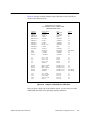
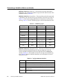
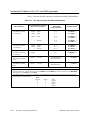
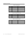
MANUAL PUBLICATION HISTORY
SIMATIC APT Applications Manual
Order Manual Number: PPX:APT--8103--8
Refer to this history in all correspondence and/or discussion about this manual.
Event
Date
Description
Original Issue
Second Edition
Third Edition
Fourth Edition
Fifth Edition
Sixth Edition
Seventh Edition
Eighth Edition
07/91
11/92
02/94
10/94
05/95
10/96
12/98
04/01
Original Issue (2592843--0001)
Second Edition (2592843--0002)
Third Edition (2592843--0003)
Fourth Edition (2592843--0004)
Fifth Edition (2592843--0005)
Sixth Edition (2592843--0006)
Seventh Edition (2592843--0007)
Eighth Edition (2592843--0008)
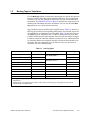
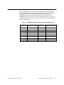
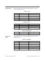
LIST OF EFFECTIVE PAGES
Pages
Cover/Copyright
History/Effective Pages
iii — xiv
1-1 — 1-53
2-1 — 2-18
3-1 — 3-31
4-1 — 4-9
5-1 — 5-9
6-1 — 6-11
7-1 — 7-14
A-1 — A-16
B-1 — B-6
C-1 — C-32
Index-1 — Index-6
Registration
Description
Eighth Edition
Eighth Edition
Eighth Edition
Eighth Edition
Eighth Edition
Eighth Edition
Eighth Edition
Eighth Edition
Eighth Edition
Eighth Edition
Eighth Edition
Eighth Edition
Eighth Edition
Eighth Edition
Eighth Edition
Pages
Description
Trademarks and Copyrights
SIMATICr and SINECr are registered trademarks, and S5t and STEPt are trademarks, of Siemens AG.
386/ATMt, APTt, PCSt, Peerlinkt, Program Master 550t(PM550), Series 500t, Series 505t, TISOFTt, TISTARt, TIWAYt,
CVU1000t, CVU10000t, PM 550t, and Unilinkt are trademarks of Siemens Energy & Automation, Inc.
ASTr is a registered trademark of Bank of America National Trust and Savings Association.
IBMr and ATr are registered trademarks of International Business Machines Corporation.
TUTSIMt is a trademark of Actuality Corporation.
Pentiumr is a registered trademark of the Intel Corporation.
UNIXr is a registered trademark of Novell, Inc.
Windowsr, Windowsr95, Windows NTr, Windowsr2000, Microsoftr, and MS-DOSr are registered trademarks of Microsoft Corporation.
Contents
Preface . . . . . . . . . . . . . . . . . . . . . . . . . . . . . . . . . . . . . . . . . . . . . . . . . . . . . . . . . . . . . . . . .
xiii
Chapter 1
Approach to APT Program Design . . . . . . . . . . . . . . . . . . . . . . . . . . . .
1-1
1.1
What This Chapter Presents . . . . . . . . . . . . . . . . . . . . . . . . . . . . . . . . . . . . . . . . . . . . . . . . . . . . .
1-2
1.2
Develop a Perspective for the Overall Process . . . . . . . . . . . . . . . . . . . . . . . . . . . . . . . . . . . .
1-4
1.3
Do a Top-Down Analysis . . . . . . . . . . . . . . . . . . . . . . . . . . . . . . . . . . . . . . . . . . . . . . . . . . . . . . . .
Consider the Whole Problem, Then Subdivide . . . . . . . . . . . . . . . . . . . . . . . . . . . . . . . . . . . . . . .
Determine What the Process Does . . . . . . . . . . . . . . . . . . . . . . . . . . . . . . . . . . . . . . . . . . . . . . . .
Determine How the Process Is To Be Done . . . . . . . . . . . . . . . . . . . . . . . . . . . . . . . . . . . . . . . . .
Determine Control Needs . . . . . . . . . . . . . . . . . . . . . . . . . . . . . . . . . . . . . . . . . . . . . . . . . . . . . . . . .
Example: Mental Exercise for Top-Down Analysis . . . . . . . . . . . . . . . . . . . . . . . . . . . . . . . . . . . .
1-6
1-6
1-8
1-8
1-10
1-10
1.4
Plan the Bottom-Up Implementation . . . . . . . . . . . . . . . . . . . . . . . . . . . . . . . . . . . . . . . . . . . . .
Use a Layered Approach . . . . . . . . . . . . . . . . . . . . . . . . . . . . . . . . . . . . . . . . . . . . . . . . . . . . . . . . .
Study the Example Program WASH_DEM for Series 505 Controllers . . . . . . . . . . . . . . . . . . .
Coordinating With Operator Interface Design . . . . . . . . . . . . . . . . . . . . . . . . . . . . . . . . . . . . . . . .
1-12
1-12
1-16
1-18
1.5
Create the Code — First Steps . . . . . . . . . . . . . . . . . . . . . . . . . . . . . . . . . . . . . . . . . . . . . . . . . .
Plan Memory Allocation . . . . . . . . . . . . . . . . . . . . . . . . . . . . . . . . . . . . . . . . . . . . . . . . . . . . . . . . . .
Select Naming Convention . . . . . . . . . . . . . . . . . . . . . . . . . . . . . . . . . . . . . . . . . . . . . . . . . . . . . . . .
Plan Testing and Simulation . . . . . . . . . . . . . . . . . . . . . . . . . . . . . . . . . . . . . . . . . . . . . . . . . . . . . . .
Partition the Process into Units . . . . . . . . . . . . . . . . . . . . . . . . . . . . . . . . . . . . . . . . . . . . . . . . . . . .
Select Controller . . . . . . . . . . . . . . . . . . . . . . . . . . . . . . . . . . . . . . . . . . . . . . . . . . . . . . . . . . . . . . . .
Determine I/O Module Layout . . . . . . . . . . . . . . . . . . . . . . . . . . . . . . . . . . . . . . . . . . . . . . . . . . . . .
Configure I/O . . . . . . . . . . . . . . . . . . . . . . . . . . . . . . . . . . . . . . . . . . . . . . . . . . . . . . . . . . . . . . . . . . .
Define Discrete Devices . . . . . . . . . . . . . . . . . . . . . . . . . . . . . . . . . . . . . . . . . . . . . . . . . . . . . . . . . .
1-20
1-20
1-20
1-20
1-20
1-21
1-21
1-21
1-21
1.6
Create the Code — Continuous Control Logic . . . . . . . . . . . . . . . . . . . . . . . . . . . . . . . . . . . .
Program the Simulation Math . . . . . . . . . . . . . . . . . . . . . . . . . . . . . . . . . . . . . . . . . . . . . . . . . . . . .
Program Loops, Analog Alarms, On/Off Control . . . . . . . . . . . . . . . . . . . . . . . . . . . . . . . . . . . . . .
Program Other Continuous Functions . . . . . . . . . . . . . . . . . . . . . . . . . . . . . . . . . . . . . . . . . . . . . .
Program Automatic Start . . . . . . . . . . . . . . . . . . . . . . . . . . . . . . . . . . . . . . . . . . . . . . . . . . . . . . . . .
Program Other Alarms . . . . . . . . . . . . . . . . . . . . . . . . . . . . . . . . . . . . . . . . . . . . . . . . . . . . . . . . . . .
Program Safety and Shutdown Interlocks . . . . . . . . . . . . . . . . . . . . . . . . . . . . . . . . . . . . . . . . . . .
1-22
1-22
1-23
1-24
1-24
1-25
1-25
1.7
Create the Code — Operator Interface Addresses/Graphics . . . . . . . . . . . . . . . . . . . . . . . .
Identify Addresses for Operator Interface Database . . . . . . . . . . . . . . . . . . . . . . . . . . . . . . . . . .
Build Operator Station Database . . . . . . . . . . . . . . . . . . . . . . . . . . . . . . . . . . . . . . . . . . . . . . . . . .
Verify Operator Station Graphics . . . . . . . . . . . . . . . . . . . . . . . . . . . . . . . . . . . . . . . . . . . . . . . . . .
Finish Level 1 Tasks . . . . . . . . . . . . . . . . . . . . . . . . . . . . . . . . . . . . . . . . . . . . . . . . . . . . . . . . . . . . .
1-28
1-28
1-29
1-29
1-29
1.8
Create the Code — Templates for Procedural Control . . . . . . . . . . . . . . . . . . . . . . . . . . . . .
Subordinate SFCs . . . . . . . . . . . . . . . . . . . . . . . . . . . . . . . . . . . . . . . . . . . . . . . . . . . . . . . . . . . . . . .
Main SFC . . . . . . . . . . . . . . . . . . . . . . . . . . . . . . . . . . . . . . . . . . . . . . . . . . . . . . . . . . . . . . . . . . . . . .
1-30
1-30
1-31
Contents
iii
1.9
Create the Code — Recipes and Recipe Templates . . . . . . . . . . . . . . . . . . . . . . . . . . . . . . . .
Build the Template . . . . . . . . . . . . . . . . . . . . . . . . . . . . . . . . . . . . . . . . . . . . . . . . . . . . . . . . . . . . . . .
Build the Recipe . . . . . . . . . . . . . . . . . . . . . . . . . . . . . . . . . . . . . . . . . . . . . . . . . . . . . . . . . . . . . . . . .
Create Data Dictionary . . . . . . . . . . . . . . . . . . . . . . . . . . . . . . . . . . . . . . . . . . . . . . . . . . . . . . . . . . .
1-32
1-32
1-33
1-34
1.10
Create the Code — Procedural Control Logic . . . . . . . . . . . . . . . . . . . . . . . . . . . . . . . . . . . . .
1-36
1.11
Create the Code — Structural Control Logic . . . . . . . . . . . . . . . . . . . . . . . . . . . . . . . . . . . . . .
1-38
1.12
Create the Code — Objective Control Logic . . . . . . . . . . . . . . . . . . . . . . . . . . . . . . . . . . . . . .
Build the Sequence Recipe Template . . . . . . . . . . . . . . . . . . . . . . . . . . . . . . . . . . . . . . . . . . . . . . .
Define the Sequence Recipe Value Names . . . . . . . . . . . . . . . . . . . . . . . . . . . . . . . . . . . . . . . . . .
Build the Sequence Recipe . . . . . . . . . . . . . . . . . . . . . . . . . . . . . . . . . . . . . . . . . . . . . . . . . . . . . . .
Create the Permanent Main SFC . . . . . . . . . . . . . . . . . . . . . . . . . . . . . . . . . . . . . . . . . . . . . . . . . .
Create the Sequence Array . . . . . . . . . . . . . . . . . . . . . . . . . . . . . . . . . . . . . . . . . . . . . . . . . . . . . . .
Create the Procedure Manager SFC . . . . . . . . . . . . . . . . . . . . . . . . . . . . . . . . . . . . . . . . . . . . . . .
Finish Level 2 Tasks . . . . . . . . . . . . . . . . . . . . . . . . . . . . . . . . . . . . . . . . . . . . . . . . . . . . . . . . . . . . .
1-40
1-40
1-41
1-41
1-42
1-43
1-44
1-47
1.13
Create the Code — Level 3 Control . . . . . . . . . . . . . . . . . . . . . . . . . . . . . . . . . . . . . . . . . . . . . .
Add Normal SFCs . . . . . . . . . . . . . . . . . . . . . . . . . . . . . . . . . . . . . . . . . . . . . . . . . . . . . . . . . . . . . . .
Add Safe-State SFCs . . . . . . . . . . . . . . . . . . . . . . . . . . . . . . . . . . . . . . . . . . . . . . . . . . . . . . . . . . . .
Send Additional Data to the Operator Interface . . . . . . . . . . . . . . . . . . . . . . . . . . . . . . . . . . . . . .
Allow Operator to Cancel Operations . . . . . . . . . . . . . . . . . . . . . . . . . . . . . . . . . . . . . . . . . . . . . . .
1-48
1-48
1-49
1-49
1-49
1.14
When You Create Code . . . . . . . . . . . . . . . . . . . . . . . . . . . . . . . . . . . . . . . . . . . . . . . . . . . . . . . . .
Suggestions . . . . . . . . . . . . . . . . . . . . . . . . . . . . . . . . . . . . . . . . . . . . . . . . . . . . . . . . . . . . . . . . . . . .
1-50
1-50
1.15
What Can APT Do for Me? . . . . . . . . . . . . . . . . . . . . . . . . . . . . . . . . . . . . . . . . . . . . . . . . . . . . . .
1-53
Chapter 2
Program Descriptions . . . . . . . . . . . . . . . . . . . . . . . . . . . . . . . . . . . . . . . .
2-1
2.1
Examining the Washer Example . . . . . . . . . . . . . . . . . . . . . . . . . . . . . . . . . . . . . . . . . . . . . . . . .
Loading the Washer Example for Series 505 Controllers . . . . . . . . . . . . . . . . . . . . . . . . . . . . . .
Process Description for the Washer . . . . . . . . . . . . . . . . . . . . . . . . . . . . . . . . . . . . . . . . . . . . . . . .
Process Functions of the Washer . . . . . . . . . . . . . . . . . . . . . . . . . . . . . . . . . . . . . . . . . . . . . . . . . .
P&ID for the Washer . . . . . . . . . . . . . . . . . . . . . . . . . . . . . . . . . . . . . . . . . . . . . . . . . . . . . . . . . . . . .
Process I/O for the Washer . . . . . . . . . . . . . . . . . . . . . . . . . . . . . . . . . . . . . . . . . . . . . . . . . . . . . . .
2-2
2-2
2-4
2-4
2-5
2-6
2.2
Examining the Cooker Example . . . . . . . . . . . . . . . . . . . . . . . . . . . . . . . . . . . . . . . . . . . . . . . . .
Loading the Cooker Example for Series 505 Controllers . . . . . . . . . . . . . . . . . . . . . . . . . . . . . . .
Process Description for the Cooker . . . . . . . . . . . . . . . . . . . . . . . . . . . . . . . . . . . . . . . . . . . . . . . .
Process Functions of the Cooker . . . . . . . . . . . . . . . . . . . . . . . . . . . . . . . . . . . . . . . . . . . . . . . . . .
P&ID for the Cooker . . . . . . . . . . . . . . . . . . . . . . . . . . . . . . . . . . . . . . . . . . . . . . . . . . . . . . . . . . . . .
Process I/O for the Cooker . . . . . . . . . . . . . . . . . . . . . . . . . . . . . . . . . . . . . . . . . . . . . . . . . . . . . . .
2-7
2-7
2-9
2-10
2-12
2-13
2.3
Examining the Heat Exchanger Example . . . . . . . . . . . . . . . . . . . . . . . . . . . . . . . . . . . . . . . . .
Loading the Heat Exchanger Example for Series 505 Controllers . . . . . . . . . . . . . . . . . . . . . . .
Process Description for the Heat Exchanger . . . . . . . . . . . . . . . . . . . . . . . . . . . . . . . . . . . . . . . .
Process Functions of the Heat Exchanger . . . . . . . . . . . . . . . . . . . . . . . . . . . . . . . . . . . . . . . . . .
P&ID for the Heat Exchanger . . . . . . . . . . . . . . . . . . . . . . . . . . . . . . . . . . . . . . . . . . . . . . . . . . . . .
Process I/O for the Heat Exchanger . . . . . . . . . . . . . . . . . . . . . . . . . . . . . . . . . . . . . . . . . . . . . . . .
2-14
2-14
2-15
2-16
2-17
2-18
iv
Contents
Chapter 3
Programming Hints . . . . . . . . . . . . . . . . . . . . . . . . . . . . . . . . . . . . . . . . . .
3-1
3.1
Organization of APT Logic . . . . . . . . . . . . . . . . . . . . . . . . . . . . . . . . . . . . . . . . . . . . . . . . . . . . . .
Understand the Logic Structure . . . . . . . . . . . . . . . . . . . . . . . . . . . . . . . . . . . . . . . . . . . . . . . . . . . .
3-2
3-2
3.2
Math Hints . . . . . . . . . . . . . . . . . . . . . . . . . . . . . . . . . . . . . . . . . . . . . . . . . . . . . . . . . . . . . . . . . . . . .
Avoid Making Same Comparison Twice . . . . . . . . . . . . . . . . . . . . . . . . . . . . . . . . . . . . . . . . . . . . .
Use Boolean Logic when Possible . . . . . . . . . . . . . . . . . . . . . . . . . . . . . . . . . . . . . . . . . . . . . . . . .
Write Clear and Readable Code . . . . . . . . . . . . . . . . . . . . . . . . . . . . . . . . . . . . . . . . . . . . . . . . . . .
Use Event Math CFBs . . . . . . . . . . . . . . . . . . . . . . . . . . . . . . . . . . . . . . . . . . . . . . . . . . . . . . . . . . .
Use Active Versus Continuous Option . . . . . . . . . . . . . . . . . . . . . . . . . . . . . . . . . . . . . . . . . . . . . .
RLL Math Is Processed Faster than SF Math for Series 505 Controllers . . . . . . . . . . . . . . . . .
Consolidate CFB Math for Series 505 Controllers . . . . . . . . . . . . . . . . . . . . . . . . . . . . . . . . . . . .
3-3
3-3
3-3
3-4
3-5
3-5
3-6
3-7
3.3
SF Program/Loop/Analog Alarm Hints for Series 505 Controllers . . . . . . . . . . . . . . . . . . .
How Priority for SF Tasks Is Determined for Series 505 Controllers . . . . . . . . . . . . . . . . . . . . .
Detecting Task Overruns . . . . . . . . . . . . . . . . . . . . . . . . . . . . . . . . . . . . . . . . . . . . . . . . . . . . . . . . .
Handling Task Overruns . . . . . . . . . . . . . . . . . . . . . . . . . . . . . . . . . . . . . . . . . . . . . . . . . . . . . . . . . .
Correlating Loop and Real Math Processing . . . . . . . . . . . . . . . . . . . . . . . . . . . . . . . . . . . . . . . . .
3-8
3-8
3-10
3-11
3-12
3.4
Recipe Hints . . . . . . . . . . . . . . . . . . . . . . . . . . . . . . . . . . . . . . . . . . . . . . . . . . . . . . . . . . . . . . . . . . .
Avoid Using Boolean Variables as Recipe Elements . . . . . . . . . . . . . . . . . . . . . . . . . . . . . . . . . .
3-13
3-13
3.5
Hints for Using Debug . . . . . . . . . . . . . . . . . . . . . . . . . . . . . . . . . . . . . . . . . . . . . . . . . . . . . . . . . .
Charts . . . . . . . . . . . . . . . . . . . . . . . . . . . . . . . . . . . . . . . . . . . . . . . . . . . . . . . . . . . . . . . . . . . . . . . . .
3-14
3-14
3.6
Miscellaneous Hints . . . . . . . . . . . . . . . . . . . . . . . . . . . . . . . . . . . . . . . . . . . . . . . . . . . . . . . . . . . .
Guidelines for More Efficient Use of APT . . . . . . . . . . . . . . . . . . . . . . . . . . . . . . . . . . . . . . . . . . .
Avoid Overuse of Timers in SFCs . . . . . . . . . . . . . . . . . . . . . . . . . . . . . . . . . . . . . . . . . . . . . . . . . .
Control Relay Allocation for Series 505 Controllers . . . . . . . . . . . . . . . . . . . . . . . . . . . . . . . . . . .
Using Commands, Flags, and Extensions . . . . . . . . . . . . . . . . . . . . . . . . . . . . . . . . . . . . . . . . . . .
Group the Interlock Functions . . . . . . . . . . . . . . . . . . . . . . . . . . . . . . . . . . . . . . . . . . . . . . . . . . . . .
Programming Safe-State SFCs . . . . . . . . . . . . . . . . . . . . . . . . . . . . . . . . . . . . . . . . . . . . . . . . . . . .
Program Download: Redundancy Constraints . . . . . . . . . . . . . . . . . . . . . . . . . . . . . . . . . . . . . . .
If You Need More L-Memory or Faster RLL Execution for Series 505 Controllers... . . . . . . . .
If You Need Faster STL Execution for S5 Controllers... . . . . . . . . . . . . . . . . . . . . . . . . . . . . . . . .
Program Recovery from Controller Power Loss . . . . . . . . . . . . . . . . . . . . . . . . . . . . . . . . . . . . . .
3-15
3-15
3-16
3-16
3-17
3-17
3-19
3-19
3-20
3-20
3-21
3.7
Configuring Devices . . . . . . . . . . . . . . . . . . . . . . . . . . . . . . . . . . . . . . . . . . . . . . . . . . . . . . . . . . . .
Configuring Simple Devices . . . . . . . . . . . . . . . . . . . . . . . . . . . . . . . . . . . . . . . . . . . . . . . . . . . . . . .
Using Pseudo Devices . . . . . . . . . . . . . . . . . . . . . . . . . . . . . . . . . . . . . . . . . . . . . . . . . . . . . . . . . . .
3-23
3-23
3-24
3.8
Table and I/O Hints . . . . . . . . . . . . . . . . . . . . . . . . . . . . . . . . . . . . . . . . . . . . . . . . . . . . . . . . . . . . .
Working in Tables . . . . . . . . . . . . . . . . . . . . . . . . . . . . . . . . . . . . . . . . . . . . . . . . . . . . . . . . . . . . . . .
Configuring Unlisted I/O Modules for Series 505 . . . . . . . . . . . . . . . . . . . . . . . . . . . . . . . . . . . . .
Configuring the PEERLINK Module for Series 505 Controllers . . . . . . . . . . . . . . . . . . . . . . . . .
Configuring the HSPI and HSC Modules for Series 505 Controllers . . . . . . . . . . . . . . . . . . . . .
Configuring ET200 . . . . . . . . . . . . . . . . . . . . . . . . . . . . . . . . . . . . . . . . . . . . . . . . . . . . . . . . . . . . . .
3-25
3-25
3-25
3-25
3-25
3-25
Contents
v
3.9
OSx Hints . . . . . . . . . . . . . . . . . . . . . . . . . . . . . . . . . . . . . . . . . . . . . . . . . . . . . . . . . . . . . . . . . . . . .
Selecting APT Object Names . . . . . . . . . . . . . . . . . . . . . . . . . . . . . . . . . . . . . . . . . . . . . . . . . . . . .
Selecting Array Names . . . . . . . . . . . . . . . . . . . . . . . . . . . . . . . . . . . . . . . . . . . . . . . . . . . . . . . . . . .
Selecting Recipe Names . . . . . . . . . . . . . . . . . . . . . . . . . . . . . . . . . . . . . . . . . . . . . . . . . . . . . . . . .
Selecting Unit Names . . . . . . . . . . . . . . . . . . . . . . . . . . . . . . . . . . . . . . . . . . . . . . . . . . . . . . . . . . . .
Animating Non-Standard Symbols . . . . . . . . . . . . . . . . . . . . . . . . . . . . . . . . . . . . . . . . . . . . . . . . .
Validation Failure . . . . . . . . . . . . . . . . . . . . . . . . . . . . . . . . . . . . . . . . . . . . . . . . . . . . . . . . . . . . . . . .
3-26
3-26
3-27
3-27
3-28
3-29
3-29
3.10
Relating APT and the Non-OSx Operator Interface Database . . . . . . . . . . . . . . . . . . . . . . .
3-30
3.11
Recommendations to the CVU1000/10000 User . . . . . . . . . . . . . . . . . . . . . . . . . . . . . . . . . . .
3-31
Chapter 4
APT and Controller Memory . . . . . . . . . . . . . . . . . . . . . . . . . . . . . . . . . .
4-1
4.1
Overview . . . . . . . . . . . . . . . . . . . . . . . . . . . . . . . . . . . . . . . . . . . . . . . . . . . . . . . . . . . . . . . . . . . . . .
Source Code . . . . . . . . . . . . . . . . . . . . . . . . . . . . . . . . . . . . . . . . . . . . . . . . . . . . . . . . . . . . . . . . . . .
Downloaded Program . . . . . . . . . . . . . . . . . . . . . . . . . . . . . . . . . . . . . . . . . . . . . . . . . . . . . . . . . . . .
4-2
4-2
4-3
4.2
Memory and I/O Usage . . . . . . . . . . . . . . . . . . . . . . . . . . . . . . . . . . . . . . . . . . . . . . . . . . . . . . . . . .
Overview . . . . . . . . . . . . . . . . . . . . . . . . . . . . . . . . . . . . . . . . . . . . . . . . . . . . . . . . . . . . . . . . . . . . . . .
Reserving Memory . . . . . . . . . . . . . . . . . . . . . . . . . . . . . . . . . . . . . . . . . . . . . . . . . . . . . . . . . . . . . .
Guidelines for Series 505 Controllers . . . . . . . . . . . . . . . . . . . . . . . . . . . . . . . . . . . . . . . . . . . . . . .
Changing Values in Memory . . . . . . . . . . . . . . . . . . . . . . . . . . . . . . . . . . . . . . . . . . . . . . . . . . . . . .
Reserving I/O Locations in Series 505 Controllers . . . . . . . . . . . . . . . . . . . . . . . . . . . . . . . . . . . .
Determining Memory and I/O Usage . . . . . . . . . . . . . . . . . . . . . . . . . . . . . . . . . . . . . . . . . . . . . . .
Loops and Analog Alarms . . . . . . . . . . . . . . . . . . . . . . . . . . . . . . . . . . . . . . . . . . . . . . . . . . . . . . . .
4-4
4-4
4-4
4-5
4-6
4-7
4-8
4-8
Chapter 5
Dynamic Program Simulation . . . . . . . . . . . . . . . . . . . . . . . . . . . . . . . . .
5-1
5.1
Testing the Application Program . . . . . . . . . . . . . . . . . . . . . . . . . . . . . . . . . . . . . . . . . . . . . . . .
Manual Testing . . . . . . . . . . . . . . . . . . . . . . . . . . . . . . . . . . . . . . . . . . . . . . . . . . . . . . . . . . . . . . . . . .
Repeatable Logic Testing . . . . . . . . . . . . . . . . . . . . . . . . . . . . . . . . . . . . . . . . . . . . . . . . . . . . . . . . .
Dynamic Simulation . . . . . . . . . . . . . . . . . . . . . . . . . . . . . . . . . . . . . . . . . . . . . . . . . . . . . . . . . . . . .
5-2
5-2
5-2
5-3
5.2
APT and the TUTSIM Dynamic Simulation Package (Series 505) . . . . . . . . . . . . . . . . . . . .
Availability . . . . . . . . . . . . . . . . . . . . . . . . . . . . . . . . . . . . . . . . . . . . . . . . . . . . . . . . . . . . . . . . . . . . . .
APT/TUTSIM Block . . . . . . . . . . . . . . . . . . . . . . . . . . . . . . . . . . . . . . . . . . . . . . . . . . . . . . . . . . . . . .
TUTSIM.USR File . . . . . . . . . . . . . . . . . . . . . . . . . . . . . . . . . . . . . . . . . . . . . . . . . . . . . . . . . . . . . . .
Example TUTSIM Program for Series 505 . . . . . . . . . . . . . . . . . . . . . . . . . . . . . . . . . . . . . . . . . .
Block Diagram Examples . . . . . . . . . . . . . . . . . . . . . . . . . . . . . . . . . . . . . . . . . . . . . . . . . . . . . . . . .
5-4
5-4
5-5
5-6
5-8
5-9
Chapter 6
Redundant Configuration for S5 . . . . . . . . . . . . . . . . . . . . . . . . . . . . . .
6-1
6.1
Configuring an S5--155H Redundant System for APT . . . . . . . . . . . . . . . . . . . . . . . . . . . . . .
Overview . . . . . . . . . . . . . . . . . . . . . . . . . . . . . . . . . . . . . . . . . . . . . . . . . . . . . . . . . . . . . . . . . . . . . . .
Options for Setting Up Your Redundant Configuration . . . . . . . . . . . . . . . . . . . . . . . . . . . . . . . .
Generating an APT Address Report and Configuring COM 155H . . . . . . . . . . . . . . . . . . . . . . .
6-2
6-2
6-2
6-3
6.2
Generating an APT Address Report . . . . . . . . . . . . . . . . . . . . . . . . . . . . . . . . . . . . . . . . . . . . . .
6-4
6.3
Configuring Operating System Parameters from COM 155H . . . . . . . . . . . . . . . . . . . . . . .
Operating System (SYSTEM) Parameters . . . . . . . . . . . . . . . . . . . . . . . . . . . . . . . . . . . . . . . . . .
6-6
6-6
vi
Contents
6.4
Configuring Data Block Transfer Lists from COM 155H . . . . . . . . . . . . . . . . . . . . . . . . . . . .
Transfer Data for Activating Standby (TRAFDAT) . . . . . . . . . . . . . . . . . . . . . . . . . . . . . . . . . . . .
6-8
6-8
6.5
Configuring Expansion Units from COM 155H . . . . . . . . . . . . . . . . . . . . . . . . . . . . . . . . . . . .
Configuring Expansion Units (I/O 314) . . . . . . . . . . . . . . . . . . . . . . . . . . . . . . . . . . . . . . . . . . . . . .
6-10
6-10
6.6
Configuring I/O from COM 155H . . . . . . . . . . . . . . . . . . . . . . . . . . . . . . . . . . . . . . . . . . . . . . . . .
IOCONF . . . . . . . . . . . . . . . . . . . . . . . . . . . . . . . . . . . . . . . . . . . . . . . . . . . . . . . . . . . . . . . . . . . . . . .
6-11
6-11
Chapter 7
APT and the OSx Operator Interface . . . . . . . . . . . . . . . . . . . . . . . . . . .
7-1
7.1
Using APT to Configure an OSx Database . . . . . . . . . . . . . . . . . . . . . . . . . . . . . . . . . . . . . . . .
7-2
7.2
Marking Tags for Translation . . . . . . . . . . . . . . . . . . . . . . . . . . . . . . . . . . . . . . . . . . . . . . . . . . . .
Recommendations for Marking Objects . . . . . . . . . . . . . . . . . . . . . . . . . . . . . . . . . . . . . . . . . . . . .
7-5
7-8
7.3
Compiling the Program . . . . . . . . . . . . . . . . . . . . . . . . . . . . . . . . . . . . . . . . . . . . . . . . . . . . . . . . .
Recommendations for Compiling a Program . . . . . . . . . . . . . . . . . . . . . . . . . . . . . . . . . . . . . . . . .
Report by Exception . . . . . . . . . . . . . . . . . . . . . . . . . . . . . . . . . . . . . . . . . . . . . . . . . . . . . . . . . . . . .
Reserving Memory for RBE (Series 505) . . . . . . . . . . . . . . . . . . . . . . . . . . . . . . . . . . . . . . . . . . . .
7-9
7-10
7-12
7-12
7.4
Translating Tags . . . . . . . . . . . . . . . . . . . . . . . . . . . . . . . . . . . . . . . . . . . . . . . . . . . . . . . . . . . . . . .
7-14
Appendix A Defining a Variable’s Address . . . . . . . . . . . . . . . . . . . . . . . . . . . . . . .
A-1
A.1
Determining a Variable’s Address . . . . . . . . . . . . . . . . . . . . . . . . . . . . . . . . . . . . . . . . . . . . . . . .
Reading Translated Tag Reports . . . . . . . . . . . . . . . . . . . . . . . . . . . . . . . . . . . . . . . . . . . . . . . . . . .
Using Debug . . . . . . . . . . . . . . . . . . . . . . . . . . . . . . . . . . . . . . . . . . . . . . . . . . . . . . . . . . . . . . . . . . .
Reading Symbol/Address Reports . . . . . . . . . . . . . . . . . . . . . . . . . . . . . . . . . . . . . . . . . . . . . . . . .
Using the APT DC Utility . . . . . . . . . . . . . . . . . . . . . . . . . . . . . . . . . . . . . . . . . . . . . . . . . . . . . . . . .
Reading the INSTALL.TAG File for TISTAR Release 1.x and 2.x (Series 505) . . . . . . . . . . . .
Reading the INSTALL.TAG File for PCS Release 3.x or OSx Rel. 4.x . . . . . . . . . . . . . . . . . . .
An Analysis of the INSTALL.TAG File Examples for PCS/OSx . . . . . . . . . . . . . . . . . . . . . . . . .
A-2
A-2
A-2
A-3
A-4
A-5
A-10
A-14
Appendix B Extensions Fixed by the Compile . . . . . . . . . . . . . . . . . . . . . . . . . . .
B-1
Appendix C OSx, PCS, and TISTAR Tag Translation . . . . . . . . . . . . . . . . . . . . . .
C-1
C.1
C-2
C-2
C-4
C-4
C-6
C-8
C-8
C-10
C-12
C-15
C-17
C-19
C-19
C-22
Translating APT Objects to OSx, PCS, and TISTAR . . . . . . . . . . . . . . . . . . . . . . . . . . . . . . . .
Overview . . . . . . . . . . . . . . . . . . . . . . . . . . . . . . . . . . . . . . . . . . . . . . . . . . . . . . . . . . . . . . . . . . . . . . .
Units . . . . . . . . . . . . . . . . . . . . . . . . . . . . . . . . . . . . . . . . . . . . . . . . . . . . . . . . . . . . . . . . . . . . . . . . . .
Batch Unit Tags . . . . . . . . . . . . . . . . . . . . . . . . . . . . . . . . . . . . . . . . . . . . . . . . . . . . . . . . . . . . . . . . .
Devices . . . . . . . . . . . . . . . . . . . . . . . . . . . . . . . . . . . . . . . . . . . . . . . . . . . . . . . . . . . . . . . . . . . . . . . .
Correlating APT Device Types with OSx/PCS Attributes . . . . . . . . . . . . . . . . . . . . . . . . . . . . . .
Translating Tags for OSx/PCS MTR1 . . . . . . . . . . . . . . . . . . . . . . . . . . . . . . . . . . . . . . . . . . . . . . .
Translating Tags for OSx/PCS RMTR . . . . . . . . . . . . . . . . . . . . . . . . . . . . . . . . . . . . . . . . . . . . . .
Translating Tags for OSx/PCS MTR2 . . . . . . . . . . . . . . . . . . . . . . . . . . . . . . . . . . . . . . . . . . . . . . .
Translating Tags for OSx/PCS VLV1 . . . . . . . . . . . . . . . . . . . . . . . . . . . . . . . . . . . . . . . . . . . . . . .
Translating Tags for OSx/PCS VLV2 . . . . . . . . . . . . . . . . . . . . . . . . . . . . . . . . . . . . . . . . . . . . . . .
I/O . . . . . . . . . . . . . . . . . . . . . . . . . . . . . . . . . . . . . . . . . . . . . . . . . . . . . . . . . . . . . . . . . . . . . . . . . . . .
Declarations . . . . . . . . . . . . . . . . . . . . . . . . . . . . . . . . . . . . . . . . . . . . . . . . . . . . . . . . . . . . . . . . . . . .
Recipes . . . . . . . . . . . . . . . . . . . . . . . . . . . . . . . . . . . . . . . . . . . . . . . . . . . . . . . . . . . . . . . . . . . . . . . .
Contents
vii
C.2
CFB Extensions . . . . . . . . . . . . . . . . . . . . . . . . . . . . . . . . . . . . . . . . . . . . . . . . . . . . . . . . . . . . . . . .
Advanced Blocks . . . . . . . . . . . . . . . . . . . . . . . . . . . . . . . . . . . . . . . . . . . . . . . . . . . . . . . . . . . . . . . .
Dynamic Blocks . . . . . . . . . . . . . . . . . . . . . . . . . . . . . . . . . . . . . . . . . . . . . . . . . . . . . . . . . . . . . . . . .
Limiter Blocks . . . . . . . . . . . . . . . . . . . . . . . . . . . . . . . . . . . . . . . . . . . . . . . . . . . . . . . . . . . . . . . . . . .
Math Blocks . . . . . . . . . . . . . . . . . . . . . . . . . . . . . . . . . . . . . . . . . . . . . . . . . . . . . . . . . . . . . . . . . . . .
Other Blocks . . . . . . . . . . . . . . . . . . . . . . . . . . . . . . . . . . . . . . . . . . . . . . . . . . . . . . . . . . . . . . . . . . . .
Selector Blocks . . . . . . . . . . . . . . . . . . . . . . . . . . . . . . . . . . . . . . . . . . . . . . . . . . . . . . . . . . . . . . . . .
Standard Blocks . . . . . . . . . . . . . . . . . . . . . . . . . . . . . . . . . . . . . . . . . . . . . . . . . . . . . . . . . . . . . . . .
Valve Control Blocks . . . . . . . . . . . . . . . . . . . . . . . . . . . . . . . . . . . . . . . . . . . . . . . . . . . . . . . . . . . . .
C-23
C-23
C-25
C-26
C-27
C-28
C-29
C-31
C-31
Index . . . . . . . . . . . . . . . . . . . . . . . . . . . . . . . . . . . . . . . . . . . . . . . . . . . . . . . . . . . . . . . . Index-1
viii
Contents
List of Figures
1-1
1-2
1-3
1-4
1-5
1-6
1-7
1-8
1-9
1-10
1-11
1-12
1-13
1-14
1-15
1-16
1-17
1-18
1-19
1-20
1-21
1-22
1-23
1-24
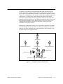
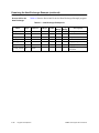
Partitioning by Function or by Task . . . . . . . . . . . . . . . . . . . . . . . . . . . . . . . . . . . . . . . . . . . . . . . . .
Determine the Process Tasks . . . . . . . . . . . . . . . . . . . . . . . . . . . . . . . . . . . . . . . . . . . . . . . . . . . . .
Example of Control Determination . . . . . . . . . . . . . . . . . . . . . . . . . . . . . . . . . . . . . . . . . . . . . . . . .
Tasks Comprising the Bottom-Up Implementation . . . . . . . . . . . . . . . . . . . . . . . . . . . . . . . . . . . .
Steps of Designing Process Control . . . . . . . . . . . . . . . . . . . . . . . . . . . . . . . . . . . . . . . . . . . . . . . .
Example of CFC Groupings . . . . . . . . . . . . . . . . . . . . . . . . . . . . . . . . . . . . . . . . . . . . . . . . . . . . . . .
Example Interlock Blocks . . . . . . . . . . . . . . . . . . . . . . . . . . . . . . . . . . . . . . . . . . . . . . . . . . . . . . . . .
Example Interlock Groupings . . . . . . . . . . . . . . . . . . . . . . . . . . . . . . . . . . . . . . . . . . . . . . . . . . . . . .
Example SFC Templates . . . . . . . . . . . . . . . . . . . . . . . . . . . . . . . . . . . . . . . . . . . . . . . . . . . . . . . . .
Example Procedure Activator SFC . . . . . . . . . . . . . . . . . . . . . . . . . . . . . . . . . . . . . . . . . . . . . . . . .
Example Recipe Template . . . . . . . . . . . . . . . . . . . . . . . . . . . . . . . . . . . . . . . . . . . . . . . . . . . . . . . .
Example Recipe . . . . . . . . . . . . . . . . . . . . . . . . . . . . . . . . . . . . . . . . . . . . . . . . . . . . . . . . . . . . . . . . .
Example Data Dictionary Template . . . . . . . . . . . . . . . . . . . . . . . . . . . . . . . . . . . . . . . . . . . . . . . . .
Example Data Dictionary Recipe . . . . . . . . . . . . . . . . . . . . . . . . . . . . . . . . . . . . . . . . . . . . . . . . . .
Example Procedure SFC . . . . . . . . . . . . . . . . . . . . . . . . . . . . . . . . . . . . . . . . . . . . . . . . . . . . . . . . .
Example Procedure Activator SFC . . . . . . . . . . . . . . . . . . . . . . . . . . . . . . . . . . . . . . . . . . . . . . . . .
Relationship of the Procedure Activator to Procedural SFCs . . . . . . . . . . . . . . . . . . . . . . . . . . .
Example Sequence Recipe Template . . . . . . . . . . . . . . . . . . . . . . . . . . . . . . . . . . . . . . . . . . . . . . .
Example Sequence Recipe . . . . . . . . . . . . . . . . . . . . . . . . . . . . . . . . . . . . . . . . . . . . . . . . . . . . . . .
Example Main SFC . . . . . . . . . . . . . . . . . . . . . . . . . . . . . . . . . . . . . . . . . . . . . . . . . . . . . . . . . . . . . .
Example Procedure Manager SFC . . . . . . . . . . . . . . . . . . . . . . . . . . . . . . . . . . . . . . . . . . . . . . . . .
Sequential Control Hierarchical Relationship . . . . . . . . . . . . . . . . . . . . . . . . . . . . . . . . . . . . . . . .
APT Hierarchical Relationship . . . . . . . . . . . . . . . . . . . . . . . . . . . . . . . . . . . . . . . . . . . . . . . . . . . . .
Project Development/Time Relationship . . . . . . . . . . . . . . . . . . . . . . . . . . . . . . . . . . . . . . . . . . . .
1-7
1-9
1-11
1-15
1-18
1-23
1-25
1-26
1-30
1-31
1-32
1-33
1-34
1-35
1-37
1-38
1-39
1-40
1-41
1-43
1-45
1-46
1-47
1-48
2-1
2-2
2-3
Washer Example P&ID . . . . . . . . . . . . . . . . . . . . . . . . . . . . . . . . . . . . . . . . . . . . . . . . . . . . . . . . . . .
Cooker Example P&ID . . . . . . . . . . . . . . . . . . . . . . . . . . . . . . . . . . . . . . . . . . . . . . . . . . . . . . . . . . .
Heat Exchanger Example P&ID . . . . . . . . . . . . . . . . . . . . . . . . . . . . . . . . . . . . . . . . . . . . . . . . . . .
2-5
2-12
2-17
3-1
3-2
3-3
3-4
3-5
3-6
3-7
3-8
3-9
3-10
3-11
3-12
3-13
Organization of APT Logic in RLL or STL . . . . . . . . . . . . . . . . . . . . . . . . . . . . . . . . . . . . . . . . . . .
Example of Reducing Math Comparisons . . . . . . . . . . . . . . . . . . . . . . . . . . . . . . . . . . . . . . . . . . .
Use Boolean Logic for Speed . . . . . . . . . . . . . . . . . . . . . . . . . . . . . . . . . . . . . . . . . . . . . . . . . . . . .
Logic Differences between If/Then and Boolean Logic . . . . . . . . . . . . . . . . . . . . . . . . . . . . . . . .
Write Code Clearly . . . . . . . . . . . . . . . . . . . . . . . . . . . . . . . . . . . . . . . . . . . . . . . . . . . . . . . . . . . . . .
Use Parentheses in Math . . . . . . . . . . . . . . . . . . . . . . . . . . . . . . . . . . . . . . . . . . . . . . . . . . . . . . . . .
Indent Math Code . . . . . . . . . . . . . . . . . . . . . . . . . . . . . . . . . . . . . . . . . . . . . . . . . . . . . . . . . . . . . . .
Use Event Math Blocks to Create Cyclic Events . . . . . . . . . . . . . . . . . . . . . . . . . . . . . . . . . . . . .
Calculation Requiring SF Program . . . . . . . . . . . . . . . . . . . . . . . . . . . . . . . . . . . . . . . . . . . . . . . . .
Consolidate CFB Math . . . . . . . . . . . . . . . . . . . . . . . . . . . . . . . . . . . . . . . . . . . . . . . . . . . . . . . . . . .
Status Word 162 . . . . . . . . . . . . . . . . . . . . . . . . . . . . . . . . . . . . . . . . . . . . . . . . . . . . . . . . . . . . . . . .
Consolidate Math Functions . . . . . . . . . . . . . . . . . . . . . . . . . . . . . . . . . . . . . . . . . . . . . . . . . . . . . .
Use a Timer More than Once . . . . . . . . . . . . . . . . . . . . . . . . . . . . . . . . . . . . . . . . . . . . . . . . . . . . .
3-2
3-3
3-3
3-3
3-4
3-4
3-4
3-5
3-6
3-7
3-10
3-12
3-16
Contents
ix
List of Figures (continued)
3-14
3-15
Example of Interlock Logic . . . . . . . . . . . . . . . . . . . . . . . . . . . . . . . . . . . . . . . . . . . . . . . . . . . . . . . .
Example of a Pseudo Device . . . . . . . . . . . . . . . . . . . . . . . . . . . . . . . . . . . . . . . . . . . . . . . . . . . . . .
3-18
3-24
5-1
5-2
5-3
5-4
5-5
5-6
APT/TUTSIM USR Block . . . . . . . . . . . . . . . . . . . . . . . . . . . . . . . . . . . . . . . . . . . . . . . . . . . . . . . . .
TUTSIM.USR File Format . . . . . . . . . . . . . . . . . . . . . . . . . . . . . . . . . . . . . . . . . . . . . . . . . . . . . . . .
Example TUTSIM.USR File . . . . . . . . . . . . . . . . . . . . . . . . . . . . . . . . . . . . . . . . . . . . . . . . . . . . . . .
Example TUTSIM Program and TUTSIM.USR File . . . . . . . . . . . . . . . . . . . . . . . . . . . . . . . . . . .
Example TUTSIM Algorithm for Mass Balance . . . . . . . . . . . . . . . . . . . . . . . . . . . . . . . . . . . . . . .
Example TUTSIM Algorithm for a PID Loop . . . . . . . . . . . . . . . . . . . . . . . . . . . . . . . . . . . . . . . . .
5-5
5-6
5-7
5-8
5-9
5-9
6-1
6-2
6-3
6-4
6-5
Creating an Address Report . . . . . . . . . . . . . . . . . . . . . . . . . . . . . . . . . . . . . . . . . . . . . . . . . . . . . .
Analysis of DBs/DXs for COM 155H . . . . . . . . . . . . . . . . . . . . . . . . . . . . . . . . . . . . . . . . . . . . . . .
Initialize Operating System Screen . . . . . . . . . . . . . . . . . . . . . . . . . . . . . . . . . . . . . . . . . . . . . . . . .
Values Required by APT . . . . . . . . . . . . . . . . . . . . . . . . . . . . . . . . . . . . . . . . . . . . . . . . . . . . . . . . .
Analysis of DBs/DXs for COM 155H . . . . . . . . . . . . . . . . . . . . . . . . . . . . . . . . . . . . . . . . . . . . . . .
6-4
6-5
6-6
6-7
6-9
7-1
Portion of an Example INSTALL.TAG File for PCS 3.x . . . . . . . . . . . . . . . . . . . . . . . . . . . . . . . .
7-3
A-1
A-2
A-3
Format for an N Line in the INSTALL.TAG File for TISTAR 1.x and 2.x . . . . . . . . . . . . . . . . . .
INSTALL.TAG File Example for PCS 3.x and OSx 4.x . . . . . . . . . . . . . . . . . . . . . . . . . . . . . . . . .
INSTALL.TAG File Spreadsheet Example for PCS 3.x and OSx 4.x . . . . . . . . . . . . . . . . . . . . .
A-9
A-11
A-12
C-1
C-2
C-3
C-4
C-5
APT Tag Correlation with OSx MTR1 Status Word . . . . . . . . . . . . . . . . . . . . . . . . . . . . . . . . . . . . .
APT Tag Correlation with OSx RMTR Status Word . . . . . . . . . . . . . . . . . . . . . . . . . . . . . . . . . . . . .
APT Tag Correlation with OSx MTR2 Status Word . . . . . . . . . . . . . . . . . . . . . . . . . . . . . . . . . . . . .
APT Tag Correlation with OSx VLV1 . . . . . . . . . . . . . . . . . . . . . . . . . . . . . . . . . . . . . . . . . . . . . . . . .
APT Tag Correlation with OSx VLV2 . . . . . . . . . . . . . . . . . . . . . . . . . . . . . . . . . . . . . . . . . . . . . . . . .
C-8
C-10
C-12
C-15
C-17
x
Contents
List of Tables
1-1
1-2
CFCs Reflect Control Strategies . . . . . . . . . . . . . . . . . . . . . . . . . . . . . . . . . . . . . . . . . . . . . . . . . . .
Uses for the .NRDY Extension . . . . . . . . . . . . . . . . . . . . . . . . . . . . . . . . . . . . . . . . . . . . . . . . . . . .
1-22
1-27
2-1
2-2
2-3
Washer Example I/O . . . . . . . . . . . . . . . . . . . . . . . . . . . . . . . . . . . . . . . . . . . . . . . . . . . . . . . . . . . . .
Cooker Example I/O . . . . . . . . . . . . . . . . . . . . . . . . . . . . . . . . . . . . . . . . . . . . . . . . . . . . . . . . . . . . .
Heat Exchanger Example I/O . . . . . . . . . . . . . . . . . . . . . . . . . . . . . . . . . . . . . . . . . . . . . . . . . . . . .
2-6
2-13
2-18
6-1
How APT I/O Types Map to S5 . . . . . . . . . . . . . . . . . . . . . . . . . . . . . . . . . . . . . . . . . . . . . . . . . . . .
6-11
7-1
7-2
7-3
OSx Tag Types . . . . . . . . . . . . . . . . . . . . . . . . . . . . . . . . . . . . . . . . . . . . . . . . . . . . . . . . . . . . . . . . .
Objects Used as Special Configuration Tools for OSx . . . . . . . . . . . . . . . . . . . . . . . . . . . . . . . . .
RBE Memory Requirements for Series 505 Controllers . . . . . . . . . . . . . . . . . . . . . . . . . . . . . . .
7-5
7-6
7-13
A-1
A-2
A-3
A-4
A-5
INSTALL.TAG File Example for TISTAR Release 1.x and 2.x . . . . . . . . . . . . . . . . . . . . . . . . . .
TISTAR Tag Types . . . . . . . . . . . . . . . . . . . . . . . . . . . . . . . . . . . . . . . . . . . . . . . . . . . . . . . . . . . . . .
Tag Type Attribute Identifiers . . . . . . . . . . . . . . . . . . . . . . . . . . . . . . . . . . . . . . . . . . . . . . . . . . . . . .
Identifiers for Tag Types . . . . . . . . . . . . . . . . . . . . . . . . . . . . . . . . . . . . . . . . . . . . . . . . . . . . . . . . . .
Identifiers for Attributes of Tags . . . . . . . . . . . . . . . . . . . . . . . . . . . . . . . . . . . . . . . . . . . . . . . . . . . .
A-6
A-8
A-8
A-15
A-15
A-6
PCS/OSx Tag Types . . . . . . . . . . . . . . . . . . . . . . . . . . . . . . . . . . . . . . . . . . . . . . . . . . . . . . . . . . . . .
A-16
C-1
C-2
C-3
C-4
C-5
C-6
Unit Tag Types and Extensions . . . . . . . . . . . . . . . . . . . . . . . . . . . . . . . . . . . . . . . . . . . . . . . . . . . .
Batch Unit Tag Attributes . . . . . . . . . . . . . . . . . . . . . . . . . . . . . . . . . . . . . . . . . . . . . . . . . . . . . . . . .
Valves . . . . . . . . . . . . . . . . . . . . . . . . . . . . . . . . . . . . . . . . . . . . . . . . . . . . . . . . . . . . . . . . . . . . . . . . .
Cylinders . . . . . . . . . . . . . . . . . . . . . . . . . . . . . . . . . . . . . . . . . . . . . . . . . . . . . . . . . . . . . . . . . . . . . . .
Motors . . . . . . . . . . . . . . . . . . . . . . . . . . . . . . . . . . . . . . . . . . . . . . . . . . . . . . . . . . . . . . . . . . . . . . . . .
Presses . . . . . . . . . . . . . . . . . . . . . . . . . . . . . . . . . . . . . . . . . . . . . . . . . . . . . . . . . . . . . . . . . . . . . . . .
C-4
C-5
C-6
C-6
C-6
C-7
C-7
C-8
C-9
C-10
C-11
C-12
C-13
C-14
C-15
C-16
C-17
C-18
Stopwatch Timer . . . . . . . . . . . . . . . . . . . . . . . . . . . . . . . . . . . . . . . . . . . . . . . . . . . . . . . . . . . . . . . .
APT Tag Correlation with OSx MTR1 Attributes . . . . . . . . . . . . . . . . . . . . . . . . . . . . . . . . . . . . . .
APT Tag Correlation with OSx RMTR Attributes . . . . . . . . . . . . . . . . . . . . . . . . . . . . . . . . . . . . . .
OSx MTR2 Status Correlation with APT Extensions . . . . . . . . . . . . . . . . . . . . . . . . . . . . . . . . . .
APT Tag Correlation with OSx MTR2 Attributes . . . . . . . . . . . . . . . . . . . . . . . . . . . . . . . . . . . . . .
APT Tag Correlation with OSx VLV1 Attributes . . . . . . . . . . . . . . . . . . . . . . . . . . . . . . . . . . . . . . .
APT Tag Correlation with OSx VLV2 Attributes . . . . . . . . . . . . . . . . . . . . . . . . . . . . . . . . . . . . . . .
I/O . . . . . . . . . . . . . . . . . . . . . . . . . . . . . . . . . . . . . . . . . . . . . . . . . . . . . . . . . . . . . . . . . . . . . . . . . . . .
Declarations . . . . . . . . . . . . . . . . . . . . . . . . . . . . . . . . . . . . . . . . . . . . . . . . . . . . . . . . . . . . . . . . . . . .
Declaration Timers . . . . . . . . . . . . . . . . . . . . . . . . . . . . . . . . . . . . . . . . . . . . . . . . . . . . . . . . . . . . . .
Declaration Counters . . . . . . . . . . . . . . . . . . . . . . . . . . . . . . . . . . . . . . . . . . . . . . . . . . . . . . . . . . . .
Recipes . . . . . . . . . . . . . . . . . . . . . . . . . . . . . . . . . . . . . . . . . . . . . . . . . . . . . . . . . . . . . . . . . . . . . . . .
C-7
C-9
C-11
C-13
C-14
C-16
C-18
C-19
C-20
C-21
C-21
C-22
C-19
C-20
C-21
C-22
C-23
Dead Time Compensator . . . . . . . . . . . . . . . . . . . . . . . . . . . . . . . . . . . . . . . . . . . . . . . . . . . . . . . . .
Feedforward Output Adjust . . . . . . . . . . . . . . . . . . . . . . . . . . . . . . . . . . . . . . . . . . . . . . . . . . . . . . .
Feedforward Setpoint Adjust . . . . . . . . . . . . . . . . . . . . . . . . . . . . . . . . . . . . . . . . . . . . . . . . . . . . . .
Ratio Station . . . . . . . . . . . . . . . . . . . . . . . . . . . . . . . . . . . . . . . . . . . . . . . . . . . . . . . . . . . . . . . . . . . .
Dual Mode . . . . . . . . . . . . . . . . . . . . . . . . . . . . . . . . . . . . . . . . . . . . . . . . . . . . . . . . . . . . . . . . . . . . .
C-23
C-23
C-24
C-24
C-24
Contents
xi
List of Tables (continued)
C-24
C-25
C-26
C-27
C-28
C-29
C-30
C-31
C-32
C-33
C-34
C-35
C-36
C-37
C-38
C-39
C-40
C-41
C-42
C-43
C-44
C-45
C-46
C-47
xii
Dynamic Blocks (Group 1) . . . . . . . . . . . . . . . . . . . . . . . . . . . . . . . . . . . . . . . . . . . . . . . . . . . . . . . .
Dynamic Blocks (Group 2) . . . . . . . . . . . . . . . . . . . . . . . . . . . . . . . . . . . . . . . . . . . . . . . . . . . . . . . .
Output Limiter . . . . . . . . . . . . . . . . . . . . . . . . . . . . . . . . . . . . . . . . . . . . . . . . . . . . . . . . . . . . . . . . . .
Rate Limiter . . . . . . . . . . . . . . . . . . . . . . . . . . . . . . . . . . . . . . . . . . . . . . . . . . . . . . . . . . . . . . . . . . . .
Math CFB Extensions . . . . . . . . . . . . . . . . . . . . . . . . . . . . . . . . . . . . . . . . . . . . . . . . . . . . . . . . . . . .
Math Blocks (Group 1) . . . . . . . . . . . . . . . . . . . . . . . . . . . . . . . . . . . . . . . . . . . . . . . . . . . . . . . . . . .
Math Blocks (Group 2) . . . . . . . . . . . . . . . . . . . . . . . . . . . . . . . . . . . . . . . . . . . . . . . . . . . . . . . . . . .
Anti-Reset Windup (Constraint Type) . . . . . . . . . . . . . . . . . . . . . . . . . . . . . . . . . . . . . . . . . . . . . . .
Anti-Reset Windup (Select Type) . . . . . . . . . . . . . . . . . . . . . . . . . . . . . . . . . . . . . . . . . . . . . . . . . .
Scale . . . . . . . . . . . . . . . . . . . . . . . . . . . . . . . . . . . . . . . . . . . . . . . . . . . . . . . . . . . . . . . . . . . . . . . . . .
Correlated Lookup Table . . . . . . . . . . . . . . . . . . . . . . . . . . . . . . . . . . . . . . . . . . . . . . . . . . . . . . . . .
Average Selector . . . . . . . . . . . . . . . . . . . . . . . . . . . . . . . . . . . . . . . . . . . . . . . . . . . . . . . . . . . . . . . .
High and Low Selector Blocks . . . . . . . . . . . . . . . . . . . . . . . . . . . . . . . . . . . . . . . . . . . . . . . . . . . . .
Inswitch Selector . . . . . . . . . . . . . . . . . . . . . . . . . . . . . . . . . . . . . . . . . . . . . . . . . . . . . . . . . . . . . . . .
Median Selector . . . . . . . . . . . . . . . . . . . . . . . . . . . . . . . . . . . . . . . . . . . . . . . . . . . . . . . . . . . . . . . . .
Outswitch Selector . . . . . . . . . . . . . . . . . . . . . . . . . . . . . . . . . . . . . . . . . . . . . . . . . . . . . . . . . . . . . .
Threshold Selector . . . . . . . . . . . . . . . . . . . . . . . . . . . . . . . . . . . . . . . . . . . . . . . . . . . . . . . . . . . . . .
PID . . . . . . . . . . . . . . . . . . . . . . . . . . . . . . . . . . . . . . . . . . . . . . . . . . . . . . . . . . . . . . . . . . . . . . . . . . . .
On/Off . . . . . . . . . . . . . . . . . . . . . . . . . . . . . . . . . . . . . . . . . . . . . . . . . . . . . . . . . . . . . . . . . . . . . . . . .
Analog Alarm . . . . . . . . . . . . . . . . . . . . . . . . . . . . . . . . . . . . . . . . . . . . . . . . . . . . . . . . . . . . . . . . . . .
Split Range . . . . . . . . . . . . . . . . . . . . . . . . . . . . . . . . . . . . . . . . . . . . . . . . . . . . . . . . . . . . . . . . . . . . .
Valve Sequencer . . . . . . . . . . . . . . . . . . . . . . . . . . . . . . . . . . . . . . . . . . . . . . . . . . . . . . . . . . . . . . . .
Proportional Time Control . . . . . . . . . . . . . . . . . . . . . . . . . . . . . . . . . . . . . . . . . . . . . . . . . . . . . . . .
Motor Position Control . . . . . . . . . . . . . . . . . . . . . . . . . . . . . . . . . . . . . . . . . . . . . . . . . . . . . . . . . . .
Contents
C-25
C-25
C-26
C-26
C-27
C-27
C-27
C-28
C-28
C-28
C-28
C-29
C-29
C-29
C-30
C-30
C-30
C-31
C-31
C-31
C-31
C-32
C-32
C-32
Preface
Purpose of This
Manual
The SIMATIC APT Applications Manual is intended to help you design and
write an application program for controlling a factory process using APT.
You will find programming hints, specific examples, some philosophy about
designing the controls for a factory process, and several executable
demonstration APT programs.
New Features of
APT
The capabilities of APT have been enhanced in Software Release 1.9A. The
documented differences between APT Release 1.9 and Release 1.9A are
indicated by change bars in the manual page margins.
Controller Families
APT continues to support two controller families, the Series 505 and the
SIMATIC S5. Most programming tasks, like writing a program,
downloading, or debugging, are handled the same way in APT regardless of
your controller type. The way APT treats direct memory addressing and I/O
is determined by whether you have an S5 or a Series 505 controller.
How to Use This
Manual
This manual has been arranged into four major sections.
Section One (Chapter 1) presents a strategy that you can follow when
you design an application program. This strategy is general enough to
be followed no matter what tool you use to write the program. APT is,
however, assumed to be the programming tool.
Section Two (Chapter 2) describes several specific APT program
applications. The examples exist on the distribution media for APT
Software Release 1.9A.
Section Three consists of four chapters. Chapter 3 contains APT
programming hints. Chapter 4 includes some suggestions on handling
controller memory. Chapter 5 introduces you to a commercially
available program language that can be used to create a dynamic
simulation for testing the APT program. Chapter 6 provides
information for configuring an S5--155H redundant controller system
using APT and COM 155H.
Section Four consists of one chapter and three appendices. Chapter 7
provides information on how to use APT to configure your SIMATIC
OSx operator interface database. Appendix A explains how to
determine the controller address of an object. This information is
necessary when you are creating a database for a OSx or non-OSx
operator interface. Appendix B shows the extensions that are fixed by
the compile for OSx tags that you have marked. Appendix C shows the
information that is translated to OSx for each APT object.
SIMATIC APT Applications Manual
Preface
xiii
Checklist
The Other Manuals
In order to take advantage of the example programs described in Chapter 2,
we suggest that you have the following hardware and software.
Software release 1.9A of the Application Productivity Tool — APT.
IBM or compatible computer with an 80486 or Pentium processor with
an EGA, VGA, or CVU graphics card.
A SIMATIC 545, 545L (545 Lite), 555, 565/565T/565P, or 575
controller, or an S5 Programmable Controller with a 928B, 948, or
948R CPU. See the APT Installation Appendix in the SIMATIC APT
User Manual for cable pinouts and communication link options.
This manual is not intended to be a primer on programming. If you are not
familiar with the techniques of programming with APT, refer to the other
manuals in this set:
SIMATIC APT User Manual is a guide for using the operator interface
to enter your program.
SIMATIC APT Programming Reference (Tables) Manual and SIMATIC
APT Programming Reference (Graphics/Math) Manual provide the
information that you need to design your process control solution.
These manuals describe the APT programming languages, the
characteristics of APT objects, and the tables that you use to configure
these objects. Information is presented in the order that provides for
the most efficient and logical design of an APT program.
SIMATIC APT MAITT User Manual provides the information that you
need to design and execute a test program for an application program.
SIMATIC APT Release Notes have important information not included
in the manual set.
The APT manual set is available both in paper form (APT--8200--T) and
in electronic form on CD-ROM (APT--8200--CD).
NOTE: Unless otherwise specified, the term “OSx” is used throughout this
manual to designate SIMATIC TISTAR Releases 1.x and 2.x in addition to
SIMATIC PCS Release 3.x and SIMATIC PCS 7 OSx Release 4.x.
xiv
Preface
SIMATIC APT Applications Manual
Chapter 1
Approach to APT Program Design
1.1
What This Chapter Presents . . . . . . . . . . . . . . . . . . . . . . . . . . . . . . . . . . . . . . . . . . . . . . . . . . . . .
1-2
1.2
Develop a Perspective for the Overall Process . . . . . . . . . . . . . . . . . . . . . . . . . . . . . . . . . . . .
1-4
1.3
Do a Top-Down Analysis . . . . . . . . . . . . . . . . . . . . . . . . . . . . . . . . . . . . . . . . . . . . . . . . . . . . . . . .
1-6
1.4
Plan the Bottom-Up Implementation . . . . . . . . . . . . . . . . . . . . . . . . . . . . . . . . . . . . . . . . . . . . .
1-12
1.5
Create the Code — First Steps . . . . . . . . . . . . . . . . . . . . . . . . . . . . . . . . . . . . . . . . . . . . . . . . . .
1-20
1.6
Create the Code — Continuous Control Logic . . . . . . . . . . . . . . . . . . . . . . . . . . . . . . . . . . . .
1-22
1.7
Create the Code — Operator Interface Addresses/Graphics . . . . . . . . . . . . . . . . . . . . . . . .
1-28
1.8
Create the Code — Templates for Procedural Control . . . . . . . . . . . . . . . . . . . . . . . . . . . . .
1-30
1.9
Create the Code — Recipes and Recipe Templates . . . . . . . . . . . . . . . . . . . . . . . . . . . . . . . .
1-32
1.10
Create the Code — Procedural Control Logic . . . . . . . . . . . . . . . . . . . . . . . . . . . . . . . . . . . . .
1-36
1.11
Create the Code — Structural Control Logic . . . . . . . . . . . . . . . . . . . . . . . . . . . . . . . . . . . . . .
1-38
1.12
Create the Code — Objective Control Logic . . . . . . . . . . . . . . . . . . . . . . . . . . . . . . . . . . . . . .
1-40
1.13
Create the Code — Level 3 Control . . . . . . . . . . . . . . . . . . . . . . . . . . . . . . . . . . . . . . . . . . . . . .
1-48
1.14
When You Create Code . . . . . . . . . . . . . . . . . . . . . . . . . . . . . . . . . . . . . . . . . . . . . . . . . . . . . . . . .
1-50
1.15
What Can APT Do for Me? . . . . . . . . . . . . . . . . . . . . . . . . . . . . . . . . . . . . . . . . . . . . . . . . . . . . . .
1-53
SIMATIC APT Applications Manual
Approach to APT Program Design
1-1
1.1
What This Chapter Presents
This chapter discusses a method for designing a process control application
program. There are many ways to approach the problem. The procedure
summarized below is a proven method that leads to a well-structured and
easily maintained program. The most important concept to remember is
that a well-designed control solution is structured and modular. A
well-designed system is structured using an approach called top-down
analysis, and is executed using a methodology called bottom-up
implementation.
The following general topics are discussed in this chapter.
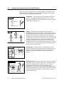
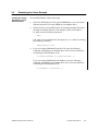
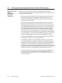
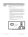
1. Develop a perspective for the process. Examine the
process in its entirety and understand the equipment
involved. View the process as a system, and understand the
role of all the major processing components (such as reactors,
distillation columns, weighing systems, mixers, packaging
systems, etc.). Identify equipment that is, or may become, a
shared resource. For example, a weighing system can be
shared by several mixers.
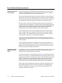
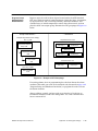
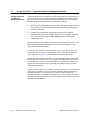
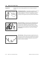
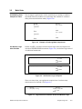
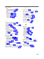
1. Perspective
I need to wash my clothes...
2. Process
Wash
Dry
Determine whether or not you can follow a distributed
approach or you need to use a single controller. If a single
control node approach is followed, address the problem of
capacity. What happens if the solution grows to exceed the
capacity of the controller? Will the solution be distributed
easily to multiple control nodes, or will a major effort be
required? Determine if a potential for future expansion exists.
Consider the possibility that the products made in the process
will change over time to include new or expanded product
lines.
All the above considerations should be addressed in the initial
structuring of the problem. Planning for expansion and
growth in the initial design leads to a flexible, expandable and
often more understandable design solution.
2. Do a top-down analysis. Break a system down into a
hierarchical set of functional subsystems. Control strategies
such as temperature control or pressure control are at the
lower levels in the hierarchy. The goals are at the highest
levels: “The requirement is to wash and dry 220-pound loads
of clothes each week, in five eight-hour shifts”.
1-2
Approach to APT Program Design
SIMATIC APT Applications Manual
Starting with the requirements, your process-design team
develops a physical and operational solution to the problem.
The process-automation engineer puts a control solution in
place to enable the system to achieve the stated process
objective. The automation engineer needs to do a top-down
analysis of the process from the viewpoint of process
automation.
In this phase your design team is attempting to understand
and develop a systems view of the process. A top-down
analysis looks at the process and attempts to answer these
questions first: (1) What are the major process steps involved
in producing a product or family of products? (2) What role
does the process equipment play?
After the major process steps are identified, analyze each of
the major equipment areas and break them down into the
essential processing steps involved. Next break down each
process step into its components. Finally, analyze the various
components of each process step and look for possible further
sub-division.
In this step, focus on the tasks that you need to do. Do not be
overly concerned with the details of how to do them.
Wash System
3. Do a bottom-up implementation. This is the step in which
you address the details. Bottom-up implementation is the
process of developing the code for the functional subsystems
identified in the top-down analysis phase, starting at the
lowest level in the hierarchy: the I/O subsystem.
These are the actual programming and configuration steps
involved in program development. These tasks range from
assigning the symbolic names to equipment to configuring the
operator interface and merging all aspects of the design
control solution. Develop the program incrementally, and test
it thoroughly at each stage of development.
SIMATIC APT Applications Manual
Approach to APT Program Design
1-3
1.2
Develop a Perspective for the Overall Process
When you develop a perspective of a control problem, you develop a clear
understanding of the process and its operation. This phase of the design
process includes the following considerations.
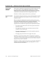
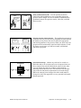
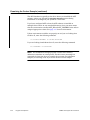
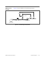
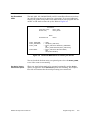
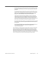
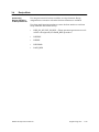
Information. Collect all the relevant information that you
need for a thorough understanding of the project, such as
batch logs, P&IDs, functional specifications, operator station
requirements, I/O lists, etc.
Information
Need:
Water in
Water out (drain)
Power
Gas in
Soap
Washing machine
People
Operator
Maintenance
Process Area
Kitchen
DR
Engineer
BR
Process area. Be certain that you know the area of the
factory for which you are planning a control design. Are you
working on a plan for the entire factory, or a portion of it?
Exactly what are the boundaries to your portion of the
process?
Water heater
Garage
Utility
Washer
BR
Dryer
LR
Bath
Equipment areas. Identify the major areas to be included in
the design. As you determine these areas: weighing systems,
blenders, packaging systems, boilers, etc., you are also
partitioning the process into more manageable units.
Equipment areas represent major processing equipment, not
operational tasks such as Clean-in-Place (CIP). The CIP often
includes multiple equipment areas and should be viewed as
an operational mode.
Equipment Area
Dryer unit
1-4
People. Get all the interested parties involved in the
planning stages: the project engineer, representatives from
management, testing personnel, the operator station graphics
designers. You also need to include the process operators.
These people are the final customers, the ones who need to be
satisfied in order for the process control to run smoothly after
startup. Understand that the people most affected by the
solution (Operations) are the ones who are often the most
unwilling to get involved at this stage. However, for a process
retrofit these are the people with the most knowledge about
how the process actually runs.
Washer unit
Approach to APT Program Design
SIMATIC APT Applications Manual
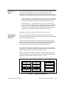
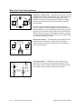
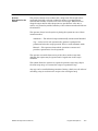
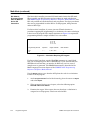
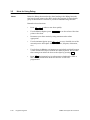
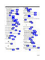
Goals. Identify the goals of the control system.
Goals
You want to design an efficient and effective means of
producing a product.
Manual draining not
required
The process needs to produce a variety of products.
Push-button operation
Automated transfer
to dryer
The design solution must be flexible.
The operator must be able to advance to the next process
step easily.
The operator must be able to abort a batch.
Clean clothes in less
than 1 hour
Model
Add water/soap
Clothes in
Clothes out
Agitate
Spin
Model. Develop and maintain an internal operations
oriented model of the system. Be able to state in simple
language what the system is supposed to do from the
viewpoint of process operation. If you are unable to explain it
easily to another person, you might ask yourself if you really
understand it. Keep in mind the next two steps, top-down
analysis and bottom-up implementation.
Drain
SIMATIC APT Applications Manual
Approach to APT Program Design
1-5
1.3
Do a Top-Down Analysis
At this stage of process control development, you are concerned mostly with
a system view of the process. However, be able to change your focus readily
from the system view to a more detailed view so that you can anticipate and
avoid as many problems as possible.
A design engineer who designs physical process equipment for a plant must
subdivide the facility into functional units, such as mixers or reactors. Each
unit is designed as an independent entity, but with an underlying
consideration for the process as a whole.
As a control engineer, you can use the same tactic when designing the
solution to a process control problem. You can follow a structured, modular
approach by dividing a large control design problem into smaller, more
manageable sub-systems. You design each sub-system independently,
keeping in mind the needs of the system as a whole, and then integrate the
separate results to provide the total design solution.
A systematic procedure that has worked well for Siemens Energy &
Automation engineers who have designed and developed process controls
includes the elements described below.
Consider the Whole
Problem, Then
Subdivide
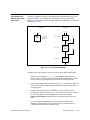
Partition the process into units. Try to divide the process along lines that
represent the functional organization of the physical plant. Then plan to
dedicate one independent section of the application program to each
equipment area. When you partition a system, you are promoting
understanding as well as allowing for expansion.
Always think in terms of function when you choose the partitions. Do not
allow the physical size of the equipment, or its representation on the P&ID,
influence your decisions about partitioning. For example, a piece of
equipment may be so complicated that it is drawn on a single sheet of the
P&ID. This does not necessarily mean that you dedicate an APT unit to
control that equipment. It may functionally belong within another unit.
In the event that the equipment serves as an independent supplier to
several other units, function may dictate that you control this equipment
through its own independent APT unit.
1-6
Approach to APT Program Design
SIMATIC APT Applications Manual
You can improve the organization of your control program by partitioning
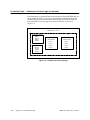
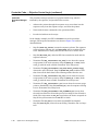
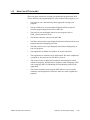
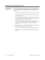
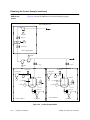
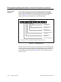
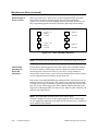
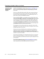
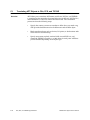
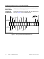
the process by function, not by task. The simple process shown in Figure 1-1
is partitioned by function and by task to show the difference.
Partition by function...
Unit= washing machine
Functions= clothes in
add soap
add water
agitate
drain
Figure 1-1
...not by task.
Unit=
Function=
Unit=
Function =
Unit=
Function=
Unit=
Function=
Unit=
Function=
clothes
put in washing machine
soap
add to washing machine
water
add to washing machine
washing machine
agitate clothes
drain
release water from
washing machine
Partitioning by Function or by Task
Identify interconnectivity among the equipment areas. Within each
partition, note which pieces of equipment are to be shared by different
areas. These items are shared resources and are termed global because
access to them is required in other equipment areas, beyond the immediate
equipment area.
Improper or task-oriented partitioning results in the incorrect inclusion of
many global objects in the system. A common mistake is to make all I/O and
devices global due to uncertainty about which objects are needed by a unit.
This approach results in a system that is less maintainable and expandable.
Consider this: It is easy to move the small number of objects that are truly
global but mis-identified as local. It is more difficult and time-consuming to
move the massive number of truly local variables from global to local
equipment areas.
SIMATIC APT Applications Manual
Approach to APT Program Design
1-7
Do a Top-Down Analysis (continued)
Determine What the
Process Does
Ascertain the upper-level tasks that the process must do. Do not be overly
concerned with the details or how they need to be handled. For example,
consider the equipment functions in a laundry room.
Two operations comprise the process of washing clothes: a wash operation
and a rinse operation. The following phases are common to both operations:
fill, agitate, drain, and spin. The four phases execute in both the wash and
rinse operations. The add soap phase is unique to the wash operation.
You also need to consider operations other than just the wash and rinse
operations. Will the system have to handle delicate clothes differently from
normal loads of clothes? Will permanent press cycles be included? Will the
system handle large, medium, small and extra-small loads? All these
considerations can affect the complexity of the control solution.
The wash operation consists of the following steps: fill, add soap, agitate,
drain, and spin. The rinse operation consists of these steps: fill, agitate,
drain, and spin. The primary differences among process cycles consist of
cycle duration, water levels, and strength of agitation.
A well-planned design differentiates the common process steps from the
unique ones. The common process steps are the building blocks for the total
control solution.
A poorly-planned design treats each phase in each operational mode as
unique. This design approach requires more coding and debug effort. Also,
problems and errors typically have to be corrected in more than one place.
This leads to potential long-term problems.
Determine How the
Process Is To Be
Done
At this stage you want to determine the high-level requirements of the tasks
identified in the previous step. The analysis at this stage is intended to
determine the essential elements of the task.
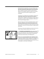
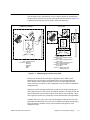
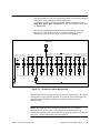
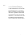
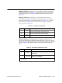
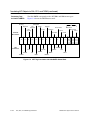
Consider the laundry room example again (Figure 1-2). The fill phase adds
water to the tank up to a predetermined level. The add soap phase meters a
predetermined quantity of soap into the washer. The agitate phase runs the
washer’s agitator for a predetermined length of time. The drain phase
pumps water from the washer. The spin phase runs the spin motor and
injects water into the system during the initial phase of the spin phase.
Each of the previous statements represents a high-level description of the
task without specific details as to what is involved in accomplishing the
task. For each phase, you need to specify functional requirements. For
example, consider the fill phase.
1-8
Approach to APT Program Design
SIMATIC APT Applications Manual
First, determine whether the system will provide a single level, several
levels, or a continuous range of level settings. For a flexible system you may
provide the operator a switch setting for selecting high, medium, low, and
extra-low water levels. This switch setting will be used to determine the
level setpoint for the fill phase. At this stage, however, the only requirement
to consider is whether one or multiple level settings is required.
The temperature of the water in the washer will also be determined by the
fill phase. A common washer design includes a simple solenoid valve for hot
water and one for cold water. In this system, the fill phase will manipulate
the hot and cold water valve to provide both level and temperature control.
The essence of the fill phase is to open the correct combination of water
valves and wait for the level to reach the specified setpoint. When the level
has been achieved, the water valves shut down automatically.
You should analyze each of the other phases similarly.
Fill
Add soap
Drain
Figure 1-2
SIMATIC APT Applications Manual
Agitate
Spin
Determine the Process Tasks
Approach to APT Program Design
1-9
Do a Top-Down Analysis (continued)
Determine Control
Needs
Identify the kinds of continuous control needed, and which safety interlocks
are required. Examples of continuous control include temperature control or
a mass totalizer in a batch reactor. An example of an interlock is a provision
for shutting down the water valves if the tank is full. Another interlock
could stop the spin motor if the washer lid is open.
Define what sequential procedures need to be used in conjunction with the
continuous control. For example, the mass totalizer would be used in the fill
phase of a chemical reactor.
Example: Mental
Exercise for
Top-Down Analysis
1-10
In order to develop a working internal model of the system, consider the
following example. The objective is to assign to yourself the task of
task-master/manager and to delegate all the other tasks. The example is
built around the washer example, and the task-master/manager will be the
master washer. Keep in mind the following considerations.
Suppose that you had a large number of people whom you could ask to
run your process (Figure 1-3). You can employ as many as you like;
however, they are not free. They must be paid, which means there is a
cost to using them in your process. Also consider that a diverse mixture
of skills and abilities is available for you to utilize. Some of the people
are good supervisors and coordinators; others perform detailed tasks
well. Each skill level has a certain cost. Take care to match the skill
level to the task.
Consider the laundry room example again. The washing machine has
valves and motors that need to be controlled and monitored. Control of
a valve is a mundane and rote task, but one which requires attention to
detail and obedience. The task of master washer, on the other hand,
requires the ability to work with others and to coordinate their
activities. Skill with detailed tasks is less important. You are wasting
valuable resources when you select a master washer to handle valve
control, or select a valve controller to do wash coordination.
Approach to APT Program Design
SIMATIC APT Applications Manual
An efficient, cost-effective and understandable organization designed to
execute the task of washing clothes consists of valve/motor controllers, a
level controller, a temperature controller, a tank filler, an agitator, a drainer,
a spinner, a soap dispenser, and a master washer who coordinates the total
wash activity. A safety team, which ensures the safety of the overall
operation, is also needed to work in conjunction with the wash team. The
safety team has the passive role of monitoring conditions until a fault occurs
that demands immediate action. When called to action, the safety team
works primarily with the valve/motor controllers to ensure the safe
shutdown of the washer system.
This exercise is simplistic, but may give you ideas to consider as you study
the control design for your process. It can help you identify the tasks that
make up a process, determine the process partitions, and to develop a feel
for what the process is supposed to do.
Master washer
Add water/soap supervisor
Mix supervisor
Drain water supervisor
Soap in
Water on/off
Clothes in/out
Drain water
Figure 1-3
SIMATIC APT Applications Manual
Agitate
Example of Control Determination
Approach to APT Program Design
1-11
1.4
Plan the Bottom-Up Implementation
Use a Layered
Approach
The bottom-up implementation consists of doing all the related tasks
concerned with designing and creating the application program. Approach
the design as a series of levels with a number of layers within each level.
Level and layer are defined as follows: A level represents the degree of
automation for a process, ranging from operator control to full automatic
control. A layer represents the tasks that you have to complete in order to
bring a process to a certain level of control.
At Level 1 control, the degree of automation is such
that the operator can manipulate the control system easily.
Safety protection logic has been incorporated into the process,
and continuous control logic is in place. At the operator
station, the operator must manually operate devices, modify
loop modes and change set points in order to run the process.
Level 1
On/Off
On/Off
The system is ready for loop testing, PID tuning, and physical
equipment testing. You need to verify that an operator can
successfully monitor and control the process from the operator
station, through the controller, to the field equipment.
On/Off
In the laundry example, you have a washing machine that
requires considerable manual control. The water valves are
connected but you open and close them manually. The agitator
can operate, but you must start it and stop it. You must also
start and stop the drain pump and spin motors.
Level 2 A process at Level 2 has operational goals imposed on
a Level 1 process with a simple operator interface structure.
Your prerequisites for the development of a process to Level 2
include a sequence list of defined procedures, an execution
order for the procedure, and a formula recipe list. As control
development proceeds, the process advances through three
states: Procedural, Structural, and Objective Control.
agitate
fill
drain
Procedural Control. Basic control procedures are defined.
You concentrate on developing the set of operational
procedures that perform specific functions when activated by
a higher level of control. Procedures include tasks such as Fill
Tank, Agitate, Drain Tank, etc. You have two priorities for
procedural control: the procedure does the assigned tasks
correctly, and the procedure operates independently and
potentially in parallel with all other procedures.
In the laundry example, your goal is to design a procedure
which responds to a discrete signal, such as a pushbutton, to
begin operation. When this procedure has finished, it turns on
another discrete signal. For example, the Fill procedure
begins when a pushbutton is pressed, and illuminates a lamp
when filling is finished.
1-12
Approach to APT Program Design
SIMATIC APT Applications Manual
Structural Control. You plan the flexibility for the system
structure. A very rigid system has a fixed and definite
execution pattern. A flexible system has an open data-driven
pattern. For this reason, a flexible data-driven design is
recommended. Consider this: you can build a rigid system
from a data-driven pattern, but you cannot build a flexible
system that is based on a rigid structure.
fill
agitate
drain
In the laundry example, each of the operational phases is
independent and can be executed at any time with a
pushbutton when procedural and structural controls are in
place. Interlocks are in place to prevent certain phases from
executing simultaneously, such as Fill Tank and Drain Tank.
cold
hot
warm
fill
agitate
drain
wool
knits
cottons
Objective Control. You impose a data-driven execution
pattern upon structural control. The process operation
becomes essentially automatic, subject to operator
intervention, and has the full flexibility offered by many
recipes.
In the laundry example, you select the wash cycle that drives
the various procedures, Fill, Agitate, etc. You can select from
one or more wash cycles, start the washing machine, and
leave, knowing that when you return the clothes will be
washed.
Good morning, Ralph! Please insert
your laundry and I will be happy to
process it for you. Thank you!
SIMATIC APT Applications Manual
Level 3 A process at Level 3 control has been developed and
improved thoroughly. All necessary and desired refinements,
e.g., report design, operator help screens, etc. have been
added. Level 3 control may be an ongoing process that extends
beyond initial commissioning.
Approach to APT Program Design
1-13
Plan the Bottom-Up Implementation (continued)
There is a set of related tasks that, logically, you need to do first.
This set of related tasks comprise a layer in the level of control defined
above. Each task in the layer represents a degree of accomplishment. When
you complete the first layer of tasks, you proceed to subsequent logical
groups of tasks, or layers, until the process control design is finished.
Layers.
Figure 1-4 illustrates the levels and layers that make up the bottom-up
implementation. Layers of tasks represent more and more structure and
increasing dependency upon lower layers of design to function correctly. The
addition of each layer adds more automatic controls and, consequently, less
reliance on an operator to handle control functions.
Figure 1-4 shows how the levels of control change as you proceed in the
development of your program. Note, however, that as you climb the stairs
that represent each layer of tasks, your progress is not strictly linear.
Typically, you must do some backtracking, and translate tags again, or
program some more continuous control after having worked on structural
control, for example.
As you work on each layer of tasks, never lose sight of the top-down goals
and the associated internal model described in Section 1.2. Continue to
partition your work. Divide a problem into small sub-problems, or modules,
that can be addressed independently and systematically. This will enable
you to minimize the number of complex issues to be dealt with at any point
in the design cycle.
Sections 1.5--1.13 of this chapter describe the tasks in detail and give you
some suggestions about how to do them. You can create any application
program by following the order in which they are presented.
1-14
Approach to APT Program Design
SIMATIC APT Applications Manual
Level 3 Control
Level 2 Control
Level 1 Control
Program enhancements (Sec. 1.13)
Layers 9+
Program objective control (Sec. 1.12)
Layer 8
Program structural control (Sec. 1.11)
Layer 7
Program procedural control (Sec. 1.10)
Create data dictionary (Sec. 1.9)
Create recipes & templates (Sec. 1.9)
Layer 6
Create templates for procedural control (Sec. 1.8)
Verify operator station graphics. (Sec. 1.7)
Build operator interface database (Sec. 1.7)
Layer 5
Identify addresses for operator interface database (Sec. 1.7)
Program safety & shutdown interlocks (Sec. 1.6)
Program other alarms (Sec. 1.6)
Program automatic start (Sec. 1.6)
Layer 4
Program other continuous functions (Sec. 1.6)
Program loops and analog alarms (Sec. 1.6)
Define discrete devices (Sec. 1.5)
Layer 3
Configure I/O (Sec. 1.5)
Determine I/O Module Layout (Sec. 1.5)
Select the Controller (Sec. 1.5)
Layer 2
Partition process into units (Sec. 1.5)
Plan testing and simulation (Sec. 1.5)
Select a consistent and meaningful naming convention (Sec. 1.5)
Layer 1
Plan the memory allocation (Sec. 1.5)
Figure 1-4
SIMATIC APT Applications Manual
Tasks Comprising the Bottom-Up Implementation
Approach to APT Program Design
1-15
Plan the Bottom-Up Implementation (continued)
Study the Example
Program
WASH_DEM for
Series 505
Controllers
The example program WASH_DEM illustrates the concepts that are
emphasized in this chapter. If you load it on your system, you can follow
along with the control strategy. To install WASH_DEM follow these steps.
1.
Insert the APT software CD in your CD-ROM drive; or, if you created
diskettes from the CD, insert DISK8 in your diskette drive.
2.
Ensure that the current DOS “path” environment includes the path to
the APT executables directory. For example, if APT is installed at
D:\APT, enter the following command:
PATH
If D:\APT is not included in the list output by PATH, add it by entering
the following command:
PATH=%PATH%;D:\APT
3.
If you are loading the example program from the CD, enter the
following command, substituting your diskette drive for E, and your
disk drive containing the APT database for D:
E:\DISK8\LOADDEMO
E:\DISK8\WASH_DEM
D:
If you are loading from diskette, enter the following command,
substituting your diskette drive for A, and your disk drive containing
the APT database for D:
A:\LOADDEMO
A:\WASH_DEM
D:
The APT database is typically on the drive where you installed the APT
software, unless you selected the Configure Directories option during
installation or reconfigured your system at a later time.
1-16
Approach to APT Program Design
SIMATIC APT Applications Manual
If you have configured APT so that the APT software is installed on
multiple drives and/or in non-standard directories, then you must ensure
that the environment variables APT_DB and APT_COMMON exist and are
assigned appropriate values. APT_DB specifies the path to the APT
database and APT_COMMON specifies the path to the directories FORMS,
LIB505, LIBMC5, and TEXT. If these environment variables are not set and
you know the correct values, you can set them.
For instance, consider that the APT executables are in D:\APT, the
database is in C:\DATABASE, and the TEXT directory is in E:\APT. As
above, ensure that the PATH includes D:\APT, and then set the other
environment variables by entering the following commands:
SET APT_DB=C:\DATABASE
SET APT_COMMON=E:\APT
If you are loading from CD drive G, enter the following command:
G:\DISK8\LOADDEMO
G:\DISK8\WASH_DEM
If you are loading from diskette drive B, enter the following command:
B:\LOADDEMO
B:\WASH_DEM
To install the other example programs, substitute the program names
(APT_SIM, FOOD545N, HX_DEMO, or WASH_S5) for WASH_DEM.
SIMATIC APT Applications Manual
Approach to APT Program Design
1-17
Plan the Bottom-Up Implementation (continued)
Coordinating With
Operator Interface
Design
On the left side of Figure 1-5 you can see a list of the typical tasks involved
in creating a process control program. The right side includes the tasks
involved in creating a corresponding operator interface. Ideally, you do these
two sets of tasks in parallel.
Develop a Perspective
Do a Top-Down Analysis
Control Software Design
Execute Bottom-Up Implementation
Level 1 Tasks
Do These Tasks in Parallel
Plan Memory Allocation
Operator Interface Design
Design Process Graphics
Select Naming Convention
Create Dynamic
Symbols
Plan Testing and Simulation
Create Shapes
Partition Process into Units
Create Animation for
Shapes
Select the Controller
Create Forms
Determine I/O Module Layout
Place Graphics on
Screen
Configure I/O
Define Discrete Devices
Associate Tag Names
with Dynamic Symbols
Do These Tasks in Parallel
Design Continuous Control
Program Loops & Analog Alarms
Create the
Simulation
Algorithms
(Optional)
Program Other Continuous Functions
Program Automatic Start
Program Other Alarms
Program Safety and
Shutdown Interlocks
Identify Addresses for Operator Interface Database
Continued on Next Page
Figure 1-5
1-18
Approach to APT Program Design
Steps of Designing Process Control
SIMATIC APT Applications Manual
Bottom-Up Implementation
Continued from Previous Page
Build Operator Interface Database
Verify Operator Station Graphics
Level 2 Tasks
Control Software Design
Do These Tasks in Parallel
Create Templates for Procedural Control SFCs
Operator Interface Design
Refine Graphics
Create Recipes
Animate Words, Symbols
Create Templates/Recipes for
Setpoints, Alarm Values, Loops, etc.
Create Help Screens
Create Data Dictionary
Create Status Pages
Program Procedural Control
(Fill Out Templates for Procedural Control SFCs)
Program Structural Control
(Create Procedure Activator SFC)
Program Objective Control
Create Sequence Recipe
Create Main SFC
Create Sequence Array
Create Procedure Manager SFC
Level 3 Tasks
Continuous Improvements
Figure 1-5
SIMATIC APT Applications Manual
Steps of Designing Process Control (continued)
Approach to APT Program Design
1-19
1.5
Create the Code — First Steps
In Section 1.4, you can find the list the tasks that comprise the bottom-up
implementation. Figure 1-5 shows you the order for completing the tasks
and also illustrates how the process design engineer can coordinate efforts
with the operator interface design engineer. This section describes, in detail,
what you need to do when you execute each task of the process control
design.
Plan Memory
Allocation
If you do not intend to monitor your process with an OSx operator interface,
you must decide early in your process control design which controller
memory locations are to be reserved for your operator interface. APT can be
programmed to avoid these locations when you compile the program.
Select Naming
Convention
Choose names for your I/O and devices that are meaningful so that you can
easily identify their functions. If you intend to copy these objects for use
elsewhere in the program, remember that names must be unique, as well as
meaningful. Initially, try to choose names that are less than nine characters
in length. Choose names that are easily transferred to the operator interface
and avoid creating a cross-reference to which you must continually refer.
Plan Testing and
Simulation
Begin planning your code tests early to anticipate problems that may occur.
The simulation program is an optional task, but is recommended as an
excellent way to test your code before process startup. The simulation allows
you to concentrate on debugging the program without being concerned with
the logistics of doing the tests. A software simulation program allows you to
test your process control program by simulating real-time conditions. Since
software routines can be stored as files, you can run them over and over
very quickly and simply note the results.
APT includes a utility program called MAITT that simplifies the task of
repeatable logic testing. You can design the test routines to generate reports
that are stored or printed. With MAITT it is very easy to test the control
system response to variable inputs. When you develop new code, you can
easily test the existing code to verify that it still executes correctly.
Partition the
Process into Units
1-20
Examine the partitions that you defined when you sub-divided the process
during the top-down analysis. Each partition represents a portion of the
functional organization of the physical plant. Dedicate one APT unit to each
partition and begin adding the units to the APT hierarchy. Determine which
units can be copied and used elsewhere in the program. Define only the
original unit.
Approach to APT Program Design
SIMATIC APT Applications Manual
Select Controller
The controller that you use must be able to support the number of I/O points
that you are planning for your process. Remember that the 560/560T and
565/565T/565P controllers support up to eight I/O channels and as many as
8192 I/O points. The 555 and the 575 support up to 8192 I/O points in one
I/O channel. The 545 supports 2048 I/O points in one I/O channel, and the
545L supports 1024 I/O points in the local base. The S5 928B, 948, and
948R CPUs support 2048 inputs and outputs with process image, and 384
analog inputs and outputs through the periphery.
Determine I/O
Module Layout
Determine the kinds and numbers of modules that you need. Plan their
location carefully. Allow for expansion. If you try to reduce costs by using
fewer modules and bases, you may ultimately increase the expense of
expanding the system. When you use APT to develop the program,
remember that for a Series 505 controller, the module table determines the
address space, but the object belongs to the I/O Table. This allows you to
test code even when the I/O configuration is not yet known. When you
develop a program for an S5 controller, you determine the addresses by
setting the dipswitches on the I/O modules. You then use the I/O Editor to
enter these addresses into the I/O Table. For an S5 controller, you can test
code without the I/O connected by selecting the image register in the I/O
Table.
Configure I/O
Enter the I/O data into the I/O Symbolic Name Table: addresses, alarm
limits, scaling data, offset information, etc. Take the time to document the
I/O by including descriptive data and engineering units. This saves time
and avoids confusion for other people who need to understand your system.
When you make changes in the table, remember to validate the I/O after
you exit the I/O Table.
Define Discrete
Devices
Enter the device data into the Device Definition Table: type, commands,
alarm times, limit switches, etc. Take the time to document the devices by
including the descriptive data.
A Device Definition Table is available at both the Program Level and at the
Unit Level. Devices defined at the Program Level can be referenced in any
unit in that program. Devices defined at the Unit Level can be referenced
only within that unit. When you make changes in the table, remember to
validate the devices after you exit the Device Table.
Consider compiling the program and downloading it to the controller at this
point. Do this to verify that devices are connected to the correct I/O points
and that the alarm times are correct. However, before you can compile,
remember that the field I/O associated with the APT device must be defined
in the Module Definition Table and in the I/O Table for analog inputs.
SIMATIC APT Applications Manual
Approach to APT Program Design
1-21
1.6
Create the Code — Continuous Control Logic
At this stage of the process design, you begin writing the actual program
code. Try to use continuous control logic to handle as many functions of your
process as possible, and allow the sequential control code to do the
scheduling for these functions. For this reason, it is best to begin work on
the continuous control first.
As you design the continuous control code, determine the various control
strategies and group them appropriately. The categories for the groups
depend upon your own process and what is most convenient, not only for the
current programmers, but also for those who must maintain and update the
program. Use different Continuous Function Charts (CFCs) for the different
functional control strategies, as shown in Table 1-1.
Table 1-1
CFCs Reflect Control Strategies
Function
Program the
Simulation Math
1-22
CFC Name
Temperature Control
T_ctrl
Level Control
Lev_ctrl
Pressure Alarms
Prs_alrm
Agitator Startup
Agi_strt
Safety Interlocks
Interlck
Place Devices in Auto Mode
Auto_dev
You can program the math for the optional simulation as a continuously
operating function. The simulation math is not necessarily the first code
that you need to write, but you can develop it in parallel with the other
continuous control logic. Place the simulation math in one or more math
Continuous Function Blocks (CFBs), located in a CFC dedicated to program
testing.
Approach to APT Program Design
SIMATIC APT Applications Manual
Program Loops,
Analog Alarms,
On/Off Control
Begin to write the code for those objects located under the APT Standard
CFC icon. Think in terms of control strategies. Group the loops, for example,
by logical function, and avoid being bound by artificial boundaries. Two
cascaded loops, in which temperature control drives flow control, are best
placed in their own unique group. Examine the CFC groupings in Figure 1-6
below.
Group CFBs like this ...
... not like this.
Ramped Temperature Control Strategy
Temperature Control CFC
CFC: T_CTRL
Heat Exchanger
Temperature Setpoint
Ramp CFB
Temperature Control
CFB Loop 1
Temperature Control
CFB Loop 2
Temperature Control
CFB Loop 3
Heat Exchanger
Temperature Control
CFB
Temperature Control
CFB Loop 4
Heat Exchanger
Flow Control
CFB
Temperature Control
CFB Loop 5
Pressure Control CFC
Pressure Control
CFB Loop 1
Pressure Control
CFB Loop 2
CFC: LEV_ALARM
Tank Level Alarm
CFB
Figure 1-6
Example of CFC Groupings
For analog alarms, focus on programming the code that detects the alarm
condition. Wait until you work on the interlock code, discussed on page 1-25
“Program Safety and Shutdown Interlocks,” to program the code to correct
the alarm condition.
Always validate, compile, and test code as you develop it. Do this in an
incremental fashion to reduce the debug effort. Use a test controller that
has no connected I/O.
SIMATIC APT Applications Manual
Approach to APT Program Design
1-23
Create the Code — Continuous Control Logic (continued)
Program Other
Continuous
Functions
Other forms of continuously operating functions include totalizers and code
for a specific module, such as PEERLINK communications, Industrial
Ethernet peer services, HSPI control logic, flashing lamps, etc. Focus on
solving the problem, not on analyzing the flow of events, because the path
can become very convoluted as you try to anticipate future events.
Remember to validate, compile, and test code as you develop it.
Program Automatic
Start
The automatic startup for some devices, loops, and analog alarms is another
function that is frequently better handled as a form of continuous, versus
sequential, control.
When you define the conditions that control an operation, then you can
create a continuous control strategy, based on those conditions, that handle
the operation. Remember that the way you approach the problem
determines how you find the solution. Think continuous control, not
sequential control. Consider these typical process requirements for objects.
The agitator starts whenever the water level is greater than 20% for
more than a minute.
The temperature controller is set to automatic whenever the flow
controller is in the cascade mode.
The supply solenoid opens whenever the flow controller is placed in
automatic or cascade modes.
The supply pump starts whenever the supply valve opens.
Remember to use the flag variables, which are objects that are similar to
devices, but which have only two states: on or off. The flag variable provides
a useful way to control objects through math statements. Objects respond to
flags just as they would to commands.
Remember to validate, compile and test code as you develop it. Remember to
do this in an incremental fashion to reduce the debug effort. Use a test
controller that has no connected I/O.
1-24
Approach to APT Program Design
SIMATIC APT Applications Manual
Program Other
Alarms
Other alarm conditions that you want to monitor may be too simple to be
programmed as analog alarms, or the analog alarm function is not
appropriate. These alarms typically have only one or two conditions that set
off a signal to an interlock to handle the problem. Consider these examples.
Monitor tank level — A declared boolean value is true when the level is
greater than one value or less than another. When the level is outside
the range, the boolean value becomes true and triggers interlocks.
Monitor flow rate — A declared boolean value is true when the flow
rate is less than a certain value for a specified period of time. When the
flow rate is too low, a timer begins to time down. The boolean value
becomes true and triggers interlocks when the timer times out. Note
that the timer does not time down unless the flow rate is low.
Remember to validate, compile and test code as you develop it.
Program Safety
and Shutdown
Interlocks
The code that handles interlocks and other safety-related concerns is
another example of logic that is best programmed in the form of continuous,
rather than sequential, control.
As with loops and analog alarms, you need to group interlocks by logical
function. It can be very difficult to determine the reason for the failure of a
device, for example, when you must search through all the program
interlocks for the one that has stopped operation of that device.
It is also best to place all the interlock code for an object in one location of
the program. It is much less difficult to troubleshoot an interlocked object
when the interlock code is not in several different places.
Dedicate one CFC in each unit to contain the interlock code for that unit.
Consider dedicating one (interlock) CFB to handle interlock operations for
each device and each CFB, as shown in Figure 1-7 below.
Interlock CFC — Unit 1
Valve 1 Interlock
CFB
Valve 2 Interlock
CFB
Valve 3 Interlock
CFB
Valve 4 Interlock
CFB
Pump 1 Interlock
CFB
Pump 2 Interlock
CFB
Figure 1-7
SIMATIC APT Applications Manual
Temperature Loop 1
Interlock CFB
Temperature Loop 2
Interlock CFB
Temperature Loop 3
Interlock CFB
Example Interlock Blocks
Approach to APT Program Design
1-25
Create the Code — Continuous Control Logic (continued)
Note that there is a practical limit to the number of interlock CFBs that you
group within one CFC. If you have a large number of interlocks in a unit,
consider placing all device interlocks of one device type into one CFB, all
loop interlocks for one loop type into another CFB, etc., as shown in
Figure 1-8.
Interlock CFC — Unit 1
Valve Interlock CFB
Valve 1
Valve 2
Valve 3
Valve 4
Temperature Loop
Interlock CFB
Loop 1
Loop 1
Loop 2
Loop 2
Pump Interlock CFB
Loop 3
Loop 3
Pump 1
Pump 2
Pump 3
Pump 4
Loop 4
Loop 4
Figure 1-8
1-26
Pressure Loop
Interlock CFB
Approach to APT Program Design
Example Interlock Groupings
SIMATIC APT Applications Manual
Every APT device and CFB has a .NRDY extension. Use it in your interlock
code as an indication of whether the device or CFB is ready for operation.
Table 1-2 lists some interlock conditions and shows how the .NRDY extension
can be used in the program code.
Table 1-2
Object to Go to
Fail-Safe State
Uses for the .NRDY Extension
Condition
Code
Supply pump
The supply valve is
not open.
SP.NRDY : = NOT(SV.OPND);
Flow controller in
manual with zero
output.
The temperature is
too high.
FC.NRDY : = TC.INHHA;
IF (EDGE (FC.NRDY)) THEN
FC.OUT : = 0.0;
ENDIF;
Remember to validate, compile, and test code as you develop it. Remember
to do this in an incremental fashion to reduce the debug effort. Use a test
controller that has no connected I/O.
SIMATIC APT Applications Manual
Approach to APT Program Design
1-27
1.7
Create the Code — Operator Interface Addresses/Graphics
Identify Addresses
for Operator
Interface Database
Follow the steps below to identify the APT objects that are to be referenced
by the operator interface. This procedure was designed for an OSx system,
but you can use it for any operator interface. Both steps can be done from
the APT environment by selecting the appropriate options.
1.
Mark tags for translation. In this step you select objects (tags) that are
to be used by the operator interface and that must have unchanging
controller addresses.
2.
Compile the program with the Yes option selected in the Build
Translate File field of the Compile Control File. If controller addresses
are to remain fixed, select the No or Append option in subsequent
compile operations.
This step builds the executable code used by the controller and creates a file
that contains controller addresses that are fixed (unchanging) for each
object that you marked in Step 1.
If your operator interface is an OSx system, you can use the file that was
created in step 2 to build the OSx database. This is an automated process
and is described on page 1-29, “Build Operator Interface Database.”
If your operator interface is not OSx, you can still mark objects and fix their
addresses in the controller when you compile the APT program. The next
step, building the operator interface database, is a manual procedure. You
can use the file created in step 2 to identify the addresses that you must
enter into the database.
If your operator interface is not OSx (or even if it is OSx), you do not have to
mark tags for translation. You can reserve controller memory and assign
selected addresses to the objects that you want to monitor with your
operator interface. If you choose this method, you must include code in the
controller program that moves the necessary data into the address that the
operator interface monitors.
1-28
Approach to APT Program Design
SIMATIC APT Applications Manual
Build Operator
Station Database
Enter the controller addresses for objects that are monitored by the operator
interface into the operator interface database. Note that these addresses
must remain unchanged in the controller program if the operator interface
is to access data during run time. If you alter an address for an object, you
need to make the appropriate change in the operator interface database.
You can use the APT Translate Tags utility to place the object’s controller
address into a database that is compatible with OSx. This is an automated
procedure that also places other data into the database, including the
object’s name and description.
This is a manual procedure when your operator interface is not OSx. You
must enter the object’s controller address into the operator interface
database. Consider writing a short program that can read the ASCII file
generated by APT (install.tag) when you compile the program and then write
the object’s address to your operator interface database.
Verify Operator
Station Graphics
Download the program and connect the operator interface to the controller.
Verify that the operator interface graphics are reflecting the operation of the
controller program correctly. Do the icons change colors as they should? Are
the correct messages being displayed? Can you use the operator interface to
interact with the controller program, i.e., can you open a valve or turn on a
motor?
You can use the APT Debug utility or MAITT, along with the operator
interface, to do these tests.
Finish Level 1
Tasks
After you verify the operator station graphics, the Level 1 tasks are
completed. Section 1.8 describes the Level 2 tasks.
SIMATIC APT Applications Manual
Approach to APT Program Design
1-29
1.8
Create the Code — Templates for Procedural Control
At this stage of the process design, you start on the Level 2
tasks. The continuous control logic is well defined. Program
code may not be complete, but its development is under way.
It is time to begin work on scheduling the continuously
executing functions. This point in the process design marks
the beginning of the work on the Sequential Function Chart
(SFC) structures.
Procedural Control
agitate
fill
drain
Begin by examining the continuous control strategies that you
have already defined. Refer to your top-down analysis and
determine what the procedures are. These procedures are
handled by the individual SFCs used in a unit. Identify what
the order of execution for these SFCs must be and how they
interact with the continuously executing functions.
Subordinate SFCs
Give the SFCs meaningful names. Choose a naming convention that has
meaning to your process and then use it consistently. In the laundry
example, the subordinate procedures may have names such as Fill,
Add_Soap, Agitate, and so on.
Think in terms of designing only SFC templates at this stage of the process
design. You are laying only the foundation of a design structure. You will be
coming back later in the design process to fill in the details. This means that
you do not want to write complete and fully functional SFCs yet. Each SFC
template must have a defined function, and each SFC must be activated by
a temporary Main SFC, but it need not actually do any useful tasks yet.
However, the program must be able to compile successfully. Figure 1-9
shows SFC templates for the laundry example.
Subordinate SFCs
Fill
Agitate
Start_Fill = True;
On Fill_Done;
Drain
Start_Agit = True;
On Agit_Done;
Start_Fill = False;
Figure 1-9
Start_Drain = True;
On Drain_Done;
Start_Agit = False;
Start_Drain = False;
Example SFC Templates
The final transition of each subordinate SFC in the example waits for the
start command to clear and ensures that the (temporary) Main SFC
determines when the functions run. If the Main SFC waits until the
done flag for an SFC is true and then clears the Start command, then each
subordinate SFC executes only once and resets for another Start command.
1-30
Approach to APT Program Design
SIMATIC APT Applications Manual
Use declaration flags for start flags (Start_Fill, Start_Agit, Start_Drain) and
for done flags (Fill_Done, Agit_Done, Drain_Done).
As you finish creating each SFC template, exit and validate the SFC. Then
continue creating templates until all the initial operational procedures are
defined.
Main SFC
When the individual SFC templates are identified, define an SFC to act as a
procedure activator. This is the Main SFC, and its primary function is to
activate the individual SFCs. The operation is comparable to a subroutine
call in a BASIC program or a procedure in a C program. The subordinate
SFCs, once activated, begin to monitor their respective Start commands and
are executed as needed. The subordinate SFCs remain active: active/idle,
active/working, or active/done and waiting.
Design this Main SFC with the knowledge that it may be the Main SFC
only temporarily. As you refine the program and add enhancements, you
may find the need to replace one Main SFC with another. The Main SFC in
the laundry example is named Phases (Figure 1-10).
Main SFC — Procedure Activator
Phases
True
SFC Fill;
SFC Agitate;
SFC Drain;
True
Figure 1-10
Example Procedure Activator SFC
The temporary Main SFC (the procedure activator) has an initial step
followed by a true transition. Next is a parallel construction that contains a
step for each subordinate SFC. Within each of these parallel steps a call to
one of the subordinate SFCs is made. Note that none of the subordinate
SFCs ever terminate; each is in an endless loop. Therefore, the procedure
activator never reaches the exit step.
This approach allows you to test and adjust event scheduling without being
distracted by the details of what the SFCs must do. The development of the
actual SFC program code is discussed in Section 1.10.
SIMATIC APT Applications Manual
Approach to APT Program Design
1-31
1.9
Create the Code — Recipes and Recipe Templates
At this stage of the process design, the program structure is in place. It is
time to return to the procedural control and complete this code. This point
in the process design marks the beginning of the work on recipes and recipe
templates.
APT recipes are multi-functional. Recipes are used to assign meaningful
names to values, define operational setpoints, or to specify the order of
operations. Treat the recipe as a tool that can help provide meaning and
structure to a program.
Recipes are associated with a template that defines the element name, data
type, description, and engineering units for the element. You define the
template at the program content level of the hierarchy. You define values for
the individual recipe elements through the Recipe Usage Table editor.
Build the Template
To create a recipe, begin by defining a template. Try to think of all the
possible setpoints that you may need and include them in your list.
Figure 1-11 shows the setpoints for the laundry example and their
corresponding entries in a template.
Enter setpoints
into the template.
Operational Setpoints
Element
Temperature setpoint #1 Hot/Warm/Cold
Temperature setpoint #2 Hot/Warm/Cold
Temperature setpoint #3 Hot/Warm/Cold
Fill level #1 High/Medium/Low
Fill level #2 High/Medium/Low
Fill level #3 High/Medium/Low
Wash agitate time #1 Average/Extra long
Wash agitate time #2 Average/Extra long
Rinse agitate time #1 Average/Extra long
Rinse agitate time #2 Average/Extra long
Figure 1-11
1-32
Approach to APT Program Design
Tmp_sp1
Tmp_sp2
Tmp_sp3
Fill_lev1
Fill_lev2
Fill_lev3
Wsh_agi_tim1
Wsh_agi_tim2
Rns_agi_tim1
Rns_agi_tim2
Recipe Template
Type Description
I
I
I
I
I
I
I
I
I
I
Temp. SP #1
Temp. SP #2
Temp. SP #3
Fill level #1
Fill level #2
Fill level #3
Wash agitate time #1
Wash agitate time #2
Rinse agitate time #1
Rinse agitate time #2
Eng. Units
Celsius
Celsius
Celsius
Gallons
Gallons
Gallons
Minutes
Minutes
Minutes
Minutes
Example Recipe Template
SIMATIC APT Applications Manual
Build the Recipe
Create a recipe within the main unit of the process, the unit that handles
the primary task(s) of the process. This will be the working recipe, the
recipe that contains the current recipe element values when the process is
active. When you download a recipe during runtime, you will be copying one
of your library recipes into this working recipe.
Assign the working recipe a short name, e.g., WR (for Working Recipe) so
that the element names can be as long as possible. Then enter the value for
each element.
Figure 1-12 shows the setpoint values for the laundry example. The values,
Hot, Warm, Medium, etc., are integer constants that you need to define in
the Declaration Table. This can be done either before or after you enter
them as values in the recipe value fields. Define each one at either the
global or the unit level, and assign it a unique numerical value.
NOTE: APT only accepts text in recipe value fields if the text is the name of
either an integer or a real that is declared as a constant.
Value
Units
Recipe Values
Element Name Description
Hot
Warm
Cold
High
Medium
Low
Average
Ex_long
Average
Ex_long
Celsius
Celsius
Celsius
Gallons
Gallons
Gallons
Minutes
Minutes
Minutes
Minutes
Tmp_sp1
Tmp_sp2
Tmp_sp3
Fill_lev1
Fill_lev2
Fill_lev3
Wsh_agi_tim1
Wsh_agi_tim2
Rns_agi_tim1
Rns_agi_tim2
Figure 1-12
Temp. SP #1
Temp. SP #2
Temp. SP #3
Fill level #1
Fill level #2
Fill level #3
Wash agitate time #1
Wash agitate time #2
Rinse agitate time #1
Rinse agitate time #2
Type
I
I
I
I
I
I
I
I
I
I
Example Recipe
Choose values for names as is appropriate for your program, but always
assign the following values to these loop modes, so that they correspond to
the loop extension .SMODE. (For information about .SMODE, see the
section on PID (Chapter 2) in the SIMATIC APT Programming Reference
(Graphics/Math) Manual.)
In_Automatic — 4
In_Cascade — 6
In_Manual — 2
SIMATIC APT Applications Manual
Approach to APT Program Design
1-33
Create the Code — Recipes and Recipe Templates (continued)
Create Data
Dictionary
Build the Dictionary Template Create a data dictionary as a structured
means of defining meaningful names for use in the program. The recipe and
template are preferable to multiple declaration tables for holding data
dictionary values. Using the recipe and template keeps all the information
in one place, makes it easy to reference, and helps to avoid duplicate entries
that can make troubleshooting difficult. See Figure 1-13.
Process
Names
In_Fill
In_Agitate
In_Drain
In_Rinse
In_Spin
Enter names into
the template.
Element
In_Fill
In_Agitate
In_Drain
In_Rinse
In_Spin
Figure 1-13
1-34
Approach to APT Program Design
Dictionary Recipe Template
Type Description
I
I
I
I
I
Tank is filling
Agitator is running
Tank is draining
Clothes are rinsing
Tank is spinning
Eng. Units
N/A
N/A
N/A
N/A
N/A
Example Data Dictionary Template
SIMATIC APT Applications Manual
Build the Dictionary Recipe Create a program-level recipe named D. Keep
the name short so that anyone who examines the program will focus on the
meaning of the extension and not the recipe name, e.g., D.IN_FILL, D.IN_SPIN.
See Figure 1-14.
Value
Units
Recipe
Element Name
Description
8
16
24
32
40
N/A
N/A
N/A
N/A
N/A
In_Fill
In_Agitate
In_Drain
In_Rinse
In_Spin
Tank is filling
Agitator is running
Tank is draining
Clothes are rinsing
Tank is spinning
Figure 1-14
Type
I
I
I
I
I
Example Data Dictionary Recipe
Keep values unique to avoid confusion. Use multiples of eight if you intend
to use OSx to animate tags that use values that are defined in the data
dictionary.
NOTE: You can designate that your data dictionary be only a data structure
on the recipe usage table form. A data structure does not get the
handshaking code that recipes get, but can be marked for tag translation.
SIMATIC APT Applications Manual
Approach to APT Program Design
1-35
1.10
Create the Code — Procedural Control Logic
Continue your work on sequential control by writing the code to handle
specific procedures. Select one of the SFC templates that you developed for
procedural control and the begin to enter the code that executes the
appropriate tasks. Do this for all the SFC templates. Your priority is to
make sure that each SFC does the intended task, and does it correctly. Be
sure to test your code thoroughly.
In the laundry example, consider an SFC called Fill, which helps coordinate
the fill task for the washing machine. The steps and transitions are shown
in Figure 1-15 and described below.
Step S1 waits for a signal from the procedure activator (called Phases
in the laundry example) that the fill procedure is to begin.
Transition T1 [Strt_fill] becomes true when the start command Strt_fill
is true. An SFC at a higher management level, which you program for
Objective Control (page 1-40), latches on the start command.
Step S2 [Increment fill_s; Fill_level : = wr.fill_sp; Temp_setpt : =
wr.tempt_setpt;] loads setpoints for level and temperature based on
values in the working recipe. S2 also increments a counter to keep
track of the number of times that the Fill SFC is executed. Transition
T2 is always true.
1-36
Step S3 contains no code and waits for the level to reach the selected
level. Water level is controlled in part by a CFB that opens the hot and
cold water valves when a new setpoint is loaded. An interlock CFB is
programmed to shut off the valves by setting the cold_water.NRDY and
hot_water.NRDY bits when the level reaches the setpoint.
Transition T3 [Fill_at_sp] becomes true when the level reaches the level
specified by the setpoint.
Step S4 [On fill_done; Clear stop_fill] turns on a flag to indicate that the
fill task is finished and clears the stop command.
Transition T4 [Not (strt_fill)] waits for the start command Strt_fill to
clear. This path loops back and program flow waits for Strt_fill to
become true again.
Approach to APT Program Design
SIMATIC APT Applications Manual
S1
{Wait for start command}
T1 Strt_fill
S2
{Start command detected}
{Use formula recipe to load level setpoint}
Increment Fill_s;
{Change step counter — animation}
Fill_level := Wr.fill_sp;
Temp_setpt := Wr.tempt_setpt;
T2 True
S3
{Wait for level to reach desired level}
T3 Fill_at_sp {Tank at desired level}
S4
On Fill_done;
Clear Stop_fill;
T4 Not (Strt_fill)
Figure 1-15
{Indicate fill is done}
{Clear the stop command if set in stop_stp CFC}
{Wait for start command to clearsired level}
Example Procedure SFC
This example reinforces important concepts about the design of process
control.
Use continuous control functions to do the actual work in the process.
Allow the sequential control functions to do the scheduling tasks.
In the laundry example, the control of the valves is handled by CFBs, while
the factors that involve scheduling and setpoints are handled by the SFCs.
As you finish the code for each procedural SFC, exit and validate the SFC.
Correct any errors and then compile the program and test it with the APT
Debug Utility. See Chapter 3 for suggestions about using Debug.
SIMATIC APT Applications Manual
Approach to APT Program Design
1-37
1.11
Create the Code — Structural Control Logic
You completed most of the work that comprises the design of
structural control when you created the templates and
procedure activator for procedural control (Section 1.8). To
finish the design of the structural control, you need to finish
the code for the procedure activator SFC and verify these
items.
Structural Control
fill
agitate
drain
The procedure activator SFC can successfully call each
procedural SFC.
Each procedural SFC operates correctly when called by
the activator.
In the laundry example, the temporary Main SFC called Phases coordinates
the activation of the procedural SFCs. The steps and transitions are shown
in Figure 1-16. The actual operation of Phases is very simple. Once called by
an SFC at a higher management level, which you program for Objective
Control (page 1-40), Phases activates all the procedural SFCs in parallel.
Procedure Activator SFC
S1
T1 True
SFC Fill;
SFC Soap;
SFC Spin;
SFC Agit;
SFC Drain;
SFC Soak;
T2 True
Figure 1-16
1-38
Approach to APT Program Design
Example Procedure Activator SFC
SIMATIC APT Applications Manual
The relationship between the procedure activator SFC and the procedural
SFCs is shown in Figure 1-17.
Procedure Activator
Procedure
Activator
Provides
Structural
Control
True
SFC 1;
SFC 2;
SFC 3;
True
Procedural SFCs
SFC 1;
SFC 2;
SFC 3;
Start
Start
Done
Done
Not
Start
Figure 1-17
Not
Start
Start
Done
Not
Start
Subordinate
SFCs
Provide
Procedural
Control
Relationship of the Procedure Activator to Procedural SFCs
When you finish the code for the procedure activator SFC, exit and validate
the SFC. Correct any errors and then compile the program and test it with
the APT Debug Utility.
SIMATIC APT Applications Manual
Approach to APT Program Design
1-39
1.12
Create the Code — Objective Control Logic
Objective Control
cold
fill
wool
knits
cottons
agitate
hot
drain
warm
Finish the Level 2 control by writing the code for objective
control. In this you are imposing upon the structural control a
flexible execution pattern. The execution pattern is defined by
a data set that is loaded from a sequence recipe. The sequence
recipe controls the start commands for the operational SFCs
and defines when to test their done flags.
Implementation of objective control comprises four tasks.
Build the Sequence
Recipe Template
Build a sequence recipe and template.
Create the permanent Main SFC.
Create a sequence array to hold the values contained in
the sequence recipe.
Create the procedure manager SFC.
The sequence recipe defines the execution order of the various operational
SFCs. The recipe may call for the multiple execution by certain SFCs and
not call some SFCs at all. Note that if multiple executions are needed, then
you need to have this contingency in mind when you design the operational
SFCs.
Start by determining what all the various steps of the execution pattern are.
List these in simple meaningful terms, but enter more generic terms into
the element field of the template. Figure 1-18 shows the steps that are
appropriate for the laundry example and their corresponding entries in a
template called Sequence.
Process Steps
Enter steps into
the template.
Element
Set to wash cycle
Fill the tank
Add the soap
Wait for the soap to be added
Wait for the fill to complete
Start the agitator
Wait for the agitation to complete
Start the drain
Wait for the drain to complete
Figure 1-18
1-40
Approach to APT Program Design
Step_1
Step_2
Step_3
Step_4
Step_5
Step_6
Step_7
Step_8
Step_9
Recipe Template
Type Description
I
I
I
I
I
I
I
I
I
Step 1
Step 2
Step 3
Step 4
Step 5
Step 6
Step 7
Step 8
Step 9
Eng. Units
N/A
N/A
N/A
N/A
N/A
N/A
N/A
N/A
N/A
Example Sequence Recipe Template
SIMATIC APT Applications Manual
Define the
Sequence Recipe
Value Names
Before creating the sequence recipe, choose carefully the names that you use
for the recipe values. There is an implied action associated with every name.
For example, the word initialize means: latch the start command for the
associated operational SFC to true. The word wait_init means: monitor a
“done flag” until the message is true; and then reset the start command to
false. For the laundry example, the word R_fill means: latch the strt_fill
command.
Build the Sequence
Recipe
Create a recipe within the main unit of the process. This will be the
Sequence Working Recipe, the recipe that contains the current recipe
element values when the process is active. Assign the working recipe a short
name, e.g., SWR (for Sequence Working Recipe) and associate it with the
template Sequence.
Figure 1-19 shows the step action values for the laundry example.
Remember that the recipe values must be declared integer constants
because APT only accepts text in recipe value fields when the text is the
name of an integer constant.
Value
Set_wash
R_fill
R_soap
Wait_soap
Wait_fill
R_agit
Wait_agit
R_drain
Wait_drain
Units
Recipe Values
Element Name Description
Step_1
Step_2
Step_3
Step_4
Step_5
Step_6
Step_7
Step_8
Step_9
Figure 1-19
SIMATIC APT Applications Manual
First step
Second step
Third step
Fourth step
Fifth step
Sixth step
Seventh step
Eighth step
Ninth step
Type
I
I
I
I
I
I
I
I
I
Example Sequence Recipe
Approach to APT Program Design
1-41
Create the Code — Objective Control Logic (continued)
Create the
Permanent Main
SFC
At this point, it is time to create the SFC that will be the Main SFC for the
unit. The Main SFC controls the startup of the Procedure Activator SFC
(Phases) and another SFC (to be created later as a part of Objective Control)
that will act as a scheduler for the operational SFCs. Another SFC that the
Main SFC can control, and which can be added later, coordinates the
loading of product recipes.
In the laundry program, an example of the Main SFC is shown in
Figure 1-20. The steps and transitions are described below.
1-42
Step S1 [Op_mode : = d.in_auto;] sets the operation mode to automatic.
Transition T1 is always true because there is no need to wait.
Step S2 contains no code but is required because the parallel
construction does not allow a loop to return directly below the top
crossbar. Transition T2 is always true because there is no need to wait.
Step S3 [SFC Phases;] calls the procedure activator SFC Phases.
Transition T6 is always false so that this path never terminates.
Step S4 [Op_strt : = true;] sets the boolean entity Op_strt to true.
Op_strt is used to inform the operator that the process is ready to start.
The operator’s acknowledgement sets Op_strt to false, which allows
program flow to advance past transition T3.
Step S5 [SFC Download;] calls the SFC Download, which downloads
recipe information to the working recipe. Transition T4 is always true
because program flow does not advance until the exit step of Download
is active.
Step S6 [SFC Batch;] calls the SFC Batch, which acts as a scheduler for
the operational SFCs. Transition T5 is always true. This path loops
back and program flow waits for an acknowledgement from the
operator to continue.
Approach to APT Program Design
SIMATIC APT Applications Manual
Main SFC
Op_mode := d.in_auto {set mode to automatic}
S1
T1 True
S2
S3
T6 False
T2 True
S4
SFC Phases;
{Inform operator process ready to start.}
Op_strt := true;
T3 Op_Strt = false;
S5
{Load the working recipes.}
SFC Download;
T4 True
S6
SFC Batch;
T5 True
Figure 1-20
Create the
Sequence Array
Example Main SFC
The sequence array is essentially a sequential data table. A table pointer
(with a .PTR extension) can be advanced to read the next data point or reset
to move to the beginning of the data table. The table .IOUT extension is
loaded with the current data point after an advance command. The table
.EMPTY extension is true when the pointer reaches the end of the table.
The sequence array has these functions.
Hold the values of the working sequence recipe SWR.
Determine when to set the start command for operational SFCs.
Determine when to wait for done responses from the operational SFCs.
Set the size of the sequence array to the same number of elements in the
sequence recipe.
SIMATIC APT Applications Manual
Approach to APT Program Design
1-43
Create the Code — Objective Control Logic (continued)
Create the
Procedure Manager
SFC
The procedure manager operates as a graphical while loop, which is
initiated by the operator, and provides these services.
Advance the pointer through the sequence array, move data into the
sequence array from the sequence recipe, and reset the pointer.
Turn on/off the start commands to the operational SFCs.
Provide for bad data in the recipe.
In the laundry example, the SFC called Batch acts as the procedure
manager. The steps and transitions are shown in Figure 1-21 and are
described below.
1-44
Step S1 [Reset seq_selector;] resets the sequence selector. The sequence
selector pointer contains zero and Select.IOUT will be unaffected by the
reset. Transition T1 is always true because there is no need to wait.
Step S2 [SFC mode_ctrl;] calls the SFC that controls the mode and the
sequence advance.
Transition T2 [Seq_selector.IOUT = set_wash] is true when the current
recipe points to the wash operation. Step S3 [Wash_op : = wash;] loads
wash_op with the wash variable. Transition T3 is always true.
Transition T4 [(Seq_selector.IOUT = end_wash) OR seq_selector empty]
detects the end of the batch. Step S4 [Enable dat_reset] enables a CFB
that clears all the batch data before allowing another batch to run.
Transition T5 [Seq_selector.IOUT = set_rinse] is true when the current
recipe points to the rinse operation. Step S5 [Wash_op : = rinse;] loads
wash_op with the rinse variable. Transition T6 is always true.
Transition T7 [Seq_selector.IOUT = r_fill] is true when the current recipe
points to the Fill SFC. Step S6 [Latch strt_fill;] sets the request to fill flag
to true. Transition T8 is always true.
Transition T9 [(Seq_selector.IOUT = wait_fill) AND strt_fill] is true when
the tank has started to fill and the process is waiting for the fill task to
finish. The recipe must set strt_fill to true before the wait is accepted. At
Step S7 the process waits for the Fill SFC to finish.
Transition T10 [Fill_done] is true when the Fill SFC has finished.
Step S8 [Clear strt_fill;] clears the start fill flag. Transition T11 is always
true.
Approach to APT Program Design
SIMATIC APT Applications Manual
Step S9 contains no code but is required because a convergence must be
followed by a step. Transition T12 is always true.
Transitions T13--T37 and Steps S10--S24 handle scheduling for the
Soap, Soak, Agitate, Spin, and Drain SFCs with code similar to that used
for the Fill SFC.
The branch containing transitions T38 and T39 (always true) and
Step 25 (no code) allows the SFC to continue running if no other
transitions evaluate to true in the event of bad recipe data.
Main SFC
S1
T1
S2
Start
Start
Wash Cycle Rinse Cycle
T2
T5
S5
S3
T3
Fill Control
T7
S6
T6
Soap Control
T9
T13
S7
T8
T15
S10
T10
Soak Control
S11
T14
S8
S13
T16
S12
T11
T18
Agitate Control
T20
S14
T19
S16
T21
S15
T17
T23
Spin Control
T25
S17
T24
T28
S19
T26
T30
S20
T29
S18
T22
Drain Control
S22
T31
S21
T27
T33
Bad
Recipe Data
T38
T35
S23
T34
S25
T36
T39
S24
T32
T37
S9
T4
T12
S4
Figure 1-21
Example Procedure Manager SFC
The procedure manager SFC activates operations sequentially or in parallel.
The sequence recipe specifies whether an operation must finish before the
next operation is started or whether several operations are started
simultaneously.
NOTE: Although operations execute in parallel, they are activated
sequentially due to the nature of the graphical execution pattern. If
execution interlocking and synchronization is required, include code for this
within the various independent operational SFCs.
SIMATIC APT Applications Manual
Approach to APT Program Design
1-45
Create the Code — Objective Control Logic (continued)
Figure 1-22 shows how the levels of control (procedural, structural, and
objective) are implemented by the SFCs used in the laundry example.
Main SFC
Inform Operator Process
Is Ready to Start.
Call Procedure
Activator
Call Procedure
Manager
Main SFC and
Procedure Manager
Provide Objective
Control
Procedure
Manager
Load Recipe
Batch
Done?
Turn
on Fill
Trigger
Turn on
Soap
Trigger
Turn on
Soak
Trigger
Turn on
Agitate
Trigger
Turn on
Spin
Trigger
Turn on
Drain
Trigger
Procedure
Activator
Call
Fill
SFC
Fill
SFC
Call
Soap
SFC
Soap
SFC
Soak
SFC
Agitate
SFC
Figure 1-22
1-46
Call
Agitate
SFC
Call
Soak
SFC
Spin
SFC
Call
Spin
SFC
Drain
SFC
Call
Drain
SFC
Procedure Activator SFC
Provides Structural Control
Subordinate SFCs
Provide Procedural Control
Sequential Control Hierarchical Relationship
Approach to APT Program Design
SIMATIC APT Applications Manual
Figure 1-23 shows how the levels of control (procedural, structural, and
objective) are reflected by the APT hierarchy.
PROGRAM HIERARCHY
ESC
PROGRAM DIRECTORY
PROGRAM CONTENT
?
F1
UNIT CONTENT
CTLs
F2
OPTs
F3
ESC
CONFIG
CONTROL
WASH_DEM
OBJECT
I/O
MODULE
DEVICE
DECLARE
RECIPE
SUBROUTI
WASHER
WSIM
SEQUENC
OP_PARM
D_DICT
I/O
DEVICE
DECLARE
RECIPE
[ ] I/O symbolic name table
[ ] Device definition table
[ ] Declaration table
[ ] Recipe usage table
SFCs
DOWNLOAD
MAIN_SFC <=
BATCH
SPIN
DRAIN
AGIT
SOAP
SOAK
PHASES
FILL
[
[
[
[
[
[
[
[
[
[
]
]
]
]
]
]
]
]
]
]
Recipe management
The main calling structure
Batch step program (task mgr.)
Timed spin cycle
Drain the water
Timed agitate cycle
Add soap
Soak the clothes
Invoke the washer phases
Fill washer
CFCs
COMPILE
DECLARE
Figure 1-23
Finish Level 2
Tasks
APT Hierarchical Relationship
After you create the logic for objective control, the Level 2 tasks are
completed. Turn to Section 1.13 for a description of the Level 3 tasks.
SIMATIC APT Applications Manual
Approach to APT Program Design
1-47
1.13
Create the Code — Level 3 Control
At this stage of the process design, you start on the Level 3
tasks. Although you can follow the same general approach to
designing controls for most types of processes, each process is
unique. Consider the next step to be a series of steps—an
ongoing set of improvements to your program. Add as many
as you need to make your program more efficient or easier to
use. You can stop enhancing the program at any time; or, you
can continue indefinitely. See Figure 1-24.
Level 3 Control
Good morning, Ralph! Please insert
your laundry and I will be happy to
process it for you. Thank you!
Level 1 Control
Level 2 Control
Procedural
Top-Down
Analysis
Symbol.
Names
Config. I/O
& Devices
More Time
Here Makes
Startup
Easier
Cont.
Control
Tag
Translate
Design
Recipes
Structural
Level 3 Control
Objective
Sequen.
Control
Continuous
Improvements
More Recipes
More Efficient
Can Start To
Make Product
Operation
Faster Execution
Improved Operator
100%
90%
Interface
More Statistics
50%
Use Debug
Percent
Program
Design
Completed
Time
Figure 1-24
Add Normal SFCs
1-48
Project Development/Time Relationship
As your process evolves, you may want to add steps to the sequence control.
These steps may not have been important enough to hold up process
startup, but to improve production you want to add them now. For example,
your quality control may determine that tank cleanings are necessary to
increase output. For this you need to write new SFCs and incorporate them
into the current program.
Approach to APT Program Design
SIMATIC APT Applications Manual
Add Safe-State
SFCs
You may discover better ways to handle exception conditions that occur in
your plant. You can add safe-state SFCs that provide a smoother transition
to a holding condition or that waste less product. You may decide that it is
preferable to salvage your product or recycle it, for example, instead of
dumping the product when an emergency such as a power failure occurs.
Send Additional
Data to the
Operator Interface
You may be interested in pointing out additional data to the operator during
runtime operation. For an OSx system, you can consider writing code that
reads SFC status attributes, such as SPIN, FILL, AGITATE, etc., for each
SFC. Then when the attribute is true, you can have an icon that is specific
to the unit or device change color to reflect the status change.
Allow Operator to
Cancel Operations
You may want to write code that enables the operator to advance the
process to the next step before the current procedural SFC has finished.
Although the solution to this requirement may appear to be complex, it is
easily coded—if you have designed the SFCs with care.
When your program design is modular and well-structured, the key to the
solution rests in the fact that most procedures spend a lot of time waiting
for the termination condition to become true.
You can design a CFB to stop steps by programming it to monitor a stop
command and to turn on a stop command when the operator requests that
the step be terminated. You can add the terminate flag to the appropriate
transitions within an SFC, and to the device interlocks for those devices
that are manipulated by the SFC.
In the laundry example, the Fill SFC spends nearly all its time waiting for
the tank to fill with water. To enable an operator to terminate this SFC,
declare the integer kill_step and provide the code that loads it with the name
of the step to be terminated. The following math in a CFB causes the Fill
SFC to transition to its last step and clears the terminate flag.
If ((kill_step = fill_tmp) and start_fill then
Latch kill_fill:
{activate the kill fill step}
Kill_step : = 0;
{reset the kill command}
Endif;
You should also use the kill_fill flag in the appropriate interlock blocks to
ensure that all devices that need to return to the de-energized state respond
to the kill_fill flag.
SIMATIC APT Applications Manual
Approach to APT Program Design
1-49
1.14
When You Create Code
Suggestions
Consider these software design guidelines when you begin writing the
program.
Do not write any code for a section of
a program until you are certain that you know how this
section is supposed to function and can explain it clearly to a
colleague. Otherwise, you can do a considerable amount of
rewriting. Your program may become patched and inefficient.
Understand the problem.
?!
Do I add the
soap first or turn
on the water?!?
Is this how
this is
supposed
to work?!
Verify code manually. Do not base your understanding of the
operation of a program section solely on your belief in your
code generation capabilities and the descriptions of the
functions in the controller user manuals. Prove to yourself
that the code does the task that you intend. Manipulate the
I/O and/or the control words to see if the devices respond
appropriately.
Write your program in small sections and
then test each section. When you successfully test a section of
the program, do not create several sections of code assuming
that they will test successfully. Subsequent testing can be
difficult and time-consuming.
Take small steps.
1-50
Approach to APT Program Design
SIMATIC APT Applications Manual
Office
Field
Drain water
from washing
machine
Verify communications path. Use the operator station to
control the field equipment as soon as possible during the
process control design. It is best to identify communications
problems between the operator station, controller, and field
devices early.
The application program is
a window into the process and the program’s structure should
be similar to the process. Be sure to make the appropriate
functional partitions in the process. When you write code, the
program will be structurally sound and more efficient. It will
be easier to write since you will have small, well-defined
functions to program.
Program structure reflects process.
Add soap
and water
to washer
Add clothes
to washer
Commands
Clothes
in
Wash
Clothes
Clothes
out
Status
SIMATIC APT Applications Manual
Use black box design. Almost any task can be viewed as a
black box with a set of inputs and a set of outputs. After you
have analyzed the task and defined the external view, then
you can change the task any number of times without
affecting other tasks that use it. The external view changes
only when the functional requirements of the task change.
When the external view changes then other tasks must be
changed as well. This approach is a very powerful and useful
design approach.
Approach to APT Program Design
1-51
When You Create Code (continued)
Designed Code
Dirty clothes
Hacked Code
The code designer thinks through the requirements and
charts a course to meet the requirements in an efficient and
understandable way. The code designer maintains the overall
perspective and structure while laying out the detailed tasks.
When problems occur, the code designer redesigns a program
so as to maintain cohesiveness and structure. A hacker writes
and rewrites code until it works.
Clean clothes
Unit water
Was unit W
the water or
the washer?!
Unit washer
Designed vs. “hacked” code. Recognize the difference between
implementing a design and “hacking” code. A designed system
is highly structured and modular. Designed code is well
thought out and tasks are designed as black boxes. Hacked
code is typically disorganized, is written quickly, and with
little planning.
Unit W
Use descriptive, meaningful names to
identify items in the program. This will avoid confusion,
makes it easier to maintain a program and to transfer it to
the next programmer.
Select names carefully.
Unit WA
Descriptive
Confusing
Verify Requirements. Communicate often with the other
people who are involved in the system development. This
helps ensure that you fully understood the operations people,
for example, when they gave you their list of needs.
Hey, Mac, I
need a light
over here.
1-52
Coming right
up, Bud!
Approach to APT Program Design
SIMATIC APT Applications Manual
1.15
What Can APT Do for Me?
There are many reasons for creating your application program with APT.
Choose APT for your programming tool if any of these reasons apply to you.
You prefer to use a structured top-down approach to design your
program.
You do not like to be concerned with the details of RLL or Special
Function programming (Series 505) or STL (S5).
You prefer to use meaningful names in your program, such as
Tank_1_Drain instead of V213.
You intend to monitor your process with OSx.
You like to select and use pre-designed and tested solutions within your
program instead of designing your own.
You find it easier to use a pre-designed, menu-driven debug utility to
test your program.
Your application is flexible and needs to be recipe-controlled.
Your application is relatively large and detailed. The more complicated
a program is, the easier it is to use APT to create it.
You need a means of coding both continuous and sequential control
within the program. APT provides a regulatory control language (CFC)
and a language (SFC) for scheduling and coordinating control of the
application.
You need to document your program. APT makes it easy to provide
comments and descriptions to reference when it is time to update the
program.
SIMATIC APT Applications Manual
Approach to APT Program Design
1-53
Chapter 2
Program Descriptions
2.1
Examining the Washer Example . . . . . . . . . . . . . . . . . . . . . . . . . . . . . . . . . . . . . . . . . . . . . . . . .
Loading the Washer Example for Series 505 Controllers . . . . . . . . . . . . . . . . . . . . . . . . . . . . . .
Process Description for the Washer . . . . . . . . . . . . . . . . . . . . . . . . . . . . . . . . . . . . . . . . . . . . . . . .
Process Functions of the Washer . . . . . . . . . . . . . . . . . . . . . . . . . . . . . . . . . . . . . . . . . . . . . . . . . .
P&ID for the Washer . . . . . . . . . . . . . . . . . . . . . . . . . . . . . . . . . . . . . . . . . . . . . . . . . . . . . . . . . . . . .
Process I/O for the Washer . . . . . . . . . . . . . . . . . . . . . . . . . . . . . . . . . . . . . . . . . . . . . . . . . . . . . . .
2-2
2-2
2-4
2-4
2-5
2-6
2.2
Examining the Cooker Example . . . . . . . . . . . . . . . . . . . . . . . . . . . . . . . . . . . . . . . . . . . . . . . . .
Loading the Cooker Example for Series 505 Controllers . . . . . . . . . . . . . . . . . . . . . . . . . . . . . . .
Process Description for the Cooker . . . . . . . . . . . . . . . . . . . . . . . . . . . . . . . . . . . . . . . . . . . . . . . .
Process Functions of the Cooker . . . . . . . . . . . . . . . . . . . . . . . . . . . . . . . . . . . . . . . . . . . . . . . . . .
P&ID for the Cooker . . . . . . . . . . . . . . . . . . . . . . . . . . . . . . . . . . . . . . . . . . . . . . . . . . . . . . . . . . . . .
Process I/O for the Cooker . . . . . . . . . . . . . . . . . . . . . . . . . . . . . . . . . . . . . . . . . . . . . . . . . . . . . . .
2-7
2-7
2-9
2-10
2-12
2-13
2.3
Examining the Heat Exchanger Example . . . . . . . . . . . . . . . . . . . . . . . . . . . . . . . . . . . . . . . . .
Loading the Heat Exchanger Example for Series 505 Controllers . . . . . . . . . . . . . . . . . . . . . . .
Process Description for the Heat Exchanger . . . . . . . . . . . . . . . . . . . . . . . . . . . . . . . . . . . . . . . .
Process Functions of the Heat Exchanger . . . . . . . . . . . . . . . . . . . . . . . . . . . . . . . . . . . . . . . . . .
P&ID for the Heat Exchanger . . . . . . . . . . . . . . . . . . . . . . . . . . . . . . . . . . . . . . . . . . . . . . . . . . . . .
Process I/O for the Heat Exchanger . . . . . . . . . . . . . . . . . . . . . . . . . . . . . . . . . . . . . . . . . . . . . . . .
2-14
2-14
2-15
2-16
2-17
2-18
SIMATIC APT Applications Manual
Program Descriptions
2-1
2.1
Examining the Washer Example
Loading the
Washer Example
for Series 505
Controllers
To install WASH_DEM, follow these steps.
1.
Insert the APT software CD in your CD-ROM drive; or, if you created
diskettes from the CD, insert DISK8 in your diskette drive.
2.
Ensure that the current DOS “path” environment includes the path to
the APT executables directory. For example, if APT is installed at
D:\APT, enter the following command:
PATH
If D:\APT is not included in the list output by PATH, add it by entering
the following command:
PATH=%PATH%;D:\APT
3.
If you are loading WASH_DEM from the CD, enter the following
command, substituting your diskette drive for E, and your disk drive
containing the APT database for D:
E:\DISK8\LOADDEMO
E:\DISK8\WASH_DEM
D:
If you are loading WASH_DEM from diskette, enter the following
command, substituting your diskette drive for A, and your disk drive
containing the APT database for D:
A:\LOADDEMO
A:\WASH_DEM
D:
NOTE: You must have at least 539K free conventional memory to load this
demo program.
2-2
Program Descriptions
SIMATIC APT Applications Manual
The APT database is typically on the drive where you installed the APT
software, unless you selected the Configure Directories option during
installation or reconfigured your system at a later time.
If you have configured APT so that the APT software is installed on
multiple drives and/or in non-standard directories, then you must ensure
that the environment variables APT_DB and APT_COMMON exist and are
assigned appropriate values. See page 1-17 for more information.
If these environment variables are properly set and you are loading from
CD drive G, enter the following command:
G:\DISK8\LOADDEMO
G:\DISK8\WASH_DEM
If you are loading from diskette drive B, enter the following command:
B:\LOADDEMO
B:\WASH_DEM
NOTE: The WASH_DEM example program accesses direct memory
addresses to simulate an actual process. For this reason, warnings are
generated the first time that you compile the program. On subsequent
compiles, no warnings occur if you do not choose a forced compile.
SIMATIC APT Applications Manual
Program Descriptions
2-3
Examining the Washer Example (continued)
Process
Description for the
Washer
Process Functions
of the Washer
The process consists of a tub with level and temperature sensors and has
the following components.
Hot and cold water valves
Soap dispenser
Agitator motor
Spin motor with an analog speed sensor
Open door sensor
Vibration monitor.
The process is to be used to wash and rinse clothes and provides these
services.
The system provides the capability of washing large, medium, and
small loads of clothes. The fill-level setpoint is user selectable.
The temperature of the wash and rinse cycles is user selectable. The
temperature of the wash cycle can be hot, warm, or cold. The
temperature of the rinse cycle can be warm or cold.
The process provides two wash cycles, normal or permanent press. The
process sequence is identical for the two cycles, but the setpoints, such
as agitation time, are different.
The operator has the capability of placing the process on hold and of
advancing the process to the next step in the cycle at any time.
The operator has the capability of aborting the process at any time. The
abort sequence empties the tank and spins the contents of the tank
before resetting the system.
The operator has the capability of monitoring the state of the wash
sequence and of modifying the steps in the sequence while the process
is executing.
2-4
Programmed interlocks prevent the spin motor from running when the
door is open or when the vibration sensor is tripped. Alarms notify the
operator when either of these two conditions are true. The operator is
required to acknowledge the vibration alarm before the system can
restart.
Program Descriptions
SIMATIC APT Applications Manual
P&ID for the
Washer
Figure 2-1 shows the P&ID for the Washer Example program.
Clothes chute
DOOR
SOAP_VALVE
HOT_WATER
COLD_WATER
WASH_LEVEL
LT
WASH_TEMP
TT
VIBRATION
DI
AGITATOR
DRAIN_VALVE
SPIN_MOTOR
Figure 2-1
SIMATIC APT Applications Manual
Washer Example P&ID
Program Descriptions
2-5
Examining the Washer Example (continued)
Process I/O for the
Washer
Table 2-1 lists the Series 505 I/O for the Washer Example program.
Table 2-1
Name
Type
Address
Washer Example I/O
Subtype
Units
Low
Range
High
Range
Description
Spin_speed
AI
WX0059
T
%
0.0
100
Spin motor speed
Wash_level
AI
WX0057
T
%
0.0
100
Washer level
Wash_temp
AI
WX0058
T
degf
0.0
150
Wash temperature
Agit_rv
DI
X0045
Agitator run verify
Cw_vlv_ols
DI
X0043
Cold water valve ols
Door_open
DI
X0047
Washer door is open
Dvlv_ols
DI
X0041
Drain valve open switch
Hw_vlv_ols
DI
X0042
Hot water valve ols
Soap_ols
DI
X0046
Add soap limit switch
Spin_rv
DI
X0044
Spin motor run verify
Vibration
DI
X0048
Vibration sensor
Agit_cmmd
DO
Y0053
Agitator start
Cw_cmmd
DO
Y0051
Cold water valve
Dvlv_cmmd
DO
Y0049
Drain valve open/close
Hw_cmmd
DO
Y0050
Hot water open command
Soap_cmmd
DO
Y0054
Add soap valve open
2-6
Program Descriptions
SIMATIC APT Applications Manual
2.2
Examining the Cooker Example
Loading the Cooker
Example for Series
505 Controllers
To install FOOD545N, follow these steps.
1.
Insert the APT software CD in your CD-ROM drive; or, if you created
diskettes from the CD, insert DISK8 in your diskette drive.
2.
Ensure that the current DOS “path” environment includes the path to
the APT executables directory. For example, if APT is installed at
D:\APT, enter the following command:
PATH
If D:\APT is not included in the list output by PATH, add it by entering
the following command:
PATH=%PATH%;D:\APT
3.
If you are loading FOOD545N from the CD, enter the following
command, substituting your diskette drive for E, and your disk drive
containing the APT database for D:
E:\DISK8\LOADDEMO
E:\DISK8\FOOD545N
D:
If you are loading FOOD545N from diskette, enter the following
command, substituting your diskette drive for A, and your disk drive
containing the APT database for D:
A:\LOADDEMO
SIMATIC APT Applications Manual
A:\FOOD545N
D:
Program Descriptions
2-7
Examining the Cooker Example (continued)
The APT database is typically on the drive where you installed the APT
software, unless you selected the Configure Directories option during
installation or reconfigured your system at a later time.
If you have configured APT so that the APT software is installed on
multiple drives and/or in non-standard directories, then you must ensure
that the environment variables APT_DB and APT_COMMON exist and are
assigned appropriate values. See page 1-17 for more information.
If these environment variables are properly set and you are loading from
CD drive G, enter the following command:
G:\DISK8\LOADDEMO
G:\DISK8\FOOD545N
If you are loading from diskette drive B, enter the following command:
B:\LOADDEMO
B:\FOOD545N
NOTE: The FOOD545N example program accesses direct memory
addresses to simulate an actual process. For this reason, warnings are
generated the first time that you compile the program. On subsequent
compiles, no warnings occur if you do not choose a forced compile.
2-8
Program Descriptions
SIMATIC APT Applications Manual
Process
Description for the
Cooker
The process consists of two cookers and a weigh tank. The weigh tank is
connected physically to the two cookers by means of a transportation
network that consists of a blower fan and a screw auger. Material moves
along the auger until it either drops into an open diverter valve into a
cooker, or it passes beyond the boundary of the cooker network and falls into
the waste bin.
The operator always has the option of placing the system into one of three
execution modes.
Automatic — The selected recipe automatically executes until finished.
Jog — At the end of each operation the operator is prompted for
permission before the recipe proceeds. This is a semi-automatic mode.
Manual — The operator selects which operation to execute and
provides a parameter(s) for the operation.
The operator can switch between any of the three modes at any time,
although the request may be ignored until a logical time in the recipe
execution.
The system allows the operator to repeat the previous recipe step, skip to
the next recipe step, or to restart the recipe at a particular step.
Any step can be cancelled during execution. During a batch run, the effect of
cancelling a step is to advance the recipe to the next logical step.
SIMATIC APT Applications Manual
Program Descriptions
2-9
Examining the Cooker Example (continued)
Process Functions
of the Cooker
The process makes product according to a product recipe that specifies the
sequence of operations, the quantities of materials, and the processing time
for a particular product. The following operations are provided for all
products.
The operator initiates the process by selecting one of three strategies.
A) Download a recipe from the operator console. The recipe specifies
the number of batches.
B) A recipe stored in the controller is used as the active recipe. The
recipe contains the number of runs for a batch. The operator can modify
the number of runs before executing the recipe.
C) The operator selects a campaign: a series of runs that uses a
collection of recipes stored internally. The operator selects the recipes,
their order of execution, and the number of times that they are
executed.
2-10
When a run begins, the weigh tank weighs an amount of material and
then transfers the material to one of the cookers.
While the weigh tank weighs material, water is added to the cooker.
The cooker heats up to a temperature, which must be stable for two
minutes.
Program Descriptions
SIMATIC APT Applications Manual
The cooker ramps the temperature to the cook setpoint.
The product cooks (soaks) while maintaining the temperature.
Water is added to the cooker to begin the cool-down step.
At the end of the cool-down step (three minutes) the operator is notified
that the product is ready for transfer.
The operator initiates the procedure of pumping out the cooker.
If a change in product is made, or if no more runs are specified, the
cooker is cleaned. Water is added to the cooker, which is then heated.
The tank agitator starts automatically whenever the tank level is
greater than 20% of its maximum value. The agitator shuts off if a low
level occurs for more than one minute. The pump-out pump stops on a
low-level time out. Programmed interlocks protect all tanks from
overheating and overfilling.
SIMATIC APT Applications Manual
Program Descriptions
2-11
Examining the Cooker Example (continued)
Figure 2-2 shows the P&ID for the Cooker Example program.
P&ID for the
Cooker
Site 1 Production Line
M
FEED_PMP
FEED_VLV
WT
Weigh
Tank
WS_DMP_VLV
Unit 1: Weigh System
M
M
AUGER
C1_DVLV
C2_DVLV
FAN1
C2_FEED_VLV
C1_FEED_VLV
C2_FEED_PMP
C1_FEED_PMP
FT
M
M
H2O
C1_AGITATOR
M
T
C1_TEMP
C1_LEVEL
FT
H_FLOW
H_FLOW
STM_VLV
C2_LEVEL
M
2-12
Program Descriptions
C2_DMP_VLV
Unit 3: Cooker 2
C1_DMP_PMP
Figure 2-2
STM_VLV
LT
C1_DMP_VLV
Unit 2: Cooker 1
C2_AGITATOR
T
C2_TEMP
LT
M
H2O
M
C2_DMP_PMP
Cooker Example P&ID
SIMATIC APT Applications Manual
Process I/O for the
Cooker
Table 2-2 lists the Series 505 I/O for the Cooker Example program.
Table 2-2
Cooker Example I/O
Cooker Number One
Name
Subtype
Units
Low
Range
High
Range
Type
Address
Description
C1_dvlv_cmd
DO
Y0009
Cook. 1 diverter cmd I/O
C1_dvlv_ols
DI
X145
Cook. 1 diverter valve ols
C1_dmp_vlv_r
DO
Y0153
Reverse direction: dump vlv
C1_dmp_vlv_f
DO
Y0154
Forward direction: dump vlv
C1_dmp_vlv_c
DI
Y0082
Kettle system dump vlv cls
C1_dmp_vlv_o
DI
Y0083
Kettle system dump vlv ols
Agitator_cmd
DO
Y0155
Agitator start cmd I/O
Agitator_stp
DO
Y0157
Agitator stop cmd I/O
Agitator_rv
DO
Y0086
Agitator run verify
C1_dmp_pmp_c
DO
Y0158
Dump pmp strt/stop cmd. I/O
C1_dmp_pmp_r
DI
Y0081
Kettle system dump vlv rI/O
Feed_io_hi
DO
Y0159
H2O feed batch vlv opn hi I/O
Feed_vlv_cmd
DO
Y0161
H2O feed vlv energiz opn I/O
Feed_vlv_ols
DI
Y0085
H2O feed vlv ols
Feed_pmp_cmd
DO
Y0160
H2O feed pmp cmd I/O
Feed_pmp_rv
DI
Y0084
H2O kettle sys dump vlv rI/O
Flash_lamp
DO
Y0162
Lamp I/O: flashing oper. act.
C1_drn_flow
R
V-Memory
C1_level
AI
WX0018
Z
percent
C1_temp
TC
WX0177
J
H2O_flow
AI
WX0019
Z
Load_cell_wt
AI
WX0017
Stm_valve
AO
WY0169
Flow from the kettle
0
100
Level in percent
F
--346
1400
Cooker temperature
ft3
0.0
1.0
Water flowing into tank
Z
lbm
0.0
3000.0
Load cell reading lbm
Z
ft3
Steam valve
Weigh Tank
Name
Type
Address
Auger_cmd_io
DO
Y0113
Auger start relay
Auger_run_v
DI
X0097
Auger run verify contact
Fan1_cmd_io
DO
Y0114
Fan 1 start relay
Fan1_run_ver
DI
X0098
Fan 1 run verify contact
Feed_pmp_cmd
DO
Y0116
Feed pump cmd I/O
Feed_pmp_rv
DI
X0099
Feed pump run verify
Feed_vlv_cmd
DO
Y0115
Feed valve cmd I/O
Feed_vlv_ols
DI
X0100
Feed vlv OLS
Load_cell_wt
AI
WX0129
SIMATIC APT Applications Manual
Subtype
Z
Units
lbm
Range
0.0
Range
3000.0
Description
Load cell reading lbm
Program Descriptions
2-13
2.3
Examining the Heat Exchanger Example
Loading the
Heat Exchanger
Example for Series
505 Controllers
To install HX_DEMO, follow these steps.
1.
Insert the APT software CD in your CD-ROM drive; or, if you created
diskettes from the CD, insert DISK8 in your diskette drive.
2.
Ensure that the current DOS “path” environment includes the path to
the APT executables directory. For example, if APT is installed at
D:\APT, enter the following command:
PATH
If D:\APT is not included in the list output by PATH, add it by entering
the following command:
PATH=%PATH%;D:\APT
3.
If you are loading HX_DEMO from the CD, enter the following
command, substituting your diskette drive for E, and your disk drive
containing the APT database for D:
E:\DISK8\LOADDEMO
E:\DISK8\HX_DEMO
D:
If you are loading HX_DEMO from diskette, enter the following
command, substituting your diskette drive for A, and your disk drive
containing the APT database for D:
A:\LOADDEMO
2-14
Program Descriptions
A:\HX_DEMO
D:
SIMATIC APT Applications Manual
The APT database is typically on the drive where you installed the APT
software, unless you selected the Configure Directories option during
installation or reconfigured your system at a later time.
If you have configured APT so that the APT software is installed on
multiple drives and/or in non-standard directories, then you must ensure
that the environment variables APT_DB and APT_COMMON exist and are
assigned appropriate values. See page 1-17 for more information.
If these environment variables are properly set and you are loading from
CD drive G, enter the following command:
G:\DISK8\LOADDEMO
G:\DISK8\HX_DEMO
If you are loading from diskette drive B, enter the following command:
B:\LOADDEMO
B:\HX_DEMO
NOTE: The HX_DEMO example program accesses direct memory addresses
to simulate an actual process. For this reason, warnings are generated the
first time that you compile the program. On subsequent compiles, no
warnings occur if you do not choose a forced compile.
Process
Description
for the Heat
Exchanger
The process consists of a heat exchanger with flow and temperature analog
sensors. The system is made up of these components.
On/off water valve
Regulatory control valve
Pump
SIMATIC APT Applications Manual
Program Descriptions
2-15
Examining the Heat Exchanger Example (continued)
Process Functions
of the Heat
Exchanger
The process is flexible and recipe controlled. The temperature control
strategy is based on a cascade control scheme with a temperature controller
and a flow controller. The temperature controller must transition to
automatic whenever the flow controller is placed into the remote or cascade
mode of operation. The process provides these services:
A startup phase heats the process to an initial temperature.
A shutdown phase shuts off the system and ensures that the process
has cooled down.
A ramp setpoint phase controls temperature ramping from an initial
starting point to an endpoint at a controlled rate.
The process includes a soak procedure that is a timed wait.
The process includes a profile procedure that uses a time/temperature
profile to specify the process temperature curve.
The order of execution for the phases of the process is flexible and
changeable. The product recipe determines which phases operate and when
they are active.
2-16
Program Descriptions
SIMATIC APT Applications Manual
P&ID for the Heat
Exchanger
Figure 2-3 shows the P&ID for the Heat Exchanger program.
TIC
TC_CTRL
FIC
FLO_CTRL
FT
TT
FLOW TEMPERATURE
SUPPLY_SV
Heat Exchanger
SUPPLY_PUMP
Figure 2-3
SIMATIC APT Applications Manual
Heat Exchanger Example P&ID
Program Descriptions
2-17
Examining the Heat Exchanger Example (continued)
Process I/O for the
Heat Exchanger
Table 2-3 lists the Series 505 I/O for the Heat Exchanger Example program.
Table 2-3
Name
Type
Address
Heat Exchanger Example I/O
Subtype
Units
Low
Range
High
Range
Description
Lamp
DO
Y0033
Flow
AI
WX0017
Z
0.0
50.0
Flow rate (fi103)
Temperature
AI
WX0018
Z
50.0
250.0
Temperature (ti103)
Supply_rcv
AO
WY0025
Z
S_pump_rv
DI
X0002
Supply pump run verify
S_sv_ols
DI
X0001
Supply_sv OLS
S_pump_cmmd
DO
Y0010
Supply pump start
command
2-18
Program Descriptions
Pilot light
Flow control valve
SIMATIC APT Applications Manual
Chapter 3
Programming Hints
3.1
Organization of APT Logic . . . . . . . . . . . . . . . . . . . . . . . . . . . . . . . . . . . . . . . . . . . . . . . . . . . . . .
3-2
3.2
Math Hints . . . . . . . . . . . . . . . . . . . . . . . . . . . . . . . . . . . . . . . . . . . . . . . . . . . . . . . . . . . . . . . . . . . . .
3-3
3.3
SF Program/Loop/Analog Alarm Hints for Series 505 Controllers . . . . . . . . . . . . . . . . . . .
3-8
3.4
Recipe Hints . . . . . . . . . . . . . . . . . . . . . . . . . . . . . . . . . . . . . . . . . . . . . . . . . . . . . . . . . . . . . . . . . . .
3-13
3.5
Hints for Using Debug . . . . . . . . . . . . . . . . . . . . . . . . . . . . . . . . . . . . . . . . . . . . . . . . . . . . . . . . . .
3-14
3.6
Miscellaneous Hints . . . . . . . . . . . . . . . . . . . . . . . . . . . . . . . . . . . . . . . . . . . . . . . . . . . . . . . . . . . .
3-15
3.7
Configuring Devices . . . . . . . . . . . . . . . . . . . . . . . . . . . . . . . . . . . . . . . . . . . . . . . . . . . . . . . . . . . .
3-23
3.8
Table and I/O Hints . . . . . . . . . . . . . . . . . . . . . . . . . . . . . . . . . . . . . . . . . . . . . . . . . . . . . . . . . . . . .
3-25
3.9
OSx Hints . . . . . . . . . . . . . . . . . . . . . . . . . . . . . . . . . . . . . . . . . . . . . . . . . . . . . . . . . . . . . . . . . . . . .
3-26
3.10
Relating APT and the Non-OSx Operator Interface Database . . . . . . . . . . . . . . . . . . . . . . .
3-30
3.11
Recommendations to the CVU1000/10000 User . . . . . . . . . . . . . . . . . . . . . . . . . . . . . . . . . . .
3-31
SIMATIC APT Applications Manual
Programming Hints
3-1
3.1
Organization of APT Logic
Understand the
Logic Structure
When APT generates Relay Ladder Logic (RLL) for Series 505, or Statement
List (STL) for S5, the logic sequence follows the organization shown in
Figure 3-1. Be aware of this logic sequence when you design your program
code to ensure that execution occurs when you expect it.
Address 1
System Logic (APT Usage)
Interlock Logic (High Priority Interlocks)
SFC Control
SFC Transitions
SFC Steps
Flags
Device Logic/CFB Activation Logic
CFB Math Logic/Interlock Logic (Low Priority Interlocks)
End of Scan
APT-Generated RLL or STL subroutines
Figure 3-1
3-2
Programming Hints
Organization of APT Logic in RLL or STL
SIMATIC APT Applications Manual
3.2
Math Hints
Avoid Making Same
Comparison Twice
You can improve performance in the controller by not testing a condition
repeatedly. Test the condition once and assign the condition to a boolean
entity; then test the boolean entity (Figure 3-2).
Do This...
B := (I = 1)
If (B) Then
...
...
...
Endif
Not This...
If (I = 1) Then
...
...
...
Endif;
If (I = 1) Then
...
...
...
Endif;
If (B) Then
...
...
...
Endif;
Figure 3-2
Use Boolean Logic
when Possible
Example of Reducing Math Comparisons
In RLL and STL, controllers execute boolean logic faster and require less
code than IF/THEN/ELSE statements (Figure 3-3); use boolean logic instead
of conditional statements.
Do This...
Not This...
b := (z or q or r);
If (z or q or r) then
b := true;
Else
b:= false;
Endif;
b := (temp > 25.0);
If (temp > 25.0) then
b := true;
Else
b:= false;
Endif;
Figure 3-3
Use Boolean Logic for Speed
There are times when your application requires that a boolean entity
remain turned on (latched). See Figure 3-4.
Do This...
b : = (b or (temp > 25.0));
Figure 3-4
SIMATIC APT Applications Manual
Not This...
If (temp > 25.0) then
b := true;
Endif;
Logic Differences between If/Then and Boolean Logic
Programming Hints
3-3
Math Hints (continued)
Write Clear and
Readable Code
In Figure 3-5, calculation A is processed as quickly as calculation B, but is
easier to read and to debug. Although calculation B requires less code, it is
better that your code be readable and understandable.
A
B
Do This...
Not This...
G = ((A + B) * D) -- F;
C = A + B;
E = C * D;
G = E -- F;
Figure 3-5
Write Code Clearly
Use parentheses freely to make math code easy to understand (Figure 3-6).
The use of parentheses also removes any doubt about the order of execution.
Do This...
Not This...
If ((not (t)) and S) then
...
...
...
Endif;
If not t and S then
...
...
...
Endif;
Figure 3-6
Use Parentheses in Math
Indent program code when appropriate (Figure 3-7). This makes it easier to
identify code sections, such as IF/THEN statements.
Do This...
If (B) Then
If (C) Then
...
Else
...
Endif
Else
B : = Z;
Endif;
Figure 3-7
3-4
Programming Hints
Not This...
If (B) Then
If (C) Then
...
Else
...
Endif
Else
B : = Z;
Endif;
Indent Math Code
SIMATIC APT Applications Manual
Use Event Math
CFBs
The 545, 545L, 555, 565/565T/565P, and 575 controllers allow no more than
32 cyclic SF programs to be queued at a given time. If you need additional
timed-cyclic events, incorporate event math blocks in your program and use
an RLL or STL timer to time the cycles. Refer to Figure 3-8.
Declarations
Timer (slow or fast)
Boolean entity
BLK01_TMR
BLK01_OVRN
Blocks
Event Math CFB
BLK01_TMR.ENABL
BLK01_TMR.RESET
BLK01_OVRN
BLK01.ENABL
Figure 3-8
BLK01
:= TRUE;
:= NOT(BLK01_TMR.TOUT);
:= (BLK01_TMR.TOUT AND BLK01_TMR.ENABL)
OR
(BLK01_OVRN AND NOT (BLK01_TMR.TOUT));
:= (BLK01_TMR.TOUT OR BLK01.ENABL)
AND
NOT (BLK01.ENABLD);
Use Event Math Blocks to Create Cyclic Events
You can check the boolean entity, an optional part to the code BLK01_OVRN,
to see if the event is overrunning.
Use Active Versus
Continuous Option
When you want boolean math to be executed continually, use the Active
option, as opposed to the Continuous option with enabling. This requires
less code and ensures that the math processing is not turned off.
SIMATIC APT Applications Manual
Programming Hints
3-5
Math Hints (continued)
RLL Math Is
Processed Faster
than SF Math for
Series 505
Controllers
The Series 505 controller processes RLL math much faster than SF math.
When possible, use RLL functions and procedures for math calculations.
The SIMATIC APT Programming Reference (Graphics/Math) Manual lists
RLL-only and SF-only math functions and procedures. For those procedures
that can be programmed in either RLL or an SF program, APT generates
and uses RLL logic.
For Series 505 Controllers, if you use just one SF math function or
procedure requiring SF programming in a calculation, the entire calculation
is done in an SF program. The simple calculation in Figure 3-9 requires SF
programming because a single variable F is a real number.
C=A+B
E =C*D
F = F + 2.0
Programming Allowed
Operators
Integer Variables
RLL
SF
+, --, *
A, B, C, D, E
Real Variables
F
Figure 3-9
Calculation Requiring SF Program
For Series 505 Controllers, use the PRAGMA statement in a math block
that you are designing to be RLL or SFPGM only. If you inadvertently use
SFPGM code in math that you intend to be RLL only, and vice versa, a
compile error is generated. The PRAGMA statement is described in the
Math Language Overview chapter of the SIMATIC APT Programming
Reference (Graphics/Math) Manual.
Use the Report option to see whether APT places the code for a calculation
in RLL or an SF program.
1.
2.
3.
3-6
Programming Hints
At the Program Content level of the hierarchy, place the cursor on Object
and select Report.
When prompted for the type of report, select the following option:
SFC/CFB math to P/C address.
Examine the report. If the report does not show that a calculation is
assigned to an SF program, it has been coded in RLL.
SIMATIC APT Applications Manual
Consolidate CFB
Math for Series 505
Controllers
To reduce controller overhead, consolidate Series 505 SF math into as few
CFBs as possible. For example, it is preferable to use one math block
instead of a combination of the Summer, Subtractor, Multiplier, and Divider
blocks (Figure 3-10).
Not This...
Do This...
A
Math
CFB
C=A+B
E =C*D
G = E -- F
C=A+B
B
Summer
CFB
D
C
E =C*D
Multiplier
CFB
F
E
G = E -- F
Subtractor
CFB
G
Figure 3-10
Consolidate CFB Math
Consider these other points when you create code for math calculations.
Except for comparisons (=, <, >, < >), real number calculations are
always done in an SF program. Associated math calculations for PID
loop and analog alarm processing are also done in SF programs.
Arrays with simple number indexing (array [1] ) are placed in RLL. An
array with an index composed of an expression (array [i] )is placed in
an SF program.
Read bit 14 in Status Word 1 (%STW01) to see if the RLL scan is
overrunning. When the bit is true (= 1) the scan is too short to execute
the entire program in the designated scan time. The variable
Program_name.TSCAN contains the time in milliseconds for the last
scan.
Do not mix RLL math functions and procedures with SF math
functions and procedures. The program does not compile and the
validation utility does not catch this error.
SIMATIC APT Applications Manual
Programming Hints
3-7
3.3
SF Program/Loop/Analog Alarm Hints for Series 505 Controllers
How Priority for SF
Tasks Is
Determined for
Series 505
Controllers
You cannot easily predict the order in which the Series 505 controller
processes loops, analog alarms, and other blocks that use SF programs. The
controller follows these rules.
PID loops and analog alarms have the highest priority for processing.
Refer to the appropriate programming reference manual for your
controller for information about when associated math for loops and
analog alarms is processed.
The processor program execution time dedicated to associated math
SF programs is determined by the time allocated to loop and analog
alarm processing. For the 545, 545L, 555, and 575, these time slices are
user configurable. When you set the time slices, you are also affecting
the length of the overall controller scan. Shorter analog time slices
reduce the overall scan time and the I/O is updated faster. Typically,
you want to reduce the analog portion of the scan as much as possible
to reduce the overall scan time. However, do not allow too little time for
the analog portion: Loops and analog alarms will begin to overrun, and
the time for SF programs to execute after scheduling will be longer.
For the 565/565T/565P, 60% of the processor’s program execution time
is allocated for loops and 15% for analog alarms.
Cyclic SF programs have the second highest priority for execution. A
cyclic SF program is executed when the input to the RLL SF program
instruction transitions from off to on. When the cyclic SF program has
terminated, it is automatically re-queued for execution based on the
programmed cycle time (0.5 second increments). This process continues
as long as the input to the RLL SF program instruction is on. When the
input turns off, the cyclic SF program is removed from the queue.
For the 545, 545L, 555, and 575, you can adjust the cyclic SF program
time slice to your own specifications. For the 565/565T/565P, the
processor allocates approximately 8% of the program execution time to
cyclic SF programs.
3-8
Programming Hints
SIMATIC APT Applications Manual
Priority and non-priority SF programs have the third highest priority
for execution. APT allows you to create only non-priority (normal) SF
programs.
The difference between high and low priority Interlock blocks is their
position in RLL. All high priority blocks are placed near the top of the
RLL. If the code in the high priority Interlock block creates an SF
program, a normal SFPGM is created and called from RLL.
APT creates two priority SF control blocks for each unit. The first
control block is used to scale unfiltered analog inputs and most math
CFBs (exceptions: Interlock and Math). The second control block is
used to scale and filter analog inputs that you have marked as filtered.
Both of these control blocks are executed as quickly as possible.
For the 545, 545L, 555, and 575, you can adjust the time slices yourself.
If necessary, you can allocate equal processor time to the two types of
SF programs.
For the 565/565T/565P, the processor allocates approximately twice as
much program execution time to priority SF programs as to
non-priority SF programs.
Your calculation of an SF program execution time, based on the statement
times, is the actual execution time required for the controller to run the
SF program. The time from when the SF program is placed in the queue
until the execution begins can vary. This wait depends upon the number of
SF programs scheduled, how long they take for execution, how long the time
slice is, and the priority of other SF tasks scheduled for processing.
SIMATIC APT Applications Manual
Programming Hints
3-9
SF Program/Loop/Analog Alarm Hints for Series 505 Controllers (continued)
Detecting Task
Overruns
As the number of loops, analog alarms, and SF programs increases, you
need to test your program to see if any of these tasks are overrunning.
Create code to check the status of the bits in Status Word 162 (%STW162),
shown in Figure 3-11. You can also check status by selecting the PC
Diagnostics Cell Aux Function from the APT Debug utility.
Status Word 162
1
2
3
4
5
6
7
8
9
10 11 12 13 14 15 16
1 = Cyclic SF program
queue is full
1 = Priority SF program
queue is full *
1 = Non-priority SF
program queue is full *
1 = Cyclic SF programs are
overrunning
1 = Analog alarms are
overruning
1 = Loops are overrunning
* All priority and then all non-priority SF programs are executed in turn.
Figure 3-11
Status Word 162
The 545, 545L, 555, and 575 allow you to queue up to 32 cyclic SF programs
at once. If you create more than 32 cyclic SF programs, only the first 32 that
are queued will be executed. Check bit 8 in Status Word 162 to see if the
queue is full. See the procedure on page 3-5 for a way to create more than
32 cyclic events.
3-10
Programming Hints
SIMATIC APT Applications Manual
Handling Task
Overruns
To correct overruns, consider the following options.
Increase loop and analog alarm sample times where possible.
Separate math that can be done in RLL from SF program math.
Combine several SF programs into one. An example of this is shown in
Figure 3-12.
For a 545, 545L, 555, and 575, you can also use the Peak Elapsed Time
words. For example, you can check LPET to determine whether or not a loop
is coming close to overrunning. If the value in the LPET approaches the
sample time, you can increase the loop time slice. Alternatively, you can
decrease the other time slices. This reduces the overall scan, allowing the
loops to run more often in a given time.
When you determine the base location for SF modules, consider the impact
on the controller scan. Update time for an SF module is an order of
magnitude faster when you install the module in the local base for a 545, as
opposed to a remote base.
If all SF modules cannot be installed in the local base, consider placing
low-activity SF modules, such as the ASCII, BASIC, or DCP modules, in a
remote base. Locate high-activity modules, such as the NIM or PEERLINK,
in the local base.
SIMATIC APT Applications Manual
Programming Hints
3-11
SF Program/Loop/Analog Alarm Hints for Series 505 Controllers (continued)
Correlating Loop
and Real Math
Processing
You can ensure that the math processing is done at the appropriate time by
placing all math calculations for the loop into the associated math section
for the loop. The SF program that executes this math executes with the
highest priority.
Note these other considerations.
The controller always executes the split range and scale blocks, in
Figure 3-12, as quickly as possible. However, the frequency of execution
for code that is processed in the 545, 545L, 555, or 575 analog time slice
or the 565/565T/565P controller is determined by a task-queueing
algorithm. Frequency depends upon the number of SF programs
scheduled, their execution time, priority of other SF tasks scheduled for
processing, etc.
Since APT Rel. 1.4, the algorithm that controls object download affects
the execution flow of CFBs. Although the exact order in which blocks
are executed is not predictable, the order does not change from
download to download.
In Figure 3-12, execution for the PID block that is graphically
connected to the split range and scale blocks requires at least an
additional 0.5 second more time than the PID block that contains
associated math.
Additional SF blocks (scale and split range in Figure 3-12) tend to
increase the program execution time.
Do This...
Not This...
PID
PID With
Associated Math
Split
Range
Place Math Calculations
in the PID-Associated
Math
Scale
Figure 3-12
3-12
Programming Hints
Scale
Consolidate Math Functions
SIMATIC APT Applications Manual
3.4
Recipe Hints
Avoid Using
Boolean Variables
as Recipe Elements
Use integers instead of boolean variables as recipe elements. Recipe
assignments use excessive code when boolean elements are included.
Use these math function/procedures to move boolean entities to and from
recipe elements and boolean arrays.
BITS_TO_INT, INT_TO_BITS (These operations generate more code
in RLL code segments; use PACK_BITS procedure.)
BITTEST
BITSET
BITCLEAR
PACK_BITS
SIMATIC APT Applications Manual
Programming Hints
3-13
3.5
Hints for Using Debug
Define the Debug charts under the chart heading in the Debug hierarchy
that has the same name as the SFCs used in the program. In these charts,
group all information of interest to you when troubleshooting that SFC.
Charts
Remember these functions.
3-14
Programming Hints
to select a new chart quickly.
Press
Use the Monitor Option (press
points in the chart.
Document your chart entries by using comments often where
appropriate.
I
) to see a detailed view of the
Use the Animate Option (press ALT
currently active APT object (SFC, CFB, device, I/O point, declaration,
etc.).
Use the keys for Monitor and Animate to toggle back and forth between
a chart and the APT object on which the cursor is placed. This is faster
than exiting from either the chart or the object by pressing ESC .
Press F7 (the function key for split screen) to look inside a CFC or
SFC for more information about how the CFC or SFC was
programmed.
ALT
C
ALT
N
) to see the values of the data
SIMATIC APT Applications Manual
3.6
Miscellaneous Hints
Guidelines for More
Efficient Use of
APT
Follow these guidelines to help you use APT most efficiently.
Use the online Help for quick access to information.
Validate individual objects frequently as you build your program. Use
the Multi-File option to validate several objects at a time.
Because program- or unit-level validations can be lengthy processes, it
is preferable to validate individual SFCs, CFCs, and tables. This is
particularly true when you have made only a few changes within one or
two objects. You do not gain by validating the entire unit or program,
and it takes longer.
Use the Verify option any time that you want to check for changes that
may have been made to the controller program. (Series 505 only)
Select Force Compile in the Control File and recompile the program if
you receive Internal Errors during a compile.
If you are still developing your program or making a lot of changes,
compile the program with the Force Compile option selected.
Do not select Force Compile when you make changes to only one
portion of the program: the system then compiles only those portions of
the program that have changed since the last compile.
If the compile fails because you have incorrectly identified your
controller configuration, (i.e., the size of memory or the number of
RCCs for a 565), recompile without Force Compile selected after you
correct the configuration in the Control File.
Archive your program frequently to protect against a loss due to a
power failure.
Make changes to a copy of the program when you want to change a
program that has been compiled and downloaded to the controller.
Consider placing copies of the program on two different hard disk
partitions, using one for editing/compiling, the other for debugging.
You are limited in the Debug features that you can use to test your
controller program if you change the source code directly. When you
make changes in an SFC, for example, Debug does not display the SFC,
although the SFC code is still executed in the controller. All other code
can be viewed, but the source and object code may differ.
Refer to the SIMATIC APT User Manual for more information about
using Debug.
SIMATIC APT Applications Manual
Programming Hints
3-15
Miscellaneous Hints (continued)
Avoid Overuse of
Timers in SFCs
When you need to use a timer in two or more sequential steps of an SFC,
you usually can change the preset and reuse one timer repeatedly
(Figure 3-13). Unless you need multiple timers for parallel operations, use
this programming practice instead of declaring and using several timers.
Do This...
Not This...
T1.TCP := 5;
Delay T1;
Delay T1;
T1.TOUT
T1.TOUT
T1.TCP := 10;
Delay T1;
Delay T2;
T1.TOUT
T2.TOUT
Figure 3-13
Use a Timer More than Once
NOTE: You cannot use the same timer in two consecutive steps of an SFC.
Control Relay
Allocation for
Series 505
Controllers
Control relays numbered greater than 512 require more controller memory.
To conserve memory, APT assigns reference numbers less than 512 to the
most frequently used control relays. If you reserve a large number of
non-retentive control relays, some of the most frequently used control relays
can be assigned reference numbers greater than 512.
Release 6.0 of the 560T/565T/565P has additional RLL instructions that use
1024 non-retentive control relays. The control relays numbered from 56321
to 57344 are no longer available for application programs. Any release of the
545, 555, or 575, which support the same additional RLL instructions, will
support the following number of control relays: 4096 for 545L, 32768 for 545
and 555, and 23553 for 575.
NOTE: The 560T/565P controllers have local control relays
(C10241--C56320) that can be used in APT programs. These control relays
are not completely supported in the 565T, and are therefore not available for
use in APT for this controller.
3-16
Programming Hints
SIMATIC APT Applications Manual
Using Commands,
Flags, and
Extensions
Command bits, i.e., read-write boolean values, allow you to change the
condition of an object. You can control these bits by the following methods.
Method
Device Example
PID Loop Example
Use a command in an SFC
Lock valve_1;
Auto pid_1;
Use a command in MATH
Lock (valve_1);
Auto (pid_1);
Use an APT flag
On (valve_1.RTL);
On (pid_1.RAUTO);
Use a boolean extension
valve_1.LOCKD := true;
pid_1.GAUTO := true;
The command manipulates the APT flag and the boolean extensions in
order to control the object. Use the command, rather than the extensions, to
control the mode of the object, because APT can overwrite the boolean mode
extensions. Use the APT flags and boolean extensions to monitor the status
of the object. If you use an APT flag extension, you must use the LATCH,
ON, and CLEAR math procedures, described in the chapter on “Math
Functions and Procedures” in the SIMATIC APT Programming Reference
(Graphics/Math) Manual.
Group the Interlock
Functions
Place all logic and events that set related devices or CFBs to the not-ready
state into the same (interlocked) CFC. During a debug session this enables
you to avoid searching for all the various program sections that could set a
device to not-ready. You need only check the inputs at the single location in
which the .NRDY bit is set. One input bit can represent the logic of complex
code executed elsewhere. Use a comment to indicate location of the code;
refer to Figure 3-14.
SIMATIC APT Applications Manual
Programming Hints
3-17
Miscellaneous Hints (continued)
Program:
Unit:
CFC
Wash_dem
Washer
Interloc
INTERLOCK
INTERLOCK
INTERLOCK
INTERLOCK
SPIN_IL
H2O_ILK
AGIT_ILK
DRN_ILK
INTERLOCK
xxxxxx
?
F1
Name: H2O_ILK
CTLs
F2
OPTs
F3
ESC
Description: water valve interlocks
Priority type: HIGH LOW
Press F10 to edit math text
-- -- -- -- -- -- -- -- -- -- -- -- -- -- -- -- -- End of Form -- -- -- -- -- -- -- -- -- -- -- -- -- -- -- -- -- --
{Purpose: Shutdown the supply valves if the tank level is too high
variables use:
cold_water.nrdy :
hot_water.nrdy :
ws_level.inhha
ws_level.in
hold_washer
fill_setpt
strt_fill
fill_at_sp
stop_spin
:
:
:
:
:
:
:
cold water valve shutdown interlock
hot water valve shutdown interlock
level reading is too high
level reading
place washer into pause step
desired washer level
fill cycle active
tank is at setpoint level
see CFC stop_stp
}
boolean: valve_nrdy;
begin
fill_at_sp : = (ws_level.in > = fill_setpt);
{compute the shutdown condition}
valve_nrdy : = fill_at_sp OR ws_level.inhha OR hold_washer OR stop_spin;
cold_water.nrdy : = valve_nrdy;
hot_water.nrdy : = valve_nrdy;
Figure 3-14
3-18
Programming Hints
Example of Interlock Logic
SIMATIC APT Applications Manual
Programming
Safe-State SFCs
The RETENTIVE option specifies that an armed safe-state SFC remains
armed when a power failure occurs. If you do not include the RETENTIVE
option, a power failure effectively disarms a safe-state SFC.
If you define a safe-state SFC with the RETENTIVE option, you do not have
to enable the unit to restart the process. If you specify the power failure
detection bit as the trigger condition (SSTRIGGER program_name.PWRFL;),
program execution begins with the initial step of that safe-state SFC
(assuming that the SFC was armed at the time of the power failure).
Program
Download:
Redundancy
Constraints
The HBU (Hot Backup Unit), or standby unit, presents several points to
consider when you download programs.
For APT, certain incremental program downloads cannot occur with the
STANDBY unit ON-LINE. You must set the STANDBY unit to the
OFF-LINE state before doing the download.
When the process is running correctly, one controller is ACTIVE and
the other controller is STANDBY ON-LINE.
A new program can always be downloaded to the ACTIVE controller,
but a new program cannot be downloaded to the STANDBY ON-LINE
controller.
For Series 505, a new program with the I/O configuration cannot be
downloaded to a STANDBY OFF-LINE controller. A new program
without the I/O configuration can be downloaded to the STANDBY
OFF-LINE controller.
SIMATIC APT Applications Manual
Programming Hints
3-19
Miscellaneous Hints (continued)
If You Need More
L-Memory or Faster
RLL Execution for
Series 505
Controllers...
When you need to reduce RLL scan time in Series 505 controllers, consider
these options.
Force math calculations to be made in an SF program instead of RLL.
The consequences are described on page 3-6.
Use a faster controller, such as a 545, 545L, 555, 560T/565P, or a 575.
The 555 is the fastest controller.
Use the guidelines suggested in this chapter to make your code more
efficient.
When you need to remove RLL code from L-memory, force math to be
executed in an SF program. Use the PRAGMA code specifier statement in
the math code. This forces the math code into SFPGM code and causes a
compile error to be generated if you inadvertently use RLL code in math
that you intend to be SFPGM only.
PRAGMA (“SF”); causes math to be executed in an SF program and reduces
RLL scan time.
If You Need Faster
STL Execution for
S5 Controllers...
3-20
Programming Hints
When you need to reduce STL scan time in S5 controllers, consider these
options.
Use a faster controller, such as a 948. The 948 is the fastest S5
controller that APT supports.
Use the guidelines suggested in this chapter to make your code more
efficient.
Use global variable instead of passing parameters into a subroutine.
SIMATIC APT Applications Manual
Program Recovery
from Controller
Power Loss
If there is a possibility of power loss to your controller, provide alternative
uninterruptible sources of power for your system. At the least, make sure
that the battery backup to your controller is good. If the controller loses
power and the battery switch is off or the battery is low, the APT program is
lost. You must download the program again. This section describes how the
APT program responds to a power loss to your controller.
Units. All units become inactive and remain inactive until the power
returns. When power returns, each unit starts up in the initial step of the
main SFC. If you want to control the response to a power loss, use a
retentive safe-state SFC. Place an SSARM command in the initial step of
the main SFC. Use the prog_name.PWRFL extension as a trigger in the
SSTRIGGER command.
SFCs. When a unit is disabled by a controller power loss, or when the
unit_name.ENABL bit is set to false, all active SFC steps in that unit become
inactive. On a return from the power loss, the initial step in the main SFC
becomes active.
CFBs. Continuous function blocks enter the state that they were in before
the power loss.
Declaration Values. For Series 505, retentive boolean entities retain their
values, the function suggested by their name. Other boolean declarations
are cleared. All S5 booleans are retentive and retain their values. Real and
integer variables remain at their last state. Constants are not changed.
I/O. Outputs are cleared and a full controller scan takes place before they
are written again.
SIMATIC APT Applications Manual
Programming Hints
3-21
Miscellaneous Hints (continued)
Devices. For Series 505 controllers, unless the Uninterruptible Power
Supply option in the compile control file is selected, power-fail recovery logic
for devices is included. After returning from a power loss, all devices go to
their safe-state position. For Series 505 and S5 controllers, all devices go to
their safe state positions and are unlocked upon return from power loss.
For Series 505, the .PFAIL control relays, shown in the figures of the Device
Operation Appendix of the SIMATIC APT Programming Reference (Tables)
Manual, are included in the code if you do not select the UPS option in the
Compiler Control File. This means that the device logic copies the states of
the device status control relays into a V-memory location every scan. After
the recovery from a power loss, this data is copied from the V-memory
location back into the appropriate control relays.
For Series 505, if you do select the UPS option in the Compile Control File
the states of the device status control relays are not copied into V-memory.
After recovery from power loss all devices enter the de-energized state and
are unlocked. This action is not controlled by controller logic.
For S5 controllers, since memory is retentive, the states of the device status
bits are not copied into .VFLAG. After a power fail, the status of the devices
is still in memory and the controller performs a controlled transition to the
safe-state condition; all devices enter the de-energized state and are
unlocked.
3-22
Programming Hints
SIMATIC APT Applications Manual
3.7
Configuring Devices
Configuring Simple
Devices
It is unnecessary to enter simple devices, (e.g., no feedback or always
manual or automatic) into the Device Definition Table. Instead, you can
define your own device with declaration tables, I/O tables, and math blocks.
Enter a name in the I/O Symbolic Name Table to represent the device and
then use math statements to control the actions of the device. This can save
you approximately 100 words of L-memory, 10--13 control relays, and two
timers for Series 505 controllers or 200 words of STL code, 10--13 flags, and
two timers for S5 controllers.
You may want to program a device such as a simple pump or valve as a
digital output (DO), and not as an APT device, under these conditions:
The device starts quickly, has no feedback, and you do not care about a
traveling state.
The device always operates in manual mode.
Your application does not require the controller to control the device
through an interlock.
Program a device as an APT null feedback device (e.g., VSN, MSN) when
these conditions are true:
There is no feedback from the device, but you want to allow the device a
certain length of time to react to a command. A wait state is required
before logic execution continues. You can show a traveling state.
Your application requires the controller to determine when the device
cannot operate through an interlock. The operator can still operate the
device manually.
The APT VSN, for example, provides the .OPND extension that becomes true
after a specified period of time. The .NRDY extension interlocks to the
fail-safe condition.
You can also use the user-defined devices VUD, MUD, CUD, and PUD.
These devices use two timers and create extensions in V-memory and
C-memory for Series 505 controllers, or DB-memory for S5 controllers. Use
math blocks for your customized math for controlling the devices.
SIMATIC APT Applications Manual
Programming Hints
3-23
Configuring Devices (continued)
You can define a device to control any flow path. Use math logic to operate a
combination of valves and motors. All feedbacks can be ANDed to create a
single feedback. See Figure 3-15.
Using Pseudo
Devices
Device Table Entry
Name:
PATH_VLV
Type:VSD Valve single drive/dual feedback
Description: Product drain system
Energized State: O Open
Open/Close command: PATH_VLV_OC
Open limit switch: PATH_VLV_OLS
Close limit switch: PATH_VLV_CLS
Open/Close alarm time:
10 seconds
Declaration Table Entries
Valve 1
Valve 2
Pseudo
Device
Path_vlv
Name:
PATH_VLV_OC
Name:
PATH_VLV_OLS
Name:
PATH_VLV_CLS
Valve 3
Type:
Description:
Retentive:
Value:
Type:
Description:
Retentive:
Value:
Type:
Description:
Retentive:
Value:
B (boolean)
Product drain control
[ ]
0
B (boolean)
Product drain open limit switch
[ ]
0
B (boolean)
Product drain closed limit switch
[ ]
0
Math Block
Digital Outputs
{Operate pseudo valve by ANDing valve1, valve 2, valve 3}
vlv1_oc := path_vlv.cmmd;
vlv2_oc := path_vlv.cmmd;
vlv3_oc := path_vlv.cmmd;
path_vlv.ols := vlv1_ols AND vlv2_ols AND vlv3_ols
path_vlv.cls := vlv1_cls AND vlv2_cls AND vlv3_cls
Digital Inputs
Figure 3-15
3-24
Programming Hints
Example of a Pseudo Device
SIMATIC APT Applications Manual
3.8
Table and I/O Hints
Working in Tables
Use the SPLIT-SCREEN function. As you work on a table, you can display a
report to help you fill out the table. Use the SORT function to organize table
elements. You can sort by type, by name, by description, or by address.
Configuring
Unlisted I/O
Modules for
Series 505
When you need to configure a module that does not appear in the APT
Module Definition Table for Series 505 controllers, select the User Module.
Configuring the
PEERLINK Module
for Series 505
Controllers
To configure the Peerlink Module in a Series 505 controller, enter the
appropriate information in the Module Table. Then, reserve at least sixteen
V-memory locations in the Compiler Control File for each node on the
Peerlink network. In addition, you must assign values to the .ALO and .AHI
I/O points that represent the starting and ending addresses of the Peerlink
Table.
Refer to the user manual for the Series 505 Peerlink Module for more
information about configuring this module.
Configuring the
HSPI and HSC
Modules for
Series 505
Controllers
Module configuration for the Series 505 HSPI and HSC Modules is not fully
supported. No channel setup data that you enter is sent to the module.
The WY memory locations for an HSPI Module with the prefix HSPI1 can
be initialized in an event math block as shown below.
{
{Bit position:
1 1 1 1 1 1 1}
1 2 3 4 5 6 7 8 9 0 1 2 3 4 5 6}
HSPI1_C1SET:= #2# 0 0 1 0 1 0 0 0 0 0 1 0 0 0 1 1;{Channel 1 Setup}
HSPI1_C2SET:= #2# 0 0 1 0 1 0 0 1 1 1 0 0 0 0 1 1;{Channel 2 Setup}
HSPI1_C1P1:= 32000;
HSPI1_C1P2:= 1;
HSPI1_C2P3:= 32000;
HSPI1_C2P4:= 1;
{Channel 1 Preset 1}
{Channel 1 Preset 2}
{Channel 2 Preset 3}
{Channel 2 Preset 4}
Refer to the user manuals for the Series 500 High Speed Pulse Input
Module and the Series 505 High Speed Counter/Encoder Module for more
information about configuring these modules.
Configuring ET200
ET200 I/O racks can be used by both controller families. For Series 505, you
configure ET200 from the Module Editor. You can define the ET200 rack
with existing APT modules or by configuring a User Module. If you have an
S5 controller, you must program the IM308 card through the front panel of
the card using COM ET200, the software that configures the IM308 card.
You cannot configure the IM308 card through APT. After you configure the
IM308, you can bring your ET200 I/O into APT by defining them in the I/O
Table. The I/O Table will accept the following addresses: IW0--126,
QW0--126, PW0--254, and OW0--254, but will not accept page addresses.
SIMATIC APT Applications Manual
Programming Hints
3-25
3.9
OSx Hints
Selecting APT
Object Names
APT allows you to translate APT names into OSx tags. Detailed instructions
for marking APT names and translating them are given in the SIMATIC
APT User Manual.
APT permits you to use names having more than twelve characters.
However, OSx uses names of twelve characters or less. When APT
translates a name, as many characters as possible are used in the OSx
name. For example, these names are translated as follows.
APT Name
OSx Name
HORN
HORN
SIREN_23
SIREN_23
WATER_VALVE
WATER_VALVE
APT does not permit you to mark all the following water pump designations
for translation because the OSx names for the water pumps would be
identical.
APT Name
OSx Name
WATER_PUMP_331
WATER_PUMP_3
WATER_PUMP_332
WATER_PUMP_3
WATER_PUMP_333
WATER_PUMP_3
For the APT names representing Water Pumps 331, 332, and 333 to be
translated into unique OSx names, remember the twelve-character OSx
requirement when you select the APT names. See the example below.
APT Name
OSx Name
WTR_PUMP_331
WTR_PUMP_331
WTR_PUMP_332
WTR_PUMP_332
WTR_PUMP_333
WTR_PUMP_333
When you mark names for translation, APT allows you to choose different
object names to be used by OSx. These names may be altogether different
from the APT names that you used. However, if you choose unique
twelve-character APT names when you create your APT program, you may
save time and avoid confusion when you translate them for OSx.
3-26
Programming Hints
SIMATIC APT Applications Manual
Selecting Array
Names
Observe the same twelve-character name requirements when you create an
array. The array elements shown below cannot be fully translated because
the OSx names would be identical.
APT Name
OSx Name
SEQARY_MAPS[1]
SEQARY_MAPS[
SEQARY_MAPS[2]
SEQARY_MAPS[
An error occurs when you mark the second name above for translation. The
array number (in brackets) is part of the name; observe the OSx
twelve-character name requirements, as shown below.
APT Name
Selecting Recipe
Names
OSx Name
SEQ_MPS[1]
SEQ_MPS[1]
SEQ_MPS[2]
SEQ_MPS[2]
Observe the same name-length requirements for recipe names. The recipe
elements shown below cannot be fully translated because the OSx names
would be identical.
APT Name
OSx Name
WORKING_REC.TEMP
WORKING_REC.
WORKING_REC.MIXT
WORKING_REC.
Use the following recipe name conventions instead.
APT Name
OSx Name
WR.TEMP
WR.TEMP
WR.MIXT
WR.MIXT
SIMATIC APT Applications Manual
Programming Hints
3-27
OSx Hints (continued)
Selecting Unit
Names
Although APT can differentiate between identical names in different units,
OSx cannot. The names shown below cannot be translated because the OSx
names would be identical. An error occurs when you mark the second name
for translation.
APT Name
OSx Name
TK_LEVEL (Used in tank 1 unit)
TK_LEVEL
TK_LEVEL (Used in tank 2 unit)
TK_LEVEL
Solution. Use similar APT names, but unique OSx names. Choose short
APT names that you can easily modify for the 12-character OSx name
requirements. Refer to the example below.
APT Name
OSx Name
TK_LEVEL (Used in tank 1 unit)
TK1_LEVEL
TK_LEVEL (Used in tank 2 unit)
TK2_LEVEL
Other examples of appropriate OSx names are the ISA names used in your
P&ID drawings.
Alternative Solution. Use unique APT names and unique OSx names.
An alternative is to use unique APT names that can be translated for OSx
without error. Refer to the example below.
APT Name
OSx Name
TK1_LEVEL (Used in tank 1 unit)
TK1_LEVEL
TK2_LEVEL (Used in tank 2 unit)
TK2_LEVEL
The alternative solution makes unit copies in APT less simple to do because
the general term LEVEL in Unit 1 is replaced with the specific term
TK1_LEVEL. When Unit 1 logic is copied to Unit 2, the name TK1_LEVEL
must be replaced with TK2_LEVEL. However, if you choose unique APT
names when you create your APT program, you can save time and avoid
confusion when you translate them for OSx.
3-28
Programming Hints
SIMATIC APT Applications Manual
Animating
Non-Standard
Symbols
Often there are times when you need symbols with forms and animations
that are not standard in the OSx library.
A control valve symbol animates the bonnet of the valve to red
(manual) or green (automatic) indicating the mode of the associated
PID loop.
A control valve symbol animates the body of the valve to red (closed) or
green (not closed) indicating whether the control valve is opened or not.
To achieve these animations, you can create a single integer and manipulate
it from the associated math of the corresponding PID loop to provide the
status information for OSx. In this case, two tags may be needed for each
PID loop created in APT.
Validation Failure
If the tag installation procedure fails, the problem is often due to an initial
value that falls outside the H_RANGE and L_RANGE values. For a
temporary correction, you can edit the INSTALL.TAG file and either change
the initial value or the high and low ranges. Refer to Appendix A of this
manual for a description of the INSTALL.TAG file.
Unless you make the correction in the APT program and then recompile,
however, the error will continue to occur during installation.
SIMATIC APT Applications Manual
Programming Hints
3-29
3.10
Relating APT and the Non-OSx Operator Interface Database
Chapter 7 describes the link between the operator interface and the
application program. The creation of this link involves four major steps.
1.
Assign addresses to objects.
2.
Mark objects for translation. Select objects that are to be used by the
operator interface and that must have unchanging controller addresses.
3.
Compile the program. Create a file that contains tag data.
4.
Translate the tags. Place the tag data into a formatted database that
can be used by the operator interface.
You must follow each step for any operator interface. For OSx, all four steps
can be done by selecting the appropriate option while you are executing
APT.
For a non-OSx operator interface, you can do Steps 1--3 while executing
APT. Step 4 is a manual procedure that requires you to enter data into the
database used by the operator interface. The format for the database
depends upon the operator interface that you use. One attribute that must
appear in any operator interface database is the object’s address in the
controller.
3-30
Programming Hints
SIMATIC APT Applications Manual
3.11
Recommendations to the CVU1000/10000 User
A Series 505 controller can have a CVU1000/10000 operator interface; this
feature is not currently supported for S5. The default displays created by
the CVU for loops and analog alarms assume that all loop/analog alarm
information is located in Series 505 S-memory. Enter X in the Map tuning and
alarm data to S-Memory field of the PID form in order to use the default CVU
Loop Tune Page for changing the tuning parameters or outputs. Also, use
the user-defined address to prevent the loop and analog alarm addresses
from changing.
SIMATIC APT Applications Manual
Programming Hints
3-31
Chapter 4
APT and Controller Memory
4.1
Overview . . . . . . . . . . . . . . . . . . . . . . . . . . . . . . . . . . . . . . . . . . . . . . . . . . . . . . . . . . . . . . . . . . . . . .
Source Code . . . . . . . . . . . . . . . . . . . . . . . . . . . . . . . . . . . . . . . . . . . . . . . . . . . . . . . . . . . . . . . . . . .
Downloaded Program . . . . . . . . . . . . . . . . . . . . . . . . . . . . . . . . . . . . . . . . . . . . . . . . . . . . . . . . . . . .
4-2
4-2
4-3
4.2
Memory and I/O Usage . . . . . . . . . . . . . . . . . . . . . . . . . . . . . . . . . . . . . . . . . . . . . . . . . . . . . . . . . .
Overview . . . . . . . . . . . . . . . . . . . . . . . . . . . . . . . . . . . . . . . . . . . . . . . . . . . . . . . . . . . . . . . . . . . . . . .
Reserving Memory . . . . . . . . . . . . . . . . . . . . . . . . . . . . . . . . . . . . . . . . . . . . . . . . . . . . . . . . . . . . . .
Guidelines for Series 505 Controllers . . . . . . . . . . . . . . . . . . . . . . . . . . . . . . . . . . . . . . . . . . . . . . .
Changing Values in Memory . . . . . . . . . . . . . . . . . . . . . . . . . . . . . . . . . . . . . . . . . . . . . . . . . . . . . .
Reserving I/O Locations in Series 505 Controllers . . . . . . . . . . . . . . . . . . . . . . . . . . . . . . . . . . . .
Determining Memory and I/O Usage . . . . . . . . . . . . . . . . . . . . . . . . . . . . . . . . . . . . . . . . . . . . . . .
Loops and Analog Alarms . . . . . . . . . . . . . . . . . . . . . . . . . . . . . . . . . . . . . . . . . . . . . . . . . . . . . . . .
4-4
4-4
4-4
4-5
4-6
4-7
4-8
4-8
SIMATIC APT Applications Manual
APT and Controller Memory
4-1
4.1
Overview
Source Code
When you compile your program, APT uses the instructions and objects that
you have defined to create RLL and SFPGM for Series 505, or STL for S5.
To enhance scan performance, the APT program includes an END statement
at the end of the RLL for Series 505 controllers.
After you download a successfully compiled program to the controller, do not
make changes to that version of the program. If you want to enhance the
program, copy the program and make changes to the copy. You can put
copies of the program on two different hard disk partitions, using one for
editing/compiling, the other for debugging.
!
WARNING
Debug allows you to modify the contents of variables in the controller. However,
if the re-compiled program has not yet been re-downloaded, the addresses the
compiler assigned to the items you edited are not yet downloaded in the
controller. The address of an edited object may not be what you think, and
consequently your modifications could have unpredicted results.
Modifying re-compiled objects with Debug could cause unpredictable
operations that could result in death or injury to personnel and/or equipment
damage.
Fully understand what changes have been made to an APT object before
modifying it with Debug.
APT supports limited debugging of a changed or non-APT program. If the
program has been changed, APT warns you that the program in the
controller does not match the source code, but allows you to debug the
program in the controller. If the program you wish to edit does not match
the program in the controller, or if the program was not originally created in
APT, you will only be allowed direct address capabilities in Debug. If an
SFC has been edited, you cannot debug that SFC.
4-2
APT and Controller Memory
SIMATIC APT Applications Manual
Downloaded
Program
After you have a downloaded program in the controller, do not modify the
downloaded program unless you fully understand the program logic. In
addition, do not change the memory configuration of your controller after
you have downloaded an APT program to the controller.
!
WARNING
Incrementally downloading an APT program to the controller affects the current
operation of your application.
A change in operation of your process could cause unpredictable operations
that could result in death or injury to personnel and/or equipment damage.
To minimize risk when downloading an APT program, changes should only be
made by qualified personnel who are fully aware of the possible consequences
of any program modifications.
If your controller is a Series 505, use the Verify Option to check the program
created by the last successful compile against the program in the controller.
The verify option indicates discrepancies caused by changes to the program
in the controller, but does not check contents of reserved memory areas. The
Verify Option is not supported for S5.
SIMATIC APT Applications Manual
APT and Controller Memory
4-3
4.2
Memory and I/O Usage
Overview
When the program is compiled, APT uses the controller memory at the first
location of each type (i.e., SFPGM1, V1 for Series 505; FB1, DB3 for S5)
unless you reserve memory in the Compiler Control File for Series 505
controllers. If you reserve memory, APT program use begins at the first
location after the reserved area. For example, if you reserve 100 V-memory
locations for a Series 505 controller, the APT program uses V101 and above.
For S5 controllers you reserve the numbers for the reserved memory, and
APT does not use these areas. If you reserve DB 6, 7, 10 and 160-165 then
the APT program will not use these DBs that you listed.
NOTE: If your application requires additional logic above and beyond the
code created with APT, then reserve APT memory. Although APT allows you
to reserve memory for your own use, this is meant only for special cases and
should be attempted only by experienced controller users.
Reserving Memory
You can reserve any type of controller memory for your own use in the
Compiler Control File. During the compile, APT does not use these specified
areas when assembling the object code for download.
After you have successfully compiled a program and begin to download APT,
APT establishes the controller memory configuration. Any reserved areas
remain untouched, and the APT program is inserted outside the reserved
areas.
4-4
APT and Controller Memory
SIMATIC APT Applications Manual
Guidelines for
Series 505
Controllers
If you need to reserve SF programs or SF subroutines, be certain that you
also reserve enough Series 505 S-memory (in words) in the Compiler
Control File to allow room for the SF programs or SF subroutines that you
reserved.
If you configure a loop or analog alarm in APT, follow these guidelines.
Reserve the number of loops or analog alarms that you need in the
Compiler Control File.
Use the user-assigned addresses for the loops (%LOOP) or analog
alarms (%AALM).
If you configure a loop or analog alarm in TISOFT, follow these guidelines.
Reserve the number of loops or analog alarms that you need in the
Compiler Control File.
Reserve enough S-memory (in words) in the Compiler Control File to
allow room for the loops or analog alarms that you reserved.
!
WARNING
Many tools, including TISOFT for Series 505 controllers, allow you to change
the controller memory configuration of an APT program after the program has
been downloaded to the controller.
Changing the controller memory configuration may result in unpredictable
operations that could result in death or injury to personnel and/or damage to
equipment.
Do not change the controller memory configuration of an APT program using
TISOFT; use APT instead. In APT, you can get the memory configuration that
you want either by analyzing your reserved memory and making adjustments,
or else by analyzing your memory usage, which is shown in the Compiler
Control File, and then adjusting your coding methods (RLL versus SFPGM,
V- versus K-memory, and so forth.)
SIMATIC APT Applications Manual
APT and Controller Memory
4-5
Memory and I/O Usage (continued)
Changing Values in
Memory
After you have a program downloaded to the controller, you need to take
some precautions before you attempt to change values.
Constant values should be set only from within APT. Real and
integer values can be set as constants in the Declaration Table. If you
need a Boolean constant, use the literal values, true and false.
!
WARNING
Many tools, including Debug, MAITT, TISOFT, and STEP= 5, allow you to change
the values of APT constants in the controller after the program has been
downloaded to the controller.
Changing the value of APT constants could cause unpredictable operations
that could result in death or injury to personnel and/or damage to equipment.
Never change the value of an APT constant by any other method than editing,
re-compiling, and downloading the APT program.
Variables change value during the course of program execution. You
can use the APT Debug Utility to change variables, but any changes
should be made only by qualified people who understand the APT
program.
Initial values of variables are set during download. These variables can
be changed at any time by the program or with TISOFT or the APT
Debug Modify Option. APT does not reset the initial values of variables
unless the program is downloaded again.
Forced elements in Series 505 controllers cannot be changed until
they are unforced or forced to a different value. Forced elements
remain forced when you download a new program to the controller
unless you clear the controller first in the Download Menu.
4-6
APT and Controller Memory
SIMATIC APT Applications Manual
Reserving I/O
Locations in Series
505 Controllers
If you want to configure a Series 505 or Series 500 I/O module in a base, it
must be configured in the Module Definition Table. This must be done even
if you do not want to define each of module points with APT symbolic
names.
After an I/O Module is placed in the Module Table, you can reference the I/O
points with direct controller address (e.g., %WY1, %X12...).
For Series 505 controllers, APT locates the last I/O address used by an I/O
Module in a channel and uses the remaining points as overflow CRs, if
necessary. If you need to conserve memory, eliminate gaps in your I/O
addresses where possible. Configure modules consecutively beginning with
low starting addresses.
To conserve memory and to save the need for additional RCCs (multiple
channel controllers), APT uses any unconfigured I/O locations as overflow
CRs. This is transparent to your program. (For multiple channel controllers,
each RCC card contains two I/O channels. Each channel contains 1024
configurable I/O locations, 768 non-retentive CRs, and 256 retentive CRs.)
!
WARNING
TISOFT and other tools allow you to change the I/O configuration of your
controller. During the APT download, APT will overwrite the memory and I/O
configuration in your controller with those specified in the Compiler Control
File and the I/O Module Table. APT uses certain unconfigured Y locations to
supplement requirements for CR locations.
Changes to the I/O configurations that are in use by APT as supplemental CRs
could cause unpredictable operations that could result in death or injury to
personnel and/or damage to equipment.
Do not use TISOFT or any other external utility to change the I/O configuration
on your controller.
SIMATIC APT Applications Manual
APT and Controller Memory
4-7
Memory and I/O Usage (continued)
Determining
Memory and I/O
Usage
After a successful compile, the compile.rpt lists the amount of each memory
type that is used to create the object code for a Series 505 controller or S5
controller. For a Series 505 controller, this report also includes information
on retentive and non-retentive CRs and the number of Ys that are used as
CRs (overflow CRs).
To obtain information about the controller addresses that are used in the
program, create a report on the Object file. The APT Symbol Name to P/C
Address Report indicates the exact P/C locations used to store the APT
variables.
Loops and Analog
Alarms
For both Series 505 and S5 controllers, if you use a P or PI loop, the
Derivative time is set to zero on each scan. If you use a P or PD loop, the
Integral time is effectively set to infinity on each scan to negate the integral
portion of the PID equation.
If you want to change the loop type, you must use APT and recompile and
download the program again.
For Series 505 controllers only, if you use any Standard or Advanced CFB,
the loop automatically includes one SFPGM to be called from PV, SP and
OUTPUT. When you add the Associated Math option, you create additional
special function code. As a result, a large number of loops can cause loop
overruns if you use small sample times.
For both Series 505 and S5 controllers, the Dead Time Compensator,
Feedforward Output Adjust and Feedforward Setpoint Adjust typically
require larger sample times than other CFBs. These blocks automatically
include a Lead/Lag simulation which occurs on each scan. (The Feedforward
Setpoint Adjust can be programmed without the Lead/Lag option).
For Series 505 controllers, if you do not select the Map Tuning and Alarm Data
to S-Memory field of the PID form, all Loop and Analog Alarm information
(e.g., setpoints, tuning parameters, etc.) are stored by APT in V-memory and
written into S-memory. Any attempts to change S-memory with an external
device (LAM, TISOFT, etc.) are overwritten. You can use the APT Symbol
Name to P/C Address Report to determine the V-memory locations for the
Loop and Analog Alarm values.
4-8
APT and Controller Memory
SIMATIC APT Applications Manual
For S5 controllers for loops and analog alarms, set your sample time to a
reasonable value. The sample time cannot be less than the cyclic scan time.
The loop calculations occur either with each scan or when the sample time
is reached.
For an S5 controller, only scaled analog inputs and real values can be used
as the process variable (PV). Analog inputs are scaled unless you select
NO SCALING in the I/O form. See the chapter called “Math Functions and
Procedures” in the SIMATIC APT Programming Reference (Graphics/Math)
Manual for a description of the bit-shifting that is performed when you scale
an S5 analog input. If you have an integer input to a loop, you can perform
an int_to_real calculation on the input before it is sent to the loop. Use the
result of the int_to_real as the process variable in the loop.
SIMATIC APT Applications Manual
APT and Controller Memory
4-9
Chapter 5
Dynamic Program Simulation
5.1
Testing the Application Program . . . . . . . . . . . . . . . . . . . . . . . . . . . . . . . . . . . . . . . . . . . . . . . .
Manual Testing . . . . . . . . . . . . . . . . . . . . . . . . . . . . . . . . . . . . . . . . . . . . . . . . . . . . . . . . . . . . . . . . . .
Repeatable Logic Testing . . . . . . . . . . . . . . . . . . . . . . . . . . . . . . . . . . . . . . . . . . . . . . . . . . . . . . . . .
Dynamic Simulation . . . . . . . . . . . . . . . . . . . . . . . . . . . . . . . . . . . . . . . . . . . . . . . . . . . . . . . . . . . . .
5-2
5-2
5-2
5-3
5.2
APT and the TUTSIM Dynamic Simulation Package (Series 505) . . . . . . . . . . . . . . . . . . . .
Availability . . . . . . . . . . . . . . . . . . . . . . . . . . . . . . . . . . . . . . . . . . . . . . . . . . . . . . . . . . . . . . . . . . . . . .
APT/TUTSIM Block . . . . . . . . . . . . . . . . . . . . . . . . . . . . . . . . . . . . . . . . . . . . . . . . . . . . . . . . . . . . . .
TUTSIM.USR File . . . . . . . . . . . . . . . . . . . . . . . . . . . . . . . . . . . . . . . . . . . . . . . . . . . . . . . . . . . . . . .
Example TUTSIM Program for Series 505 . . . . . . . . . . . . . . . . . . . . . . . . . . . . . . . . . . . . . . . . . .
Block Diagram Examples . . . . . . . . . . . . . . . . . . . . . . . . . . . . . . . . . . . . . . . . . . . . . . . . . . . . . . . . .
5-4
5-4
5-5
5-6
5-8
5-9
SIMATIC APT Applications Manual
Dynamic Program Simulation
5-1
5.1
Testing the Application Program
There are three general approaches to testing the application program.
Manual Testing
Manual testing
Repeatable logic testing, based on software routines
Dynamic simulation
As you develop your application program, the first testing task consists of
the basic manual tests. In these tests, you change the digital and analog
inputs manually and observe the results. You can do hardware checks, such
as throwing switches or turning dials, and monitor the results in APT to
test inputs to the controller. You can make software changes, such as using
APT to modify variables or to force I/O, and monitor the result in the field to
test outputs from the controller.
Manual tests are an important means of finding errors in your program and
in wiring, but they can be tedious and time-consuming since they are not
automated.
Repeatable Logic
Testing
You can write software test routines to check the application program. Since
software routines can be stored as files, you can run them over and over
very quickly and simply note the results.
APT includes MAITT (Main Application Integration Test Tool), a utility
program that simplifies the task of repeatable logic testing. You can design
the test routines to generate reports that are stored or printed. With
MAITT, it is very easy to test the control system response to variable inputs.
When you develop new code, you can easily test the existing code to verify
that it still executes correctly.
While software routines can simplify your program tests, it is not likely that
you would replace basic logic testing with software routines. It would be
more appropriate to use both types of tests.
5-2
Dynamic Program Simulation
SIMATIC APT Applications Manual
Dynamic
Simulation
A good simulation is an excellent tool for discovering the problems that tend
to remain hidden during program development. When you have developed a
good, working, dynamic simulation, you can concentrate on developing the
program code without being distracted by the actual execution of testing
procedures. You can watch the code as it runs, and note problems as they
occur. This is preferable to the manual testing described above.
There are two approaches to designing a simulation procedure for testing
your process control program.
Internal simulations consist of test algorithms that are executed
within the controller. This method can be quite an effective means of
testing your program. However, your test program competes with the
process control program for resources within the controller. For
examples of internal simulations, refer to the example APT programs
that are provided on the APT software CD.
External simulations consist of test algorithms that are executed in a
separate computer that communicates with the controller. You can
simulate virtually any mechanical or process control scenario and send
the inputs to the controller, just as if they were actual field inputs.
Since the external simulation does not reside within the controller, your
test program does not compete with the process control program for
resources within the controller.
A simulation requires considerable effort. However, you need to consider the
cost of developing a good simulation versus the cost of not having one.
Section 5.2 describes a commercially-available, dynamic-simulation
programming language that you can use to write an external simulation.
SIMATIC APT Applications Manual
Dynamic Program Simulation
5-3
5.2
APT and the TUTSIM Dynamic Simulation Package (Series 505)
APT includes two utility programs that enable you to use TUTSIM, a
commercially-available dynamic-simulation programming language.
TUTSIM is a high-level language that simulates the functions of an analog
computer on a personal computer. This language consists of pre-defined
blocks that enable you to use simple math, integral calculus, Laplace
functions, thermodynamic equations, logic functions, etc., to simulate field
inputs to the controller.
One block (SYC) can be used to synchronize the TUTSIM simulation with
the real-time clock of the personal computer. Another block (USR) allows
you to incorporate C language code into the TUTSIM environment. The two
APT utility programs (usrblk.exe and usrapt.exe in the \apt subdirectory)
together with the TUTSIM USR block allow the TUTSIM simulation
program to read and write controller addresses.
The following pages explain how to use these APT utility programs with
TUTSIM for the purpose of testing your APT application program.
Additional information about TUTSIM and the software package itself can
be obtained from TUTSIM Products at this address:
ACTUALity Corporation
TUTSIM Software
US Mail: P. O. Box 640
Morgan Hill CA 95037
E-mail:
Phone
FAX
[email protected]
408--778--7773
408--778--8277
NOTE: Before you read the information that follows, you need to become
familiar with the TUTSIM programming language.
Availability
5-4
The APT utilities that were written for the TUTSIM package are only for
Series 505 controllers.
Dynamic Program Simulation
SIMATIC APT Applications Manual
APT/TUTSIM Block
The APT utility, usrblk.exe, operates in conjunction with the TUTSIM USR
block to create a customized APT block for communication with a Series 505
controller. usrblk.exe must be located in the same directory on your
computer as the TUTSIM files. The graphical representation of the
APT/TUTSIM block is shown in Figure 5-1.
Input 1
Input 2
Figure 5-1
Parameters.
U
USR
APT/TUTSIM USR Block
The APT/TUTSIM USR block has three parameters.
Parameter 1 indicates type of communication.
0 = read from the controller.
1 = write to the controller.
2 = forced write to controller.
Parameter 2 indicates the communication path number used in the
TUTSIM.USR file (described on page 5-6).
0 = the default APT environment communication.
Parameter 3 indicates the initial value to be used in the block.
Inputs. The APT/TUTSIM USR block has two inputs.
Input 1 enables/disables the block.
0 = no read/writes are done.
1 = a read/write to controller is done on a 0 to 1 transition.
2 = a read/write to the controller occurs on every TUTSIM
iteration.
Input 2 contains a value for a write operation.
SIMATIC APT Applications Manual
Dynamic Program Simulation
5-5
APT and the TUTSIM Dynamic Simulation Package (continued)
TUTSIM.USR File
The APT/TUTSIM USR block has an associated file, called tutsim.usr, that
defines communication information and the Series 505 controller addresses.
The APT utility program, usrapt.exe, preprocesses the tutsim.usr file and
updates addresses from an APT program. tutsim.usr must be located in the
same directory on your computer as the TUTSIM files. The APT program
must be on the same drive as the tutsim.usr file when you run usrapt.exe,
unless you use the APT_LOCAL DOS environment variable to set the path
for a different drive.
The format of the tutsim.usr file is shown in Figure 5-2.
COMM <comm path #> <comm name> <comm port> <secondary>
COMM <comm path #> <comm name> <comm port> <secondary>
....
PROGRAM <APT program name>
UNIT <APT unit name>
BLOCK <tutsim block number> [%<address>] [<APT symbol name>]
BLOCK <tutsim block number> [%<address>] [<APT symbol name>]
BLOCK <tutsim block number> [%<address>] [<APT symbol name>]
...
UNIT <APT unit name>
BLOCK <tutsim block number> [%<address>] [<APT symbol name>]
Figure 5-2
TUTSIM.USR File Format
COMM command. The COMM command allows TUTSIM to communicate
with multiple controllers, each with different communication requirements.
All four parameters for COMM are required, even if they do not apply.
5-6
Comm path # — integer number less than 32768 that identifies the
communication path. Must be same value entered for the USR block
parameter 2.
Comm name — method for communicating with the controller.
DIRECT = direct cable connection.
HOST = UNILINK Host Adapter.
CVU = CVU TIWAY Adapter or the 386/ATM Coprocessor.
Comm port — communication port number.
For Comm name = DIRECT or HOST, enter 1 for COM1,
2 for COM2, etc.
For Comm name = CVU, enter any integer.
Secondary — Secondary address.
For Comm name = DIRECT or HOST, enter any integer.
For Comm name = CVU, enter the TIWAY address.
Dynamic Program Simulation
SIMATIC APT Applications Manual
PROGRAM and UNIT commands. The PROGRAM and UNIT commands
identify the APT compiled program and unit. These commands direct the
BLOCK command where to search to resolve the symbol. Consider these
commands as toggles to be placed as needed before block commands. The
UNIT command without a name searches Program Content level symbols.
BLOCK command. The BLOCK command defines the controller address
for any USR block. You can define up 100 USR blocks. Any BLOCK defined
in the file without a corresponding USR block is ignored during run time.
The parameters for BLOCK are defined below.
Block number — TUTSIM block number.
Address — Controller address. If not defined, the utility aptusr.exe
can determine the address. aptusr.exe can also replace
the address with a revised address.
APT symbol — APT symbol name for the block. If the symbol name is
not defined, TUTSIM uses the absolute address. The utility
aptusr.exe can update the address from the latest APT
compile. Use the PROGRAM and UNIT commands when
necessary to change the scoping of the symbol.
Figure 5-3 shows a sample tutsim.usr file. In this example, TUTSIM
communicates through serial port COM1 of the personal computer. The APT
compiled program is called TEST01, with units called BLENDER and
PACKAGE. The example shows that the usrapt.exe utility was executed
when only the BLENDER blocks were present. The next execution of
usrapt.exe will update the BLENDER block addresses and insert the
PACKAGE block addresses.
COMM 1 DIRECT 1 1
PROGRAM TEST01
UNIT BLENDER
BLOCK 10 %C40 BL_HOT_BVLV.OPND
BLOCK 11 %C50 BL_CLD_BVLV.OPND
BLOCK 12 %V1. BL_TC.SP
BLOCK 13 %WX9 BL_TEMP
UNIT PACKAGE
BLOCK 20 PK_PRD_DVLV.OPND
BLOCK 21 PK_LEVEL
Figure 5-3
SIMATIC APT Applications Manual
Example tutsim.usr File
Dynamic Program Simulation
5-7
APT and the TUTSIM Dynamic Simulation Package (continued)
Example TUTSIM
Program for Series
505
Figure 5-4 shows the listing for a simple TUTSIM program and an
associated tutsim.usr file. From the tutsim.usr file, you can see that block 10
points to the Series 505 controller address C1 and block 11 points to address
V1. The program reads C1 every 0.2 seconds and V1 every 0.4 seconds since
the magnitude of USR input 1 is 0 or 1.
PROFESSIONAL VERSION OF TUTSIM
Model File: test1.SIM
Date:
2/
15 / 1992
Time:
11 :
56
Timing:
0.1000000 ,DELTA ; 10.0000
,RANGE
PlotBlocks and Scales
Format:
BlockNo,
Plot--MINimum,
Plot--MAXimum;
Horz:
Y1:
Y2:
Y3:
Y4:
0,
10,
11,
,
9999,
0.2000000
0.4000000
0.0000
1.0000
0.0000
0.0000
1.0000
0.0000
0.0000
0.0000
0.0000
Time
READ FROM PLC AT CLK BLK 1 SAMP
READ FROM PLC AT CLK BLK 2 SAMP
1.0000
;
;
;
;
;
1 CLK
2 CLK
10 USR
1
;
;
;
SAMPLE RATE CLOCK
SAMPLE RATE CLOCK
READ FROM PLC AT CLK BLK 1 SAMP
11 USR
2
;
READ FROM PLC AT CLK BLK 2 SAMP
;
REAL TIME SYNC PERFORMANCE
0.0000
,
,
,
,
,
10.0000
1.0000
32.767E+3
Comment
999 SYC
REAL TIME SYNC PERFORMANCE
TUTSIM Program
COMM 1
2
BLOCK 10
BLOCK 11
DIRECT 1
%C1
%V1
TUTSIM.USR File
Figure 5-4
5-8
Example TUTSIM Program and TUTSIM.USR File
Dynamic Program Simulation
SIMATIC APT Applications Manual
Block Diagram
Examples
Useful example algorithms are shown below in block-diagram format.
Figure 5-5 is an example of a program that simulates mass balance control
for a tank. The simulation varies the analog input level based on valve
positions in the feed and exit streams. Each valve has an associated gain to
convert the boolean value to a scaled flow. An increase in the gain fills or
empties the tank faster. The LMI integrator block clamps the tank at empty,
full, or a range between. The GAI between the LMI and AI USR block
converts a scale level to an appropriate AI range, 0--32000. A 20% offset
analog input can be simulated by adding a SUM block with 6400 as an
input.
feed valve 1 opened
CLK
USR
GAI
level analog input
feed valve 2 opened
CLK
USR
GAI
exit valve opened
CLK
USR
GAI
Figure 5-5
CLK
GAI
LMI
USR
Example TUTSIM Algorithm for Mass Balance
Figure 5-6 illustrates how to simulate a pressure or temperature response to
a PID loop. A first order lag (FIO) is placed between the output or setpoint
and the process variable of the Series 505 controller PID loop.
PID pv
PID setpoint
CLK
CLK
USR
Figure 5-6
SIMATIC APT Applications Manual
FIO
USR
Example TUTSIM Algorithm for a PID Loop
Dynamic Program Simulation
5-9
Chapter 6
Redundant Configuration for S5
6.1
Configuring an S5--155H Redundant System for APT . . . . . . . . . . . . . . . . . . . . . . . . . . . . . .
Overview . . . . . . . . . . . . . . . . . . . . . . . . . . . . . . . . . . . . . . . . . . . . . . . . . . . . . . . . . . . . . . . . . . . . . . .
Options for Setting Up Your Redundant Configuration . . . . . . . . . . . . . . . . . . . . . . . . . . . . . . . .
Generating an APT Address Report and Configuring COM 155H . . . . . . . . . . . . . . . . . . . . . . .
6-2
6-2
6-2
6-3
6.2
Generating an APT Address Report . . . . . . . . . . . . . . . . . . . . . . . . . . . . . . . . . . . . . . . . . . . . . .
6-4
6.3
Configuring Operating System Parameters from COM 155H . . . . . . . . . . . . . . . . . . . . . . .
Operating System (SYSTEM) Parameters . . . . . . . . . . . . . . . . . . . . . . . . . . . . . . . . . . . . . . . . . .
6-6
6-6
6.4
Configuring Data Block Transfer Lists from COM 155H . . . . . . . . . . . . . . . . . . . . . . . . . . . .
Transfer Data for Activating Standby (TRAFDAT) . . . . . . . . . . . . . . . . . . . . . . . . . . . . . . . . . . . .
6-8
6-8
6.5
Configuring Expansion Units from COM 155H . . . . . . . . . . . . . . . . . . . . . . . . . . . . . . . . . . . .
Configuring Expansion Units (I/O 314) . . . . . . . . . . . . . . . . . . . . . . . . . . . . . . . . . . . . . . . . . . . . . .
6-10
6-10
6.6
Configuring I/O from COM 155H . . . . . . . . . . . . . . . . . . . . . . . . . . . . . . . . . . . . . . . . . . . . . . . . .
IOCONF . . . . . . . . . . . . . . . . . . . . . . . . . . . . . . . . . . . . . . . . . . . . . . . . . . . . . . . . . . . . . . . . . . . . . . .
6-11
6-11
SIMATIC APT Applications Manual
Redundant Configuration for S5
6-1
6.1
Configuring an S5--155H Redundant System for APT
Overview
The S5 redundant controller system, 155H, is composed of two separate
controller racks, each one containing one 948R CPU. The code for
controlling the process can be programmed in APT. However, in order to run
an APT program on an S5 redundant system, you must first configure the
Operating System parameters using the COM 155H software package,
which is purchased separately. APT does not configure the Operating
System parameters for you.
This chapter explains how to recover the data you need from APT, and what
parameters to enter in COM 155H. This document is not a tutorial; you
must already be familiar with the information about COM 155H that is
provided in the S5- 155H Programmable Controller (CPU948R) Manual.
Options for Setting
Up Your Redundant
Configuration
When you are initially configuring your redundant system, there are two
sequences you can follow, based on whether you wish to set up a new
process, or modify an existing process.
When you set up a new process, you can reduce development time by
writing and testing as much of your code as possible on a stand-alone 948R.
You save the time that would be required to reconfigure with COM 155H
after each program download. Follow this sequence.
1.
Define your 948R CPU in the APT Compiler Control File by selecting
CPU948.
2.
Write your APT program and ensure that all code and I/O operates
correctly for a stand-alone 948R.
3.
Configure your operating system parameters in COM 155H.
COM 155H writes to DX1 in the controller.
4.
Bring your second controller online as the standby.
If you are expanding or changing an existing process, follow this sequence.
6-2
1.
Define your 948R CPU in the APT Compiler Control File by selecting
CPU948.
2.
Configure your operating system parameters in COM 155H. You must
configure the I/O at this point; however, you can incorporate your
DB/DXs later, if you wish.
3.
Bring your second controller online as the standby.
4.
Make changes in APT and use incremental download to put the
changes in the active controller.
Redundant Configuration for S5
SIMATIC APT Applications Manual
!
CAUTION
If you select the “Clear P/C before download” option when you download your
program, the operating system parameters that you selected using COM 155H
are removed from the controller.
If the operating system parameters are removed from the controller, your
redundant system does not function.
You must use COM 155H to transfer DX1 if you clear the operating system
parameters from your controller by selecting the “Clear P/C before download”
option.
Generating an APT
Address Report
and Configuring
COM 155H
In order to set up a redundant system that is compatible with APT, you
need to obtain certain data from an APT address report first. Furthermore,
when you perform your operating system configuration, using COM 155H,
you need to provide certain parameters, as specified in this chapter, that
make your system compatible with APT.
The APT address report lists all of the controller memory that you are
using; however, you only need to know which DB/DXs are used in the APT
program.
Once you have generated an APT address report by the process that is
described in Section 6.2, you are ready to invoke COM 155H. The
COM 155H utility allows you to configure the four types of data listed below.
Operating system parameters (SYSTEM)
See Section 6.3.
Data block transfer lists (TRAFDAT)
See Section 6.4.
Expansion units (I/O 314)
See Section 6.5.
I/O point configuration (IOCONF)
See Section 6.6.
SIMATIC APT Applications Manual
Redundant Configuration for S5
6-3
6.2
Generating an APT Address Report
Before you invoke COM 155H, you must generate an address report from
APT in order to see which DBs and DXs APT is using. This section explains
how to generate an APT address report. If you want more information about
object files or the P/C address to APT symbol name option, see the section
entitled “Downloading Program to Controller,” in the “Compiling an APT
Program” chapter of the SIMATIC APT User Manual.
To access the object reports in the APT hierarchy, you must have a
successfully compiled program. Generate a simple one, if necessary. Then go
to the Program Content Directory and place your cursor on the following
item:
OBJECT
[ ] Successfully compiled program
Follow these steps.
1.
Press R , or use the OPTs icon to select Report. The dialog window
appears as shown in Figure 6-1.
2.
Place an X between the brackets following the P/C address to APT symbol
name option, to either save or print the report.
3.
After selecting your report, move the cursor to OKAY and then
press Enter .
4.
Return to the APT hierarchy and read or print the report in Saved
Reports.
?
F1
REPORTS
Save
Print
APT symbol name to P/C address
[ ]
[ ]
P/C address to APT symbol name
[X]
[ ]
SFC/CFC math to P/C address
[ ]
[ ]
SFC cross-reference
[ ]
[ ]
SFC steps and transitions
[ ]
[ ]
Translated tags
[ ]
[ ]
Cross Reference
[ ]
[ ]
STEP 5 symbol files
[ ]
Figure 6-1
6-4
Redundant Configuration for S5
ESC
Creating an Address Report
SIMATIC APT Applications Manual
Figure 6-2 shows a sample address report. Both data words and I/O are
shown in the address report.
20/Apr/1995 07:01:14 PAGE 1
PLC ADDRESS TO APT SYMBOL NAME
PROGRAM NAME: BLD1A
Address
DB5:D0.0
DB5:D0.1
DB5:DW10
DB5:DD30
DB5:DW100
Symbol Name
A_STRT1
B_STRT1
TOTAL_A
A_BIAS
ACCUM1
Type
BOOLEAN
BOOLEAN
INTEGER
REAL
INTEGER
Scope
U2
U2
U1
U1
U1
DB6:DW0
DB6:DW1
DB7:DW2
DB7:DW3
DB7:DD40
FLOW_1
FLOW_2
FLOW_C
EXCEP_CNT
A_RATE
INTEGER
INTEGER
INTEGER
INTEGER
REAL
U2
U2
U2
U3
U3
DX5:DW0
F10.1
FW20
FW32
FW100
TOTALIZ
STOP_ALL
C_TEMP1
C_TEMP2
C_TEMP43
INTEGER
BOOLEAN
INTEGER
INTEGER
INTEGER
U1
$GLOBTBL
U1
U2
U6
I0.0
I0.1
I0.2
I0.3
I0.5
VLV_1_OLS
VLV_1_CLS
VLV_2_OLS
VLV_2_CLS
INTRLK1
DIS IN
DIS IN
DIS IN
DIS IN
DIS IN
U1
U1
U2
U2
U1
PW128
PW130
PW132
PW144
PW146
REAC1_TEMP
REAC1_VOL
REAC1_PRES
TOTALIZE_1
THERM1
WORD IN/OUT
WORD IN/OUT
WORD IN/OUT
WORD IN/OUT
WORD IN/OUT
U3
U3
U3
$GLOBTBL
$GLOBTBL
Q4.0
Q4.1
Q4.2
Q4.3
Q4.4
VLV1_OPEN
VLV1_CLOSE
VLV2_OPEN
VLV2_CLOSE
SHUT1
DIS OUT
DIS OUT
DIS OUT
DIS OUT
DIS OUT
U1
U1
U2
U2
U3
Figure 6-2
Analysis of DBs/DXs for COM 155H
Once you have a hard copy of the address report, you are ready to invoke
COM 155H and define your operating system parameters.
SIMATIC APT Applications Manual
Redundant Configuration for S5
6-5
6.3
Configuring Operating System Parameters from COM 155H
Operating System
(SYSTEM)
Parameters
To configure your SYSTEM parameters, you must first invoke COM 155H
from STEP 5. Once you are in COM 155H, go to the Initialize Operating
System screen. The operating system defaults that are used to program DX1
are shown in Figure 6-3.
COM 155H / PEC16
Initialize Operating System
Initializing the H operating system
No. of test slices (n*2ms)
H error DB number
RAM DB for variable data
H system flag word
Time stamp / F doubleword
Standard discrepancy time
Readback delay
IR DI byte available
(1...20):
(2...255):
(2...255):
(0...254):
(SEC/0..252):
(0.02s...320.00s):
(0.02s...1.00s):
(Y/N):
0
Behavior following RAM/PIQ comparison error:
0: Error search mode
1: Standby stop
2: Error search mode
3: Standby stop
4: Collective stop
F1
F2
F3
1
3
4
0
SEC
0.05S
0.02S
N
assume master value
assume master value
delete odd bits (PIQ)
delete odd bits (PIQ)
F4
F5
F6
F7
F8
BACK
Figure 6-3
6-6
Redundant Configuration for S5
Initialize Operating System Screen
SIMATIC APT Applications Manual
APT anticipates the default values from the Initialize Operating System
screen shown in Figure 6-4. All the other input fields on the Initialize
Operating System screen can be configured as required for your application.
If you have already programmed DX1, check your SYSTEM parameters to
make sure that the values you loaded conform to the items listed below, and
modify the parameters if necessary.
H error DB number
RAM DB for variable data
H system flag word
Figure 6-4
SIMATIC APT Applications Manual
(2...255):
(2...255):
(0...254):
3
4
0
Values Required by APT
Redundant Configuration for S5
6-7
6.4
Configuring Data Block Transfer Lists from COM 155H
Transfer Data for
Activating Standby
(TRAFDAT)
After you have configured your operating system parameters, you can use
TRAFDAT to specify your DBs and DXs for redundant control. For
COM 155H, data blocks are organized according to the following four
categories.
Cyclic DBs
Cyclic DXs
Interrupt DBs
Interrupt DXs
The address report that you generated in APT (described in Section 6.2)
contains a list of all DBs and DXs in ascending order. Most DBs and DXs
used within APT fall in the cyclic category, because they are used by code
that is called by OB1. The only DB/DX used by APT that falls in the
interrupt category is $RBED100. You must determine the actual DB or DX
used for $RBED100 from the address report.
DB/DXs that are used by an interrupt OB that you have programmed (OB2
through OB18) fall into the interrupt category. You are responsible for
keeping track of all the DBs and DXs that are used in your interrupt OBs,
and for determining whether a given DB/DX belongs to a cyclic OB or else to
an interrupt OB. If a DB or DX is shared by both interrupt and cyclic, enter
it only in the interrupt area.
NOTE: All DBs and DXs in the address report must be entered in
TRAFDAT.
6-8
Redundant Configuration for S5
SIMATIC APT Applications Manual
Figure 6-5 shows how to analyze an APT address report and how to
determine whether a DB/DX belongs in the cyclic table or the interrupt
table. Even though the address report enumerates all the data words within
a given data block, you need to make only one entry for the entire data block
to indicate whether it is interrupt or cyclic.
Data from APT Address Report
Analysis
Address
DB5:D0.0
DB5:D0.1
DB5:DW10
DB5:DD30
DB5:DW100
Symbol Name
A_STRT1
B_STRT1
TOTAL_A
A_BIAS
ACCUM1
Scope
U2
U2
U1
U1
U1
COM 155H Location
Cyclic DB
DB6:DW0
DB6:DW1
DB7:DW1
DB7:DW3
DB7:DD40
FLOW_1
FLOW_2
FLOW_C
EXCEP_CNT
A_RATE
U2
U2
U2
U3
U3
Cyclic DB
DX5:DW0
DX11:DD0
DX11:DD1
DX11:DW4
DX20:DW0
TOTALIZ
PROC_B
PROC_C
PROC_D
PROC_FLAG
U1
U5
U5
U5
U5
Cyclic DX
Cyclic DX
Figure 6-5
IR DB
Cyclic DX
Analysis of DBs/DXs for COM 155H
Figure 6-5 shows that DB5 and DB6 need to be entered into the Cyclic DB
table and that DX5, DX11 and DX20 need to be entered into the Cyclic DX
table. DB7 is used to program an interrupt OB, and is also used in the cyclic
program; since it is shared by both interrupt and cyclic, it must be placed in
the Interrupt DB section.
See the section entitled “Initializing Activation of the Standby” in the
S5- 155H Programmable Controller (CPU948R) Manual for information on
how to use TRAFDAT to enter these DBs and DXs.
SIMATIC APT Applications Manual
Redundant Configuration for S5
6-9
6.5
Configuring Expansion Units from COM 155H
Configuring
Expansion Units
(I/O 314)
6-10
APT does not contain any information about which expansion units are
connected to the controller. You need to enter your expansion units in
COM 155H by using I/O 314. To configure I/O 314, see the section entitled
“Initializing the I/O Areas” in the S5- 155H Programmable Controller
(CPU948R) Manual for more information.
Redundant Configuration for S5
SIMATIC APT Applications Manual
6.6
IOCONF
Configuring I/O from COM 155H
The 155H redundant system does not operate properly until you configure
every I/O point and channel, using IOCONF from within COM 155H.
!
CAUTION
You must specify all I/O points and channels in a redundant system.
If you do not specify all of your I/O points and channels in COM 155H when you
are setting up your redundant system, the standby unit does not come online.
Ensure that you have specified your I/O in its entirety, using IOCONF.
The address report that you generated from APT (see Section 6.2) contains
information on each I/O point used within APT. For every I/O location, APT
stores the address and APT type (word or discrete, input or output). APT
does not attempt to keep up with the I/O mode (switch, redundant, etc.).
You must define all points that are on the I/O cards, whether they are used
in APT or not, when you use IOCONF in COM 155H. You also need to
specify the I/O mode, based upon your hardware configuration. Table 6-1
shows the correspondence between APT I/O types and S5 I/O types.
Table 6-1
How APT I/O Types Map to S5
APT I/O Type from Address Report
I/O Type from COM 155H IOCONF
DIS IN
DI
DIS OUT
DQ
WORD IN
AI
WORD OUT
AQ
CPs and IPs are not configured within APT. If your system is using them, it
is your responsibility to assure they are configured correctly.
See the section entitled “Configuring the I/O” in the S5- 155H
Programmable Controller (CPU948R) Manual for more information about
IOCONF.
If your controller is to be connected to OSx, see the section entitled
“S5--155H Configuration” in the SIMATIC PCS 7 OSx Interface to S5
Controllers User Manual for important configuration information.
SIMATIC APT Applications Manual
Redundant Configuration for S5
6-11
Chapter 7
APT and the OSx Operator Interface
7.1
Using APT to Configure an OSx Database . . . . . . . . . . . . . . . . . . . . . . . . . . . . . . . . . . . . . . . .
7-2
7.2
Marking Tags for Translation . . . . . . . . . . . . . . . . . . . . . . . . . . . . . . . . . . . . . . . . . . . . . . . . . . . .
Recommendations for Marking Objects . . . . . . . . . . . . . . . . . . . . . . . . . . . . . . . . . . . . . . . . . . . . .
7-5
7-8
7.3
Compiling the Program . . . . . . . . . . . . . . . . . . . . . . . . . . . . . . . . . . . . . . . . . . . . . . . . . . . . . . . . .
Recommendations for Compiling a Program . . . . . . . . . . . . . . . . . . . . . . . . . . . . . . . . . . . . . . . . .
Report by Exception . . . . . . . . . . . . . . . . . . . . . . . . . . . . . . . . . . . . . . . . . . . . . . . . . . . . . . . . . . . . .
Reserving Memory for RBE (Series 505) . . . . . . . . . . . . . . . . . . . . . . . . . . . . . . . . . . . . . . . . . . . .
7-9
7-10
7-12
7-12
7.4
Translating Tags . . . . . . . . . . . . . . . . . . . . . . . . . . . . . . . . . . . . . . . . . . . . . . . . . . . . . . . . . . . . . . .
7-14
SIMATIC APT Applications Manual
APT and the OSx Operator Interface
7-1
7.1
Using APT to Configure an OSx Database
In a process control system, a controller and an operator interface interact
to control and monitor the process. The controller has the actual physical
control over the process, while the operator interface monitors the process.
You can use APT to program the controller and to configure the objects and
variables that are sent to the operator interface. The controller addresses
for objects that are monitored by the operator interface must remain
unchanged in the controller program if the operator interface is to access
data during run time. The APT Mark Tags utility enables you to fix the
locations of variables in memory.
After objects are marked for an OSx operator interface, the APT Compile,
Translate File Build, places the variable name, descriptor, controller address,
and other information into a file called install.tag. The data in this file can be
used to automatically update the OSx database. For a non-OSx operator
interface, you must enter this information into its database manually.
This procedure is designed for an OSx system, but you can use it for any
operator interface. Currently, there are four releases of PCS/OSx available:
TISTAR 1.x, TISTAR 2.x, and PCS 3.x and OSx 4.x. TISTAR 1.x and
TISTAR 2.x can read similar install.tag files, although TISTAR 1.x cannot
translate APT units. The format for the install.tag file (Figure 7-1) used with
PCS 3.x and OSx 4.x is different: it is a comma-delimited file that can be
imported and exported to and from spreadsheet programs for editing. The
install.tag file is located in the \apt\program\program_name\prr subdirectory,
where program_name is the name of your APT program. Appendix A of this
manual describes the install.tag files.
APT supports all types of memory on the various Series 505 and S5
controllers. However, VMM and VMS memory, used in the 575 controller,
cannot be translated to OSx; and FW, FD, S, SW, SD and RSW memory,
used in an S5 controller, cannot be translated to OSx. For an S5 controller,
D-memory cannot be read from OSx directly; however, APT does translate
D-memory, by packing bits into a word (DW) that can be translated and
read by OSx.
TISTAR 1.x and 2.x are limited to translating only 64K bytes of V-memory
and K-memory for Series 505 controllers. APT displays a warning when
more than 64K bytes have been allocated for these memory types for
translation.
7-2
APT and the OSx Operator Interface
SIMATIC APT Applications Manual
Figure 7-1 shows the install.tag file for a 575, which is a Series 505
controller. For an S5 controller, the Memory column displays S5 memory
types; for example, DB3:DW1 for data word 1 in data block 3.
Record
ControlNode
TagType
Tag
Description
ProcessGroup
ManualSet
T
575
LOOP
TLOOP
temp loop
0x1
N
Parent
Attribute
Memory
Locations
Upload
Twenty%
Autolog
Init-Value
A
CHANGE
A
SP
V.1
1
N
N
1
0
A
STATUS
LSTATUS1
1
N
N
0
A
MODE
LMode1
1
N
N
0
A
L_RANGE
LPVL1
1
Y
N
0
A
H_RANGE
LPVH1
1
Y
N
400
A
PV
LPV1
1
N
N
0
A
ROC_ALM
V.27
1
Y
N
1
A
L_DEV
V.25
1
Y
N
5
A
H_DEV
V.23
1
Y
N
10
A
LL_ALM
V.21
1
Y
N
1
A
L_ALM
V.19
1
Y
N
10
A
H_ALM
V.17
1
Y
N
350
A
HH_ALM
V.15
1
Y
N
380
A
RATE
V.13
1
Y
N
0
A
RESET
V.11
1
Y
N
0.1
A
GAIN
V.9
1
Y
N
10
OUT
V.3
1
N
N
0
A
COMMAND
C22
1
N
N
0
A
STATUS
C22
1
N
N
0
A
T
T
575
575
DO
IVAR
TLOOP.NRDY
RT1.NUM_RUN
0x1
number of
batches
0xffffffff
N
N
A
H_RANGE
A
L_RANGE
A
VALUE
V5
1
N
N
5
A
STATUS
V5
1
N
N
5
Figure 7-1
SIMATIC APT Applications Manual
32767
0
Portion of an Example INSTALL.TAG File for PCS 3.x
APT and the OSx Operator Interface
7-3
Using APT to Configure an OSx Database (continued)
The following procedure summarizes the three steps required to place APT
object data into the OSx-compatible database. Steps 1 and 2 ensure that
controller addresses remain constant for the operator interface.
1.
Mark objects for translation (Section 7.2). In this step you select objects
(tags) that are to be used by the operator interface and that must have
unchanging controller addresses.
2.
Compile the program (Section 7.3). This step builds the executable code
used by the controller and creates the install.tag file that contains object
data. When you compile the program, controller addresses are fixed for
each object that you marked in Step 1.
3.
Translate the tags (Section 7.4). Translation places the tag data, which
was created by the compile step, into a formatted OSx database.
You must follow each step for any operator interface. For OSx, all three
steps can be done by selecting the appropriate option while you are
executing APT. For any other operator interface, you can do Step 1 and
Step 2 while executing APT. The third step is a manual procedure in which
you must prepare the database to be used by the operator interface. Refer to
Appendix A for recommendations about how to proceed.
7-4
APT and the OSx Operator Interface
SIMATIC APT Applications Manual
7.2
Marking Tags for Translation
Use the Mark Tags option to select those objects that are used by the operator
interface and that must have fixed controller addresses. If your application
requires it, you can also unmark an object after you you have marked it for
translation. The SIMATIC APT User Manual describes the steps involved in
marking and unmarking objects for translation. You can use the APT Mark
Tags option for any type of operator interface.
Tag translation creates the OSx tags from APT objects. Table 7-1 shows the
OSx tag types and their corresponding APT objects. Several APT objects are
used specifically as configuration tools for OSx. Table 7-2 lists these objects.
An AREA tag is an APT recipe area. A UNIT or OSx parent tag is the unit
in APT to which the APT object belongs. The non-networked tag is an object
in APT for which the controller address is selected as none. This means that
no controller address was assigned and that it cannot be downloaded to the
controller. The non-networked tag is for OSx use only; you cannot use it
anywhere else in the APT program.
Table 7-1
APT Object
OSx Tag
Recipe Area Name
AREA
Real Variable 1, Analog Input 2
CALC
Integer Variable
OSx Tag Types
1
IVAR
Digital Output, Boolean
DO
APT Object
OSx Tag
VLV1
APT Valve Device 1
VLV2
MTR1
APT Motor Device 1
MTR2
1
Digital Input or APT Flag
DI
APT Reversible Motor Device
PID Loop
LOOP
APT Unit
UNIT
AI
DO10
DO10
Analog Output
AO
DI10
DI10
Timer
TMR
Text
TEXT
Counter
CTR
Analog Alarm or Analog
Input2
RMTR
Used by many objects in APT. For a detailed list, refer to Appendix C, “OSx and TISTAR Tag
Translation”.
2 Analog Input can be translated as both a CALC and as an AI tag type. Analog Inputs also include
Thermocouple and RTD inputs.
1
SIMATIC APT Applications Manual
APT and the OSx Operator Interface
7-5
Marking Tags for Translation (continued)
Table 7-2
Function
Objects Used as Special Configuration Tools for OSx
APT Object
Declarations
APT Extension
OSx Object
Text
TEXT tag
Text array
TEXT tag
DI10
DI10 tag
DO10
DO10 tag
variable_name.STATUS1
Unique status
When None is specified as
the controller address
Non-networked tag
Recipe
Recipes 2
Recipe
recipe_name.INUSE
In_use bit
recipe_name.DSTBL
Stable bit
recipe_name.DRDY
DataReady bit
Scale Recipe
Scale High attribute
Scale Low attribute
Scale Factor
Scale_Factor attribute
recipe_name.SCALE 3
Hold Recipe
recipe_name.HOLDREQ
Controller Request
Batch Operations
recipe_name.RECREQ
4
3
3
Hold_req attribute
PLC_rec_req attribute
Unit
Batch Request
unit_name.BCH_REQ
BCH_REQ
Batch Request Response
unit_name.BCH_REQ_RESP
BCH_REQ_RESP
Batch Request Info
unit_name.BCH_REQ_INFO
BCH_REQ_INFO
1. The status attribute is available for integers, scaled integers, booleans, and text declarations. To get the
status attribute for a real number, you must choose Create Unique Status on the Real Declaration Form.
2. Refer to the Recipes chapter (Chapter 9) in the SIMATIC APT Programming Reference (Tables) Manual for
how to use recipes with OSx.
3. These extensions are assigned when you choose Create Unique Scale Factor, Create Unique Hold Request,
or Create Unique Controller Request in the Recipe Usage Table.
4. Refer to Appendix C for how to use the batch control with OSx.
7-6
APT and the OSx Operator Interface
SIMATIC APT Applications Manual
APT provides four editors for marking objects for translation: the Tag
Translate editor, the Tag Translate sub-editor, the Tag Attribute sub-editor,
and the Process Group sub-editor. The Tag Translate editor allows you to
mark simple APT objects, such as declarations, for translation to OSx. The
Tag Translate sub-editor also allows you to mark complex objects, such as
CFBs, recipes, or declarations with more than one associated extension, for
translation. After marking a complex object, you then edit the object to
mark individual extensions of the object.
After marking an object, the Tag Attribute sub-editor allows you to specify
scan status, upload, or 20% offset for the object. You can specify autolog only
for PCS 3.x and OSx 4.x; download is only available for TISTAR 1.x and 2.x.
After marking an object, you can use the Process Group sub-editor to specify
the OSx process group to which a tag belongs. Consult the SIMATIC PCS 7
OSx Process Configuration Manual for more information about assigning
tags to process groups.
You cannot delete objects that you mark for OSx without first unmarking
the objects. You also cannot change the contents of a field that sets address
locations without unmarking the object containing the field. For
declarations, these fields include the type of object and whether it is
constant, the number in an array, the controller address, or the unique
status of the object. All these fields affect the variable’s address in the
controller. However, you can change initial values, high/low ranges, and
engineering units without unmarking the object.
For recipes, you can only change component values without unmarking
recipe objects. To change any other item, you must first unmark the recipe.
SIMATIC APT Applications Manual
APT and the OSx Operator Interface
7-7
Marking Tags for Translation (continued)
Recommendations
for Marking Objects
Keep these points in mind when you mark objects for translation:
Take Small Steps. It is recommended you test objects in an
incremental fashion. That is, develop a portion of your program, and
then test the objects. Then, develop the next portion of the program and
test objects for that portion. When you are certain that your code is
correct, then mark objects for translation.
Mark the Device, Not the Elements. When you want to mark a device,
you do not need to mark all the individual elements, e.g., commands,
feedbacks, etc.
Mark Loops. When you mark a PID loop block, most loop variables
are included for translation. It is unnecessary to mark analog
inputs/outputs for the loop separately in the I/O Table.
When you mark analog inputs not associated with a PID loop or analog
alarm, remember these points:
A scaled real variable maps to the OSx CALC tag type with no alarm
capabilities.
An integer raw variable maps to the OSx AI tag type with alarm
capabilities. APT does not fill in the alarm values. To enter these
values, you must use the OSx tag configurator (TISTAR Releases 1.x
and 2.x), or else edit the install.tag file as described in Chapter 5 of the
SIMATIC PCS 7 OSx Process Configuration Manual (PCS 7 OSx 4.x).
NOTE: Do not overload installation. Limit the number of marked tags to
1,000 tags per program to speed up tag installation.
7-8
APT and the OSx Operator Interface
SIMATIC APT Applications Manual
7.3
Compiling the Program
When you compile the program, APT builds the executable code used by the
controller. APT fixes controller addresses for objects during the compile
procedure. It is not essential to mark all objects before you compile a
program, because you can append tag information to the file containing the
tag data. However, you should decide which objects are required by the
operator interface and mark them all before compiling. You can use the APT
Compile option for any type of operator interface.
The first time you compile a program after marking objects, select these
options in the Compiler Control File:
Force compile?
[X]
Build translate table?
No
Append
Yes
Units to compile -- -- -- -- -- -- -- -- -- -- -- -- -- -- -- -- -- -- -- -- -- -- -- -- -- -- -- -- -- -Include all?
[X] 1 of 1 included
SIMATIC APT Applications Manual
APT and the OSx Operator Interface
7-9
Compiling the Program (continued)
Recommendations
for Compiling a
Program
Keep these points in mind when you fill out the Compiler Control Form.
Force Compile After a successful compile, subsequent compiles may
execute more quickly after you make minor code changes. This is
because some sections may not be revalidated. Refer to the “Compiling
an APT Program” chapter of the SIMATIC APT User Manual for a
complete discussion about the program compile operation.
Build Translate Table When you do not want addresses for the
marked objects to change after the initial program compile, do not
select Yes for the Build Translate Table option during subsequent
program compilations. If you need to recompile the program, select No
for Build Translate Table. To include additional tag data, see the Adding
Tags section, which follows.
If you select Yes for the Build Translate Table option when you compile a
program, take note. If you have already compiled the program using
the Yes option, addresses for objects, which were fixed by the earlier
compilation in the file install.tag, will change. Refer to the “APT,
OSx/TISTAR and TISOFT/STEP 5” chapter of the SIMATIC APT User
Manual and to Appendix A of this SIMATIC APT Applications Manual
for more information about the Build Translate Table, option and the
install.tag file.
Mark Units The Units to Compile Include All option must remain
selected if you do not want the addresses of previously marked objects
to change.
7-10
APT and the OSx Operator Interface
SIMATIC APT Applications Manual
Adding Tags You can add tags without affecting the addresses of
previously marked objects. To do this, mark the objects and select Append
for the Build Translate Table option when you recompile a program. The
Append selection adds new object addresses to the file append.tag, which
contains tag data for appended tags, without changing addresses of
previously marked objects. If you need to recompile the program after
appending tag data, select No in the Build Translate Table option, and no
object addresses are changed. Refer to the “APT and OSx/TISTAR, and
TISOFT/STEP 5” chapter of the SIMATIC APT User Manual and to
Appendix A of this manual for more information about the append.tag file.
NOTE: If you make changes to your system, e.g., adding RCCs or changing
controller models, addresses may change, even if you have selected the
Append option. See the “Compiling an APT Program” chapter of the
SIMATIC APT User Manual for more details.
Handling Complex Tags When you mark a complex object, such as a
valve or motor, only a subset of the object extension addresses is fixed. A
detailed list of these is given in Appendix B, “Extensions Fixed by the
Compile.”
SIMATIC APT Applications Manual
APT and the OSx Operator Interface
7-11
Compiling the Program (continued)
Report by
Exception
Some categories of information are reported by the controller automatically,
without a demand scan from an OSx operations station. Examples include:
alarms and alarm acknowledgements, the automatic logging of messages,
action requests, BCL jobs, and recipe handshaking exchanges. This process
is called Report By Exception (RBE) and is supported in PCS 3.x/OSx 4.0.0
and later.
The RBE process is a data management system used in OSx. The RBE
capability exists in Release 3.x or greater firmware of the 545--1102, --1103
(545 Lite) and --1104, 555--1101, --1102, --1103, --1104, --1105, and --1106, and
575--2103, --2104, --2105, and --2106 controllers. The S5 controller programs
require a function block package for the RBE process, which is included by
selecting RBE code included on the Compiler Control File. Refer to the
SIMATIC PCS 7 OSx Interface to S5 Controllers Manual for more
information.
Reserving Memory
for RBE (Series
505)
The Series 505 controllers have factory-allocated memory to store 20K bytes
of RBE definitions. 20 Kbytes is the minimum memory allocation. Any entry
less than 20 Kbytes results in the minimum amount being allocated. If the
number of RBE tags in a given controller requires more than 20K, you can
determine the total memory required for all tags and enter the amount in
the APT Compiler Control file, or just allow the controller to use
unconfigured user memory to hold additional RBE tag definitions.
Unconfigured user memory is the memory above the amount APT has
configured for the program. The memory configuration amounts are
contained in the Compile Report.
The memory required for a given tag depends on the tag type (Table 7-3).
For a typical OSx tag mix, the average memory requirement is 42 bytes per
tag. This means that you can define approximately 490 tags in a given
controller before the RBE tag definitions require unconfigured user memory.
Depending on the memory requirements of the controller program, it is
possible to define a larger number of tags. However, the amount of
unconfigured controller user memory available for RBE definitions can
change over time if you make changes in the controller program.
If insufficient controller memory is available for RBE, then OSx handles
tags that could not be stored as RBE definitions in the controller as demand
scan tags. The system scans these tags continually at the Event Scan
Period. Refer to the “OSx System Architecture” chapter in the SIMATIC
PCS 7 OSx System Administration Manual for more information about RBE
and demand scan.
7-12
APT and the OSx Operator Interface
SIMATIC APT Applications Manual
After compiling, you can view the compile report that contains OSx Tag
Type Usage in Phase 7, Translate File Builds, or create a tag report from
the object file reports. The tag report lists the OSx tag types and
information about the attributes. The report is not as detailed as the
install.tag file, but you can view it in APT. These reports give you the total
number of tags for each tag type that you can use in your calculations for
memory requirements.
Table 7-3
RBE Memory Requirements for Series 505 Controllers
Tag Type
Controller Memory
Requirement (Bytes)
Tag Type
Controller Memory
Requirement (Bytes)
ai
42
do
28
ao
42
do10
28
batch
42
ivar
36
calc
36
loop
54
ctr
42
area
42
device
48
text
48
di
28
tmr
42
di10
28
unit
48
SIMATIC APT Applications Manual
APT and the OSx Operator Interface
7-13
7.4
Translating Tags
The last phase of setting up the connections to the operator interface
involves tag translation. In this phase, tag data is moved into a formatted
database that can be used by the operator interface.
For a non-OSx operator interface, this is a manual procedure. Refer to
Section 3.9 for recommendations about how to proceed.
For OSx, tag translation is an automated procedure. You can choose from
five procedures for translating tags into the OSx format. The procedures
vary, depending upon your controller type and how your APT and OSx
systems are configured. Refer to the SIMATIC APT User Manual for
instructions in following one of these procedures.
7-14
Tags translated on a OSx APT engineering node using the Industrial
Ethernet network (Series 505 and S5)
Tags translated on an APT workstation that is not in communication
with OSx, using the TRANSOFF option (Series 505 and S5)
Tags translated outside the APT environment, using the TRANSOFF
option (Series 505 and S5)
Tags translated on a TISTAR operating station (Series 505 only)
Tags translated on a non-TISTAR operator station (Series 505 only)
APT and the OSx Operator Interface
SIMATIC APT Applications Manual
Appendix A
Defining a Variable’s Address
A.1
Determining a Variable’s Address . . . . . . . . . . . . . . . . . . . . . . . . . . . . . . . . . . . . . . . . . . . . . . . .
Reading Translated Tag Reports . . . . . . . . . . . . . . . . . . . . . . . . . . . . . . . . . . . . . . . . . . . . . . . . . . .
Using Debug . . . . . . . . . . . . . . . . . . . . . . . . . . . . . . . . . . . . . . . . . . . . . . . . . . . . . . . . . . . . . . . . . . .
Reading Symbol/ Address Reports . . . . . . . . . . . . . . . . . . . . . . . . . . . . . . . . . . . . . . . . . . . . . . . . .
Using the APT DC Utility . . . . . . . . . . . . . . . . . . . . . . . . . . . . . . . . . . . . . . . . . . . . . . . . . . . . . . . . .
Reading the INSTALL.TAG File for TISTAR Release 1.x and 2.x (Series 505) . . . . . . . . . . . .
Reading the INSTALL.TAG File for PCS Release 3.x or OSx Release 4.x . . . . . . . . . . . . . . . .
An Analysis of the INSTALL.TAG File Examples for PCS/OSx . . . . . . . . . . . . . . . . . . . . . . . . .
SIMATIC APT Applications Manual
Defining a Variable’s Address
A-2
A-2
A-2
A-3
A-4
A-5
A-10
A-14
A-1
A.1
Determining a Variable’s Address
To determine the address of a specific variable, you can:
Reading Translated
Tag Reports
Read the report for translated tags.
Use the Debug Direct Address function.
Read the symbol/address reports.
Use the APT DC utility.
Read the install.tag file.
You can have APT generate a report for translated tags. Place the cursor on
the Object icon and select Report. Then, select the Translated Tag option. If
you save the report, APT places it under the Saved Report Level of the
hierarchy with the name tag.rpt.
The following information appears in tag.rpt for each marked object:
APT and OSx tag names.
Controller address.
Selected OSx attributes and their status.
tag.rpt is located in this subdirectory:
\apt\program\program_name\prr
where program_name is the name of your APT program.
Using Debug
A-2
You can determine the controller address for a variable while running the
D
or use the OPTs icon to select Direct Address.
Debug utility. Press Alt
APT prompts you to enter the unit and variable names and then reports the
controller address.
Defining a Variable’s Address
SIMATIC APT Applications Manual
Reading Symbol/
Address Reports
You can have APT generate a report on the compile operation. Place the
cursor on the Object icon and select the Report function. You can choose from
two types of report on variable addresses:
APT symbol name to P/C address
P/C address to APT symbol name
Select one of these two options. If you save the reports, APT places them
under the Saved Report Level of the hierarchy with these names: symbol.rpt
and address.rpt. You can examine a report within the APT environment, or
have APT send the report to a printer. (These reports are usually quite long
and you may not want to wait for them to print.)
You can also examine a report by using any text editor in the DOS
environment. The file names are symbol.rpt and address.rpt, located under
the following subdirectory: \apt\program\program_name\prr where
program_name is the name of your APT program.
SIMATIC APT Applications Manual
Defining a Variable’s Address
A-3
Determining a Variable’s Address (continued)
Using the APT DC
Utility
The DC utility performs all the functions that the APT Report option
provides for an object, as well as resolving individual symbol addresses. The
DC Resolve Symbol option is very useful for determining addresses when
only a few locations are needed. When you want to work in the DOS
environment, use the DC utility rather than using the Debug Direct Address.
Follow the steps below.
1.
At the DOS prompt for the drive containing the APT program, type DC
and press Enter .
2.
At the menu prompt, type 5 (Resolve Symbol) and press
3.
Type the program name and press
4.
For a local variable, type the unit name and press
For a global variable, just press Enter .
5.
Type the APT symbol name and press Enter . Be sure you include the
extension. The system displays the address assigned to the variable.
6.
Type 0 to quit.
Enter
Enter
.
.
Enter
.
For example, consider the symbol Tk1_a.opnd with the controller address
C88, in unit Tank_1, of a program called BLENDER. Use the DC utility,
following the steps below.
1.
At the DOS prompt, type DC and press
2.
At the menu prompt, type 5 and press
3.
Type Blender and press
4.
Type Tank_1 and press
5.
Type Tk1_a.opnd and press
Enter
.
.
Enter
Enter
.
Enter
.
Enter
.
(Series 505 Controllers)
The system displays the message: Resolved: C88.
(S5 Controllers)
The system displays the message: Resolved: DB10:D6.0.
A-4
Defining a Variable’s Address
SIMATIC APT Applications Manual
Reading the
INSTALL.TAG File
for TISTAR Release
1.x and 2.x
(Series 505)
During a program-compile operation, APT stores tag information in an
ASCII file, install.tag. Although tailored for the TISTAR database, the
information can be used for any operator station package to determine the
controller address of a variable.
The install.tag file is located under the \apt\program\program_name directory,
where program_name is the name of your APT program. You can examine
install.tag by using any ASCII text editor.
An example of an install.tag file for a Series 505 controller is shown in
Table A-1. The S identifier informs TISTAR that the install.tag file contains
six tags and that they are to be installed in the secondary called Blender.
The two tags BR.ADD_A and D_SETPT are real numbers. Each tag has
several variables with initial values. The address for BR.ADD_A, assigned
to the VALUE attribute as V.23, is both V23 and V24, since the variable is a
real number. The address for D_SETPT, assigned as V.7, is both V7 and V8.
The tag called TK1_RESTART is a Boolean entity. The address for
TK1_RESTART, assigned to the COMMAND and STATUS attributes, is
C369.
The tag called BATCH_MODE is an integer. The address for
BATCH_MODE, assigned to the STATUS and VALUE attributes, is V232.
The name of the loop is TK1_TC. The number immediately following the
word LMode in the MODE attribute is the address of the loop in the
controller: that is, Loop 1.
The information contained in install.tag has the organization described in
Table A-1.
SIMATIC APT Applications Manual
Defining a Variable’s Address
A-5
Determining a Variable’s Address (continued)
Table A-1
S
T
P
T
P
R
V
V
V
V
C
N
T
P
V
V
V
N
T
P
N
N
T
P
V
V
N
N
A-6
Defining a Variable’s Address
INSTALL.TAG File Example for TISTAR Release 1.x and 2.x
00000006 BLENDER
AREA BR
Blender recipe
CALC BR.ADD_A
Amount of ingredient A
BR
UNITS lbs
DEADBAND 0.1
H_RANGE 150.0
L_RANGE 0
ADD A
VALUE V. 23 1 1 0 0 2 85.0
CALC D_SETPT
Setpoint of ingredient D
DEADBAND 0.1
H_RANGE 10000
L_RANGE 0
VALUE V. 7 1 1 0 0 2 100
DO TK1_RESTART
Restart the process
COMMAND C 369 1 0 0 0 2 0
STATUS C 369 1 1 0 2 2 0
IVAR BATCH_MODE
MODE = auto, man, or jog
H_RANGE 1000
L_RANGE 0
STATUS V 232 1 0 0 2 2 0
VALUE V 232 1 1 0 0 2 0
SIMATIC APT Applications Manual
Table A--1
T
P
V
N
N
N
N
N
N
N
N
N
N
N
N
N
N
N
N
N
E
SIMATIC APT Applications Manual
INSTALL.TAG File Example for TISTAR Release 1.x and 2.x
(continued)
LOOP TK1_TC
temperature control
DEADBAND 0.1
SP V. 13 1 1 0 0 2 40
STATUS LSTATUS 1 1 1 0 2 2 0
MODE LMODE 1 1 0 0 0 2 0
L_RANGE LPVL 1 1 2 1 0 2 40
H_RANGE LPVH 1 1 2 1 0 2 212
PV LPV 1 1 1 0 2 2 40
ROC_ALM V. 255 1 0 1 0 2 1
L_DEV V. 253 1 0 1 0 2 0.5
H_DEV V. 251 1 0 1 0 2 2.5
LL_ALM V. 249 1 0 1 0 2 50
L_ALM V. 247 1 0 1 0 2 60
H_ALM V. 245 1 0 1 0 2 180
HH_ALM V. 243 1 0 1 0 2 205
RATE V. 241 1 0 1 0 2 0
RESET V. 239 1 0 1 0 2 4
GAIN V. 237 1 0 1 0 2 10
OUT V. 15 1 1 0 0 2 0
Defining a Variable’s Address
A-7
Determining a Variable’s Address (continued)
INSTALL.TAG File: (First Line) The first line of the file starts with a
S identifier and contains the number of tags in the file and the name of the
TISTAR secondary (Table A-1).
INSTALL.TAG File: (Second Line) The second line of the file starts with
a T identifier and contains the tag type and name of the first tag (shown in
Table A-1). This line determines the amount of information associated with
each tag. Table A-2 lists the TISTAR tag types, which are determined by APT.
Table A-2
TISTAR Tag Types
Tag Type
Acronym
Tag Type
Acronym
Recipe area name
AREA
Timer
TMR
Real variable
CALC
Counter
CTR
Integer variable
IVAR
APT valve device
VLV1
Digital output
DO
APT valve device
VLV2
Digital input or
APT flag
DI
APT motor device
MTR1
PID loop
LOOP
APT motor device
MTR2
Analog alarm or
analog input
AI
APT reversible
motor device
RMTR
Analog output
AO
Digital output
array of 10
DO10
Text
TEXT
Digital input
array of 10
DI10
INSTALL.TAG File: (Subsequent Lines) The next several lines start with
different identifiers depending upon the tag type (P, R, V, C, or N) and
contain attribute information for the first tag listed in the install.tag file
(shown in Table A-1). The number of lines for each tag varies with the tag
type. Table A-3 lists the attribute identifiers and a description of what is
contained in each.
Table A-3
Tag Type Attribute Identifiers
Identifier
A-8
Field Contents
P
Description of tag
R
Name of TISTAR recipe area (if tag is part of recipe)
V
Attribute with an initial value only (may be zero, one, or more)
N
Attribute with an address, options, and an initial value (may be
more than one)
C
Component name in recipe area (if the N attribute above is
part of a recipe)
Defining a Variable’s Address
SIMATIC APT Applications Manual
The N identifier precedes the TISTAR attributes that have a corresponding
address in the controller. TISTAR attributes include STATUS, VALUE,
COMMAND, SETPOINT, OVERRIDE, MODE_CMMD, L_RANGE,
H_RANGE, MODE, PV, SP, OUT, ROC_ALM, L_DEV, H_DEV, etc. For each
attribute, eight types of data are stored. The format for a line with an N
identifier is shown in Figure A-1.
One Line in the INSTALL.TAG File
Identifier
N
Attribute
ATT
Attribute Data
MEM_TYP MEM_LOC
#_LOC
SCAN *
UPLD *
DNLD *
20%
IN_VAL
Initial value
20% or not
Download value to
controller initially
Upload value from
controller initially
Network scan
or no scan
Number of locations
(device STATUS has
10 or more C locations
included)
Memory location
Memory type, V., C,
(V-Memory, LPVL, etc.)
*0 = No, 1 = Yes, 2 = N/A
Figure A-1
Format for an N Line in the INSTALL.TAG File for TISTAR 1.x and 2.x
Following the first tag, information for the second tag is listed. The first line
for the second tag contains a T identifier and contains the tag type and
name of the second tag.
Following the attribute information for the second tag, information for
subsequent tags is listed.
INSTALL.TAG File: (Last Line)
identifier (shown in Table A-1).
SIMATIC APT Applications Manual
The last line of the file starts with an E
Defining a Variable’s Address
A-9
Determining a Variable’s Address (continued)
Reading the
INSTALL.TAG File
for PCS Rel. 3.x
and OSx Rel. 4.x
During a program-compile operation, APT stores tag information in an
ASCII file, install.tag. Although tailored for the PCS/OSx database, the
information can be used for any operator station package to determine the
controller address of a variable.
The install.tag file is located under the \apt\program\program_name directory,
where program_name is the name of your APT program. You can examine
install.tag by using an ASCII text editor, as shown in Figure A-2, or you can
examine install.tag using a spreadsheet program, as shown in Figure A-3.
The format for release 3.x is comma-delimited, to be easily used in a
spreadsheet program. The information contained in install.tag has the
organization described below.
The install.tag file for PCS 3.x and OSx 4.x is organized in sections as
follows: Tags and Attributes, Recipes and Components, and then Process
Groups. There is a field description line for each section: one for tags, one
for recipes, and one for process groups, to identify the information in each
column. The subsequent lines in the section describe the data.
A-10
Defining a Variable’s Address
SIMATIC APT Applications Manual
Record,ControlNode,TagType,Tag,Description,ProcessGroup,ManualSet,Parent,Attribute,Memory,Locations,Upload,
Twenty%,Autolog,InitValue
T,575,LOOP,TLOOP,temperature loop,0x1,N
A,,,,,,,,CHANGE,,,,,,1
A,,,,,,,,SP,V.1,1,N, ,N,0
A,,,,,,,,STATUS,LSTATUS1,1,N, ,N,0
A,,,,,,,,MODE,LMode1,1,N, ,N,0
The Record line wraps to the second line in this figure.
A,,,,,,,,L_RANGE,LPVL1,1,Y, ,N,0
A,,,,,,,,H_RANGE,LPVH1,1,Y, ,N,400
A,,,,,,,,PV,LPV1,1,N, ,N,0
A,,,,,,,,ROC_ALM,V.27,1,Y, ,N,1
A,,,,,,,,L_DEV,V.25,1,Y, ,N,5
A,,,,,,,,H_DEV,V.23,1,Y, ,N,10
A,,,,,,,,LL_ALM,V.21,1,Y, ,N,1
A,,,,,,,,L_ALM,V.19,1,Y, ,N,10
A,,,,,,,,H_ALM,V.17,1,Y, ,N,350
A,,,,,,,,HH_ALM,V.15,1,Y, ,N,380
A,,,,,,,,RATE,V.13,1,Y, ,N,0
A,,,,,,,,RESET,V.11,1,Y, ,N,0.1
A,,,,,,,,GAIN,V.9,1,Y, ,N,10
A,,,,,,,,OUT,V.3,1,N, ,N,0
T,575,DO,TLOOP.NRDY,,0x1
A,,,,,,,,COMMAND,C22,1,N, ,N,0
A,,,,,,,,STATUS,C22,1,N, ,N,0
T,575,IVAR,RT1.NUM_RUN,number of batches,0xffffffff,N
A,,,,,,,,H_RANGE,,,,,,32767
A,,,,,,,,L_RANGE,,,,,,0
A,,,,,,,,VALUE,V5,1,N, ,N,5
A,,,,,,,,STATUS,V5,1,N, ,N,5
T,575,IVAR,RT1.FILL_SP,level in tank,0xffffffff,N
A,,,,,,,,H_RANGE,,,,,,32767
A,,,,,,,,L_RANGE,,,,,,0
A,,,,,,,,VALUE,V6,1,N, ,N,50
A,,,,,,,,STATUS,V6,1,N, ,N,50
T,575,CALC,RT1.TEMP,temp of tank,0xffffffff,N
A,,,,,,,,CHANGE,,,,,,1
A,,,,,,,,H_RANGE,,,,,,32767
A,,,,,,,,L_RANGE,,,,,,0
A,,,,,,,,STATUS,,,,,,
A,,,,,,,VALUE,V.7,1,Y, ,N,220
T,575,DO,GYLCOL,what is in tank,0xffffffff,N
A,,,,,,,,COMMAND,C17,1,N, ,N,1
A,,,,,,,,STATUS,C17,1,N, ,N,1
T,575,DO,TEG,what is in tank,0xffffffff,N
A,,,,,,,,COMMAND,C18,1,N, ,N,1
A,,,,,,,,STATUS,C18,1,N, ,N,1
T,575,DO,OIL,what is in tank,0xffffffff,N
A,,,,,,,,COMMAND,C19,1,N, ,N,1
A,,,,,,,,STATUS,C19,1,N, ,N,1
T,575,DO,AIR,what is in tank,0xffffffff,N
A,,,,,,,,COMMAND,C20,1,N, ,N,1
A,,,,,,,,STATUS,C20,1,N, ,N,1
T,575,DO,WATER,what is in tank,0xffffffff,N
A,,,,,,,,COMMAND,C21,1,N, ,N,1
A,,,,,,,,STATUS,C21,1,N, ,N,1
T,575,AREA,RT1,recipe to test tistar tags,0xffffffff,N
A,,,,,,,,SCALE_HIGH,,,,,,10.0
A,,,,,,,,SCALE_LOW,,,,,,0.0
A,,,,,,,,SCALE_FACTOR,,,,,,1.0
T,575,DO,RT1.INUSE,recipe to test tistar tags,0xffffffff,N
A,,,,,,,,COMMAND,C23,2,N, ,N,0
A,,,,,,,,STATUS,C23,2,N, ,N,0
Record,Recipe,Component,Tag,Attribute
R,RT1
C,,NUM_RUNS,RT1.NUM_RUNS,VALUE
C,,FILL_SP,RT1.FILL_SP,VALUE
C,,TEMP,RT1.TEMP,STATUS
C,,BATCHES[1],GYLCOL,COMMAND
C,,BATCHES[2],TEG,COMMAND
C,,BATCHES[3],OIL,COMMAND
C,,BATCHES[4],AIR,COMMAND
C,,BATCHES[5],WATER,COMMAND
C,,RT1,RT1.INUSE,COMMAND
Record,GroupNumber,Description
P,1,CLEANING TANK
E
Figure A-2
SIMATIC APT Applications Manual
INSTALL.TAG File Example for PCS 3.x and OSx 4.x
Defining a Variable’s Address
A-11
Determining a Variable’s Address (continued)
Record
ControlNode
TagType
Tag
Description
ProcessGroup
ManualSet
T
575
LOOP
TLOOP
temp loop
0x1
N
Parent
Attribute
Memory
Locations
Upload
Twenty%
Autolog
Init-Value
A
CHANGE
A
SP
V.1
1
N
N
0
A
STATUS
LSTATUS1
1
N
N
0
A
MODE
LMode1
1
N
N
0
A
L_RANGE
LPVL1
1
Y
N
0
A
H_RANGE
LPVH1
1
Y
N
400
A
PV
LPV1
1
N
N
0
A
ROC_ALM
V.27
1
Y
N
1
A
L_DEV
V.25
1
Y
N
5
A
H_DEV
V.23
1
Y
N
10
A
LL_ALM
V.21
1
Y
N
1
A
L_ALM
V.19
1
Y
N
10
A
H_ALM
V.17
1
Y
N
350
A
HH_ALM
V.15
1
Y
N
380
A
RATE
V.13
1
Y
N
0
A
RESET
V.11
1
Y
N
0.1
A
GAIN
V.9
1
Y
N
10
A
OUT
V.3
1
N
N
0
A
COMMAND
C22
1
N
N
0
A
STATUS
C22
1
N
N
0
T
T
575
575
DO
IVAR
TLOOP.NRDY
RT1.NUM_RUN
0x1
number of
batches
0xffffffff
1
N
N
A
H_RANGE
A
L_RANGE
A
VALUE
V5
1
N
N
5
A
STATUS
V5
1
N
N
5
T
575
IVAR
RT1.FILL_SP
level in
tank
0xffffffff
32767
0
N
A
H_RANGE
A
L_RANGE
A
VALUE
V6
1
N
N
50
STATUS
V6
1
N
N
50
A
T
575
CALC
RT1.TEMP
temp of
tank
0xffffffff
32767
0
N
A
CHANGE
1
A
H_RANGE
32767
A
L_RANGE
A
VALUE
Figure A-3
A-12
0
V.7
1
Y
N
220
INSTALL.TAG File Spreadsheet Example for PCS 3.x and OSx 4.x
Defining a Variable’s Address
SIMATIC APT Applications Manual
Record
Control
Node
TagType
Tag
Description
ProcessGroup
Manual
Set
Autolog
InitValue
T
575
DO
GYLCOL
what is in
tank
0xffffffff
N
N
N
1
1
N
N
1
C18
1
N
N
1
C18
1
N
N
1
COMMAND
C19
1
N
N
1
STATUS
C19
1
N
N
1
A
COMMAND
C20
1
N
N
1
A
STATUS
C20
1
N
N
1
A
COMMAND
C21
1
N
N
1
A
STATUS
C21
1
N
N
1
Attribute
Memory
Locations
Upload
COMMAND
C17
1
STATUS
C17
A
COMMAND
A
STATUS
A
A
A
A
T
T
T
T
T
575
575
575
575
575
DO
what is in
tank
TEG
DO
what is in
tank
OIL
DO
what is in
tank
AIR
DO
what is in
tank
WATER
AREA
RT1
recipe
0xffffffff
0xffffffff
0xffffffff
0xffffffff
0xffffffff
Parent
Twenty%
N
N
N
N
N
A
SCALE_HIGH
10.0
A
SCALE_LOW
0.0
A
SCALE_FACTOR
1.0
T
575
DO
RT1.INUSE
recipe in
use
0xffffffff
N
A
COMMAND
C23
2
N
N
0
A
STATUS
C23
2
N
N
0
Record
Recipe
R
RT1
Component
Tag
Attribute
C
Num Runs
RT1.NUM_RUNS
Value
C
Fill_Sp
RT1.FILL_SP
Value
C
Temp
RT1.TEMP
Status
C
Batches (1)
GLYCOL
Command
C
Batches (2)
TEG
Command
C
Batches (3)
OIL
Command
C
Batches (4)
AIR
Command
C
Batches (5)
WATER
Command
C
RT1
RT1.INUSE
Command
Record
GroupNumber
Description
P
1
Clean Tank
E
Figure A-3
INSTALL.TAG File Spreadsheet Example for PCS 3.x and OSx 4.x (continued)
SIMATIC APT Applications Manual
Defining a Variable’s Address
A-13
Determining a Variable’s Address (continued)
An Analysis of the
INSTALL.TAG File
Examples for
PCS/OSx
Consider the install.tag file example shown in Figure A-2 and Figure A-3.
There are 12 process tags, one recipe, and one process group. The recipe,
RT1, is an area tag with eight components. The process group is called
Clean Tank.
The two tags, RT1.NUM_RUN and RT1.FILL_SP, are integers. Each tag
has an initial value of zero. They are both a part of the recipe, RT1. The
Series 505 address of RT1.NUM_RUN is V5, and RT1.FILL_SP is V6, as
listed under the VALUE and STATUS attributes.
The tag called RT1.TEMP is a real number. It has an initial value of zero,
and its Series 505 address is assigned to the VALUE attribute as V.7, which
is to say that RT1.TEMP actually takes up the addresses V7 and V8. It is
also used in the recipe RT1. Five boolean variables, GLYCOL, TEG, OIL,
AIR, and WATER, are used in the recipe RT1. Their Series 505 addresses
are assigned to COMMAND and STATUS as C17, C18, C19, C20, and C21,
respectively. The VALUE attribute is passed for the reals and integers and
the COMMAND attribute is passed for the booleans.
The components in the recipe are listed in the component section under
recipe RT1. You can see the APT name under the component name and the
PCS/OSx name under the tag name.
The name of the loop is TLOOP, and it is a LOOP tag type. TLOOP is a
temperature control loop assigned to process group #1, Clean Tank. The
number immediately following the word LMode in the MODE attribute
identifies the address of the loop in the controller, that is, Loop1. Many loop
attributes are passed to PCS/OSx.
The process group numbers are in hexadecimal form. There are 32 process
groups. Process group number 0 x 1 refers to only using process group #1.
Process group number 0 x ffff ffff means that the tag was assigned to all 32
process groups.
The PCS/OSx install.tag file shown in Figure A-2 and Figure A-3 is for a
Series 505 controller. An install.tag file for an S5 controller is exactly the
same, except that the memory addresses follow S5 conventions.
A-14
Defining a Variable’s Address
SIMATIC APT Applications Manual
INSTALL.TAG File: (First Line) The first line of a section starts with a
field description line and contains a description of the data in the columns.
Compare the first line in Figure A-2 with the material in the first row in
Figure A-3.
INSTALL.TAG File: (Second Line) The second line of the section
determines the amount of information associated with each tag. Compare
the second line in Figure A-2 with the second row in Figure A-3. This line
starts with a T, P or R identifier to identify it as a tag, process group, or
recipe, as shown in Table A-4.
Table A-4
Identifiers for Tag Types
Identifier
Meaning
Field Contents
T
Tag
P
Process
group
Process Group Number (in Hex) and Name
R
Recipe
Recipe Name
Controller Type, Tag Name, Description, Manual Set,
Process Group Number (in Hex) and Parent
INSTALL.TAG File: (Subsequent Lines) The next several lines of a
section start with different identifiers depending upon the tag type (A or C),
and contain attribute information for the tag or recipe listed in the install.tag
file. See Table A-5. The number of lines for each tag varies with the tag
type.
Table A-5
Identifiers for Attributes of Tags
Identifier
Meaning
Field Contents*
A
Attribute of
Tag
Attribute Name, Memory Location, Number of
Memory Locations, Upload, 20% Offset, Autolog, and
Initial Value
C
Components
in a recipe
Component Name, Tag Name, Attribute (VALUE,
STATUS or COMMAND)
*
Upload, 20% Offset, and Autolog can be a Y for yes, N for no, or blank for
not applicable.
SIMATIC APT Applications Manual
Defining a Variable’s Address
A-15
Determining a Variable’s Address (continued)
INSTALL.TAG File: (Last Line) The last line of the file starts with an E
identifier, which means end-of-file.
APT determines the PCS/OSx tag types based on the type of variable the
tag is. See Table A-6.
Table A-6
PCS/OSx Tag Types
Tag Type
Acronym
Tag Type
Acronym
Recipe area name
AREA
Timer
TMR
Real variable
CALC
Counter
CTR
Integer variable
IVAR
APT valve device
VLV1
Digital output
DO
APT valve device
VLV2
Digital input or
APT flag
DI
APT motor device
MTR1
PID loop
LOOP
APT motor device
MTR2
Analog alarm or
analog input
AI
APT reversible
motor device
RMTR
Analog output
AO
Digital output
array of 10
DO10
Text
TEXT
Digital input
array of 10
DI10
The PCS/OSx attributes that are reported include: STATUS, VALUE,
COMMAND, SETPOINT, OVERRIDE, MODE_CMMD, L_RANGE,
H_RANGE, MODE, PV, SP, OUT, ROC_ALRM, DEV, H_DEV, etc. For each
attribute, six types of data are stored.
A-16
Defining a Variable’s Address
SIMATIC APT Applications Manual
Appendix B
Extensions Fixed by the Compile
When you mark a complex object, such as a valve or motor, only a subset of the tag extension
addresses is fixed. A detailed list of these appears in the pages that follow.
Declarations
Devices
Declaration Types
Valve Extensions
Type (All declarations of the following types that were
marked for translation.)
Boolean Extension
Integer
Real
Boolean
Flag
Text
Integer Array
Real Array
Boolean Array
Sequence Array
Valve Types
Position bits (read-only)
Shift Register Array
Scaled Integer
DI10
DO10
Text Array
.OPND
.CLSD
.TRVL
VND
VND
VSN
VSN
VSN
VSS
VSS
VSS
VSD
VSD
VSD
VDD
VDD
VDD
VMD BV1/2
VMD BV1/2
VMD BV1/2
VUD
VUD
VUD
VSS
VSS
VSD
VSD
VSD
VDD
VDD
VDD
VMD BV1/2
VMD BV1/2
VMD BV1/2
VUD
VUD
VUD
VSD
VSD
VSD
VSD
VDD
VDD
VDD
VDD
VMD
VMD
VMD
VMD
VUD
VUD
VUD
VUD
VSD
VSD
VDD
VDD
VMD
VMD
Fail bits (read-only)
.FTO
.FTC
.FAILD
VND
Operation bits (read/write)
Fast/Slow Timer, Counter Extensions
.DSBLD
.LOCKD
.NRDY
.MOPEN
VND
VSN
VSN
VSN
VSN
VSS
VSS
VSS
VSS
BV1/2
BV1/2
BV1/2
BV1/2
Override bits (read/write)
Read-only Boolean
Read-only Integer
Read-only Real
.TCC
Read/Write Boolean
Read/Write Integer
.RESET
.ENABL
.INPUT
.TCP
Read/Write Real
.OVRD
.OVRDO
.OVRDC
.OVRDL
.OVRDH
VSS
VUD
VUD
BV1/2
BV1/2
Motor Extensions
I/O and Modules
AI Extensions
Read-only Boolean
Boolean Extension
Motor Types
Position bits (read-only)
Read-only Integer
Read-only Real
.RAW
I/O name
.RUNNG
.STPPD
.TRVL
MSN
MSN
MSN
MSS
MSS
MSS
MDN
MDN
MDN
MDS RM1/2 TS1/2
MDS RM1/2 TS1/2
MDS RM1/2 TS1/2
MUD
MUD
MUD
MDS RM1/2 TS1/2
MDS RM1/2 TS1/2
MUD
MUD
MDS
MDS
MDS
MDS
MUD
MUD
MUD
MUD
Fail bits (read-only)
.FTR
.FTS
BI Extensions
Read-only Boolean
MSS
MSS
Operation bits (read/write)
Read-only Integer
Read-only Real
.RAW
I/O name
.DSBLD
.LOCKD
.NRDY
.MSTRT
.MREV
.MHIGH
MSN
MSN
MSN
MSN
MSS
MSS
MSS
MSS
MDN
MDN
MDN
MDN
RM1/2
RM1/2
RM1/2
RM1/2
RM1/2
TS1/2
TS1/2
TS1/2
TS1/2
TS1/2
I/O Symbolic Names
I/O Point
(All I/O points of the following types that were
marked for translation.)
Analog Input
Analog Output
Binary-coded Decimal Input
Binary-coded Decimal Output
Digital Flag
Digital Input
Digital Output
Resistance Temperature Detector
Thermocouple
Word Input
Word Output
SIMATIC APT Applications Manual
Extensions Fixed by the Compile
B-1
Extensions Fixed by the Compile (continued)
Devices (continued)
Standard Blocks
Cylinder Extensions
Analog Alarm Extensions
Boolean Extension
Read-only Boolean
Valve Types
Position bits (read-only)
.EXTENDED
.RETRACTED
.TRVL
CSD
CSD
CSD
CUD
CUD
CUD
CSD
CSD
CSD
CUD
CUD
CUD
CSD
CSD
CSD
CSD
CUD
CUD
CUD
CUD
CSD
CSD
CUD
CUD
Fail bits (read-only)
.FTE
.FTR
.FAILD
Operation bits (read/write)
.DSBLD
.LOCKD
.NRDY
.MEXTEND
Read-only Integer
Read/Write Boolean
Read/Write Integer
.ENABL
.NRDY
Read/Write Real
.APV
.PVH
.PVL
.HHA
.HA
.LA
.LLA
.ODA
.YDA
.RCA
.SP
Override bits (read/write)
.OVRDE
.OVRDE
Read-only Real
.DSABL
.INHHA
.INHA
.INLA
.INLLA
.INYDA
.INODA
.INRCA
.INBTA
.OVRUN
Press Extensions
Boolean Extension
Valve Types
PID Extensions
Position bits (read-only)
.UP
.DOWN
.TRVL
PND
PND
PSN
PSN
PSN
PSS
PSS
PSS
PSD
PSD
PSD
PDD
PDD
PDD
PMD PS1/2
PMD PS1/2
PMD PS1/2
PUD
PUD
PUD
PSS
PSS
PSD
PSD
PSD
PDD
PDD
PDD
PMD PS1/2
PMD PS1/2
PMD PS1/2
PUD
PUD
PUD
PSD
PSD
PSD
PSD
PDD
PDD
PDD
PDD
PMD
PMD
PMD
PMD
PS1/2
PS1/2
PS1/2
PS1/2
PUD
PUD
PUD
PUD
PSD
PSD
PDD
PDD
PMD
PMD
PS1/2
PS1/2
PUD
PUD
PUD
PUD
Fail bits (read-only)
.FTR
.FTL
.FAILD
PND
Read-only Boolean
Read-only Integer
Read-only Real
.IOUT
.OUT
Read/Write Boolean
Read/Write Integer
Read/Write Real
.NRDY
.AWS
.LPV
.HLIM
.LLIM
.PVH
.PVL
.KC
.TI
.TD
.HHA
.HA
.LA
.LLA
.ODA
.YDA
.RCA
.SP
Operation bits (read/write)
.DSBLD
.LOCKD
.NRDY
.MRAISE
PND
PSN
PSN
PSN
PSN
PSS
PSS
PSS
PSS
Override bits (read/write)
.OVRD
.OVRDU
.OVRDD
.OVRDL
.OVRDH
PSS
On/Off Extensions
Stopwatch Commands and Extensions
Read-only Boolean
Read-only Integer
Read-only Real
Read/Write Integer
Read/Write Real
.RUNNG
.HOLD
.MAXC
.TOUT
Read/Write Boolean
Same as PID with following exceptions.
Read-only Boolean
Read-only Integer
Read-only Real
minus .IOUT
.CUR
.PSET
B-2
Extensions Fixed by the Compile
SIMATIC APT Applications Manual
Advanced Blocks
Dead Time Compensator Extensions
Same as PID plus the following.
Read/Write Boolean
Read/Write Integer
Read/Write Real
.GAIN
.TAU1
.TAU2
.DTIME
Dual Mode Extensions
Absolute Value, Square, Square Root
Extensions
Read-only Boolean
Read/Write Boolean
Read-only Integer
Read-only Real
.IOUT
.OUT
Read/Write Integer
Read/Write Real
.IIN
.IN
Divider, Multiplier, Subtractor, Summer
Extensions
Same as PID plus the following.
Read/Write Boolean
Math Control Blocks
Read/Write Intege
Read/Write Real
.DMODE
.PRSET
.DLY1
.DLY2
Read-only Boolean
Read/Write Boolean
Feedforward Output Adjust Extensions
Read-only Integer
Read-only Real
.IOUT
.OUT
Read/Write Integer
Read/Write Real
.IIN1
.IIN2
.IN1
.IN2
Same as PID plus the following.
Read-only Boolean
Read-only Integer
Read-only Real
Math Block Extensions
.SOUT
Read/Write Integer
Read/Write Integer
.FMODE
Read/Write Real
Read-only Boolean
Read-only Integer
Read-only Real
.ENABLD
.IOUT1
.IOUT2
.IOUT3
.IOUT4
.OUT1
.OUT2
.OUT3
.OUT4
Read/Write Boolean
Read/Write Integer
Read/Write Real
.ENABL
.NRDY
.IIN1
.IIN2
.IIN3
.IIN4
.IN1
.IN2
.IN3
.IN4
.GAIN
.TAU1
.TAU2
.TLEAD
.DTIME
Feedforward Setpoint Adjust Extensions
Same as PID plus the following.
Read/Write Integer
Read/Write Integer
Read/Write Real
.GAIN
.TAU1
.TAU2
.TLEAD
.DTIME
Ratio Station Extensions
Same as PID plus the following.
Read-only Boolean
Read-only Integer
Read-only Real
.RATIO
Read/Write Boolean
Read/Write Integer
Dynamic Blocks
Dead Time Delay Extensions
Read-only Boolean
Read-only Integer
Read-only Real
.ENABLD
.IOUT
.OUT
Read/Write Boolean
Read/Write Integer
Read/Write Real
.ENABL
.NRDY
.IN
.OUTIC
.GAIN
.DTIME
Read/Write Real
.OFFST
SIMATIC APT Applications Manual
Extensions Fixed by the Compile
B-3
Extensions Fixed by the Compile (continued)
Dynamic Blocks (continued)
Derivative Extensions
Valve Control Blocks
Motor Position Control Extensions
Read-only Boolean
Read-only Integer
Read-only Real
.ENABLD
.IOUT
.OUT
Read/Write Boolean
Read/Write Integer
Read/Write Real
Read/Write Boolean
.IN
.ENABL
.NRDY
.ENABL
.NRDY
Read-only Boolean
Read-only Integer
Read-only Real
.PV
Read/Write Integer
Read/Write Real
.SP
.DBAND
Valve Sequencer Extensions
Integrator Extensions
Read-only Boolean
Read-only Boolean
Read-only Integer
Read-only Real
.ENABLD
.IOUT
.OUT
Read/Write Boolean
Read/Write Integer
Read/Write Real
Read/Write Boolean
.ENABL
.NRDY
.IN
.OUTIC
.TAU1
.DTIME
.GAIN
Read/Write Integer
Read/Write Real
.IN
.BRKPH
.BRKPL
Proportional Time Control Extensions
Read-only Integer
Read/Write Real
Read/Write Integer
Read/Write Real
.DOUT
Read-only Boolean
Read-only Integer
Read-only Real
Read/Write Boolean
.ENABLD
.IOUT
.OUT
.ENABL
.NRDY
Read/Write Boolean
Read/Write Integer
Read/Write Real
.ENABL
.NRDY
Read-only Real
.OUT
.ENABL
.NRDY
.DOUT
Read-only Boolean
First Order Lag Extensions
Read-only Integer
.IOUT
.IN
.OUTIC
.GAIN
.TAU1
.DTIME
.IN
.DUTY
Split Range Extensions
Read-only Boolean
Read-only Integer
Read-only Real
.IOUT1
.IOUT2
.OUT1
.OUT2
Read/Write Integer
Read/Write Real
First Order Lead/Lag Extensions
Read/Write Boolean
Same as 1st Order Lag.
.ENABL
.NRDY
.IN
.BRKP1
.BRKP2
Second Order Lag Extensions
Same as 1st Order Lag.
Second Order Lead/Lag Extensions
Same as 1st Order Lag.
B-4
Extensions Fixed by the Compile
SIMATIC APT Applications Manual
Selector Blocks
Average Selector Extensions
Read-only Boolean
Outswitch Selector Extensions
Read-only Integer
Read-only Real
.IOUT
.POS
.STAT
.OUT
Read/Write Boolean
Read/Write Integer
Read/Write Real
.ENABL
.NRDY
.IIN1
.IIN2
.IIN3
.IN1
.IN2
.IN3
.TVAL
Read/Write Integer
Read/Write Real
.IIN1
.POS
.IN
.PV1
.PV2
.PV3
.PV4
Threshold Selector Extensions
Read-only Integer
Read-only Real
Read/Write Boolean
Read/Write Integer
Read/Write Real
.ENABL
.NRDY
.IIN
.IN
.LIMIT
.DOUT
Read-only Integer
Read-only Real
.IOUT
.POS
.OUT
Read/Write Boolean
Read/Write Integer
Read/Write Real
.ENABL
.NRDY
.IIN1
.IIN2
.IIN3
.IIN4
.SW1
.SW2
.SW3
.SW4
.IN1
.IN2
.IN3
.IN4
Other Control Blocks
Anti-reset Windup/Constraint Extensions
Read/Write Boolean
Read/Write Integer
.ENABL
.NRDY
Inswitch Selector Extensions
Read-only Boolean
Read/Write Boolean
.ENABL
.NRDY
Read-only Boolean
High Selector Extensions
Low Selector Extensions
Read-only Boolean
Selector Blocks (continued)
.HLIM
.LLIM
Anti-reset Windup/Select Extensions
Read-only Integer
Read-only Real
Read/Write Boolean
.IOUT
.OUT
.ENABL
.NRDY
Read/Write Boolean
Read/Write Integer
Read/Write Real
.ENABL
.NRDY
.IIN1
.IIN2
.IIN3
.IIN4
.POS
.IN1
.IN2
.IN3
.IN4
Median Selector Extensions
Read/Write Integer
Read/Write Boolean
Read-only Integer
Read-only Real
.IOUT
.OUT
Read/Write Integer
Read/Write Real
.ENABL
.NRDY
Read-only Integer
Read-only Real
.IOUT
.POS
.OUT
Read/Write Boolean
Read/Write Integer
Read/Write Real
.ENABL
.NRDY
.IIN1
.IIN2
.IIN3
.IN1
.IN2
.IN3
Read/Write Real
Correlated Lookup Table Extensions
Read-only Boolean
Read-only Boolean
Read/Write Real
.IN
Scale Extensions
SIMATIC APT Applications Manual
Read-only Boolean
Read-only Integer
Read-only Real
.IOUT
.OUT
Read/Write Boolean
Read/Write Integer
Read/Write Real
.ENABL
.NRDY
.IIN
.IN
.HRIN
.LRIN
.HROUT
.LROUT
Extensions Fixed by the Compile
B-5
Extensions Fixed by the Compile (continued)
Limiter Blocks
Output Limiter Extensions
Read-only Boolean
Read-only Integer
Read-only Real
.IOUT
.OUT
Read/Write Boolean
Read/Write Integer
Read/Write Real
.ENABL
.NRDY
.IIN
.IN
.HLIM
.LLIM
Rate Limiter Extensions
Read-only Boolean
Read-only Integer
Read-only Real
.IOUT
.OUT
Read/Write Boolean
Read/Write Integer
Read/Write Real
.ENABL
.NRDY
.IIN
.IN
.RLIM
Unit Extensions
.ENABL
.ABORT
B-6
Extensions Fixed by the Compile
SIMATIC APT Applications Manual
Appendix C
OSx, PCS, and TISTAR Tag Translation
C.1
Translating APT Objects to OSx, PCS, and TISTAR . . . . . . . . . . . . . . . . . . . . . . . . . . . . . . . .
Overview . . . . . . . . . . . . . . . . . . . . . . . . . . . . . . . . . . . . . . . . . . . . . . . . . . . . . . . . . . . . . . . . . . . . . . .
Units . . . . . . . . . . . . . . . . . . . . . . . . . . . . . . . . . . . . . . . . . . . . . . . . . . . . . . . . . . . . . . . . . . . . . . . . . .
Batch Unit Tags . . . . . . . . . . . . . . . . . . . . . . . . . . . . . . . . . . . . . . . . . . . . . . . . . . . . . . . . . . . . . . . . .
Devices . . . . . . . . . . . . . . . . . . . . . . . . . . . . . . . . . . . . . . . . . . . . . . . . . . . . . . . . . . . . . . . . . . . . . . . .
Correlating APT Device Types with OSx/PCS Attributes . . . . . . . . . . . . . . . . . . . . . . . . . . . . . .
Translating Tags for OSx/PCS MTR1 . . . . . . . . . . . . . . . . . . . . . . . . . . . . . . . . . . . . . . . . . . . . . . .
Translating Tags for OSx/PCS RMTR . . . . . . . . . . . . . . . . . . . . . . . . . . . . . . . . . . . . . . . . . . . . . .
Translating Tags for OSx/PCS MTR2 . . . . . . . . . . . . . . . . . . . . . . . . . . . . . . . . . . . . . . . . . . . . . . .
Translating Tags for OSx/PCS VLV1 . . . . . . . . . . . . . . . . . . . . . . . . . . . . . . . . . . . . . . . . . . . . . . .
Translating Tags for OSx/PCS VLV2 . . . . . . . . . . . . . . . . . . . . . . . . . . . . . . . . . . . . . . . . . . . . . . .
I/O . . . . . . . . . . . . . . . . . . . . . . . . . . . . . . . . . . . . . . . . . . . . . . . . . . . . . . . . . . . . . . . . . . . . . . . . . . . .
Declarations . . . . . . . . . . . . . . . . . . . . . . . . . . . . . . . . . . . . . . . . . . . . . . . . . . . . . . . . . . . . . . . . . . . .
Recipes . . . . . . . . . . . . . . . . . . . . . . . . . . . . . . . . . . . . . . . . . . . . . . . . . . . . . . . . . . . . . . . . . . . . . . . .
C-2
C-2
C-4
C-4
C-6
C-8
C-8
C-10
C-12
C-15
C-17
C-19
C-19
C-22
C.2
CFB Extensions . . . . . . . . . . . . . . . . . . . . . . . . . . . . . . . . . . . . . . . . . . . . . . . . . . . . . . . . . . . . . . . .
Advanced Blocks . . . . . . . . . . . . . . . . . . . . . . . . . . . . . . . . . . . . . . . . . . . . . . . . . . . . . . . . . . . . . . . .
Dynamic Blocks . . . . . . . . . . . . . . . . . . . . . . . . . . . . . . . . . . . . . . . . . . . . . . . . . . . . . . . . . . . . . . . . .
Limiter Blocks . . . . . . . . . . . . . . . . . . . . . . . . . . . . . . . . . . . . . . . . . . . . . . . . . . . . . . . . . . . . . . . . . . .
Math Blocks . . . . . . . . . . . . . . . . . . . . . . . . . . . . . . . . . . . . . . . . . . . . . . . . . . . . . . . . . . . . . . . . . . . .
Other Blocks . . . . . . . . . . . . . . . . . . . . . . . . . . . . . . . . . . . . . . . . . . . . . . . . . . . . . . . . . . . . . . . . . . . .
Selector Blocks . . . . . . . . . . . . . . . . . . . . . . . . . . . . . . . . . . . . . . . . . . . . . . . . . . . . . . . . . . . . . . . . .
Standard Blocks . . . . . . . . . . . . . . . . . . . . . . . . . . . . . . . . . . . . . . . . . . . . . . . . . . . . . . . . . . . . . . . .
Valve Control Blocks . . . . . . . . . . . . . . . . . . . . . . . . . . . . . . . . . . . . . . . . . . . . . . . . . . . . . . . . . . . . .
C-23
C-23
C-25
C-26
C-27
C-28
C-29
C-31
C-31
SIMATIC APT Applications Manual
OSx, PCS, and TISTAR Tag Translation
C-1
C.1
Translating APT Objects to OSx, PCS, and TISTAR
Overview
C-2
APT allows you to translate APT names to OSx 4.x, PCS 3.x, and TISTAR
1.x and 2.x. In this appendix, the name OSx refers to OSx 4.x, PCS Rel. 3.x,
and TISTAR Rel. 1.x and 2.x, unless otherwise noted. The translation
process involves the following steps:
Specify the names you want to translate to OSx. Once you mark a tag,
APT provides default names for the OSx name and the OSx object.
Mark complicated tags such as devices, I/O points, or declarations with
more than one associated tag.
Specify scan status, upload, autoload (OSx 4.x and PCS 3.x), and
download (TISTAR 1.x and 2.x), or 20% offset for each point. APT does
provide defaults depending on the object type.
OSx, PCS, and TISTAR Tag Translation
SIMATIC APT Applications Manual
After tags are translated to OSx, they are stable; that is, they keep the same
controller location when the program is changed or recompiled. If you mark
new tags, change reserved memory locations or cause the compile phase six
to force compile, the tags must be translated again.
NOTE: Objects that you mark for OSx cannot be deleted unless you unmark
them and then select the Delete unused tags on secondary option during
translate.
When you translate values that are defined with a high and low range, the
low range cannot be greater than the value that you enter in the APT form.
SIMATIC APT Applications Manual
OSx, PCS, and TISTAR Tag Translation
C-3
Translating APT Objects to OSx, PCS, and TISTAR (continued)
You can translate the unit extensions to OSx by marking the unit in the
Program Content Directory. Table C-1 lists the OSx tag type and the unit
extensions.
Units
Table C-1
OSx Type
Unit Tag Types and Extensions
APT Extension
do
.ENABL
ENABL
do
.ABORT
ABORT
OSx Attributes
Status
Unit enabled status
Command
Unit enable/disable command
Status
Unit abort status
Command
Unit abort/clrabort command
Unit tag on OSx
Unit name (no extension)
unit
Descriptor
Unit name.STATUS
Status
Current status
Unit name.COMMAND
Command
Command request
Unit name.MODE_CMD
Mode_cmd
Mode request
No extension available
Operation
Current operation
No extension available
Type
Type
Unit name.BCH_REQ
Bch_req
Batch request
Unit name.BCH_REQ_INFO
Bch_req_info
Batch information
Unit name.BCH_REQ_RESP
Bch_req_resp
Response to batch request
Batch Unit Tags
The controller can retain the batch control in OSx, but still allow OSx to
assist in batch tracking/reports, through the use of three attributes
available in the UNIT TAG. See Table C-2 for the .BCH_REQ, .BCH_REQ_RESP,
and .BCH_REQ_INFO unit tag attributes.
The controller program can set these attributes as needed to perform the
appropriate connections between the control node and the operations node.
OSx uses its database to log batch changes and to create batch reports.
Making batch requests in the controller by way of unit_name.BCH_REQ
allows OSx to notify its database of the actions taking place in the controller
and keep appropriate records of what is happening during the batch. The
unit_name.BCH_REQ inputs the numerical equivalents of the commands for
the batches. These numbers are listed in the SIMATIC PCS 7 OSx Batch
Programming Manual.
C-4
OSx, PCS, and TISTAR Tag Translation
SIMATIC APT Applications Manual
Table C-2
Attributes
Batch Unit Tag Attributes
Description
Values
BCH_REQ
batch request
integer value
(--32768 to 32767)
BCH_REQ_RESP
batch request response
successful transfer (8000H)
failed transfer (4000H)
no command (0000H)
BCH_REQ_INFO
batch request information
up to 16 characters
Each time the .BCH_REQ is sent to a batch or unit command, the OSx batch
manager processes the command and then writes successful (8000H) or
failed (4000H) to the unit_name.BCH_REQ_RESP. A value of 8000H
(successful) does not mean that the requested command was actually
successfully executed; it means that the batch manager successfully read
the request and passed it along to the batch and/or unit. Typically, the
controller sets .BCH_REQ_RESP to no command (0000H) before a batch
request.
If you need to send additional information with the .BCH_REQ through the
.BCH_REQ_INFO, you can enter up to 16 characters in .BCH_REQ_INFO.
SIMATIC APT Applications Manual
OSx, PCS, and TISTAR Tag Translation
C-5
Translating APT Objects to OSx, PCS, and TISTAR (continued)
Devices
When you translate devices to OSx, APT automatically creates the
associated extensions. Table C-3 through Table C-7 list the devices and how
they translate to OSx.
Table C-3
OSx Type
Device Type
vlv1
vlv1
vlv2
vlv2
vlv2
vlv2
mtr2
mtr2
vlv2
VSN
VSS
VND
VSD
VDD
VMD
BV1
BV2
VUD
Descriptor
Single or Null Feedback Valve
Single or Null Feedback Valve
Dual Feedback Valve
Dual Feedback Valve
Dual Feedback Valve
Dual Feedback Valve
Three-Position Valve
Three-Position Valve
User-defined Valve
Table C-4
Cylinders
OSx Type
Device Type
vlv2
vlv2
CSD
CUD
Table C-5
C-6
Valves
Cylinder
User-defined Cylinder
Motors
OSx Type
Device Type
mtr1
mtr1
mtr1
mtr1
mtr1
rmtr
rmtr
mtr2
mtr2
MDN
MDS
MSN
MSS
MUD
RM1
RM2
TS1
TS2
OSx, PCS, and TISTAR Tag Translation
Descriptor
Descriptor
Non-Reversible Motor
Non-Reversible Motor
Non-Reversible Motor
Non-Reversible Motor
User-defined Motor
Reversible Motor
Reversible Motor
Two-Speed Motor
Two-Speed Motor
SIMATIC APT Applications Manual
Table C-6
OSx Type
Device Type
vlv1
vlv1
vlv2
vlv2
vlv2
vlv2
mtr2
mtr2
vlv2
PSN
PSS
PND
PSD
PDD
PMD
PS1
PS2
PUD
Descriptor
Single or Null Feedback Press
Single or Null Feedback Press
Hand-operated Press/Dual Feedback
Dual Feedback Press
Dual Feedback Press
Dual Feedback Press
Three-Position Press
Three-Position Press
User-defined Press
Table C-7
SIMATIC APT Applications Manual
Presses
Stopwatch Timer
OSx Type
Extension
ivar
.PSET
ivar
di
di
di
di
.CUR
.RUNNG
.HOLD
.MAXC
.TOUT
Descriptor
Timer Preset
Timer Current
Timer Running
Hold Timer
Maximum Count
Time Out
OSx, PCS, and TISTAR Tag Translation
C-7
Translating APT Objects to OSx, PCS, and TISTAR (continued)
Correlating APT
Device Types with
OSx/PCS Attributes
The information in this section provides bit-by-bit correspondence between
APT device types and OSx tag type attribute.
Translating Tags
for OSx/PCS MTR1
The OSx MTR1 corresponds to the APT MSN, MSS, MDS, MDN, and MUD
motor types. Figure C-1 shows the MTR1 status word.
OSx Status
Running
Not
stopped
Stopped
In use
Not
running
Attribute
Bit Positions
16
15
APT
Extensions
13
12
11
.FTR
.STPPD
Ovrd Fdbk
10
9
.LOCKD
.DSBLD
.FTS
.RUNNG
.NRDY
Manual set
Alrm UnAck
Active
Travel
Mode
14
Set in OSx
Setpoint
Interlocked
8
7
6
*
*
5
*
4
3
2
1
.TRVL
.OVRD
.MSTRT
* Not implemented in OSx
Figure C-1
C-8
APT Tag Correlation with OSx MTR1 Status Word
OSx, PCS, and TISTAR Tag Translation
SIMATIC APT Applications Manual
Table C-8 shows the APT extension correlation with OSx MRT1 attributes.
Table C-8
OSx Attribute
APT Tag Correlation with OSx MTR1 Attributes
OSx Command Form Data
Written to Controller
Override
P/C Memory Location:
C of Length 1
Mode_Cmd
P/C Memory Location:
C of Length 2
OSx Status Bit
Data Read
from Controller 1
APT Extension 2
--32768
(Disable)
8=1
Mxx.OVRD = 1
--32768
16384
0
(Disable)
(Lock)
(Unlock)
11 = 1
10 = 1
10 = 0
Mxx.DSBLD = 1
Mxx.LOCKD = 1
Mxx.LOCKD = 0
9=1
Mxx.MSTRT = 1
Setpoint
PC Memory Location:
C of Length 1
--32768
Timeout_1 3
P/C Memory Location:
TCP
Integer
¢ 0.1 sec
Not implemented in
OSx status word
Mxx.RTCP
Timeout_2 3
P/C Memory Location:
TCP
Integer
¢ 0.1 sec
Not implemented in
OSx status word
Mxx.STCP
1
Refer to Figure C-1.
2
Mxx represents MSN, MSS, MDS, MDN, or MUD
3
For OSx the Timeout_1 and Timeout_2 attributes are reflected in the status word via the combination of the
running and stopped bits, as shown below.
MTR1
Running
Stopped
State
1
0
Running
0
1
Stopped
0
0
Travel
SIMATIC APT Applications Manual
OSx, PCS, and TISTAR Tag Translation
C-9
Translating APT Objects to OSx, PCS, and TISTAR (continued)
The OSx RMTR corresponds to the APT RM1 and RM2 motor types.
Figure C-2 shows the RMTR status word.
Translating Tags
for OSx/PCS RMTR
OSx Status
Set in OSx
Interlocked
Not
Mode
stopped
Running
Stopped
Setpoint
In use
Not
running
Travel
Ovrd fwd
Attribute
Bit Positions
16
15
APT
Extensions
14
13
11
10
9
.LOCKD
.DSBLD
.FTS
.NRDY
.RUNNG
Figure C-2
C-10
12
.FTR
.STPPD
Manual set
Alrm UnAck
Active
Ovrd reverse
Direction
8
7
Failed
6
5
4
3
2
1
.OVRDR
.OVRDF
.TRVL
.MREV
.FAILD
.MSTRT
APT Tag Correlation with OSx RMTR Status Word
OSx, PCS, and TISTAR Tag Translation
SIMATIC APT Applications Manual
Table C-9 shows the APT extension correlation with OSx RMTR attributes.
Table C-9
OSx Attribute
APT Tag Correlation with OSx RMTR Attributes
OSx Command Form Data
Written to Controller
Override
P/C Memory Location:
C of Length 2
Mode_Cmd
P/C Memory Location:
C of Length 2
Setpoint
PC Memory Location:
C of Length 2
OSx Status Bit
Data Read
from Controller 1
APT Extension 2
--32768
16384
(Forward)
(Reverse)
7=1
6=1
RMx.OVRDF = 1
RMx.OVRDR = 1
--16384
(Both)
7=1
6=1
RMx.OVRDF = 1
RMx.OVRDR = 1
0
(Neither)
7=0
6=0
RMx.OVRDF = 0
RMx.OVRDR = 0
--32768
16384
0
(Disable)
(Lock)
(Unlock)
11 = 1
10 = 1
10 = 0
RMx.DSBLD = 1
RMx.LOCKD = 1
RMx.LOCKD = 0
--32768
--16384
(Forward)
(Reverse)
9=1
8=1
RMx.MSTRT = 1
RMx.MREV = 1
(Stop)
9 =0
8=0
RMx.MSTRT = 0
RMx.MREV = 0
0
Timeout_1 3
P/C Memory Location:
TCP
Integer
¢ 0.1 sec
Not implemented in
OSx status word
RMx.RTCP
Timeout_2 3
P/C Memory Location:
TCP
Integer
¢ 0.1 sec
Not implemented in
OSx status word
RMx.STCP
1
Refer to Figure C-2.
2
RMx represents RM1 or RM2.
3
For OSx the Timeout_1 and Timeout_2 attributes are reflected in the status word via the combination of the
running and stopped bits, as shown below.
RMTR
Running
Stopped
State
1
0
Running
0
1
Stopped
0
0
Travel
1
1
Failed
SIMATIC APT Applications Manual
OSx, PCS, and TISTAR Tag Translation
C-11
Translating APT Objects to OSx, PCS, and TISTAR (continued)
The OSx MTR2 corresponds to the APT BV1 and BV2 valve types, PS1 and
PS2 press types, and TS1 and TS2 motor types. Figure C-3 shows the MTR2
status word.
Translating Tags
for OSx/PCS MTR2
OSx Status
Interlocked
Not
stopped
Mode
Running
Stopped
Not
running
Attribute
Bit Positions
16
APT
Extensions
15
14
11
12
9
10
Travel
Ovrd high
8
7
Manual set
Alrm UnAck
Active
Failed
6
5
4
3
2
1
.OVRDL
.FTR
.STPPD
.RUNNG
Figure C-3
.OVRDH
.LOCKD
.DSBLD
.FTS
C-12
Ovrd low
In use
Setpoint
13
Set in OSx
Speed
.NRDY
.MHIGH
.TRVL
.FAILD
.MSTRT
APT Tag Correlation with OSx MTR2 Status Word
OSx, PCS, and TISTAR Tag Translation
SIMATIC APT Applications Manual
Table C-10 shows the OSx MTR2 status correlation with APT extensions.
Table C-10
OSx MTR2 Status Correlation with APT Extensions
OSx Status
Bit
APT Ext -BV1
APT Ext -BV2
APT Ext -PS1
APT Ext -PS2
APT Ext -TS1
APT Ext -TS2
Running
16
.OPND
.OPND
.UP
.UP
.RUNNG
.RUNNG
Stopped
15
.CLSD
.CLSD
.DOWN
.DOWN
.STPPD
.STPPD
Not Running
14
.FTO
.FTO
.FTR
.FTR
.FTR
.FTR
Not Stopped
13
.FTC
.FTC
.FTL
.FTL
.FTS
.FTS
Interlocked
12
.NRDY
.NRDY
.NRDY
.NRDY
.NRDY
.NRDY
Mode
11
.DSBLD
.DSBLD
.DSBLD
.DSBLD
.DSBLD
.DSBLD
In Use
10
.LOCKD
.LOCKD
.LOCKD
.LOCKD
.LOCKD
.LOCKD
Setpoint
9
.MOPEN
.MOPEN
.MRAISE
.MRAISE
.MSTRT
.MSTRT
Speed
8
.MHIGH
.MHIGH
.MHIGH
.MHIGH
.MHIGH
.MHIGH
Ovrd High
7
.OVRDH
.OVRDH
.OVRDH
.OVRDH
.OVRDH
.OVRDH
Ovrd Low
6
.OVRDL
.OVRDL
.OVRDL
.OVRDL
.OVRDL
.OVRDL
Travel
5
.TRVL
.TRVL
.TRVL
.TRVL
.TRVL
.TRVL
Failed
4
.FAILD
.FAILD
.FAILD
.FAILD
.FAILD
.FAILD
SIMATIC APT Applications Manual
OSx, PCS, and TISTAR Tag Translation
C-13
Translating APT Objects to OSx, PCS, and TISTAR (continued)
Table C-11 shows the APT extension correlation with OSx MTR2 attributes.
Table C-11
OSx Attribute
Override
P/C Memory Location:
C of Length 2
Mode_Cmd
P/C Memory Location:
C of Length 2
Setpoint
PC Memory Location:
C of Length 2
APT Tag Correlation with OSx MTR2 Attributes
OSx Command Form Data
Written to Controller
OSx Status Bit
Data Read
from Controller 1
APT Extension 2
--32768
16384
(High)
(Low)
7=1
6=1
TSx.OVRDH = 1
TSx.OVRDL = 1
--16384
(Both)
7=1
6=1
TSx.OVRDH = 1
TSx.OVRDL = 1
0
(Neither)
7=0
6=0
TSx.OVRDH = 0
TSx.OVRDL = 0
--32768
16384
0
(Disable)
(Lock)
(Unlock)
11 = 1
10 = 1
10 = 0
TSx.DSBLD = 1
TSx.LOCKD = 1
TSx.LOCKD = 0
--32768
--16384
(Low)
(High)
9=1
8=1
TSx.MSTRT = 1
TSx.MHIGH = 1
0
(Stop)
9 =0
8=0
TSx.MSTRT = 0
TSx.MHIGH = 0
Timeout_1 3
P/C Memory Location:
TCP
Integer
¢ 0.1 sec
Not implemented in
OSx status word
TSx.RTCP
Timeout_2 3
P/C Memory Location:
TCP
Integer
¢ 0.1 sec
Not implemented in
OSx status word
TSx.STCP
1
Refer to Figure C-3.
2
TSx represents TS1 or TS2. For the valve, the setpoint extensions are Vx.MOPEN and Vx.MHIGH and the timeout
extensions are Vx.OTCP and Vx.CTCP. For the press, the setpoint extensions are Px.MRAISE and Px.MHIGH and the
timeout extensions are Px.UTCP and Px.DTCP.
3
For OSx the Timeout_1 and Timeout_2 attributes are reflected in the status word via the combination of the
running and stopped bits, as shown below.
MTR2
Running
Stopped
State
1
0
Running
0
1
Stopped
0
0
Travel
1
1
Failed
C-14
OSx, PCS, and TISTAR Tag Translation
SIMATIC APT Applications Manual
The OSx VLV1 corresponds to the APT VSN and VSS valve types and PSN
and PSS press types. Figure C-4 shows the VLV1 status word.
Translating Tags
for OSx/PCS VLV1
OSx Status
Interlocked
Open
Not closed
Close
Set in OSx
In use
Ovrd fdbk
Mode
Setpoint
Not open
Manual set
Alrm UnAck
Active
Travel
Attribute
Bit Positions
16
15
APT
Extensions
14
13
12
10
9
.LOCKD
.FTO
.FTC
.CLSD
11
.DSBLD
.NRDY
8
7
*
6
*
5
*
4
3
2
1
.TRVL
.OVRD
.MOPEN
.OPND
* Not implemented in OSx
Figure C-4
SIMATIC APT Applications Manual
APT Tag Correlation with OSx VLV1
OSx, PCS, and TISTAR Tag Translation
C-15
Translating APT Objects to OSx, PCS, and TISTAR (continued)
Table C-12 shows the APT extension correlation with OSx VLV1 attributes.
Table C-12
OSx Attribute
Override
P/C Memory Location:
C of Length 1
Mode_Cmd
P/C Memory Location:
C of Length 2
APT Tag Correlation with OSx VLV1 Attributes
OSx Command Form Data
Written to Controller
OSx Status Bit
Data Read
from Controller 1
APT Extension 2
--32768
(Disable)
8=1
VSx.OVRD = 1
--32768
16384
0
(Disable)
(Lock)
(Unlock)
11 = 1
10 = 1
10 = 0
VSx.DSBLD = 1
VSx.LOCKD = 1
VSx.LOCKD = 0
9=1
VSx.MOPEN = 1
Setpoint
PC Memory Location:
C of Length 1
--32768
Timeout_1 3
P/C Memory Location:
TCP
Integer
¢ 0.1 sec
Not implemented in
OSx status word
VSx.OTCP
Timeout_2 3
P/C Memory Location:
TCP
Integer
¢ 0.1 sec
Not implemented in
OSx status word
VSx.CTCP
1
Refer to Figure C-4.
2
VSx represents VSN, VSS, PSN or PSS.
3
For OSx the Timeout_1 and Timeout_2 attributes are reflected in the status word via the combination of the
opened and closed bits, as shown below.
VLV1
Opened
Closed
State
1
0
Opened
0
1
Closed
0
0
Travel
C-16
OSx, PCS, and TISTAR Tag Translation
SIMATIC APT Applications Manual
The OSx VLV2 corresponds to the APT VSD, VDD, VMD, and VUD valve
types, CYL and CUD cylinder types, and PSD, PDD and PMD press types.
Figure C-5 shows the VLV2 status word.
Translating Tags
for OSx/PCS VLV2
OSx Status
Close
Mode
Not closed
16
15
APT
Extensions
14
13
12
11
Ovrd close
10
.DSBLD
.FTC
.NRDY
Manual set
Alrm UnAck
Active
Travel
Failed
9
8
7
6
.OVRDC
.LOCKD
.FTO
.CLSD
Setpoint
In use
Not open
Attribute
Bit Positions
Set in OSx
Ovrd open
Interlocked
Open
.OVRDO
5
*
4
3
2
1
.FAILD
.TRVL
.MOPEN
.OPND
* Not implemented in OSx
Figure C-5
SIMATIC APT Applications Manual
APT Tag Correlation with OSx VLV2
OSx, PCS, and TISTAR Tag Translation
C-17
Translating APT Objects to OSx, PCS, and TISTAR (continued)
Table C-13 shows the APT extension correlation with OSx VLV2 attributes.
Table C-13
OSx Attribute
Override
P/C Memory Location:
C of Length 2
Mode_Cmd
P/C Memory Location:
C of Length 2
APT Tag Correlation with OSx VLV2 Attributes
OSx Command Form Data
Written to Controller
OSx Status Bit
Data Read
from Controller 1
APT Extension 2
--32768
16384
(Open)
(Close)
8=1
7=1
Vxx.OVRDO = 1
Vxx.OVRDC = 1
--16384
(Both)
8=1
7=1
Vxx.OVRDO = 1
Vxx.OVRDC = 1
0
(Neither)
8=0
7=0
Vxx.OVRDO = 0
Vxx.OVRDC = 0
--32768
16384
0
(Disable)
(Lock)
(Unlock)
11 = 1
10 = 1
10 = 0
Vxx.DSBLD = 1
Vxx.LOCKD = 1
Vxx.LOCKD = 0
9=1
Vxx.MOPEN = 1
Setpoint
PC Memory Location:
C of Length 1
--32768
Timeout_1 3
P/C Memory Location:
TCP
Integer
¢ 0.1 sec
Not implemented in
OSx status word
Vxx.OTCP
Timeout_2 3
P/C Memory Location:
TCP
Integer
¢ 0.1 sec
Not implemented in
OSx status word
Vxx.STCP
1
Refer to Figure C-5.
2
Vxx represents VSD, VDD, VMD, or VUD.
For the cylinder, the override extensions are Cxx.OVRDE and Cxx.OVRDR. The setpoint extension is Cxx.MEXTEND.
The timeouts are Cxx.ETCP and Cxx.RTCP.
3
For OSx the timeout_1 and timeout_2 attributes are reflected in the status word via the combination of the opened
and closed bits, as shown below.
VLV2
Opened
Closed
State
1
0
Opened
0
1
Closed
0
0
Travel
1
1
Failed
C-18
OSx, PCS, and TISTAR Tag Translation
SIMATIC APT Applications Manual
I/O
The OSx tag type and the corresponding I/O types are listed in Table C-14.
When you translate values that are defined with a high and low range, the
low range cannot be greater than the value that you enter in the form.
When you translate a digital output, the command and status of the
translated tag both have the same controller address. For example, for a
sensor or controller, if the address of a digital output is Y8, the address of
both the status and command for that point is also Y8. For an S5 controller,
if the address of a digital output is Q8.0, the address of both the status and
command for that point is placed in a data word in DB or DX.
Table C-14
OSx Type
calc
1
Descriptor
Analog Input
AO (Analog Output)
Analog Output
ivar
BI (Binary-coded Decimal Input)
Integer Word
ivar
BO (Binary-coded Decimal Output)
Integer Word
di
DF (Digital Flag)
Digital Flag
di
DI (Digital Input)
Digital Input
do
DO (Digital Output)
calc
1
calc
1
ivar
ao
Declarations
I/O Type
AI (Analog Input)
ao
1
2
3
I/O
Digital Output
RT (Resistance Temperature Detector)
TC (Thermocouple)
3
2
RTD Input
TC Input
WI (Word Input)
Word Input
WO (Word Output)
Word Output
The .RAW extension can be translated as a OSx ai type (Series 505 only).
The maximum low range an RTD is 15.
The maximum low range for a TC is 900.
The OSx tag type and the corresponding declaration types are listed in
Table C-15.
When you translate a boolean, the command and status of the translated
tag both have the same controller address. For example, for a Series 505
controller, if the address of a boolean is C9, the address of both the status
and command for that point is also C9. For an S5 controller, if the address of
a boolean is F9.0, the address of both the status and command for that point
is placed in a data word in DB or DX.
SIMATIC APT Applications Manual
OSx, PCS, and TISTAR Tag Translation
C-19
Translating APT Objects to OSx, PCS, and TISTAR (continued)
Table C-15
OSx Type
do
Descriptor
B (Boolean)
Boolean
BA (Boolean Array)
di
F (APT Flag)
1
Boolean
Read-only Boolean
I (Integer)
Calculated Integer
ivar
IA (Integer Array)
calc
R (Real)
calc
1
Integer Array
Calculated Float
RA(Real Array)
1
Calculated Float
1
ivar
SA (Sequence Array)
di10
IX (Boolean Array)
Boolean Array
(length 10)
do10
DX (Boolean Array)
Boolean Array
(length 10)
ao
SI (Scaled Integer)
ivar
SR (Shift Register Array)
text
T (Text)
text
1
Declaration Type
do
ivar
Declarations
Seq. Table Array
Calculated Integer
1
Shift Register Array
Text Tag
TA (Text Array)
1
Text Array
You must translate each array element individually.
!
WARNING
Boolean array of two elements long must not have the second array element
marked for translation to OSx.
Marking the second array element for translation will cause an overwrite of the
boolean location immediately following the array, which could cause
unpredictable operations that could result in death or serious injury and/or
damage to equipment.
You must either fully understand the consequences of marking the second
array element, or declare a three-element boolean array instead.
C-20
OSx, PCS, and TISTAR Tag Translation
SIMATIC APT Applications Manual
Both APT declaration timers (Fast Timer and Slow Timer) have preset and
current values that correspond to the OSx timer types. The Enable and
Reset control bits are translated like a boolean or DO variable. Table C-16
lists the extensions that are translated for both timers.
Table C-16
OSx Type
Declaration Timers
Extension
Descriptor
tmr
timer name (no extension)
Timer Value
do
.ENABL
Timer Enable
do
.RESET
Timer Reset
Declaration counters have preset and current values that correspond to the
OSx counter type. The Input and Enable control bits are translated like a
boolean or DO variable. Table C-17 lists the extensions that are translated
for counters.
Table C-17
OSx Type
Declaration Counters
Extension
Descriptor
ctr
counter name
(no extension)
Counter Value
do
.INPUT
Counter Input
do
.ENABL
Counter Enable
SIMATIC APT Applications Manual
OSx, PCS, and TISTAR Tag Translation
C-21
Translating APT Objects to OSx, PCS, and TISTAR (continued)
Recipes
The OSx tag type and the corresponding recipe types are listed in
Table C-18.
When you translate a recipe, APT translates the elements to OSx as normal
integers, boolean entities, etc. The default tag name is a
recipe_name.RECIPE.ELEMENT name. APT builds an area with all the
elements as components of the area. See Chapter 1 for a description of how
to use recipes with OSx.
Table C-18
OSx Type
area
do
Recipe name (no extension)
——
area
.HOLDREQ 2
Command
area
.RECREQ 2
Command
do
B (Boolean)
Value
BA (Boolean Array)
Value
Value
IA (Integer Array)
calc
R (Real)
area
1
I (Integer)
ivar
calc
C-22
Area Component
Command
ivar
2
Recipe Extension Type
.INUSE (Boolean)
do
1 You
Recipes
Value
Value
RA(Real Array)
.SCALE
1
1
Value
Value
2
must translate each array element individually.
You must create these extensions on the Recipe form; they are not among the
default extensions. They become attributes of the Area tag.
OSx, PCS, and TISTAR Tag Translation
SIMATIC APT Applications Manual
C.2
CFB Extensions
Advanced Blocks
The OSx tag type and extensions for the advanced blocks are listed in
Table C-19 through Table C-23.
Table C-19
OSx Type
APT Extension
Descriptor
CFB name (no extension)
PID loop
do
.NRDY
Interlock bit
ivar
.AWS
External windup status
calc
.HLIM
Output high limit
calc
.LLIM
Output low limit
calc
.GAIN
Dynamic block’s gain term
calc
.TAU1
Dynamic block’s time constant
calc
.TAU2
Dynamic block’s time constant
calc
.DT
Dynamic block’s dead time
loop
Table C-20
OSx Type
Feedforward Output Adjust
APT Extension
Descriptor
CFB name (no extension)
PID loop
do
.NRDY
Interlock bit
ivar
.AWS
External windup status
ivar
.FMODE
Feedforward status
calc
.SOUT
Feedforward iutput
calc
.HLIM
Output high limit
calc
.LLIM
Output low limit
calc
.GAIN
Dynamic block’s gain term
calc
.TAU1
Dynamic block’s time constant
calc
.TAU2
Dynamic block’s time constant
calc
.TLEAD
Dynamic block’s lead time constant
calc
.DT
Dynamic block’s dead time
loop
SIMATIC APT Applications Manual
Dead Time Compensator
OSx, PCS, and TISTAR Tag Translation
C-23
CFB Extensions (continued)
Table C-21
OSx Type
Feedforward Setpoint Adjust
APT Extension
CFB name (no extension)
PID loop
do
.NRDY
Interlock bit
ivar
.AWS
External windup status
calc
.MTHI
Math in
calc
.MTHO
Math out
calc
.HLIM
Output high Limit
calc
.LLIM
Output low Limit
calc
.GAIN
Dynamic block’s gain term
calc
.TAU1
Dynamic block’s time constant
calc
.TAU2
Dynamic block’s time constant
calc
.TLEAD
Dynamic block’s lead time constant
calc
.DT
Dynamic block’s dead time
loop
Table C-22
OSx Type
loop
Ratio Station
APT Extension
Descriptor
CFB name (no extension)
PID loop
do
.NRDY
Interlock bit
ivar
.AWS
External windup status
calc
.RSP
External ratio setpoint
calc
.OFFST
Ratio offset
calc
.RATIO
Computed ratio
calc
.HLIM
Output high limit
calc
.LLIM
Output low limit
Table C-23
OSx Type
Dual Mode
APT Extension
Descriptor
CFB name (no extension)
PID loop
do
.NRDY
Interlock bit
ivar
.AWS
External windup status
ivar
.DMODE
Dual mode status
calc
.HLIM
Output high limit
calc
.LLIM
Output low limit
calc
.PSET
Dual mode preset
calc
.DLY1
Dual mode delay 1
calc
.DLY2
Dual mode delay 2
loop
C-24
Descriptor
OSx, PCS, and TISTAR Tag Translation
SIMATIC APT Applications Manual
Dynamic Blocks
Table C-24 lists the OSx tag and extensions for these dynamic blocks:
second order lead lag, second order lag, first order lead lag, first order lag,
and dead time delay.
Table C-24
OSx Type
Dynamic Blocks (Group 1)
APT Extension
Descriptor
do
.ENABL
Block control bit
di
.ENABLD
Block status
calc
.INPUT
Input (float)
ivar
.IINPUT
Input (integer)
calc
.OUT
Output (float)
ivar
.IOUT
Output (integer)
calc
.GAIN
Gain term
calc
.DTIME
Dead time
calc
.TLEAD
Lead time constant
calc
.TAU1
First time constant
calc
.TAU2
Second time constant
calc
.OUTIC
Initial output condition
Table C-25 lists the extensions for the integrator and the derivative
dynamic blocks.
Table C-25
OSx Type
*
Dynamic Blocks (Group 2)
APT Extension
Descriptor
do
.ENABL
Block control bit
di
.ENABLD
Block status
calc
.INPUT
Input (float)
ivar
.IINPUT
Input (integer)
calc
.OUT
Output (float)
ivar
.IOUT
Output (integer)
calc
.GAIN
calc
.DTIME *
Gain term
*
Dead time
Not available for the derivative blocks.
SIMATIC APT Applications Manual
OSx, PCS, and TISTAR Tag Translation
C-25
CFB Extensions (continued)
Limiter Blocks
The OSx type for each limiter block APT extension is listed in Table C-26
and Table C-27.
Table C-26
OSx Type
do
Output Limiter
APT Extension
.ENABL
Block control bit
calc
.OUTPUT
OUTPUT
calc
.INPUT
INPUT
calc
.HLIM
Input maximum
calc
.LLIM
Input minimum
Table C-27
OSx Type
do
C-26
Descriptor
APT Extension
Rate Limiter
Descriptor
.ENABL
Block control bit
calc
.OUTPUT
OUTPUT
calc
.INPUT
INPUT
calc
.RLIM
Rate-of-change limiter
OSx, PCS, and TISTAR Tag Translation
SIMATIC APT Applications Manual
Math Blocks
Table C-28 lists the OSx tag and extensions for the math CFB.
Table C-28
OSx Type
Math CFB Extensions
APT Extension
Descriptor
do
.ENABL
Block control bit
di
.ENABLD
Block status
calc
.OUTE
OUTPUT_E
calc
.OUTF
OUTPUT_F
calc
.OUTG
OUTPUT_G
calc
.OUTH
OUTPUT_H
calc
.INA
INPUT_A
calc
.INB
INPUT_B
calc
.INC
INPUT_C
calc
.IND
INPUT_D
Table C-29 lists the OSx tag and extensions for the following math CFB
types: summer, subtractor, multiplier, and divider.
Table C-29
OSx Type
Math Blocks (Group 1)
APT Extension
Descriptor
calc
.OUT
OUTPUT (float)
ivar
.IOUT
OUTPUT (integer)
calc
.IN1
INPUT_A (float)
ivar
.IIN1
INPUT_A (integer)
calc
.IN2
INPUT_B (float)
ivar
.IIN2
INPUT_B (integer)
Table C-30 lists the OSx tag and extensions for the following math CFB
types: square, square root, and absolute value.
Table C-30
OSx Type
SIMATIC APT Applications Manual
Math Blocks (Group 2)
APT Extension
Descriptor
calc
.OUT
OUTPUT (float)
ivar
.IOUT
OUTPUT (integer)
calc
.IN
INPUT (float)
ivar
.IIN
INPUT (integer)
OSx, PCS, and TISTAR Tag Translation
C-27
CFB Extensions (continued)
Other Blocks
The OSx types for the anti-reset windup, scale, and correlated lookup table
block APT extensions are listed in Table C-31 through Table C-34.
Table C-31
OSx Type
do
Anti-Reset Windup (Constraint Type)
APT Extension
.ENABL
Block control bit
calc
.HLIM
High constraint
calc
.LLIM
Low constraint
Table C-32
OSx Type
do
Anti-Reset Windup (Select Type)
APT Extension
OSx Type
do
Descriptor
Block control bit
.ENABL
Table C-33
APT Extension
Scale
Descriptor
.ENABL
Block control bit
calc
.OUT
OUTPUT
calc
.IN
INPUT
calc
.HRIN
Input’s high limit
calc
.LRIN
Input’s low limit
calc
.HROUT
Output’s high limit
calc
.LROUT
Output’s low limit
Table C-34
OSx Type
do
C-28
Descriptor
Correlated Lookup Table
APT Extension
Descriptor
.ENABL
Block control bit
calc
.OUT
OUTPUT (float)
calc
.IN
INPUT (float)
ivar
.IOUT
OUTPUT (integer)
ivar
.IIN
INPUT (integer)
OSx, PCS, and TISTAR Tag Translation
SIMATIC APT Applications Manual
Selector Blocks
The OSx type for each selector block APT extension is listed in Table C-35
through Table C-40.
Table C-35
OSx Type
APT Extension
do
ivar
calc (Series 505)
ivar (S5)
calc
Descriptor
.ENABL
Block control bit
.POS
Selected input
.STAT
STAT
Number of inputs used
.TVAL
Accepted tolerance
calc
.OUT
OUTPUT
calc
.IN1
INPUT_A
calc
.IN2
INPUT_B
calc
.IN3
INPUT_C
Table C-36
OSx Type
do
High and Low Selector Blocks
APT Extension
Descriptor
.ENABL
Block control bit
ivar
.POS
Selected input
calc
.OUT
OUTPUT
calc
.IN1
INPUT_A
calc
.IN2
INPUT_B
calc
.IN3
INPUT_C
calc
.IN4
INPUT_D
ivar
.SW1
A_ENABLE
ivar
.SW2
B_ENABLE
ivar
.SW3
C_ENABLE
ivar
.SW4
D_ENABLE
Table C-37
OSx Type
do
SIMATIC APT Applications Manual
Average Selector
Inswitch Selector
APT Extension
Descriptor
.ENABL
Block control bit
ivar
.POS
Selected input
calc
.OUT
OUTPUT
calc
.IN1
INPUT_A
calc
.IN2
INPUT_B
calc
.IN3
INPUT_C
calc
.IN4
INPUT_D
OSx, PCS, and TISTAR Tag Translation
C-29
CFB Extensions (continued)
Table C-38
OSx Type
do
APT Extension
Descriptor
.ENABL
Block control bit
ivar
.POS
Selected input
calc
.OUT
OUTPUT
calc
.IN1
INPUT_A
calc
.IN2
INPUT_B
calc
.IN3
INPUT_C
Table C-39
OSx Type
do
Outswitch Selector
APT Extension
Descriptor
.ENABL
Block control bit
ivar
.POS
Selected input
calc
.IN
INPUT
calc
.OUT1
OUTPUT_A
calc
.OUT2
OUTPUT_B
calc
.OUT3
OUTPUT_C
calc
.OUT4
OUTPUT_D
Table C-40
OSx Type
do
Threshold Selector
APT Extension
Descriptor
.ENABL
Block control bit
.IN
INPUT
di
.DOUT
DISCRETE OUTPUT
calc
.LIMIT
THRESHOLD LIMIT
calc
C-30
Median Selector
OSx, PCS, and TISTAR Tag Translation
SIMATIC APT Applications Manual
Standard Blocks
The OSx tag types and extensions for the standard blocks are listed in
Table C-41 through Table C-43.
Table C-41
OSx Type
APT Extension
Descriptor
CFB name (no extension)
PID loop
do
.NRDY
Interlock bit
ivar
.AWS
External windup status
calc
.HLIM
Output high limit
calc
.LLIM
Output low limit
loop
Table C-42
OSx Type
On/Off
APT Extension
Descriptor
CFB name (no extension)
PID loop
do
.NRDY
Interlock bit
ivar
.IOUT
Output
loop
Table C-43
OSx Type
ai
Valve Control
Blocks
PID
Analog Alarm
APT Extension
Descriptor
CFB name (no extension)
Analog alarm block
The OSx type for each valve block APT extension is listed in Table C-44
through Table C-47.
Table C-44
OSx Type
do
SIMATIC APT Applications Manual
Split Range
APT Extension
Descriptor
.ENABL
Block control bit
calc
.OUT1
OUTPUT1
calc
.OUT2
OUTPUT2
calc
.IN
INPUT
calc
.BRKP1
BREAK1
calc
.BRKP2
BREAK2
OSx, PCS, and TISTAR Tag Translation
C-31
CFB Extensions (continued)
Table C-45
OSx Type
do
APT Extension
Descriptor
.ENABL
Block control bit
calc
.OUT
OUTPUT (float)
ivar
.IOUT
OUTPUT (integer)
calc
.IN
INPUT
.DOUT
Valve relay
calc
.BRKPL
Opening hysteresis point
calc
.BRKPH
Closing hysteresis point
di
Table C-46
OSx Type
Proportional Time Control
APT Extension
Descriptor
do
.ENABL
Block control bit
di
.DOUT
OUTPUT
calc
.IN
INPUT
calc
.DUTY
Maximum ontime
Table C-47
OSx Type
do
C-32
Valve Sequencer
Motor Position Control
APT Extension
Descriptor
.ENABL
Block control bit
calc
.PV
Process variable
calc
.SP
Process setpoint
calc
.DBAND
Dead zone
OSx, PCS, and TISTAR Tag Translation
SIMATIC APT Applications Manual
Index
A
Address (controller), report
creating from object file, 6-4
required for COM 155H, 6-4
Append.tag file, 7-11
B
Booleans, translating, C-19
Bottom up implementation
defined, 1-3
layers, 1-14
level 1 control, 1-12
level 3 control, 1-13
operator interface design, 1-18
steps, 1-18
automatic start, 1-24
controller addresses, 1-28
controller selection, 1-21
data dictionary, 1-34
I/O modules, 1-21
loops/analog alarms/on-off control, 1-23
memory, 1-20
names, 1-20
operator interface database, 1-29
operator interface graphics, 1-29
other alarms, 1-25
other continuous functions, 1-24
partition, 1-20
permanent main SFC code, 1-42
procedure manager SFC code, 1-44
recipe, 1-33
recipe template, 1-32
safety interlocks, 1-25
sequence array, 1-43
sequence recipe, 1-41
sequence recipe template, 1-40
simulation math, 1-22
subordinate SFC code, 1-36
subordinate SFC templates, 1-30
temporary main SFC code, 1-38
temporary main SFC templates, 1-31
test/simulation, 1-20, 5-2
C
Coding hints, 1-50
Command hints, 3-17
Compile
report, memory type, 4-8
reserving memory, 4-4
Compiling programs, 7-9–7-12
adding tags, 7-11
fixing extensions, B-1–B-6
Configuration
ET200 I/O rack, 3-25
redundant S5 system
compatibility with APT, 6-3
data transfers, 6-8
I/O points and channels, 6-11
mapping I/O types, 6-11
operating system parameters, 6-6
setup sequence, 6-2
using COM155H, 6-2
Configure I/O, 1-21
Continuous control
automatic start, 1-24
loops/analog alarms/on-off control, 1-23
other continuous functions, 1-24
safety interlocks, 1-25
simulation math, 1-22
Control relay hints, 3-16
Control requirements, 1-10
Controller
address
dc (get address) utility, A-4
debug direct address option, A-2
install.tag file
identifiers and attribures, A-10, A-15
identifiers and attributes, A-5
PCS example analysis, A-14
PCS spreadsheet, A-12
PCS tag types, A-16
symbol/address report, A-3
tag.rpt file, A-2
memory, changing values in, 4-6
selection, 1-21
Index-1
CRs, overflow, 4-7, 4-8
CVU, recommendations for, 3-31
Cyclic DB/DXs, specifying in TRAFDAT, 6-8
Cylinder
translated to PCS, C-4, C-6
translated to TISTAR, C-4, C-6
D
Data block (DB), specifying for redundant
control, 6-8
Data dictionary
building, 1-35
creating, 1-34
using with PCS, 1-35
Data structure, designating dictionary, 1-35
DC (get address) utility, controller address, A-4
Debug, direct address option, A-2
Debug hints, 3-14
Declaration types
translated to PCS, C-19
translated to TISTAR, C-19
Demonstration programs, loading, 1-16
Device
extensions translated to PCS, C-4, C-6
extensions translated to TISTAR, C-4, C-6
PCS attributes and, C-8, C-10, C-12, C-15,
C-17
power fail recovery, 3-22
TISTAR attributes and, C-8, C-10, C-12, C-15,
C-17
Device hints
configuring, 3-23
pseudo devices, 3-24
Discrete device definition, 1-21
Downloaded program, modifying, 4-2
E
ET200 I/O rack, configuring, 3-25
Example programs
loading, 1-16
loading the cooker, 2-7
Index-2
Example programs (continued)
loading the heat exchanger, 2-14
loading the washer, 2-2
Extensions, fixed by compile, B-1–B-6
F
Flag hints, 3-17
H
HBU hints, program download, 3-19
Hints
coding, 1-50
debug utility, 3-14
devices
configuring, 3-23
pseudo devices, 3-24
math
active/continuous option, 3-5
boolean logic, 3-3
CFB math, 3-7
comparisons, 3-3
event math CFBs, 3-5
indenting, 3-4
loop/associated math, 3-12
parentheses, 3-4
RLL/SFPGM math, 3-6
miscellaneous
commands, 3-17
control relays, 3-16
flags, 3-17
HBU, 3-19
interlocks, 3-17
L-memory, 3-20
RLL execution, 3-20
S5 controllers, 3-20
safe-state SFCs, 3-19
STL execution, 3-20
timers in SFCs, 3-16
programming, 1-50
recipes, 3-13
SFPGM/loop/analog alarm
loop/associated math, 3-12
queue priority, 3-8
task overruns, 3-10
Hints (continued)
tables
configuring HSPI and HSC, 3-25
configuring PEERLINK, 3-25
unlisted I/O modules, 3-25
TISTAR
array names, 3-27
non-standard symbols, 3-29
object names, 3-26
recipe element names, 3-27
unit names, 3-28
validation failure, 3-29
L
L-memory hints, 3-20
Layers, process code implementation, 1-14
Level 1 control, defined, 1-12
Level 2 control
defined, 1-12
objective control defined, 1-13
procedural control defined, 1-12
structural control defined, 1-13
Level 3 control, defined, 1-13
I
I/O
addresses, conserving memory, 4-7
loop and analog alarms, 4-8
PCS tags, C-19
point definition, redundant S5 system, 6-11
TISTAR tags, C-19
translated to PCS, C-19
translated to TISTAR, C-19
I/O modules
configuring HSPI and HSC, 3-25
configuring PEERLINK, 3-25
configuring unlisted modules, 3-25
layout, 1-21
I/O types, mapping APT to S5, 6-11
Image register, 1-21
Install.tag file
controller address, A-5, A-10
identifiers and attributes, A-15
PCS example analysis, A-14
PCS spreadsheet example, A-12
PCS tag types, A-16
TISTAR, A-5–A-9
Installing APT, example programs, 1-16, 2-2,
2-7, 2-14
Interlock function hints, 3-17
Interrupt DB/DXs, specifying in TRAFDAT, 6-8
LOADDEMO, 2-2
Logic organization (RLL), 3-2
Loop, process variable, 4-9
M
Math hints
active/continuous option, 3-5
boolean logic, 3-3
CFB math, 3-7
comparisons, 3-3
event math CFBs, 3-5
indenting, 3-4
loop/associated math, 3-12
parentheses, 3-4
RLL/SFPGM math, 3-6
Memory
reserving
for S5, 4-4
for Series 505, 4-4
reserving for RBE, 7-12
Memory allocation, creating code, 1-20
Memory types, translating from APT to PCS
S5, 7-2
Series 505, 7-2
Motor
translated to PCS, C-4, C-6
translated to TISTAR, C-4, C-6
IOCONF, configuration for redundancy, 6-11
Index-3
N
Naming convention, code, 1-20
O
Objective control
defined, 1-13
permanent main SFC code, 1-42
procedure manager SFC code, 1-44
sequence array, 1-43
sequence recipe, 1-41
sequence recipe template, 1-40
Operating system (S5)
configuring parameters for redundancy, 6-6
default parameter values, 6-6
Operator interface
controller addresses, 1-28
database, 1-29
graphics, 1-29
marking tags, 7-5
translating tags, 7-14
Operator interface design, bottom up
implementation, 1-18
Overflow CRs, 4-7, 4-8
P
Parameters, S5 operating system
configuring for redundancy, 6-6
default values, 6-6
Partition process, code, 1-20
Partitioning a process, 1-7
PCS
attributes, APT devices and, C-8, C-10, C-12,
C-15, C-17
creating database with APT, 7-2–7-5
device tag translation, C-6
entering alarm values, 7-8
install.tag example, 7-3
install.tag file, 7-2, A-10–A-15
example analysis, A-14–A-19
identifiers and attributes, A-15–A-20
spreadsheet example, A-12–A-17
tag types, A-16–A-21
process groups, 7-7
Index-4
PCS (continued)
RBE, 7-12
translating tags, 7-14
advanced blocks, C-23, C-24
dynamic blocks, C-25
limiter blocks, C-26
math blocks, C-27
other blocks, C-28
overview, C-2
selector blocks, C-29, C-30
standard blocks, C-31
valve control blocks, C-31
unit tag translation, C-4
using objects to configure, 7-6
PCS tag types, 7-5
Perspective on process
defined, 1-2
steps, 1-4
Power failure
devices, 3-22
recovery logic
S5 controllers, 3-22
Series 505 controllers, 3-22
Power supply, UPS option, 3-22
Procedural control
defined, 1-12
subordinate SFC code, 1-36
subordinate SFC templates, 1-30
temporary main SFC templates, 1-31
Procedure activator SFC, 1-38
Procedure manager SFC, 1-44
Process analysis
defined, 1-2
steps, 1-6
Process code implementation
defined, 1-3
steps, 1-18
automatic start, 1-24
controller addresses, 1-28
controller selection, 1-21
data dictionary, 1-34
discrete devices, 1-21
I/O configuration, 1-21
I/O modules, 1-21
loops/analog alarms/on-off control, 1-23
memory, 1-20
names, 1-20
Process code implementation (continued)
steps (continued)
operator interface graphics, 1-29
other alarms, 1-25
other continuous functions, 1-24
partition, 1-20
permanent main SFC code, 1-42
procedure manager SFC code, 1-44
recipe, 1-33
recipe template, 1-32
safety interlocks, 1-25
sequence array, 1-43
sequence recipe, 1-41
sequence recipe template, 1-40
simulation math, 1-22
subordinate SFC code, 1-36
subordinate SFC templates, 1-30
temporary main SFC code, 1-38
temporary main SFC templates, 1-31
test/simulation, 1-20, 5-2
Process control requirements, 1-10
Recipe, 1-33
data dictionary, 1-34
template, 1-32
Recipe hints, 3-13
Recipes, translated extensions, C-22
Redundant S5 system
operator interface database, 1-29
configuring, 6-2
defining I/O, 6-11
Report by exception. See RBE
Reports, APT, address, required for COM 155H,
6-4
RLL
execution hints, 3-20
organization of logic, 3-2
S
Process groups, PCS, 7-7
Safe-state SFC hints, 3-19
Process partitions, 1-7
Sequence recipe, 1-40
Process perspective, defined, 1-2
SFC
permanent main SFC code, 1-42
procedure manager SFC code, 1-44
subordinate SFC code, 1-36
subordinate SFC templates, 1-30
temporary main SFC code, 1-38
temporary main SFC templates, 1-31
Process perspective development, steps, 1-4
Process tasks, 1-8
Process variable (PV), valid S5 values, 4-9
Program
compiling, 7-9–7-12
downloaded, modifying, 4-2
testing, 5-2
Programming hints, 1-50
SFPGM/loop/analog alarm hints
loop/associated math, 3-12
queue priority, 3-8
task overruns, 3-10
Simulation, program, 5-2
Q
Queue priority, 3-8
Stopwatch
translated to PCS, C-4, C-6
translated to TISTAR, C-4, C-6
R
Structural control
defined, 1-13
temporary main SFC code, 1-38
RBE
memory needed for Series 505, 7-13
reserving memory, 7-12
Symbol/address report, controller address, A-3
SYSTEM (S5 operating system), configuring for
redundancy, 6-6
Index-5
T
Table hints
configuring HSPI and HSC, 3-25
configuring PEERLINK, 3-25
unlisted I/O modules, 3-25
TAG.RPT, controller address, A-2
Tags
controller address, A-2, A-3, A-4
dc (get address) utility, A-4
install.tag file, A-5, A-10
identifiers and attributes, A-15
PCS example analysis, A-14
PCS spreadsheet example, A-12
PCS tag types, A-16
marking, 7-5
symbol/address reports, A-3
tag.rpt file, A-2
translated to PCS, 7-14
advanced blocks, C-23, C-24
dynamic blocks, C-25
limiter blocks, C-26
math blocks, C-27
other blocks, C-28
overview, C-2
selector blocks, C-29, C-30
standard blocks, C-31
valve control blocks, C-31
translated to TISTAR
advanced blocks, C-23, C-24
dynamic blocks, C-25
limiter blocks, C-26
math blocks, C-27
other blocks, C-28
overview, C-2
selector blocks, C-29, C-30
standard blocks, C-31
valve control blocks, C-31
Task overruns, 3-10
Timer hints, 3-16
TISTAR
attributes, APT devices and, C-8, C-10, C-12,
C-15, C-17
entering alarm values, 7-8
install.tag file, 7-2, A-5
translating tags
advanced blocks, C-23, C-24
dynamic blocks, C-25
limiter blocks, C-26
math blocks, C-27
other blocks, C-28
overview, C-2
selector blocks, C-29, C-30
standard blocks, C-31
valve control blocks, C-31
TISTAR hints
array names, 3-27
non-standard symbols, 3-29
object names, 3-26
recipe element names, 3-27
unit names, 3-28
validation failure, 3-29
Top down analysis
defined, 1-2
steps, 1-6
TRAFDAT
configuration for redundancy, 6-8
cyclic and interrupt DB/DXs, 6-8
Translating memory types, from APT to PCS
S5, 7-2
Series 505, 7-2
TUTSIM simulation package, 5-4
U
Unit, translated extensions, C-2
Tasks of a process, 1-8
Test/simulation, 5-2
code, 1-20
Testing I/O, image register option, 1-21
Timer, declaration table, translated extensions,
C-21
Index-6
V
Valve
translated to PCS, C-4, C-6
translated to TISTAR, C-4, C-6
Customer Response
We would like to know what you think about our user manuals so that we can serve you better.
How would you rate the quality of our manuals?
Excellent
Good
Fair
Poor
Accuracy
Organization
Clarity
Completeness
Graphics
Examples
Overall design
Size
Index
Would you be interested in giving us more detailed comments about our manuals?
Yes! Please send me a questionnaire.
No. Thanks anyway.
Your Name:
Title:
Telephone Number:
(
)
Company Name:
Company Address:
Manual Name:
SIMATIC APT Applications Manual
Manual Assembly Number: 2592843--0008
Order Number:
PPX:APT--8103--8
Edition:
Date:
Eighth
4/01
FOLD
NO POSTAGE
NECESSARY
IF MAILED
IN THE
UNITED STATES
SIEMENS ENERGY & AUTOMATION INC
3000 BILL GARLAND RD
P O BOX 1255
JOHNSON CITY TN 37605--1255
BUSINESS REPLY MAIL
FIRST CLASS
PERMIT NO.3
JOHNSON CITY, TN
POSTAGE WILL BE PAID BY ADDRESSEE
ATTN TECHNICAL COMMUNICATIONS M/S 1255
SIEMENS ENERGY & AUTOMATION INC
P O BOX 1255
JOHNSON CITY TN 37605--1255
FOLD