1
Cisco DSL Router Configuration and Troubleshooting Guide
Table of Contents
Cisco DSL Router Configuration and Troubleshooting Guide......................................................................1
Types of Service......................................................................................................................................1
Step−by−Step Configuration of a PC Acting as a PPPoE Client............................................................2
Step−by−Step Configuration...................................................................................................................2
Connect the Cisco DSL Router and Your PC...................................................................................2
Start and Set Up HyperTerminal.......................................................................................................2
Clear Existing Configurations on the Cisco DSL Router..................................................................3
Configure the Cisco DSL Router......................................................................................................3
View Your Configuration..................................................................................................................4
Configuration...........................................................................................................................................4
Troubleshoot Your Configuration............................................................................................................5
RFC1483 Bridging with IRB – Troubleshooting....................................................................................5
Determine the Layer to Troubleshoot......................................................................................................5
Layer 1 Issues..........................................................................................................................................6
Is the carrier detect (CD) light on the front panel of the Cisco DSL Router on or off?....................6
Is your ISP using a DSLAM that supports the Alcatel chipset?.......................................................6
Is the DSL port on the back of the Cisco DSL Router plugged into the DSL wall jack?.................6
Is the ATM interface in an administratively down state?.................................................................6
Is the cable pinout correct?................................................................................................................6
Do you have the correct power supply for the Cisco 827?...............................................................7
Is the DSL operating−mode correct?................................................................................................7
Is the circuit tested/provisioned correctly?........................................................................................8
Layer 2 Issues..........................................................................................................................................8
Do you have the correct PVC values (VPI/VCI)?.............................................................................8
Can you ping the default gateway?...................................................................................................9
Is the bridge port in a forwarding state?..........................................................................................10
Is there an entry in the bridge table?...............................................................................................10
Related Information...............................................................................................................................11
Contact the Cisco Technical Assistance Center.....................................................................................11
RFC1483 Bridging with IRB Online Form..........................................................................................12
Record Information from the ISP..........................................................................................................12
Record Information About Your Network.............................................................................................13
Choose Your Next Step.........................................................................................................................13
Step−by−Step Configuration of PPPoA with a Static IP Address.........................................................13
Step−by−Step Configuration.................................................................................................................14
Connect the Cisco DSL Router and Your PC.................................................................................14
Start and Set Up HyperTerminal.....................................................................................................14
Clear Existing Configurations on the Cisco DSL Router................................................................15
Configure the Cisco DSL Router....................................................................................................15
View Your Configuration................................................................................................................17
Configuration.........................................................................................................................................17
Troubleshoot Your Configuration..........................................................................................................18
Step−by−Step Configuration of PPPoA with a Dynamic IP Address...................................................18
Step−by−Step Configuration.................................................................................................................19
Connect the Cisco DSL Router and Your PC.................................................................................19
Start and Set Up HyperTerminal.....................................................................................................19
Clear Existing Configurations on the Cisco DSL Router................................................................20
Configure the Cisco DSL Router....................................................................................................20
i
Cisco DSL Router Configuration and Troubleshooting Guide
Table of Contents
Cisco DSL Router Configuration and Troubleshooting Guide
View Your Configuration................................................................................................................22
Configuration.........................................................................................................................................22
Troubleshoot Your Configuration..........................................................................................................23
Cisco DSL Router − PPPoA with a Dynamic IP Address.....................................................................23
Tasks to Perform....................................................................................................................................24
Configuration.........................................................................................................................................24
Troubleshoot Your Configuration..........................................................................................................25
Cisco DSL Router – PPPoA with a Static IP Address...........................................................................26
Tasks to Perform....................................................................................................................................26
Configuration.........................................................................................................................................26
Troubleshoot Your Configuration..........................................................................................................28
PPPoA Implementation Options............................................................................................................28
PPPoE Implementation Options for the Cisco DSL Router Acting as a PPPoE Client........................28
PPPoA – Troubleshooting.....................................................................................................................29
Determine the Layer to Troubleshoot....................................................................................................29
Layer 1 Issues........................................................................................................................................29
Is the carrier detect (CD) light on the front panel of the Cisco DSL Router on or off?..................30
Is your ISP using a DSLAM that supports the Alcatel chipset?.....................................................30
Is the DSL port on the back of the Cisco DSL Router plugged into the DSL wall jack?...............30
Is the ATM interface in an administratively down state?...............................................................30
Is the cable pinout correct?..............................................................................................................30
If you are using a Cisco 827 as your DSL Customer Premises Equipment (CPE), do you have
the correct power supply for the Cisco 827?...........................................................................31
Is the DSL operating−mode correct?..............................................................................................31
Is the circuit tested/provisioned correctly?......................................................................................32
Layer 2 Issues........................................................................................................................................32
Do you have the correct Permanent Virtual Circuit (PVC) values (VPI/VCI)?.............................32
Are you receiving data from your ISP?...........................................................................................33
Is PPP negotiating properly?...........................................................................................................34
How do I know if my PAP username and password are correct?...................................................37
How do I know if my CHAP username and password are correct?................................................38
How do I know when PPP authentication is successful?................................................................38
Related Information...............................................................................................................................39
Contact the Cisco Technical Assistance Center.....................................................................................39
RFC1483 Bridging Implementations.....................................................................................................40
PPPoA Online Form.............................................................................................................................40
Record Information from the ISP..........................................................................................................41
Record Information About Your Network.............................................................................................41
Choose Your Next Step.........................................................................................................................41
Step−by−Step Configuration of PPPoE with a Dynamic IP Address....................................................42
Step−by−Step Configuration.................................................................................................................42
Connect the Cisco DSL Router and Your PC.................................................................................42
Start and Set Up HyperTerminal.....................................................................................................42
Clear Existing Configurations on the Cisco DSL Router................................................................43
Configure the Cisco DSL Router....................................................................................................43
View Your Configuration................................................................................................................45
Configuration.........................................................................................................................................46
ii
Cisco DSL Router Configuration and Troubleshooting Guide
Table of Contents
Cisco DSL Router Configuration and Troubleshooting Guide
Troubleshoot Your Configuration..........................................................................................................47
Cisco DSL Router – Acting as a PPPoE Client with a Dynamic IP Address........................................47
Tasks to Perform....................................................................................................................................48
Possible Required Configuration Steps on the PC.................................................................................48
Configuration.........................................................................................................................................49
Troubleshoot Your Configuration..........................................................................................................50
Cisco DSL Router – PC Acting as a PPPoE Client...............................................................................51
Tasks to Perform....................................................................................................................................51
Configuration.........................................................................................................................................51
Troubleshoot Your Configuration..........................................................................................................52
Cisco DSL Router – Acting as a PPPoE Client with a Static IP Address.............................................52
Tasks to Perform....................................................................................................................................52
Possible Required Configuration Steps on the PC.................................................................................53
Configuration.........................................................................................................................................53
Troubleshoot Your Configuration..........................................................................................................55
Step−by−Step Configuration of PPPoE with a Static IP Address.........................................................55
Step−by−Step Configuration.................................................................................................................55
Connect the Cisco DSL Router and Your PC.................................................................................55
Start and Set Up HyperTerminal.....................................................................................................56
Clear Existing Configurations on the Cisco DSL Router................................................................56
Configure the Cisco DSL Router....................................................................................................57
View Your Configuration................................................................................................................59
Configuration.........................................................................................................................................59
Troubleshoot Your Configuration..........................................................................................................60
PPPoE: DSL Router as a PPPoE Client – Troubleshooting..................................................................61
Determine the Layer to Troubleshoot....................................................................................................61
Layer 1 Issues........................................................................................................................................61
Is the carrier detect (CD) light on the front panel of the Cisco DSL Router on or off?..................61
Is your ISP using a DSLAM that supports the Alcatel chipset?.....................................................61
Is the DSL port on the back of the Cisco DSL Router plugged into the DSL wall jack?...............61
Is the ATM interface in an administratively down state?...............................................................62
Is the cable pinout correct?..............................................................................................................62
Do you have the correct power supply for the Cisco 827?.............................................................63
Is the DSL operating−mode correct?..............................................................................................63
Is the circuit tested/provisioned correctly?......................................................................................63
Layer 2 Issues........................................................................................................................................63
Do you have the correct PVC values (VPI/VCI)?...........................................................................63
Are you receiving data from your ISP?...........................................................................................63
Is a PPPoE session up?....................................................................................................................64
Are you receiving a PPPoE response from the aggregation router?...............................................65
Is PPP negotiating properly?...........................................................................................................65
How do I know if my PAP username and password are correct?...................................................69
How do I know if my CHAP username and password are correct?................................................69
How do I know when PPP authentication is successful?................................................................70
Why can I access some web pages with PPPoE but not others?.....................................................71
Additional MTU Troubleshooting Steps.........................................................................................72
Related Information...............................................................................................................................72
iii
Cisco DSL Router Configuration and Troubleshooting Guide
Table of Contents
Cisco DSL Router Configuration and Troubleshooting Guide
Contact the Cisco Technical Assistance Center.....................................................................................72
PPPoE Online Form..............................................................................................................................73
Record Information from the ISP..........................................................................................................73
Record Information About Your Network.............................................................................................74
Choose Your Next Step.........................................................................................................................74
PPPoE: PC as a PPPoE Client – Troubleshooting.................................................................................75
Determine the Layer to Troubleshoot....................................................................................................75
Layer 1 Issues........................................................................................................................................75
Is the carrier detect (CD) light on the front panel of the Cisco DSL Router on or off?..................75
Is your ISP using a DSLAM that supports the Alcatel chipset?.....................................................76
Is the DSL port on the back of the Cisco DSL Router plugged into the DSL wall jack?...............76
Is the ATM interface in an administratively down state?...............................................................76
Is the cable pinout correct?..............................................................................................................76
Do you have the correct power supply for the Cisco 827?.............................................................77
Is the DSL operating−mode correct?..............................................................................................77
Is the circuit tested/provisioned correctly?......................................................................................77
Layer 2 Issues........................................................................................................................................77
Do you have the correct Permanent Virtual Circuit (PVC) values (VPI/VCI)?.............................77
Can you ping the default gateway from your PC?..........................................................................79
Is the bridge port in a forwarding state?..........................................................................................79
Is there an entry in the bridge table?...............................................................................................80
Related Information...............................................................................................................................80
Contact the Cisco Technical Assistance Center.....................................................................................81
Additional Information..........................................................................................................................81
Cisco DSL Router – RFC1483 Pure Bridging.......................................................................................82
Tasks to Perform....................................................................................................................................82
Configuration.........................................................................................................................................82
Troubleshoot Your Configuration..........................................................................................................83
Step−by−Step Configuration of RFC1483 Pure Bridging.....................................................................83
Step−by−Step Configuration.................................................................................................................83
Connect the Cisco DSL Router and Your PC.................................................................................83
Start and Set Up HyperTerminal.....................................................................................................83
Clear Existing Configurations on the Cisco DSL Router................................................................84
Configure the Cisco DSL Router....................................................................................................84
View Your Configuration................................................................................................................85
Configuration.........................................................................................................................................85
Troubleshoot Your Configuration..........................................................................................................86
RFC1483 Pure Bridging – Troubleshooting..........................................................................................86
Determine the Layer to Troubleshoot....................................................................................................86
Layer 1 Issues........................................................................................................................................87
Is the carrier detect (CD) light on the front panel of the Cisco DSL Router on or off?..................87
Is your ISP using a DSLAM that supports the Alcatel chipset?.....................................................87
Is the DSL port on the back of the Cisco DSL Router plugged into the DSL wall jack?...............87
Is the ATM interface in an administratively down state?...............................................................87
Is the cable pinout correct?..............................................................................................................88
Do you have the correct power supply for the Cisco 827?.............................................................88
Is the DSL operating−mode correct?..............................................................................................89
iv
Cisco DSL Router Configuration and Troubleshooting Guide
Table of Contents
Cisco DSL Router Configuration and Troubleshooting Guide
Is the circuit tested/provisioned correctly?......................................................................................89
Layer 2 Issues........................................................................................................................................89
Do you have the correct Permanent Virtual Circuit (PVC) values (VPI/VCI)?.............................89
Can you ping the default gateway from your PC?..........................................................................90
Is the bridge port in a forwarding state?..........................................................................................91
Is there an entry in the bridge table?...............................................................................................92
Related Information...............................................................................................................................92
Contact the Cisco Technical Assistance Center.....................................................................................92
RFC1483 Pure Bridging Online Form..................................................................................................93
Record Information from the ISP..........................................................................................................93
Choose Your Next Step.........................................................................................................................94
Step−by−Step Configuration of RFC1483 Routing with a Block of Static IP Addresses.....................94
Step−by−Step Configuration.................................................................................................................94
Connect the Cisco DSL Router and Your PC.................................................................................94
Start and Set Up HyperTerminal.....................................................................................................95
Clear Existing Configurations on the Cisco DSL Router................................................................95
Configure the Cisco DSL Router....................................................................................................96
View Your Configuration................................................................................................................97
Configuration.........................................................................................................................................97
Troubleshoot Your Configuration..........................................................................................................98
RFC1483 Routing with a Single Static IP Address...............................................................................98
Tasks to Perform....................................................................................................................................98
Configuration.........................................................................................................................................99
Troubleshoot Your Configuration........................................................................................................100
RFC1483 Routing with a Block of Static IP Addresses......................................................................100
Tasks to Perform..................................................................................................................................100
Configuration.......................................................................................................................................101
Troubleshoot Your Configuration........................................................................................................101
RFC1483 Routing Implementation Options........................................................................................102
Step−by−Step Configuration of RFC1483 Routing with a Single Static IP Address..........................102
Step−by−Step Configuration...............................................................................................................102
Connect the Cisco DSL Router and Your PC...............................................................................102
Start and Set Up HyperTerminal...................................................................................................103
Clear Existing Configurations on the Cisco DSL Router..............................................................103
Configure the Cisco DSL Router..................................................................................................104
View Your Configuration..............................................................................................................105
Configuration.......................................................................................................................................106
Troubleshoot Your Configuration........................................................................................................107
RFC1483 Routing – Troubleshooting..................................................................................................107
Determine the Layer to Troubleshoot..................................................................................................107
Layer 1 Issues......................................................................................................................................108
Is the carrier detect (CD) light on the front panel of the Cisco DSL Router on or off?................108
Is your ISP using a DSLAM that supports the Alcatel chipset?...................................................108
Is the DSL port on the back of the Cisco DSL Router plugged into the DSL wall jack?.............108
Is the ATM interface in an administratively down state?.............................................................108
Is the cable pinout correct?............................................................................................................108
Do you have the correct power supply for the Cisco 827?...........................................................109
v
Cisco DSL Router Configuration and Troubleshooting Guide
Table of Contents
Cisco DSL Router Configuration and Troubleshooting Guide
Is the DSL operating−mode correct?............................................................................................109
Is the circuit tested/provisioned correctly?....................................................................................110
Layer 2 Issues......................................................................................................................................110
Do you have the correct Permanent Virtual Circuit PVC values (VPI/VCI)?..............................110
Can you ping the default gateway?...............................................................................................111
Related Information.............................................................................................................................112
Contact the Cisco Technical Assistance Center...................................................................................112
ADSL WIC..........................................................................................................................................112
Hardware Requirements and Limitations for the ADSL WIC.............................................................113
Software Requirements and Limitations of Cisco ADSL WIC...........................................................114
Related Information.............................................................................................................................114
RFC1483 Routing Online Form.........................................................................................................115
Record Information from the ISP........................................................................................................115
Record Information About Your Network...........................................................................................116
Choose Your Next Step.......................................................................................................................116
Step−by−Step Configuration of IRB with a Dynamic IP Address......................................................116
Step−by−Step Configuration...............................................................................................................116
Connect the Cisco DSL Router and Your PC...............................................................................117
Start and Set Up HyperTerminal...................................................................................................117
Clear Existing Configurations on the Cisco DSL Router..............................................................117
Configure the Cisco DSL Router..................................................................................................118
View Your Configuration..............................................................................................................120
Configuration.......................................................................................................................................120
Troubleshoot Your Configuration........................................................................................................121
IRB with a Dynamic IP Address..........................................................................................................121
Tasks to Perform..................................................................................................................................121
Configuration.......................................................................................................................................122
Troubleshoot Your Configuration........................................................................................................123
Step−by−Step Configuration of IRB with a Static IP Address............................................................124
Step−by−Step Configuration...............................................................................................................124
Connect the Cisco DSL Router and Your PC...............................................................................124
Start and Set Up HyperTerminal...................................................................................................124
Clear Existing Configurations on the Cisco DSL Router..............................................................125
Configure the Cisco DSL Router..................................................................................................125
View Your Configuration..............................................................................................................127
Configuration.......................................................................................................................................127
Troubleshoot Your Configuration........................................................................................................128
RFC1483 Bridging with IRB Implementation Options.......................................................................129
IRB with a Static IP Address...............................................................................................................129
Tasks to Perform..................................................................................................................................129
Configuration.......................................................................................................................................130
Troubleshoot Your Configuration........................................................................................................131
vi
Cisco DSL Router Configuration and
Troubleshooting Guide
This document helps you configure your Cisco Digital Subscriber Line (DSL) Customer Premise Equipement
(CPE) Router for Asymmetric Digital Subscriber Line (ADSL) service. This document explains how to
configure ADSL service on the Cisco SOHO series, 820 series, and ADSL WAN interface cards (WICs). Four
service types are discussed, and a sample configuration is included for each service. These configurations
were built from a Cisco 827 Series router.
Note: When configuring an ADSL WIC, please verify the labeling of your ATM interfaces so that it
corresponds with ATM0 and the subinterface ATM0.1 on a Cisco DSL Router. Refer to the ADSL WIC
section for more ADSL WIC cross−platform information such as hardware and software requirements.
If you are not familiar with configuring Cisco devices, the step−by−step configuration examples may be
helpful in guiding you through the configuration process from start to finish.
The configuration instructions will help you do the following:
• Gather required information from your Internet Service Provider (ISP).
Important: You must have this information to correctly configure your Cisco DSL Router.
The links to the ADSL services in the next section include forms for you to use in obtaining the
required information.
• Configure your DSL Router.
• Troubleshoot your ADSL service if it isn't working properly.
• Open a case with the Cisco Technical Assistance Center (TAC) online or by telephone. This step may
be needed if you have used the troubleshooting procedure and your ADSL service is still not working.
Types of Service
Select a procedure based on the type of ADSL service your ISP provides.
Point−to−Point Protocol over Ethernet (PPPoE)
Point−to−Point Protocol over ATM (PPPoA)
RFC1483 Bridging
RFC1483 Routing
Top
All contents are Copyright © 1992−−2003 Cisco Systems Inc. All rights reserved. Important Notices and Privacy Statement.
Cisco DSL Router Configuration and Troubleshooting Guide
Cisco DSL Router Configuration and Troubleshooting
Guide
Step−by−Step Configuration of a PC Acting as a PPPoE
Client
Your Internet Service Provider (ISP) has provided you with a Point−to−Point Protocol over Ethernet (PPPoE)
connection and you are using a PPPoE client application on your PC.
Step−by−Step Configuration
Important: Before you begin, close all programs on the PC that might be monitoring your COM port.
Devices such as PDAs and digital cameras often place programs in the system tray that will render your COM
port unusable for configuring your Cisco DSL Router.
Connect the Cisco DSL Router and Your PC
A console connection is made with a rolled cable and connects the console port of the Cisco Digital
Subscriber Line (DSL) Router to a COM port on a PC. The console cable that is included with the Cisco DSL
Router is a flat light blue cable. For more information on the pinouts of a rolled cable, or the pinouts of an
RJ−45 to DB9 converter, see Cabling Guide for Console and AUX Ports.
1. Connect the RJ−45 connector on one end of a Cisco console cable to the console port of the Cisco
DSL Router.
2. Connect the RJ−45 connector at the other end of the console cable to an RJ−45 to DB9 converter.
3. Connect the DB9 connector to an open COM port on your PC.
Start and Set Up HyperTerminal
1. Start the HyperTerminal program on the PC.
2. Set up your HyperTerminal session.
a. Assign a name to your session, and click OK.
b. From the Connect To window, click Cancel.
c. From the File menu, click Properties.
d. From the Properties window, in the Connect Using list, select the COM port where you
connect the DB9 end of the console cable.
e. From the Properties window click Configure and fill in the following values:
Bits per second: 9600
Data bits: 8
Cisco DSL Router Configuration and Troubleshooting Guide
Parity: None
Stop bits: 1
Flow Control: None
f. Click OK.
g. From the Call menu, click Disconnect.
h. From the Call menu, click Call.
i. Press Enter until you see a router prompt on your HyperTerminal screen.
Clear Existing Configurations on the Cisco DSL Router
1. Type enable at the router prompt to enter privileged mode.
Router>enable
Router#
!−−− The # symbol indicates that you are in privileged mode.
2. Clear existing configurations on the router.
Router#write erase
3. Reload the router so it will boot with a blank startup configuration.
Router#reload
System configuration has been modified. Save? [yes/no]:no
Proceed with reload? [confirm]yes
!−−− Reloading the router may take a few minutes.
4. After the router has reloaded, enter enable mode again.
Router>enable
Router#
Configure the Cisco DSL Router
1. Configure service timestamp to properly log and display debug output in the troubleshooting
section.
Router#configure terminal
Router(config)#service timestamps debug datetime msec
Router(config)#service timestamps log datetime msec
Router(config)#end
2. Disable logging console on your Cisco DSL Router to suppress console messages that may be
triggered while you are configuring the router.
Router#configure terminal
Router(config)#no logging console
Router(config)#end
3. Disable routing and configure a bridge protocol on your Cisco DSL Router.
Router#configure terminal
Router(config)#no ip routing
Router(config)#bridge 1 protocol ieee
Router(config)#end
4. Configure a bridge group on the Cisco DSL Router Ethernet interface.
Router#configure terminal
Cisco DSL Router Configuration and Troubleshooting Guide
Router(config)#interface ethernet 0
Router(config−if)#bridge group 1
Router(config−if)#no shut
Router(config−if)#end
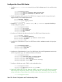
5. Configure the ATM interface of your Cisco DSL Router with an ATM permanent virtual circuit
(PVC), encapsulation type, and bridge group.
Router#configure terminal
Router(config)#interface atm 0
Router(config−if)#bridge−group 1
Router(config−if)#pvc <vpi/vci>
Router(config−if−atm−vc)#encapsulation aal5snap
Router(config−if−atm−vc)#no shut
Router(config−if−atm−vc)#end
6. Enable logging console on the Cisco DSL Router, and then write all the changes to memory.
Router#configure terminal
Router(config)#logging console
Router(config)#end
*Jan 1 00:00:00.100: %SYS−5−CONFIG_I: Configured from console by console
Router#write memory
Building configuration... [OK]
Router#
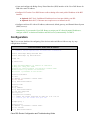
View Your Configuration
Your Cisco DSL Router should now be operational for Asymmetric Digital Subscriber Line (ADSL) service.
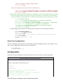
You can issue a show run command to see the configuration.
Router#show run
Building configuration...
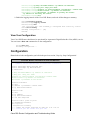
Configuration
Shown below is the configuration you built in the previous section, "Step−by−Step Configuration".
Cisco DSL Router with a PC Acting as a PPPoE Client
!−−− Comments contain explanations and additional information.
service timestamps debug datetime msec
service timestamps log datetime msec
!
no ip routing
!
interface ethernet0
no shut
no ip address
no ip directed−broadcast
bridge−group 1
!
interface atm0
no shut
no ip address
no ip directed−broadcast
no atm ilmi−keepalive
pvc <vpi/vci>
encapsulation aal5snap
!−−− Common PVC values supported by ISPs are 0/35 or 8/35.
Cisco DSL Router Configuration and Troubleshooting Guide
!−−− Confirm your PVC values with your ISP.
!
bridge−group 1
!
bridge 1 protocol ieee
!
end
Troubleshoot Your Configuration
If your ADSL service is not working properly, see Troubleshooting a PC PPPoE Client.
Previous Page
Main Page
All contents are Copyright © 1992−−2003 Cisco Systems, Inc. All rights reserved. Important Notices and Privacy Statement.
Cisco DSL Router Configuration and Troubleshooting
Guide
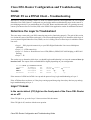
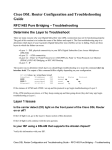
RFC1483 Bridging with IRB – Troubleshooting
Determine the Layer to Troubleshoot
There are many reasons why your Digital Subscriber Line (DSL) connection may not be functioning properly.
The goal of this section is to isolate the cause of the failure and repair it. The first troubleshooting step is to
determine which layer of your Asynchronous Digital Subscriber Line (ADSL) service is failing. There are
three layers in which the failure can occur.
• Layer 1 – DSL physical connectivity to your ISP's Digital Subscriber Line Access Multiplexer
(DSLAM)
• Layer 2.1 – ATM connectivity
• Layer 2.2 – Point−to−Point Protocol over ATM (PPPoA), Point−to−Point Protocol over Ethernet
(PPPoE), RFC1483 Bridging, or RFC1483 Routing
• Layer 3 – IP
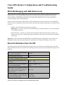
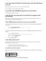
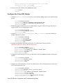
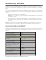
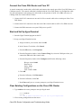
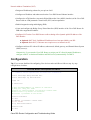
The easiest way to determine which layer you should begin troubleshooting is to issue the command show ip
interface brief. The output of this command differs slightly depending on your configuration.
827−ESC#show ip interface brief
Interface
IP−Address
OK?
ATM0
unassigned
YES
ATM0.1
unassigned
YES
Ethernet0
10.10.10.1
YES
Method
Status
manual up
unset
up
manual
up
Protocol
up
up
up
If the statuses of ATM0 and ATM0.1 are up and the protocol is up, begin troubleshooting at Layer 2.
If the ATM interfaces are down, or if they keep coming up and then going down (they don't stay up and up),
begin troubleshooting at Layer 1.
Cisco DSL Router Configuration and Troubleshooting Guide
Layer 1 Issues
Is the carrier detect (CD) light on the front panel of the Cisco DSL Router
on or off?
If the CD light is on, go to the Layer 2 Issues section of this document.
If the CD light is off, continue with the next question.
Is your ISP using a DSLAM that supports the Alcatel chipset?
Verify this information with your ISP.
Is the DSL port on the back of the Cisco DSL Router plugged into the
DSL wall jack?
If the DSL port is not plugged into the DSL wall jack, connect the port to the wall with a 4−pin or 6−pin
RJ−11 cable. This is a standard telephone cable.
Is the ATM interface in an administratively down state?
To determine if the ATM0 interface is administratively down, issue the following command in enable mode
on the router:
Router#show interface atm 0
ATM0 is administratively down, line protocol is down
<... snipped ...>
If the ATM0 interface status is administratively down, issue the no shutdown command under the ATM0
interface.
Router#configure terminal
Enter configuration commands, one per line. End with CNTL/Z.
Router(config)#interface atm 0
Router(config−if)#no shut
Router(config−if)#end
Router#write memory
Is the cable pinout correct?
If the ATM0 interface status is down and down, the router is not seeing a carrier on the ADSL line. This
generally indicates one of two issues:
1. The active pins on the DSL wall jack are incorrect.
2. Your ISP has not turned up ADSL service on this wall jack.
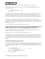
Cisco DSL Router xDSL Port Pinouts
The RJ−11 connector provides an xDSL connection to external media via a standard RJ−11 6−pin modular
jack.
Cisco DSL Router Configuration and Troubleshooting Guide
Pin
Description
3
XDSL_Tip
4
XDSL_Ring
To determine if the ATM0 interface is down and down, issue the show interface atm 0 command from
enable mode of the router:
Router#show interface atm 0
ATM0 is down, line protocol is down
<... snipped ...>
If the ATM interface is down and down—not administratively down—check the pinout of your DSL wall
jack. The DSL Router uses a standard RJ−11 (4−pin or 6−pin) cable to provide the ADSL connection to the
wall jack. The center pair of pins on the RJ−11 cable is used to carry the ADSL signal (pins 3 and 4 on a
6−pin cable, or pins 2 and 3 on a 4− pin cable).
If you are sure you have the right pins on the wall jack and the ATM0 interface is still down and down,
replace the RJ−11 cable between the ADSL port and your wall jack. If the interface is still down and down
after replacing the RJ−11 cable, contact your ISP and have the ISP verify that ADSL service has been enabled
on the wall jack you are using.
If you are not sure what pins on your wall jack are active, ask your ISP.
Do you have the correct power supply for the Cisco 827?
If you have verified that your ADSL cable is good and that you have the correct pinouts, the next step is to
make sure you have the correct power supply for the 827.
Note: The 827 does not use the same power supply as other 800 series routers.
To determine if you have the correct power supply, on the back of the power adapter look for Output +12V
0.1A, −12V 0.1A, +5V 3A, −24V 0.12A, and −71V 0.12A. If your power supply is missing the +12V and
−12V feeds, then it is for a different Cisco 800 series router and will not work on the 827. Note that if you use
the wrong power supply, the Cisco 827 will power up but will be unable to train up (connect) to the ISP
DSLAM.
Is the DSL operating−mode correct?
If everything up to this point in the Layer 1 troubleshooting procedure is correct, the next step is to make sure
you have the correct DSL operating mode. Cisco recommends using dsl operating−mode auto if you are not
sure what DMT technology your ISP is using. The commands to configure operating−mode autodetection are
as follows:
Router#configure terminal
Enter configuration commands, one per line.
Router(config)#interface atm 0
Router(config−if)#dsl operating−mode auto
Router(config−if)#end
Router#write memory
End with CNTL/Z.
Cisco DSL Router Configuration and Troubleshooting Guide
Is the circuit tested/provisioned correctly?
Obtain this information from your ISP or telephone company.
Layer 2 Issues
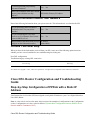
Do you have the correct PVC values (VPI/VCI)?
Complete the following steps to determine whether you have the correct virtual path identifier/virtual circuit
identifier (VPI/VCI) values configured on the router.
1. Verify your version of Cisco IOS® software.
Important: This will not work with Cisco IOS Software Release 12.1(1)XB.
Router#show version
!−−− Used to determine your Cisco IOS version.
Cisco Internetwork Operating System Software
IOS (tm) C820 Software (C820−OSY656I−M), Version 12.1(3)XG3,
EARLY DEPLOYMENT RELEASE SOFTWARE (fc1)
!−−− The two lines immediately preceding appear on one line on the router.
TAC:Home:SW:IOS:Specials for info
Copyright (c) 1986−2000 by cisco Systems, Inc.
Compiled Wed 20−Dec−00 16:44 by detang
Image text−base: 0x80013170, data−base: 0x80725044
<... snipped ...>
2. Configure the router for debug logging.
Router#configure terminal
Enter configuration commands, one per line. End with CNTL/Z.
Router(config)#logging console
Router(config)#logging buffer
Router(config)#service timestamp debug datetime msec
Router(config)#service timestamp log datetime msec
Router(config)#end
Router#write memory
Building configuration...
[OK]
Router#terminal monitor
3. Enable debugging on the router.
Router#debug atm events
ATM events debugging is on
Router#
2d18h:
2d18h: RX interrupt: conid =
2d18h: Data Cell received on
!−−− Your VPI/VCI.
2d18h:
2d18h: RX interrupt: conid =
2d18h: Data Cell received on
2d18h:
2d18h: RX interrupt: conid =
2d18h: Data Cell received on
2d18h:
2d18h: RX interrupt: conid =
2d18h: Data Cell received on
0, rxBd = 0x80C7EF74 length=52
vpi = 8 vci = 35
0, rxBd = 0x80C7EEC0 length=52
vpi = 8 vci = 35
0, rxBd = 0x80C7EECC length=52
vpi = 8 vci = 35
0, rxBd = 0x80C7EED8 length=52
vpi = 8 vci = 35
Cisco DSL Router Configuration and Troubleshooting Guide
4. Make sure you have debug ATM events running on the Cisco DSL Router, and then go to a working
Internet connection and begin to ping the IP address your ISP statically assigned to you.
It does not matter whether you have configured this IP address on the Cisco DSL Router. What is
important is that your ATM interface is up/up and that you are pinging the IP address your ISP gave
you. If you don't see the expected output after the ping test, contact your ISP for support.
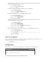
5. Disable debugging on the router.
<< wait 60 seconds >>
Router#undebug all
!−−− Used to turn off the debug events.
All possible debugging has been turned off.
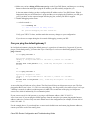
Verify your VPI/VCI values, and then make the necessary changes to your configuration.
If you do not see output during the 60 seconds of debugging, contact your ISP.
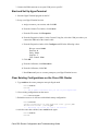
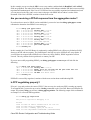
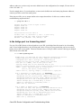
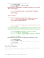
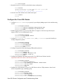
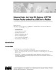
Can you ping the default gateway?
In a bridged environment, pinging the default gateway is a good test of connectivity. In general, if you can
ping to your default gateway, you know that Layer 1 and Layer 2 services are functioning properly. Issue the
ping command:
Router#ping 192.168.1.1
Type escape sequence to abort.
Sending 5, 100−byte ICMP Echos to 192.168.1.1, timeout is 2 seconds:
.!!!!
Success rate is 80 percent (4/5), round−trip min/avg/max = 44/44/48 ms
Router#
OR
Router#ping 192.168.1.1
Type escape sequence to abort.
Sending 5, 100−byte ICMP Echos to 192.168.1.1, timeout is 2 seconds:
!!!!!
Success rate is 100 percent (5/5), round−trip min/avg/max = 44/44/48 ms
Router#
A successful ping will take one of two forms. The first form will show an 80 percent success rate. The first
ping packet that is sent is lost (.!!!!). This is a successful ping—the first packet is lost while a Layer 2 to Layer
3 binding is created via address resolution protocol (ARP). The second form of the ping is a 100 percent
success rate, which is indicated by five exclamation points.
If your success rate is 80−100 percent, try to ping a valid Internet address (198.133.219.25 is
www.cisco.com). If you can ping the default gateway from the router but you cannot ping another Internet
address, make sure you have only one static default route in the configuration (for example, IP route 0.0.0.0
0.0.0.0 192.168.1.1).
For the example above, if you already have a correct static default route and cannot ping Internet addresses,
contact your ISP to resolve the routing issue.
Cisco DSL Router Configuration and Troubleshooting Guide
If the ping test fails (a ping success rate of 0 percent), you see output similar to the output shown below. In
this case, continue with the troubleshooting steps that follow.
Router#ping 192.168.1.1
Type escape sequence to abort.
Sending 5, 100−byte ICMP Echos to 192.168.1.1, timeout is 2 seconds:
.....
Success rate is 0 percent (0/5)
Router#
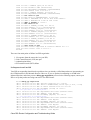
Is the bridge port in a forwarding state?
For your Cisco DSL Router to forward packets to your ISP, your bridged interface must be in a forwarding
state. If your bridged interface is in a blocking state, there is a loop in your network that you have to remove
before you are able to pass traffic. The most common cause of a loop in a ADSL network is having two
bridged ADSL circuits to the same ISP.
Router#show spanning−tree
Bridge group 1 is executing the ieee compatible Spanning Tree protocol
Bridge Identifier has priority 32768, address 0000.0c5d.3694
Configured hello time 2, max age 20, forward delay 15
We are the root of the spanning tree
Topology change flag not set, detected flag not set
Number of topology changes 7 last change occurred 00:03:45 ago from ATM0.1
Times: hold 1, topology change 35, notification 2
hello 2, max age 20, forward delay 15
Timers: hello 0, topology change 0, notification 0, aging 300
Port 3 (ATM0) of Bridge group 1 is forwarding
Port path cost 1562, Port priority 128, Port Identifier 128.3.
Designated root has priority 32768, address 0000.0c5d.3694
Designated bridge has priority 32768, address 0000.0c5d.3694
Designated port id is 128.3, designated path cost 0
Timers: message age 0, forward delay 0, hold 0
Number of transitions to forwarding state: 4
BPDU: sent 49843, received 0
Router#
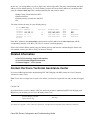
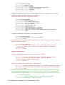
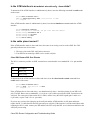
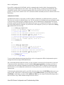
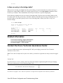
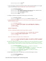
Is there an entry in the bridge table?
When you are sure that your bridged interface is forwarding, you need to determine if you have the Layer 2
media access control (MAC) address of your ISP's gateway router. Use the show bridge command to check
for the Layer 2 address. This command lists all the Layer 2 entries for a specific bridge group.
Router#show bridge
Total of 300 station blocks, 299 free
Codes: P − permanent, S − self
Bridge Group 1:
Address
0010.7bb9.bd1a
Action
forward
Interface
ATM0
Age
0
Router#
Cisco DSL Router Configuration and Troubleshooting Guide
RX count
10
TX count
9
In this case, you will probably see only a single entry in the bridge table. That entry should include the MAC
address of your default gateway. To verify whether you have the correct MAC address in your bridge table,
issue the command show arp. This command generally has four or more entries:
• Bridge Group Virtual Interface (BVI)
• Ethernet interface
• Default gateway (connected to the BVI)
• PC
You need to know the entry for your default gateway.
Router#show arp
Protocol Address
Internet 192.168.1.2
Internet 192.168.1.1
Internet 10.1.1.1
Internet 10.1.1.2
Router#
Age (min)
−
10
108
−
Hardware Addr
0000.0c11.4e4c
0010.7bb9.db1a
0030.80c5.a665
0030.96f8.45b8
Type
ARPA
ARPA
ARPA
ARPA
Interface
BVI1
BVI1
Ethernet0
Ethernet0
If the MAC address in the show bridge output matches a MAC address in the show arp output and the
corresponding interface is the BVI, your Layer 2 network is working properly.
If there isn't a MAC address match, ping your default gateway and issue the commands again. If there still
isn't a match, contact your ISP to verify your network settings.
Related Information
• Cisco DSL Technology Support Information
• Cisco DSL Product Support Information
• Technical Support − Cisco Systems
Contact the Cisco Technical Assistance Center
If you need additional assistance implementing RFC1483 bridging with IRB, contact the Cisco Technical
Assistance Center (TAC).
Note: To use the Case Open tool to open a case online, you must be a registered user and you must be logged
in.
Call the TAC
If you do not have a service contract with Cisco and need assistance implementing RFC1483 bridging with
IRB, direct your web browser to Cisco's Warranty Status Tool.
RFC1483 Bridging with IRB
Implementations Page
Main Page
All contents are Copyright © 1992−−2003 Cisco Systems Inc. All rights reserved. Important Notices and Privacy Statement.
Cisco DSL Router Configuration and Troubleshooting Guide
Cisco DSL Router Configuration and Troubleshooting
Guide
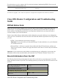
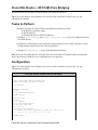
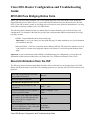
RFC1483 Bridging with IRB Online Form
Before you can successfully configure your Cisco DSL Router with Asymmetric Digital Subscriber Line
(ADSL) service, you need specific information from your Internet Service Provider (ISP). If your ISP is
unsure, unable, or unwilling to provide answers to the questions outlined below, you may not be able to
correctly configure your Cisco DSL Router.
Forms are provided to help you obtain and record the information you need to build your own configuration.
Choose one of two formats for each form. Note that each format has different requirements for saving text that
you enter.
• HTML – Enter information in the forms on this page.
Important: To save your entries you must print this page. No other methods to save your information
are available at this time.
• Microsoft Word – Click here to open the forms in Microsoft Word. Fill in the forms, and then save
them on your local drive. Return to this page and continue with Choose Your Next Step at the bottom
of this page.
Important: If you need assistance with building or troubleshooting your configuration, you must have the
information in these forms accessible before you contact the Cisco Technical Assistance Center (TAC).
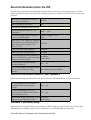
Record Information from the ISP
The following form includes questions about the name of the reseller where you purchased your Cisco DSL
Router and about the name of your ISP. The remaining questions you must ask your ISP. Fill in answers to all
questions.
Where did you purchase the Cisco DSL
Router (name of Reseller)?
Reseller
What is the name of your ISP?
ISP
Information to Request from Your ISP
Is your ISP offering you DMT or CAP
modulation?
DMT
Is your ISP using an Alcatel compliant or
a Cisco Systems DSLAM?
Alcatel Compliant Cisco
Other
CAP
What VPI/VCI pair values (also called the
PVC number) is your ISP using for your
VPI VCI
DSL connection? For example, 8/35
VPI=8, VCI=35.
If your ISP assigned a static IP address for
IP Address
the Cisco DSL Router, what is the public
Subnet Mask
IP address and subnet mask?
Cisco DSL Router Configuration and Troubleshooting Guide
Is your ISP providing a dynamically
generated IP address?
Yes
No
What is the IP address of the ISP's default
gateway (also called the next hop
ISP Default Gateway IP Address
address)?
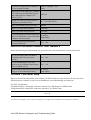
Record Information About Your Network
Record the following information about your private network. This information is not related to the ISP.
Are you performing Network Address
Translation (NAT) on your private
network?
Yes
No
Are you configuring the Cisco DSL
Router to act as a Dynamic Host Control
Protocol (DHCP) server?
Yes
No
What IP address and subnet mask will you IP Address
configure on the Ethernet0 interface?
Subnet Mask
Choose Your Next Step
When you have all the information you need from your ISP, select one of the following options based on
whether you have a new installation or are troubleshooting an existing one.
New DSL configuration
Troubleshooting my existing DSL connection
Previous Page
Main Page
All contents are Copyright © 1992−−2003 Cisco Systems Inc. All rights reserved. Important Notices and Privacy Statement.
Cisco DSL Router Configuration and Troubleshooting
Guide
Step−by−Step Configuration of PPPoA with a Static IP
Address
Your Internet Service Provider (ISP) has assigned a static public IP address to your Cisco Digital Subscriber
Line (DSL) Router.
Note: A color code is used to relate tasks in this section with examples of configurations in the Configuration
section. Configurations are color−coded as follows: Dynamic Host Configuration Protocol (DHCP) Server,
Network Address Translation (NAT).
Cisco DSL Router Configuration and Troubleshooting Guide
Step−by−Step Configuration
Important: Before you begin, close all programs on the PC that might be monitoring your COM port.
Devices such as PDAs and digital cameras often place programs in the system tray that will render your COM
port unusable for configuring your Cisco DSL Router.
Connect the Cisco DSL Router and Your PC
A console connection is made with a rolled cable and connects the console port of the Cisco DSL Router to a
COM port on a PC. The console cable that is included with the Cisco DSL Router is a flat light blue cable.
For more information on the pinouts of a rolled cable, or the pinouts of an RJ−45 to DB9 converter, see the
Cabling Guide for Console and AUX Ports.
1. Connect the RJ−45 connector on one end of a Cisco console cable to the console port of the Cisco
DSL Router.
2. Connect the RJ−45 connector at the other end of the console cable to an RJ−45 to DB9 converter.
3. Connect the DB9 connector to an open COM port on your PC.
Start and Set Up HyperTerminal
1. Start the HyperTerminal program on the PC.
2. Set up your HyperTerminal session.
a. Assign a name to your session, and click OK.
b. From the Connect To window, click Cancel.
c. From the File menu, click Properties.
d. From the Properties window, in the Connect Using list, select the COM port where you
connect the DB9 end of the console cable.
e. From the Properties window click Configure and fill in the following values:
Bits per second: 9600
Data bits: 8
Parity: None
Stop bits: 1
Flow Control: None
f. Click OK.
g. From the Call menu, click Disconnect.
h. From the Call menu, click Call.
i. Press Enter until you see a router prompt on your HyperTerminal screen.
Cisco DSL Router Configuration and Troubleshooting Guide
Clear Existing Configurations on the Cisco DSL Router
1. Type enable at the router prompt to enter privileged mode.
Router>enable
Router#
!−−− The # symbol indicates that you are in privileged mode.
2. Clear existing configurations on the router.
Router#write erase
3. Reload the router so it will boot with a blank startup configuration.
Router#reload
System configuration has been modified. Save? [yes/no]:no
Proceed with reload? [confirm]yes
!−−− Reloading the router may take a few minutes.
4. After the router has reloaded, enter enable mode again.
Router>enable
Router#
Configure the Cisco DSL Router
1. Configure service timestamp to properly log and display debug output in the troubleshooting
section.
Router#configure terminal
Router(config)#service timestamps debug datetime msec
Router(config)#service timestamps log datetime msec
Router(config)#end
2. Disable the logging console on your Cisco DSL Router to suppress console messages that may be
triggered while you are configuring the router.
Router#configure terminal
Router(config)#no logging console
Router(config)#end
3. Configure ip routing, ip subnet−zero, and ip classless to provide flexibility in
routing configuration options.
Router#configure terminal
Router(config)#ip routing
Router(config)#ip subnet−zero
Router(config)#ip classless
Router(config)#end
4. Configure an IP address and subnet mask on the Cisco DSL Router Ethernet interface.
(Optional) Enable NAT inside on the Ethernet interface.
Router#configure terminal
Router(config)#interface ethernet 0
Router(config−if)#ip address <ip address> <subnet mask>
Router(config−if)#ip nat inside
Router(config−if)#no shut
Router(config−if)#end
5. Configure the ATM interface of your Cisco DSL Router with an ATM permanent virtual circuit
(PVC), encapsulation type, and Dialer pool.
Router#configure terminal
Cisco DSL Router Configuration and Troubleshooting Guide
Router(config)#interface atm 0
Router(config−if)#pvc <vpi/vci>
Router(config−if−atm−vc)#encapsulation aal5mux ppp dialer
Router(config−if−atm−vc)#dialer pool−member 1
Router(config−if−atm−vc)#no shut
Router(config−if−atm−vc)#end
6. Configure the Dialer interface of your Cisco DSL Router for Point−to−Point Protocol over ATM
(PPPoA) with a static IP address.
(Optional) Enable NAT outside on the Dialer interface.
Router#configure terminal
Router(config)#interface dialer 1
Router(config−if)#ip address <IP address> <subnet mask>
Router(config−if)#no ip directed−broadcast
Router(config−if)#ip nat outside
Router(config−if)#encapsulation ppp
Router(config−if)#dialer pool 1
Router(config−if)#ppp chap hostname <username>
Router(config−if)#ppp chap password <password>
Router(config−if)#ppp pap sent−username <username> password <password>
Router(config−if)#end
7. Configure a default route using Dialer1 as the outbound interface.
Router#configure terminal
Router(config)#ip route 0.0.0.0 0.0.0.0 dialer1
Router(config)#end
8. Configure global NAT commands on the Cisco DSL Router to allow sharing of the static public IP
address of the Dialer interface.
Router#configure terminal
Router(config)#ip nat inside source list 1 interface dialer1 overload
Router(config)#access−list 1 permit <ip network address of ethernet0>
<wildcard mask>
Router(config)#end
Optional Configurations
NAT Pool, if additional IP addresses have been provided by your ISP.
Router(config)#ip nat inside source list 1 interface dialer1 overload
Router(config)#ip nat pool <nat pool name> <first ip address>
<last ip address> netmask <subnet mask>
Router(config)#end
Static NAT, if Internet users require access to internal servers.
Router(config)#ip nat inside source static tcp <inside ip address of server>
{80 or 25} <outside well−known ip address of server> {80 or 25} extendable
Router(config)#end
9. (Optional) Configure the Cisco DSL Router as a DHCP server with a pool of IP addresses to assign to
hosts connected to the Ethernet interface of the Cisco DSL Router. The DHCP server dynamically
assigns an IP address, Domain Name Server (DNS), and the default gateway IP address to your hosts.
Router#configure terminal
Router(config)#ip dhcp excluded−address <ip address of ethernet0>
Router(config)#ip dhcp pool <dhcp pool name>
Router(dhcp−config)#network <ip network address of ethernet0> <subnet mask>
Cisco DSL Router Configuration and Troubleshooting Guide
Router(dhcp−config)#default−router <ip address of ethernet0>
Router(dhcp−config)#dns−server <ip address of primary dns server>
<ip address of secondary dns server>
Router(dhcp−config)#end
10. Enable the logging console on the Cisco DSL Router, and write all the changes to memory.
Router#configure terminal
Router(config)#logging console
Router(config)#end
*Jan 1 00:00:00.100: %SYS−5−CONFIG_I: Configured from console by console
Router#write memory
Building configuration... [OK]
Router#
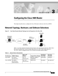
View Your Configuration
Your Cisco DSL Router should now be operational for Asymmetric Digital Subscriber Line (ADSL) service.
You can issue a show run command to see the configuration.
Router#show run
Building configuration...
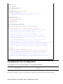
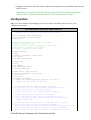
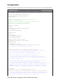
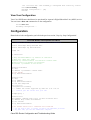
Configuration
Shown below is the configuration you built in the previous section, "Step−by−Step Configuration".
Cisco DSL Router with a Static IP Address
!−−− Comments contain explanations and additional information.
service timestamps debug datetime msec
service timestamps log datetime msec
ip subnet−zero
!
ip dhcp excluded−address <ip address of ethernet0>
ip dhcp pool <dhcp pool name>
network <ip network address of ethernet0> <subnet mask>
default−router <ip address of ethernet0>
dns−server <ip address of dns server>
!
interface ethernet0
no shut
ip address <ip address> <subnet mask>
ip nat inside
no ip directed−broadcast
!
interface atm0
no shut
no ip address
no ip directed−broadcast
no ip mroute−cache
pvc <vpi/vci>
encapsulation aal5mux ppp dialer
dialer pool−member 1
!−−− Common PVC values supported by ISPs are 0/35 or 8/35.
!−−− Confirm your PVC values with your ISP
!
!
interface dialer1
ip address <ip address> <subnet mask>
Cisco DSL Router Configuration and Troubleshooting Guide
no ip directed−broadcast
ip nat outside
encapsulation ppp
dialer pool 1
ppp chap hostname <username>
ppp chap password <password>
ppp pap sent−username <username> password <password>
!
ip nat inside source list 1 interface dialer1 overload
!−−− If you have a pool (a range) of public IP addresses provided
!−−− by your ISP, you can use a NAT Pool. Replace
!−−− ip nat inside source list 1 interface dialer1 overload
!−−− with the following two configuration statements:
!−−− ip nat inside source list 1 pool <nat pool name> overload
!−−− ip nat pool <nat pool name> <first ip address> <last ip address>
!−−− netmask <subnet mask>
!−−− If Internet users require access to an internal server, you can
!−−− add the following static NAT configuration statement:
!−−− ip nat inside source static tcp <inside ip address of server> {80 or 25}
!−−− <outside well−known ip address of server> {80 or 25} extendable
!−−− Note: TCP port 80 (HTTP/web) and TCP port 25 (SMTP/mail) are used
!−−− for this example. You can open other TCP or UDP ports, if needed.
!
ip classless
ip route 0.0.0.0 0.0.0.0 dialer1
access−list 1 permit <ip network address of ethernet0> <wildcard mask>
!−−− In this configuration, access−list 1 defines a standard access list
!−−− permitting the addresses that NAT will translate. For example, if
!−−− your private IP network was 10.10.10.0, configuring
!−−− access−list 1 permit 10.10.10.0 0.0.0.255 would allow NAT to translate
!−−− packets with source addresses between 10.10.10.0 and 10.10.10.255.
!
end
Troubleshoot Your Configuration
If your ADSL service is not working properly, see Troubleshooting PPPoA.
Previous Page
Main Page
All contents are Copyright © 1992−−2003 Cisco Systems, Inc. All rights reserved. Important Notices and Privacy Statement.
Cisco DSL Router Configuration and Troubleshooting
Guide
Step−by−Step Configuration of PPPoA with a Dynamic IP
Address
Your Internet Service Provider (ISP) has assigned a dynamic public IP address to your Cisco Digital
Subscriber Line (DSL) Router.
Cisco DSL Router Configuration and Troubleshooting Guide
Note: A color code is used to relate tasks in this section with examples of configurations in the Configuration
section. Configurations are color−coded as follows: Dynamic Host Configuration Protocol (DHCP) Server,
Network Address Translation (NAT).
Step−by−Step Configuration
Important: Before you begin, close all programs on the PC that might be monitoring your COM port.
Devices such as PDAs and digital cameras often place programs in the system tray that will render your COM
port unusable for configuring your Cisco DSL Router.
Connect the Cisco DSL Router and Your PC
A console connection is made with a rolled cable and connects the console port of the Cisco DSL Router to a
COM port on a PC. The console cable that is included with the Cisco DSL Router is a flat light blue cable.
For more information on the pinouts of a rolled cable, or the pinouts of an RJ−45 to DB9 converter, see
Cabling Guide for Console and AUX Ports.
1. Connect the RJ−45 connector on one end of a Cisco console cable to the console port of the Cisco
DSL Router.
2. Connect the RJ−45 connector at the other end of the console cable to an RJ−45 to DB9 converter.
3. Connect the DB9 connector to an open COM port on your PC.
Start and Set Up HyperTerminal
1. Start the HyperTerminal program on the PC.
2. Set up your HyperTerminal session.
a. Assign a name to your session, and click OK.
b. In the Connect To window, click Cancel.
c. From the File menu, click Properties.
d. From the Properties window, in the Connect Using list, select the COM port where you
connect the DB9 end of the console cable.
e. From the Properties window, click Configure and fill in the following values:
Bits per second: 9600
Data bits: 8
Parity: None
Stop bits: 1
Flow Control: None
f. Click OK.
g. From the Call menu, click Disconnect.
h. From the Call menu, click Call.
Cisco DSL Router Configuration and Troubleshooting Guide
i. Press Enter until you see a router prompt on your HyperTerminal screen.
Clear Existing Configurations on the Cisco DSL Router
1. Type enable at the router prompt to enter privileged mode.
Router>enable
Router#
!−−− The # symbol indicates that you are in privileged mode.
2. Clear existing configurations on the router.
Router#write erase
3. Reload the router so it will boot with a blank startup configuration.
Router#reload
System configuration has been modified. Save? [yes/no]:no
Proceed with reload? [confirm]yes
!−−− Reloading the router may take a few minutes.
4. After the router has reloaded, enter enable mode again.
Router>enable
Router#
Configure the Cisco DSL Router
1. Configure service timestamp to properly log and display debug output in the troubleshooting
section.
Router#configure terminal
Router(config)#service timestamps debug datetime msec
Router(config)#service timestamps log datetime msec
Router(config)#end
2. Disable the logging console on your Cisco DSL Router to suppress console messages that may be
triggered while you are configuring the router.
Router#configure terminal
Router(config)#no logging console
Router(config)#end
3. Configure ip routing, ip subnet−zero, and ip classless to provide flexibility in
routing configuration options.
Router#configure terminal
Router(config)#ip routing
Router(config)#ip subnet−zero
Router(config)#ip classless
Router(config)#end
4. Configure an IP address and subnet mask on the Cisco DSL Router Ethernet interface.
(Optional) Enable NAT inside on the Ethernet interface.
Router#configure terminal
Router(config)#interface ethernet 0
Router(config−if)#ip address <ip address> <subnet mask>
Router(config−if)#ip nat inside
Router(config−if)#no shut
Router(config−if)#end
5. Configure the ATM interface of your Cisco DSL Router with an ATM permanent virtual circuit
(PVC), encapsulation type, and Dialer pool.
Cisco DSL Router Configuration and Troubleshooting Guide
Router#configure terminal
Router(config)#interface atm 0
Router(config−if)#pvc <vpi/vci>
Router(config−if−atm−vc)#encapsulation aal5mux ppp dialer
Router(config−if−atm−vc)#dialer pool−member 1
Router(config−if−atm−vc)#no shut
Router(config−if−atm−vc)#end
6. Configure the Dialer interface of your Cisco DSL Router for Point−to−Point Protocol over ATM
(PPPoA) to enable a dynamic IP address to be assigned.
(Optional) Enable NAT outside on the Dialer interface.
Router#configure terminal
Router(config)#interface dialer 1
Router(config−if)#ip address negotiated
Router(config−if)#no ip directed−broadcast
Router(config−if)#ip nat outside
Router(config−if)#encapsulation ppp
Router(config−if)#dialer pool 1
Router(config−if)#ppp chap hostname <username>
Router(config−if)#ppp chap password <password>
Router(config−if)#ppp pap sent−username <username> password <password>
Router(config−if)#end
7. Configure a default route using Dialer1 as the outbound interface.
Router#configure terminal
Router(config)#ip route 0.0.0.0 0.0.0.0 dialer1
Router(config)#end
8. Configure global NAT commands on the Cisco DSL Router to allow sharing of the dynamic public IP
address of the Dialer interface.
Router#configure terminal
Router(config)#ip nat inside source list 1 interface dialer1 overload
Router(config)#access−list 1 permit <ip network address of ethernet0>
<wildcard mask>
Router(config)#end
Optional Configurations
NAT Pool, if additional IP addresses have been provided by your ISP.
Router(config)#ip nat inside source list 1 interface dialer1 overload
Router(config)#ip nat pool <nat pool name> <first ip address>
<last ip address> netmask <subnet mask>
Router(config)#end
Static NAT, if Internet users require access to internal servers.
Router(config)#ip nat inside source static tcp <inside ip address of server>
{80 or 25} <outside well−known ip address of server> {80 or 25} extendable
Router(config)#end
9. (Optional) Configure the Cisco DSL Router as a DHCP server with a pool of IP addresses to assign to
hosts connected to the Ethernet interface of the Cisco DSL Router. The DHCP server dynamically
assigns an IP address, Domain Name Server (DNS), and the default gateway IP address to your hosts.
Router#configure terminal
Router(config)#ip dhcp excluded−address <ip address of ethernet0>
Router(config)#ip dhcp pool <dhcp pool name>
Cisco DSL Router Configuration and Troubleshooting Guide
Router(dhcp−config)#network <ip network address of ethernet0> <subnet mask>
Router(dhcp−config)#default−router <ip address of ethernet0>
Router(dhcp−config)#dns−server <ip address of primary dns server>
<ip address of secondary dns server>
Router(dhcp−config)#end
10. Enable the logging console on the Cisco DSL Router, and write all the changes to memory.
Router#configure terminal
Router(config)#logging console
Router(config)#end
*Jan 1 00:00:00.100: %SYS−5−CONFIG_I: Configured from console by console
Router#write memory
Building configuration... [OK]
Router#
View Your Configuration
Your Cisco DSL Router should now be operational for Asymetric Digital Subscriber Line (ADSL) service.
You can issue a show run command to see the configuration.
Router#show run
Building configuration...
Configuration
Shown below is the configuration you built in the previous section, "Step−by−Step Configuration".
Cisco DSL Router with a Dynamic IP Address
!−−− Comments contain explanations and additional information.
service timestamps debug datetime msec
service timestamps log datetime msec
ip subnet−zero
!
ip dhcp excluded−address <ip address of ethernet0>
ip dhcp pool <dhcp pool name>
network <ip network address of ethernet0> <subnet mask>
default−router <ip address of ethernet0>
dns−server <ip address of dns server>
!
interface ethernet0
no shut
ip address <ip address> <subnet mask>
ip nat inside
no ip directed−broadcast
!
interface atm0
no shut
no ip address
no ip directed−broadcast
no ip mroute−cache
pvc <vpi/vci>
encapsulation aal5mux ppp dialer
dialer pool−member 1
!−−− Common PVC values supported by ISPs are 0/35 or 8/35.
!−−− Confirm your PVC values with your ISP.
!
interface dialer1
ip address negotiated
Cisco DSL Router Configuration and Troubleshooting Guide
no ip directed−broadcast
ip nat outside
encapsulation ppp
dialer pool 1
ppp chap hostname <username>
ppp chap password <password>
ppp pap sent−username <username> password <password>
!
ip nat inside source list 1 interface dialer1 overload
!−−− If you have a pool (a range) of public IP addresses provided
!−−− by your ISP, you can use a NAT Pool. Replace
!−−− ip nat inside source list 1 interface dialer1 overload
!−−− with the following two configuration statements:
!−−− ip nat inside source list 1 pool <nat pool name> overload
!−−− ip nat pool <nat pool name> <first ip address> <last ip address>
!−−− netmask <subnet mask>
!−−− If Internet users require access to an internal server, you can
!−−− add the following static NAT configuration statement:
!−−− ip nat inside source static tcp <inside ip address of server> {80 or 25}
!−−− <outside well−known ip address of server> {80 or 25} extendable
!−−− Note: TCP port 80 (HTTP/web) and TCP port 25 (SMTP/mail) are used
!−−− for this example. You can open other TCP or UDP ports, if needed.
!
ip classless
ip route 0.0.0.0 0.0.0.0 dialer1
access−list 1 permit <ip network address of ethernet0> <wildcard mask>
!−−− In this configuration, access−list 1 defines a standard access list
!−−− permitting the addresses that NAT will translate. For example, if
!−−− your private IP network was 10.10.10.0, configuring
!−−− access−list 1 permit 10.10.10.0 0.0.0.255 would allow NAT to translate
!−−− packets with source addresses between 10.10.10.0 and 10.10.10.255.
!
end
Troubleshoot Your Configuration
If your ADSL service is not working properly, see Troubleshooting PPPoA.
Previous Page
Main Page
All contents are Copyright © 1992−−2003 Cisco Systems, Inc. All rights reserved. Important Notices and Privacy Statement.
Cisco DSL Router Configuration and Troubleshooting
Guide
Cisco DSL Router − PPPoA with a Dynamic IP Address
Your Internet Service Provider (ISP) has assigned a dynamic public IP address to your Cisco Digital
Subscriber Line (DSL) Router.
Cisco DSL Router Configuration and Troubleshooting Guide
Tip: If you are not familiar with configuring Cisco devices and would like to follow a step−by−step
configuration, click here.
Tasks to Perform
Note: A color code is used to relate tasks in this section with examples of configurations in the Configuration
section. Configurations are color−coded as follows: Dynamic Host Configuration Protocol (DHCP) Server,
Network Address Translation (NAT).
• Design an IP addressing scheme for your private LAN.
• Configure an IP address and subnet mask on the Cisco DSL Router Ethernet interface.
• Configure the ATM interface (Asymetric Digital Subscriber Line (ADSL) interface) of the Cisco DSL
Router with an ATM permanent virtual circuit (PVC) and encapsulation.
• Create and configure the Dialer interface of the Cisco DSL Router for Point−to−Point Protocol over
ATM (PPPoA) with a negotiated IP address.
• Configure NAT on the Cisco DSL Router to allow sharing of the dynamic public IP address of the
Dialer interface.
♦ Optional: NAT Pool, if additional IP addresses have been provided by your ISP.
♦ Optional: Static NAT, if Internet users require access to internal servers.
• Configure each host PC with an IP address, subnet mask, default gateway, and Domain Name System
(DNS) server(s).
Alternatively, if you want the Cisco DSL Router to assign your PC clients' dynamic IP addresses,
configure each PC to obtain an IP address and DNS server(s) automatically via DHCP.
Configuration
Tip: If you are not familiar with configuring Cisco devices and would like to follow a step−by−step
configuration, click here.
Cisco DSL Router with a Dynamic IP Address
!−−− Comments contain explanations and additional information.
service timestamps debug datetime msec
service timestamps log datetime msec
ip subnet−zero
!
ip dhcp excluded−address <ip address of ethernet0>
ip dhcp pool <dhcp pool name>
network <ip network address of ethernet0> <subnet mask>
default−router <ip address of ethernet0>
dns−server <ip address of dns server>
!
interface ethernet0
no shut
ip address <ip address> <subnet mask>
ip nat inside
no ip directed−broadcast
!
Cisco DSL Router Configuration and Troubleshooting Guide
interface atm0
no shut
no ip address
no ip directed−broadcast
no ip mroute−cache
pvc <vpi/vci>
encapsulation aal5mux ppp dialer
dialer pool−member 1
!−−− Common PVC values supported by ISPs are 0/35 or 8/35.
!−−− Confirm your PVC values with your ISP.
!
interface dialer1
ip address negotiated
no ip directed−broadcast
ip nat outside
encapsulation ppp
dialer pool 1
ppp chap hostname <username>
ppp chap password <password>
ppp pap sent−username <username> password <password>
!
ip nat inside source list 1 interface dialer1 overload
!−−− If you have a pool (a range) of public IP addresses provided
!−−− by your ISP, you can use a NAT Pool. Replace
!−−− ip nat inside source list 1 interface dialer1 overload
!−−− with the following two configuration statements:
!−−− ip nat inside source list 1 pool <nat pool name> overload
!−−− ip nat pool <nat pool name> <first ip address> <last ip address>
!−−− netmask <subnet mask>
!−−− If Internet users require access to an internal server, you can
!−−− add the following static NAT configuration statement:
!−−− ip nat inside source static tcp <inside ip address of server> {80 or 25}
!−−− <outside well−known ip address of server> {80 or 25} extendable
!−−− Note: TCP port 80 (HTTP/web) and TCP port 25 (SMTP/mail) are used
!−−− for this example. You can open other TCP or UDP ports, if needed.
!
ip classless
ip route 0.0.0.0 0.0.0.0 dialer1
access−list 1 permit <ip network address of ethernet0> <wildcard mask>
!−−− In this configuration, access−list 1 defines a standard access list
!−−− permitting the addresses that NAT will translate. For example, if
!−−− your private IP network was 10.10.10.0, configuring
!−−− access−list 1 permit 10.10.10.0 0.0.0.255 would allow NAT to translate
!−−− packets with source addresses between 10.10.10.0 and 10.10.10.255.
!
end
Troubleshoot Your Configuration
If your ADSL service is not working properly, see Troubleshooting PPPoA .
Previous Page
Main Page
All contents are Copyright © 1992−−2003 Cisco Systems Inc. All rights reserved. Important Notices and Privacy Statement.
Cisco DSL Router Configuration and Troubleshooting Guide
Cisco DSL Router Configuration and Troubleshooting
Guide
Cisco DSL Router – PPPoA with a Static IP Address
Your Internet Service Provider (ISP) has assigned a static public IP address to your Cisco Digital Subscriber
Line (DSL) Router.
Tip: If you are not familiar with configuring Cisco devices and would like to follow a step−by−step
configuration, click here.
Tasks to Perform
Note: A color code is used to relate tasks in this section with examples of configurations in the Configuration
section. Configurations are color−coded as follows: Dynamic Host Configuration Protocol (DHCP) Server,
Network Address Translation (NAT).
• Design an IP addressing scheme for your private LAN.
• Configure an IP address and subnet mask on the Cisco DSL Router Ethernet interface.
• Configure the ATM interface (Asynchronous Digital Subscriber Line (ADSL) interface) of the Cisco
DSL Router with an ATM permanent virtual circuit (PVC) and encapsulation.
• Create and configure the Dialer interface of the Cisco DSL Router for Point−to−Point Protocol over
ATM (PPPoA) with a static IP address.
• Configure NAT on the Cisco DSL Router to allow sharing of the static public IP address of the Dialer
interface.
♦ Optional: NAT Pool, if additional IP addresses have been provided by your ISP.
♦ Optional: Static NAT, if Internet users require access to internal servers.
• Configure each host PC with an IP address, subnet mask, default gateway, and Domain Name System
(DNS) server(s).
Alternatively, if you want the Cisco DSL Router to assign your PC clients' dynamic IP addresses,
configure each PC to obtain an IP address and DNS server(s) automatically via DHCP.
Configuration
Tip: If you are not familiar with configuring Cisco devices and would like to follow a step−by−step
configuration, click here.
Cisco DSL Router with a Static IP Address
!−−− Comments contain explanations and additional information.
service timestamps debug datetime msec
service timestamps log datetime msec
ip subnet−zero
Cisco DSL Router Configuration and Troubleshooting Guide
!
ip dhcp excluded−address <ip address of ethernet0>
ip dhcp pool <dhcp pool name>
network <ip network address of ethernet0> <subnet mask>
default−router <ip address of ethernet0>
dns−server <ip address of dns server>
!
interface ethernet0
no shut
ip address <ip address> <subnet mask>
ip nat inside
no ip directed−broadcast
!
interface atm0
no shut
no ip address
no ip directed−broadcast
no ip mroute−cache
pvc <vpi/vci>
encapsulation aal5mux ppp dialer
dialer pool−member 1
!−−− Common PVC values supported by ISPs are 0/35 or 8/35.
!−−− Confirm your PVC values with your ISP.
!
interface dialer1
ip address <ip address> subnet mask <subnet mask>
no ip directed−broadcast
ip nat outside
encapsulation ppp
dialer pool 1
ppp chap hostname <username>
ppp chap password <password>
ppp pap sent−username <username> password <password>
!
ip nat inside source list 1 interface dialer1 overload
!−−− If you have a pool (a range) of public IP addresses provided
!−−− by your ISP, you can use a NAT Pool. Replace
!−−− ip nat inside source list 1 interface dialer1 overload
!−−− with the following two configuration statements:
!−−− ip nat inside source list 1 pool <nat pool name> overload
!−−− ip nat pool <nat pool name> <first ip address> <last ip address>
!−−− netmask <subnet mask>
!−−− If Internet users require access to an internal server, you can
!−−− add the following static NAT configuration statement:
!−−− ip nat inside source static tcp <inside ip address of server> {80 or 25}
!−−− <outside well−known ip address of server> {80 or 25} extendable
!−−− Note: TCP port 80 (HTTP/web) and TCP port 25 (SMTP/mail) are used
!−−− for this example. You can open other TCP or UDP ports, if needed.
!
ip classless
ip route 0.0.0.0 0.0.0.0 dialer1
access−list 1 permit <ip network address of ethernet0> <wildcard mask>
!−−− In this configuration, access−list 1 defines a standard access list
!−−− permitting the addresses that NAT will translate. For example, if
!−−− your private IP network was 10.10.10.0, configuring
!−−− access−list 1 permit 10.10.10.0 0.0.0.255 would allow NAT to translate
!−−− packets with source addresses between 10.10.10.0 and 10.10.10.255.
!
end
Cisco DSL Router Configuration and Troubleshooting Guide
Troubleshoot Your Configuration
If your ADSL service is not working properly, see Troubleshooting PPPoA.
Previous Page
Main Page
All contents are Copyright © 1992−−2003 Cisco Systems Inc. All rights reserved. Important Notices and Privacy Statement.
Cisco DSL Router Configuration and Troubleshooting
Guide
PPPoA Implementation Options
Select one of the following Point−to−Point Protocol over ATM (PPPoA) implementation options for your
Asymmetric Digital Subscriber Line (ADSL) service. Both implementation options include configuration
examples for Network Address Translation (NAT) overload, NAT Pool, Static NAT, and Dynamic Host
Control Protocol (DHCP) Server.
Select the option that describes the type of PPPoA service your ISP is providing.
PPPoA Option 1 Your ISP is assigning a single dynamic public IP address to your Cisco DSL Router.
PPPoA Option 2 Your ISP is assigning a single static public IP address to your Cisco DSL Router.
Previous Page
Main Page
All contents are Copyright © 1992−−2003 Cisco Systems Inc. All rights reserved. Important Notices and Privacy Statement.
Cisco DSL Router Configuration and Troubleshooting
Guide
PPPoE Implementation Options
for the Cisco DSL Router Acting as a PPPoE Client
Select one of the following Point−to−Point Protocol over Ethernet (PPPoE) implementation options for your
Asymetric Digital Subscriber Line (ADSL) service. Both implementation options include configuration
examples for Network Address Translation (NAT) overload, NAT Pool, Static NAT, and Dynamic Host
Control Protocol (DHCP) Server.
Select the implementation that describes the type of PPPoE service your ISP is providing.
Cisco DSL Router Configuration and Troubleshooting Guide
PPPoE Cisco DSL Router Client Option 1 Your ISP is assigning a single dynamic public IP address to your
Cisco DSL Router.
PPPoE Cisco DSL Router Client Option 2 Your ISP is assigning a single static public IP address to your
Cisco DSL Router.
Previous Page
Main Page
All contents are Copyright © 1992−−2003 Cisco Systems Inc. All rights reserved. Important Notices and Privacy Statement.
Cisco DSL Router Configuration and Troubleshooting
Guide
PPPoA – Troubleshooting
Determine the Layer to Troubleshoot
There are many reasons why your Digital Subscriber Line (DSL) connection may not be functioning properly.
The goal of this section is to isolate the cause of the failure and repair it. The first troubleshooting step is to
determine which layer of your Asynchronous Digital Subscriber Line (ADSL) service is failing. There are
three layers in which the failure can occur.
• Layer 1 – DSL physical connectivity to your ISP's Digital Subscriber Line Access Multiplexer
(DSLAM)
• Layer 2.1 – ATM connectivity
• Layer 2.2 – Point−to−Point Protocol over ATM (PPPoA), Point−to−Point Protocol over Ethernet
(PPPoE), RFC1483 Bridging, or RFC1483 Routing
• Layer 3 – IP
The easiest way to determine which layer you should begin troubleshooting is to issue the command show ip
interface brief. The output of this command differs slightly depending on your configuration.
827−ESC#show ip interface brief
Interface
IP−Address
OK?
ATM0
unassigned
YES
ATM0.1
unassigned
YES
Ethernet0
10.10.10.1
YES
Method
Status
Protocol
manual up
up
unset
up
up
manual
up
up
If the statuses of ATM0 and ATM0.1 are up and the protocol is up, begin troubleshooting at Layer 2.
If the ATM interfaces are down, or if they keep coming up and then going down (they don't stay up and up),
begin troubleshooting at Layer 1.
Layer 1 Issues
Cisco DSL Router Configuration and Troubleshooting Guide
Is the carrier detect (CD) light on the front panel of the Cisco DSL Router
on or off?
If the CD light is on, go to the Layer 2 Issues section of this document.
If the CD light is off, continue with the next question.
Is your ISP using a DSLAM that supports the Alcatel chipset?
Verify this information with your ISP.
Is the DSL port on the back of the Cisco DSL Router plugged into the
DSL wall jack?
If the DSL port is not plugged into the DSL wall jack, connect the port to the wall with a 4−pin or 6−pin
RJ−11 cable. This is a standard telephone cable.
Is the ATM interface in an administratively down state?
To determine if the ATM0 interface is administratively down, issue the following command in enable mode
on the router:
Router#show interface atm 0
ATM0 is administratively down, line protocol is down
<... snipped ...>
If the ATM0 interface status is administratively down, issue the no shutdown command under the ATM0
interface.
Router#configure terminal
Enter configuration commands, one per line. End with CNTL/Z.
Router(config)#interface atm 0
Router(config−if)#no shut
Router(config−if)#end
Router#write memory
Is the cable pinout correct?
If the ATM0 interface status is down and down, the router is not seeing a carrier on the ADSL line. This
generally indicates one of two issues:
1. The active pins on the DSL wall jack are incorrect.
2. Your ISP has not turned up a DSL service on this wall jack.
Cisco DSL Router xDSL Port Pinouts
The RJ−11 connector provides an xDSL connection to external media via a standard RJ−11 6−pin modular
jack.
Pin
Description
3
XDSL_Tip
Cisco DSL Router Configuration and Troubleshooting Guide
4
XDSL_Ring
Note: Please note the Cisco 1417 uses pins 2 and 5 on a standard RJ−11 6−pin modular jack.
To determine if the ATM0 interface is down and down, issue the show interface atm 0 command from
enable mode of the router:
Router#show interface atm 0
ATM0 is down, line protocol is down
<... snipped ...>
If the ATM interface is down and down—not administratively down—check the pinout of your DSL wall
jack. The DSL Router uses a standard RJ−11 (4−pin or 6−pin) cable to provide the ADSL connection to the
wall jack. The center pair of pins on the RJ−11 cable is used to carry the ADSL signal (pins 3 and 4 on a
6−pin cable, or pins 2 and 3 on a 4− pin cable). This does not apply to the Cisco 1417 which uses pins 2 and
5.
If you are sure you have the right pins on the wall jack and the ATM0 interface is still down and down,
replace the RJ−11 cable between the DSL port and your wall jack. If the interface is still down and down after
replacing the RJ−11 cable, contact your ISP and have the ISP verify that ADSL service has been enabled on
the wall jack you are using.
If you are not sure what pins on your wall jack are active, ask your ISP.
If you are using a Cisco 827 as your DSL Customer Premises Equipment
(CPE), do you have the correct power supply for the Cisco 827?
If you have verified that your DSL cable is good and that you have the correct pinouts, the next step is to
make sure you have the correct power supply for the 827.
Note: The 827 does not use the same power supply as other 800 series routers.
To determine if you have the correct power supply, on the back of the power adapter look for Output +12V
0.1A, −12V 0.1A, +5V 3A, −24V 0.12A, and −71V 0.12A. If your power supply is missing the +12V and
−12V feeds, then it is for a different Cisco 800 series router and will not work on the 827. Note that if you use
the wrong power supply, the Cisco 827 will power up but will be unable to train up (connect) to the ISP
DSLAM.
Is the DSL operating−mode correct?
If everything up to this point in the Layer 1 troubleshooting procedure is correct, the next step is to make sure
you have the correct DSL operating mode. Cisco recommends using dsl operating−mode auto if you are not
sure what DMT technology your ISP is using. The commands to configure operating−mode autodetection are
as follows:
Router#configure terminal
Enter configuration commands, one per line.
Router(config)#interface atm 0
Router(config−if)#dsl operating−mode auto
Router(config−if)#end
Router#write memory
End with CNTL/Z.
Cisco DSL Router Configuration and Troubleshooting Guide
Is the circuit tested/provisioned correctly?
Obtain this information from your ISP or telephone company.
Layer 2 Issues
Do you have the correct Permanent Virtual Circuit (PVC) values
(VPI/VCI)?
Complete the following steps to determine whether you have the correct virtual path identifier/virtual circuit
identifier (VPI/VCI) values configured on the router.
1. Verify your version of Cisco IOS® software.
Important: This will not work with Cisco IOS Software Release 12.1(1)XB.
Router#show version
!−−− Used to determine your Cisco IOS version.
Cisco Internetwork Operating System Software
IOS (tm) C820 Software (C820−OSY656I−M), Version 12.1(3)XG3,
EARLY DEPLOYMENT RELEASE SOFTWARE (fc1)
!−−− The two lines immediately preceding appear on one line on the router.
TAC:Home:SW:IOS:Specials for info
Copyright (c) 1986−2000 by cisco Systems, Inc.
Compiled Wed 20−Dec−00 16:44 by detang
Image text−base: 0x80013170, data−base: 0x80725044
<... snipped ...>
2. Configure the router for debug logging.
Router#configure terminal
Enter configuration commands, one per line. End with CNTL/Z.
Router(config)#logging console
Router(config)#logging buffer
Router(config)#service timestamp debug datetime msec
Router(config)#service timestamp log datetime msec
Router(config)#end
Router#write memory
Building configuration...
[OK]
Router#terminal monitor
3. Enable debugging on the router.
Router#debug atm events
ATM events debugging is on
Router#
2d18h:
2d18h: RX interrupt: conid =
2d18h: Data Cell received on
!−−− Your VPI/VCI.
2d18h:
2d18h: RX interrupt: conid =
2d18h: Data Cell received on
2d18h:
2d18h: RX interrupt: conid =
2d18h: Data Cell received on
2d18h:
0, rxBd = 0x80C7EF74 length=52
vpi = 8 vci = 35
0, rxBd = 0x80C7EEC0 length=52
vpi = 8 vci = 35
0, rxBd = 0x80C7EECC length=52
vpi = 8 vci = 35
Cisco DSL Router Configuration and Troubleshooting Guide
2d18h: RX interrupt: conid = 0, rxBd = 0x80C7EED8 length=52
2d18h: Data Cell received on vpi = 8 vci = 35
4. Make sure you have debug ATM events running on the Cisco DSL Router, and then go to a working
Internet connection and begin to ping the IP address your ISP statically assigned to you.
It does not matter whether you have configured this IP address on the Cisco DSL Router. What is
important is that your ATM interface is up/up and that you are pinging the IP address your ISP gave
you. If you don't see the expected output after the ping test, contact your ISP for support.
5. Disable debugging on the router.
<< wait 60 seconds >>
Router#undebug all
!−−− Turn off the debug events.
All possible debugging has been turned off.
Verify your VPI/VCI values, and then make the necessary changes to your configuration.
If you do not see output during the 60 seconds of debugging, contact your ISP.
Are you receiving data from your ISP?
If you have the correct PVC values, the next step is to verify that you are attempting to negotiate PPP with
your ISP. To do this, issue the command show interface atm0 and check the input and output packets.
Router#show interface atm0
ATM0 is up, line protocol is up
Hardware is DSLSAR (with Alcatel ADSL Module)
MTU 4470 bytes, sub MTU 4470, BW 128 Kbit, DLY 16000 usec,
reliability 255/255, txload 1/255, rxload 1/255
Encapsulation ATM, loopback not set
Encapsulation(s): AAL5, PVC mode
24 maximum active VCs, 256 VCS per VP, 1 current VCCs
VC idle disconnect time: 300 seconds
Last input 00:00:00, output 00:00:00, output hang never
Last clearing of "show interface" counters never
Queueing strategy: fifo
Output queue 0/40, 0 drops; input queue 0/75, 0 drops
5 minute input rate 5 bits/sec, 0 packets/sec
5 minute output rate 7 bits/sec, 0 packets/sec
100 packets input, 5600 bytes, 0 no buffer
Received 0 broadcasts, 0 runts, 0 giants, 0 throttles
0 input errors, 0 CRC, 0 frame, 0 overrun, 0 ignored, 0 abort
250 packets output, 1400 bytes, 0 underruns
0 output errors, 0 collisions, 2 interface resets
0 output buffer failures, 0 output buffers swapped out
If the packet counters are incrementing, you should be receiving PPP negotiation packets from your ISP. If
this isn't the case, call your ISP.
If the output bound counters are incrementing, you should be sending PPP negotiation packets. If this isn't the
case, check the configuration on the router. If PPP is configured properly, PPP negotiation packets are
continually sent out the ATM0 interface.
If packets are incrementing in both directions, continue with the troubleshooting steps in this document.
Cisco DSL Router Configuration and Troubleshooting Guide
Is PPP negotiating properly?
If Layer 1 is up and you have the correct VPI/VCI, the next step is to make sure PPP is coming up properly.
To accomplish this, you need to run a series of debug commands on the Cisco DSL Router and interpret the
output. The primary debug you will use is debug ppp negotiation. The following output of this command is
an example of a successful PPP negotiation:
Router#debug ppp negotiation
PPP protocol negotiation debugging is on
Router#
2w3d: Vi1
2w3d: Vi1
2w3d: Vi1
2w3d: Vi1
2w3d: Vi1
2w3d: Vi1
2w3d: Vi1
2w3d: Di1
2w3d: Vi1
2w3d: Vi1
2w3d: Vi1
2w3d: Vi1
2w3d: Vi1
2w3d: Vi1
2w3d: Vi1
2w3d: Vi1
2w3d: Vi1
2w3d: Vi1
2w3d: Vi1
2w3d: Vi1
2w3d: Vi1
2w3d: Vi1
2w3d: Vi1
2w3d: Vi1
2w3d: Vi1
2w3d: Vi1
2w3d: Vi1
2w3d: Vi1
2w3d: Vi1
2w3d: Di1
2w3d: Di1
Router#
PPP: No remote authentication for call−out
PPP: Phase is ESTABLISHING
LCP: O CONFREQ [Open] id 146 len 10
LCP: MagicNumber 0x8CCF0E1E (0x05068CCF0E1E)
LCP: O CONFACK [Open] id 102 Len 15
LCP: AuthProto CHAP (0x0305C22305)
LCP: MagicNumber 0xD945AD0A (0x0506D945AD0A)
IPCP: Remove route to 20.20.2.1
LCP: I CONFACK [ACKsent] id 146 Len 10
LCP: MagicNumber 0x8CCF0E1E (0x05068CCF0E1E)
LCP: State is Open
PPP: Phase is AUTHENTICATING, by the peer
CHAP: I CHALLENGE id 79 Len 33 from "6400−2−NRP−2"
CHAP: O RESPONSE id 79 Len 28 from "John"
CHAP: I SUCCESS id 79 Len 4
PPP: Phase is UP
IPCP: O CONFREQ [Closed] id 7 Len 10
IPCP: Address 0.0.0.0 (0x030600000000)
IPCP: I CONFREQ [REQsent] id 4 Len 10
IPCP: Address 20.20.2.1 (0x030614140201)
IPCP: O CONFACK [REQsent] id 4 Len 10
IPCP: Address 20.20.2.1 (0x030614140201)
IPCP: I CONFNAK [ACKsent] id 7 Len 10
IPCP: Address 40.1.1.2 (0x030628010102)
IPCP: O CONFREQ [ACKsent] id 8 Len 10
IPCP: Address 40.1.1.2 (0x030628010102)
IPCP: I CONFACK [ACKsent] id 8 Len 10
IPCP: Address 40.1.1.2 (0x030628010102)
IPCP: State is Open
IPCP: Install negotiated IP interface address 40.1.1.2
IPCP: Install route to 20.20.2.1
There are four main points of failure in a PPP negotiation:
1. No response from the remote device (your ISP).
2. Link Control Protocol (LCP) not open
3. Authentication failure
4. IP Control Protocol (IPCP) failure
No Response from Your ISP
Your ISP not responding should not be a problem since you already verified that packets are incrementing on
the ATM0 interface in the inbound direction. However, if you see packets incrementing on ATM0 in the
inbound direction, and when you run a debug ppp negotiation you receive the following output, contact your
ISP to verify that packets are being sent to the Cisco DSL Router.
Cisco DSL Router Configuration and Troubleshooting Guide
Router#debug ppp negotiation
*Mar 1 04:04:50.718: Vi1 PPP: Treating connection as a callout
*Mar 1 04:04:50.718: Vi1 PPP: Phase is ESTABLISHING, Active Open [0 sess, 0 load]
*Mar 1 04:04:50.718: Vi1 PPP: No remote authentication for call−out
*Mar 1 04:04:50.722: Vi1 LCP: O CONFREQ [Closed] id 1 Len 10
!−−− "O" specifies an outbound packet.
*Mar 1 04:04:50.722: Vi1 LCP: MagicNumber 0x317722F4 (0x0506317722F4)
*Mar 1 04:04:52.722: Vi1 LCP: TIMEout: State REQsent
*Mar 1 04:04:52.722: Vi1 LCP: O CONFREQ [REQsent] id 2 Len 10
!−−− "O" specifies an outbound packet.
*Mar 1 04:04:52.722: Vi1 LCP: MagicNumber 0x317722F4 (0x0506317722F4)
*Mar 1 04:04:54.722: Vi1 LCP: TIMEout: State REQsent
*Mar 1 04:04:54.722: Vi1 LCP: O CONFREQ [REQsent] id 3 Len 10
*Mar 1 04:04:54.722: Vi1 LCP: MagicNumber 0x317722F4 (0x0506317722F4)
*Mar 1 04:04:56.722: Vi1 LCP: TIMEout: State REQsent
*Mar 1 04:04:56.722: Vi1 LCP: O CONFREQ [REQsent] id 4 Len 10
*Mar 1 04:04:56.722: Vi1 LCP: MagicNumber 0x317722F4 (0x0506317722F4)
*Mar 1 04:04:58.722: Vi1 LCP: TIMEout: State REQsent
*Mar 1 04:04:58.722: Vi1 LCP: O CONFREQ [REQsent] id 5 Len 10
*Mar 1 04:04:58.722: Vi1 LCP: MagicNumber 0x317722F4 (0x0506317722F4)
*Mar 1 04:05:00.722: Vi1 LCP: TIMEout: State REQsent
*Mar 1 04:05:00.722: Vi1 LCP: O CONFREQ [REQsent] id 6 Len 10
*Mar 1 04:05:00.722: Vi1 LCP: MagicNumber 0x317722F4 (0x0506317722F4)
*Mar 1 04:05:02.722: Vi1 LCP: TIMEout: State REQsent
*Mar 1 04:05:02.722: Vi1 LCP: O CONFREQ [REQsent] id 7 Len 10
!−−− "O" specifies an outbound packet.
*Mar 1 04:05:02.722: Vi1 LCP: MagicNumber 0x317722F4 (0x0506317722F4)
Router#undebug all
In this output there are only O packets, which are outbound packets. To successfully negotiate PPP, there
should be an I inbound packet from your ISP for each O packet sent. If packets are incrementing inbound but
you don't see I packets, contact your ISP to verify the packets being sent to the Cisco DSL Router.
LCP Not Open
The LCP not being open is usually caused by a mismatch in PPP options. This mismatch occurs when the
Cisco DSL Router has a PPP parameter configured that your ISP does not support, or when your ISP has a
parameter configured that the Cisco DSL Router does not support. The following output shows an example of
a PPP option mismatch:
Router#debug ppp negotiation
*Mar 1 04:52:43.254: Vi1 PPP:
*Mar 1 04:52:43.258: Vi1 PPP:
*Mar 1 04:52:43.258: Vi1 PPP:
*Mar 1 04:52:43.258: Vi1 LCP:
*Mar 1 04:52:43.262: Vi1 LCP:
*Mar 1 04:52:43.310: Vi1 LCP:
*Mar 1 04:52:43.310: Vi1 LCP:
*Mar 1 04:52:43.310: Vi1 LCP:
*Mar 1 04:52:43.314: Vi1 LCP:
!−−− PPP option reject.
*Mar 1 04:52:43.314: Vi1 LCP:
!−−− PPP option that is being
*Mar 1 04:52:43.314: Vi1 LCP:
*Mar 1 04:52:43.318: Vi1 LCP:
*Mar 1 04:52:43.366: Vi1 LCP:
*Mar 1 04:52:43.366: Vi1 LCP:
*Mar 1 04:52:43.366: Vi1 LCP:
*Mar 1 04:52:43.370: Vi1 LCP:
!−−− PPP option reject.
*Mar 1 04:52:43.370: Vi1 LCP:
!−−− PPP option that is being
Treating connection as a callout
Phase is ESTABLISHING, Active Open [0 sess, 1 load]
No remote authentication for call−out
O CONFREQ [Closed] id 3 len 10
MagicNumber 0x31A2F808 (0x050631A2F808)
I CONFREQ [REQsent] id 180 Len 14
AuthProto PAP (0x0304C023)
MagicNumber 0x39D50E9B (0x050639D50E9B)
O CONFNAK [REQsent] id 180 Len 9
AuthProto CHAP (0x0305C22305)
rejected.
I CONFACK [REQsent] id 3 Len 10
MagicNumber 0x31A2F808 (0x050631A2F808)
I CONFREQ [ACKrcvd] id 181 Len 14
AuthProto PAP (0x0304C023)
MagicNumber 0x39D50E9B (0x050639D50E9B)
O CONFNAK [ACKrcvd] id 181 Len 9
AuthProto CHAP (0x0305C22305)
rejected.
Cisco DSL Router Configuration and Troubleshooting Guide
*Mar 1 04:52:43.418: Vi1 LCP: I CONFREQ [ACKrcvd] id 182 Len 14
*Mar 1 04:52:43.418: Vi1 LCP: AuthProto PAP (0x0304C023)
*Mar 1 04:52:43.418: Vi1 LCP: MagicNumber 0x39D50E9B (0x050639D50E9B)
Router#undebug all
Whether its an I or an O packet, a Configure−Negative−Acknowledge (CONFNAK) is indicative of a PPP
configuration mismatch. What this means is that one side of the PPP connection is asking for a PPP option
that the other side is unable or not configured to perform. If the Cisco DSL Router is sending the CONFNAK
(indicated by "O CONFNAK"), the Cisco DSL Router is not able to perform or not configured for the option
the ISP is sending. If the CONFNAK is being sent by your ISP (indicated by "I CONFNAK"), you have
configured an option on the Cisco DSL Router that your ISP is not willing to perform.
The line following the CONFNAK describes the option that is being rejected. In this example output, the
option is Challenge Handshake Authentication Protocol (CHAP) but it could be any option. The only place on
the Cisco DSL Router where PPP options can be configured is interface dialer 1. Issue the command show
run interface dialer 1 to view your interface dialer 1 configuration.
If your ISP is sending the I CONFNAK, look for commands under interface dialer 1 that match the line
following the CONFNAK and remove them. If the Cisco DSL Router is sending the O CONFNAK, add a
command to interface dialer 1 to properly negotiate PPP with your ISP. In the case of the router sending
packets, you may need to call the Cisco TAC to determine which command(s) need to be enabled on the Cisco
DSL Router.
Authentication Failure
An authentication failure occurs when your ISP is unable to authenticate your PPP username or password.
There are two scenarios in which this may occur. The first scenario is an authentication type mismatch, which
is caused when you don't properly configure the router. All the authentication configurations listed in this
document account for both Password Authentication Protocol (PAP) and CHAP authentication types. For
configuration flexibility, you should have both CHAP and PAP configured. If you don't have both configured,
you may see output from a debug ppp command like the following:
Router#debug ppp negotiation
00:34:29: Vi1 LCP:OCONFREQ [REQsent] id 53 Len 15
00:34:29: Vi1 LCP: AuthProto CHAP (0x0305C22305)
!−−− Sending CHAP requests.
00:34:29: Vi1 LCP: MagicNumber 0x01B63483 (0x050601B63483)
00:34:29: Vi1 LCP: I CONFREQ [REQsent] id 252 Len 14
00:34:29: Vi1 LCP: AuthProto PAP (0x0304C023)
!−−− Receiving PAP requests from the service provider.
00:34:29: Vi1 LCP: MagicNumber 0xBC5233F9 (0x0506BC5233F9)
00:34:29: Vi1 LCP: O CONFREJ [REQsent] id 252 Len 8
Router#undebug all
or
Router# debug ppp negotiation
00:45:44: Vi1 LCP: I CONFREQ [Listen] id 141 Len 15
00:45:44: Vi1 LCP: AuthProto CHAP (0x0305C22305)
!−−− Receiving CHAP requests from the service provider.
00:45:44: Vi1 LCP: MagicNumber 0xBC5C7DDC (0x0506BC5C7DDC)
00:45:44: Vi1 LCP: O CONFREQ [Listen] id 255 Len 14
00:45:44: Vi1 LCP: AuthProto PAP (0x0304C023)
!−−− Sending out PAP requests.
Router#undebug all
!−−− Turn off ppp debug.
Cisco DSL Router Configuration and Troubleshooting Guide
To correct both authentication mismatch problems, refer to the appropriate PPPoA implementation option
configuration and reconfigure PPP authentication.
The second authentication problem scenario you may encounter is an incorrect PAP username or password.
To determine if this is the problem, issue the command debug ppp negotiation. Assuming your router is
configured for both CHAP and PAP, as the configuration outlined earlier in this guide shows, your ISP may
not be using PAP authentication.
To determine the authentication used by your ISP, check the options in the I CONFREQ packet sent to you
from your ISP. If this packet is followed by an option called AuthProto PAP, you are using PAP. If the I
CONFREQ is followed by an option called AuthProto CHAP, you are using CHAP and should proceed to
How do I know if my CHAP username and password are correct?
How do I know if my PAP username and password are correct?
After you have confirmed that your ISP is using PAP, issue the debug ppp negotiation command to confirm
that your PAP username and password are correct.
Router#debug ppp negotiation
*Mar 2 00:50:15.741: Vi1 PPP: Treating connection as a callout
*Mar 2 00:50:15.745: Vi1 PPP: Phase is ESTABLISHING, Active Open [0 sess, 1 load]
*Mar 2 00:50:15.745: Vi1 PPP: No remote authentication for call−out
*Mar 2 00:50:15.745: Vi1 LCP: O CONFREQ [Closed] id 177 Len 10
*Mar 2 00:50:15.745: Vi1 LCP: MagicNumber 0x35EB5D4F (0x050635EB5D4F)
*Mar 2 00:50:15.789: Vi1 LCP: I CONFACK [REQsent] id 177 Len 10
*Mar 2 00:50:15.793: Vi1 LCP: MagicNumber 0x35EB5D4F (0x050635EB5D4F)
*Mar 2 00:50:17.241: Vi1 LCP: I CONFREQ [ACKrcvd] id 203 Len 14
*Mar 2 00:50:17.241: Vi1 LCP: AuthProto PAP (0x0304C023)
*Mar 2 00:50:17.241: Vi1 LCP: MagicNumber 0x3E1D1E5E (0x05063E1D1E5E)
*Mar 2 00:50:17.245: Vi1 LCP: O CONFACK [ACKrcvd] id 203 Len 14
*Mar 2 00:50:17.245: Vi1 LCP: AuthProto PAP (0x0304C023)
*Mar 2 00:50:17.245: Vi1 LCP: MagicNumber 0x3E1D1E5E (0x05063E1D1E5E)
*Mar 2 00:50:17.249: Vi1 LCP: State is Open
*Mar 2 00:50:17.249: Vi1 PPP: Phase is AUTHENTICATING, by the peer [0 sess, 1 load]
*Mar 2 00:50:17.249: Vi1 PAP: O AUTH−REQ id 9 Len 14 from "cisco"
!−−− "cisco" is the PAP username configured on this DSL Router.
*Mar 2 00:50:17.297: Vi1 PAP: I AUTH−NAK id 9 Len 27 msg is "Authentication failure"
*Mar 2 00:50:17.301: Vi1 LCP: I TERMREQ [Open] id 204 Len 4
*Mar 2 00:50:17.301: Vi1 LCP: O TERMACK [Open] id 204 Len 4
*Mar 2 00:50:17.305: Vi1 PPP: Phase is TERMINATING [0 sess, 1 load]u
*Mar 2 00:50:19.305: Vi1 LCP: TIMEout: State TERMsent
*Mar 2 00:50:19.305: Vi1 LCP: State is Closed
*Mar 2 00:50:19.305: Vi1 PPP: Phase is DOWN [0 sess, 1 load]
If you have a PAP authentication problem, you should see the LCP state go to Open. Directly following the
LCP state change you should see PPP go into an Authenticating phase. If one of the next two lines contains I
AUTH−NAK, either your PAP username or PAP password is incorrect. At this point, you need to reconfigure
your PAP username and password using the following sequence of commands. Note that your PAP username
and password are case sensitive.
Router#configure terminal
Enter configuration commands, one per line. End with CNTL/Z.
Router(config)#interface dialer 1
Router(config−if)#ppp pap sent−username <username> password <password>
Router(config−if)#end
Router#write memory
Cisco DSL Router Configuration and Troubleshooting Guide
How do I know if my CHAP username and password are correct?
After you have confirmed that your ISP is using CHAP, issue the debug ppp negotiation command to
confirm that your CHAP username and password are correct.
Router#debug ppp negotiation
*Mar 3 02:51:47.287: Vi1 PPP: Treating connection as a callout
*Mar 3 02:51:47.287: Vi1 PPP: Phase is ESTABLISHING, Active Open [0 sess, 1 load]
*Mar 3 02:51:47.291: Vi1 PPP: No remote authentication for call−out
*Mar 3 02:51:47.291: Vi1 LCP: O CONFREQ [Closed] id 188 Len 10
*Mar 3 02:51:47.291: Vi1 LCP: MagicNumber 0x3B821FF1 (0x05063B821FF1)
*Mar 3 02:51:47.339: Vi1 LCP: I CONFREQ [REQsent] id 204 Len 15
*Mar 3 02:51:47.343: Vi1 LCP: AuthProto CHAP (0x0305C22305)
*Mar 3 02:51:47.343: Vi1 LCP: MagicNumber 0x43B3F393 (0x050643B3F393)
*Mar 3 02:51:47.343: Vi1 LCP: O CONFACK [REQsent] id 204 Len 15
*Mar 3 02:51:47.347: Vi1 LCP: AuthProto CHAP (0x0305C22305)
*Mar 3 02:51:47.347: Vi1 LCP: MagicNumber 0x43B3F393 (0x050643B3F393)
*Mar 3 02:51:47.347: Vi1 LCP: I CONFACK [ACKsent] id 188 Len 10
*Mar 3 02:51:47.351: Vi1 LCP: MagicNumber 0x3B821FF1 (0x05063B821FF1)
*Mar 3 02:51:47.351: Vi1 LCP: State is Open
*Mar 3 02:51:47.351: Vi1 PPP: Phase is AUTHENTICATING, by the peer [0 sess, 1 load]
*Mar 3 02:51:47.395: Vi1 CHAP: I CHALLENGE id 1 Len 32 from "6400−2−NRP3"
*Mar 3 02:51:47.395: Vi1 CHAP: Using alternate hostname cisco
*Mar 3 02:51:47.399: Vi1 CHAP: Username 6400−2−NRP3 not found
*Mar 3 02:51:47.399: Vi1 CHAP: Using default password
*Mar 3 02:51:47.399: Vi1 CHAP: O RESPONSE id 1 Len 26 from "cisco"
!−−− "cisco" is the CHAP username configured on this DSL Router.
*Mar 3 02:51:47.447: Vi1 CHAP: I FAILURE id 1 Len 26 MSG is "Authentication failure"
*Mar 3 02:51:47.447: Vi1 LCP: I TERMREQ [Open] id 205 Len 4
*Mar 3 02:51:47.451: Vi1 LCP: O TERMACK [Open] id 205 Len 4
*Mar 3 02:51:47.451: Vi1 PPP: Phase is TERMINATING [0 sess, 0 load]
*Mar 3 02:51:49.451: Vi1 LCP: TIMEout: State TERMsent
*Mar 3 02:51:49.451: Vi1 LCP: State is Closed
*Mar 3 02:51:49.451: Vi1 PPP: Phase is DOWN [0 sess, 0 load]
Router#undebug all
If you have a CHAP authentication problem, you should see the LCP state go to Open. Directly following the
LCP state change you should see PPP go into an Authenticating phase. From this point you see a series of
CHAP lines. If the last of these lines shows I FAILURE, you have the wrong CHAP username and password.
Use the following sequence of commands to correct your CHAP username and password. Note that your
username and password are case sensitive.
Router#configure terminal
Enter configuration commands, one per line. End with CNTL/Z.
Router(config)#interface dialer 1
Router(config−if)#ppp chap hostname <username>
Router(config−if)#ppp chap password <password>
Router(config−if)#end
Router#write memory
How do I know when PPP authentication is successful?
The following example shows a successful CHAP negotiation.
Router#debug ppp negotiation
<... snipped ...>
*Mar 3 03:30:09.335: Vi1 LCP: State is Open
*Mar 3 03:30:09.335: Vi1 PPP: Phase is AUTHENTICATING, by the peer [0 sess, 1 load]
*Mar 3 03:30:09.379: Vi1 CHAP: I CHALLENGE id 41 len 32 from "6400−2−NRP3"
*Mar 3 03:30:09.379: Vi1 CHAP: Using alternate hostname cisco
Cisco DSL Router Configuration and Troubleshooting Guide
*Mar 3 03:30:09.379: Vi1 CHAP: Username 6400−2−NRP3 not found
*Mar 3 03:30:09.383: Vi1 CHAP: Using default password
*Mar 3 03:30:09.383: Vi1 CHAP: O RESPONSE id 41 Len 26 from "cisco"
*Mar 3 03:30:09.431: Vi1 CHAP: I SUCCESS id 41 Len 4
!−−− CHAP negotiation was a success.
*Mar 3 03:30:09.431: Vi1 PPP: Phase is UP [0 sess, 1 load]
<... snipped ...>
Router#undebug all
The following example shows a successful PAP negotiation.
Router#debug ppp negotiation
<... snipped ...>
*Mar 3 03:33:19.491: Vi1 LCP: State is Open
*Mar 3 03:33:19.491: Vi1 PPP: Phase is AUTHENTICATING, by the peer [0 sess, 0 load]
*Mar 3 03:33:19.495: Vi1 PAP: O AUTH−REQ id 255 Len 16 from "cisco"
*Mar 3 03:33:19.539: Vi1 PAP: I AUTH−ACK id 255 Len 5
*Mar 3 03:33:19.539: Vi1 PPP: Phase is UP [0 sess, 0 load]
!−−− PAP negotiation was a success.
<... snipped ...>
Router#undebug all
Related Information
• Cisco ADSL Technology Support
• Cisco DSL Technology Support
Contact the Cisco Technical Assistance Center
If you need additional assistance implementing PPPoA, contact the Cisco Technical Assistance Center (TAC).
Note: To use the Case Open tool to open a case online, you must be a registered user and you must be logged
in.
Call the TAC
If you do not have a service contract with Cisco and need assistance implementing PPPoA, direct your web
browser to Cisco's Warranty Status Tool.
PPPoA Implementations Page
Main Page
All contents are Copyright © 1992−−2003 Cisco Systems Inc. All rights reserved. Important Notices and Privacy Statement.
Cisco DSL Router Configuration and Troubleshooting
Guide
Cisco DSL Router Configuration and Troubleshooting Guide
RFC1483 Bridging Implementations
Select one of the following RFC1483 bridging implementations for your Asymmetric Digital Subscriber Line
(ADSL) service.
Integrated Routing and Bridging (IRB): (Recommended) The IRB feature allows your Cisco DSL Router to
bridge traffic in on its ATM interface (the ADSL interface) and then route that traffic out on its Ethernet
interface. With IRB enabled, the Cisco DSL Router can perform value−added services such as Network
Address Translation (NAT) overload, NAT Pool, Static NAT, and Dynamic Host Control Protocol (DHCP)
Server.
Pure Bridging: In a Pure Bridging implementation, your Cisco DSL Router acts as a simple ADSL to
Ethernet bridge, and is unable to provide value−added services.
Main Page
All contents are Copyright © 1992−−2003 Cisco Systems Inc. All rights reserved. Important Notices and Privacy Statement.
Cisco DSL Router Configuration and Troubleshooting
Guide
PPPoA Online Form
Before you can successfully configure your Cisco Digital Subscriber Line (DSL) Router with Asymmetric
Digital Subscriber Line (ADSL) service, you need specific information from your Internet Service Provider
(ISP). If your ISP is unsure, unable, or unwilling to provide answers to the questions outlined below, you may
not be able to correctly configure your Cisco DSL Router.
Forms are provided to help you obtain and record the information you need to build your own configuration.
Choose one of two formats for each form. Note that each format has different requirements for saving text that
you enter.
• HTML – Enter information in the forms on this page.
Important: To save your entries you must print this page. No other methods to save your information
are available at this time.
• Microsoft Word – Click here to open the forms in Microsoft Word. Fill in the forms, and then save
them on your local drive. Return to this page and continue with Choose Your Next Step at the bottom
of this page.
Important: If you need assistance with building or troubleshooting your configuration, you must have the
information in these forms accessible before you contact the Cisco Technical Assistance Center (TAC).
Cisco DSL Router Configuration and Troubleshooting Guide
Record Information from the ISP
The following form includes questions about the name of the reseller where you purchased your Cisco DSL
Router and about the name of your ISP. The remaining questions you must ask your ISP. Fill in answers to all
questions.
Where did you purchase the Cisco DSL
Router (name of Reseller)?
Reseller
What is the name of your ISP?
ISP
Information to Request from Your ISP
Is the ISP offering you DMT or CAP
modulation?
DMT
Is your ISP using an Alcatel compliant or
a Cisco Systems DSLAM?
Alcatel Compliant Cisco
Other
CAP
What VPI/VCI pair values (also called the
PVC number) is your ISP using for your
VPI VCI
DSL connection? For example, 8/35
VPI=8, VCI=35.
What is your PPP client username?
Username
What is your PPP client password?
Password
If your ISP assigned a static IP address for
IP Address
your Cisco DSL Router, what is the public
Subnet Mask
IP address and subnet mask?
Is your ISP providing a dynamically
generated IP address?
Yes
No
What is the IP address of the ISP's default
gateway (also called the next hop
ISP Default Gateway IP Address
address)?
Record Information About Your Network
Record the following information about your private network. This information is not related to the ISP.
Are you performing Network Address
Translation (NAT) on your private
network?
Yes
No
Are you configuring the Cisco DSL
Router to act as a Dynamic Host Control
Protocol (DHCP) server?
Yes
No
What IP address and subnet mask will you IP Address
configure on the Ethernet0 interface?
Subnet Mask
Choose Your Next Step
When you have all the information you need from your ISP and about your private network, select one of the
following based on whether you have a new installation or are troubleshooting an existing one.
Cisco DSL Router Configuration and Troubleshooting Guide
New DSL configuration
Troubleshooting my existing DSL connection
Main Page
All contents are Copyright © 1992−−2003 Cisco Systems Inc. All rights reserved. Important Notices and Privacy Statement.
Cisco DSL Router Configuration and Troubleshooting
Guide
Step−by−Step Configuration of PPPoE with a Dynamic IP
Address
Your Internet Service Provider (ISP) has assigned a dynamic public IP address to your Cisco Digital
Subscriber Line (DSL) Router.
Note: A color code is used to relate tasks in this section with examples of configurations in the Configuration
section. Configurations are color−coded as follows: Dynamic Host Configuration Protocol (DHCP) Server,
Network Address Translation (NAT).
Step−by−Step Configuration
Important: Before you begin, close all programs on the PC that might be monitoring your COM port.
Devices such as PDAs and digital cameras often place programs in the system tray that will render your COM
port unusable for configuring your Cisco DSL Router.
Connect the Cisco DSL Router and Your PC
A console connection is made with a rolled cable and connects the console port of the Cisco DSL Router to a
COM port on a PC. The console cable that is included with the Cisco DSL Router is a flat light blue cable.
For more information on the pinouts of a rolled cable, or the pinouts of an RJ−45 to DB9 converter, see
Cabling Guide for Console and AUX Ports.
1. Connect the RJ−45 connector on one end of a Cisco console cable to the console port of the Cisco
DSL Router.
2. Connect the RJ−45 connector at the other end of the console cable to an RJ−45 to DB9 converter.
3. Connect the DB9 connector to an open COM port on your PC.
Start and Set Up HyperTerminal
1. Start the HyperTerminal program on the PC.
2. Set up your HyperTerminal session.
Cisco DSL Router Configuration and Troubleshooting Guide
a. Assign a name to your session, and click OK.
b. From the Connect To window, click Cancel.
c. From the File menu, click Properties.
d. From the Properties window, in the Connect Using list, select the COM port where you
connect the DB9 end of the console cable.
e. From the Properties window click Configure and fill in the following values:
Bits per second: 9600
Data bits: 8
Parity: None
Stop bits: 1
Flow Control: None
f. Click OK.
g. From the Call menu, click Disconnect.
h. From the Call menu, click Call.
i. Press Enter until you see a router prompt on your HyperTerminal screen.
Clear Existing Configurations on the Cisco DSL Router
1. Type enable at the router prompt to enter privileged mode.
Router>enable
Router#
!−−− The # symbol indicates that you are in privileged mode.
2. Clear existing configurations on the router.
Router#write erase
3. Reload the router so it will boot with a blank startup configuration.
Router#reload
System configuration has been modified. Save? [yes/no]:no
Proceed with reload? [confirm]yes
!−−− Reloading the router may take a few minutes.
4. After the router has reloaded, enter enable mode again.
Router>enable
Router#
Configure the Cisco DSL Router
1. Configure service timestamp to properly log and display debug output in the troubleshooting
section.
Router#configure terminal
Router(config)#service timestamps debug datetime msec
Router(config)#service timestamps log datetime msec
Router(config)#end
Cisco DSL Router Configuration and Troubleshooting Guide
2. Disable logging console on your Cisco DSL Router to suppress console messages that may be
triggered while you are configuring the router.
Router#configure terminal
Router(config)#no logging console
Router(config)#end
3. Configure ip routing, ip subnet−zero, and ip classless to provide flexibility in
routing configuration options.
Router#configure terminal
Router(config)#ip routing
Router(config)#ip subnet−zero
Router(config)#ip classless
Router(config)#end
4. Configure global Point−to−Point Protocol over Ethernet (PPPoE) parameters.
Router#configure terminal
Router(config)#vpdn enable
Router(config)#no vpdn logging
Router(config)#vpdn−group pppoe
Router(config−vpdn)#request−dialin
Router(config−vpdn−req−in)#protocol pppoe
Router(config−vpdn−req−in)#end
5. Configure an IP address and subnet mask on the Cisco DSL Router Ethernet interface.
(Optional) Enable NAT inside on the Ethernet interface.
Router#configure terminal
Router(config)#interface ethernet 0
Router(config−if)#ip tcp adjust−mss 1452
!−−− If the ip tcp adjust−mss 1452 command is not supported, try
!−−− ip adjust−mss 1452. If this command is not supported,
!−−− upgrade to the latest Cisco DSL Router software or follow the
!−−− procedure in the Possible Required Configuration Steps on the PC.
Router(config−if)#ip address <ip address> <subnet mask>
Router(config−if)#ip nat inside
Router(config−if)#no shut
Router(config−if)#end
6. Configure the ATM interface of your Cisco DSL Router with an ATM permanent virtual circuit
(PVC), encapsulation type, and Dialer pool.
Router#configure terminal
Router(config)#interface atm 0
Router(config−if)#pvc <vpi/vci>
Router(config−if−atm−vc)#pppoe−client dial−pool−number 1
Router(config−if−atm−vc)#no shut
Router(config−if−atm−vc)#end
7. Configure the Dialer interface of your Cisco DSL Router for Point−to−Point Protocol over ATM
(PPPoA) to enable a dynamic IP address to be assigned.
(Optional) Enable NAT outside on the Dialer interface.
Router#configure terminal
Router(config)#interface dialer 1
Router(config−if)#ip address negotiated
Router(config−if)#mtu 1492
Router(config−if)#no ip directed−broadcast
Router(config−if)#ip nat outside
Router(config−if)#encapsulation ppp
Router(config−if)#dialer pool 1
Router(config−if)#ppp chap hostname <username>
Cisco DSL Router Configuration and Troubleshooting Guide
Router(config−if)#ppp chap password <password>
Router(config−if)#ppp pap sent−username <username> password <password>
Router(config−if)#end
8. Configure a default route using Dialer1 as the outbound interface.
Router#configure terminal
Router(config)#ip route 0.0.0.0 0.0.0.0 dialer1
Router(config)#end
9. Configure global NAT commands on the Cisco DSL Router to allow sharing of the dynamic public IP
address of the Dialer interface.
Router#configure terminal
Router(config)#ip nat inside source list 1 interface dialer1 overload
Router(config)#access−list 1 permit <ip network address of ethernet0>
<wildcard mask>
Router(config)#end
Optional Configurations
NAT Pool, if additional IP addresses have been provided by your ISP.
Router(config)#ip nat inside source list 1 interface dialer1 overload
Router(config)#ip nat pool <nat pool name> <first ip address>
<last ip address> netmask <subnet mask>
Router(config)#end
Static NAT, if Internet users require access to internal servers.
Router(config)#ip nat inside source static tcp <inside ip address of server>
{80 or 25} <outside well−known ip address of server> {80 or 25} extendable
Router(config)#end
10. (Optional) Configure the Cisco DSL Router as a DHCP server with a pool of IP addresses to assign to
hosts connected to the Ethernet interface of the Cisco DSL Router. The DHCP server dynamically
assigns an IP address, Domain Name Server (DNS), and the default gateway IP address to your hosts.
Router#configure terminal
Router(config)#ip dhcp excluded−address <ip address of ethernet0>
Router(config)#ip dhcp pool <dhcp pool name>
Router(dhcp−config)#network <ip network address of ethernet0> <subnet mask>
Router(dhcp−config)#default−router <ip address of ethernet0>
Router(dhcp−config)#dns−server <ip address of primary dns server>
<ip address of secondary dns server>
Router(dhcp−config)#end
11. Enable the logging console on the Cisco DSL Router, and write all the changes to memory.
Router#configure terminal
Router(config)#logging console
Router(config)#end
*Jan 1 00:00:00.100: %SYS−5−CONFIG_I: Configured from console by console
Router#write memory
Building configuration... [OK]
Router#
View Your Configuration
Your Cisco DSL Router should now be operational for Asymmetric Digital Subscriber Line (ADSL) service.
You can issue a show run command to see the configuration.
Cisco DSL Router Configuration and Troubleshooting Guide
Router#show run
Building configuration...
Configuration
Shown below is the configuration you built in the previous section, "Step−by−Step Configuration".
Cisco DSL Router with a Dynamic IP Address
!−−− Comments contain explanations and additional information.
service timestamps debug datetime msec
service timestamps log datetime msec
vpdn enable
no vpdn logging
vpdn−group pppoe
request−dialin
protocol pppoe
!
!
ip subnet−zero
!
ip dhcp excluded−address <ip address of ethernet0>
ip dhcp pool <dhcp pool name>
network <ip network address of ethernet0> <subnet mask>
default−router <ip address of ethernet0>
dns−server <ip address of dns server>
!
interface ethernet0
no shut
ip address <ip address> <subnet mask>
ip tcp adjust−mss 1452
!−−− If the ip tcp adjust−mss 1452 command is not supported, try the
!−−− following configuration statement:
!−−− ip adjust−mss 1452
!−−− If this command is not supported in your current Cisco DSL Router software
!−−− release, either upgrade to the latest Cisco DSL Router software or follow the
!−−− procedure in Possible Required Configuration Steps on the PC.
ip nat inside
no ip directed−broadcast
!
interface atm0
no shut
no ip address
bundle−enable
dsl operating−mode auto
!
interface atm0.1 point−to−point
no ip address
no ip directed−broadcast
no atm ilmi−keepalive
pvc <vpi/vci>
pppoe−client dial−pool−number 1
!−−− Common PVC values supported by ISPs are 0/35 or 8/35.
!−−− Confirm your PVC values with your ISP.
!
!
interface dialer1
ip address negotiated
mtu 1492
ip nat outside
Cisco DSL Router Configuration and Troubleshooting Guide
encapsulation ppp
dialer pool 1
ppp chap hostname <username>
ppp chap password <password>
ppp pap sent−username <username> password <password>
!
ip nat inside source list 1 interface dialer1 overload
!−−− If you have a pool (a range) of public IP addresses provided
!−−− by your ISP, you can use a NAT Pool. Replace
!−−− ip nat inside source list 1 interface dialer1 overload
!−−− with the following two configuration statements:
!−−− ip nat inside source list 1 pool <nat pool name> overload
!−−− ip nat pool <nat pool name> <first ip address>
!−−− <last ip address> netmask <subnet mask>
!−−− If Internet users require access to an internal server, you can
!−−− add the following static NAT configuration statement:
!−−− ip nat inside source static tcp <inside ip address of server> {80 or 25}
!−−− <outside well−known ip address of server> {80 or 25} extendable
!−−− Note: TCP port 80 (HTTP/web) and TCP port 25 (SMTP/mail) are used
!−−− for this example. You can open other TCP or UDP ports, if needed.
!
ip classless
ip route 0.0.0.0 0.0.0.0 interface dialer 1
access−list 1 permit <ip network address of ethernet0> <wildcard mask>
!−−− In this configuration, access−list 1 defines a standard access list
!−−− permitting the addresses that NAT will translate. For example, if
!−−− your private IP network was 10.10.10.0, configuring
!−−− access−list 1 permit 10.10.10.0 0.0.0.255 would allow NAT to translate
!−−− packets with source addresses between 10.10.10.0 and 10.10.10.255.
!
end
Troubleshoot Your Configuration
If your ADSL service is not working properly, see PPPoE Troubleshooting.
Previous Page
Main Page
All contents are Copyright © 1992−−2003 Cisco Systems, Inc. All rights reserved. Important Notices and Privacy Statement.
Cisco DSL Router Configuration and Troubleshooting
Guide
Cisco DSL Router – Acting as a PPPoE Client with a
Dynamic IP Address
Your Internet Service Provider (ISP) has assigned a dynamic public IP address to your Cisco Digital
Subscriber Line (DSL) Router.
Cisco DSL Router Configuration and Troubleshooting Guide
Tip: If you are not familiar with configuring Cisco devices and would like to follow a step−by−step
configuration, click here.
Tasks to Perform
Note: A color code is used to relate tasks in this section with examples of configurations in the Configuration
section. Configurations are color−coded as follows: Dynamic Host Configuration Protocol (DHCP) Server,
Network Address Translation (NAT).
• Design an IP addressing scheme for your private LAN.
• Configure an IP address, subnet mask, and TCP maximum segment size (MSS) adjustment on the
Cisco DSL Router Ethernet interface.
• Configure the ATM interface (Asymetric Digital Subscriber Line (ADSL) interface) of the Cisco DSL
Router with an ATM permanent virtual circuit (PVC) and encapsulation.
• Configure a Point−to−Point Protocol over Ethernet (PPPoE) virtual private data network (VPDN)
group for Cisco IOS®Software older than 12.2(13)T.
.
• Create and configure the Dialer interface of the Cisco DSL Router for PPPoE with a negotiated IP
address.
• Configure NAT on the Cisco DSL Router to allow sharing of the dynamic public IP address of the
Dialer interface.
♦ Optional: NAT Pool, if additional IP addresses have been provided by your ISP.
♦ Optional: Static NAT, if Internet users require access to internal servers.
• Configure each PC client with an IP address, subnet mask, default gateway, and Domain Name
System (DNS) server(s).
Alternatively, if you want the Cisco DSL Router to assign your PC clients' dynamic IP addresses,
configure each PC to obtain an IP address and DNS server(s) automatically via DHCP.
Possible Required Configuration Steps on the PC
If your Cisco DSL Router software supports the ip tcp adjust−mss 1452 or ip adjust−mss
1452 configuration commands, no further action is needed and you can continue with the Configuration
section.
If your Cisco DSL Router software does not support the ip tcp adjust−mss 1452 or ip
adjust−mss 1452 configuration commands, you must change the maximum transmission unit (MTU)
size on each PC in your LAN that will have access to the Internet through the Cisco DSL Router. To change
the MTU size, follow the steps below.
1. Download the latest version of the Dr. TCP utility from http://www.dslreports.com/front/drtcp.html.
2. Refresh your browser page to ensure the page is current.
3. Run the Dr. TCP utility.
4. From the menu choose your Ethernet adapter.
Cisco DSL Router Configuration and Troubleshooting Guide
5. In the MTU field, type 1492.
6. Click Apply to save the change, and then click Exit.
7. Reboot the PPPoE PC client.
The registry change is saved when the procedure finishes so you need to run the utility only once per PC.
Configuration
Tip: If you are not familiar with configuring Cisco devices and would like to follow a step−by−step
configuration, click here.
Cisco DSL Router with a Dynamic IP Address
!−−− Comments contain explanations and additional information.
service timestamps debug datetime msec
service timestamps log datetime msec
vpdn enable
no vpdn logging
vpdn−group pppoe
request−dialin
protocol pppoe
!−−− These commands are needed only on Cisco IOS Software older than 12.2(13)T.
!
!
ip subnet−zero
!
ip dhcp excluded−address <ip address of ethernet0>
ip dhcp pool <dhcp pool name>
network <ip network address of ethernet0> <subnet mask>
default−router <ip address of ethernet0>
dns−server <ip address of dns server>
!
interface ethernet0
no shut
ip address <ip address> <subnet mask>
ip tcp adjust−mss 1452
!−−− If the ip tcp adjust−mss 1452 command is not supported, try the
!−−− following configuration statement:
!−−− ip adjust−mss 1452
!−−− If this command is not supported in your current Cisco DSL Router software
!−−− release, either upgrade to the latest Cisco DSL Router software or follow the
!−−− procedure in the "Possible Required Configuration Steps on the PC"
!−−− section above.
ip nat inside
no ip directed−broadcast
!
interface atm0
no shut
no ip address
bundle−enable
dsl operating−mode auto
!
interface atm0.1 point−to−point
no ip address
no ip directed−broadcast
no atm ilmi−keepalive
pvc <vpi/vci>
pppoe−client dial−pool−number 1
!−−− Common PVC values supported by ISPs are 0/35 or 8/35.
Cisco DSL Router Configuration and Troubleshooting Guide
!−−− Confirm your PVC values with your ISP.
!
!
interface dialer1
ip address negotiated
mtu 1492
ip nat outside
encapsulation ppp
dialer pool 1
ppp chap hostname <username>
ppp chap password <password>
ppp pap sent−username <username> password <password>
!
ip nat inside source list 1 interface dialer1 overload
!−−− If you have a pool (a range) of public IP addresses provided
!−−− by your ISP, you can use a NAT Pool. Replace
!−−− ip nat inside source list 1 interface dialer1 overload
!−−− with the following two configuration statements:
!−−− ip nat inside source list 1 pool <nat pool name> overload
!−−− ip nat pool <nat pool name> <first ip address>
!−−− <last ip address> netmask <subnet mask>
!−−− If Internet users require access to an internal server, you can
!−−− add the following static NAT configuration statement:
!−−− ip nat inside source static tcp <inside ip address of server> {80 or 25}
!−−− <outside well−known ip address of server> {80 or 25} extendable
!−−− Note: TCP port 80 (HTTP/web) and TCP port 25 (SMTP/mail) are used
!−−− for this example. You can open other TCP or UDP ports, if needed.
!
ip classless
ip route 0.0.0.0 0.0.0.0 interface dialer 1
access−list 1 permit <ip network address of ethernet0> <wildcard mask>
!−−− In this configuration, access−list 1 defines a standard access list
!−−− permitting the addresses that NAT will translate. For example, if
!−−− your private IP network was 10.10.10.0, configuring
!−−− access−list 1 permit 10.10.10.0 0.0.0.255 would allow NAT to translate
!−−− packets with source addresses between 10.10.10.0 and 10.10.10.255.
!
end
Troubleshoot Your Configuration
If your DSL service is not working properly, see Troubleshooting the Cisco DSL Router PPPoE Client.
Previous Page
Main Page
All contents are Copyright ©1992−−2003 Cisco Systems Inc. All rights reserved. Important Notices and Privacy Statement.
Cisco DSL Router Configuration and Troubleshooting
Guide
Cisco DSL Router Configuration and Troubleshooting Guide
Cisco DSL Router – PC Acting as a PPPoE Client
In this implementation, your Cisco Digital Subscriber Line (DSL) Router is unable to provide value−added
services and acts as a simple Asymetric Digital Subscriber Line (ADSL) to Ethernet bridge. Therefore, you
must load Point−to−Point−Protocol over Ethernet (PPPoE) client software on each PC on the LAN that
requires access to the Internet.
Tip: If you are not familiar with configuring Cisco devices and would like to follow a step−by−step
configuration, click here.
Tasks to Perform
• Configure the ATM interface (the ADSL interface) of the Cisco DSL Router with an ATM permanent
virtual circuit (PVC) and encapsulation.
• Configure bridging on your Cisco DSL Router.
• Disable IP routing on your Cisco DSL Router.
• Load PPPoE client software on each PPPoE client PC.
• Configure each PPPoE client per instructions from the software vendor or Internet Service Provider
(ISP); for example, domain name, username, and password).
Configuration
Tip: If you are not familiar with configuring Cisco devices and would like to follow a step−by−step
configuration, click here.
Cisco DSL Router with a PC Acting as a PPPoE Client
!−−− Comments contain explanations and additional information.
service timestamps debug datetime msec
service timestamps log datetime msec
!
no ip routing
!
interface ethernet0
no shut
no ip address
no ip directed−broadcast
bridge−group 1
!
interface atm0
no shut
no ip address
no ip directed−broadcast
no atm ilmi−keepalive
pvc <vpi/vci>
encapsulation aal5snap
!−−− Common PVC values supported by ISPs are 0/35 or 8/35.
!−−− Confirm your PVC values with your ISP.
!
bridge−group 1
Cisco DSL Router Configuration and Troubleshooting Guide
!
bridge 1 protocol ieee
!
end
Troubleshoot Your Configuration
If your ADSL service is not working properly, see Troubleshooting a PPPoE PC Client.
Previous Page
Main Page
All contents are Copyright © 1992−−2003 Cisco Systems Inc. All rights reserved. Important Notices and Privacy Statement.
Cisco DSL Router Configuration and Troubleshooting
Guide
Cisco DSL Router – Acting as a PPPoE Client with a Static
IP Address
Your Internet Service Provider (ISP) has assigned a single static public IP address to your Cisco Digital
Subscriber Line (DSL) Router.
Tip: If you are not familiar with configuring Cisco devices and would like to follow a step−by−step
configuration, click here.
Tasks to Perform
Note: A color code is used to relate tasks in this section with examples of configurations in the Configuration
section. Configurations are color−coded as follows: Dynamic Host Configuration Protocol (DHCP) Server,
Network Address Translation (NAT).
• Design an IP addressing scheme for your private LAN.
• Configure an IP address, subnet mask, and TCP maximum segment size (MSS) adjustment on the
Cisco DSL Router Ethernet interface.
• Configure the ATM interface (Asymmetric Digital Subscriber Line (ADSL) interface) of the Cisco
DSL Router with an ATM permanent virtual circuit (PVC) and encapsulation.
• Configure a Point−to−Point Protocol over Ethernet (PPPoE) virtual private data network (VPDN)
group for Cisco IOS®Software later than 12.2(13)T.
• Create and configure the Dialer interface of the Cisco DSL Router for PPPoE with a static IP address.
• Configure NAT on the Cisco DSL Router to allow sharing of the dynamic public IP address of the
Cisco DSL Router Configuration and Troubleshooting Guide
Dialer interface.
♦ Optional: NAT Pool, if additional IP addresses have been provided by your ISP.
♦ Optional: Static NAT, if Internet users require access to internal servers.
• Configure each PC client with an IP address, subnet mask, default gateway, and Domain Name
System (DNS) server(s).
Alternatively, if you want the Cisco DSL Router to assign your PC clients dynamic IP addresses,
configure each PC to obtain an IP address and DNS server(s) automatically via DHCP.
Possible Required Configuration Steps on the PC
If your Cisco DSL Router software supports the ip tcp adjust−mss 1452 or ip adjust−mss
1452 configuration commands, no further action is needed and you can continue with the Configuration
section.
If your Cisco DSL Router software does not support the ip tcp adjust−mss 1452 or ip
adjust−mss 1452 configuration commands, you must change the maximum transmission unit (MTU)
size on each PC in your LAN that will have access to the Internet through the Cisco DSL Router. To change
the MTU size, follow the steps below.
1. Download the latest version of the Dr. TCP utility from http://www.dslreports.com/front/drtcp.html.
2. Refresh your browser page to ensure the page is current.
3. Run the Dr. TCP utility.
4. From the menu choose your Ethernet adapter.
5. In the MTU field, type 1492.
6. Click Apply to save the change, and then click Exit.
7. Reboot the PPPoE PC client.
The registry change is saved when the procedure finishes. Therefore, you only need to run the utility once per
PC.
Configuration
Tip: If you are not familiar with configuring Cisco devices and would like to follow a step−by−step
configuration, click here.
Cisco DSL Router with a Static IP Address
!−−− Comments contain explanations and additional information.
service timestamps debug datetime msec
service timestamps log datetime msec
vpdn enable
no vpdn logging
vpdn−group pppoe
request−dialin
protocol pppoe
!−−− These commands are needed only on Cisco IOS Software older than 12.2(13)T.
!
!
ip subnet−zero
!
Cisco DSL Router Configuration and Troubleshooting Guide
ip dhcp excluded−address <ip address of ethernet0>
ip dhcp pool <dhcp pool name>
network <ip network address of ethernet0> <subnet mask>
default−router <ip address of ethernet0>
dns−server <ip address of dns server>
!
interface ethernet0
no shut
ip address <ip address> <subnet mask>
ip tcp adjust−mss 1452
!−−− If the ip tcp adjust−mss 1452 command is not supported, try the following
!−−− configuration statement: ip adjust−mss 1452. If this command is not
!−−− supported in your current Cisco DSL Router software release, upgrade to the
!−−− latest Cisco DSL Router software or follow the procedure in the
!−−− "Possible Required Configuration Steps on the PC" section above.
ip nat inside
no ip directed−broadcast
!
interface atm0
no ip address
bundle−enable
dsl operating−mode auto
!
interface atm0.1 point−to−point
no ip address
no ip directed−broadcast
no atm ilmi−keepalive
pvc <vpi/vci>
pppoe−client dial−pool−number 1
!−−− Common PVC values supported by ISPs are 0/35 or 8/35.
!−−− Confirm your PVC values with your ISP.
!
!
interface dialer1
ip address <ip address> <subnet mask>
mtu 1492
ip nat outside
encapsulation ppp
dialer pool 1
ppp chap hostname <username>
ppp chap password <password>
ppp pap sent−username <username> password <password>
!
ip nat inside source list 1 interface dialer1 overload
!−−− If you have a pool (a range) of public IP addresses provided
!−−− by your ISP, you can use a NAT Pool. Replace
!−−− ip nat inside source list 1 interface dialer1 overload
!−−− with the following two configuration statements:
!−−− ip nat inside source list 1 pool <nat pool name> overload
!−−− ip nat pool <nat pool name> <first ip address> <last ip address>
!−−− netmask <subnet mask>
!−−− If Internet users require access to an internal server, you can
!−−− add the following static NAT configuration statement:
!−−− ip nat inside source static tcp <inside ip address of server> {80 or 25}
!−−− <outside well−known ip address of server> {80 or 25} extendable
!−−− Note: TCP port 80 (HTTP/web) and TCP port 25 (SMTP/mail) are used
!−−− for this example. You can open other TCP or UDP ports, if needed.
!
ip classless
ip route 0.0.0.0 0.0.0.0 interface dialer1
access−list 1 permit <ip network address of ethernet0> <wildcard mask>
!−−− In this configuration, access−list 1 defines a standard access list
Cisco DSL Router Configuration and Troubleshooting Guide
!−−−
!−−−
!−−−
!−−−
!
end
permitting the addresses that NAT will translate. For example, if
your private IP network was 10.10.10.0, configuring
access−list 1 permit 10.10.10.0 0.0.0.255 would allow NAT to translate
packets with source addresses between 10.10.10.0 and 10.10.10.255.
Troubleshoot Your Configuration
If your DSL service is not working properly, see Troubleshooting the Cisco DSL Router PPPoE Client.
Previous Page
Main Page
All contents are Copyright © 1992−−2003 Cisco Systems Inc. All rights reserved. Important Notices and Privacy Statement.
Cisco DSL Router Configuration and Troubleshooting
Guide
Step−by−Step Configuration of PPPoE with a Static IP
Address
Your Internet Service Provider (ISP) has assigned a static public IP address to your Cisco Digital Subscriber
Line (DSL) Router.
Note: A color code is used to relate tasks in this section with examples of configurations in the Configuration
section. Configurations are color−coded as follows: Dynamic Host Configuration Protocol (DHCP) Server,
Network Address Translation (NAT).
Step−by−Step Configuration
Important: Before you begin, close all programs on the PC that might be monitoring your COM port.
Devices such as PDAs and digital cameras often place programs in the system tray that will render your COM
port unusable for configuring your Cisco DSL Router.
Connect the Cisco DSL Router and Your PC
A console connection is made with a rolled cable and connects the console port of the Cisco DSL Router to a
COM port on a PC. The console cable that is included with the Cisco DSL Router is a flat light blue cable.
For more information on the pinouts of a rolled cable, or the pinouts of an RJ−45 to DB9 converter, see the
Cabling Guide for Console and AUX Ports.
1. Connect the RJ−45 connector on one end of a Cisco console cable to the console port of the Cisco
DSL Router.
2. Connect the RJ−45 connector at the other end of the console cable to an RJ−45 to DB9 converter.
Cisco DSL Router Configuration and Troubleshooting Guide
3. Connect the DB9 connector to an open COM port on your PC.
Start and Set Up HyperTerminal
1. Start the HyperTerminal program on the PC.
2. Set up your HyperTerminal session.
a. Assign a name to your session, and click OK.
b. From the Connect To window, click Cancel.
c. From the File menu, click Properties.
d. From the Properties window, in the Connect Using list, select the COM port where you
connect the DB9 end of the console cable.
e. From the Properties window click Configure and fill in the following values:
Bits per second: 9600
Data bits: 8
Parity: None
Stop bits: 1
Flow Control: None
f. Click OK.
g. From the Call menu, click Disconnect.
h. From the Call menu, click Call.
i. Press Enter until you see a router prompt on your HyperTerminal screen.
Clear Existing Configurations on the Cisco DSL Router
1. Type enable at the router prompt to enter privileged mode.
Router>enable
Router#
!−−− The # symbol indicates that you are in privileged mode.
2. Clear existing configurations on the router.
Router#write erase
3. Reload the router so it will boot with a blank startup configuration.
Router#reload
System configuration has been modified. Save? [yes/no]:no
Proceed with reload? [confirm]yes
!−−− Reloading the router may take a few minutes.
4. After the router has reloaded, enter enable mode again.
Router>enable
Router#
Cisco DSL Router Configuration and Troubleshooting Guide
Configure the Cisco DSL Router
1. Configure service timestamp to properly log and display debug output in the troubleshooting
section.
Router#configure terminal
Router(config)#service timestamps debug datetime msec
Router(config)#service timestamps log datetime msec
Router(config)#end
2. Disable the logging console on your Cisco DSL Router to suppress console messages that may be
triggered while you are configuring the router.
Router#configure terminal
Router(config)#no logging console
Router(config)#end
3. Configure ip routing, ip subnet−zero, and ip classless to provide flexibility in
routing configuration options.
Router#configure terminal
Router(config)#ip routing
Router(config)#ip subnet−zero
Router(config)#ip classless
Router(config)#end
4. Configure the global Point−to−Point Protocol over Ethernet (PPPoE) parameters.
Router#configure terminal
Router(config)#vpdn enable
Router(config)#no vpdn logging
Router(config)#vpdn−group pppoe
Router(config−vpdn)#request−dialin
Router(config−vpdn−req−in)#protocol pppoe
Router(config−vpdn−req−in)#end
5. Configure an IP address and subnet mask on the Cisco DSL Router Ethernet interface.
(Optional) Enable NAT inside on the Ethernet interface.
Router#configure terminal
Router(config)#interface ethernet 0
Router(config−if)#ip tcp adjust−mss 1452
!−−− If the ip tcp adjust−mss 1452 command is not supported, try
!−−− ip adjust−mss 1452. If this command is not supported,
!−−− upgrade to the latest Cisco DSL Router software or follow the
!−−− procedure in the Possible Required Configuration Steps on the PC.
Router(config−if)#ip address <ip address> <subnet mask>
Router(config−if)#ip nat inside
Router(config−if)#no shut
Router(config−if)#end
6. Configure the ATM interface of your Cisco DSL Router with an ATM permanent virtual circuit
(PVC), encapsulation type, and dialer pool.
Router#configure terminal
Router(config)#interface atm 0
Router(config−if)#pvc <vpi/vci>
Router(config−if−atm−vc)#pppoe−client dial−pool−number 1
Router(config−if−atm−vc)#no shut
Router(config−if−atm−vc)#end
7. Configure the Dialer interface of your Cisco DSL Router for PPPoE with a static IP address.
(Optional) Enable NAT outside on the Dialer interface.
Cisco DSL Router Configuration and Troubleshooting Guide
Router#configure terminal
Router(config)#interface dialer 1
Router(config−if)#mtu 1492
Router(config−if)#ip <ip address> <subnet mask>
Router(config−if)#no ip directed−broadcast
Router(config−if)#ip nat outside
Router(config−if)#encapsulation ppp
Router(config−if)#dialer pool 1
Router(config−if)#ppp chap hostname <username>
Router(config−if)#ppp chap password <password>
Router(config−if)#ppp pap sent−username <username> password <password>
Router(config−if)#end
8. Configure a default route using Dialer1 as the outbound interface.
Router#configure terminal
Router(config)#ip route 0.0.0.0 0.0.0.0 dialer1
Router(config)#end
9. Configure global NAT commands on the Cisco DSL Router to allow sharing of the dynamic public IP
address of the Dialer interface.
Router#configure terminal
Router(config)#ip nat inside source list 1 interface Dialer1 overload
Router(config)#access−list 1 permit <ip network address of ethernet0>
<wildcard mask>
Router(config)#end
Optional Configurations
NAT Pool, if additional IP addresses have been provided by your ISP.
Router(config)#ip nat inside source list 1 interface dialer1 overload
Router(config)#ip nat pool <nat pool name> <first ip address>
<last ip address> netmask <subnet mask>
Router(config)#end
Static NAT, if Internet users require access to internal servers.
Router(config)#ip nat inside source static tcp <inside ip address of server>
{80 or 25} <outside well−known ip address of server> {80 or 25} extendable
Router(config)#end
10. (Optional) Configure the Cisco DSL Router as a DHCP server with a pool of IP addresses to assign to
hosts connected to the Ethernet interface of the Cisco DSL Router. The DHCP server dynamically
assigns an IP address, Domain Name Server (DNS), and the default gateway IP address to your hosts.
Router#configure terminal
Router(config)#ip dhcp excluded−address <ip address of ethernet0>
Router(config)#ip dhcp pool <dhcp pool name>
Router(dhcp−config)#network <ip network address of ethernet0> <subnet mask>
Router(dhcp−config)#default−router <ip address of ethernet0>
Router(dhcp−config)#dns−server <ip address of primary dns server>
<ip address of secondary dns server>
Router(dhcp−config)#end
11. Enable logging console on the Cisco DSL Router, and then write all the changes to memory.
Router#configure terminal
Router(config)#logging console
Router(config)#end
*Jan 1 00:00:00.100: %SYS−5−CONFIG_I: Configured from console by console
Router#write memory
Cisco DSL Router Configuration and Troubleshooting Guide
Building configuration... [OK]
Router#
View Your Configuration
Your Cisco DSL Router should now be operational for Asymmetric Digital Subscriber Line (ADSL) service.
You can issue a show run command to see the configuration.
Router#show run
Building configuration...
Configuration
Shown below is the configuration you built in the previous section, "Step−by−Step Configuration".
Cisco DSL Router with a Static IP Address
!−−− Comments contain explanations and additional information.
service timestamps debug datetime msec
service timestamps log datetime msec
vpdn enable
no vpdn logging
vpdn−group pppoe
request−dialin
protocol pppoe
!
!
ip subnet−zero
!
ip dhcp excluded−address <ip address of ethernet0>
ip dhcp pool <dhcp pool name>
network <ip network address of ethernet0> <subnet mask>
default−router <ip address of ethernet0>
dns−server <ip address of dns server>
!
interface Ethernet0
no shut
ip address <ip address> <subnet mask>
ip tcp adjust−mss 1452
!−−− If the ip tcp adjust−mss 1452 command is not supported, try this
!−−− configuration statement: ip adjust−mss 1452. If this command is not
!−−− supported in your current Cisco DSL Router software release, upgrade to the
!−−− latest Cisco DSL Router software or follow the procedure in the
!−−− Possible Required Configuration Steps on the PC.
ip nat inside
no ip directed−broadcast
!
interface atm0
no ip address
bundle−enable
dsl operating−mode auto
!
interface atm0.1 point−to−point
no ip address
no ip directed−broadcast
no atm ilmi−keepalive
pvc <vpi/vci>
pppoe−client dial−pool−number 1
!−−− Common PVC values supported by ISPs are 0/35 or 8/35.
!−−− Confirm your PVC values with your ISP.
Cisco DSL Router Configuration and Troubleshooting Guide
!
!
interface dialer1
ip address <ip address> <subnet mask>
mtu 1492
ip nat outside
encapsulation ppp
dialer pool 1
ppp chap hostname <username>
ppp chap password <password>
ppp pap sent−username <username> password <password>
!
ip nat inside source list 1 interface dialer1 overload
!−−− If you have a pool (a range) of public IP addresses provided
!−−− by your ISP, you can use a NAT Pool. Replace
!−−− ip nat inside source list 1 interface dialer1 overload
!−−− with the following two configuration statements:
!−−− ip nat inside source list 1 pool <nat pool name> overload
!−−− ip nat pool <nat pool name> <first ip address> <last ip address>
!−−− netmask <subnet mask>
!−−− If Internet users require access to an internal server, you can
!−−− add the following static NAT configuration statement:
!−−− ip nat inside source static tcp <inside ip address of server> {80 or 25}
!−−− <outside well−known ip address of server> {80 or 25} extendable
!−−− Note: TCP port 80 (HTTP/web) and TCP port 25 (SMTP/mail) are used
!−−− for this example. You can open other TCP or UDP ports, if needed.
!
ip classless
ip route 0.0.0.0 0.0.0.0 interface dialer1
access−list 1 permit <ip network address of ethernet0> <wildcard mask>
!−−− In this configuration, access−list 1 defines a standard access list
!−−− permitting the addresses that NAT will translate. For example, if
!−−− your private IP network was 10.10.10.0, configuring
!−−− access−list 1 permit 10.10.10.0 0.0.0.255 would allow NAT to translate
!−−− packets with source addresses between 10.10.10.0 and 10.10.10.255.
!
end
Troubleshoot Your Configuration
If your ADSL service is not working properly, see Troubleshooting PPPoE.
Previous Page
Main Page
All contents are Copyright © 1992−−2003 Cisco Systems, Inc. All rights reserved. Important Notices and Privacy Statement.
Cisco DSL Router Configuration and Troubleshooting
Guide
Cisco DSL Router Configuration and Troubleshooting Guide
PPPoE: DSL Router as a PPPoE Client – Troubleshooting
Determine the Layer to Troubleshoot
There are many reasons why your Digital Subscriber Line (DSL) connection may not be functioning properly.
The goal of this section is to isolate the cause of the failure and repair it. The first troubleshooting step is to
determine which layer of your Asynchronous Digital Subscriber Line (ADSL) service is failing. There are
three layers in which the failure can occur.
• Layer 1 – DSL physical connectivity to your ISP's Digital Subscriber Line Access Multiplexer
(DSLAM)
• Layer 2.1 – ATM connectivity
• Layer 2.2 – Point−to−Point Protocol over ATM (PPPoA), Point−to−Point Protocol over Ethernet
(PPPoE), RFC1483 Bridging, or RFC1483 Routing
• Layer 3 – IP
The easiest way to determine which layer you should begin troubleshooting is to issue the command show ip
interface brief. The output of this command differs slightly depending on your configuration.
827−ESC#show ip interface brief
Interface
IP−Address
OK?
ATM0
unassigned
YES
ATM0.1
unassigned
YES
Ethernet0
10.10.10.1
YES
Method
Status
manual up
unset
up
manual
up
Protocol
up
up
up
If the statuses of ATM0 and ATM0.1 are up and the protocol is up, begin troubleshooting at Layer 2.
If the ATM interfaces are down, or if they keep coming up and then going down (they don't stay up and up),
begin troubleshooting at Layer 1.
Layer 1 Issues
Is the carrier detect (CD) light on the front panel of the Cisco DSL Router
on or off?
If the CD light is on, go to the Layer 2 Issues section of this document.
If the CD light is off, continue with the next question.
Is your ISP using a DSLAM that supports the Alcatel chipset?
Verify this information with your ISP.
Is the DSL port on the back of the Cisco DSL Router plugged into the
DSL wall jack?
If the DSL port is not plugged into the DSL wall jack, connect the port to the wall with a 4−pin or 6−pin
RJ−11 cable. This is a standard telephone cable.
Cisco DSL Router Configuration and Troubleshooting Guide
Is the ATM interface in an administratively down state?
To determine if the ATM0 interface is administratively down, issue the following command in enable mode
on the router:
Router#show interface atm 0
ATM0 is administratively down, line protocol is down
<... snipped ...>
If the ATM0 interface status is administratively down, issue the no shutdown command under the ATM0
interface.
Router#configure terminal
Enter configuration commands, one per line. End with CNTL/Z.
Router(config)#interface atm 0
Router(config−if)#no shut
Router(config−if)#end
Router#write memory
Is the cable pinout correct?
If the ATM0 interface status is down and down, the router is not seeing a carrier on the ADSL line. This
generally indicates one of two issues:
1. The active pins on the DSL wall jack are incorrect.
2. Your ISP has not turned up a DSL service on this wall jack.
Cisco DSL Router xDSL Port Pinouts
The RJ−11 connector provides an xDSL connection to external media via a standard RJ−11 6−pin modular
jack.
Pin
Description
3
XDSL_Tip
4
XDSL_Ring
To determine if the ATM0 interface is down and down, issue the show interface atm 0 command from
enable mode of the router:
Router#show interface atm 0
ATM0 is down, line protocol is down
<... snipped ...>
If the ATM interface is down and down—not administratively down—check the pinout of your DSL wall
jack. The DSL Router uses a standard RJ−11 (4−pin or 6−pin) cable to provide the ADSL connection to the
wall jack. The center pair of pins on the RJ−11 cable is used to carry the ADSL signal (pins 3 and 4 on a
6−pin cable, or pins 2 and 3 on a 4− pin cable).
If you are sure you have the right pins on the wall jack and the ATM0 interface is still down and down,
replace the RJ−11 cable between the DSL port and your wall jack. If the interface is still down and down after
replacing the RJ−11 cable, contact your ISP and have the ISP verify that DSL service has been enabled on the
wall jack you are using.
Cisco DSL Router Configuration and Troubleshooting Guide
If you are not sure what pins on your wall jack are active, ask your ISP.
Do you have the correct power supply for the Cisco 827?
If you have verified that your DSL cable is good and that you have the correct pinouts, the next step is to
make sure you have the correct power supply for the 827.
Note: The 827 does not use the same power supply as other 800 series routers.
To determine if you have the correct power supply, on the back of the power adapter look for Output +12V
0.1A, −12V 0.1A, +5V 3A, −24V 0.12A, and −71V 0.12A. If your power supply is missing the +12V and
−12V feeds, then it is for a different Cisco 800 series router and will not work on the 827. Note that if you use
the wrong power supply, the Cisco 827 will power up but will be unable to train up (connect) to the ISP
DSLAM.
Is the DSL operating−mode correct?
If everything up to this point in the Layer 1 troubleshooting procedure is correct, the next step is to make sure
you have the correct DSL operating mode. Cisco recommends using dsl operating−mode auto if you are not
sure what DMT technology your ISP is using. The commands to configure operating−mode autodetection are
as follows:
Router#configure terminal
Enter configuration commands, one per line.
Router(config)#interface atm 0
Router(config−if)#dsl operating−mode auto
Router(config−if)#end
Router#write memory
End with CNTL/Z.
Is the circuit tested/provisioned correctly?
Obtain this information from your ISP or telephone company.
Layer 2 Issues
Do you have the correct PVC values (VPI/VCI)?
With a PPPoE deployment there is no easy way to dynamically discover your Permanent Virtual Circuit
(PVC) virtual path identifier/virtual channel identifier (VPI/VCI) values. Contact your ISP if you are not sure
of your PVC values.
Are you receiving data from your ISP?
If you have the correct PVC values, the next step is to verify that you are attempting to negotiate PPP with
your ISP. To do this, issue the command show interface atm0 and check the input and output packets.
Router#show interface atm0
ATM0 is up, line protocol is up
Hardware is DSLSAR (with Alcatel ADSL Module)
MTU 4470 bytes, sub MTU 4470, BW 128 Kbit, DLY 16000 usec,
reliability 255/255, txload 1/255, rxload 1/255
Encapsulation ATM, loopback not set
Encapsulation(s): AAL5, PVC mode
Cisco DSL Router Configuration and Troubleshooting Guide
24 maximum active VCs, 256 VCS per VP, 1 current VCCs
VC idle disconnect time: 300 seconds
Last input 00:00:00, output 00:00:00, output hang never
Last clearing of "show interface" counters never
Queueing strategy: fifo
Output queue 0/40, 0 drops; input queue 0/75, 0 drops
5 minute input rate 5 bits/sec, 0 packets/sec
5 minute output rate 7 bits/sec, 0 packets/sec
100 packets input, 5600 bytes, 0 no buffer
Received 0 broadcasts, 0 runts, 0 giants, 0 throttles
0 input errors, 0 CRC, 0 frame, 0 overrun, 0 ignored, 0 abort
250 packets output, 1400 bytes, 0 underruns
0 output errors, 0 collisions, 2 interface resets
0 output buffer failures, 0 output buffers swapped out
If the input packet counters are incrementing, you should be receiving PPPoE negotiation packets from your
ISP. If this isn't the case, call your ISP.
If the output bound counters are incrementing, you should be sending PPPoE negotiation packets. If this isn't
the case, check the configuration on the router. If PPP is configured properly, PPP negotiation packets are
continually sent out the ATM0 interface.
If packets are incrementing in only the outbound direction, continue with the troubleshooting steps in this
document.
Is a PPPoE session up?
PPPoE is executed in two phases. The first phase is PPPoE session establishment, and the second phase is the
PPP negotiation. PPPoE must be established prior to the negotiation of standard PPP parameters. The easiest
way to determine if you have an active PPPoE session is to issue the show vpdn command.
Router#show vpdn
%No active L2TP tunnels
%No active L2F tunnels
%No active PPTP tunnels
PPPoE Tunnel and Session Information Total tunnels 1 sessions 1
PPPoE Tunnel Information
Session count: 1
PPPoE Session Information
SID RemMAC
LocMAC
Intf
Vast
OIntf
VP/VC
0
0000.0000.0000 0000.0000.0000
UNKN
ATM0
8/35
In the example above, no PPPoE sessions are active. This is indicated by an SID of 0, and the RemMAC and
LocMAC of 0000.0000.0000. If you are in this state, proceed to the next section.
A PPPoE session that has been successfully negotiated looks like the following:
Router#show vpdn
%No active L2TP tunnels
%No active L2F tunnels
PPPoE Tunnel and Session Information Total tunnels 1 sessions 1
PPPoE Tunnel Information
Session count: 1
PPPoE Session Information
SID RemMAC
LocMAC
1
0050.7359.35b7
0001.96a4.84ac
Intf
Vi1
Vast
UP
Cisco DSL Router Configuration and Troubleshooting Guide
OIntf
ATM0
VP/VC
8/35
In this example you can see that the SID is a non−zero number, and that both the RemMAC and LocMAC
fields are populated. The other field of interest is the Vast, which indicates whether PPP has been successfully
negotiated and authenticated. If the Vast is UP, PPP has been successfully negotiated and authenticated, and
you can proceed to the Why can I access some web pages with PPPoE but not others? section of this
document. If the Vast is DOWN, continue with the next section.
Are you receiving a PPPoE response from the aggregation router?
If you do not have an active PPPoE session established, you need to issue the debug vpdn pppoe−events
command to determine what PPPoE is not coming up.
Router#debug vpdn pppoe−events
*Mar 3 21:49:38.030: Sending PADI: vc=8/35
*Mar 3 21:49:38.030: padi timer expired
*Mar 3 21:50:10.030: Sending PADI: vc=8/35
*Mar 3 21:50:10.030: padi timer expired
*Mar 3 21:50:42.030: Sending PADI: vc=8/35
*Mar 3 21:50:42.030: padi timer expired
*Mar 3 21:51:14.030: Sending PADI: vc=8/35
*Mar 3 21:51:14.030: padi timer expired
*Mar 3 21:51:46.030: Sending PADI: vc=8/35
*Mar 3 21:51:46.030: padi timer expired
Router#undebug all
In this example, the Cisco DSL Router is continuously sending PPPoE Active Discovery Initiation (PADI)
frames to the ISP with no response. The PADI frame is the first in a series of PPPoE call−setup frames. If
your ISP does not respond with a PPPoE Active Discovery Offer (PADO), PPPoE negotiation will not
succeed. The only solution for this problem is to contact your ISP.
If you are successfully negotiating PPPoE, your debug vpdn pppoe−events output will look like the
following:
Router#debug vpdn pppoe−events
*Mar 3 21:49:38.030: Sending PADI: vc=8/35
*Mar 3 21:50:10.030: PPPOE: we've got our pado and the pado timer went off
*Mar 3 21:50:35.030: OUT PADR from PPPoE tunnel
*Mar 3 21:50:50.030: IN PADS from PPPoE tunnel
Router#undebug all
If PPPoE is successfully negotiated, continue with the next section about troubleshooting PPP.
Is PPP negotiating properly?
If Layer 1 is up and you have the correct VPI/VCI, the next step is to make sure PPP is coming up properly.
To accomplish this, you need to run a series of debug commands on the Cisco DSL Router and interpret the
output. The primary debug you will use is debug ppp negotiation. The following output of this command is
an example of a successful PPP negotiation:
Router#debug ppp negotiation
PPP protocol negotiation debugging is on
Router#
2w3d: Vi1
2w3d: Vi1
2w3d: Vi1
2w3d: Vi1
PPP:
PPP:
LCP:
LCP:
No remote authentication for call−out
Phase is ESTABLISHING
O CONFREQ [Open] id 146 len 10
MagicNumber 0x8CCF0E1E (0x05068CCF0E1E)
Cisco DSL Router Configuration and Troubleshooting Guide
2w3d: Vi1
2w3d: Vi1
2w3d: Vi1
2w3d: Di1
2w3d: Vi1
2w3d: Vi1
2w3d: Vi1
2w3d: Vi1
2w3d: Vi1
2w3d: Vi1
2w3d: Vi1
2w3d: Vi1
2w3d: Vi1
2w3d: Vi1
2w3d: Vi1
2w3d: Vi1
2w3d: Vi1
2w3d: Vi1
2w3d: Vi1
2w3d: Vi1
2w3d: Vi1
2w3d: Vi1
2w3d: Vi1
2w3d: Vi1
2w3d: Vi1
2w3d: Di1
2w3d: Di1
Router#
LCP: O CONFACK [Open] id 102 Len 15
LCP: AuthProto CHAP (0x0305C22305)
LCP: MagicNumber 0xD945AD0A (0x0506D945AD0A)
IPCP: Remove route to 20.20.2.1
LCP: I CONFACK [ACKsent] id 146 Len 10
LCP: MagicNumber 0x8CCF0E1E (0x05068CCF0E1E)
LCP: State is Open
PPP: Phase is AUTHENTICATING, by the peer
CHAP: I CHALLENGE id 79 Len 33 from "6400−2−NRP−2"
CHAP: O RESPONSE id 79 Len 28 from "John"
CHAP: I SUCCESS id 79 Len 4
PPP: Phase is UP
IPCP: O CONFREQ [Closed] id 7 Len 10
IPCP: Address 0.0.0.0 (0x030600000000)
IPCP: I CONFREQ [REQsent] id 4 Len 10
IPCP: Address 20.20.2.1 (0x030614140201)
IPCP: O CONFACK [REQsent] id 4 Len 10
IPCP: Address 20.20.2.1 (0x030614140201)
IPCP: I CONFNAK [ACKsent] id 7 Len 10
IPCP: Address 40.1.1.2 (0x030628010102)
IPCP: O CONFREQ [ACKsent] id 8 Len 10
IPCP: Address 40.1.1.2 (0x030628010102)
IPCP: I CONFACK [ACKsent] id 8 Len 10
IPCP: Address 40.1.1.2 (0x030628010102)
IPCP: State is Open
IPCP: Install negotiated IP interface address 40.1.1.2
IPCP: Install route to 20.20.2.1
There are four main points of failure in a PPP negotiation:
1. No response from the remote device (your ISP).
2. Link Control Protocol (LCP) not open
3. Authentication failure
4. IP Control Protocol (IPCP) failure
No Response from Your ISP
Your ISP not responding should not be a problem since you already verified that packets are incrementing on
the ATM0 interface in the inbound direction. However, if you see packets incrementing on ATM0 in the
inbound direction, and when you run a debug ppp negotiation you receive the following output, contact your
ISP to verify that packets are being sent to the Cisco DSL Router.
Router#debug ppp negotiation
*Mar 1 04:04:50.718: Vi1 PPP: Treating connection as a callout
*Mar 1 04:04:50.718: Vi1 PPP: Phase is ESTABLISHING, Active Open [0 sess, 0 load]
*Mar 1 04:04:50.718: Vi1 PPP: No remote authentication for call−out
*Mar 1 04:04:50.722: Vi1 LCP: O CONFREQ [Closed] id 1 Len 10
!−−− "O" specifies an outbound packet.
*Mar 1 04:04:50.722: Vi1 LCP: MagicNumber 0x317722F4 (0x0506317722F4)
*Mar 1 04:04:52.722: Vi1 LCP: TIMEout: State REQsent
*Mar 1 04:04:52.722: Vi1 LCP: O CONFREQ [REQsent] id 2 Len 10
!−−− "O" specifies an outbound packet.
*Mar 1 04:04:52.722: Vi1 LCP: MagicNumber 0x317722F4 (0x0506317722F4)
*Mar 1 04:04:54.722: Vi1 LCP: TIMEout: State REQsent
*Mar 1 04:04:54.722: Vi1 LCP: O CONFREQ [REQsent] id 3 Len 10
*Mar 1 04:04:54.722: Vi1 LCP: MagicNumber 0x317722F4 (0x0506317722F4)
*Mar 1 04:04:56.722: Vi1 LCP: TIMEout: State REQsent
*Mar 1 04:04:56.722: Vi1 LCP: O CONFREQ [REQsent] id 4 Len 10
*Mar 1 04:04:56.722: Vi1 LCP: MagicNumber 0x317722F4 (0x0506317722F4)
*Mar 1 04:04:58.722: Vi1 LCP: TIMEout: State REQsent
Cisco DSL Router Configuration and Troubleshooting Guide
*Mar 1 04:04:58.722: Vi1 LCP: O CONFREQ [REQsent] id
*Mar 1 04:04:58.722: Vi1 LCP: MagicNumber 0x317722F4
*Mar 1 04:05:00.722: Vi1 LCP: TIMEout: State REQsent
*Mar 1 04:05:00.722: Vi1 LCP: O CONFREQ [REQsent] id
*Mar 1 04:05:00.722: Vi1 LCP: MagicNumber 0x317722F4
*Mar 1 04:05:02.722: Vi1 LCP: TIMEout: State REQsent
*Mar 1 04:05:02.722: Vi1 LCP: O CONFREQ [REQsent] id
!−−− "O" specifies an outbound packet.
*Mar 1 04:05:02.722: Vi1 LCP: MagicNumber 0x317722F4
Router#undebug all
5 Len 10
(0x0506317722F4)
6 Len 10
(0x0506317722F4)
7 Len 10
(0x0506317722F4)
In this output there are only O packets, which are outbound packets. To successfully negotiate PPP, there
should be an I inbound packet from your ISP for each O packet sent. If packets are incrementing inbound but
you don't see I packets, contact your ISP to verify the packets being sent to the Cisco DSL Router.
LCP Not Open
The LCP not being open is usually caused by a mismatch in PPP options. This mismatch occurs when the
Cisco DSL Router has a PPP parameter configured that your ISP does not support, or when your ISP has a
parameter configured that the Cisco DSL Router does not support. The following output shows an example of
a PPP option mismatch:
Router#debug ppp negotiation
*Mar 1 04:52:43.254: Vi1 PPP:
*Mar 1 04:52:43.258: Vi1 PPP:
*Mar 1 04:52:43.258: Vi1 PPP:
*Mar 1 04:52:43.258: Vi1 LCP:
*Mar 1 04:52:43.262: Vi1 LCP:
*Mar 1 04:52:43.310: Vi1 LCP:
*Mar 1 04:52:43.310: Vi1 LCP:
*Mar 1 04:52:43.310: Vi1 LCP:
*Mar 1 04:52:43.314: Vi1 LCP:
!−−− PPP option reject.
*Mar 1 04:52:43.314: Vi1 LCP:
!−−− PPP option that is being
*Mar 1 04:52:43.314: Vi1 LCP:
*Mar 1 04:52:43.318: Vi1 LCP:
*Mar 1 04:52:43.366: Vi1 LCP:
*Mar 1 04:52:43.366: Vi1 LCP:
*Mar 1 04:52:43.366: Vi1 LCP:
*Mar 1 04:52:43.370: Vi1 LCP:
!−−− PPP option reject.
*Mar 1 04:52:43.370: Vi1 LCP:
!−−− PPP option that is being
*Mar 1 04:52:43.418: Vi1 LCP:
*Mar 1 04:52:43.418: Vi1 LCP:
*Mar 1 04:52:43.418: Vi1 LCP:
Router#undebug all
Treating connection as a callout
Phase is ESTABLISHING, Active Open [0 sess, 1 load]
No remote authentication for call−out
O CONFREQ [Closed] id 3 len 10
MagicNumber 0x31A2F808 (0x050631A2F808)
I CONFREQ [REQsent] id 180 Len 14
AuthProto PAP (0x0304C023)
MagicNumber 0x39D50E9B (0x050639D50E9B)
O CONFNAK [REQsent] id 180 Len 9
AuthProto CHAP (0x0305C22305)
rejected.
I CONFACK [REQsent] id 3 Len 10
MagicNumber 0x31A2F808 (0x050631A2F808)
I CONFREQ [ACKrcvd] id 181 Len 14
AuthProto PAP (0x0304C023)
MagicNumber 0x39D50E9B (0x050639D50E9B)
O CONFNAK [ACKrcvd] id 181 Len 9
AuthProto CHAP (0x0305C22305)
rejected.
I CONFREQ [ACKrcvd] id 182 Len 14
AuthProto PAP (0x0304C023)
MagicNumber 0x39D50E9B (0x050639D50E9B)
Whether its an I or an O packet, a Configure−Negative−Acknowledge (CONFNAK) is indicative of a PPP
configuration mismatch. What this means is that one side of the PPP connection is asking for a PPP option
that the other side is unable or not configured to perform. If the Cisco DSL Router is sending the CONFNAK
(indicated by "O CONFNAK"), the Cisco DSL Router is not able to perform or not configured for the option
the ISP is sending. If the CONFNAK is being sent by your ISP (indicated by "I CONFNAK"), you have
configured an option on the Cisco DSL Router that your ISP is not willing to perform.
The line following the CONFNAK describes the option that is being rejected. In this example output, the
option is CHAP but it could be any option. The only place on the Cisco DSL Router where PPP options can
be configured is interface dialer 1. Issue the command show run interface dialer 1 to view your interface
Cisco DSL Router Configuration and Troubleshooting Guide
dialer 1 configuration.
If your ISP is sending the I CONFNAK, look for commands under interface dialer 1 that match the line
following the CONFNAK and remove them. If the Cisco DSL Router is sending the O CONFNAK, add a
command to interface dialer 1 to properly negotiate PPP with your ISP. In the case of the router sending
packets, you may need to call the Cisco TAC to determine which command(s) need to be enabled on the Cisco
DSL Router.
Authentication Failure
An authentication failure occurs when your ISP is unable to authenticate your PPP username or password.
There are two scenarios in which this may occur. The first scenario is an authentication type mismatch, which
is caused when you don't properly configure the router. All the authentication configurations listed in this
document account for both PAP and CHAP authentication types. For configuration flexibility, you should
have both CHAP and PAP configured. If you don't have both configured, you may see output from a debug
ppp command like the following:
Router#debug ppp negotiation
00:34:29: Vi1 LCP:OCONFREQ [REQsent] id 53 Len 15
00:34:29: Vi1 LCP: AuthProto CHAP (0x0305C22305)
!−−− Sending CHAP requests.
00:34:29: Vi1 LCP: MagicNumber 0x01B63483 (0x050601B63483)
00:34:29: Vi1 LCP: I CONFREQ [REQsent] id 252 Len 14
00:34:29: Vi1 LCP: AuthProto PAP (0x0304C023)
!−−− Receiving PAP requests from the service provider.
00:34:29: Vi1 LCP: MagicNumber 0xBC5233F9 (0x0506BC5233F9)
00:34:29: Vi1 LCP: O CONFREJ [REQsent] id 252 Len 8
Router#undebug all
or
Router# debug ppp negotiation
00:45:44: Vi1 LCP: I CONFREQ [Listen] id 141 Len 15
00:45:44: Vi1 LCP: AuthProto CHAP (0x0305C22305)
!−−− Receiving CHAP requests from the service provider.
00:45:44: Vi1 LCP: MagicNumber 0xBC5C7DDC (0x0506BC5C7DDC)
00:45:44: Vi1 LCP: O CONFREQ [Listen] id 255 Len 14
00:45:44: Vi1 LCP: AuthProto PAP (0x0304C023)
!−−− Sending out PAP requests.
Router#undebug all
!−−− Turn off ppp debug.
To correct both authentication mismatch problems, refer to the appropriate PPPoA implementation option
configuration and reconfigure PPP authentication.
The second authentication problem scenario you may encounter is an incorrect PAP username or password.
To determine if this is the problem, issue the command debug ppp negotiation. Assuming your router is
configured for both Challenge Handshake Authentication Protocol (CHAP) and Password Authentication
Protocol (PAP), as the configuration outlined earlier in this guide shows, your ISP may not be using PAP
authentication.
To determine the authentication used by your ISP, check the options in the I CONFREQ packet sent to you
from your ISP. If this packet is followed by an option called AuthProto PAP, you are using PAP. If the I
CONFREQ is followed by an option called AuthProto CHAP, you are using CHAP and should proceed to
How do I know if my CHAP username and password are correct?
Cisco DSL Router Configuration and Troubleshooting Guide
How do I know if my PAP username and password are correct?
After you have confirmed that your ISP is using PAP, issue the debug ppp negotiation command to confirm
that your PAP username and password are correct.
Router#debug ppp negotiation
*Mar 2 00:50:15.741: Vi1 PPP: Treating connection as a callout
*Mar 2 00:50:15.745: Vi1 PPP: Phase is ESTABLISHING, Active Open [0 sess, 1 load]
*Mar 2 00:50:15.745: Vi1 PPP: No remote authentication for call−out
*Mar 2 00:50:15.745: Vi1 LCP: O CONFREQ [Closed] id 177 Len 10
*Mar 2 00:50:15.745: Vi1 LCP: MagicNumber 0x35EB5D4F (0x050635EB5D4F)
*Mar 2 00:50:15.789: Vi1 LCP: I CONFACK [REQsent] id 177 Len 10
*Mar 2 00:50:15.793: Vi1 LCP: MagicNumber 0x35EB5D4F (0x050635EB5D4F)
*Mar 2 00:50:17.241: Vi1 LCP: I CONFREQ [ACKrcvd] id 203 Len 14
*Mar 2 00:50:17.241: Vi1 LCP: AuthProto PAP (0x0304C023)
*Mar 2 00:50:17.241: Vi1 LCP: MagicNumber 0x3E1D1E5E (0x05063E1D1E5E)
*Mar 2 00:50:17.245: Vi1 LCP: O CONFACK [ACKrcvd] id 203 Len 14
*Mar 2 00:50:17.245: Vi1 LCP: AuthProto PAP (0x0304C023)
*Mar 2 00:50:17.245: Vi1 LCP: MagicNumber 0x3E1D1E5E (0x05063E1D1E5E)
*Mar 2 00:50:17.249: Vi1 LCP: State is Open
*Mar 2 00:50:17.249: Vi1 PPP: Phase is AUTHENTICATING, by the peer [0 sess, 1 load]
*Mar 2 00:50:17.249: Vi1 PAP: O AUTH−REQ id 9 Len 14 from "cisco"
!−−− "cisco" is the PAP username configured on this DSL Router.
*Mar 2 00:50:17.297: Vi1 PAP: I AUTH−NAK id 9 Len 27 msg is "Authentication failure"
*Mar 2 00:50:17.301: Vi1 LCP: I TERMREQ [Open] id 204 Len 4
*Mar 2 00:50:17.301: Vi1 LCP: O TERMACK [Open] id 204 Len 4
*Mar 2 00:50:17.305: Vi1 PPP: Phase is TERMINATING [0 sess, 1 load]u
*Mar 2 00:50:19.305: Vi1 LCP: TIMEout: State TERMsent
*Mar 2 00:50:19.305: Vi1 LCP: State is Closed
*Mar 2 00:50:19.305: Vi1 PPP: Phase is DOWN [0 sess, 1 load]
If you have a PAP authentication problem, you should see the LCP state go to Open. Directly following the
LCP state change you should see PPP go into an Authenticating phase. If one of the next two lines contains I
AUTH−NAK, either your PAP username or PAP password is incorrect. At this point, you need to reconfigure
your PAP username and password using the following sequence of commands. Note that your PAP username
and password are case sensitive.
Router#configure terminal
Enter configuration commands, one per line. End with CNTL/Z.
Router(config)#interface dialer 1
Router(config−if)#ppp pap sent−username <username> password <password>
Router(config−if)#end
Router#write memory
How do I know if my CHAP username and password are correct?
After you have confirmed that your ISP is using CHAP, issue the debug ppp negotiation command to
confirm that your CHAP username and password are correct.
Router#debug ppp negotiation
*Mar 3 02:51:47.287: Vi1 PPP:
*Mar 3 02:51:47.287: Vi1 PPP:
*Mar 3 02:51:47.291: Vi1 PPP:
*Mar 3 02:51:47.291: Vi1 LCP:
*Mar 3 02:51:47.291: Vi1 LCP:
*Mar 3 02:51:47.339: Vi1 LCP:
*Mar 3 02:51:47.343: Vi1 LCP:
*Mar 3 02:51:47.343: Vi1 LCP:
*Mar 3 02:51:47.343: Vi1 LCP:
*Mar 3 02:51:47.347: Vi1 LCP:
Treating connection as a callout
Phase is ESTABLISHING, Active Open [0 sess, 1 load]
No remote authentication for call−out
O CONFREQ [Closed] id 188 Len 10
MagicNumber 0x3B821FF1 (0x05063B821FF1)
I CONFREQ [REQsent] id 204 Len 15
AuthProto CHAP (0x0305C22305)
MagicNumber 0x43B3F393 (0x050643B3F393)
O CONFACK [REQsent] id 204 Len 15
AuthProto CHAP (0x0305C22305)
Cisco DSL Router Configuration and Troubleshooting Guide
*Mar 3 02:51:47.347: Vi1
*Mar 3 02:51:47.347: Vi1
*Mar 3 02:51:47.351: Vi1
*Mar 3 02:51:47.351: Vi1
*Mar 3 02:51:47.351: Vi1
*Mar 3 02:51:47.395: Vi1
*Mar 3 02:51:47.395: Vi1
*Mar 3 02:51:47.399: Vi1
*Mar 3 02:51:47.399: Vi1
*Mar 3 02:51:47.399: Vi1
!−−− "cisco" is the CHAP
*Mar 3 02:51:47.447: Vi1
*Mar 3 02:51:47.447: Vi1
*Mar 3 02:51:47.451: Vi1
*Mar 3 02:51:47.451: Vi1
*Mar 3 02:51:49.451: Vi1
*Mar 3 02:51:49.451: Vi1
*Mar 3 02:51:49.451: Vi1
Router#undebug all
LCP: MagicNumber 0x43B3F393 (0x050643B3F393)
LCP: I CONFACK [ACKsent] id 188 Len 10
LCP: MagicNumber 0x3B821FF1 (0x05063B821FF1)
LCP: State is Open
PPP: Phase is AUTHENTICATING, by the peer [0 sess, 1 load]
CHAP: I CHALLENGE id 1 Len 32 from "6400−2−NRP3"
CHAP: Using alternate hostname cisco
CHAP: Username 6400−2−NRP3 not found
CHAP: Using default password
CHAP: O RESPONSE id 1 Len 26 from "cisco"
username configured on this DSL Router.
CHAP: I FAILURE id 1 Len 26 MSG is "Authentication failure"
LCP: I TERMREQ [Open] id 205 Len 4
LCP: O TERMACK [Open] id 205 Len 4
PPP: Phase is TERMINATING [0 sess, 0 load]
LCP: TIMEout: State TERMsent
LCP: State is Closed
PPP: Phase is DOWN [0 sess, 0 load]
If you have a CHAP authentication problem, you should see the LCP state go to Open. Directly following the
LCP state change you should see PPP go into an Authenticating phase. From this point you see a series of
CHAP lines. If the last of these lines shows I FAILURE, you have the wrong CHAP username and
password. Use the following sequence of commands to correct your CHAP username and password. Note that
your username and password are case sensitive.
Router#configure terminal
Enter configuration commands, one per line. End with CNTL/Z.
Router(config)#interface dialer 1
Router(config−if)#ppp chap hostname <username>
Router(config−if)#ppp chap password <password>
Router(config−if)#end
Router#write memory
How do I know when PPP authentication is successful?
The following example shows a successful CHAP negotiation.
Router#debug ppp negotiation
<... snipped ...>
*Mar 3 03:30:09.335: Vi1 LCP: State is Open
*Mar 3 03:30:09.335: Vi1 PPP: Phase is AUTHENTICATING, by the peer [0 sess, 1 load]
*Mar 3 03:30:09.379: Vi1 CHAP: I CHALLENGE id 41 len 32 from "6400−2−NRP3"
*Mar 3 03:30:09.379: Vi1 CHAP: Using alternate hostname cisco
*Mar 3 03:30:09.379: Vi1 CHAP: Username 6400−2−NRP3 not found
*Mar 3 03:30:09.383: Vi1 CHAP: Using default password
*Mar 3 03:30:09.383: Vi1 CHAP: O RESPONSE id 41 Len 26 from "cisco"
*Mar 3 03:30:09.431: Vi1 CHAP: I SUCCESS id 41 Len 4
!−−− CHAP negotiation was a success.
*Mar 3 03:30:09.431: Vi1 PPP: Phase is UP [0 sess, 1 load]
<... snipped ...>
Router#undebug all
The following example shows a successful PAP negotiation.
Router#debug ppp negotiation
<... snipped ...>
*Mar 3 03:33:19.491: Vi1 LCP:
*Mar 3 03:33:19.491: Vi1 PPP:
*Mar 3 03:33:19.495: Vi1 PAP:
*Mar 3 03:33:19.539: Vi1 PAP:
State is Open
Phase is AUTHENTICATING, by the peer [0 sess, 0 load]
O AUTH−REQ id 255 Len 16 from "cisco"
I AUTH−ACK id 255 Len 5
Cisco DSL Router Configuration and Troubleshooting Guide
*Mar 3 03:33:19.539: Vi1 PPP: Phase is UP [0 sess, 0 load]
!−−− PAP negotiation was a success.
<... snipped ...>
Router#undebug all
Why can I access some web pages with PPPoE but not others?
Access to only some web pages is a common problem when running a PPPoE client on a router. By design,
PPPoE can support an MTU of up to 1492 bytes; therefore, you must ensure that end devices send out frames
no larger than 1492 bytes. Limiting the MTU to 1492 bytes could be a problem because most PCs and
end−user workstations have a default MTU of 1500 bytes.
There are two options for adjusting the MTU size: adjust the MTU size at the router and adjust the MTU size
at the PC.
Adjusting the PPPoE MTU Size on the Cisco DSL Router
Important Notes:
The following configuration commands work only if you are running Network Address Translation (NAT) or
Port Address Translation (PAT) on the Cisco DSL Router.
The ip adjust−mss command in Cisco IOS®Software Release 12.2(2)XH has changed to ip tcp adjust−mss
<mss value>. This change is documented in Release Notes for the Cisco 800 Series Routers and Cisco 820
Series Routers for Cisco IOS Release 12.2(2)XH.
!
vpdn enable
no vpdn logging
!
vpdn−group pppoe
request−dialin
protocol pppoe
!
interface ethernet0
no shut
ip address <ip address> <subnet mask>
ip adjust−mss 1452
!−−− The TCP MSS command requires an MSS of 1452, not 1492.
ip nat inside
no ip directed−broadcast
!
interface atm0
no shut
no ip address
no ip directed−broadcast
no atm ilmi−keepalive
bundle−enable
!
interface atm0.1 point−to−point
no ip directed−broadcast
pvc <vpi/vci>
pppoe−client dial−pool−number 1
!
!
interface dialer1
ip address negotiated
mtu 1492
ip nat outside
encapsulation ppp
Cisco DSL Router Configuration and Troubleshooting Guide
dialer pool 1
ppp chap hostname <username>
ppp chap password <password>
ppp pap sent−username <username> password <password>
!
ip nat inside source list 1 interface dialer1 overload
!
ip classless
ip route 0.0.0.0 0.0.0.0 dialer1
access−list 1 permit <ip address of ethernet0> 0.0.255.255
!
Adjusting the PPPoE MTU Size on the PC Using the Dr. TCP Utility
To change the MTU size on the PC, follow the steps below. The registry change is saved when the procedure
finishes.
Note: The Dr. TCP utility is compatible with all Windows−based PCs.
1. Download the latest version of the Dr. TCP utility from http://www.dslreports.com/front/drtcp.html.
2. Refresh your browser page to ensure the page is current.
3. Run the Dr.TCP utility.
4. From the menu choose your Ethernet adapter.
5. In the MTU field, type 1492.
6. Click Apply to save the change, and then click Exit.
7. Reboot the PPPoE PC client.
You need to run the utility only once per PPPoE client PC.
Additional MTU Troubleshooting Steps
If you change the MTU size with Dr. TCP or on the Cisco DSL Router and are still not able to browse certain
web sites, adjust the MTU size again. Change the MTU size to 1452 in Dr. TCP, or change the MSS adjust
value on the Cisco DSL Router to 1412. If these sizes are too large, continue to lower the MTU sizes until you
reach a baseline of 1400 for Dr. TCP or 1360 for MSS adjust on the Cisco DSL Router.
Related Information
• Cisco DSL Technology Support Information
• Cisco DSL Product Support Information
• Technical Support − Cisco Systems
Contact the Cisco Technical Assistance Center
If you need additional assistance implementing PPPoE, contact the Cisco Technical Assistance Center (TAC).
Note: To use the Case Open tool to open a case online, you must be a registered user and you must be logged
in.
Call the TAC
Cisco DSL Router Configuration and Troubleshooting Guide
If you do not have a service contract with Cisco and need assistance implementing PPPoE, direct your web
browser to Cisco's Warranty Status Tool.
PPPoE Implementations Page
Main Page
All contents are Copyright © 1992−−2003 Cisco Systems Inc. All rights reserved. Important Notices and Privacy Statement.
Cisco DSL Router Configuration and Troubleshooting
Guide
PPPoE Online Form
Before you can successfully configure your Cisco DSL Router with Asymmetric Digital Subscriber Line
(ADSL) service, you need specific information from your Internet Service Provider (ISP). If your ISP is
unsure, unable, or unwilling to provide answers to the questions outlined below, you may not be able to
correctly configure your Cisco DSL Router.
Forms are provided to help you obtain and record the information you need to build your own configuration.
Choose one of two formats for each form. Note that each format has different requirements for saving text that
you enter.
• HTML – Enter information in the forms on this page.
Important: To save your entries you must print this page. No other methods to save your information
are available at this time.
• Microsoft Word – Click here to open the forms in Microsoft Word. Fill in the forms, and then save
them on your local drive. Return to this page and continue with Choose Your Next Step at the bottom
of this page.
Important: If you need assistance with building or troubleshooting your configuration, you must have the
information in these forms accessible before you contact the Cisco Technical Assistance Center (TAC).
Record Information from the ISP
The following form includes questions about the name of the reseller where you purchased your Cisco DSL
Router and about the name of your ISP. The remaining questions you must ask your ISP. Fill in answers to all
questions.
Where did you purchase the Cisco DSL
Router (name of Reseller)?
Reseller
What is the name of your ISP?
ISP
Information to Request from Your ISP
Is the ISP offering you DMT or CAP
modulation?
DMT
CAP
Cisco DSL Router Configuration and Troubleshooting Guide
Is your ISP using an Alcatel compliant or
a Cisco Systems DSLAM?
Alcatel Compliant Cisco
Other
What VPI/VCI pair values (also called the
PVC number) is your ISP using for your
VPI VCI
DSL connection? For example, 8/35
VPI=8, VCI=35.
Will the PC or the Cisco DSL Router be
configured as the PPPoE client?
PC
What is the domain name of your ISP?
Domain
What is your PPP client username?
Username
What is your PPP client password?
Password
Cisco DSL Router
If your ISP assigned a static IP address for
IP Address
your Cisco DSL Router, what is the public
Subnet Mask
IP address and subnet mask?
Is your ISP providing a dynamically
generated IP address?
Yes
No
Record Information About Your Network
Record the following information about your private network. This information is not related to the ISP.
Are you performing Network Address
Translation (NAT) on your private
network?
Yes
No
Are you configuring the Cisco DSL
Router to act as a Dynamic Host Control
Protocol (DHCP) server?
Yes
No
What IP address and subnet mask will you IP Address
configure on the Ethernet0 interface?
Subnet Mask
Choose Your Next Step
When you have all the information you need from your ISP and about your private network, select one of the
following based on whether you have a new installation or are troubleshooting an existing one.
New DSL Configuration
Troubleshooting my existing DSL connection with the Cisco DSL Router as a PPPoE client
Troubleshooting my existing DSL connection with the PC as a PPPoE client
Main Page
All contents are Copyright © 1992−−2003 Cisco Systems Inc. All rights reserved. Important Notices and Privacy Statement.
Cisco DSL Router Configuration and Troubleshooting Guide
Cisco DSL Router Configuration and Troubleshooting
Guide
PPPoE: PC as a PPPoE Client – Troubleshooting
When the PC clients are running a Point−to−Point over Ethernet (PPPoE) client application, the Cisco Digital
Subscriber Line (DSL) Router is configured as a pure bridge and the troubleshooting steps are the same as a
pure bridging scenario. If you troubleshoot the Cisco DSL Router and determine that it is operating correctly,
contact your Internet Service Provider (ISP) or the PPPoE client application vendor for additional assistance.
Determine the Layer to Troubleshoot
There are many reasons why your DSL connection may not be functioning properly. The goal of this section
is to isolate the cause of the failure and repair it. The first troubleshooting step is to determine which layer of
your Asymetric Digital Subscriber Line (ADSL) service is failing. There are three layers in which the failure
can occur.
• Layer 1 – DSL physical connectivity to your ISP's Digital Subscriber Line Access Multiplexer
(DSLAM)
• Layer 2.1 – ATM connectivity
• Layer 2.2 – Point−to−Point Protocol over ATM (PPPoA), PPPoE, RFC1483 Bridging, or RFC1483
Routing
• Layer 3 – IP
The easiest way to determine which layer you should begin troubleshooting is to issue the command show ip
interface brief. The output of this command differs slightly depending on your configuration.
827−ESC#show ip interface brief
Interface
IP−Address
OK?
ATM0
unassigned
YES
ATM0.1
unassigned
YES
Ethernet0
10.10.10.1
YES
Method
Status
manual up
unset
up
manual
up
Protocol
up
up
up
If the statuses of ATM0 and ATM0.1 are up and the protocol is up, begin troubleshooting at Layer 2.
If the ATM interfaces are down, or if they keep coming up and then going down (they don't stay up and up),
begin troubleshooting at Layer 1.
Layer 1 Issues
Is the carrier detect (CD) light on the front panel of the Cisco DSL Router
on or off?
If the CD light is on, go to the Layer 2 Issues section of this document.
If the CD light is off, continue with the next question.
Cisco DSL Router Configuration and Troubleshooting Guide
Is your ISP using a DSLAM that supports the Alcatel chipset?
Verify this information with your ISP.
Is the DSL port on the back of the Cisco DSL Router plugged into the
DSL wall jack?
If the DSL port is not plugged into the DSL wall jack, connect the port to the wall with a 4−pin or 6−pin
RJ−11 cable. This is a standard telephone cable.
Is the ATM interface in an administratively down state?
To determine if the ATM0 interface is administratively down, issue the following command in enable mode
on the router:
Router#show interface atm 0
ATM0 is administratively down, line protocol is down
<... snipped ...>
If the ATM0 interface status is administratively down, issue the no shutdown command under the ATM0
interface.
Router#configure terminal
Enter configuration commands, one per line. End with CNTL/Z.
Router(config)#interface atm 0
Router(config−if)#no shut
Router(config−if)#end
Router#write memory
Is the cable pinout correct?
If the ATM0 interface status is down and down, the router is not seeing a carrier on the ADSL line. This
generally indicates one of two issues:
1. The active pins on the DSL wall jack are incorrect.
2. Your ISP has not turned up a DSL service on this wall jack.
Cisco DSL Router xDSL Port Pinouts
The RJ−11 connector provides an xDSL connection to external media via a standard RJ−11 6−pin modular
jack.
Pin
Description
3
XDSL_Tip
4
XDSL_Ring
To determine if the ATM0 interface is down and down, issue the show interface atm 0 command from
enable mode of the router:
Router#show interface atm 0
ATM0 is down, line protocol is down
<... snipped ...>
Cisco DSL Router Configuration and Troubleshooting Guide
If the ATM interface is down and down—not administratively down—check the pinout of your DSL wall
jack. The DSL Router uses a standard RJ−11 (4−pin or 6−pin) cable to provide the ADSL connection to the
wall jack. The center pair of pins on the RJ−11 cable is used to carry the ADSL signal (pins 3 and 4 on a
6−pin cable, or pins 2 and 3 on a 4− pin cable).
If you are sure you have the right pins on the wall jack and the ATM0 interface is still down and down,
replace the RJ−11 cable between the ADSL port and your wall jack. If the interface is still down and down
after replacing the RJ−11 cable, contact your ISP and have the ISP verify that DSL service has been enabled
on the wall jack you are using.
If you are not sure what pins on your wall jack are active, ask your ISP.
Do you have the correct power supply for the Cisco 827?
If you have verified that your ADSL cable is good and that you have the correct pinouts, the next step is to
make sure you have the correct power supply for the 827.
Note: The 827 does not use the same power supply as other 800 series routers.
To determine if you have the correct power supply, on the back of the power adapter look for Output +12V
0.1A, −12V 0.1A, +5V 3A, −24V 0.12A, and −71V 0.12A. If your power supply is missing the +12V and
−12V feeds, then it is for a different Cisco 800 series router and will not work on the 827. Note that if you use
the wrong power supply, the Cisco 827 will power up but will be unable to train up (connect) to the ISP
DSLAM.
Is the DSL operating−mode correct?
If everything up to this point in the Layer 1 troubleshooting procedure is correct, the next step is to make sure
you have the correct DSL operating mode. Cisco recommends using dsl operating−mode auto if you are not
sure what DMT technology your ISP is using. The commands to configure operating−mode autodetection are
as follows:
Router#configure terminal
Enter configuration commands, one per line.
Router(config)#interface atm 0
Router(config−if)#dsl operating−mode auto
Router(config−if)#end
Router#write memory
End with CNTL/Z.
Is the circuit tested/provisioned correctly?
Obtain this information from your ISP or telephone company.
Layer 2 Issues
Do you have the correct Permanent Virtual Circuit (PVC) values
(VPI/VCI)?
Complete the following steps to determine whether you have the correct virtual path identifier/virtual circuit
identifier (VPI/VCI) values configured on the router.
1. Verify your version of Cisco IOS® software.
Cisco DSL Router Configuration and Troubleshooting Guide
Important: This will not work with Cisco IOS Software Release 12.1(1)XB.
Router#show version
!−−− Used to determine your Cisco IOS version.
Cisco Internetwork Operating System Software
IOS (tm) C820 Software (C820−OSY656I−M), Version 12.1(3)XG3,
EARLY DEPLOYMENT RELEASE SOFTWARE (fc1)
!−−− The two lines immediately preceding appear on one line on the router.
TAC:Home:SW:IOS:Specials for info
Copyright (c) 1986−2000 by cisco Systems, Inc.
Compiled Wed 20−Dec−00 16:44 by detang
Image text−base: 0x80013170, data−base: 0x80725044
<... snipped ...>
2. Configure the router for debug logging.
Router#configure terminal
Enter configuration commands, one per line. End with CNTL/Z.
Router(config)#logging console
Router(config)#logging buffer
Router(config)#service timestamp debug datetime msec
Router(config)#service timestamp log datetime msec
Router(config)#end
Router#write memory
Building configuration...
[OK]
Router#terminal monitor
3. Enable debugging on the router.
Router#debug atm events
ATM events debugging is on
Router#
2d18h:
2d18h: RX interrupt: conid =
2d18h: Data Cell received on
!−−− Your VPI/VCI.
2d18h:
2d18h: RX interrupt: conid =
2d18h: Data Cell received on
2d18h:
2d18h: RX interrupt: conid =
2d18h: Data Cell received on
2d18h:
2d18h: RX interrupt: conid =
2d18h: Data Cell received on
0, rxBd = 0x80C7EF74 length=52
vpi = 8 vci = 35
0, rxBd = 0x80C7EEC0 length=52
vpi = 8 vci = 35
0, rxBd = 0x80C7EECC length=52
vpi = 8 vci = 35
0, rxBd = 0x80C7EED8 length=52
vpi = 8 vci = 35
4. Make sure you have debug ATM events running on the Cisco DSL Router, and then go to a working
Internet connection and begin to ping the IP address your ISP statically assigned to you.
It does not matter whether you have configured this IP address on the Cisco DSL Router. What is
important is that your ATM interface is up/up and that you are pinging the IP address your ISP gave
you. If you don't see the expected output after the ping test, contact your ISP for support.
5. Disable debugging on the router.
<< wait 60 seconds >>
Router#undebug all
!−−− Used to turn off the debug events.
Cisco DSL Router Configuration and Troubleshooting Guide
All possible debugging has been turned off.
Verify your VPI/VCI values, and then make the necessary changes to your configuration.
If you do not see output during the 60 seconds of debugging, contact your ISP.
Can you ping the default gateway from your PC?
In a bridged environment, pinging the default gateway is a good test of connectivity. In general, if you can
ping to your default gateway, you know that Layer 1 and Layer 2 services are functioning properly. Open an
MS−DOS window and try to ping the default gateway.
C:\>ping 192.168.1.1
Pinging 192.168.1.1 with 32 bytes of data:
Reply from 192.168.1.1: bytes=32 time<10ms TTL=247
Reply from 192.168.1.1: bytes=32 time<10ms TTL=247
Reply from 192.168.1.1: bytes=32 time<10ms TTL=247
Reply from 192.168.1.1: bytes=32 time<10ms TTL=247
Ping statistics for 192.168.1.1:
Packets: Sent = 4, Received = 4, Lost = 0 (0% loss),
Approximate round trip times in milli−seconds:
Minimum = 0ms, Maximum = 0ms, Average = 0ms
If your success rate is 80−100 percent, try to ping a valid Internet address (198.133.219.25 is
www.cisco.com). If you can ping the default gateway from the PC but you cannot ping another Internet
address, make sure you have only one static default route in the configuration (for example, IP route 0.0.0.0
0.0.0.0 192.168.1.1).
For the example above, if you already have a correct static default route and cannot ping Internet addresses,
contact your ISP to resolve the routing issue.
If the ping test fails, you see output similar to the output shown below. In this case, continue with the
troubleshooting steps that follow.
C:\>ping 192.168.1.1
Pinging
Request
Request
Request
Request
192.168.1.1 with 32 bytes of data:
timed out.
timed out.
timed out.
timed out.
Ping statistics for 192.168.1.1:
Packets: Sent = 4, Received = 0, Lost = 4 (100% loss),
Approximate round trip times in milli−seconds:
Minimum = 0ms, Maximum = 0ms, Average = 0ms
Is the bridge port in a forwarding state?
For your Cisco DSL Router to forward packets to your ISP, your bridged interface must be in a forwarding
state. If your bridged interface is in a blocking state, there is a loop in your network that you have to remove
before you are able to pass traffic. The most common cause of a loop in a DSL network is having two bridged
DSL circuits to the same ISP.
Router#show spanning−tree
Cisco DSL Router Configuration and Troubleshooting Guide
Bridge group 1 is executing the ieee compatible Spanning Tree protocol
Bridge Identifier has priority 32768, address 0001.96a4.a8bc
Configured hello time 2, max age 20, forward delay 15
Current root has priority 32768, address 0000.0c25.36f4
Root port is 3 (ATM0), cost of root path is 1562
Topology change flag not set, detected flag not set
Number of topology changes 2 last change occurred 00:00:56 ago from Ethernet0
Times: hold 1, topology change 35, notification 2
hello 2, max age 20, forward delay 15
Timers: hello 0, topology change 0, notification 0, aging 300
Port 2 (Ethernet0) of Bridge group 1 is forwarding
Port path cost 100, Port priority 128, Port Identifier 128.2.
Designated root has priority 32768, address 0000.0c25.36f4
Designated bridge has priority 32768, address 0001.96a4.a8bc
Designated port id is 128.2, designated path cost 1562
Timers: message age 0, forward delay 0, hold 0
Number of transitions to forwarding state: 1
BPDU: sent 44, received 0
Port 3 (ATM0) of Bridge group 1 is forwarding
Port path cost 1562, Port priority 128, Port Identifier 128.3.
Designated root has priority 32768, address 0000.0c25.36f4
Designated bridge has priority 32768, address 0000.0c25.36f4
Designated port id is 128.17, designated path cost 0
Timers: message age 2, forward delay 0, hold 0
Number of transitions to forwarding state: 1
BPDU: sent 2, received 53
Router#
Is there an entry in the bridge table?
When you are sure that your bridged interface is forwarding, you need to determine if you have the Layer 2
media access control (MAC) address of your ISP's gateway router. Use the show bridge command to check
for the Layer 2 address. This command lists all the Layer 2 entries for a specific bridge group.
In the following example, there are two entries in the bridge table. The first entry is the MAC address of the
PC client in the LAN. The second entry is the MAC address of the ISP's gateway router (default gateway). If
the MAC address of the ISP's gateway router is not in the bridge table, contact your ISP to verify your
network settings.
Router#show bridge
Total of 300 station blocks, 298 free
Codes: P − permanent, S − self
Bridge Group 1:
Address
0010.a492.e1d2
0010.7bb9.bd1a
Action
forward
forward
Interface
Ethernet0
ATM0
Age
4
0
Router#
Related Information
• Cisco DSL Technology Support Information
• Cisco DSL Product Support Information
• Technical Support − Cisco Systems
Cisco DSL Router Configuration and Troubleshooting Guide
RX count
163
4
TX count
4
3
Contact the Cisco Technical Assistance Center
If you need additional assistance implementing PPPoE, contact the Cisco Technical Assistance Center (TAC).
Note: To use the Case Open tool to open a case online, you must be a registered user and you must be logged
in.
Call the TAC
If you do not have a service contract with Cisco and need assistance implementing PPPoE, direct your web
browser to Cisco's Warranty Status Tool.
PPPoE Implementations Page
Main Page
All contents are Copyright ©1992−−2003 Cisco Systems Inc. All rights reserved. Important Notices and Privacy Statement.
Cisco DSL Router Configuration and Troubleshooting
Guide
Additional Information
The following documents provide additional information about the types of ADSL service discussed in this
step−by−step guide.
• PPPoA Baseline Architecture
• PPP over Ethernet Client (PPPoE) (the Cisco router is the PPPoE client)
• PPPoE Baseline Architecture for the Cisco 6400 UAC (the PC is the PPPoE client)
• RFC1483 Bridging Baseline Architecture
• DSL Technology Support Pages for additional sample configurations of DSL service.
Main Page
All contents are Copyright © 1992−−2003 Cisco Systems Inc. All rights reserved. Important Notices and Privacy Statement.
Cisco DSL Router Configuration and Troubleshooting
Guide
Cisco DSL Router Configuration and Troubleshooting Guide
Cisco DSL Router – RFC1483 Pure Bridging
Your Internet Service Provider (ISP) has assigned you a bridged connection.
Tip: If you aren't familiar with configuring Cisco devices and would like to follow a step−by−step
configuration, click here.
Tasks to Perform
• Manually configure PC clients with the information provided by your ISP.
♦ IP addresses and subnet masks.
♦ Default gateway.
♦ Domain Name Server (DNS) IP addresses.
• Configure no ip routing and bridge 1 protocol ieee on the Cisco Digital Subscriber
Line (DSL) Router.
• Configure the ATM interface (the Asymmetric Digital Subscriber Line (ADSL) interface) with an
ATM permanent virtual circuit (PVC) and encapsulation.
• Configure bridge−group 1 on the ATM and Ethernet interfaces.
Note: When the Cisco DSL Router is in bridge mode, Network Address Translation (NAT) and Dynamic
Host Control Protocol (DHCP) server configurations are not supported.
Configuration
Tip: If you aren't familiar with configuring Cisco devices and would like to follow a step−by−step
configuration, click here.
Cisco DSL Router with RFC1483 Pure Bridging
!−−− Comments contain explanations and additional information.
service timestamps debug datetime msec
service timestamps log datetime msec
!
no ip routing
!
interface ethernet0
no shut
no ip directed−broadcast
bridge−group 1
!
interface atm0
no shut
no ip address
no ip directed−broadcast
no atm ilmi−keepalive
pvc <vpi/vci>
encapsulation aal5snap
!−−− Common PVC values supported by ISPs are 0/35 or 8/35.
!−−− Confirm your PVC values with your ISP.
!
bridge−group 1
!
Cisco DSL Router Configuration and Troubleshooting Guide
bridge 1 protocol ieee
!
end
Troubleshoot Your Configuration
If your ADSL service is not working properly, see Troubleshooting RFC1483 Pure Bridging.
Previous Page
Main Page
All contents are Copyright ©1992−−2003 Cisco Systems Inc. All rights reserved. Important Notices and Privacy Statement.
Cisco DSL Router Configuration and Troubleshooting
Guide
Step−by−Step Configuration of RFC1483 Pure Bridging
Your Internet Service Provider (ISP) has assigned an RFC1483 Bridging connection.
Step−by−Step Configuration
Important: Before you begin, close all programs on the PC that might be monitoring your COM port.
Devices such as PDAs and digital cameras often place programs in the system tray that will render your COM
port unusable for configuring your Cisco Digital Subscriber Line (DSL) Router.
Connect the Cisco DSL Router and Your PC
A console connection is made with a rolled cable and connects the console port of the Cisco DSL Router to a
COM port on a PC. The console cable that is included with the Cisco DSL Router is a flat light blue cable.
For more information on the pinouts of a rolled cable, or the pinouts of an RJ−45 to DB9 converter, see
Cabling Guide for Console and AUX Ports.
1. Connect the RJ−45 connector on one end of a Cisco console cable to the console port of the Cisco
DSL Router.
2. Connect the RJ−45 connector at the other end of the console cable to an RJ−45 to DB9 converter.
3. Connect the DB9 converter to an open COM port on your PC.
Start and Set Up HyperTerminal
1. Start the HyperTerminal program on the PC.
2. Set up your HyperTerminal session.
Cisco DSL Router Configuration and Troubleshooting Guide
a. Assign a name to your session, and click OK.
b. From the Connect To window, click Cancel.
c. From the File menu, click Properties.
d. From the Properties window, in the Connect Using list, select the COM port where you
connect the DB9 end of the console cable.
e. From the Properties window click Configure and fill in the following values:
Bits per second: 9600
Data bits: 8
Parity: None
Stop bits: 1
Flow Control: None
f. Click OK.
g. From the Call menu, click Disconnect.
h. From the Call menu, click Call.
i. Press Enter until you see a router prompt on your HyperTerminal screen.
Clear Existing Configurations on the Cisco DSL Router
1. Type enable at the router prompt to enter privileged mode.
Router>enable
Router#
!−−− The # symbol indicates that you are in privileged mode.
2. Clear existing configurations on the router.
Router#write erase
3. Reload the router so it will boot with a blank startup configuration.
Router#reload
System configuration has been modified. Save? [yes/no]:no
Proceed with reload? [confirm]yes
!−−− Reloading the router may take a few minutes.
4. After the router has reloaded, enter enable mode again.
Router>enable
Router#
Configure the Cisco DSL Router
1. Configure service timestamp to properly log and display debug output in the troubleshooting
section.
Router#configure terminal
Router(config)#service timestamps debug datetime msec
Router(config)#service timestamps log datetime msec
Router(config)#end
Cisco DSL Router Configuration and Troubleshooting Guide
2. Disable the logging console on your Cisco DSL Router to suppress console messages that may be
triggered while you are configuring the router.
Router#configure terminal
Router(config)#no logging console
Router(config)#end
3. Configure a bridge protocol and disable routing on your Cisco DSL Router.
Router#configure terminal
Router(config)#no ip routing
Router(config)#bridge 1 protocol ieee
Router(config)#end
4. Configure a bridge group on the Cisco DSL Router Ethernet interface.
Router#configure terminal
Router(config)#interface ethernet 0
Router(config−if)#bridge group 1
Router(config−if)#no shut
Router(config−if)#end
5. Configure the ATM interface of your Cisco DSL Router with an ATM permanent virtual circuit
(PVC), encapsulation type, and bridge group.
Router#configure terminal
Router(config)#interface atm 0
Router(config−if)#bridge−group 1
Router(config−if)#pvc <vpi/vci>
Router(config−if−atm−vc)#encapsulation aal5snap
Router(config−if−atm−vc)#no shut
Router(config−if−atm−vc)#end
6. Enable the logging console on the Cisco DSL Router, and write all the changes to memory.
Router#configure terminal
Router(config)#logging console
Router(config)#end
*Jan 1 00:00:00.100: %SYS−5−CONFIG_I: Configured from console by console
Router#write memory
Building configuration... [OK]
Router#
View Your Configuration
Your Cisco DSL Router should now be operational for Asymmetric Digital Subscriber Line (ADSL) service.
You can issue a show run command to see the configuration.
Router#show run
Building configuration...
Configuration
Shown below is the configuration you built in the previous section, "Step−by−Step Configuration".
Cisco DSL Router with RFC1483 Pure Bridging
!−−− Comments contain explanations and additional information.
service timestamps debug datetime msec
service timestamps log datetime msec
!
Cisco DSL Router Configuration and Troubleshooting Guide
no ip routing
!
interface ethernet0
no shut
no ip directed−broadcast
bridge−group 1
!
interface atm0
no shut
no ip address
no ip directed−broadcast
no atm ilmi−keepalive
pvc <vpi/vci>
encapsulation aal5snap
!−−− Common PVC values supported by ISPs are 0/35 or 8/35.
!−−− Confirm your PVC values with your ISP.
!
bridge−group 1
!
bridge 1 protocol ieee
!
end
Troubleshoot Your Configuration
If your ADSL service is not working properly, see Troubleshooting Pure Bridging.
Previous Page
Main Page
All contents are Copyright © 1992−−2003 Cisco Systems, Inc. All rights reserved. Important Notices and Privacy Statement.
Cisco DSL Router Configuration and Troubleshooting
Guide
RFC1483 Pure Bridging – Troubleshooting
Determine the Layer to Troubleshoot
There are many reasons why your Digital Subscriber Line (DSL) connection may not be functioning properly.
The goal of this section is to isolate the cause of the failure and repair it. The first troubleshooting step is to
determine which layer of your Asymetric Digital Subscriber Line (ADSL) service is failing. There are three
layers in which the failure can occur.
• Layer 1 – DSL physical connectivity to your ISP's Digital Subscriber Line Access Multiplexer
(DSLAM)
• Layer 2.1 – ATM connectivity
• Layer 2.2 – Point−to−Point Protocol over ATM (PPPoA), Point−to−Point Protocol over Ethernet
(PPPoE), RFC1483 Bridging, or RFC1483 Routing
• Layer 3 – IP
Cisco DSL Router Configuration and Troubleshooting Guide
The easiest way to determine which layer you should begin troubleshooting is to issue the command show ip
interface brief. The output of this command differs slightly depending on your configuration.
827−ESC#show ip interface brief
Interface
IP−Address
OK?
ATM0
unassigned
YES
ATM0.1
unassigned
YES
Ethernet0
10.10.10.1
YES
Method
Status
manual up
unset
up
manual
up
Protocol
up
up
up
If the statuses of ATM0 and ATM0.1 are up and the protocol is up, begin troubleshooting at Layer 2.
If the ATM interfaces are down, or if they keep coming up and then going down (they don't stay up), begin
troubleshooting at Layer 1.
Layer 1 Issues
Is the carrier detect (CD) light on the front panel of the Cisco DSL Router
on or off?
If the CD light is on, go to the Layer 2 Issues section of this document.
If the CD light is off, continue with the next question.
Is your ISP using a DSLAM that supports the Alcatel chipset?
Verify this information with your ISP.
Is the DSL port on the back of the Cisco DSL Router plugged into the
DSL wall jack?
If the DSL port is not plugged into the DSL wall jack, connect the port to the wall with a 4−pin or 6−pin
RJ−11 cable. This is a standard telephone cable.
Is the ATM interface in an administratively down state?
To determine if the ATM0 interface is administratively down, issue the following command in enable mode
on the router:
Router#show interface atm 0
ATM0 is administratively down, line protocol is down
<... snipped ...>
If the ATM0 interface status is administratively down, issue the no shutdown command under the ATM0
interface.
Router#configigure terminal
Enter configuration commands, one per line. End with CNTL/Z.
Router(config)#interface atm 0
Router(config−if)#no shut
Router(config−if)#end
Router#write memory
Cisco DSL Router Configuration and Troubleshooting Guide
Is the cable pinout correct?
If the ATM0 interface status is down and down, the router is not seeing a carrier on the ADSL line. This
generally indicates one of two issues:
1. The active pins on the DSL wall jack are incorrect.
2. Your ISP has not turned up a DSL service on this wall jack.
Cisco DSL Router xDSL Port Pinouts
The RJ−11 connector provides an xDSL connection to external media via a standard RJ−11 6−pin modular
jack.
Pin
Description
3
XDSL_Tip
4
XDSL_Ring
To determine if the ATM0 interface is down and down, issue the show interface atm 0 command from
enable mode of the router.
Router#show interface atm 0
ATM0 is down, line protocol is down
<... snipped ...>
If the ATM interface is down and down—not administratively down—check the pinout of your DSL wall
jack. The DSL Router uses a standard RJ−11 (4−pin or 6−pin) cable to provide the ADSL connection to the
wall jack. The center pair of pins on the RJ−11 cable is used to carry the ADSL signal (pins 3 and 4 on a
6−pin cable, or pins 2 and 3 on a 4− pin cable).
If you are sure you have the right pins on the wall jack and the ATM0 interface is still down and down,
replace the RJ−11 cable between the DSL port and your wall jack. If the interface is still down and down after
replacing the RJ−11 cable, contact your ISP and have the ISP verify that DSL service has been enabled on the
wall jack you are using.
If you are not sure what pins on your wall jack are active, ask your ISP.
Do you have the correct power supply for the Cisco 827?
If you have verified that your ADSL cable is good and that you have the correct pinouts, the next step is to
make sure you have the correct power supply for the 827.
Note: The 827 does not use the same power supply as other 800 series routers.
To determine if you have the correct power supply, on the back of the power adapter look for Output +12V
0.1A, −12V 0.1A, +5V 3A, −24V 0.12A, and −71V 0.12A. If your power supply is missing the +12V and
−12V feeds, then it is for a different Cisco 800 series router and will not work on the 827. Note that if you use
the wrong power supply, the Cisco 827 will power up but will be unable to train up (connect) to the ISP
DSLAM.
Cisco DSL Router Configuration and Troubleshooting Guide
Is the DSL operating−mode correct?
If everything up to this point in the Layer 1 troubleshooting procedure is correct, the next step is to make sure
you have the correct DSL operating mode. Cisco recommends using dsl operating−mode auto if you are not
sure what DMT technology your ISP is using. The commands to configure operating−mode autodetection are
as follows:
Router#configure terminal
Enter configuration commands, one per line.
Router(config)#interface atm 0
Router(config−if)#dsl operating−mode auto
Router(config−if)#end
Router#write memory
End with CNTL/Z.
Is the circuit tested/provisioned correctly?
Obtain this information from your ISP or telephone company.
Layer 2 Issues
Do you have the correct Permanent Virtual Circuit (PVC) values
(VPI/VCI)?
Complete the following steps to determine whether you have the correct virtual path identifier/virtual circuit
identifier (VPI/VCI) values configured on the router.
1. Verify your version of Cisco IOS® software.
Important: This will not work with Cisco IOS Software Release 12.1(1)XB.
Router#show version
!−−− Used to determine your Cisco IOS version.
Cisco Internetwork Operating System Software
IOS (tm) C820 Software (C820−OSY656I−M), Version 12.1(3)XG3,
EARLY DEPLOYMENT RELEASE SOFTWARE (fc1)
!−−− The two lines immediately preceding appear on one line on the router.
TAC:Home:SW:IOS:Specials for info
Copyright (c) 1986−2000 by cisco Systems, Inc.
Compiled Wed 20−Dec−00 16:44 by detang
Image text−base: 0x80013170, data−base: 0x80725044
<... snipped ...>
2. Configure the router for debug logging.
Router#configure terminal
Enter configuration commands, one per line. End with CNTL/Z.
Router(config)#logging console
Router(config)#logging buffer
Router(config)#service timestamp debug datetime msec
Router(config)#service timestamp log datetime msec
Router(config)#end
Router#write memory
Building configuration...
[OK]
Router#terminal monitor
Cisco DSL Router Configuration and Troubleshooting Guide
3. Enable debugging on the router.
Router#debug atm events
ATM events debugging is on
Router#
2d18h:
2d18h: RX interrupt: conid =
2d18h: Data Cell received on
!−−− Your VPI/VCI.
2d18h:
2d18h: RX interrupt: conid =
2d18h: Data Cell received on
2d18h:
2d18h: RX interrupt: conid =
2d18h: Data Cell received on
2d18h:
2d18h: RX interrupt: conid =
2d18h: Data Cell received on
0, rxBd = 0x80C7EF74 length=52
vpi = 8 vci = 35
0, rxBd = 0x80C7EEC0 length=52
vpi = 8 vci = 35
0, rxBd = 0x80C7EECC length=52
vpi = 8 vci = 35
0, rxBd = 0x80C7EED8 length=52
vpi = 8 vci = 35
4. Make sure you have debug ATM events running on the Cisco DSL Router, and then go to a working
Internet connection and begin to ping the IP address your ISP statically assigned to you.
It does not matter whether you have configured this IP address on the Cisco DSL Router. What is
important is that your ATM interface is up/up and that you are pinging the IP address your ISP gave
you. If you don't see the expected output after the ping test, contact your ISP for support.
5. Disable debugging on the router.
<< wait 60 seconds >>
Router#undebug all
!−−− Used to turn off the debug events.
All possible debugging has been turned off.
Verify your VPI/VCI values, and then make the necessary changes to your configuration.
If you do not see output during the 60 seconds of debugging, contact your ISP.
Can you ping the default gateway from your PC?
In a bridged environment, pinging the default gateway is a good test of connectivity. In general, if you can
ping to your default gateway, you know that Layer 1 and Layer 2 services are functioning properly. Open an
MS−DOS window and try to ping the default gateway.
C:\>ping 192.168.1.1
Pinging 192.168.1.1 with 32 bytes of data:
Reply from 192.168.1.1: bytes=32 time<10ms TTL=247
Reply from 192.168.1.1: bytes=32 time<10ms TTL=247
Reply from 192.168.1.1: bytes=32 time<10ms TTL=247
Reply from 192.168.1.1: bytes=32 time<10ms TTL=247
Ping statistics for 192.168.1.1:
Packets: Sent = 4, Received = 4, Lost = 0 (0% loss),
Approximate round trip times in milli−seconds:
Minimum = 0ms, Maximum = 0ms, Average = 0ms
If your success rate is 80−100 percent, try to ping a valid Internet address (198.133.219.25 is
www.cisco.com). If you can ping the default gateway from the PC but you cannot ping another Internet
Cisco DSL Router Configuration and Troubleshooting Guide
address, make sure you have only one static default route in the configuration (for example, IP route 0.0.0.0
0.0.0.0 192.168.1.1).
For the example above, if you already have a correct static default route and cannot ping Internet addresses,
contact your ISP to resolve the routing issue.
If the ping test fails, you see output similar to the output shown below. In this case, continue with the
troubleshooting steps that follow.
C:\>ping 192.168.1.1
Pinging
Request
Request
Request
Request
192.168.1.1 with 32 bytes of data:
timed out.
timed out.
timed out.
timed out.
Ping statistics for 192.168.1.1:
Packets: Sent = 4, Received = 0, Lost = 4 (100% loss),
Approximate round trip times in milli−seconds:
Minimum = 0ms, Maximum = 0ms, Average = 0ms
Is the bridge port in a forwarding state?
For your Cisco DSL Router to forward packets to your ISP, your bridged interface must be in a forwarding
state. If your bridged interface is in a blocking state, there is a loop in your network that you have to remove
before you are able to pass traffic. The most common cause of a loop in a DSL network is having two bridged
DSL circuits to the same ISP.
Router#show spanning−tree
Bridge group 1 is executing the ieee compatible Spanning Tree protocol
Bridge Identifier has priority 32768, address 0001.96a4.a8bc
Configured hello time 2, max age 20, forward delay 15
Current root has priority 32768, address 0000.0c25.36f4
Root port is 3 (ATM0), cost of root path is 1562
Topology change flag not set, detected flag not set
Number of topology changes 2 last change occurred 00:00:56 ago from Ethernet0
Times: hold 1, topology change 35, notification 2
hello 2, max age 20, forward delay 15
Timers: hello 0, topology change 0, notification 0, aging 300
Port 2 (Ethernet0) of Bridge group 1 is forwarding
Port path cost 100, Port priority 128, Port Identifier 128.2.
Designated root has priority 32768, address 0000.0c25.36f4
Designated bridge has priority 32768, address 0001.96a4.a8bc
Designated port id is 128.2, designated path cost 1562
Timers: message age 0, forward delay 0, hold 0
Number of transitions to forwarding state: 1
BPDU: sent 44, received 0
Port 3 (ATM0) of Bridge group 1 is forwarding
Port path cost 1562, Port priority 128, Port Identifier 128.3.
Designated root has priority 32768, address 0000.0c25.36f4
Designated bridge has priority 32768, address 0000.0c25.36f4
Designated port id is 128.17, designated path cost 0
Timers: message age 2, forward delay 0, hold 0
Number of transitions to forwarding state: 1
BPDU: sent 2, received 53
Cisco DSL Router Configuration and Troubleshooting Guide
Router#
Is there an entry in the bridge table?
When you are sure that your bridged interface is forwarding, you need to determine if you have the Layer 2
media access control (MAC) address of your ISP's gateway router. Use the show bridge command to check
for the Layer 2 address. This command lists all the Layer 2 entries for a specific bridge group.
In the following example, there are two entries in the bridge table. The first entry is the MAC address of the
PC client in the LAN. The second entry is the MAC address of the ISP's gateway router (default gateway). If
the MAC address of the ISP's gateway router is not in the bridge table, contact your ISP to verify your
network settings.
Router#show bridge
Total of 300 station blocks, 298 free
Codes: P − permanent, S − self
Bridge Group 1:
Address
0010.a492.e1d2
0010.7bb9.bd1a
Action
forward
forward
Interface
Ethernet0
ATM0
Age
4
0
RX count
163
4
TX count
4
3
Router#
Related Information
• Cisco DSL Technology Support Information
• Cisco DSL Product Support Information
• Technical Support − Cisco Systems
Contact the Cisco Technical Assistance Center
If you need additional assistance implementing RFC1483 pure bridging, contact the Cisco Technical
Assistance Center (TAC).
Note: To use the Case Open tool to open a case online, you must be a registered user and you must be logged
in.
Call the TAC
If you do not have a service contract with Cisco and need assistance implementing RFC1483 pure bridging,
direct your web browser to Cisco's Warranty Status Tool.
Cisco DSL Router– RFC1483 Pure Bridging Page
Main
Page
All contents are Copyright © 1992−−2003 Cisco Systems Inc. All rights reserved. Important Notices and Privacy Statement.
Cisco DSL Router Configuration and Troubleshooting Guide
Cisco DSL Router Configuration and Troubleshooting
Guide
RFC1483 Pure Bridging Online Form
Before you can successfully configure your Cisco Digital Subscriber Line (DSL) Router with Asymmetric
Digital Subscriber Line (ADSL) service, you need specific information from your Internet Service Provider
(ISP). If your ISP is unsure, unable, or unwilling to provide answers to the questions outlined below, you may
not be able to correctly configure your Cisco DSL Router.
The following form is intended to help you obtain and record the information you need to build your own
configuration. Two formats for the form are provided, but each format has different requirements for saving
text that you enter.
• HTML – Enter information in the form on this page.
Important: To save your entries you must print this page. No other methods to save your information
are available at this time.
• Microsoft Word – Click here to open the form in Microsoft Word. Fill in the form, and then save it on
your local drive. Return to this page and continue with Choose Your Next Step at the bottom of this
page.
Important: If you need assistance with building or troubleshooting your configuration, you must have the
information in this form accessible before you contact the Cisco Technical Assistance Center (TAC).
Record Information from the ISP
The following form includes questions about the name of the reseller where you purchased your Cisco DSL
Router and about the name of your ISP. The remaining questions you must ask your ISP. Fill in answers to all
questions.
Where did you purchase the Cisco DSL
Router (name of Reseller)?
Reseller
What is the name of your ISP?
ISP
Information to Request from Your ISP
Is the ISP offering you DMT or CAP
modulation?
DMT
Is your ISP using an Alcatel compliant or
a Cisco Systems DSLAM?
Alcatel Compliant Cisco
Other
CAP
What VPI/VCI pair values (also called the
PVC number) is your ISP using for your
VPI VCI
DSL connection? For example, 8/35
VPI=8, VCI=35.
If your ISP assigned a static IP address for
IP Address
your Cisco DSL Router, what is the public
Subnet Mask
IP address and subnet mask?
Cisco DSL Router Configuration and Troubleshooting Guide
Is your ISP providing a dynamically
generated IP address?
Yes
No
What is the IP address of the ISP's default
gateway (also called the next hop
ISP Default Gateway IP Address
address)?
Choose Your Next Step
When you have all the information you need from your ISP, select one of the following based on whether you
have a new installation or are troubleshooting an existing one.
New DSL configuration
Troubleshooting my existing DSL connection
Previous Page
Main Page
All contents are Copyright © 1992−−2003 Cisco Systems Inc. All rights reserved. Important Notices and Privacy Statement.
Cisco DSL Router Configuration and Troubleshooting
Guide
Step−by−Step Configuration of RFC1483 Routing with a
Block of Static IP Addresses
Your Internet Service Provider (ISP) has assigned a static public IP address to your Cisco Digital Subscriber
Line (DSL) Router.
Note: A color code is used to relate tasks in this section with examples of configurations in the Configuration
section. Configurations are color−coded as follows: Dynamic Host Configuration Protocol (DHCP) Server.
Step−by−Step Configuration
Important: Before you begin, close all programs on the PC that might be monitoring your COM port.
Devices such as PDAs and digital cameras often place programs in the system tray that will render your COM
port unusable for configuring your Cisco DSL Router.
Connect the Cisco DSL Router and Your PC
A console connection is made with a rolled cable and connects the console port of the Cisco DSL Router to a
COM port on a PC. The console cable that is included with the Cisco DSL Router is a flat light blue cable.
For more information on the pinouts of a rolled cable, or the pinouts of an RJ−45 to DB9 converter, see
Cabling Guide for Console and AUX Ports.
1. Connect the RJ−45 connector on one end of a Cisco console cable to the console port of the Cisco
DSL Router.
Cisco DSL Router Configuration and Troubleshooting Guide
2. Connect the RJ−45 connector at the other end of the console cable to an RJ−45 to DB9 converter.
3. Connect the DB9 connector to an open COM port on your PC.
Start and Set Up HyperTerminal
1. Start the HyperTerminal program on the PC.
2. Set up your HyperTerminal session.
a. Assign a name to your session, and click OK.
b. In the Connect To window, click Cancel.
c. From the File menu, click Properties.
d. From the Properties window, in the Connect Using list, select the COM port where you
connect the DB9 end of the console cable.
e. From the Properties window click Configure and fill in the following values:
Bits per second: 9600
Data bits: 8
Parity: None
Stop bits: 1
Flow Control: None
f. Click OK.
g. From the Call menu, click Disconnect.
h. From the Call menu, click Call.
i. Press Enter until you see a router prompt on your HyperTerminal screen.
Clear Existing Configurations on the Cisco DSL Router
1. Type enable at the router prompt to enter privileged mode.
Router>enable
Router#
!−−− The # symbol indicates that you are in privileged mode.
2. Clear existing configurations on the router.
Router#write erase
3. Reload the router so it will boot with a blank startup configuration.
Router#reload
System configuration has been modified. Save? [yes/no]:no
Proceed with reload? [confirm]yes
!−−− Reloading the router may take a few minutes.
4. After the router has reloaded, enter enable mode again.
Router>enable
Router#
Cisco DSL Router Configuration and Troubleshooting Guide
Configure the Cisco DSL Router
1. Configure service timestamp to properly log and display debug output in the troubleshooting
section.
Router#configure terminal
Router(config)#service timestamps debug datetime msec
Router(config)#service timestamps log datetime msec
Router(config)#end
2. Disable the logging console on your Cisco DSL Router to suppress console messages that may be
triggered while you are configuring the router.
Router#configure terminal
Router(config)#no logging console
Router(config)#end
3. Configure ip routing, ip subnet−zero, and ip classless to provide flexibility in
routing configuration options.
Router#configure terminal
Router(config)#ip routing
Router(config)#ip subnet−zero
Router(config)#ip classless
Router(config)#end
4. Configure an IP address and subnet mask on the Cisco DSL Router Ethernet interface.
Router#configure terminal
Router(config)#interface ethernet 0
Router(config−if)#ip address <ip address> <subnet mask>
Router(config−if)#no shut
Router(config−if)#end
5. Configure the ATM interface of your Cisco DSL Router with the no shut command to bring up the
interface.
Router#configure terminal
Router(config)#interface atm 0
Router(config−if)#no shut
Router(config−if)#end
6. Configure the ATM subinterface of your Cisco DSL Router with an ATM permanent virtual circuit
(PVC), encapsulation type, and unnumbered Ethernet0 IP address.
Router#configure terminal
Router(config)#interface atm 0.1 point−to−point
Router(config−subif)#ip unnumbered ethernet0
Router(config−subif)#pvc <vpi/vci>
Router(config−subif−atm−vc)#encapsulation aal5snap
Router(config−subif−atm−vc)#end
7. Configure a default route using ATM0.1 as the outbound interface.
Router#configure terminal
Router(config)#ip route 0.0.0.0 0.0.0.0 atm0.1
Router(config)#end
8. (Optional) Configure the Cisco DSL Router as a DHCP server with a pool of IP addresses to assign to
hosts connected to the Ethernet interface of the Cisco DSL Router. The DHCP server dynamically
assigns an IP address, Domain Name Server (DNS), and the default gateway IP address to your hosts.
Router#configure terminal
Cisco DSL Router Configuration and Troubleshooting Guide
Router(config)#ip dhcp excluded−address <ip address of ethernet0>
Router(config)#ip dhcp pool <dhcp pool name>
Router(dhcp−config)#network <ip network address of ethernet0> <subnet mask>
Router(dhcp−config)#default−router <ip address of ethernet0>
Router(dhcp−config)#dns−server <ip address of primary dns server>
<ip address of secondary dns server>
Router(dhcp−config)#end
9. Enable the logging console on the Cisco DSL Router, and write all the changes to memory.
Router#configure terminal
Router(config)#logging console
Router(config)#end
*Jan 1 00:00:00.100: %SYS−5−CONFIG_I: Configured from console by console
Router#write memory
Building configuration... [OK]
Router#
View Your Configuration
Your Cisco DSL Router should now be operational for Asymmetric Digital Subscriber Line (ADSL) service.
You can issue a show run command to see the configuration.
Router#show run
Building configuration...
Configuration
Shown below is the configuration you built in the previous section, "Step−by−Step Configuration".
Cisco DSL Router with a Block of Static IP Addresses
!−−− Comments contain explanations and additional information.
service timestamps debug datetime msec
service timestamps log datetime msec
ip subnet−zero
!
ip dhcp excluded−address <ip address of ethernet0>
ip dhcp pool <dhcp pool name>
network <ip network address of ethernet0> <subnet mask>
default−router <ip address of ethernet0>
dns−server <ip address of dns server>
!
interface ethernet0
no shut
ip address <ip address> <subnet mask>
no ip directed−broadcast
!
interface atm0
no shut
no ip address
no ip directed−broadcast
no atm ilmi−keepalive
!
interface atm0.1 point−to−point
ip unnumbered ethernet0
pvc <vpi/vci>
encapsulation aal5snap
!−−− Common PVC values supported by ISPs are 0/35 or 8/35.
!−−− Confirm your PVC values with your ISP.
Cisco DSL Router Configuration and Troubleshooting Guide
!
!
ip classless
ip route 0.0.0.0 0.0.0.0 <default gateway to isp>
ip route <default gateway to isp> 255.255.255.255 atm0.1
!
end
Troubleshoot Your Configuration
If your ADSL service is not working properly, see Troubleshooting RFC1483 Routing.
Previous Page
Main Page
All contents are Copyright © 1992−−2003 Cisco Systems Inc. All rights reserved. Important Notices and Privacy Statement.
Cisco DSL Router Configuration and Troubleshooting
Guide
RFC1483 Routing with a Single Static IP Address
Your Internet Service Provider (ISP) has assigned a single static public IP address to your Cisco Digital
Subscriber Line (DSL) Router.
Tip: If you are not familiar with configuring Cisco devices and would like to follow a step−by−step
configuration, click here.
Tasks to Perform
Note: A color code is used to relate tasks in this section with examples of configurations in the Configuration
section. Configurations are color−coded as follows: Dynamic Host Configuration Protocol (DHCP) Server,
Network Address Translation (NAT).
• Design an IP addressing scheme for your private LAN.
• Manually configure an IP address and subnet mask on the Cisco DSL Router Ethernet interface.
• Configure the ATM interface (Asymetric Digital Subscriber Line (ADSL) interface) of the Cisco DSL
Router with an ATM permanent virtual circuit (PVC), encapsulation, and an IP address.
• Configure NAT on the Cisco DSL Router to allow sharing of the static public IP address of the ATM
interface.
♦ Optional: NAT Pool, if additional IP addresses have been provided by your ISP.
♦ Optional: Static NAT, if Internet users require access to internal servers.
Cisco DSL Router Configuration and Troubleshooting Guide
• Configure each host PC with an IP address, subnet mask, default gateway, and Domain Name System
(DNS) server(s).
Alternatively, if you want the Cisco DSL Router to assign your PC clients dynamic IP addresses,
configure each PC to obtain an IP address and DNS server(s) automatically via DHCP.
Configuration
Tip: If you aren't familiar with configuring Cisco devices and would like to follow a step−by−step
configuration, click here.
Cisco DSL Router with Static IP Address and NAT
!−−− Comments contain explanations and additional information.
service timestamps debug datetime msec
service timestamps log datetime msec
ip subnet−zero
!
ip dhcp excluded−address <ip address of ethernet0>
ip dhcp pool <dhcp pool name>
network <ip network address of ethernet0> <subnet mask>
default−router <ip address of ethernet0>
dns−server <ip address of dns server>
!
interface ethernet0
no shut
ip address <ip address> <subnet mask>
ip nat inside
no ip directed−broadcast
!
interface atm0
no shut
no ip address
no ip directed−broadcast
no atm ilmi−keepalive
!
interface atm0.1 point−to−point
ip address <ip address> <subnet mask>
ip nat outside
pvc <vpi/vci>
encapsulation aal5snap
!−−− Common PVC values supported by ISPs are 0/35 or 8/35.
!−−− Confirm your PVC values with your ISP.
!
!
ip nat inside source list 1 interface atm0.1 overload
!−−− If you have a pool (a range) of public IP addresses provided
!−−− by your ISP, you can use a NAT Pool. Replace
!−−− ip nat inside source list 1 interface atm0.1 overload
!−−− with the following two configuration statements:
!−−− ip nat inside source list 1 pool <nat pool name> overload
!−−− ip nat pool <nat pool name> <first ip address> <last ip address>
!−−− netmask <subnet mask>
!−−−
!−−−
!−−−
!−−−
!−−−
If Internet users require access to an internal server, you can
add the following static NAT configuration statement:
ip nat inside source static tcp <inside ip address of server> {80 or 25}
<outside well−known ip address of server> {80 or 25} extendable
Note: TCP port 80 (HTTP/web) and TCP port 25 (SMTP/mail) are used
Cisco DSL Router Configuration and Troubleshooting Guide
!−−− for this example. You can open other TCP or UDP ports, if needed.
!
ip classless
ip route 0.0.0.0 0.0.0.0 <default gateway to isp>
access−list 1 permit <ip network address of ethernet0> <wildcard mask>
!−−− In this configuration, access−list 1 defines a standard access list
!−−− permitting the addresses that NAT will translate. For example, if
!−−− your private IP network was 10.10.10.0, configuring
!−−− access−list 1 permit 10.10.10.0 0.0.0.255 would allow NAT to translate
!−−− packets with source addresses between 10.10.10.0 and 10.10.10.255.
!
end
Troubleshoot Your Configuration
If your ADSL service is not working properly, see Troubleshooting RFC1483 Routing.
Previous Page
Main Page
All contents are Copyright © 1992−−2003 Cisco Systems, Inc. All rights reserved. Important Notices and Privacy Statement.
Cisco DSL Router Configuration and Troubleshooting
Guide
RFC1483 Routing with a Block of Static IP Addresses
Your Internet Service Provider (ISP) has assigned a block of public IP addresses to your LAN, but you were
not assigned a single public IP address for the ATM interface on the Cisco Digital Subscriber Line (DSL)
Router. To enable all your internal users to access the Internet using this block of IP addresses, you must
follow the tasks outlined below.
Tip: If you aren't familiar with configuring Cisco devices and would like to follow a step−by−step
configuration, click here.
Tasks to Perform
Note: A color code is used to relate tasks in this section with examples of configurations in the Configuration
section. Configurations are color−coded as follows: Dynamic Host Configuration Protocol (DHCP) Server.
• Design an IP addressing scheme for your private LAN.
• Configure an IP address and subnet mask on the Cisco DSL Router Ethernet interface.
• Configure the ATM interface (Asymmetric Digital Subscriber Line (ADSL) interface) of the Cisco
DSL Router with an ATM permanent virtual circuit (PVC) and encapsulation.
• Configure each host PC with an IP address, subnet mask, default gateway, and Domain Name System
(DNS) server(s).
Cisco DSL Router Configuration and Troubleshooting Guide
Alternatively, if you want the Cisco DSL Router to assign your PC clients' dynamic IP addresses,
configure each PC to obtain an IP address and DNS server(s) automatically via DHCP.
Note: When an ATM interface is configured with ip unnumbered ethernet0, Network Address
Translation (NAT) configuration is not supported.
Configuration
Tip: If you aren't familiar with configuring Cisco devices and would like to follow a step−by−step
configuration, click here.
Cisco DSL Router with a Block of Static IP Addresses
!−−− Comments contain explanations and additional information.
service timestamps debug datetime msec
service timestamps log datetime msec
ip subnet−zero
!
ip dhcp excluded−address <ip address of ethernet0>
ip dhcp pool <dhcp pool name>
network <ip network address of ethernet0> <subnet mask>
default−router <ip address of ethernet0>
dns−server <ip address of dns server>
!
interface ethernet0
no shut
ip address <ip address> <subnet mask>
no ip directed−broadcast
!
interface atm0
no shut
no ip address
no ip directed−broadcast
no atm ilmi−keepalive
!
interface atm0.1 point−to−point
ip unnumbered ethernet0
pvc <vpi/vci>
encapsulation aal5snap
!−−− Common PVC values supported by ISPs are 0/35 or 8/35.
!−−− Confirm your PVC values with your ISP.
!
!
ip classless
ip route 0.0.0.0 0.0.0.0 <default gateway to isp>
ip route <default gateway to isp> 255.255.255.255 atm0.1
!
end
Troubleshoot Your Configuration
If your ADSL service is not working properly, see Troubleshooting RFC1483 Routing.
Previous Page
Main Page
Cisco DSL Router Configuration and Troubleshooting Guide
All contents are Copyright © 1992−−2003 Cisco Systems Inc. All rights reserved. Important Notices and Privacy Statement.
Cisco DSL Router Configuration and Troubleshooting
Guide
RFC1483 Routing Implementation Options
Select one of the following RFC1483 routing implementation options for your Asymmetric Digital Subscriber
Line (ADSL) service.
Select the option that describes the type of RFC1483 routing service your ISP is providing.
RFC1483 Routing Option 1 Your ISP is assigning a static single public IP address to your Cisco DSL Router.
RFC1483 Routing Option 2 Your ISP is assigning a block of static public IP addresses for use in your LAN.
Previous Page
Main Page
All contents are Copyright © 1992−−2003 Cisco Systems, Inc. All rights reserved. Important Notices and Privacy Statement.
Cisco DSL Router Configuration and Troubleshooting
Guide
Step−by−Step Configuration of RFC1483 Routing with a
Single Static IP Address
Your Internet Service Provider (ISP) has assigned a single static public IP address to your Cisco DSL Router.
Note: A color code is used to relate tasks in this section with examples of configurations in the Configuration
section. Configurations are color−coded as follows: Dynamic Host Configuration Protocol (DHCP) Server,
Network Address Translation (NAT).
Step−by−Step Configuration
Important: Before you begin, close all programs on the PC that might be monitoring your COM port.
Devices such as PDAs and digital cameras often place programs in the system tray that will render your COM
port unusable for configuring your Cisco DSL Router.
Connect the Cisco DSL Router and Your PC
A console connection is made with a rolled cable and connects the console port of the Cisco DSL Router to a
COM port on a PC. The console cable that is included with the Cisco DSL Router is a flat light blue cable.
Cisco DSL Router Configuration and Troubleshooting Guide
For more information on the pinouts of a rolled cable, or the pinouts of an RJ−45 to DB9 converter, see
Cabling Guide for Console and AUX Ports.
1. Connect the RJ−45 connector on one end of a Cisco console cable to the console port of the Cisco
DSL Router.
2. Connect the RJ−45 connector at the other end of the console cable to an RJ−45 to DB9 converter.
3. Connect the DB9 connector to an open COM port on your PC.
Start and Set Up HyperTerminal
1. Start the HyperTerminal program on the PC.
2. Set up your HyperTerminal session.
a. Assign a name to your session, and then click OK.
b. In the Connect To window, click Cancel.
c. From the File menu, click Properties.
d. From the Properties window, in the Connect Using list select the COM port where you
connect the DB9 end of the console cable.
e. From the Properties window click Configure and fill in the following values:
Bits per second: 9600
Data bits: 8
Parity: None
Stop bits: 1
Flow Control: None
f. Click OK.
g. From the Call menu, click Disconnect.
h. From the Call menu, click Call.
i. Press Enter until you see a router prompt on your HyperTerminal screen.
Clear Existing Configurations on the Cisco DSL Router
1. Type enable at the router prompt to enter privileged mode.
Router>enable
Router#
!−−− The # symbol indicates that you are in privileged mode.
2. Clear existing configurations on the router.
Router#write erase
3. Reload the router so it will boot with a blank startup configuration.
Router#reload
Cisco DSL Router Configuration and Troubleshooting Guide
System configuration has been modified. Save? [yes/no]:no
Proceed with reload? [confirm]yes
!−−− Reloading the router may take a few minutes.
4. After the router has reloaded, enter enable mode again.
Router>enable
Router#
Configure the Cisco DSL Router
1. Configure service timestamp to properly log and display debug output in the troubleshooting
section.
Router#configure terminal
Router(config)#service timestamps debug datetime msec
Router(config)#service timestamps log datetime msec
Router(config)#end
2. Disable the logging console on your Cisco DSL Router to suppress console messages that may be
triggered while you are configuring the router.
Router#configure terminal
Router(config)#no logging console
Router(config)#end
3. Configure ip routing, ip subnet−zero, and ip classless to provide flexibility in
routing configuration options.
Router#configure terminal
Router(config)#ip routing
Router(config)#ip subnet−zero
Router(config)#ip classless
Router(config)#end
4. Configure an IP address and subnet mask on the Cisco DSL Router Ethernet interface.
(Optional) Enable NAT inside on the Ethernet interface.
Router#configure terminal
Router(config)#interface ethernet 0
Router(config−if)#ip address <ip address> <subnet mask>
Router(config−if)#ip nat inside
Router(config−if)#no shut
Router(config−if)#end
5. Configure the ATM interface of your Cisco DSL Router with the no shut command to bring up the
interface.
Router#configure terminal
Router(config)#interface atm 0
Router(config−if)#no shut
Router(config−if)#end
6. Configure the ATM subinterface of your Cisco DSL Router with an ATM permanent virtual circuit
(PVC) and encapsulation type.
Router#configure terminal
Router(config)#interface atm 0.1 point−to−point
Router(config−subif)#
Router(config−if)#ip address <ip address> <subnet mask>
Router(config−if)#ip nat outside
Router(config−subif)#pvc <vpi/vci>
Router(config−subif−atm−vc)#encapsulation aal5snap
Router(config−subif−atm−vc)#end
Cisco DSL Router Configuration and Troubleshooting Guide
7. Configure a default route using ATM0.1 as the outbound interface.
Router#configure terminal
Router(config)#ip route 0.0.0.0 0.0.0.0 atm0.1
Router(config)#end
8. Configure global NAT commands on the Cisco DSL Router to allow sharing of the static public IP
address of the Dialer interface.
Router#configure terminal
Router(config)#ip nat inside source list 1 interface atm0.1 overload
Router(config)#access−list 1 permit <ip network address of ethernet0>
<wildcard mask>
Router(config)#end
Optional Configurations
NAT Pool, if additional IP addresses have been provided by your ISP.
Router(config)#ip nat inside source list 1 interface atm0.1 overload
Router(config)#ip nat pool <nat pool name> <first ip address>
<last ip address> netmask <subnet mask>
Router(config)#end
Static NAT, if Internet users require access to internal servers.
Router(config)#ip nat inside source static tcp <inside ip address of server>
{80 or 25} <outside well−known ip address of server> {80 or 25} extendable
Router(config)#end
9. (Optional) Configure the Cisco DSL Router as a DHCP server with a pool of IP addresses to assign to
hosts connected to the Ethernet interface of the Cisco DSL Router. The DHCP server dynamically
assigns an IP address, Domain Name Server (DNS), and the default gateway IP address to your hosts.
Router#configure terminal
Router(config)#ip dhcp excluded−address <ip address of ethernet0>
Router(config)#ip dhcp pool <dhcp pool name>
Router(dhcp−config)#network <ip network address of ethernet0> <subnet mask>
Router(dhcp−config)#default−router <ip address of ethernet0>
Router(dhcp−config)#dns−server <ip address of primary dns server>
<ip address of secondary dns server>
Router(dhcp−config)#end
10. Enable logging console on the Cisco DSL Router, and then write all the changes to memory.
Router#configure terminal
Router(config)#logging console
Router(config)#end
*Jan 1 00:00:00.100: %SYS−5−CONFIG_I: Configured from console by console
Router#write memory
Building configuration... [OK]
Router#
View Your Configuration
Your Cisco DSL Router should now be operational for Asymmetric Digital Subscriber Line (ADSL) service.
You can issue a show run command to see the configuration.
Router#show run
Building configuration...
Cisco DSL Router Configuration and Troubleshooting Guide
Configuration
Shown below is the configuration you built in the previous section, "Step−by−Step Configuration".
Cisco DSL Router with a Single Static IP Address
!−−− Comments contain explanations and additional information.
service timestamps debug datetime msec
service timestamps log datetime msec
ip subnet−zero
!
ip dhcp excluded−address <ip address of ethernet0>
ip dhcp pool <dhcp pool name>
network <ip network address of ethernet0> <subnet mask>
default−router <ip address of ethernet0>
dns−server <ip address of dns server>
!
interface ethernet0
no shut
ip address <ip address> <subnet mask>
ip nat inside
no ip directed−broadcast
!
interface atm0
no shut
no ip address
no ip directed−broadcast
no atm ilmi−keepalive
!
interface atm0.1 point−to−point
ip address <ip address> <subnet mask>
ip nat outside
pvc <vpi/vci>
encapsulation aal5snap
!−−− Common PVC values supported by ISPs are 0/35 or 8/35.
!−−− Confirm your PVC values with your ISP.
!
!
ip nat inside source list 1 interface atm0.1 overload
!−−− If you have a pool (a range) of public IP addresses provided
!−−− by your ISP, you can use a NAT Pool. Replace
!−−− ip nat inside source list 1 interface atm0.1 overload
!−−− with the following two configuration statements:
!−−− ip nat inside source list 1 pool <nat pool name> overload
!−−− ip nat pool <nat pool name> <first ip address> <last ip address>
!−−− netmask <subnet mask>
!−−− If Internet users require access to an internal server, you can
!−−− add the following static NAT configuration statement:
!−−− ip nat inside source static tcp <inside ip address of server> {80 or 25}
!−−− <outside well−known ip address of server> {80 or 25} extendable
!−−− Note: TCP port 80 (HTTP/web) and TCP port 25 (SMTP/mail) are used
!−−− for this example. You can open other TCP or UDP ports, if needed.
!
ip classless
ip route 0.0.0.0 0.0.0.0 <default gateway to isp>
access−list 1 permit <ip network address of ethernet0> <wildcard mask>
!−−− In this configuration, access−list 1 defines a standard access list
!−−− permitting the addresses that NAT will translate. For example, if
!−−− your private IP network was 10.10.10.0, configuring
Cisco DSL Router Configuration and Troubleshooting Guide
!−−− access−list 1 permit 10.10.10.0 0.0.0.255 would allow NAT to translate
!−−− packets with source addresses between 10.10.10.0 and 10.10.10.255.
!
end
Troubleshoot Your Configuration
If your ADSL service is not working properly, see Troubleshooting RFC1483 Routing.
Previous Page
Main Page
All contents are Copyright © 1992−−2003 Cisco Systems Inc. All rights reserved. Important Notices and Privacy Statement.
Cisco DSL Router Configuration and Troubleshooting
Guide
RFC1483 Routing – Troubleshooting
Determine the Layer to Troubleshoot
There are many reasons why your Digital Subscriber Line (DSL) connection may not be functioning properly.
The goal of this section is to isolate the cause of the failure and repair it. The first troubleshooting step is to
determine which layer of your Asynchronous Digital Subscriber Line (ADSL) service is failing. There are
three layers in which the failure can occur.
• Layer 1 – DSL physical connectivity to your ISP's Digital Subscriber Line Access Multiplexer
(DSLAM)
• Layer 2.1 – ATM connectivity
• Layer 2.2 – Point−to−Point Protocol over ATM (PPPoA), Point−to−Point Protocol over Ethernet
(PPPoE), RFC1483 Bridging, or RFC1483 Routing
• Layer 3 – IP
The easiest way to determine which layer you should begin troubleshooting is to issue the command show ip
interface brief. The output of this command differs slightly depending on your configuration.
827−ESC#show ip interface brief
Interface
IP−Address
OK?
ATM0
unassigned
YES
ATM0.1
unassigned
YES
Ethernet0
10.10.10.1
YES
Method
Status
manual up
unset
up
manual
up
Protocol
up
up
up
If the statuses of ATM0 and ATM0.1 are up and the protocol is up, begin troubleshooting at Layer 2.
If the ATM interfaces are down, or if they keep coming up and then going down (they don't stay up and up),
begin troubleshooting at Layer 1.
Cisco DSL Router Configuration and Troubleshooting Guide
Layer 1 Issues
Is the carrier detect (CD) light on the front panel of the Cisco DSL Router
on or off?
If the CD light is on, go to the Layer 2 Issues section of this document.
If the CD light is off, continue with the next question.
Is your ISP using a DSLAM that supports the Alcatel chipset?
Verify this information with your ISP.
Is the DSL port on the back of the Cisco DSL Router plugged into the
DSL wall jack?
If the DSL port is not plugged into the DSL wall jack, connect the port to the wall with a 4−pin or 6−pin
RJ−11 cable. This is a standard telephone cable.
Is the ATM interface in an administratively down state?
To determine if the ATM0 interface is administratively down, issue the following command in enable mode
on the router:
Router#show interface atm 0
ATM0 is administratively down, line protocol is down
<... snipped ...>
If the ATM0 interface status is administratively down, issue the no shutdown command under the ATM0
interface.
Router#config t
Enter configuration commands, one per line. End with CNTL/Z.
Router(config)#interface atm 0
Router(config−if)#no shut
Router(config−if)#end
Router#write memory
Is the cable pinout correct?
If the ATM0 interface status is down and down, the router is not seeing a carrier on the ADSL line. This
generally indicates one of two issues:
1. The active pins on the DSL wall jack are incorrect.
2. Your ISP has not turned up an ADSL service on this wall jack.
Cisco DSL Router xDSL Port Pinouts
The RJ−11 connector provides an xDSL connection to external media via a standard RJ−11 6−pin modular
jack.
Cisco DSL Router Configuration and Troubleshooting Guide
Pin
Description
3
XDSL_Tip
4
XDSL_Ring
To determine if the ATM0 interface is down and down, issue the show interface atm 0 command from
enable mode of the router:
Router#show interface atm 0
ATM0 is down, line protocol is down
<... snipped ...>
If the ATM interface is down and down—not administratively down—check the pinout of your DSL wall
jack. The DSL Router uses a standard RJ−11 (4−pin or 6−pin) cable to provide the ADSL connection to the
wall jack. The center pair of pins on the RJ−11 cable is used to carry the ADSL signal (pins 3 and 4 on a
6−pin cable, or pins 2 and 3 on a 4− pin cable).
If you are sure you have the right pins on the wall jack and the ATM0 interface is still down and down,
replace the RJ−11 cable between the ADSL port and your wall jack. If the interface is still down after
replacing the RJ−11 cable, contact your ISP and have the ISP verify that ADSL service has been enabled on
the wall jack you are using.
If you are not sure what pins on your wall jack are active, ask your ISP.
Do you have the correct power supply for the Cisco 827?
If you have verified that your DSL cable is good and that you have the correct pinouts, the next step is to
make sure you have the correct power supply for the 827.
Note: The 827 does not use the same power supply as other 800 series routers.
To determine if you have the correct power supply, on the back of the power adapter look for Output +12V
0.1A, −12V 0.1A, +5V 3A, −24V 0.12A, and −71V 0.12A. If your power supply is missing the +12V and
−12V feeds, then it is for a different Cisco 800 series router and will not work on the 827. Note that if you use
the wrong power supply, the Cisco 827 will power up but will be unable to train up (connect) to the ISP
DSLAM.
Is the DSL operating−mode correct?
If everything up to this point in the Layer 1 troubleshooting procedure is correct, the next step is to make sure
you have the correct DSL operating mode. Cisco recommends using dsl operating−mode auto if you are not
sure what DMT technology your ISP is using. The commands to configure operating−mode autodetection are
as follows:
Router#configure terminal
Enter configuration commands, one per line.
Router(config)#interface atm 0
Router(config−if)#dsl operating−mode auto
Router(config−if)#end
Router#write memory
End with CNTL/Z.
Cisco DSL Router Configuration and Troubleshooting Guide
Is the circuit tested/provisioned correctly?
Obtain this information from your ISP or telephone company.
Layer 2 Issues
Do you have the correct Permanent Virtual Circuit PVC values (VPI/VCI)?
Complete the following steps to determine whether you have the correct virtual path identifier/virtual circuit
identifier (VPI/VCI) values configured on the router.
1. Verify your version of Cisco IOS® software.
Important: This will not work with Cisco IOS Software Release 12.1(1)XB.
Router#show version
!−−− Used to determine your Cisco IOS version.
Cisco Internetwork Operating System Software
IOS (tm) C820 Software (C820−OSY656I−M), Version 12.1(3)XG3,
EARLY DEPLOYMENT RELEASE SOFTWARE (fc1)
!−−− The two lines immediately preceding appear on one line on the router.
TAC:Home:SW:IOS:Specials for info
Copyright (c) 1986−2000 by cisco Systems, Inc.
Compiled Wed 20−Dec−00 16:44 by detang
Image text−base: 0x80013170, data−base: 0x80725044
<... snipped ...>
2. Configure the router for debug logging.
Router#configure terminal
Enter configuration commands, one per line. End with CNTL/Z.
Router(config)#logging console
Router(config)#logging buffer
Router(config)#service timestamp debug datetime msec
Router(config)#service timestamp log datetime msec
Router(config)#end
Router#write memory
Building configuration...
[OK]
Router#terminal monitor
3. Enable debugging on the router.
Router#debug atm events
ATM events debugging is on
Router#
2d18h:
2d18h: RX interrupt: conid =
2d18h: Data Cell received on
!−−− Your VPI/VCI.
2d18h:
2d18h: RX interrupt: conid =
2d18h: Data Cell received on
2d18h:
2d18h: RX interrupt: conid =
2d18h: Data Cell received on
2d18h:
2d18h: RX interrupt: conid =
2d18h: Data Cell received on
0, rxBd = 0x80C7EF74 length=52
vpi = 8 vci = 35
0, rxBd = 0x80C7EEC0 length=52
vpi = 8 vci = 35
0, rxBd = 0x80C7EECC length=52
vpi = 8 vci = 35
0, rxBd = 0x80C7EED8 length=52
vpi = 8 vci = 35
Cisco DSL Router Configuration and Troubleshooting Guide
4. Make sure you have debug ATM events running on the Cisco DSL Router, and then go to a working
Internet connection and begin to ping the IP address your ISP statically assigned to you.
It does not matter whether you have configured this IP address on the Cisco DSL Router. What is
important is that your ATM interface is up/up and that you are pinging the IP address your ISP gave
you. If you don't see the expected output after the ping test, contact your ISP for support.
5. Disable debugging on the router.
<< wait 60 seconds >>
Router#undebug all
!−−− Used to turn off the debug events.
All possible debugging has been turned off.
Verify your VPI/VCI values, and then make the necessary changes to your configuration.
If you do not see output during the 60 seconds of debugging, contact your ISP.
Can you ping the default gateway?
In a bridged environment, pinging the default gateway is a good test of connectivity. In general, if you can
ping to your default gateway, you know that Layer 1 and Layer 2 services are functioning properly. Issue the
ping command:
Router#ping 192.168.1.1
Type escape sequence to abort.
Sending 5, 100−byte ICMP Echos to 192.168.1.1, timeout is 2 seconds:
.!!!!
Success rate is 80 percent (4/5), round−trip min/avg/max = 44/44/48 ms
Router#
or
Router#ping 192.168.1.1
Type escape sequence to abort.
Sending 5, 100−byte ICMP Echos to 192.168.1.1, timeout is 2 seconds:
!!!!!
Success rate is 100 percent (5/5), round−trip min/avg/max = 44/44/48 ms
Router#
A successful ping will take one of two forms. The first form will show an 80 percent success rate. The first
ping packet that is sent is lost (.!!!!). This is a successful ping—the first packet is lost while a Layer 2 to Layer
3 binding is created via address resolution protocol (ARP). The second form of the ping is a 100 percent
success rate, which is indicated by five exclamation points (!!!!!).
If your success rate is 80−100 percent, try to ping a valid Internet address (198.133.219.25 is
www.cisco.com). If you can ping the default gateway from the router but you cannot ping another Internet
address, make sure you have only one static default route in the configuration (for example, ip route 0.0.0.0
0.0.0.0 192.168.1.1).
For the example above, if you already have a correct static default route and cannot ping Internet addresses,
contact your ISP to resolve the routing issue.
Cisco DSL Router Configuration and Troubleshooting Guide
If the ping test fails (a ping success rate of 0 percent), you see output similar to the output shown below.
Router#ping 192.168.1.1
Type escape sequence to abort.
Sending 5, 100−byte ICMP Echos to 192.168.1.1, timeout is 2 seconds:
.....
Success rate is 0 percent (0/5)
Router#
Related Information
• Cisco DSL Technology Support Information
• Cisco DSL Product Support Information
• Technical Support − Cisco Systems
Contact the Cisco Technical Assistance Center
If you need additional assistance implementing RFC1483 routing, contact the Cisco Technical Assistance
Center (TAC).
Note: To use the Case Open tool to open a case online, you must be a registered user and you must be logged
in.
Call the TAC
If you do not have a service contract with Cisco and need assistance implementing RFC1483 routing, direct
your web browser to Cisco's Warranty Status Tool.
RFC1483 Routing
Implementations Page
Main Page
All contents are Copyright © 1992−−2003 Cisco Systems Inc. All rights reserved. Important Notices and Privacy Statement.
Cisco DSL Router Configuration and Troubleshooting
Guide
ADSL WIC
The Asymmetric Digital Subscriber Line (ADSL) WAN interface card (WIC) is a 1−port WIC for the
modular Access Routers such as the Cisco 1700, 2600, 3600, and 3700 Series Routers. The card provides
ADSL high−speed digital data transfer between a single customer premises equipment (CPE) subscriber and
the central office. The ADSL WAN interface card (WIC−1ADSL) is referred to as the Cisco ADSL WIC card
throughout this page.
Cisco DSL Router Configuration and Troubleshooting Guide
The purpose of this document is to help you verify that your DSL router complies with the minimum
hardware and software requirements needed to use the Cisco ADSL WIC.
Hardware Requirements and Limitations for the ADSL WIC
The Cisco ADSL WIC is supported on Cisco 1700, 2600, 2600XM, 2691, 3600, and 3700 Series Routers.
Below is a listing of the hardware requirments for the ADSL WIC.
1600
• Not supported
1700
Supported in:
• Chassis WIC slots
2600
Supported in:
• Chassis WIC slots
• NM−2W
2600XM
Supported in:
• Chassis WIC slots
• NM−2W
3600
Supported in:
• NM−1FE1R2W
• NM−1FE2W
• NM−2FE2W
• NM−2W
Not supported in:
• NM−1E1R2W
• NM−1E2W
• NM−2E2W
3631
Not supported in:
• Chassis WIC slots
Cisco DSL Router Configuration and Troubleshooting Guide
2691, 3725, 3745
Supported in:
• Chassis WIC slots
• NM−1FE1R2W
• NM−1FE2W
• NM−2FE2W
• NM−2W
Software Requirements and Limitations of Cisco ADSL WIC
To support the ADSL WIC, the following minimum Cisco IOS® software releases are required:
• Cisco IOS Software Releases 12.1(5)YB and 12.2(4)T for the Cisco 2600. Use the software feature
sets that contain the PLUS feature.
• Cisco IOS Software Releases 12.1(5)YB and 12.2(4)T for the Cisco 3600. Use the software feature
sets that contain the PLUS feature.
• Cisco IOS Software Releases 12.1(3)XJ, 12.1(5)YB, and 12.2(4)T for the Cisco 1700. Use the
software feature sets that contain the ADSL feature.
• All Cisco IOS Software releases are supported with Cisco 3700 and 2691. Use the software feature set
that contains a PLUS feature.
To verify this information about your specific hardware configuration, please use the Software Advisor
(registered customers only). To determine how to choose the proper Cisco IOS software release, please refer to
How to Choose a Cisco IOS Software Release.
The minimum required Cisco IOS software release is not always the best release to use. Please choose the
latest software release from the Software Center that supports the ADSL WIC and also meets the feature
requirments you desire.
Main Page
Related Information
• Cisco 1700/2600/3600 ADSL WIC Frequently Asked Questions
• ADSL WIC Card Data Sheet for a Cisco 1700
• ADSL WIC Card Data Sheet for a Cisco 2600/3600/3700
All contents are Copyright © 1992−−2003 Cisco Systems Inc. All rights reserved. Important Notices and Privacy Statement.
Cisco DSL Router Configuration and Troubleshooting
Guide
Cisco DSL Router Configuration and Troubleshooting Guide
RFC1483 Routing Online Form
Before you can successfully configure your Cisco DSL Router with Asymmetric Digital Subscriber Line
(ADSL) service, you need specific information from your ISP. If your ISP is unsure, unable, or unwilling to
provide answers to the questions outlined below, you may not be able to correctly configure your Cisco DSL
Router.
Forms are provided to help you obtain and record the information you need to build your own configuration.
Choose one of two formats for each form. Note that each format has different requirements for saving text that
you enter.
• HTML – Enter information in the forms on this page.
Important: To save your entries you must print this page. No other methods to save your information
are available at this time.
• Microsoft Word – Click here to open the forms in Microsoft Word. Fill in the forms, and then save
them on your local drive. Return to this page and continue with Choose Your Next Step at the bottom
of this page.
Important: If you need assistance with building or troubleshooting your configuration, you must have the
information in these forms accessible before you contact the Cisco Technical Assistance Center (TAC).
Record Information from the ISP
The following form includes questions about the name of the reseller where you purchased your Cisco DSL
Router and about the name of your ISP. The remaining questions you must ask your ISP. Fill in answers to all
questions.
Where did you purchase the Cisco DSL
Router (name of Reseller)?
Reseller
What is the name of your ISP?
ISP
Information to Request from Your ISP
Is the ISP offering you DMT or CAP
modulation?
DMT
Is your ISP using an Alcatel compliant or
a Cisco Systems DSLAM?
Alcatel Compliant Cisco
Other
CAP
What VPI/VCI pair values (also called the
PVC number) is your ISP using for your
VPI VCI
DSL connection? For example, 8/35
VPI=8, VCI=35.
If your ISP assigned a static IP address for
IP Address
your Cisco DSL Router, what is the public
Subnet Mask
IP address and subnet mask?
Is your ISP providing a dynamically
generated IP address?
Yes
No
What is the IP address of the ISP's default ISP Default Gateway IP Address
gateway (also called the next hop
Cisco DSL Router Configuration and Troubleshooting Guide
address)?
Record Information About Your Network
Record the following information about your private network. This information is not related to the ISP.
Are you performing Network Address
Translation (NAT) on your private
network?
Yes
No
Are you configuring the Cisco DSL
Router to act as a Dynamic Host Control
Protocol (DHCP) server?
Yes
No
What IP address and subnet mask will you IP Address
configure on the Ethernet0 interface?
Subnet Mask
Choose Your Next Step
When you have all the information you need from your ISP and about your private network, select one of the
following based on whether you have a new installation or are troubleshooting an existing one.
New DSL configuration
Troubleshooting my existing DSL connection
Main Page
All contents are Copyright © 1992−−2003 Cisco Systems Inc. All rights reserved. Important Notices and Privacy Statement.
Cisco DSL Router Configuration and Troubleshooting
Guide
Step−by−Step Configuration of IRB with a Dynamic IP
Address
Your Internet Service Provider (ISP) has assigned a dynamic public IP address to your Cisco Digital Subsriber
Line (DSL) Router.
Note: A color code is used to relate tasks in this section with examples of configurations in the Configuration
section. Configurations are color−coded as follows: Dynamic Host Configuration Protocol (DHCP) Server,
Network Address Translation (NAT).
Step−by−Step Configuration
Important: Before you begin, close all programs on the PC that might be monitoring your COM port.
Devices such as PDAs and digital cameras often place programs in the system tray that will render your COM
port unusable for configuring your Cisco DSL Router.
Cisco DSL Router Configuration and Troubleshooting Guide
Connect the Cisco DSL Router and Your PC
A console connection is made with a rolled cable and connects the console port of the Cisco DSL Router to a
COM port on a PC. The console cable that is included with the Cisco DSL Router is a flat light blue cable.
For more information on the pinouts of a rolled cable, or the pinouts of an RJ−45 to DB9 converter, see
Cabling Guide for Console and AUX Ports.
1. Connect the RJ−45 connector on one end of a Cisco console cable to the console port of the Cisco
DSL Router.
2. Connect the RJ−45 connector at the other end of the console cable to an RJ−45 to DB9 converter.
3. Connect the DB9 connector to an open COM port on your PC.
Start and Set Up HyperTerminal
1. Start the HyperTerminal program on the PC.
2. Set up your HyperTerminal session.
a. Assign a name to your session, and click OK.
b. In the Connect To window, click Cancel.
c. From the File menu, click Properties.
d. From the Properties window, in the Connect Using list, select the COM port where you
connect the DB9 end of the console cable.
e. From the Properties window click Configure and fill in the following values:
Bits per second: 9600
Data bits: 8
Parity: None
Stop bits: 1
Flow Control: None
f. Click OK.
g. From the Call menu, click Disconnect.
h. From the Call menu, click Call.
i. Press Enter until you see a router prompt on your HyperTerminal screen.
Clear Existing Configurations on the Cisco DSL Router
1. Type enable at the router prompt to enter privileged mode.
Router>enable
Router#
!−−− The # symbol indicates that you are in privileged mode.
2. Clear existing configurations on the router.
Cisco DSL Router Configuration and Troubleshooting Guide
Router#write erase
3. Reload the router so it will boot with a blank startup configuration.
Router#reload
System configuration has been modified. Save? [yes/no]:no
Proceed with reload? [confirm]yes
!−−− Reloading the router may take a few minutes.
4. After the router has reloaded, enter enable mode again.
Router>enable
Router#
Configure the Cisco DSL Router
1. Configure service timestamp to properly log and display debug output in the troubleshooting
section.
Router#configure terminal
Router(config)#service timestamps debug datetime msec
Router(config)#service timestamps log datetime msec
Router(config)#end
2. Disable logging console on your Cisco DSL Router to suppress console messages that may be
triggered while you are configuring the router.
Router#configure terminal
Router(config)#no logging console
Router(config)#end
3. Configure ip routing, ip subnet−zero, and ip classless to provide flexibility in
routing configuration options.
Router#configure terminal
Router(config)#ip routing
Router(config)#ip subnet−zero
Router(config)#ip classless
Router(config)#end
4. Configure integrated routing and bridging (IRB) global parameters.
Router#configure terminal
Router(config)#bridge irb
Router(config)#bridge 1 protocol ieee
Router(config)#bridge 1 route ip
Router(config)#end
5. Configure an IP address and subnet mask on the Cisco DSL Router Ethernet interface.
(Optional) Enable NAT inside on the Ethernet interface.
Router#configure terminal
Router(config)#interface ethernet 0
Router(config−if)#ip address <ip address> <subnet mask>
Router(config−if)#ip nat inside
Router(config−if)#no shut
Router(config−if)#end
6. Configure the ATM interface of your Cisco DSL Router with an ATM permanent virtual circuit
(PVC), encapsulation type, and bridge group.
Router#configure terminal
Router(config)#interface atm 0
Router(config−if)#bridge−group 1
Router(config−if)#pvc <vpi/vci>
Router(config−if−atm−vc)#encapsulation aal5snap
Cisco DSL Router Configuration and Troubleshooting Guide
Router(config−if−atm−vc)#no shut
Router(config−if−atm−vc)#end
7. Create and configure a bridged virtual interface (BVI) to enable a dynamic IP address to be assigned
to your Cisco DSL Router. (Optional) Enable NAT outside on the BVI interface.
Router#configure terminal
Router(config)#interface bvi 1
Router(config−if)#mac address <address from line 2 of show interface bvi1>
Router(config−if)#ip address dhcp client−id ethernet0
Router(config−if)#no ip directed−broadcast
Router(config−if)#ip nat outside
Router(config−if)#end
8. Configure a default route using the ISP's default gateway as the next hop.
Router#configure terminal
Router(config)#ip route 0.0.0.0 0.0.0.0 <default gateway to isp>
Router(config)#end
9. Configure global NAT commands on the Cisco DSL Router to allow sharing of the static public IP
address of the Dialer interface.
Router#configure terminal
Router(config)#ip nat inside source list 1 interface bvi1 overload
Router(config)#access−list 1 permit <ip network address of ethernet0>
<wildcard mask>
Router(config)#end
Optional Configurations
NAT Pool, if additional IP addresses have been provided by your ISP.
Router(config)#ip nat inside source list 1 interface bvi1 overload
Router(config)#ip nat pool <nat pool name> <first ip address>
<last ip address> netmask <subnet mask>
Router(config)#end
Static NAT, if Internet users require access to internal servers.
Router(config)#ip nat inside source static tcp <inside ip address of server>
{80 or 25} <outside well−known ip address of server> {80 or 25} extendable
Router(config)#end
10. (Optional) Configure the Cisco DSL Router as a DHCP server with a pool of IP addresses to assign to
hosts connected to the Ethernet interface of the Cisco DSL Router. The DHCP server dynamically
assigns an IP address, Domain Name Server (DNS), and the default gateway IP address to your hosts.
Router#configure terminal
Router(config)#ip dhcp excluded−address <ip address of ethernet0>
Router(config)#ip dhcp pool <dhcp pool name>
Router(dhcp−config)#network <ip network address of ethernet0> <subnet mask>
Router(dhcp−config)#default−router <ip address of ethernet0>
Router(dhcp−config)#dns−server <ip address of primary dns server>
<ip address of secondary dns server>
Router(dhcp−config)#end
11. Enable logging console on the Cisco DSL Router, and write all the changes to memory.
Router#configure terminal
Router(config)#logging console
Router(config)#end
Cisco DSL Router Configuration and Troubleshooting Guide
*Jan 1 00:00:00.100: %SYS−5−CONFIG_I: Configured from console by console
Router#write memory
Building configuration... [OK]
Router#
View Your Configuration
Your Cisco DSL Router should now be operational for Asymetric Digital Subscriber Line (ADSL) service.
You can issue a show run command to see the configuration.
Router#show run
Building configuration...
Configuration
Shown below is the configuration you built in the previous section, "Step−by−Step Configuration".
Cisco DSL Router with a Dynamic IP Address
!−−− Comments contain explanations and additional information.
service timestamps debug datetime msec
service timestamps log datetime msec
!
bridge irb
!
ip subnet−zero
!
ip dhcp excluded−address <ip address of ethernet0>
ip dhcp pool <dhcp pool name>
network <ip network address of ethernet0> <subnet mask>
default−router <ip address of ethernet0>
dns−server <ip address of dns server>
!
interface ethernet0
no shut
ip address <ip address> <subnet mask>
ip nat inside
no ip directed−broadcast
!
interface atm0
no shut
no ip address
no ip directed−broadcast
no atm ilmi−keepalive
pvc <vpi/vci>
encapsulation aal5snap
!−−− Common PVC values supported by ISPs are 0/35 or 8/35.
!−−− Confirm your PVC values with your ISP.
!
bridge−group 1
!
interface bvi1
mac−address <address from line 2 of show interface bvi1>
ip address dhcp client−id ethernet0
ip nat outside
no ip directed−broadcast
!
ip nat inside source list 1 interface bvi1 overload
!−−− If you have a pool (a range) of public IP addresses provided
!−−− by your ISP, you can use a NAT Pool. Replace
Cisco DSL Router Configuration and Troubleshooting Guide
!−−− ip nat inside source list 1 interface bvi1 overload
!−−− with the following two configuration statements:
!−−− ip nat inside source list 1 pool <nat pool name> overload
!−−− ip nat pool <nat pool name> <first ip address> <last ip address>
!−−− netmask <subnet mask>
!−−− If Internet users require access to an internal server, you can
!−−− add the following static NAT configuration statement:
!−−− ip nat inside source static tcp <inside ip address of server> {80 or 25}
!−−− <outside well−known ip address of server> {80 or 25} extendable
!−−− Note: TCP port 80 (HTTP/web) and TCP port 25 (SMTP/mail) are used
!−−− for this example. You can open other TCP or UDP ports, if needed.
!
ip classless
ip route 0.0.0.0 0.0.0.0 <default gateway to isp>
access−list 1 permit <ip network address of ethernet0> <wildcard mask>
!−−− In this configuration, access−list 1 defines a standard access list
!−−− permitting the addresses that NAT will translate. For example, if
!−−− your private IP network was 10.10.10.0, configuring
!−−− access−list 1 permit 10.10.10.0 0.0.0.255 would allow NAT to translate
!−−− packets with source addresses between 10.10.10.0 and 10.10.10.255.
!
bridge 1 protocol ieee
bridge 1 route ip
!
end
Troubleshoot Your Configuration
If your ADSL service is not working properly, see Troubleshooting RFC1483 Bridging with IRB.
Previous Page
Main Page
All contents are Copyright © 1992−−2003 Cisco Systems, Inc. All rights reserved. Important Notices and Privacy Statement.
Cisco DSL Router Configuration and Troubleshooting
Guide
IRB with a Dynamic IP Address
Your Internet Service Provider (ISP) has assigned a dynamic public IP address to your Cisco Digital
Subscriber Line (DSL) router.
Tip: If you are not familiar with configuring Cisco devices and would like to follow a step−by−step
configuration, click here.
Tasks to Perform
Note: A color code is used to relate tasks in this section with examples of configurations in the Configuration
section. Configurations are color−coded as follows: Dynamic Host Configuration Protocol (DHCP) Server,
Cisco DSL Router Configuration and Troubleshooting Guide
Network Address Translation (NAT).
• Design an IP addressing scheme for your private LAN.
• Configure an IP address and subnet mask on the Cisco DSL Router Ethernet interface.
• Configure the ATM interface (Asymetric Digital Subscriber Line (ADSL) interface) of the Cisco DSL
Router with an ATM permanent virtual circuit (PVC) and encapsulation.
• Enable integrated routing and bridging (IRB).
• Create and configure the Bridge Group Virtual Interface (BVI) interface of the Cisco DSL Router for
IRB with a negotiated IP address.
• Configure NAT on the Cisco DSL Router to allow sharing of the dynamic public IP address of the
BVI interface.
♦ Optional: NAT Pool, if additional IP addresses have been provided by your ISP.
♦ Optional: Static NAT, if Internet users require access to internal servers.
• Configure each host PC with an IP address, subnet mask, default gateway, and Domain Name System
(DNS) server(s).
Alternatively, if you want the Cisco DSL Router to assign your PC clients' dynamic IP addresses,
configure each PC to obtain an IP address and DNS server(s) automatically via DHCP.
Configuration
Tip: If you are not familiar with configuring Cisco devices and would like to follow a step−by−step
configuration, click here.
Cisco DSL Router with a Dynamic IP Address
!−−− Comments contain explanations and additional information.
service timestamps debug datetime msec
service timestamps log datetime msec
!
bridge irb
!
ip subnet−zero
!
ip dhcp excluded−address <ip address of ethernet0>
ip dhcp pool <dhcp pool name>
network <ip network address of ethernet0> <subnet mask>
default−router <ip address of ethernet0>
dns−server <ip address of dns server>
!
interface ethernet0
no shut
ip address <ip address> <subnet mask>
ip nat inside
no ip directed−broadcast
!
interface atm0
no shut
Cisco DSL Router Configuration and Troubleshooting Guide
no ip address
no ip directed−broadcast
no atm ilmi−keepalive
pvc <vpi/vci>
encapsulation aal5snap
!−−− Common PVC values supported by ISPs are 0/35 or 8/35.
!−−− Confirm your PVC values with your ISP.
!
bridge−group 1
!
interface bvi1
mac−address <address from line 2 of show interface bvi1>
ip address dhcp client−id ethernet0
ip nat outside
no ip directed−broadcast
!
ip nat inside source list 1 interface bvi1 overload
!−−− If you have a pool (a range) of public IP addresses provided
!−−− by your ISP, you can use a NAT Pool. Replace
!−−− ip nat inside source list 1 interface bvi1 overload
!−−− with the following two configuration statements:
!−−− ip nat inside source list 1 pool <nat pool name> overload
!−−− ip nat pool <nat pool name> <first ip address> <last ip address>
!−−− netmask <subnet mask>
!−−− If Internet users require access to an internal server, you can
!−−− add the following static NAT configuration statement:
!−−− ip nat inside source static tcp <inside ip address of server> {80 or 25}
!−−− <outside well−known ip address of server> {80 or 25} extendable
!−−− Note: TCP port 80 (HTTP/web) and TCP port 25 (SMTP/mail) are used
!−−− for this example. You can open other TCP or UDP ports, if needed.
!
ip classless
ip route 0.0.0.0 0.0.0.0 <default gateway to isp>
access−list 1 permit <ip network address of ethernet0> <wildcard mask>
!−−− In this configuration, access−list 1 defines a standard access list
!−−− permitting the addresses that NAT will translate. For example, if
!−−− your private IP network was 10.10.10.0, configuring
!−−− access−list 1 permit 10.10.10.0 0.0.0.255 would allow NAT to translate
!−−− packets with source addresses between 10.10.10.0 and 10.10.10.255.
!
bridge 1 protocol ieee
bridge 1 route ip
!
end
Troubleshoot Your Configuration
If your ADSL service is not working properly, see Troubleshooting RFC1483 Bridging with IRB.
Previous Page
Main Page
All contents are Copyright ©1992−−2003 Cisco Systems Inc. All rights reserved. Important Notices and Privacy Statement.
Cisco DSL Router Configuration and Troubleshooting Guide
Cisco DSL Router Configuration and Troubleshooting
Guide
Step−by−Step Configuration of IRB with a Static IP Address
Your Internet Service Provider (ISP) has assigned a static public IP address to your Cisco Digital Subscriber
Line (DSL) Router.
Note: A color code is used to relate tasks in this section with examples of configurations in the Configuration
section. Configurations are color−coded as follows: Dynamic Host Configuration Protocol (DHCP) Server,
Network Address Translation (NAT).
Step−by−Step Configuration
Important: Before you begin, close all programs on the PC that might be monitoring your COM port.
Devices such as PDAs and digital cameras often place programs in the system tray that will render your COM
port unusable for configuring your Cisco DSL Router.
Connect the Cisco DSL Router and Your PC
A console connection is made with a rolled cable and connects the console port of the Cisco DSL Router to a
COM port on a PC. The console cable that is included with the Cisco DSL Router is a flat light blue cable.
For more information on the pinouts of a rolled cable, or the pinouts of an RJ−45 to DB9 converter, see
Cabling Guide for Console and AUX Ports.
1. Connect the RJ−45 connector on one end of a Cisco console cable to the console port of the Cisco
DSL Router.
2. Connect the RJ−45 connector at the other end of the console cable to an RJ−45 to DB9 converter.
3. Connect the DB9 connector to an open COM port on your PC.
Start and Set Up HyperTerminal
1. Start the HyperTerminal program on the PC.
2. Set up your HyperTerminal session.
a. Assign a name to your session, and click OK.
b. From the Connect To window, click Cancel.
c. From the File menu, click Properties.
d. From the Properties window, in the Connect Using list, select the COM port where you
connect the DB9 end of the console cable.
e. From the Properties window, click Configure and fill in the following values:
Cisco DSL Router Configuration and Troubleshooting Guide
Bits per second: 9600
Data bits: 8
Parity: None
Stop bits: 1
Flow Control: None
f. Click OK.
g. From the Call menu, click Disconnect.
h. From the Call menu, click Call.
i. Press Enter until you see a router prompt on your HyperTerminal screen.
Clear Existing Configurations on the Cisco DSL Router
1. Type enable at the router prompt to enter privileged mode.
Router>enable
Router#
!−−− The # symbol indicates that you are in privileged mode.
2. Clear existing configurations on the router.
Router#write erase
3. Reload the router so it will boot with a blank startup configuration.
Router#reload
System configuration has been modified. Save? [yes/no]:no
Proceed with reload? [confirm]yes
!−−− Reloading the router may take a few minutes.
4. After the router has reloaded, enter enable mode again.
Router>enable
Router#
Configure the Cisco DSL Router
1. Configure service timestamp to properly log and display debug output in the troubleshooting
section.
Router#configure terminal
Router(config)#service timestamps debug datetime msec
Router(config)#service timestamps log datetime msec
Router(config)#end
2. Disable the logging console on your Cisco DSL Router to suppress console messages that may be
triggered while you are configuring the router.
Router#configure terminal
Router(config)#no logging console
Router(config)#end
3. Configure ip routing, ip subnet−zero, and ip classless to provide flexibility in
routing configuration options.
Router#configure terminal
Router(config)#ip routing
Router(config)#ip subnet−zero
Router(config)#ip classless
Cisco DSL Router Configuration and Troubleshooting Guide
Router(config)#end
4. Configure integrated routing and bridging (IRB) global parameters.
Router#configure terminal
Router(config)#bridge irb
Router(config)#bridge 1 protocol ieee
Router(config)#bridge 1 route ip
Router(config)#end
5. Configure an IP address and subnet mask on the Cisco DSL Router Ethernet interface.
(Optional) Enable NAT inside on the Ethernet interface.
Router#configure terminal
Router(config)#interface ethernet 0
Router(config−if)#ip address <ip address> <subnet mask>
Router(config−if)#ip nat inside
Router(config−if)#no shut
Router(config−if)#end
6. Configure the ATM interface of your Cisco DSL Router with an ATM permanent virtual circuit
(PVC), encapsulation type, and bridge group.
Router#configure terminal
Router(config)#interface atm 0
Router(config−if)#bridge−group 1
Router(config−if)#pvc <vpi/vci>
Router(config−if−atm−vc)#encapsulation aal5snap
Router(config−if−atm−vc)#no shut
Router(config−if−atm−vc)#end
7. Create and configure a bridged virtual interface (BVI) to enable a dynamic IP address to be assigned
to your Cisco DSL Router. (Optional) Enable NAT outside on the BVI interface.
Router#configure terminal
Router(config)#interface bvi 1
Router(config−if)#mac address <address from line 2 of show interface bvi1>
Router(config−if)#ip address <ip address> <subnet mask>
Router(config−if)#no ip directed−broadcast
Router(config−if)#ip nat outside
Router(config−if)#end
8. Configure a default route using the ISP's default gateway as the next hop.
Router#configure terminal
Router(config)#ip route 0.0.0.0 0.0.0.0 <default gateway to isp>
Router(config)#end
9. Configure global NAT commands on the Cisco DSL Router to allow sharing of the static public IP
address of the Dialer interface.
Router#configure terminal
Router(config)#ip nat inside source list 1 interface dialer overload
Router(config)#access−list 1 permit <ip network address of ethernet0>
<wildcard mask>
Router(config)#end
Optional Configurations
NAT Pool, if additional IP addresses have been provided by your ISP.
Router(config)#ip nat inside source list 1 interface bvi1 overload
Router(config)#ip nat pool <nat pool name> <first ip address>
Cisco DSL Router Configuration and Troubleshooting Guide
<last ip address> netmask <subnet mask>
Router(config)#end
Static NAT, if Internet users require access to internal servers.
Router(config)#ip nat inside source static tcp <inside ip address of server>
{80 or 25} <outside well−known ip address of server> {80 or 25} extendable
Router(config)#end
10. (Optional) Configure the Cisco DSL Router as a DHCP server with a pool of IP addresses to assign to
hosts connected to the Ethernet interface of the Cisco DSL Router. The DHCP server dynamically
assigns an IP address, Domain Name Server (DNS), and the default gateway IP address to your hosts.
Router#configure terminal
Router(config)#ip dhcp excluded−address <ip address of ethernet0>
Router(config)#ip dhcp pool <dhcp pool name>
Router(dhcp−config)#network <ip network address of ethernet0> <subnet mask>
Router(dhcp−config)#default−router <ip address of ethernet0>
Router(dhcp−config)#dns−server <ip address of primary dns server>
<ip address of secondary dns server>
Router(dhcp−config)#end
11. Enable logging console on the Cisco DSL Router, and then write all the changes to memory.
Router#configure terminal
Router(config)#logging console
Router(config)#end
*Jan 1 00:00:00.100: %SYS−5−CONFIG_I: Configured from console by console
Router#write memory
Building configuration... [OK]
Router#
View Your Configuration
Your Cisco DSL Router should now be operational for Asymmetric Digital Subscriber Line (ADSL) service.
You can issue a show run command to see the configuration.
Router#show run
Building configuration...
Configuration
Shown below is the configuration you built in the previous section, "Step−by−Step Configuration".
Cisco DSL Router with a Static IP Address
!−−− Comments contain explanations and additional information.
service timestamps debug datetime msec
service timestamps log datetime msec
!
bridge irb
!
ip subnet−zero
!
ip dhcp excluded−address <ip address of ethernet0>
ip dhcp pool <dhcp pool name>
network <ip network address of ethernet0> <subnet mask>
default−router <ip address of ethernet0>
dns−server <ip address of dns server>
!
Cisco DSL Router Configuration and Troubleshooting Guide
interface ethernet0
no shut
ip address <ip address> <subnet mask>
ip nat inside
no ip directed−broadcast
!
interface atm0
no shut
no ip address
no ip directed−broadcast
no atm ilmi−keepalive
pvc <vpi/vci>
encapsulation aal5snap
!−−− Common PVC values supported by ISPs are 0/35 or 8/35.
!−−− Confirm your PVC values with your ISP.
!
bridge−group 1
!
interface bvi1
ip address <ip address> <subnet mask>
ip nat outside
no ip directed−broadcast
!
ip nat inside source list 1 interface bvi1 overload
!−−− If you have a pool (a range) of public IP addresses provided
!−−− by your ISP, you can use a NAT Pool. Replace
!−−− ip nat inside source list 1 interface bvi1 overload
!−−− with the following two configuration statements:
!−−− ip nat inside source list 1 pool <nat pool name> overload
!−−− ip nat pool <nat pool name> <first ip address> <last ip address>
!−−− netmask <subnet mask>
!−−− If Internet users require access to an internal server, you can
!−−− add the following static NAT configuration statement:
!−−− ip nat inside source static tcp <inside ip address of server> {80 or 25}
!−−− <outside well−known ip address of server> {80 or 25} extendable
!−−− Note: TCP port 80 (HTTP/web) and TCP port 25 (SMTP/mail) are used
!−−− for this example. You can open other TCP or UDP ports, if needed.
!
ip classless
ip route 0.0.0.0 0.0.0.0 <default gateway to isp>
access−list 1 permit <ip network address of ethernet0> <wildcard mask>
!−−− In this configuration, access−list 1 defines a standard access list
!−−− permitting the addresses that NAT will translate. For example, if
!−−− your private IP network was 10.10.10.0, configuring
!−−− access−list 1 permit 10.10.10.0 0.0.0.255 would allow NAT to translate
!−−− packets with source addresses between 10.10.10.0 and 10.10.10.255.
!
bridge 1 protocol ieee
bridge 1 route ip
!
end
Troubleshoot Your Configuration
If your ADSL service is not working properly, see Troubleshooting RFC1483 Bridging with IRB.
Previous Page
Main Page
All contents are Copyright © 1992−−2003 Cisco Systems, Inc. All rights reserved. Important Notices and Privacy Statement.
Cisco DSL Router Configuration and Troubleshooting Guide
Cisco DSL Router Configuration and Troubleshooting
Guide
RFC1483 Bridging with IRB Implementation Options
Select one of the following RFC1483 Bridging with integrated routing and bridging (IRB) implementation
options for your Asymmetric Digital Subscriber Line (ADSL) service. Both implementation options include
configuration examples for Network Address Translation (NAT) overload, NAT Pool, Static NAT, and
Dynamic Host Control Protocol (DHCP) Server.
RFC1483 IRB Option 1 – Your ISP is assigning a single dynamic public IP address to your Cisco DSL
Router.
RFC1483 IRB Option 2 – Your ISP is assigning a single static public IP address to your Cisco DSL Router.
All contents are Copyright © 1992−−2003 Cisco Systems Inc. All rights reserved. Important Notices and Privacy Statement.
Cisco DSL Router Configuration and Troubleshooting
Guide
IRB with a Static IP Address
Your Internet Service Provider (ISP) has assigned a static public IP address to your Cisco DSL Router.
Tip: If you are not familiar with configuring Cisco devices and would like to follow a step−by−step
configuration, click here.
Tasks to Perform
Note: A color code is used to relate tasks in this section with examples of configurations in the Configuration
section. Configurations are color−coded as follows: Required Configuration, Dynamic Host Configuration
Protocol (DHCP) Server, Network Address Translation (NAT) overload.
• Design an IP addressing scheme for your private LAN.
• Configure an IP address and subnet mask on the Cisco DSL Router Ethernet interface.
• Configure the ATM interface (Asymmetric Digital Subscriber Line (ADSL) interface) of the Cisco
DSL Router with an ATM permanent virtual circuit (PVC) and encapsulation.
• Enable integrated routing and bridging (IRB).
Cisco DSL Router Configuration and Troubleshooting Guide
• Create and configure the Bridge Group Virtual Interface (BVI) interface of the Cisco DSL Router for
IRB with a static IP address.
• Configure NAT on the Cisco DSL Router to allow sharing of the static public IP address of the BVI
interface.
♦ Optional: NAT Pool, if additional IP addresses have been provided by your ISP.
♦ Optional: Static NAT, if Internet users require access to internal servers.
• Configure each host PC with an IP address, subnet mask, default gateway, and Domain Name System
(DNS) server(s).
Alternatively, if you want the Cisco DSL Router to assign your PC client's dynamic IP addresses,
configure each PC to obtain an IP address and DNS server(s) automatically via DHCP.
Configuration
Tip: If you are not familiar with configuring Cisco devices and would like to follow a step−by−step
configuration, click here.
Cisco DSL Router with a Static IP Address
!−−− Comments contain explanations and additional information.
service timestamps debug datetime msec
service timestamps log datetime msec
!
bridge irb
!
ip subnet−zero
!
ip dhcp excluded−address <ip address of ethernet0>
ip dhcp pool <dhcp pool name>
network <ip network address of ethernet0> <subnet mask>
default−router <ip address of ethernet0>
dns−server <ip address of dns server>
!
interface ethernet0
no shut
ip address <ip address> <subnet mask>
ip nat inside
no ip directed−broadcast
!
interface atm0
no shut
no ip address
no ip directed−broadcast
no atm ilmi−keepalive
pvc <vpi/vci>
encapsulation aal5snap
!−−− Common PVC values supported by ISPs are 0/35 or 8/35.
!−−− Confirm your PVC values with your ISP.
!
bridge−group 1
!
interface bvi1
ip address <ip address> <subnet mask>
ip nat outside
no ip directed−broadcast
Cisco DSL Router Configuration and Troubleshooting Guide
!
ip nat inside source list 1 interface bvi1 overload
!−−− If you have a pool (a range) of public IP addresses provided
!−−− by your ISP, you can use a NAT Pool. Replace
!−−− ip nat inside source list 1 interface bvi1 overload
!−−− with the following two configuration statements:
!−−− ip nat inside source list 1 pool <nat pool name> overload
!−−− ip nat pool <nat pool name> <first ip address> <last ip address>
!−−− netmask <subnet mask>
!−−− If Internet users require access to an internal server, you can
!−−− add the following static NAT configuration statement:
!−−− ip nat inside source static tcp <inside ip address of server> {80 or 25}
!−−− <outside well−known ip address of server> {80 or 25} extendable
!−−− Note: TCP port 80 (HTTP/web) and TCP port 25 (SMTP/mail) are used
!−−− for this example. You can open other TCP or UDP ports, if needed.
!
ip classless
ip route 0.0.0.0 0.0.0.0 <default gateway to isp>
access−list 1 permit <ip network address of ethernet0> <wildcard mask>
!−−− In this configuration, access−list 1 defines a standard access list
!−−− permitting the addresses that NAT will translate. For example, if
!−−− your private IP network was 10.10.10.0, configuring
!−−− access−list 1 permit 10.10.10.0 0.0.0.255 would allow NAT to translate
!−−− packets with source addresses between 10.10.10.0 and 10.10.10.255.
!
bridge 1 protocol ieee
bridge 1 route ip
!
end
Troubleshoot Your Configuration
If your ADSL service is not working properly, see Troubleshooting RFC1483 Bridging with IRB.
Previous Page
Main Page
All contents are Copyright © 1992−−2003 Cisco Systems Inc. All rights reserved. Important Notices and Privacy Statement.
Cisco DSL Router Configuration and Troubleshooting Guide