1
Industrial
Hydraulics
Electric Drives
and Controls
Linear Motion and
Assembly Technologies
Pneumatics
Rexroth ECODRIVE Cs
Drive Controllers
MGP 01VRS
Troubleshooting Guide
Service
Automation
Mobile
Hydraulics
296553
Edition 01
About this Documentation
Ecodrive Cs
Title
Rexroth Ecodrive CS
Drive Controllers
Type of Documentation
Document Typecode
Internal File Reference
Troubleshooting Guide: MGP01VRS
DOK-ECODR3-MGP-01VRS**-WA01-EN-P
Box 74-01V-EN
Base: MGP-01VRS
120-1000-B357-01/EN
Purpose of Documentation
Record of Revisions
Copyright
This document is designed to assist maintenance personnel in identifying
errors with the machinery.
•
help in understanding error messages
•
help in finding the causes of errors
•
describe the procedure for trouble shooting
•
simplify the process of establishing contact with the Rexroth
Customer service department
Description
Release Date
Notes
DOK-ECODR3-MGP-01VRS**-WA01-EN-P
02.2003
First Release
2003 Bosch Rexroth AG
Copying this document, giving it to others and the use or communication
of the contents thereof without express authority, are forbidden. Offenders
are liable for the payment of damages. All rights are reserved in the event
of the grant of a patent or the registration of a utility model or design
(DIN 34-1).
Validity
Published by
The specified data is for product description purposes only and may not
be deemed to be guaranteed unless expressly confirmed in the contract.
All rights are reserved with respect to the content of this documentation
and the availability of the product.
Bosch Rexroth AG
Bgm.-Dr.-Nebel-Str. 2 • D-97816 Lohr a. Main
Telephone +49 (0)93 52/40-0 • Tx 68 94 21 • Fax +49 (0)93 52/40-48 85
http://www.boschrexroth.com/
Dept. EDY1 (ah/bb/hp)
Note
This document has been printed on chlorine-free bleached paper.
DOK-ECODR3-MGP-01VRS**-WA01-EN-P
Ecodrive Cs
About this Documentation
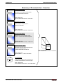
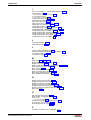
Summary of Documentation - Overview
Functional Description:
Description of all implemented Function
based on SERCOS-Parameters
Order designation:
DOK-ECODR3-MGP-01VRS**-FK01-EN-P
Parameter Description:
A description of all parameters
used in the firmware
Order designation:
DOK-ECODR3-MGP-01VRS**-PA01-EN-P
Troubleshooting Guide:
-Explanation of the diagnostic states
-How to proceed when eliminating faults
Order designation:
DOK-ECODR3-MGP-01VRS**-WA01-EN-P
Firmware Version Notes:
Description of new and changed functions
in terms of the derivatives:
FWA-ECODR3-MGP-01VRS-MS
Order designation:
DOK-ECODR3-***-**VRS**-FV01-EN-P
CD: DRIVEHELP
(6-:),)04
Collection of Windows help systems which
contains documentation on firmware types
Order designation:
DOK-GENERL-DRIVEHELP**-GExx-MS-D0600
DOK-ECODR3-MGP-01VRS**-WA01-EN-P
Order designation
DOK-ECODR3-MGP-01VRS**-7401-EN-P
About this Documentation
Ecodrive Cs
Notes
DOK-ECODR3-MGP-01VRS**-WA01-EN-P
Contents I
Ecodrive Cs
Contents
1
Diagnostic Message Descriptions
1-1
Overview of the Diagnostic Message Descriptions ................................................................................. 1-1
Diagnostic Message Types...................................................................................................... 1-1
Construction of a Diagnostic Message .................................................................................... 1-1
H1-Display................................................................................................................................ 1-2
2
Important Directions for Use
2.1
2-1
Appropriate Use ............................................................................................................................. 2-1
Introduction .............................................................................................................................. 2-1
Inappropriate Use .................................................................................................................... 2-2
3
Safety Instructions for Electric Drives and Controls
3-1
3.1
Introduction..................................................................................................................................... 3-1
3.2
Explanations................................................................................................................................... 3-1
3.3
Hazards by Improper Use .............................................................................................................. 3-2
3.4
General Information ....................................................................................................................... 3-3
3.5
Protection Against Contact with Electrical Parts ............................................................................ 3-5
3.6
Protection Against Electric Shock by Protective Low Voltage (PELV)........................................... 3-6
3.7
Protection Against Dangerous Movements.................................................................................... 3-7
3.8
Protection Against Magnetic and Electromagnetic Fields During Operation and Mounting .......... 3-9
3.9
Protection Against Contact with Hot Parts ..................................................................................... 3-9
3.10 Protection During Handling and Mounting ..................................................................................... 3-9
3.11 Battery Safety............................................................................................................................... 3-10
3.12 Protection Against Pressurized Systems ..................................................................................... 3-11
4
Description of Diagnostic Messages F… and E…
4.1
4-1
Error Diagnostic Messages F… ..................................................................................................... 4-1
F205 Cam shaft invalid ............................................................................................................ 4-2
Switching to uninitialized operation mode................................................................................ 4-2
F208 UL The motor type has changed. ................................................................................... 4-2
F209 PL Load parameter default values.................................................................................. 4-3
F218 Amplifier overtemperature shutdown.............................................................................. 4-3
F219 Motor overtemperature shutdown................................................................................... 4-4
F220 Braking resistor overload shutdown ............................................................................... 4-4
F223 Error during initialisation of the parking axis................................................................... 4-5
F224 Maximum braking time exceeded................................................................................... 4-5
F226 Undervoltage in power section ....................................................................................... 4-6
F228 Excessive deviation ........................................................................................................ 4-6
DOK-ECODR3-MGP-01VRS**-WA01-EN-P
II Contents
Ecodrive Cs
F237 Excessive position command difference ........................................................................ 4-6
F248 Low battery voltage......................................................................................................... 4-7
F250 Overflow of target position preset memory..................................................................... 4-8
F253 Incr. encoder emulator: pulse frequency too high .......................................................... 4-8
F260 Command current limit shutoff........................................................................................ 4-8
F262 External short at status outputs ...................................................................................... 4-9
F267 Erroneous internal hardware synchronization ................................................................ 4-9
F269 Error during release of the motor holding brake............................................................. 4-9
F276 Absolute encoder out of allowed window ..................................................................... 4-10
F277 Current measurement trim wrong................................................................................. 4-10
F281 Mains fault .................................................................................................................... 4-10
F401 Double MST failure shutdown ...................................................................................... 4-11
F402 Double MDT failure shutdown ...................................................................................... 4-11
F403 Invalid communication phase shutdown....................................................................... 4-12
F404 Error during phase progression .................................................................................... 4-12
F405 Error during phase regression ...................................................................................... 4-12
F406 Phase switching without ready signal........................................................................... 4-12
F407 Error during initialization of master communication...................................................... 4-13
F408 Fatal error of the interface card .................................................................................... 4-13
F409 Bus failure..................................................................................................................... 4-13
F410 Synchronization with field bus impossible .................................................................... 4-14
F434 Emergency-Stop ........................................................................................................... 4-14
F629 Positive travel limit exceeded ....................................................................................... 4-14
F630 Negative travel limit exceeded...................................................................................... 4-15
F634 Emergency-Stop ........................................................................................................... 4-16
F643 Positive travel limit switch detected .............................................................................. 4-16
F644 Negative travel limit switch detected ............................................................................ 4-16
F811 Commutation offset could not be determined............................................................... 4-17
F812 Motion range exceeded during commutation ............................................................... 4-17
F818 Amplifier overtemperature shutdown............................................................................ 4-18
F822 Encoder 1 failure: signal amplitude wrong.................................................................... 4-18
F825 Overvoltage in power section ....................................................................................... 4-20
F860 Overcurrent: short in power stage ................................................................................ 4-20
F870 +24Volt DC error........................................................................................................... 4-20
F878 Velocity loop error......................................................................................................... 4-21
F879 Velocity limit S-0-0091 exceeded ................................................................................. 4-22
4.2
Warning Diagnostic Messages E… ............................................................................................. 4-23
E225 Motor overload.............................................................................................................. 4-24
E226 Undervoltage in power section ..................................................................................... 4-24
E247 Interpolation velocity = 0............................................................................................... 4-24
E248 Interpolation acceleration = 0 ....................................................................................... 4-25
E249 Positioning velocity >= S-0-0091.................................................................................. 4-25
E250 Amplifier overtemp. prewarning.................................................................................... 4-26
E251 Motor overtemp. prewarning ........................................................................................ 4-26
E252 Braking resistor overload prewarning........................................................................... 4-26
E253 Target position out of travel range................................................................................ 4-27
DOK-ECODR3-MGP-01VRS**-WA01-EN-P
Contents III
Ecodrive Cs
E254 Not homed .................................................................................................................... 4-27
E255 Feedrate-override S-0-0108 = 0 ................................................................................... 4-28
E256 Torque limit = 0............................................................................................................. 4-28
E257 Continuous current limit active ..................................................................................... 4-28
E258 Selected process block is not programmed. ................................................................ 4-29
E259 Command velocity limit active ...................................................................................... 4-29
E260 Command Current limit active ...................................................................................... 4-29
E261 Continuous current limit pre-warning............................................................................ 4-30
E263 Velocity command value > limit S-0-0091 .................................................................... 4-30
E264 Target position out of num. range ................................................................................ 4-30
E269 Brake torque too low..................................................................................................... 4-31
E281 Mains fault .................................................................................................................... 4-31
E401 Error in the parameter channel..................................................................................... 4-32
E402 Error in the cyclic data channel .................................................................................... 4-32
E405 No data exchange possible via the field bus ................................................................ 4-32
E408 Invalid addressing of MDT-data container A ................................................................ 4-32
E409 Invalid addressing of AT-data container A ................................................................... 4-33
E410 Slave not scanned or address 0................................................................................... 4-33
E825 Overvoltage in power stage.......................................................................................... 4-33
E826 Undervoltage in power section ..................................................................................... 4-34
E829 Positive position limit exceeded ................................................................................... 4-34
E830 Negative position limit exceeded.................................................................................. 4-34
E831 Position limit reached during jog .................................................................................. 4-35
E834 Emergency-Stop........................................................................................................... 4-35
E835 Quick stop with probe detection is active ..................................................................... 4-35
E843 Positive limit switch activated ....................................................................................... 4-36
E844 Negative limit switch activated ..................................................................................... 4-36
E881 Mains fault .................................................................................................................... 4-36
5
Description of Diagnostic Messages B…, C…, D… and A…
5-1
Command Diagnostic Messages B…, C… and D… ............................................................................... 5-1
B100 Command Release motor holding brake........................................................................ 5-2
B101 Command not enabled ................................................................................................... 5-2
B200 Brake check command................................................................................................... 5-2
B201 Brake check only with drive enable ................................................................................ 5-2
B202 Error during abrasion of the brake.................................................................................. 5-2
B203 Brake torque too low....................................................................................................... 5-3
C100 Communication phase 3 transition check ...................................................................... 5-3
C101 Invalid communication parameter (S-0-0021) ................................................................ 5-3
C102 Limit error communication parameter (S-0-0021) .......................................................... 5-3
C104 Config. IDN for MDT not configurable ............................................................................ 5-4
C105 Configurated length > max. length for MDT ................................................................... 5-4
C106 Config. IDN for AT not configurable ............................................................................... 5-4
C107 Configurated length > max. length for AT ...................................................................... 5-5
C108 Time slot parameter > Sercos cycle time....................................................................... 5-5
C109 Position of data record in MDT (S-0-0009) even ........................................................... 5-6
DOK-ECODR3-MGP-01VRS**-WA01-EN-P
IV Contents
Ecodrive Cs
C110 Length of MDT (S-0-0010) odd ...................................................................................... 5-6
C111 ID9 + Record length - 1 > length MDT (S-0-0010)......................................................... 5-6
C112 TNcyc (S-0-0001) or TScyc (S-0-0002) error................................................................. 5-6
C113 Relation TNcyc (S-0-0001) to TScyc (S-0-0002) error................................................... 5-7
C114 T4 > TScyc (S-0-0002) - T4min (S-0-0005) ................................................................... 5-7
C115 T2 too small.................................................................................................................... 5-7
C118 Order of MDT configuration wrong................................................................................. 5-8
C200 Communication phase 4 transition check ...................................................................... 5-8
C201 Invalid parameter(s) (->S-0-0022).................................................................................. 5-8
C202 Parameter limit error (->S-0-0022) ................................................................................. 5-8
C203 Parameter calculation error (->S-0-0022) ...................................................................... 5-9
C204 Motor type P-0-4014 incorrect........................................................................................ 5-9
C211 Invalid feedback data (->S-0-0022)................................................................................ 5-9
C212 Invalid amplifier data (->S-0-0022)............................................................................... 5-10
C213 Position data scaling error............................................................................................ 5-10
C214 Velocity data scaling error ............................................................................................ 5-11
C215 Acceleration data scaling error..................................................................................... 5-11
C216 Torque/force data scaling error .................................................................................... 5-12
C217 Feedback1 data reading error...................................................................................... 5-12
C220 Feedback 1 initializing error ......................................................................................... 5-12
C223 Input value for max. range too high.............................................................................. 5-13
C227 Modulo range error....................................................................................................... 5-13
C228 Controller type S-0-0140 wrong ................................................................................... 5-13
C234 Encoder combination not possible ............................................................................... 5-13
C236 Feedback 1 required (P-0-0074) .................................................................................. 5-14
C243 Motor-amplifier combination invalid.............................................................................. 5-14
C300 Command Set absolute measuring.............................................................................. 5-14
C302 Absolute measuring system not installed..................................................................... 5-14
C400 Switching to parameter mode ...................................................................................... 5-15
C401 Drive active, switching not allowed .............................................................................. 5-15
C402 Only allowed without master ........................................................................................ 5-15
C500 Reset class 1 diagnostic, error reset............................................................................ 5-15
C600 Drive controlled homing procedure command ............................................................. 5-16
C601 Homing only possible with drive enable ....................................................................... 5-16
C602 Distance home switch - reference mark erroneous ..................................................... 5-16
C604 Homing of absolute encoder not possible .................................................................... 5-16
C606 Reference mark not detected....................................................................................... 5-17
C700 Basic load..................................................................................................................... 5-17
C702 Default parameters not available ................................................................................. 5-17
C703 Default parameters invalid ........................................................................................... 5-18
C704 Parameters not copyable ............................................................................................. 5-18
C800 Default parameter load................................................................................................. 5-18
C801 Parameter default value erroneous (-> S-0-0021) ....................................................... 5-18
C802 Locked with password .................................................................................................. 5-19
D300 Command adjust commutation .................................................................................... 5-19
D301 Drive not ready for commutation command ................................................................. 5-19
DOK-ECODR3-MGP-01VRS**-WA01-EN-P
Contents V
Ecodrive Cs
D302 Torque/Force too small to move .................................................................................. 5-19
D303 Drive in control at start of command ............................................................................ 5-20
D304 Error in offset calculation.............................................................................................. 5-20
D305 Drive enable refused .................................................................................................... 5-20
D306 Power is off................................................................................................................... 5-20
D307 Drive does not move .................................................................................................... 5-20
D308 No adjustment with asynchronous motor ..................................................................... 5-20
D309 Proceed to phase 4 ...................................................................................................... 5-20
D310 Input master password ................................................................................................. 5-20
D311 Commutation offset could not be determined. ............................................................. 5-21
D312 Motion range exceeded during commutation ............................................................... 5-21
D400 Positive stop drive procedure command ...................................................................... 5-22
D401 ZKL1-Error at command start....................................................................................... 5-22
D500 Command Get mark position ....................................................................................... 5-22
D501 Incremental encoder required ...................................................................................... 5-22
D600 Cancel reference point procedure command............................................................... 5-23
D700 Parking axis command................................................................................................. 5-23
D701 Parking axis only while drive is disabled ...................................................................... 5-23
D900 Command automatic loop tuning ................................................................................. 5-23
D901 Start requires drive enable ........................................................................................... 5-24
D902 Motor feedback data not valid ...................................................................................... 5-24
D903 Inertia detection failed .................................................................................................. 5-25
D904 Gain adjustment failed.................................................................................................. 5-25
D905 Travel range invalid, P-0-0166 & P-0-0167.................................................................. 5-25
D906 Travel range exceeded................................................................................................. 5-26
5.1
Status Diagnostic Messages A…................................................................................................. 5-27
A000 Communication phase 0............................................................................................... 5-27
A001 Communication phase 1............................................................................................... 5-27
A002 Communication phase 2............................................................................................... 5-27
A003 Communication phase 3............................................................................................... 5-28
A009 Automatic baud rate detection for SERCOS Interface ................................................. 5-28
A010 Drive HALT ................................................................................................................... 5-29
A012 Control and power sections ready for operation .......................................................... 5-29
A013 Ready for power on ...................................................................................................... 5-29
A100 Drive in TORQUE control ............................................................................................. 5-29
A101 Drive in VELOCITY control........................................................................................... 5-29
A102 Position mode with encoder 1 ...................................................................................... 5-30
A104 Position mode lagless, encoder 1 ................................................................................ 5-30
A106 Drive controlled interpolation, encoder 1...................................................................... 5-30
A108 Drive controlled interpolation, lagless, encoder 1 ........................................................ 5-30
A110 Velocity synchronization, virtual master drive .............................................................. 5-31
A112 Phase synchronization, encoder 1, virtual master drive............................................... 5-31
A116 Phase synchr. lagless, encoder 1, virtual master drive................................................ 5-31
A128 Cam shaft, encoder 1, virtual master drive................................................................... 5-31
A132 Cam shaft, lagless, encoder 1, virt. master drive ......................................................... 5-32
A150 Drive controlled positioning, encoder 1 ........................................................................ 5-32
DOK-ECODR3-MGP-01VRS**-WA01-EN-P
VI Contents
Ecodrive Cs
A151 Drive controlled positioning, encoder 1, lagless........................................................... 5-32
A206 Process block mode, encoder 1 ................................................................................... 5-33
A207 Process block mode lagless, encoder 1....................................................................... 5-33
A208 JOG mode positive ....................................................................................................... 5-33
A218 JOG mode negative...................................................................................................... 5-33
A400 Automatic drive check and adjustment......................................................................... 5-33
A401 Drive deceleration to standstill ..................................................................................... 5-34
A800 Unknown operating mode ............................................................................................ 5-34
6
Index
6-1
7
Service & Support
7-1
7.1
Helpdesk ........................................................................................................................................ 7-1
7.2
Service-Hotline............................................................................................................................... 7-1
7.3
Internet ........................................................................................................................................... 7-1
7.4
Vor der Kontaktaufnahme... - Before contacting us....................................................................... 7-1
7.5
Kundenbetreuungsstellen - Sales & Service Facilities .................................................................. 7-2
DOK-ECODR3-MGP-01VRS**-WA01-EN-P
Diagnostic Message Descriptions 1-1
Ecodrive Cs
1
Diagnostic Message Descriptions
Overview of the Diagnostic Message Descriptions
Diagnostic Message Types
Each operational state of the drive will be characterized with a diagnostic
message.
Differentiations will be made between:
• Error diagnostic messages
• Warning diagnostic messages
• Command diagnostic messages
• Drive mode diagnostic messages
• Operation status
Construction of a Diagnostic Message
A diagnostic message consists of:
• Diagnostic message number
• Diagnostic text
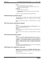
F228 Excessive deviation
diagnostic message
diagnostic message number
Fig. 1-1:
Diagnostic message with a diagnostic message number and text
For the example in the graphic, "F2" and "28" are shown alternately on the
H1-Display.
The control system can read out the diagnostic number in hexadecimal
form in parameter S-0-0390, Diagnostic message number.
In addition, the drive provides to the control system the diagnostic number
and diagnostic text as a string F228 Excessive deviation in parameter
S-0-0095, Diagnostic message.
DOK-ECODR3-MGP-01VRS**-WA01-EN-P
1-2 Diagnostic Message Descriptions
Ecodrive Cs
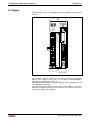
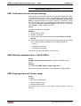
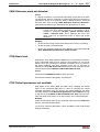
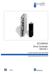
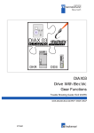
H1-Display
The H1-Display serves as an optical display of the diagnostic message on
the drive.
Rexroth
ADDRESS
S2
S3
9 0 1
9 0 1
7 8
4 5 6
Cs
4 5 6
H1
ECODRIVE
2 3
2 3
7 8
NODE
LINE ERROR
X6
X1
INPUTíF200V-240V
TX
X20
RX
X21
S20
2
1
ON
X2
DL2
X5_1
DL1
L2C
L1C
L3
L2
X6
L1
S1
X5_3
X3
X4
W
V
U
X5_2
RB2
RB3
RB1
X5
X4
frontansicht.fh7
Fig. 1-2:
H1-Display
The diagnostic number appears on this two-positional seven-segment
display. The image can be seen on the figure "Priority-dependent
diagnostic message display" (Fig. 1-3).
This display quickly shows the current operation status without the use of
a communications interface.
The operating mode cannot be seen from the H1-Display. If the drive
follows the operating mode and no command was activated, then the
symbol "AF" appears on the display.
DOK-ECODR3-MGP-01VRS**-WA01-EN-P
Diagnostic Message Descriptions 1-3
Ecodrive Cs
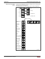
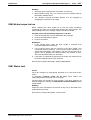
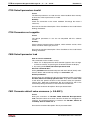
Diagnostic Message Output
Priority
If more than one diagnostic message is waiting, then the message with
the highest priority will be displayed.
The following graphic classifies operation status in order of importance.
error
P
R
warning
I
O
R
command error
I
T
command active
Y
Ready for operation?
yes
no
drive interlock
active
communication phase
ready for
operation
drive
ready
drive check +
adjustment
drive
shutdown
drive
halt
drive is following
operating mode
drive macro
moves drive
basic load
required
parameter
loading
jogging: drive
moves backward
jogging: drive
moves forward
Da0003f1.fh7
Fig. 1-3:
DOK-ECODR3-MGP-01VRS**-WA01-EN-P
Priority-dependent diagnostic message display
1-4 Diagnostic Message Descriptions
Ecodrive Cs
Clear Coded Diagnostic Message
The clear coded diagnostic message contains the diagnostic message
number followed by the diagnostic text, as shown in the example
"Excessive deviation" (Fig. 1-1).
It can be read out with parameter S-0-0095, Diagnostic message and
directly displays the operation status on an operator surface.
The clear coded diagnostic message will be switched to the current
language.
DOK-ECODR3-MGP-01VRS**-WA01-EN-P
Important Directions for Use 2-1
Ecodrive Cs
2
Important Directions for Use
2.1
Appropriate Use
Introduction
Rexroth Indramat products represent state-of-the-art developments and
manufacturing. They are tested prior to delivery to ensure operating safety
and reliability.
The products may only be used in the manner that is defined as
appropriate. If they are used in an inappropriate manner, then situations
can develop that may lead to property damage or injury to personnel.
Note:
Rexroth Indramat, as manufacturer, is not liable for any
damages resulting from inappropriate use. In such cases, the
guarantee and the right to payment of damages resulting from
inappropriate use are forfeited. The user alone carries all
responsibility of the risks.
Before using Rexroth Indramat products, make sure that all the prerequisites for an appropriate use of the products are satisfied:
• Personnel that in any way, shape or form uses our products must first
read and understand the relevant safety instructions and be familiar
with appropriate use.
• If the product takes the form of hardware, then they must remain in
their original state, in other words, no structural changes are permitted.
It is not permitted to decompile software products or alter source
codes.
• Do not mount damaged or faulty products or use them in operation.
• Make sure that the products have been installed in the manner
described in the relevant documentation.
DOK-ECODR3-MGP-01VRS**-WA01-EN-P
2-2 Important Directions for Use
Ecodrive Cs
• Areas of Use and Application
Drive controllers made by Rexroth Indramat are designed to control
electrical motors and monitor their operation.
Control and monitoring of the motors may require additional sensors and
actors.
Note:
The drive controllers may only be used with the accessories
and parts specified in this document. If a component has not
been specifically named, then it may not be either mounted or
connected. The same applies to cables and lines.
Operation is only permitted in the specified configurations and
combinations of components using the software and firmware
as specified in the relevant function descriptions.
Every drive controller has to be programmed before starting it up, making
it possible for the motor to execute the specific functions of an application.
The drive controllers of the ECODRIVE03 family are designed for use in
single or multiple-axis drive and control applications.
To ensure an application-specific use, the drive controllers are available
with differing drive power and different interfaces.
Typical applications of drive controllers belonging to the ECODRIVE03
family are:
• handling and mounting systems,
• packaging and foodstuff machines,
• printing and paper processing machines and
• machine tools.
The drive controllers may only be operated under the assembly,
installation and ambient conditions as described here (temperature,
system of protection, humidity, EMC requirements, etc.) and in the
position specified.
Inappropriate Use
Using the drive controllers outside of the above-referenced areas of
application or under operating conditions other than described in the
document and the technical data specified is defined as “inappropriate
use".
Drive controllers may not be used if
• they are subject to operating conditions that do not meet the above
specified ambient conditions. This includes, for example, operation
under water, in the case of extreme temperature fluctuations or
extremely high maximum temperatures or if
• Rexroth Indramat has not specifically released them for that intended
purpose. Please note the specifications outlined in the general safety
instructions!
DOK-ECODR3-MGP-01VRS**-WA01-EN-P
Safety Instructions for Electric Drives and Controls 3-1
Ecodrive Cs
3
Safety Instructions for Electric Drives and Controls
3.1
Introduction
Read these instructions before the initial startup of the equipment in order
to eliminate the risk of bodily harm or material damage. Follow these
safety instructions at all times.
Do not attempt to install or start up this equipment without first reading all
documentation provided with the product. Read and understand these
safety instructions and all user documentation of the equipment prior to
working with the equipment at any time. If you do not have the user
documentation for your equipment, contact your local Rexroth Indramat
representative to send this documentation immediately to the person or
persons responsible for the safe operation of this equipment.
If the equipment is resold, rented or transferred or passed on to others,
then these safety instructions must be delivered with the equipment.
WARNING
3.2
Improper use of this equipment, failure to follow
the safety instructions in this document or
tampering with the product, including disabling
of safety devices, may result in material
damage, bodily harm, electric shock or even
death!
Explanations
The safety instructions describe the following degrees of hazard
seriousness in compliance with ANSI Z535. The degree of hazard
seriousness informs about the consequences resulting from noncompliance with the safety instructions.
Warning symbol with signal
word
Degree of hazard seriousness according
to ANSI
Death or severe bodily harm will occur.
DANGER
Death or severe bodily harm may occur.
WARNING
Bodily harm or material damage may occur.
CAUTION
Fig. 3-1:
DOK-ECODR3-MGP-01VRS**-WA01-EN-P
Hazard classification (according to ANSI Z535)
3-2 Safety Instructions for Electric Drives and Controls
3.3
Ecodrive Cs
Hazards by Improper Use
High voltage and high discharge current!
Danger to life or severe bodily harm by electric
shock!
DANGER
Dangerous movements! Danger to life, severe
bodily harm or material damage by
unintentional motor movements!
DANGER
High electrical voltage due to wrong
connections! Danger to life or bodily harm by
electric shock!
WARNING
Health hazard for persons with heart
pacemakers, metal implants and hearing aids in
proximity to electrical equipment!
WARNING
Surface of machine housing could be extremely
hot! Danger of injury! Danger of burns!
CAUTION
CAUTION
Risk of injury due to improper handling! Bodily
harm caused by crushing, shearing, cutting and
mechanical shock or incorrect handling of
pressurized systems!
Risk of injury due to incorrect handling of
batteries!
CAUTION
DOK-ECODR3-MGP-01VRS**-WA01-EN-P
Safety Instructions for Electric Drives and Controls 3-3
Ecodrive Cs
3.4
General Information
Rexroth Indramat GmbH is not liable for damages resulting from failure to
observe the warnings provided in this documentation.
Read the operating, maintenance and safety instructions in your language
before starting up the machine. If you find that you cannot completely
understand the documentation for your product, please ask your
supplier to clarify.
Proper and correct transport, storage, assembly and installation as well
as care in operation and maintenance are prerequisites for optimal
and safe operation of this equipment.
Only persons who are trained and qualified for the use and operation of
the equipment may work on this equipment or within its proximity.
The persons are qualified if they have sufficient knowledge of the
assembly, installation and operation of the equipment as well as an
understanding of all warnings and precautionary measures noted in
these instructions.
Furthermore, they must be trained, instructed and qualified to switch
electrical circuits and equipment on and off in accordance with
technical safety regulations, to ground them and to mark them
according to the requirements of safe work practices. They must
have adequate safety equipment and be trained in first aid.
Only use spare parts and accessories approved by the manufacturer.
Follow all safety regulations and requirements for the specific application
as practiced in the country of use.
The equipment is designed for installation in industrial machinery.
The ambient conditions given in the product documentation must be
observed.
Use only safety features and applications that are clearly and explicitly
approved in the Project Planning Manual.
For example, the following areas of use are not permitted: construction
cranes, elevators used for people or freight, devices and vehicles to
transport people, medical applications, refinery plants, transport of
hazardous goods, nuclear applications, applications sensitive to high
frequency, mining, food processing, control of protection equipment
(also in a machine).
The information given in the documentation of the product with regard to
the use of the delivered components contains only examples of
applications and suggestions.
The machine and installation manufacturer must
make sure that the delivered components are suited for his individual
application and check the information given in this documentation
with regard to the use of the components,
make sure that his application complies with the applicable safety
regulations and standards and carry out the required measures,
modifications and complements.
Startup of the delivered components is only permitted once it is sure that
the machine or installation in which they are installed complies with the
national regulations, safety specifications and standards of the
application.
DOK-ECODR3-MGP-01VRS**-WA01-EN-P
3-4 Safety Instructions for Electric Drives and Controls
Ecodrive Cs
Operation is only permitted if the national EMC regulations for the
application are met.
The instructions for installation in accordance with EMC requirements
can be found in the documentation "EMC in Drive and Control
Systems".
The machine or installation manufacturer is responsible for
compliance with the limiting values as prescribed in the national
regulations.
Technical data, connections and operational conditions are specified in
the product documentation and must be followed at all times.
DOK-ECODR3-MGP-01VRS**-WA01-EN-P
Safety Instructions for Electric Drives and Controls 3-5
Ecodrive Cs
3.5
Protection Against Contact with Electrical Parts
Note:
This section refers to equipment and drive components with
voltages above 50 Volts.
Touching live parts with voltages of 50 Volts and more with bare hands or
conductive tools or touching ungrounded housings can be dangerous and
cause electric shock. In order to operate electrical equipment, certain
parts must unavoidably have dangerous voltages applied to them.
High electrical voltage! Danger to life, severe
bodily harm by electric shock!
DANGER
DOK-ECODR3-MGP-01VRS**-WA01-EN-P
Only those trained and qualified to work with or on
electrical equipment are permitted to operate, maintain
or repair this equipment.
Follow general construction and safety regulations when
working on high voltage installations.
Before switching on power the ground wire must be
permanently connected to all electrical units according
to the connection diagram.
Do not operate electrical equipment at any time, even for
brief measurements or tests, if the ground wire is not
permanently connected to the points of the components
provided for this purpose.
Before working with electrical parts with voltage higher than
50 V, the equipment must be disconnected from the
mains voltage or power supply. Make sure the
equipment cannot be switched on again unintended.
The following should be observed with electrical drive and
filter components:
Wait five (5) minutes after switching off power to allow
capacitors to discharge before beginning to work.
Measure the voltage on the capacitors before beginning
to work to make sure that the equipment is safe to
touch.
Never touch the electrical connection points of a
component while power is turned on.
Install the covers and guards provided with the equipment
properly before switching the equipment on. Prevent
contact with live parts at any time.
A residual-current-operated protective device (RCD) must
not be used on electric drives! Indirect contact must be
prevented by other means, for example, by an
overcurrent protective device.
Electrical components with exposed live parts and
uncovered high voltage terminals must be installed in a
protective housing, for example, in a control cabinet.
3-6 Safety Instructions for Electric Drives and Controls
Ecodrive Cs
To be observed with electrical drive and filter components:
High electrical voltage on the housing!
High leakage current! Danger to life, danger of
injury by electric shock!
DANGER
3.6
Connect the electrical equipment, the housings of all
electrical units and motors permanently with the safety
conductor at the ground points before power is
switched on. Look at the connection diagram. This is
even necessary for brief tests.
Connect the safety conductor of the electrical equipment
always permanently and firmly to the supply mains.
Leakage current exceeds 3.5 mA in normal operation.
Use a copper conductor with at least 10 mm² cross
section over its entire course for this safety conductor
connection!
Prior to startups, even for brief tests, always connect the
protective conductor or connect with ground wire.
Otherwise, high voltages can occur on the housing
that lead to electric shock.
Protection Against Electric Shock by Protective Low
Voltage (PELV)
All connections and terminals with voltages between 0 and 50 Volts on
Rexroth Indramat products are protective low voltages designed in
accordance with international standards on electrical safety.
High electrical voltage due to wrong
connections! Danger to life, bodily harm by
electric shock!
WARNING
Only connect equipment, electrical components and
cables of the protective low voltage type (PELV =
Protective Extra Low Voltage) to all terminals and
clamps with voltages of 0 to 50 Volts.
Only electrical circuits may be connected which are safely
isolated against high voltage circuits. Safe isolation is
achieved, for example, with an isolating transformer,
an opto-electronic coupler or when battery-operated.
DOK-ECODR3-MGP-01VRS**-WA01-EN-P
Ecodrive Cs
3.7
Safety Instructions for Electric Drives and Controls 3-7
Protection Against Dangerous Movements
Dangerous movements can be caused by faulty control of the connected
motors. Some common examples are:
improper or wrong wiring of cable connections
incorrect operation of the equipment components
wrong input of parameters before operation
malfunction of sensors, encoders and monitoring devices
defective components
software or firmware errors
Dangerous movements can occur immediately after equipment is
switched on or even after an unspecified time of trouble-free operation.
The monitoring in the drive components will normally be sufficient to avoid
faulty operation in the connected drives. Regarding personal safety,
especially the danger of bodily injury and material damage, this alone
cannot be relied upon to ensure complete safety. Until the integrated
monitoring functions become effective, it must be assumed in any case
that faulty drive movements will occur. The extent of faulty drive
movements depends upon the type of control and the state of operation.
DOK-ECODR3-MGP-01VRS**-WA01-EN-P
3-8 Safety Instructions for Electric Drives and Controls
Ecodrive Cs
Dangerous movements! Danger to life, risk of
injury, severe bodily harm or material damage!
DANGER
Ensure personal safety by means of qualified and tested
higher-level monitoring devices or measures
integrated in the installation. Unintended machine
motion is possible if monitoring devices are disabled,
bypassed or not activated.
Pay attention to unintended machine motion or other
malfunction in any mode of operation.
Keep free and clear of the machine’s range of motion and
moving parts. Possible measures to prevent people
from accidentally entering the machine’s range of
motion:
- use safety fences
- use safety guards
- use protective coverings
- install light curtains or light barriers
Fences and coverings must be strong enough to resist
maximum possible momentum, especially if there is a
possibility of loose parts flying off.
Mount the emergency stop switch in the immediate reach
of the operator. Verify that the emergency stop works
before startup. Don’t operate the machine if the
emergency stop is not working.
Isolate the drive power connection by means of an
emergency stop circuit or use a starting lockout to
prevent unintentional start.
Make sure that the drives are brought to a safe standstill
before accessing or entering the danger zone. Safe
standstill can be achieved by switching off the power
supply contactor or by safe mechanical locking of
moving parts.
Secure vertical axes against falling or dropping after
switching off the motor power by, for example:
- mechanically securing the vertical axes
- adding an external braking/ arrester/ clamping
mechanism
- ensuring sufficient equilibration of the vertical axes
The standard equipment motor brake or an external
brake controlled directly by the drive controller are
not sufficient to guarantee personal safety!
Disconnect electrical power to the equipment using a
master switch and secure the switch against
reconnection for:
- maintenance and repair work
- cleaning of equipment
- long periods of discontinued equipment use
Prevent the operation of high-frequency, remote control
and radio equipment near electronics circuits and
supply leads. If the use of such equipment cannot be
avoided, verify the system and the installation for
possible malfunctions in all possible positions of
normal use before initial startup. If necessary, perform
a special electromagnetic compatibility (EMC) test on
the installation.
DOK-ECODR3-MGP-01VRS**-WA01-EN-P
Safety Instructions for Electric Drives and Controls 3-9
Ecodrive Cs
3.8
Protection Against Magnetic and Electromagnetic Fields
During Operation and Mounting
Magnetic and electromagnetic fields generated near current-carrying
conductors and permanent magnets in motors represent a serious health
hazard to persons with heart pacemakers, metal implants and hearing
aids.
Health hazard for persons with heart
pacemakers, metal implants and hearing aids in
proximity to electrical equipment!
WARNING
3.9
Persons with heart pacemakers, hearing aids and metal
implants are not permitted to enter the following
areas:
- Areas in which electrical equipment and parts are
mounted, being operated or started up.
- Areas in which parts of motors with permanent
magnets are being stored, operated, repaired or
mounted.
If it is necessary for a person with a heart pacemaker to
enter such an area, then a doctor must be consulted
prior to doing so. Heart pacemakers that are already
implanted or will be implanted in the future, have a
considerable variation in their electrical noise
immunity. Therefore there are no rules with general
validity.
Persons with hearing aids, metal implants or metal
pieces must consult a doctor before they enter the
areas described above. Otherwise, health hazards will
occur.
Protection Against Contact with Hot Parts
Housing surfaces could be extremely hot!
Danger of injury! Danger of burns!
CAUTION
Do not touch housing surfaces near sources of heat!
Danger of burns!
After switching the equipment off, wait at least ten (10)
minutes to allow it to cool down before touching it.
Do not touch hot parts of the equipment, such as
housings with integrated heat sinks and resistors.
Danger of burns!
3.10 Protection During Handling and Mounting
Under certain conditions, incorrect handling and mounting of parts and
components may cause injuries.
DOK-ECODR3-MGP-01VRS**-WA01-EN-P
3-10 Safety Instructions for Electric Drives and Controls
Ecodrive Cs
Risk of injury by incorrect handling! Bodily
harm caused by crushing, shearing, cutting and
mechanical shock!
CAUTION
Observe general installation and safety instructions with
regard to handling and mounting.
Use appropriate mounting and transport equipment.
Take precautions to avoid pinching and crushing.
Use only appropriate tools. If specified by the product
documentation, special tools must be used.
Use lifting devices and tools correctly and safely.
For safe protection wear appropriate protective clothing,
e.g. safety glasses, safety shoes and safety gloves.
Never stand under suspended loads.
Clean up liquids from the floor immediately to prevent
slipping.
3.11 Battery Safety
Batteries contain reactive chemicals in a solid housing. Inappropriate
handling may result in injuries or material damage.
Risk of injury by incorrect handling!
CAUTION
Note:
Do not attempt to reactivate discharged batteries by
heating or other methods (danger of explosion and
cauterization).
Never charge non-chargeable batteries (danger of
leakage and explosion).
Never throw batteries into a fire.
Do not dismantle batteries.
Do not damage electrical components installed in the
equipment.
Be aware of environmental protection and disposal! The
batteries contained in the product should be considered as
hazardous material for land, air and sea transport in the sense
of the legal requirements (danger of explosion). Dispose
batteries separately from other waste. Observe the legal
requirements in the country of installation.
DOK-ECODR3-MGP-01VRS**-WA01-EN-P
Safety Instructions for Electric Drives and Controls 3-11
Ecodrive Cs
3.12 Protection Against Pressurized Systems
Certain motors and drive controllers, corresponding to the information in
the respective Project Planning Manual, must be provided with
pressurized media, such as compressed air, hydraulic oil, cooling fluid
and cooling lubricant supplied by external systems. Incorrect handling of
the supply and connections of pressurized systems can lead to injuries or
accidents. In these cases, improper handling of external supply systems,
supply lines or connections can cause injuries or material damage.
Danger of injury by incorrect handling of
pressurized systems !
CAUTION
Note:
DOK-ECODR3-MGP-01VRS**-WA01-EN-P
Do not attempt to disassemble, to open or to cut a
pressurized system (danger of explosion).
Observe the operation instructions of the respective
manufacturer.
Before disassembling pressurized systems, release
pressure and drain off the fluid or gas.
Use suitable protective clothing (for example safety
glasses, safety shoes and safety gloves)
Remove any fluid that has leaked out onto the floor
immediately.
Environmental protection and disposal! The media used in the
operation of the pressurized system equipment may not be
environmentally compatible. Media that are damaging the
environment must be disposed separately from normal waste.
Observe the legal requirements in the country of installation.
3-12 Safety Instructions for Electric Drives and Controls
Ecodrive Cs
Notes
DOK-ECODR3-MGP-01VRS**-WA01-EN-P
Description of Diagnostic Messages F… and E… 4-1
Ecodrive Cs
4
Description of Diagnostic Messages F… and E…
4.1
Error Diagnostic Messages F…
Many functions are monitored subject to operating modes and parameter
settings. An error message is generated if a condition is discovered which
no longer allows proper operation.
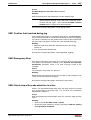
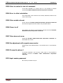
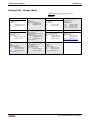
Error Classes
The errors are separated into four different error classes. The error class
is evident from the diagnostic message. They are determined with the
drive’s error response.
Error class
Diagnostic
message
Drive reaction
Fatal
F8xx
Torque free switching
Travel range
F6xx
Speed command value-zero switch
Interface
F4xx
In accordance with "Best possible
deceleration"
Non-fatal
F2xx
In accordance with "Best possible
deceleration"
Fig. 4-1:
Drive’s Error Reaction
Error classes and drive reaction
If an error state is detected in the drive then an automatic operation of the
drive’s error response will be started as long the drive is in control. The
H1-Display blinks a Fx / xx.
The drive’s reaction can be parameterized by P-0-0119, Best possible
deceleration with interface and non-fatal errors. At the end of each error
reaction the drive is switched off.
Reset the Error
Errors will not be automatically deleted but must be:
• Reset from the control through the initialization of the command
S-0-0099, Reset class 1 diagnostic or
• reset by pressing the "S1" button.
If the error state is still present then the error will be immediately detected
again.
A positive edge bit on the control enable signal is necessary in order to
turn on the drive again.
DOK-ECODR3-MGP-01VRS**-WA01-EN-P
4-2 Description of Diagnostic Messages F… and E…
Ecodrive Cs
F205 Cam shaft invalid
Cause:
If one of the two cam shafts becomes invalid, e.g. error when loading, the
acknowledgeable error F205 is generated when switching to phase 4.
If you change to an invalid cam shaft during operation, the drive is shut
down and the error F205 is generated, too.
Remedy:
Acknowledge the error with the "S1" button and reload the faulty cam
shaft.
Switching to uninitialized operation mode
Cause:
0 has been selected in at least one of the four mode operating mode
parameters S-0-0032…35. This mode has been selected by the bits 8
and 9 in the master control word while the drive controller was on.
Remedy:
Enter the desired mode in the activated mode parameter.
Which operation modes can be selected in a certain device is written in
the description for the operation mode parameters:
Parameter:
Primary mode of operation
S-0-0032
Secondary operation mode 1
S-0-0033
Secondary operation mode 2
S-0-0034
Secondary operation mode 3
S-0-0035
See also the functional description: "Setting the Operating Mode
Parameters"
F208 UL The motor type has changed.
This indication happens when you power up for the first time with a new
motor. The regulator settings for the current, velocity and position loops
are stored in the feedback on the motor. After powering up, the drive
compares the motor type stored in the parameter with the connected
motor type. If the motor types do not match, basic control loop settings
must be adapted, too.
With the Basic Load command, the default control loop settings are
loaded from the feedback memory into the drive. The previous loop
settings are overwritten. By pressing the S1 key, the command Basic
Load is started.
Causes:
• The motor has been exchanged.
• A parameter file has been loaded, but the parameter S-0-0141, Motor
type contained a motor type different from the present one.
DOK-ECODR3-MGP-01VRS**-WA01-EN-P
Description of Diagnostic Messages F… and E… 4-3
Ecodrive Cs
Remedy:
Command C700 Basic Load or press the S1 button.
See also the functional description: "Automatic Execution of the Load
Default Feature".
F209 PL Load parameter default values
After replacing the firmware version, the drive displays “PL”, if the
parameters have been changed in regards to the old product. By pressing
the S1 button on the drive controller or by starting the command “load
basic parameters”, all the parameters will be erased and restored with the
default (initial) values.
Cause:
The firmware has been exchanged; the number of parameters in
comparison to the old product has changed.
Remedy:
Press S1 button on the drive controller, and all the parameters will be
erased and restored with the factory preset default values
This overwrites all parameters and positioning blocks.
WARNING
See also the functional description: "Basic parameter block".
F218 Amplifier overtemperature shutdown
The temperature of the amplifier’s heatsink is monitored. If the heatsink is
too hot, the drive will power down in order to protect against damage.
Cause:
1. Ambient temperature is too high. The specified performance data are
valid up to an ambient temperature of 45°C.
2. The amplifier’s heatsink is dirty.
3. Air flow is prevented by other assembly parts or the control cabinet
assembly.
4. Blower defective.
5. E219: Sensor defective appears prior to shutdown of unit
For Remedy:
1. Reduce the ambient temperature, e.g. through cooling of the control
cabinet.
2. Remove obstructions or dirt from the heatsink.
3. Install the device vertically and clear a large enough area for proper
heatsink ventilation.
4. Exchange drive.
5. Exchange drive.
DOK-ECODR3-MGP-01VRS**-WA01-EN-P
4-4 Description of Diagnostic Messages F… and E…
Ecodrive Cs
F219 Motor overtemperature shutdown
The motor has heated up too much.
As soon as the temperature error threshold (155°C) has been exceeded,
the drive is immediately decelerated according to the error reaction
selected (P-0-0119, Best possible deceleration). As soon as the
calculated temperature of the motor has exceeded the shutdown
threshold, the drive is immediately decelerated according to the error
reaction selected (P-0-0119, Best possible deceleration).
The following applies:
temperature warning threshold < temperature error threshold
See also E251 Motor overtemp. prewarning
Cause:
1. The motor is overloaded. The effective torque demanded from the
motor has been above the allowed continuous torque for a too long
time.
2. line interruption, ground fault or short circuit in the line for motor
temperature monitoring
3. instability in speed control loop
Remedy for:
1. Check the dimensioning of the motor. In the case of installations that
have been operated for a long time, check whether the drive
conditions have changed (with regard to dirt accumulation, friction,
moved masses etc.).
2. Check line for motor temperature monitoring for line interruption,
ground fault or short circuit.
3. Check parameterization of speed control loop.
See also Functional Description "Temperature Monitoring"
F220 Braking resistor overload shutdown
1. The regenerated energy from the mechanism of the machine via the
motor has exceeded the capability of the braking resistor (bleeder). By
exceeding the maximum energy of the resistor, the drive will shutdown
according to the set error reaction, thereby protecting the bleeder from
temperature damage.
Cause:
The reflected energy from the machine’s mechanism over the motor is
too great.
Remedy:
With too much power
Å reduce the acceleration value.
With too much energy Å reduce the velocity.
Check the drive installation.
May require installation of an additional bleeder module.
2. The bleeder resistor is used as a charging resistor to load the DC bus
capacitors.
Cause:
If a power failure has been programmed as a warning, then the softstart
of the mains section can be started (controller turned on via the bleeder
resistor on the mains). If the control does not bring the installation to a
standstill once this warning is issued (the drive continues to receive power
from the mains), then the bleeder monitor could be triggered.
DOK-ECODR3-MGP-01VRS**-WA01-EN-P
Description of Diagnostic Messages F… and E… 4-5
Ecodrive Cs
Remedy:
• Set both power failure and undervoltage as a fatal warning. Then the
drive prevents power input from the mains.
• The control switches the installation/machine off as soon as this
warning is generated.
• Parametrize undervoltgage as an error, then the drive switches the
machine off with the error reaction which has been set.
See also the functional description: "Current Limit".
F223 Error during initialisation of the parking axis
Cause:
After the start of command S-0-0139, D700 Command Parking axis the
following is deactivated:
• Measuring system monitoring
• control loop monitoring and
• temperature monitoring
• At the end of the command, measuring system initialization is carried
out. This means all initializations as with command S-0-0128, C200
Communication phase 4 transition check are carried out.
• If an error occurs during these initialization procedures, then error
F223 Error during initialisation of the parking axis is generated. To
specify the error more precisely, it is necessary to activate the
transition command phase 3 to 4.
Recovery:
• bring drive into parametrization mode
• the switching command phase 3 to 4 must be started
• and the switching command error must be cleared
See also the functional description: "Command Parking Axis"
F224 Maximum braking time exceeded
Cause:
The decel time of the drive is monitored when the drive enable removed
and given an error reaction with velocity-controlled standstill of the drive.
If maximum decel time is exceeded (Parameter P-0-0126, Maximum
braking time), then the drive is brought to a torque-free standstill and
error F224 Maximum braking time exceeded is generated.
Remedy:
1. extend P-0-0126, Maximum braking time
2. increase brake ramp of error reaction
3. P-0-1203, P-0-1201 or P-0-1211 and P-0-1213.
4. reduce external moment of inertia
5. increase torque limit value
Also see the function description: "Motor Holding Brake".
DOK-ECODR3-MGP-01VRS**-WA01-EN-P
4-6 Description of Diagnostic Messages F… and E…
Ecodrive Cs
F226 Undervoltage in power section
The level of the DC bus voltage is monitored by the drive controller. If the
DC bus voltage falls below a minimal threshold, the drive independently
shuts down according to the set error reaction.
Cause:
1.
The power source has been interrupted without first switching off
the drive enable (RF).
2.
Disturbance in the power supply
Remedy for:
1.
Check the logic regarding the activation of the drive within the
connected control.
2.
Check the power supply.
See also the functional description: "Drive enable or drive start"
F228 Excessive deviation
When the position loop is closed, the drive monitors whether it is able to
follow the specified command value. This is done by calculating a model
position value in the drive and comparing that value with the actual
feedback value. If the difference between theoretical and actual position
value permanently exceeds the value of the S-0-0159, Monitoring
window parameter, the drive obviously cannot follow the given command
value. Then this error is generated.
Cause:
1. The drive’s acceleration capacity has been exceeded.
2. The axis is blocked.
3. Incorrect parameter values set in the drive parameters.
4. Incorrect parameter values in S-0-0159, Monitoring window.
Remedy:
Ref. 1. Check the S-0-0092, Bipolar torque/force limit value parameter
and set it to the maximum permissible value of the application.
Reduce the specified acceleration value from the controller (see
controller Manual).
Ref. 2. Check the mechanical system and eliminate jamming of the axis.
Ref. 3. Check the drive parameters (control loop tuning).
Ref. 4. Set the parameter values of S-0-0159, Monitoring window.
See also the functional description "Position Control Loop Monitoring".
F237 Excessive position command difference
Cause:
When the drive is operating in position control, incoming position
command values are monitored. If the velocity required of the drive by two
successive position command values is greater than or equal to the value
in S-0-0091, Bipolar velocity limit value, position command value
monitoring is initiated. The Excessive position command value is
stored in parameter P-0-0010. The last valid position command value
is stored in parameter P-0-0011.
If position data are to be processed in modulo format, then the
interpretation of the command is also dependent on the value set in S-0-
DOK-ECODR3-MGP-01VRS**-WA01-EN-P
Description of Diagnostic Messages F… and E… 4-7
Ecodrive Cs
0393, Command value mode for modulo format. The parameter
should be set for the "shortest path" (0).
Remedy:
Compare S-0-0091, Bipolar velocity limit value with the velocity in the
program and adjust to match it, if necessary.
F248 Low battery voltage
Cause:
For motors of series MKD and MKE, the absolute position information is
stored by a battery-powered electronic in the motor feedback. The battery
is designed for a 10-year life span. If the battery voltage falls below 3.1 V,
this message appears. The absolute encoder function will still be
preserved for about 2 weeks. Beim Ecodrive Cs befindet sich die Batterie
hinter einer Abdeckung im
Front Panel. Dieses kann ohne Werkzeug geöffnet werden.
Malfunction in the control of motors and moving
elements!
CAUTION
Replace the battery as soon as possible.
Instructions for Exchanging Batteries
• New packaged battery
Malfunction in the control of motors and moving
elements!
CAUTION
Turn off the power supply. Make sure it will not be turned
back on. Exchange the battery while the control
voltage (24V) is turned on.
If the control voltage is turned off while the battery is taken out, the
absolute reference point will be lost. Then, the reference point must be
re-established with the command "Set absolute measuring“.
Removing the Battery
• Pull out the resolver feedback (RSF) lid by hand.
• Pull off the battery connector.
• Loosen battery clamp and remove the battery.
• Place the prepared battery in the housing and screw on the clamp.
Attention! Do not kink or clamp the battery cable.
• Attach the connector of the battery.
• Close the resolver feedback lid, screw in 4 torx screws and tighten to
1.8 Nm with the torque wrench.
Note:
DOK-ECODR3-MGP-01VRS**-WA01-EN-P
If a customer password was activated and the drive controller
locked, the error F2486 Low battery voltage cannot be
cleared. The drive controller first has to be unlocked.
4-8 Description of Diagnostic Messages F… and E…
Ecodrive Cs
F250 Overflow of target position preset memory
Cause:
If the attempt is made in mode "Running the positioning command value"
to set a new positioning command value while toggling parameter
S-0-0346, Positioning command latch even though the previous
positioning command value (k+1) has not yet been assumed (because
the previous positioning command value (k) has not yet been run to), then
error F250 Overflow of target position preset memory was generated.
Remedy:
• Wait until the position is run to.
• Use a different positioning mode (e.g., immediate acceptance).
See also functional description: "Acknowledging command value latch".
F253 Incr. encoder emulator: pulse frequency too high
Cause:
The incremental encoder emulator can process a maximum of 2047
increments per sample period 500µs ); this value has been exceeded.
Remedial action:
1.
Reduce the number of lines of the incremental encoder emulator
(P-0-0502).
or
2.
Reduce the travel velocity.
See function description: "Activating Encoder Emulation".
F260 Command current limit shutoff
If the current setpoint reaches the peak value, then warning E260
Command current limit shutoff is generated. If the limit remains
standing for more than 1.5 ms or if bit 13 = 1 in parameter P538, Motor
function parameter 1, then the drive is shutdown with error message
F260 Command current limit shutoff.
Error cause:
1.
Motor power cable has not been connected.
2.
Motor holding brake not released (not connected).
3.
The axis is mechanically jammed.
4.
Acceleration time exceeds maximum torque greater than 1.5s.
5.
Acceleration torque equals limit torque.
The error message can be switched off in the motor function parameters.
DOK-ECODR3-MGP-01VRS**-WA01-EN-P
Description of Diagnostic Messages F… and E… 4-9
Ecodrive Cs
F262 External short at status outputs
Status outputs are monitored for short circuits and thermal overload.
• If output current exceeds 350mA for about 1µs, then this is
acknowledged as a short circuit and the pertinent channel is shut off.
The output remains off unit the error is cleared.
• With thermal overload, the error is set and the output(s) shut off. After
the driver has cooled off, the outputs are switched back on and so on.
The error, however, remains until it is cleared. Thermal overload can
occur if several outputs are overloaded in excess of 80 mA.
Note:
Light bulbs, for example, cannot be controlled as their inrush
current causes a short-circuit.
Cause:
1.
Short circuited outputs
2.
One or more outputs are overloaded.
Remedy:
For 1. Eliminate short circuit or limit switching current (< 350 mA)
For 2. Drop current, depending on output, to < 80 mA.
See also the functional description: "Setting the Operating Mode
Parameters".
F267 Erroneous internal hardware synchronization
Cause:
The drive control is synchronized on the bus interface (SERCOS,
Profibus, Interbus, ...). The correct function of the synchronization is
monitored. If the average value of the deviation exceeds 5 µs, this error is
generated.
Remedy:
Replace drive controller.
F269 Error during release of the motor holding brake
After drive enable is set or while running the brake monitor command the
motor does not move despite that. The motor torque command is equal to
the brake holding torque.
Cause:
1. Motor brake not connected
2. Axis mechanically jammed
3. Frictional torque > brake nominal torque
Remedy for:
1. Connect brake
2. Check mechanics and eliminate jam
3. Switch brake monitor off
See also the functional description: "Motor Holding Brake"
DOK-ECODR3-MGP-01VRS**-WA01-EN-P
4-10 Description of Diagnostic Messages F… and E…
Ecodrive Cs
F276 Absolute encoder out of allowed window
When turning off the drive controller with an absolute encoder, the actual
feedback position will be stored. When powered up, the absolute position
given by the encoder is compared with the stored position. If the
divergence is greater than the parameterized P-0-0097, Absolute
encoder monitoring window, the error F276 is generated and
transferred to the control unit.
Cause:
1. Turning on for the first time (invalid stored position).
2. While turned off, the axis was moved further than the distance
parameterized in P-0-0097, Absolute encoder monitoring window.
3. Incorrect position initialization.
Remedy for:
1. Press S1 to reset the error and set the absolute position.
2. The axis was moved while turned off and sits outside of its
permissible position. Check to see if the displayed position is correct
in relation to the machine zero point. Then reset the error.
3. Check whether the error is generated again. If yes, the electronics
module is possibly defective and will have to be replaced.
WARNING
Note:
An accident may occur by accidental axis movement.
Check absolute position information. The feedback is
defective if the absolute position information is wrong.
The motor should be exchanged and sent to the Rexroth
Indramat Customer Service.
If a customer password is activated and the drive controller is
locked, then error F276 Absolute encoder out of allowed
window cannot be reset. The drive controller must be
unlocked first.
See also the functional description "Absolute Encoder Monitoring".
F277 Current measurement trim wrong
The current reading in the drive controller is compensated for during
operation. The compensation values are stored in parameters P-0-4000
and P-0-4001. These values are queried to ensure they maintain the
tolerance of +/-10 %. Should the values be greater, then this error is
generated.
Cause:
Hardware defective in the drive controller.
Remedy:
Replace hardware.
F281 Mains fault
Cause:
The power supply voltage was not present during operation for at least 3
power periods. As a result, the drive controller was brought to a standstill
according to the set error response.
DOK-ECODR3-MGP-01VRS**-WA01-EN-P
Description of Diagnostic Messages F… and E… 4-11
Ecodrive Cs
Remedy:
Check the power supply connection according to the project planning
specifications.
See also the functional description: "Current Limit"
F401 Double MST failure shutdown
The master sync telegram was not received in the drive controller in two
successive SERCOS cycles.
Cause:
1.
Disruption in the fiber optic transmission line.
2.
Too much attenuation of the light signal.
3.
Malfunction in the SERCOS interface (general).
Remedy for:
1.
Check all fiber Optic connections in the SERCOS ring.
2.
Measure the attenuation in the fiber optic cable.
3.
The maximum attenuation between TX and RX must not fall
below 12.5 dB.
4.
Exchange the SERCOS interface module in the drive controller.
See also the functional description: "SERCOS Interface Error"
F402 Double MDT failure shutdown
The master data telegram (MDT) has not been received in the drive over
the course of two successive SERCOS or fieldbus cycles.
Cause:
1. Fiber optic bus: interference in the fiber optic transmission
2. Fiber optic bus: light signal input power too low
3. SERCOS: problem in SERCOS interface (general)
4. Fieldbus: bus connection terminated/blocked longer than watchdog
duration
5. The bus master is no longer sending cyclic telegrams to the drive,
although they are expected in phase 4.
Remedy for:
1. All fiber optic cable connections in SERCOS ring must be
checked.
2. The fiber optics power read at the receiver (test mode: continuous
light) must lie between the range of –20dBm (10µW) and –5dBm
(320µW). If it does not, then adjust transmission power or check
attenuation of the fiber optic cable (maximum attenuation between TX
and RX may not exceed 12.5 dB!)
3. SERCOS interface module in drive has to be replaced.
4. Check fieldbus connector and cable connections, signal level.
5. Switch master on and start up cyclic communications, see Control
Manual.
See also the functional description: "SERCOS Interface Error"
DOK-ECODR3-MGP-01VRS**-WA01-EN-P
4-12 Description of Diagnostic Messages F… and E…
Ecodrive Cs
F403 Invalid communication phase shutdown
An invalid communications phase was given by the SERCOS master
module (phase > 4).
Cause:
Error in the SERCOS master module of the control system.
Remedy:
Consult the control system manufacturer.
See also the functional description: "SERCOS interface error"
F404 Error during phase progression
The prescribed order was not maintained during phase progression.
Cause:
Error in the SERCOS master module of the control system.
Remedy:
Consult the control system manufacturer.
See also the functional description: "SERCOS interface error"
F405 Error during phase regression
Switching back from a communication phase did not switch to phase 0.
Cause:
Malfunction in the SERCOS master module of the controller.
Remedy:
Contact the controller manufacturer.
See also the functional description: "SERCOS interface error"
F406 Phase switching without ready signal
The SERCOS master attempted a phase switch without waiting for the
drive controller’s ready signal.
Cause:
Error in the SERCOS master module of the control system.
Remedy:
Consult the control system manufacturer.
See also the functional description: "SERCOS interface error"
DOK-ECODR3-MGP-01VRS**-WA01-EN-P
Description of Diagnostic Messages F… and E… 4-13
Ecodrive Cs
F407 Error during initialization of master communication
An error occurred during the initialization and check of the master
communication interface between drive processor and field bus
processor.
Note:
This error cannot be cleared and the drive remains in phase 2.
It is possible to parameterize the axis and carry out a firmware
update with DOLFI. The axis, however, cannot be moved!
Cause:
The error F407 Error during initialization of master communication is
entered, if
• there has no master communication card been plugged in.
• the wrong master communication card has been plugged in.
• the master communication firmware is not running (timeout).
• an error of the master communication card has occurred.
Remedy:
• Plug in the right master communication card
• Replace the firmware
F408 Fatal error of the interface card
The fieldbus interface has detected a fatal error.
Cause:
1. The watchdog of the interface card has been triggered.
2. A non-permitted memory access follows.
Recovery:
Switch unit off and on and if error still pending, replace hardware.
F409 Bus failure
After the fieldbus has been initialized and everything is running, the
watdchdog of the fieldbus was triggered, i.e,. communications with the
fieldbus master is no longer possible.
Cause:
1. The fieldbus card connector has been pulled.
2. The fieldbus cable is faulty.
3. The master is not sending a telegram.
Recovery:
DOK-ECODR3-MGP-01VRS**-WA01-EN-P
On 1.
Ensure that the fieldbus card connector is correctly inserted.
On 2.
Check fieldbus cable for faults.
On 3.
Check master.
4-14 Description of Diagnostic Messages F… and E…
Ecodrive Cs
F410 Synchronization with field bus impossible
A connection to the drive cannot be established in profile type „cyclical
position control“.
Cause:
1. The cycle time of the fieldbus was incorrectly set.
2. Sercos cycle time (S-0-0002) was incorrectly set.
3. The fieldbus is only active during synchronization.
Recovery:
On 1 and 2. The cycle time of the fieldbus and Sercos cycle time must
have the correct ratio. As the Sercos cycle is derived from the
fieldbus cycle time the Sercos cycle must either be adapted in the
event of an error (cycle time of the fieldbus is fixed) or vice versa
(Sercos cycle fixed).
On 2.
In drive phase 3 it is attempted to synchronize Sercos cycle of
drive to cycle time of fieldbus. This takes some time. If the
connection to the master should be interrupted during this
synchronization phase, then the fieldbus card cannot established
synchronization and the connection to the master cannot be
interrupted.
F434 Emergency-Stop
Pressing the emergency stop switch (E-Stop) has caused the drive to
perform the emergency stop function that was selected in the P-0-0119,
Best possible deceleration parameter. Setting bit 15 of S-0-0011, Class
1 diagnostics causes an error message to be issued to the controller.
Cause:
The emergency stop switch has been pressed.
Remedy:
Eliminate the malfunction that has caused the emergency switch to be
actuated, and clear the error.
See also the functional description: "Emergency stop feature".
F629 Positive travel limit exceeded
The drive has received a command value which has led to an axis
position outside the positive travel range. The axis has been brought to a
standstill with the error response "Set velocity command value to zero".
Bit 2 of paramater P-0-0090, Travel limit parameter is set for "Exceeding
travel range is an error", or after exceeding the position limit a drive
control command has been started (such as the drive-controlled homing
procedure).
Cause:
S-0-0049, Positive position limit value exceeded.
DOK-ECODR3-MGP-01VRS**-WA01-EN-P
Description of Diagnostic Messages F… and E… 4-15
Ecodrive Cs
Remedy:
1.
Check S-0-0049, Positive position limit value
2.
Check the software limits of the control system
3.
Activate the axis after the error response
Procedure:
• Clear the error.
• If the power supply was turned off, turn it back on.
• Move the axis into the permissible working range.
Note:
Only command values which lead back into the allowed
working range will be accepted. With other command values,
the drive will stop again. - The parameter S-0-0057, Position
window defines a tolerance for the travel limits.
See also the functional description: "Travel Range Limits".
F630 Negative travel limit exceeded
The drive has received a command value which has led to an axis
position outside the negative travel range. The axis has been brought to a
standstill with the error response "Set velocity command value to zero".
Bit 2 of paramater P-0-0090, Travel limit parameter is set for "Exceeding
travel range is an error", or after exceeding the position limit a drive
control command has been started (such as the drive-controlled homing
procedure).
Cause:
S-0-0050, Negative travel limit value exceeded.
Remedy:
1. Check S-0-0050, Negative travel limit value.
2. Check the software limits of the control system.
3. Activate the axis after the error response.
Procedure:
• Clear the error.
• If the power supply was turned off, turn it back on.
• Move the axis into the permissible working range.
Note:
Only such command values which lead back into the allowed
working range will be accepted. With other command values,
the drive will stop again. - The parameter S-0-0057, Position
window defines a tolerance for the travel limits.
See also the functional description: "Travel Range Limits".
DOK-ECODR3-MGP-01VRS**-WA01-EN-P
4-16 Description of Diagnostic Messages F… and E…
Ecodrive Cs
F634 Emergency-Stop
Pressing the emergency stop (E-Stop) switch has caused the drive to
stop by setting the velocity command value to zero. An error is reported in
the S-0-0011, Class 1 diagnostics parameter.
Cause:
The emergency stop switch has been pressed.
Remedy:
Eliminate the malfunction that has caused the emergency switch to be
actuated, and clear the error.
See also the functional description: "Emergency stop feature".
F643 Positive travel limit switch detected
The positive travel range limit switch has been activated. The axis was
brought to a standstill with error reaction "Velocity command value to
zero".
In P-0-0090, Travel limit parameter bit 2 has been set as "travel range
overrun treated as error" or a drive control command was started after the
end switch had been actuated (e.g., drive-controlled homing).
Cause:
The positive travel range limit switch has been activated.
Remedy:
1.
clear error
2.
turn power source back on
3.
move axis into the allowed travel range
Note:
The drive will not accept command values which lead out of
the permissible travel range. Entering these command values
in the drive controller will result in this error.
See also the functional description: "Travel Range Limits".
F644 Negative travel limit switch detected
The negative travel limit switch has been activated. The axis has been
brought to a standstill with the "Set velocity command value to zero" error
response.
Bit 2 of parameter P-0-0090, Travel limit parameter is set for "Exceeding
travel range as error", or a drive control command has been started (such
as the drive-controlled homing procedure). with the limit switch already
actuated.
Cause:
The negative travel limit switch has been activated.
Remedy:
1.
Reset the error.
2.
Turn the power supply on again.
3.
Move the axis into the permissible travel range.
DOK-ECODR3-MGP-01VRS**-WA01-EN-P
Description of Diagnostic Messages F… and E… 4-17
Ecodrive Cs
Note:
The drive will not accept command values which lead out of
the permissible travel range. Entering these command values
in the drive controller will result in this error.
See also the functional description: "Travel Range Limits".
F811 Commutation offset could not be determined
The automatic commutation adjustment has tried to determine the
commutation offset. This has failed.
Cause:
1. The motor could not move freely.
2. Direction of movement of the encoder is incorrect.
3. Incorrect polarity of the motor.
4. Axis mechanically blocked.
5. Brake applied.
6. Axis is in endstop position.
Remedy:
1. Check mechanically whether the motor can be moved.
2. Check the encoder. Invert the direction of movement of the encoder,
if necessary.
3. Check motor connection to the controller.
4. Release mechanical blocking.
5. Check brake and control signals. The brake must be released
immediately when the controller enable signal is set.
6. Make sure the axis does not remain in endstop position.
See also functional description: "Determining the commutation offset"
F812 Motion range exceeded during commutation
A range of +/- 1 pole pair distance is defined, within which the axis may
move during the Automatic Commutation adjustment. If this range is
exceeded, this error message appears.
Cause:
1. The drive enable has been set while the axis was still in motion.
2. The axis has been moved by a mechanical force.
3. Parameters P-0-0560 Commutation adjustment current and P-0-0562
Commutation adjustment periodic time are set too high. Possibly the
mechanical properties of the axis, like friction or weight load, have
changed.
DOK-ECODR3-MGP-01VRS**-WA01-EN-P
4-18 Description of Diagnostic Messages F… and E…
Ecodrive Cs
Remedy:
1. Wait until the axis motion stops and set the drive enable once again.
2. Inhibit the influence of the mechanical force.
3. Reduce the parameter values for P-0-0560 Commutation adjustment
current and P-0-0562 Commutation adjustment cycle time. You can
also set them to the default values P-0-0560 Commutation
adjustment current = 25 % and P-0-0562 Commutation adjustment
cycle time = 4 milliseconds.
4. Afterwards, start the command D300 Commutation adjustment to
evaluate once again the optimal parameters.
See also the functional description: "Asynchronous Motors"
F818 Amplifier overtemperature shutdown
In the power stage of the drive controller the temperature was detected to
be inadmissibly high. The drive controller has output the E250 Amplifier
overtemp. prewarning. Thereafter the amplifier is switched off and
generates the mentioned error message.
Cause:
1.
failure of the air conditioning for the control cabinet
2.
incorrect dimensioning of the control cabinet with regard to heat
discharge
Remedy:
1.
establish function of the air conditioning for the control cabinet
2.
check dimensioning of the control cabinet
F822 Encoder 1 failure: signal amplitude wrong
The analog signals of a motor measurement system are used for high
resolution analysis of that measurement system. These are monitored
according to two criteria:
1.
The pointer length, which is calculated from the amplified sine
and cosine signals, must be >5 V while the encoder frequency is
<10 kHz. Above that frequency it must be >1 V.
2.
The maximum pointer length resulting from the sine and cosine
signals must not exceed 11.8 V.
[V ]
Fig. 4-2:
pointer length = sin 2 + cos 2
Pointer length
For checking purposes the encoder signals can be routed to the analog
output of the controller. This is done through the following parameter
setting:
Channel 1:
P-0-0420 = 0; P-0-0421 = 1 (SIN encoder 1); P-0-0422 = 1.0
Channel 2:
P-0-0423 = 0; P-0-0424 = 2 (COS encoder 1); P-0-0422 = 1.0
The input amplifier amplifies the 1Vss encoder signal to the nominal
pointer size of
0.5V * 18.4 = 9.2V
DOK-ECODR3-MGP-01VRS**-WA01-EN-P
Description of Diagnostic Messages F… and E… 4-19
Ecodrive Cs
which is then output. So with the appropriate setting of the oscilloscope
(X-Y operation mode) the following signal wave form is produced:
Permissible signal amplitudes for sine and cosine signals
15
maximum pointer length > 11.8 V
10
cosine signal amplitude
5
minimum pointer length > 5.0 or 1.0 V
0
nominal pointer length (9.2 V)
-5
-10
-15
-15
-10
-5
0
5
10
15
sine signal amplitude
=non-permissible range
Dg5004a1.fh7
Fig. 4-3:
Correct signal amplitude
Example:
Ucos = -6,5 V
Usin = 6,5 V
pointer length =
(− 6.5V )2 + 6.5V 2
≈ 9.2 V
Note: The error cannot be cleared in communications phase 4. Before
clearing the error, switch to communications phase 2.
Note:
When an incremental encoder with squarewave signals is
used, the signal is not monitored.
Cause:
1.
Defective encoder cable
2.
Disruptive electro-magnetic interference on the encoder cable
3.
Defective encoder
Remedy:
1. Check the measurement system cable.
2. Lay the feedback cable well away from the motor power cable. The
cover must be placed over the drive controller (see drive controller
project specifications.)
3. Check the measurement system and exchange, if necessary.
DOK-ECODR3-MGP-01VRS**-WA01-EN-P
4-20 Description of Diagnostic Messages F… and E…
Ecodrive Cs
F825 Overvoltage in power section
The DC bus voltage is too high.
Cause:
1. When braking: The energy regenerated via the motor by the
mechanical system of the machine was so high for a short time that it
was impossible for the braking resistor (bleeder) to convert it to heat in
a sufficient way. It was impossible to discharge the regenerated
current which charged the DC bus so that the DC bus voltage became
too high.
2. Mains voltage (alternating input voltage) too high.
Effect:
In the case of overvoltage, the motor torque is disabled.
Remedy:
For 1. Reduce acceleration values.
Check drive dimensioning, if necessary.
Use additional braking resistor, if necessary.
For 2. Check mains supply voltage (alternating voltage/3-phase).
⇒ Danger by high voltage!
Provide touch guard.
WARNING
F860 Overcurrent: short in power stage
The transistor (IGBT) current has exceeded the allowed maximum peak
value. The drive is immediately disabled, the motor freewheels to a stop.
Cause:
1. Short circuit in the motor or motor cable.
2. Defective power section of the drive controller
3. The current regulator was parameterized with wrong values.
Remedy:
1. Check the motor cable for a short.
2. Exchange the drive controller.
3. Check that the current controller parameters are as given in the motor
data sheet; if they differ, input the correct values.
F870 +24Volt DC error
The drive controller requires a 24V control voltage. The drive’s torque is
released immediately when the maximum permissible tolerance of
+-20 % is exceeded. If an optional electrically released motor holding
brake is present, then it is activated.
DOK-ECODR3-MGP-01VRS**-WA01-EN-P
Description of Diagnostic Messages F… and E… 4-21
Ecodrive Cs
Cause:
1. 24V power supply overload.
2. Defective power supply unit.
3. Short-circuit in the emergency stop circuit.
Remedy:
1. Check the 24V power at the power supply unit.
2. Check the power supply unit.
3. Check the emergency stop circuit for a short-circuit.
Note:
This error can only be cleared in parameter mode (phase 2).
As a result of this error, the encoder emulation is switched off.
F878 Velocity loop error
The velocity loop monitor will appear when the following conditions occur
simultaneously:
• The current command value is at the peak current limit.
• Command accel and actual velocity have different qualifying signs
• Actual velocity > 20 rpm or 20 mm/min
• Command and actual acceleration have different qualifying (+/-)signs.
Cause:
1. Motor cable is connected incorrectly.
2. Defective controller section of the drive
3. Defective feedback
4. Velocity loop paramatrized incorrectly
5. Incorrect commutation offset
Remedy:
1. Check the motor cable connection.
2. Exchange the drive controller.
3. Exchange the motor.
4. Check the velocity controller to see whether it is within operational
parameters.
5. Exchange the motor.
see also the functional description: "Determining the Velocity Controller
Setting".
see also the functional description: "Determining commutation offset"
DOK-ECODR3-MGP-01VRS**-WA01-EN-P
4-22 Description of Diagnostic Messages F… and E…
Ecodrive Cs
F879 Velocity limit S-0-0091 exceeded
In torque control, the actual velocity is monitored. This error is generated
if the programmed velocity in the S-0-0091, Bipolar velocity limit value
parameter is exceeded by the 1.125-fold value or a minimum of 100 rpm
(rotary motor) or by 100 mm/min (linear motor).
Cause:
The torque command value was for too long a time greater than the load
torque. This causes the actual speed to increase up to the maximum
possible motor speed.
Remedy:
Assign the correct torque command value for the required task. Reduce
the S-0-0092, Bipolar torque/force limit value parameter value.
See also the functional description "Limiting to Bipolar Velocity Limit
Value".
DOK-ECODR3-MGP-01VRS**-WA01-EN-P
Ecodrive Cs
4.2
Description of Diagnostic Messages F… and E… 4-23
Warning Diagnostic Messages E…
Warnings do not lead to an
automatic shutdown.
Many functions are monitored subject to operating modes and parameter
settings. As a result, if a state is discovered which is still allowed by the
order of operation, but in continuous operation generates an error and
thereafter leads to shutdown of the drive, a warning will be generated in
the case where this state appears again.
Warning Classes
The warning class is evident
from the diagnostic message.
Warnings can be separated into 2 classes. They differentiate if the drive
will perform an automatic response with the appearance of a warning.
Warning class
Diagnostic
message
Drive reaction
With drive reaction
E8xx
Drive stop
Without drive reaction
E2xx
Fig. 4-4:
Division of the warning class
Warnings can not be externally deleted.
DOK-ECODR3-MGP-01VRS**-WA01-EN-P
--
4-24 Description of Diagnostic Messages F… and E…
Ecodrive Cs
E225 Motor overload
The maximum possible motor current is reduced in order to protect the
motor from being destroyed.
If a current flows in the that is greater than 2.2 times the motor current at
standstill S-0-0111, the maximum possible motor current (S-0-0109,
Motor peak current) is reduced. With 4-fold motor current at standstill,
the reduction starts after 400 ms. With 5-fold current it starts earlier, and
with 3-fold current later. The E225 Motor overload warning is issued
when the motor peak current is reduced by the limitation.
The reduction also has an effect on the P-0-4046, Active permanent
current.
See also the functional description: "Current Limit"
E226 Undervoltage in power section
If bit 5 was set in the P-0-0118, Power off on error parameter, the
undervoltage will be handled as a non-fatal warning. The drive generates
this warning when the DC bus voltage of the supply unit fails and drive
enable is present.
Cause:
Mains failure occurs with drive enable having been set.
Remedy:
Switch off drive enable before switching off the supply unit.
E247 Interpolation velocity = 0
The drive-internal position command value interpolator is active if
• the "drive-internal interpolation" mode
• the "relative drive-internal interpolation" mode
• drive-controlled homing
• jog
• drive halt
• process block mode
is active.
The E247 warning is issued if the employed velocity specification is 0.
Possible velocity specifications are:
• S-0-0259, Positioning velocity
• S-0-0041, Homing velocity
• S-0-0091, Bipolar velocity limit value
• P-0-4030, Jog velocity
• P-0-4007, Process block velocity
Note:
Warning E247 is suppressed if S-0-0259, Positioning
Velocity is cyclically configured.
See also the functional description: "Operating Mode: Drive Internal
Interpolation"
DOK-ECODR3-MGP-01VRS**-WA01-EN-P
Description of Diagnostic Messages F… and E… 4-25
Ecodrive Cs
E248 Interpolation acceleration = 0
Cause:
The drive internal position command interpolator (profile generator) is
active. It has been given the acceleration = 0. Without acceleration, it can
never reach a given speed.
Note:
Input parameter values are converted into a drive internal
format, so an input acceleration word > 0 can, when
converted, result in an acceleration = 0. The parameter values
which, internaly, result in an acceleration > 0, can be
calculated using the formulas found in the chapter entitled
"Drive-internal format of position data"
Operation modes with drive internal position command generation:
1. Drive-internal interpolation
2. Relative drive-internal interpolation
3. Drive-controlled homing
4. Drive Halt
5. Process block mode
6. jog
Remedy:
Input a reasonable value > 0 for the employed acceleration. Possible
acceleration specifications, depending from the operation mode, are:
For 1, 2 and 6: S-0-0260, Positioning acceleration
>0
For 3.:
S-0-0042, Homing acceleration
>0
For 4.:
S-0-0138, Bipolar acceleration limit value
>0
For 5.:
P-0-4008, Process block Acceleration
>0
See also the functional description: "Operating Mode: Drive Internal
Interpolation"
E249 Positioning velocity >= S-0-0091
Cause:
Operating modes with internal interpolation limit the positioning speed to
that set in S-0-0091, Bipolar velocity limit value.
This applies to the following modes:
1. Drive Internal Interpolation
2. Relative drive-internal interpolation
3. Positioning Block Mode
4. Jogging
Remedy:
S-0-0259, Positioning Velocity or
P-0-4007, Process block velocity or
P-0-4030, Jog velocity
must be reduced
See also functional description: "Operating Mode: Drive Internal
Interpolation".
DOK-ECODR3-MGP-01VRS**-WA01-EN-P
4-26 Description of Diagnostic Messages F… and E…
Ecodrive Cs
E250 Amplifier overtemp. prewarning
The temperature of the heatsink in the drive controller has reached the
maximum permissible temperature. The drive controller follows the
command value input for a period of 30 seconds. This makes it possible
to bring the axis to a standstill with the control system while keeping true
to the process (for example, close the operation, leave the collision area,
etc.).
After 30 seconds, the response set in parameter P-0-0119, Best
possible deceleration will be performed by the drive controller.
Cause:
1.
Failure of the drive’s internal blower.
2.
Failure of the control cabinet’s climate control.
3.
Incorrect control cabinet sizing in regards to heat dissipation.
Remedy for:
1.
If the blower fails, exchange the drive controller.
2.
Install climate control feature in the cabinet.
3.
Check the sizing of the control cabinet.
See also the functional description: "Current Limit"
E251 Motor overtemp. prewarning
As soon as the temperature warning threshold (145°C) is exceeded, the
warning E251 is output, and the drive keeps on following the command
value.
This state can last for a long time without powering down. Only when the
temperature error threshold is exceeded, an immediate powering down
will take place.
See also F219 Motor Overtemperature Shutdown.
Cause:
The motor is overloaded. The effective torque required from the motor
was above the allowable standstill continuous torque for too long.
Remedy:
Check the installation of the motor. For systems which have been in use
for a long time, check to see if the drive conditions have changed (in
regards to pollution, friction, moving components, etc).
See also the functional description: "Temperature Monitoring".
E252 Braking resistor overload prewarning
Cause:
The braking resistance (bleeder) in the amplifier is charged with the
reflected energy from the motor by about 90%. The bleeder
overtemperature warning shows that an overload of the bleeder is
expected if the feedback energy increases on and on.
Remedy:
Reduce the acceleration value or velocity. Check the drive installation.
DOK-ECODR3-MGP-01VRS**-WA01-EN-P
Description of Diagnostic Messages F… and E… 4-27
Ecodrive Cs
E253 Target position out of travel range
In operation modes with drive controlled interpolation, the drive checks
before the move whether the specified S-0-0258, Target position, is
within the possible travel range of the drive. This range is defined by the
parameters S-0-0049, Positive position limit value and S-0-0050,
Negative position limit value. The position limit check is activated in the
parameter S-0-0055, Position polarities with bit 4.
Cause:
The target position lies beyond the position limits, and the position limit
check is activated.. The motion profile results in a target position greater
than the maximum allowed position.
Results:
• This warning message, E253, appears.
• The drive stops.
• The drive does not accept the target position or the process block.
• In S-0-0012, Class 2 diagnostic warning bit 13 is set.
Remedy:
• For the Drive controlled interpolation mode, input the S-0-0258, Target
position only within the position limits.
• Don’t input moves which are greater than the maximum allowed
position minus the current position.
• In positioning-sequence operating mode always set S-0-4006,
Command Targetposition smaller than the maximum allowed
position.
• The same holds for Relative Positioning commands, where the sum of
the commanded positions + the start position should be less than the
maximum allowed position.
• Check the position limit values. Moreover, the positive position limit
value must be greater than the negative position limit value.
• If you don’t need the position limit check, de-activate it, e.g. in modulo
mode.
See also the functional description: "Operating Mode: Drive Internal
Interpolation".
E254 Not homed
If "absolute positioning" is selected while in the operation mode "position
block", the control drive must be homed to a reference position. If this is
not the case, an absolute position cannot be reached. The drive rejects
this positioning command and stops. The warning E254 will be given.
Cause:
Absolute positioning was selected without the drive being referenced.
Remedies:
1. Do the homing (referencing) command with the drive or
2. do only relative positioning.
See also the function description "Drive-Controlled Homing".
DOK-ECODR3-MGP-01VRS**-WA01-EN-P
4-28 Description of Diagnostic Messages F… and E…
Ecodrive Cs
E255 Feedrate-override S-0-0108 = 0
With the parameter S-0-0108, Feedrate override, the travel velocity of all
drive-controlled travel commands can be changed proportionally (in %). If
the value of this parameter is 0, the travel velocity is also 0. With velocity
= 0, the motor remains stationary despite having a commanded value.
Cause:
1. The parameter S-0-0108, Feedrate override is 0.
2. For devices with analog inputs: Feedrate override via analog input is
activated, and the voltage at the analog input is 0.
3. The feed potentiometer of the connected control system is at 0 or is
being evaluated incorrectly.
Remedies for:
1. Set Feedrate override > 0, so that the drive moves. Full speed is
attained with 100 %.
2. Apply a voltage > 0 proportional to the desired speed, +10 V
corresponds to 100 % (full) speed. Alternative: De-activate Feedrate
override.
3. Turn the feed potentiometer cautiously, check the analog signal and
the evaluation for it.
See also the functional description: "Drive-Controlled Homing".
E256 Torque limit = 0
Cause:
1. For protection against mechanical overload, the maximum torque can
be limited by the S-0-0092, Bipolar Torque Limit parameter. If the
actual value of this parameter is equal to 0, the motor does not
develop torque and does not follow the given command values.
2. Torque reduction is set via an analog channel, and the applied voltage
amounts to 10 V.
Remedy for:
1. Set the torque limit to a value greater than 0.
2. Establish an analog voltage smaller than 10 V.
See also the functional description: "Current Limit"
E257 Continuous current limit active
The thermal controller work load is monitored. If a command current
profile is demanded from the drive controller and this profile is too high a
load for the power transistors in the long run (too high temperature rise of
the power output stage), the drive reacts by dynamically reducing the
effective peak current. While doing this, this warning is output. The
parameter P-0-4046, Active peak current is reduced. Before this real
peak current limitation occurs, the pre-warning E261 Continuous current
limit pre-warning should have been generated.
DOK-ECODR3-MGP-01VRS**-WA01-EN-P
Description of Diagnostic Messages F… and E… 4-29
Ecodrive Cs
Cause:
The drive controller has been overloaded.
Remedy:
• Check the amplifier dimensioning.
• Reduce the acceleration.
• Check the sense of rotation of the motor encoder.
In the case of installations that have been operated for a long time, check
whether the drive conditions have changed with regard to:
• friction
• moved masses.
See also the functional description: "Current Limit").
E258 Selected process block is not programmed.
Cause:
A positioning block was selected for which there is no set target position
or positioning velocity, etc.
Remedy:
Select another positioning block or enter the required data.
See also the functional description: "Positioning Block Mode"
E259 Command velocity limit active
In the position control and velocity control operating modes, the effective
velocity command value is limited to the value in parameter S-0-0091,
Bipolar velocity limit value. The warning is given if the resulting velocity
command value reaches this limit.
Cause:
Parameter S-0-0091, Bipolar velocity limit value was set too low.
Remedy:
In normal operating conditions, set parameter S-0-0091, Bipolar velocity
limit value to a value 10% greater than the NC maximum velocity.
See also the functional description: "Limiting to Bipolar Velocity Limit
Value".
E260 Command Current limit active
Description:
The warning shows that the speed controller is entering its limit. This
means that the acceleration capacity of the drive has been exceeded. In
position control mode this means that there is an ever-increasing
deviation between command and actual values (lag error).
Remedy:
• In position control, reduce parametrized accel value or speed value so
that the drive can follow the position command value.
• Increase torque limit value, if necessary.
DOK-ECODR3-MGP-01VRS**-WA01-EN-P
4-30 Description of Diagnostic Messages F… and E…
Note:
Ecodrive Cs
The warning can be deactivated via parameter P-0-0538,
Motor function parameter 1 (bit 11 = 0).
E261 Continuous current limit pre-warning
Digital drives are monitored by a continually operating temperature model.
If the thermal load reaches 100%, the continuous current limit will be
activated shortly thereafter and error E257, Continuous Current Limit
Active, is displayed. Before the torque is reduced, a continuous current
limit early warning is given via a switching threshold, which is determined
by parameter P-0-0127, Overload warning. To deactivate the warning,
enter P-0-0127 = 100% into the parameter.
Cause:
The drive controller was overloaded.
Remedy:
1. Check the drive layout.
2. Reduce acceleration.
3. Increase the switching threshold in parameter P-0-0127, Overload
warning
4. With systems which have been used for longer periods of time, check
to see if drive controller conditions have changed in regards to:
• Friction
• Movements of the load
• Feed during processing.
See also the functional description: "Current Limit"
E263 Velocity command value > limit S-0-0091
Cause:
S-0-0036, Velocity Command Value is outside the allowed range of
values.
Remedy:
It is limited to S-0-0091, Bipolar velocity limit value.
See also the functional description: "Operating Mode: Velocity Control"
E264 Target position out of num. range
Cause:
In modes
• drive-internal interpolation,
• relative interpolation and
• positioning block mode
the previous target position in the internal position format cannot be
reached.
DOK-ECODR3-MGP-01VRS**-WA01-EN-P
Description of Diagnostic Messages F… and E… 4-31
Ecodrive Cs
Remedy:
1. Check the given target position and correct, if necessary.
2. With infinitely turning axes it is necessary that the position data be
illustrated in modulo format.
3. The absolute internally illustrable position can be enlarged by
enlarging the maximum travel range.
E269 Brake torque too low
When switching the drive enable off or with the brake monitoring
command, the motor has moved while checking the brake torque. The
motor holding brake thus no longer supplies the nominal torque.
Possible causes for the holding torque that is too low:
1. brake is covered with a layer of oxidization due to storage
2. brake is covered with oil or grease
3. brake is worn down
Remedy of:
1. if the warning occurs when the drive enable is removed, then
start"command brake monitoring".
2. if the warning occurs with the removal of the drive enable, start
"command brake monitoring". The command brake monitoring rechecks the brake torque. If the torque is too low, then the brake is reground. This re-grinding of the brake removes any residues or films.
The brake should then bring its full torque.
3. if the brake is repeatedly re-ground yet the torque not achieved, then
the motor holding brake must be replaced.
See also the functional description: "Motor Holding Brake"
E281 Mains fault
Cause:
The mains voltage has failed during operation for at least three mains
cycles.
In parameter P-0-0118, Power off on error mains failure and
undervoltage failure have been set as warnings.
The drive does not conduct an error reaction. If the drive continues to
operate despite the warning, an F220 Bleeder overload shutdown could
be generated.
Remedy:
Check the mains connections to ensure that they are as illustrated in the
project planning manual.
See also the functional description: "Current Limit".
DOK-ECODR3-MGP-01VRS**-WA01-EN-P
4-32 Description of Diagnostic Messages F… and E…
Ecodrive Cs
E401 Error in the parameter channel
Description:
The fieldbus card communicates during operation with the drive via SIS
telegrams as well. A faulty SIS telegram was detected during processing.
Cause:
Error during internal SIS communications between fieldbus card and
basic controller card.
E402 Error in the cyclic data channel
During the execution of a function, the drive has shown not to be ready for
operation.
Cause:
This happens when you try to trigger functions on the drive which require
e.g. that
• the drive’s power is on
• the DRIVECOM state machine is up
E405 No data exchange possible via the field bus
Description:
Data exchange via the fieldbus is not possible.
Cause:
CANOpen:
1. The wrong baudrate is being used to go to the bus.
2. The bus cable is faulty.
3. The bus cable is too long for the baudrate that has been set.
Profibus:
1. The bus cable is faulty.
2. The bus cable is too long for the baudrate that has been set.
3. The master has not yet initialized the slave.
E408 Invalid addressing of MDT-data container A
This warning indicates an error during the index check in the multiplex
channel. During the cyclical data exchange, the index for the access to
the parameter S-0-0370, Configuration list for MDT data container is
monitored as to whether it points to a non-initialized field in the list. If it
does, the warning E408 is generated.
DOK-ECODR3-MGP-01VRS**-WA01-EN-P
Description of Diagnostic Messages F… and E… 4-33
Ecodrive Cs
E409 Invalid addressing of AT-data container A
This warning indicates an error during the index check in the
multiplex channel. During the cyclical data exchange, the index for
the access to the parameter S-0-0371, Configuration list for the AT data
container is monitored as to, whether it points to a non-initialized
field in the list. If it does, the warning E409 is generated.
See also the functional description: "Checking the Indices"
E410 Slave not scanned or address 0
While the SERCOS ring is being initialized in communications phase 1,
each slave which is to participate in the additional phase uptake must be
addressed by the SERCOS master. Slaves which are not addressed or
which have been set to drive address "0" indicate this by generating
warning E410. Communication with these slaves in higher
communications phases is not possible. They work only in pass through
mode (i.e. they do not have an AT of their own, rather they serve only as a
pass through for the SERCOS communication).
Cause:
• The slave was not scanned in phase 1, or address 0 is set.
• The slave is deactivated by the controller.
Remedy:
• Set the correct slave address.
• Check the SERCOS master configuration.
See also the functional description: "Adjustments of the SERCOS
Interface"
E825 Overvoltage in power stage
The DC bus voltage is too high.
Cause:
1. During braking (decelerating): the energy regenerated from the
mechanical system via the motor was so high for a moment that it
could not be sufficiently dissipated to heat by the bleeder resistor. The
regenerated current could not be dissipated and therefore charged the
DC bus, so that the voltage has become too high.
2. The mains voltage (AC input) is too high.
Result:
In case of overvoltage, the motor is switched to torque-free operation. As
soon as the DC Bus voltage falls again below the maximum allowable
value, the controller will be turned on again.
Remedy:
For 1. Reduce the acceleration values.
Check the drive controller layout, if necessary.
Install an auxiliary bleeder, if necessary.
For 2. Check the mains supply voltage (AC/3phase).
DOK-ECODR3-MGP-01VRS**-WA01-EN-P
4-34 Description of Diagnostic Messages F… and E…
Ecodrive Cs
Danger of high-voltage shock!
Care for protection against accidental touch.
WARNING
E826 Undervoltage in power section
If bit 3 was set in the P-0-0118, Power off on error parameter, the
undervoltage will be handled as a "fatal warning“ with shutdown of the
motive operation. The drive generates this warning when drive enable is
present and the DC bus voltage message disappears.
Cause:
Mains failure occurs with drive enable having been set.
Remedy:
Switch off drive enable before switching off .
E829 Positive position limit exceeded
The drive has received a command value which resulted in an axis
position outside the positive travel range. The axis has been brought to a
standstill by setting the velocity command to zero. A class 1 diagnostic
error is not generated. The drive will automatically follow command values
that lead back into the allowed range. "Handle travel range exceeded as
warning" is set in bit 2 of parameter P-0-0090, Command value transmit
time (TMTSG).
Cause:
S-0-0049, Positive position limit value exceeded.
Remedy:
Enter command values which lead back into the allowed range.
Note:
Only such command values will be accepted that lead back
into the allowed working range. With other command values,
the drive will stop again. - The parameter S-0-0057, Position
window defines a tolerance for the travel limits.
See also the functional description: "Travel Range Limits".
E830 Negative position limit exceeded
The drive has received a command value which resulted in an axis
position outside the negative travel range. The axis has been brought to a
standstill by setting the velocity command to zero. A class 1 diagnostic
error is not generated. The drive will automatically follow command values
which lead into the allowed range. "Handle travel range exceeded as
warning" is set in bit 2 of parameter P-0-0090, Travel limit parameter.
DOK-ECODR3-MGP-01VRS**-WA01-EN-P
Description of Diagnostic Messages F… and E… 4-35
Ecodrive Cs
Cause:
S-0-0050, Negative travel limit value exceeded.
Remedy:
Enter command values which lead back into the allowed range.
Note:
Only such command values will be accepted that lead back
into the allowed working range. With other command values,
the drive will stop again. - The parameter S-0-0057, Position
window defines a tolerance for the travel limits.
See also the functional description: "Travel Range Limits".
E831 Position limit reached during jog
If the position limit monitor is activated and the drive is “IN REFERENCE",
then it will be positioned on the position limit during movement by jogging.
If the drive is positioned on the position limit or beyond the position limit,
the drive stops and signals "Position limit value reached during jog".
Remedy:
1. Move the motor back within the allowed travel area with the jog
function or
2. Turn off the position limit monitor.
See also the functional description: "Operating Mode: Jogging".
E834 Emergency-Stop
Pressing the emergency stop switch has caused the drive to perform the
error reaction that had been selected via the P-0-0119, Best possible
deceleration parameter. There is no error message issued to the
controller.
Cause:
The emergency stop switch was pressed.
Remedy:
Eliminate the malfunction that led to the activation of the emergency stop
switch. The warning will then disappear.
See also the functional description: "Emergency stop feature".
E835 Quick stop with probe detection is active
Probe 1 was parameterized with quick stop. The quick stop was activated
by a positive edge at the probe input 1, i.e. the drive was immediately
decelerated to velocity 0.
Cause:
With the mentioned parameterization, there was a positive edge at probe
input 1.
Remedy:
DOK-ECODR3-MGP-01VRS**-WA01-EN-P
•
Clear parameter S-0-0405, Probe 1 enable
•
Deactivate probe function by clearing parameter S-0-0170, Probing
cycle procedure command
4-36 Description of Diagnostic Messages F… and E…
•
Ecodrive Cs
Deactivate probe function by going back to communication phase 2
and progressing again to communication phase 4
see also functional description: "Probe Input Feature"
E843 Positive limit switch activated
The drive has received a command value which resulted in an axis
position outside the positive travel range. The axis has been brought to a
standstill by setting the velocity command to zero. A class 1 diagnostic
error is not generated. The drive will automatically follow command values
that lead back into the allowed range. Bit 2 of P-0-0090, Travel limit
parameter is set to "Overtravelling is handled as a warning".
Cause:
The positive limit switch has been activated.
Remedy:
Enter command values that lead back into the allowed range.
See also the functional description: "Travel Zone Limit Switch Monitoring".
E844 Negative limit switch activated
The drive has received a command value which resulted in an axis
position outside the negative travel range. The axis has been brought to a
standstill by setting the velocity command to zero. A class 1 diagnostic
error is not generated. The drive will automatically follow command values
that lead back into the allowed range. Bit 2 of P-0-0090, Travel limit
parameter is set to "Overtravelling is handled as a warning".
Cause:
The negative limit switch has been activated.
Remedy:
Enter command values which lead back into the allowed range.
See also the functional description: "Travel Zone Limit Switch Monitoring".
E881 Mains fault
Cause:
The mains voltage has failed for at least three mains cycles during
operation.
Mains errors and undervoltage errors were set as fatal warnings in
parameter P-0-0118, Power off on error.
The drive switches the motor off.
Remedy:
Checked the mains connections to ensure that they are as specified in the
project planning manual.
See also the functional description: "Current Limit".
DOK-ECODR3-MGP-01VRS**-WA01-EN-P
Description of Diagnostic Messages B…, C…, D… and A… 5-1
Ecodrive Cs
5
Description of Diagnostic Messages B…, C…, D…
and A…
Command Diagnostic Messages B…, C… and D…
The commands are used for control of complex features in the drive. For
example, the features "drive controlled homing procedure" or
"Communication Phase 4 Transition Check" are defined as commands.
• Commands can start, interrupt or erase a primary control. A parameter
belongs to each command whereby the command can be controlled
by the parameter. During the command operation, the diagnostic
message "Cx" appears in the display where the x stands for the
number of the command.
Command Types
It can distinguish between 3 types of commands:
• Drive Commands
- Lead to an eventual automatic drive movement
- Can be started only through an inputted control enable
- Deactivates the active operating mode during its operation
• Monitor Commands
- Activation or deactivation of monitors or features
• Management Commands
- Lead management tasks that are not interruptable
DOK-ECODR3-MGP-01VRS**-WA01-EN-P
5-2 Description of Diagnostic Messages B…, C…, D… and A…
Ecodrive Cs
B100 Command Release motor holding brake
The command P-0-0542, Command Release motor holding brake has
been activated.
See also the functional description: "Motor Holding Brake".
B101 Command not enabled
The command P-0-0542, Command Release motor holding brake has
been activated without prior enabling via the parameter P-0-0538, Bit 9.
See also the functional description: "Motor Holding Brake".
B200 Brake check command
The command P-0-0542, Command to open motor holding brake was
activated.
See also the functional description: "Motor Holding Brake"
B201 Brake check only with drive enable
P-0-0541, B200 command brake monitor was activated and the drive
enable was not activated.
See also the functional description: "Motor Holding Brake"
B202 Error during abrasion of the brake
The brake monitor command tries to bed in the motor brake. This means
that the motor must be moved with closed holding brake. If the torque of
the motor is too small to move the motor with closed brake, then the
command error is generated.
Cause:
1. Torque of amplifier has been reduced.
2. Axis is mechanically jammed.
3. Weight load plus brake torque is bigger than motor peak torque.
Remedy:
on 1:
remove reduction
on 2:
eliminate jam
on 3:
reduce weight load
See also the functional description: "Motor Holding Brake"
DOK-ECODR3-MGP-01VRS**-WA01-EN-P
Description of Diagnostic Messages B…, C…, D… and A… 5-3
Ecodrive Cs
B203 Brake torque too low
The motor moved when checking the brake torque during the command
monitor brake. The motor holding brake thus does not supply the nominal
torque.
Possible causes for the low holding torque:
1. Brake covered by oxidized layer due to storage
2. Brake covered by oil or lubricant
3. Brake is worn down.
Remedy on:
1. Re-start "command brake monitor".
2. Re-start "command brake monitor". The command brake monitor rechecks the brake torque again. If detected that the torque is too low,
then the brake is bedded in. The bedding of the brake removes the
oxidized layer or oil film. The brake should now be able to generate
sufficient torque.
3. If multiple tries result in the brake still not reaching the holding torque,
then the motor holding brake has to be replaced.
See also the functional description: "Motor Holding Brake"
C100 Communication phase 3 transition check
The command S-0-0127, C1 Communication phase 3 transition check
has been activated.
See also the functional description: "S-0-0127, C100 Communication
phase 3 transition check"
C101 Invalid communication parameter (S-0-0021)
Cause:
Communications parameters which are needed to operate the drive in
communication phase 3 are invalid.
Remedy:
A list of the invalid parameters can be seen in parameter S-0-0021, List
of invalid op. data for comm. ph. 2. The invalid parameters must be
rewritten so they are correct.
See also the functional description: "S-0-0127, C100 Communication
phase 3 transition check".
C102 Limit error communication parameter (S-0-0021)
Cause:
Communications parameters, which are needed to operate the drive in
communication phase 3, are outside their limit values.
DOK-ECODR3-MGP-01VRS**-WA01-EN-P
5-4 Description of Diagnostic Messages B…, C…, D… and A…
Ecodrive Cs
Remedy:
A list of the invalid parameters can be seen in parameter S-0-0021, List
of invalid op. data for comm. ph. 2. The invalid parameters must be
rewritten with values between the respective min. and the max. value to
be correct.
See also the functional description: "S-0-0127, C100 Communication
phase 3 transition check"
C104 Config. IDN for MDT not configurable
Cause:
Telegram type 7 was set in parameter S-0-0015, Telegram type
parameter.
Parameters which are missing in S-0-0188, List of configurable data in
MDT are kept in S-0-0024, Configuration list for the master data
telegram.
Remedy:
• set preferred telegram (telegram type = 0..6 )
• You must either set a priority telegram (Telegram type = 0..6) or
provide S-0-0024, Config. list of master data telegram with
parameters. These parameters are also contained in S-0-0188, List of
configurable data in the MDT.
Note:
List parameters only allowed in multiplex channel.
See also the function description: "Configuration of Telegram Contents"
C105 Configurated length > max. length for MDT
Cause:
Telegram type 7 was set in parameter S-0-0015, Telegram type
parameter.
The length of the configured data in MDT, which is determined by
S-0-0024, Configurations list of the master data telegram,
exceeds the maximum permissible length S-0-0186, Length of the
configurable data record in the MDT.
Remedy:
• set preferred telegram (telegram type = 0..6 )
• number of configured parameters in MDT (S-0-0024) must be
decreased
See also the functional description: "Configuration of Telegram Contents"
C106 Config. IDN for AT not configurable
Cause:
Telegram type 7 was set in parameter S-0-0015, Telegram type
parameter.
Parameters which are not contained in S-0-0187, List of configurable
data in AT can be seen in
S-0-0016, Custom amplifier telegram configuration list.
DOK-ECODR3-MGP-01VRS**-WA01-EN-P
Description of Diagnostic Messages B…, C…, D… and A… 5-5
Ecodrive Cs
Remedy:
• set preferred telegram (telegram type = 0..6 )
• S-0-0016, Configuration list of drive telegrams mst have
parameters that are also in S-0-0187, List of configurable data in
the AT.
Note:
List parameters only allowed in multiplex channel.
See also the function description: "Configuration of Telegram Contents"
C107 Configurated length > max. length for AT
Cause:
Message frame type 7 has been selected in S-0-0015, Telegram Type
Parameter. The length of the configured data record in the AT, that is
defined via
S-0-0016, Custom amplifier telegram configuration list,
exceeds the value maximum permissible S-0-0185, Length of the
configurable data record in the AT.
Remedy:
• set preferred telegram (telegram type = 0..6 )
• number of configurated parameters in the AT (S-0-0016) must be
decreased
See also the functional description: "Configuration of Telegram Contents"
C108 Time slot parameter > Sercos cycle time
Cause:
One of the time slot parameters:
• S-0-0006, AT transmission starting time (T1)
• S-0-0007, Feedback acquisition starting time (T4)
• S-0-0008, Command valid time (T3)
• S-0-0089, MDT transmission starting time (T2)
exceeds
S-0-0002, SERCOS Cycle time (Tscyc).
Remedy:
Correct the appropriate parameter(s). These times are determined by the
manufacturer of the control system and are specified by the SERCOS
interface.
See also the functional description: "Configuration of the Telegram Send
and Receive Times"
DOK-ECODR3-MGP-01VRS**-WA01-EN-P
5-6 Description of Diagnostic Messages B…, C…, D… and A…
Ecodrive Cs
C109 Position of data record in MDT (S-0-0009) even
Cause:
Parameter S-0-0009, Beginning address in master data telegram
contains an even value. This is not permitted.
Remedy:
Parameter S-0-0009, Beginning address in master data telegram must
be set to an odd value. These parameters are determined by the
manufacturer of the control system, and are specified by the SERCOS
interface.
See also the functional description: "Configuration of the Telegram Send
and Receive Times"
C110 Length of MDT (S-0-0010) odd
Cause:
Parameter S-0-0010, Length of master data telegram contains an odd
value. This is not permitted.
Remedy:
Parameter S-0-0010, Length of master data telegram must be set to an
even value. These parameters are determined by the manufacturer of the
control system, and are specified by the SERCOS interface.
See also the functional description: "Configuration of the Telegram Send
and Receive Times"
C111 ID9 + Record length - 1 > length MDT (S-0-0010)
Cause:
Parameter(s) are set incorrectly for S-0-0009, Beginning address in
master data telegram and S-0-0010, Length of master data telegram.
The length of the record in MDT for the drive plus the starting address in
MDT is greater than the total length of the MDT.
Remedy:
The parameters for S-0-0009, Beginning address in master data
telegram and S-0-0010, Length of master data telegram must be
corrected. Those parameters are determined by the manufacturer of the
control system and are specified by the SERCOS interface.
See also the functional description: "Configuration of the Telegram Send
and Receive Times"
C112 TNcyc (S-0-0001) or TScyc (S-0-0002) error
Cause:
Only multiples of 1ms are permitted as valid values for S-0-0001, NC
Cycle time (TNcyc) and S-0-0002, SERCOS Cycle time (Tscyc). Here,
this is not the case.
DOK-ECODR3-MGP-01VRS**-WA01-EN-P
Ecodrive Cs
Description of Diagnostic Messages B…, C…, D… and A… 5-7
Remedy:
S-0-0001, NC Cycle time (TNcyc) and S-0-0002, SERCOS Cycle time
(Tscyc) must be corrected. These parameters are determined by the
manufacturer of the control system and are specified by the SERCOS
interface.
See also the functional description: "Configuration of the Telegram Send
and Receive Times"
C113 Relation TNcyc (S-0-0001) to TScyc (S-0-0002) error
Cause:
The value of S-0-0001, NC Cycle time (TNcyc) can only be equal to or
be a multiple of S-0-0002, SERCOS Cycle time (Tscyc). Here this is not
the case.
Remedy:
S-0-0001, NC Cycle time (Tncyc) and S-0-0002, SERCOS Cycle time
(Tscyc) must be corrected. These parameters are determined by the
manufacturer of the control system and are specified by the SERCOS
interface.
See also the functional description: "Configuration of the Telegram Send
and Receive Times"
C114 T4 > TScyc (S-0-0002) - T4min (S-0-0005)
Cause:
The maximum permissible value for S-0-0007, Feedback acquisition
starting time (T4) is
S-0-0002, SERCOS Cycle time (Tscyc) S-0-0005, Minimum feedback acquisition time(T4min)
The value for S-0-0007, Feedback acquisition starting time (T4) is
incorrect.
Remedy:
Correct S-0-0007, Feedback acquisition starting time (T4). These
parameters are determined by the manufacturer of the control system and
are specified by the SERCOS interface.
See also the functional description: "Configuration of the Telegram Send
and Receive Times"
C115 T2 too small
Cause:
The value set for S-0-0089, MDT Transmit starting time (T2) is
incorrect. The drive cannot work with this value.
Remedy:
Correct S-0-0089, MDT Transmit starting time (T2).
These parameters are determined by the manufacturer of the control
system, and are specified by the SERCOS interface.
See also the functional description: "Configuration of the Telegram Send
and Receive Times"
DOK-ECODR3-MGP-01VRS**-WA01-EN-P
5-8 Description of Diagnostic Messages B…, C…, D… and A…
Ecodrive Cs
C118 Order of MDT configuration wrong
The chronological order of processing the cyclical MDT data in the drive is
the same order in which the configurated ident numbers (IDN) are placed
in the parameter S-0-0024, Config. list of the master-data-telegram.
For the usage of the multiplex mode in the MDT, there are the parameters
•
S-0-0360, MDT Data container A
•
S-0-0368, Addressing for data container A
•
S-0-0362, List index, MDT data container A
If more than one of these parameters is configured in the MDT, their
correct order is checked in the command S-0-0127, C100
Communication phase 3 transition check. The following rules must be
obeyed:
•
S-0-0368, Addressing for data container A must be configured as
the first of the 3 parameters above.
•
S-0-0360, MDT Data container A must be configured as the last of
the 3 parameters above.
If this is not the case, the drive generates the command error C118 Order
of MDT configuration wrong.
C200 Communication phase 4 transition check
Meaning:
The command S-0-0128, C200 Communication phase 4 transition
check has been activated.
See also the functional description "S-0-0128, C200 Communication
phase 4 transition check".
C201 Invalid parameter(s) (->S-0-0022)
Cause:
Parameters which will be necessary to operate the drive in
communications phase 4 are invalid. The invalid parameters can be seen
in S-0-0022, IDN list of invalid op. data for comm. ph. 3.
Remedy:
The parameters of S-0-0022, IDN list of invalid op. data for comm. ph.
3 must be rewritten so they are correct.
See also the functional description "S-0-0128, C200 Communication
phase 4 transition check".
C202 Parameter limit error (->S-0-0022)
Cause:
Parameters which are necessary to operate the drive in communications
phase 4 are outside of their minimum or maximum input values, or the
entered value can’t be processed (for bit bars). The incorrect parameters
are listed in S-0-0022, IDN list of invalid op. data for comm. ph. 3.
DOK-ECODR3-MGP-01VRS**-WA01-EN-P
Ecodrive Cs
Description of Diagnostic Messages B…, C…, D… and A… 5-9
Remedy:
The parameters of S-0-0022, IDN list of invalid op. data for comm. ph.
3 must be rewritten with correct values.
See also the functional description "S-0-0128, C200 Communication
phase 4 transition check".
C203 Parameter calculation error (->S-0-0022)
Cause:
Parameters that are required for phase-4 operation (operating mode)
cannot be processed in that way. The incorrect parameters are listed in S0-0022, IDN List of Invalid Op. Data for Comm. Ph. 3.
Remedy:
Write correct values to the parameters in S-0-0022, IDN List of Invalid
Op. Data for Comm. Ph. 3.
See also the functional description "S-0-0128, C200 Communication
phase 4 transition check".
C204 Motor type P-0-4014 incorrect
An MHD-, MKD or MKE motor (value 1 or 5) is entered into parameter
P-0-4014, Motor type. The appropriate abbreviation "MHD", "MKD", or
"MKE" however, was not found in parameter S-7-0141, Motor type in the
motor feedback data memory.
Cause:
1. Incorrect parameter set for type of motor.
2. The motor feedback memory cannot be read.
3. motor feedback - not connected
Remedy for:
1. Enter the type of motor used in parameter P-0-4014, Motor type
2. Check feedback connection. If feedback is defective, exchange
motor.
See also the functional description: "Automatic Setting of the Motor Type
for Motors with Feedback Memory".
C211 Invalid feedback data (->S-0-0022)
Invalid data has been encountered when the parameters stored in the
motor feedback were read, or an error has occurred when the data was
read.
Causes:
1. Motor feedback cable not connected or defective
2. Motor feedback defective
3. Drive controller defective
DOK-ECODR3-MGP-01VRS**-WA01-EN-P
5-10 Description of Diagnostic Messages B…, C…, D… and A…
Ecodrive Cs
Remedy for:
1. Check motor feedback cable; connect both sides
2. Replace motor
3. Replace amplifier
See also the functional description "S-0-0128, C200 Communication
phase 4 transition check".
C212 Invalid amplifier data (->S-0-0022)
During drive initialization, the operating software accesses data from an
EEPROM in the drive controller. This error message is generated if the
attempt to read the data has failed.
Causes:
Defective hardware in the drive controller.
Remedy:
Replace drive controller.
See also the functional description "S-0-0128, C200 Communication
phase 4 transition check".
C213 Position data scaling error
Cause:
The scaling parameters for position data permit the position data display
format to be selected. The drive-internal position data format depends on
the employed motor encoder and the encoder resolution. The factor used
for converting the position data from the drive-internal format into the
display format or vice versa is outside the allowable range, because either
• linear motor and rotary position scaling with motor reference, or
• rotary motor and linear position scaling with motor reference, or
• linear motor with modulo scaling has been selected; or
• the determined factor used for converting the position data from the
display format to the internal format, and vice versa, cannot be
represented.
Remedy:
Checking and correcting the relevant parameters, such as
• S-0-0076, Position data scaling type
• S-0-0077, Linear position data scaling factor
• S-0-0078, Linear position data scaling exponent
• S-0-0079, Rotational position resolution
• S-0-0116, Resolution of motor feedback
• S-0-0121, Input revolutions of load gear
• S-0-0122, Output revolutions of load gear
• S-0-0123, Feed constant
• P-0-0074, Interface feedback 1
• S-0-0277, Position feedback 1 type parameter
See also the functional description "S-0-0128, C200 Communication
phase 4 transition check".
DOK-ECODR3-MGP-01VRS**-WA01-EN-P
Ecodrive Cs
Description of Diagnostic Messages B…, C…, D… and A… 5-11
C214 Velocity data scaling error
Cause:
The scaling parameters for velocity data permit the velocity data display
format to be selected. The drive-internal velocity data format depends on
the employed motor encoder and the encoder resolution. The factor used
for converting the velocity data from the drive-internal format into the
display format or vice versa is outside the allowable range.
Remedy:
Checking and correcting the relevant parameters, such as
• S-0-0044, Velocity data scaling type
• S-0-0045, Velocity data scaling factor
• S-0-0046, Velocity data scaling exponent
• S-0-0116, Resolution of motor feedback
• S-0-0121, Input revolutions of load gear
• S-0-0122, Output revolutions of load gear
• S-0-0123, Feed constant
• P-0-0074, Interface feedback 1
• S-0-0277, Position feedback 1 type parameter
See also the functional description "S-0-0128, C200 Communication
phase 4 transition check".
C215 Acceleration data scaling error
Cause:
The display format of the acceleration data can be set using acceleration
scaling parameters. The drive-controlled format of the acceleration data is
dependent on what motor encoder and encoder resolution are used. The
factor for converting acceleration data from internal drive format to display
format (or vice-versa) is outside the allowable range.
Remedy:
Check and set the relevant parameters correctly as follows:
• S-0-0160, Acceleration data scaling type
• S-0-0161, Acceleration data scaling factor
• S-0-0162, Acceleration data scaling exponent
• S-0-0116, Resolution of motor feedback
• S-0-0121, Input revolutions of load gear
• S-0-0122, Output revolutions of load gear
• S-0-0123, Feed constant
• P-0-0074, Interface feedback 1
• S-0-0277, Position feedback 1 type parameter
See also the functional description "S-0-0128, C200 Communication
phase 4 transition check".
DOK-ECODR3-MGP-01VRS**-WA01-EN-P
5-12 Description of Diagnostic Messages B…, C…, D… and A…
Ecodrive Cs
C216 Torque/force data scaling error
Cause:
The display format of the torque/force data can be set using torque/force
scaling parameters. The factor for converting torque data from drivecontrolled format to display format (or vice-versa) is outside the allowable
area.
Remedy:
Check and set the relevant parameters correctly as follows:
• S-0-0086, Torque/force data scaling type
• S-0-0093, Torque/force data scaling factor
• S-0-0094, Torque/force data scaling exponent
• S-0-0110, Amplifier peak current
• S-0-0111, Motor current at standstill
See also the functional description "S-0-0128, C200 Communication
phase 4 transition check".
C217 Feedback1 data reading error
All MKD und MHD motors have a data memory in the feedback unit. From
there, settings for the encoder are read.
Cause:
During reading of the values from the feedback, an error has occurred.
Remedy:
Check feedback cable.
Change motor.
See also the functional description "S-0-0128, C200 Communication
phase 4 transition check".
C220 Feedback 1 initializing error
A number of tests are performed when the motor encoder is initialized. An
error was detected during this process. This error may be:
• Error while reading the angle rectification data
• Error while copying the angle rectification data
• Interruption of communication with the encoder
• Assembly error with the position of an initialization track
• Error while reading the analog signal of an initialization track
• Error in the pointer length of the analog signal of an initialization track
• Invalid offset between the high and low resolution track
• Error in the measuring system micro-controller
Cause:
1.
Defective motor feedback cable
2.
Defective motor feedback
3.
Defective measurement system interface
DOK-ECODR3-MGP-01VRS**-WA01-EN-P
Description of Diagnostic Messages B…, C…, D… and A… 5-13
Ecodrive Cs
Remedy for:
1.
Check the motor feedback cable.
2.
3.
Exchange the motor.
Exchange the measuring system interface, if it is a module, or the
complete drive controller.
See also the functional description "S-0-0128, C200 Communication
phase 4 transition check".
C223 Input value for max. range too high
Cause:
An internal position resolution has been selected via the S-0-0278,
Maximum travel range parameter that no longer guarantees a correct
commutation of the motor.
Remedy:
Select a smaller value for the S-0-0278, Maximum travel range
parameter.
See also the functional description "S-0-0128, C200 Communication
phase 4 transition check".
C227 Modulo range error
Cause:
The marginal conditions for modulo processing were not maintained.
See functional description: "Modulo Processing-Limiting Conditions".
C228 Controller type S-0-0140 wrong
During the S-0-0128, C200 Communication phase 4 transition check
command the data for the heat sink temperature model stored in the nonvolatile memory of the amplifier are checked for validity. If an error is
detected during this check the drive reacts with the C228 Controller type
S-0-0140 wrong error message.
Cause:
Amplifier EEProm defective.
Remedy:
Replace/repair controller.
See also Parameter Description "S-0-0128, C200 Communication phase
4 transition check"
C234 Encoder combination not possible
Cause:
The encoder interface that has been selected in the P-0-0075, Interface
Feedback 2, optional parameter cannot be supported by the drive; it has
already been allocated to the motor encoder.
DOK-ECODR3-MGP-01VRS**-WA01-EN-P
5-14 Description of Diagnostic Messages B…, C…, D… and A…
Ecodrive Cs
Remedy:
Select another optional encoder.
See also the functional description: "Determining the Encoder Interface of
the Optional Encoder"
C236 Feedback 1 required (P-0-0074)
Cause:
A motor encoder is not required (P-0-0074 = 0) if a load-sided motor
encoder has been selected via the P-0-0185, Function of opt. encoder
parameter. However, S-0-0147, Homing parameter or the S-0-0032...35,
Mode of Operation parameters contain values that require a motor
encoder.
Remedy:
Change S-0-0147, Homing parameter or the S-0-0032...35, Mode of
Operation parameters such that they are suitable for using an optional
encoder.
Enter a value ≠ 0 in the P-0-0074, Interface feedback 1 parameter to
activate the motor encoder.
See also the functional description "S-0-0128, C200 Communication
phase 4 transition check".
C243 Motor-amplifier combination invalid
For each drive of the ECODRIVE Cs series there is only one possible
controller-motor combination, i.e. only the motor adjusted to the controller
can be operated.
Cause:
1. motor type does not match the controller
2. controller does not match the motor type
Remedy for:
1. replace the motor type
2. replace the controller
C300 Command Set absolute measuring
Command P-0-0012, C300 Command 'Set absolute measurement' was
activated by the control system in use.
See also the functional description: "Set Absolute Measuring"
C302 Absolute measuring system not installed
Command P-0-0012, C300 Command 'Set absolute measurement' was
started without an absolute measuring system being present.
The command cannot be processed because no absolute measuring
system is available.
DOK-ECODR3-MGP-01VRS**-WA01-EN-P
Ecodrive Cs
Description of Diagnostic Messages B…, C…, D… and A… 5-15
Cause:
1. The command should not have been activated.
2. The contacted motor or the external measurement system was not
executed as an absolute encoder.
Remedy for:
1. Stop execution of the command.
2. Equip the motor or external measurement system with an absolute
encoder function.
See also the functional description: "Set Absolute Measuring"
C400 Switching to parameter mode
The command for transition into parameter mode. Before editing
parameters that can be edited only in parameter mode, this command
must be processed.
See also the functional description: "Parametrization Mode - Operating
Mode"
C401 Drive active, switching not allowed
Cause:
The command C400 Command: Switch to parameter mode has been
started, although the drive enable is on.
Remedy:
End the command and turn off the drive enable, then the command can
be started again.
See also the functional description: "Parametrization Mode - Operating
Mode"
C402 Only allowed without master
Cause:
The command P-0-4023, C400 Communication phase 2 transition was
started even though the command communications interface (SERCOS
or fieldbus) is active (P-0-4086 = 00b). The command can only be
executed if the command communications interface (SERCOS or
fieldbus) is inactive (P-0-4086 = xx1b). The command communications
interface is active if signals are pending at the SERCOS interface Signal
receiver
Remedy:
Phase progression via SERCOS interface must be executed or SERCOS
interface deactivated prior to command start.
C500 Reset class 1 diagnostic, error reset
The command for clearing errors, S-0-0099, C500 Reset class 1
diagnostic was activated by the control system in use. All drive internal
errors are cleared. But before that happens, the cause of the error must
have been cleared.
See also the functional description: "Clearing Errors"
DOK-ECODR3-MGP-01VRS**-WA01-EN-P
5-16 Description of Diagnostic Messages B…, C…, D… and A…
Ecodrive Cs
C600 Drive controlled homing procedure command
Command S-0-0148, C600 Drive controlled homing procedure
command has been activated by the control system in use.
see also the functional description: "Drive-Controlled Homing"
C601 Homing only possible with drive enable
Cause:
The controller enabling signal was not active when the program was
started. This is not permitted.
Remedy:
1.
Switch on the controller enable signal.
2.
Start the command again.
See also the functional description: Functions of the Control During
"Drive-Controlled Homing""
C602 Distance home switch - reference mark erroneous
Cause:
The evaluation of the homing switch has been activated. The distance
between the positive homing switch edge and the reference mark that
shall be interpreted is outside the valid range.
Remedy:
Read the value from the S-0-0298, Reference cam shift by ... parameter
and enter it in the S-0-0299, Home switch offset parameter.
See also the functional description: "Connection of the Home switch"
C604 Homing of absolute encoder not possible
Cause:
If, with absolute encoder, the homing command was called without having
done the command P-0-0012, Set absolute measuring before, the
homing command is cancelled with this error.
If the encoder had been referenced with the "Set absolute measuring“,
then the homing command would give you a possibility to trigger a
positioning move to the reference point.
Remedy:
Home the absolute encoder with the command "Set absolute
measuring“.
See also the functional description: "Possible Error Messages During
"Drive-Controlled Homing"""
DOK-ECODR3-MGP-01VRS**-WA01-EN-P
Description of Diagnostic Messages B…, C…, D… and A… 5-17
Ecodrive Cs
C606 Reference mark not detected
Cause:
If a distance-coded or an incremental measuring system with zero switch
are referenced, then the maximum travel distance during the referencing
procedure is known. If no reference mark is detected over the course of
this path, then error message C606, Reference mark not detected is
generated and referencing is aborted with the generation of an error.
Note:
The traversing path of linear non-distance coded measuring
system with zero switch evaluation is not known if „0“ is
entered in parameter P-0-0153, Optimal distance home
switch - reference mark. This is generally the case if the
linear scale has no reference marks at equal and known
distances.
Remedy:
•
Check the measuring system to be referenced as well as all cabling.
•
Check for correct parametrization.
•
Check the correction reference mark detection using command P-00014, D500 Command determine marker position
C700 Basic load
With motors of the MHD, MKD and MKE series, the controller parameters
for the connected motor that are stored in the controller are set to their
default values by activating the controller parameters that are stored in
the motor feedback. The drive controller issues the C7 message to
indicate that the C700 Basic load command has been activated via the
command parameter S-0-0262, C700 Command basic load.
Cause:
The command C700 Basic load has been activated.
See also the functional description "Load Default"
C702 Default parameters not available
With motors of the MHD, MKD and MKE series, adapting the control
loops to the connected digital drive is done by activating the speed
controller parameters that are stored in the motor feedback. The drive
controller employs the C702 Default parameters not available message
to signal that the S-0-0262, C700 Command basic load command has
been activated, but that there is no data memory at the connected motor.
Remedy:
Order the parameter sheet of the employed motor from the INDRAMAT
Service, and enter the parameters.
see also the functional description: "Error Conditions of the Load Default
Settings Procedure"
DOK-ECODR3-MGP-01VRS**-WA01-EN-P
5-18 Description of Diagnostic Messages B…, C…, D… and A…
Ecodrive Cs
C703 Default parameters invalid
Cause:
The default parameters are read from the motor feedback data memory.
At least one of these parameters is invalid.
Remedy:
Check the connection to the motor feedback. Exchange the motor if
necessary.
See also the functional description: "Error Conditions of the Load Default
Settings Procedure"
C704 Parameters not copyable
Cause:
The default parameters in use are not compatible with this software
version.
Remedy:
Please contact Rexroth Indramat. Explain, which software version, which
device and which motor type you have.
See also the functional description: "Error Conditions of the Load Default
Settings Procedure"
C800 Default parameter load
How to start the command:
This command can be started in 2 ways:
1. When "PL" is displayed on the drive controller (appears after a change
in firmware version), by pressing the S1 button beneath the display.
2. By starting the P-0-4094, C8 Default parameter load
What the command does:
All the parameters are cleared and preset with their default (initial) value.
Process blocks and control loop settings are overwritten, too.
Default parameters:
Default values are stored in the drive for all parameters which are listed in
S-0-0192, IDN-list of backup operation data. They define a basic state
of the drive that permits the drive to be switched "ready for operation"
(display "bb“). Mechanical components like gear and load as well as the
control loop settings therefore are not taken into consideration.
see also the functional description: "Basic parameter block".
C801 Parameter default value erroneous (-> S-0-0021)
Cause:
During the execution of P-0-4094, C800 Command Base-parameter
load, a default value that has been stored in the drive was recognized as
incorrect. The related parameter is entered in the S-0-0021, IDN-list of
invalid op. data for comm. Ph. 2.
See also the functional description: "Basic parameter block"
DOK-ECODR3-MGP-01VRS**-WA01-EN-P
Ecodrive Cs
Description of Diagnostic Messages B…, C…, D… and A… 5-19
C802 Locked with password
The parameter S-0-0267, Password offers the possibility to set a write
protection for the drive parameters. The diagnostic message C705
Locked with password indicates, that the command P-0-4094, C800
Command Base-parameter load has been started, although the drive
parameters are protected with the customer password.
See also the functional description: "Basic parameter block"
D300 Command adjust commutation
A correctly adjusted commutation offset is mandatory for the operation of
synchronous motors. The "D3“ message indicates that the command has
been activated, that is used for determining the commutation offset.
Cause:
The commutation setting command has been activated.
See also the functional description: "Determining commutation offset"
D301 Drive not ready for commutation command
Meaning:
The drive must be in torque control mode when the "D3“ command is
started.
Cause:
Activate torque control and start the command again.
See also the functional description: "Determining commutation offset"
D302 Torque/Force too small to move
The command D3 Command adjust commutation has been started. To
perform this, the motor must move. But it doesn’t move.
Cause:
1. The torque is too small to overcome mechanical resistances (friction
or weight).
2. The motor is blocked mechanically.
3. Motor movement and encoder rotation direction are contradictory to
each other.
Remedy:
1. Increase the S-0-0092, Torque/Force limit bipolar so that the motor
overcomes the mechanical resistances and can turn. Check also
P-0-0109, Torque/Force peak limit; this parameter value should be at
least as great as S-0-0092.
2. Clear the jamming. Check also the brake.
3. At the motor connection, switch 2 phases or turn rotational direction of
encoder (Parameter S-0-0277, position encoder type parameter 1).
Note:
For devices with analog inputs, the torque can be limited
via an analog torque reduction.
See also the functional description: "Determining the commutation offset"
DOK-ECODR3-MGP-01VRS**-WA01-EN-P
5-20 Description of Diagnostic Messages B…, C…, D… and A…
Ecodrive Cs
D303 Drive in control at start of command
If the drive controller is in control, then it is not possible to execute
command P-0-0524, D300 Commutation adjustment command.
D304 Error in offset calculation
The commutation offset could not be correctly determined because the
values were wrong.
D305 Drive enable refused
At the command P-0-0524, D300 Commutation adjustment command
the drive itself applies the drive enable. This procedure failed.
D306 Power is off
If the power is off, then it is not possible to execute command P-0-0524,
D300 Commutation adjustment command.
D307 Drive does not move
Command P-0-0524, D300 Commutation adjustment command was
terminated with an error.
D308 No adjustment with asynchronous motor
Commutation offset determination is not possible with an asynchronous
motor.
D309 Proceed to phase 4
If the drive controller is not in phase 4 (bb), then it is not possible to
executed command P-0-0524, D300 Commutation adjustment
command.
D310 Input master password
No master password was input.
DOK-ECODR3-MGP-01VRS**-WA01-EN-P
Ecodrive Cs
Description of Diagnostic Messages B…, C…, D… and A… 5-21
D311 Commutation offset could not be determined.
The automatic commutation adjustment has tried to determine the
commutation offset. This has failed.
Cause:
1. The motor could not move freely.
2. Direction of movement of the encoder is incorrect.
3. Incorrect polarity of the motor.
4. Axis mechanically blocked.
5. Brake applied.
6. Axis is in endstop position.
Remedy for:
1. Check mechanically whether the motor can be moved.
2. Check the encoder. Invert the direction of movement of the encoder,
if necessary.
3. Check motor connection to the controller.
4. Release mechanical blocking.
5. Check brake and control signals. The brake must be released
immediately when the controller enable signal is set.
6. Make sure the axis does not remain in endstop position.
See also functional description: "Determining the commutation offset"
D312 Motion range exceeded during commutation
A range of +/- 1 pole pair distance is defined, within which the axis may
move during the Automatic Commutation adjustment. If this range is
exceeded, this error message appears.
Cause:
1. The drive enable has been set while the axis was still in motion.
2. The axis has been moved by a mechanical force.
3. Parameters P-0-0560 Commutation adjustment current and P-0-0562
Commutation adjustment cycle time are set too high. Possibly the
mechanical properties of the axis, like friction or weight load, have
changed.
Remedy:
1. Wait until the axis stands still and set the drive enable once again.
2. Inhibit the influence of the mechanical force.
3. Reduce the parameter values for P-0-0560 Commutation adjustment
current and P-0-0562 Commutation adjustment cycle time. You can
also set them to the default values P-0-0560 Commutation
adjustment current = 25 % and P-0-0562 Commutation adjustment
cycle time = 4 milliseconds. Afterwards, start the command D300
commutation adjustment to evaluate once again the optimal
parameters.
See also the functional description: "Asynchronous Motors".
DOK-ECODR3-MGP-01VRS**-WA01-EN-P
5-22 Description of Diagnostic Messages B…, C…, D… and A…
Ecodrive Cs
D400 Positive stop drive procedure command
When the positive stop drive procedure command is activated, all
controller monitoring which would result in an error message for class 1
diagnostic caused by blocking the drive with a positive stop is turned off.
Cause:
Command D400 Positive stop drive procedure command was
activated.
See also the functional description: "Positive stop drive procedure"
D401 ZKL1-Error at command start
Cause:
A class 1 diagnostic error was discovered while starting the command
"Positive stop drive procedure" As a result, the command could not be
executed.
Remedy:
Eliminate the cause of the error, clear the error, and start the command
again.
See also the functional description: "Positive stop drive procedure"
D500 Command Get mark position
The P-0-0014, D500 Command determine marker position command
can be used for checking the correct acquisition and position of the
reference marker of an incremental measuring system. The "d5“ display
shows that the command has been activated.
Cause:
The Determine marker position command has been activated.
See also the functional description: "Functional principle of command
detect marker position"
D501 Incremental encoder required
Cause:
The command has been started for a measuring system that does not
possess real reference markers. These include measuring systems such
as DSF, EnDat, SSI or resolver measuring systems.
Remedy:
Check whether the correct encoder has been selected in
Homing parameter.
S-0-0147,
Employ an encoder system with real reference markers.
See also the functional description: "Functional principle of command
detect marker position"
DOK-ECODR3-MGP-01VRS**-WA01-EN-P
Ecodrive Cs
Description of Diagnostic Messages B…, C…, D… and A… 5-23
D600 Cancel reference point procedure command
Meaning:
The reference of the encoder that has been selected via S-0-0147,
Homing parameter is canceled.
Cause:
The D600 Cancel reference point procedure command has been
activated.
See also the functional description: "Drive-Controlled Homing"
D700 Parking axis command
The command permits one or more drives of a drive package to be
stopped without error messages being issued to the controller and/or the
power supply module. The remaining drives of the package can be
handled without any restrictions.
Cause:
The S-0-0139, D700 Command parking axis command has been
activated.
See also the functional description: "Command Parking Axis"
D701 Parking axis only while drive is disabled
The start of command "Command Parking Axis" is only permitted without
drive enable applied.
If the command is activated with an applied drive enable, then the drive
generates command error D701 Parking axis only while drive is
disabled.
See also the functional description: "Command Parking Axis"
D900 Command automatic loop tuning
Description:
The start of this command means that an automatic control loop setting is
executed in the drive if the drive is in the loop at command start, i.e., the
drive enable signal is applied.
The start of this command can trigger a movement if
drive enable and drive start are at the drive.
WARNING
The drive conducts autonomous movements within the
range defined by both limits.
The E-stop sequence function and the travel range limit
switch must be guaranteed and checked.
See also Function description:
"Safety Instructions"
During command D9, the drive autonomously conducts
motions, i.e., without external command value.
See also Function description "Automatic Control Loop Settings"
DOK-ECODR3-MGP-01VRS**-WA01-EN-P
5-24 Description of Diagnostic Messages B…, C…, D… and A…
Ecodrive Cs
D901 Start requires drive enable
Description:
To ensure that the drive is in the loop when starting the command P-00162, D9 automatic control loop setting, such is queried at command
start.
Cause:
Drive enable not set at command start (NO-RF)
Remedy:
Set drive enable and restart command.
See also the functional description: "Automatic Control Loop Settings"
D902 Motor feedback data not valid
Description:
At the start of the automatic control loop setting (P-0-0162), the motor
parameters
• torque constant
• rated current of unit are read out of the feedback.
Cause:
• One of the above feedback data has a value smaller than or equal to
zero (<=0). This means that the controller parameter is incorrectly
calculated.
• Motor without feedback data storage.
Remedy:
If known, write the correct values back into the parameter or contact
Indramat Customer Service to obtain the feedback data valid for your
motor.
In the worst case, it may be necessary to replace the motor.
See also the functional description:"Automatic Control Loop Settings"
DOK-ECODR3-MGP-01VRS**-WA01-EN-P
Ecodrive Cs
Description of Diagnostic Messages B…, C…, D… and A… 5-25
D903 Inertia detection failed
At the start of the automatic control loop setting, the load moment of
inertia is determined with an "oscillation attempt".
This means that the speed change and the motor current must exceed a
minimum value during acceleration or deceleration to guarantee a
sensible and sufficiently precise calculation of the moment of inertia.
Cause:
• drive acceleration too low
• number of measured value too small for automatic control loop setting
• motor speed too low
• load moment of inertia too big
Remedy:
• increase bipolar torque/force value S-0-0092
• increase pos. accel S-0-0260
• increase pos. speed S-0-0259
• increase feedrate override S-0-0108
See also Function description: "Prerequisites for Starting Automatic
Control Loop Settings"
D904 Gain adjustment failed
In exceptional cases, difficulties in the automatic control loop setting may
arise. This means that an automatic setting is not possible. Standard or
default values must therefore be loaded into the drive.
Cause:
• oscillating mechanical systems (resonance)
• high level of interference in the encoder signal
Remedy:
Satisfactory results can sometimes be achieved by starting the command
P-0-0162, D9 automatic control loop setting with a large P-0-0163,
damping factor for automatic control loop setting, i.e., low dynamics.
This value can be reduced until the control loop behaves as needed.
If even then control loop settings remain unsuccessful, then the setting
must be manual.
See also the functional description:"Automatic Control Loop Settings"
D905 Travel range invalid, P-0-0166 & P-0-0167
Before starting an automatic control loop setting, both travel range limits,
i.e., upper and lower, must be defined.
When starting command P-0-0162, D9 automatic control loop setting
the number values are automatically checked for validity. It is checked if
the traversing path is large enough and if sensible values have been
entered.
DOK-ECODR3-MGP-01VRS**-WA01-EN-P
5-26 Description of Diagnostic Messages B…, C…, D… and A…
Ecodrive Cs
Cause:
• P-0-0167, upper traversing range smaller than P-0-0166, lower
traversing range
• Maximum traversing path (P-0-0169, Travel distance for autom.
control loop adjust) is less than 6 motor rotations and thus too small
to start the automatic control loop setting.
Remedy:
• clear command error by ending the command
• a) input new limits whereby:upper > lower limits
b) redefine limits to define a larger traversing range
• restart command with sensible traversing range
See also Function description: "Prerequisites for Starting Automatic
Control Loop Settings"
D906 Travel range exceeded
Description:
During automatic control loop setting, there is a constant monitoring of the
valid traversing range P-0-0166 and P-0-0167.
If only one of these limits is exceeded, then command error D906 is
generated and the drive brought to standstill speed controlled.
Possible causes:
• actual position outside of defined traversing range
• limits redefined after command start
Remedy:
• clear command error and end command
• redefine limits so that the actual position is within defined traversing
range
• restart command using sensible traversing range
See also Function description: "Prerequisites for Starting Automatic
Control Loop Settings"
DOK-ECODR3-MGP-01VRS**-WA01-EN-P
Ecodrive Cs
5.1
Description of Diagnostic Messages B…, C…, D… and A… 5-27
Status Diagnostic Messages A…
A000 Communication phase 0
The communication process is divided into four communication phases:
Phases 0 and 1 are used to recognize the participants. Phase 2 is used to
prepare the time and data protocols for communication phases 3 and 4.
Initialization is performed in ascending order of the sequence. The
defaults of the communication phase are set by the control system. When
the switch to communication phase 4 takes place, initialization is
completed and input power is enabled.
If the phase switch is interrupted, the status display remains in the
communications phase which has already been reached.
If diagnostic message A000 Communication phase 0 is active, the drive
is in phase 0 and is waiting for a phase transfer to 1 by the control
system.
See also the functional description: "Parametrization Mode - Operating
Mode".
A001 Communication phase 1
The communication process is divided into four communication phases:
Phases 0 and 1 are used to recognize the participants. Phase 2 is used to
prepare the time and data protocols for communication phases 3 and 4.
Initialization is performed in ascending order of the sequence. The
defaults of the communications phase are set by the control system.
When the switch to communications phase 4 takes place, initialization is
completed and input power is enabled.
If the delayed phase switch is interrupted, the status display remains in
the communications phase which has already been reached.
If diagnostic message A001 Communication phase 1 is active, the drive
is in phase 1, and transfer from phase 1 to 2 has not yet been initiated by
the control system.
See also the functional description: "Parametrization Mode - Operating
Mode".
A002 Communication phase 2
For field bus and SERCOS devices, the control demands via the master
communication "communication phase 2", or the drive has been switched
to phase 2 by the command P-0-4023, C400 Communication phase 2
transition. Therefore, the drive is in the "parameter mode". In this mode,
many parameters are editable, which can no more be edited in
"communication phase 4" ("operation mode").
DOK-ECODR3-MGP-01VRS**-WA01-EN-P
5-28 Description of Diagnostic Messages B…, C…, D… and A…
Ecodrive Cs
In this phase, usually
• for field bus and SERCOS devices, the communication parameters
are transferred from the control to the drive and
• the functions Load and Save parameters ("file services“) are
performed when needed.
Before switching to communication phase 3 is possible, the command
S-0-0127, C100 Communication phase 3 transition check must be
done. In this command, the drive checks e.g. the validity of the
parameters needed for the communication phase 3.
After successful execution of the command, the control switches the drive
to comm. phase 3 (with field bus and SERCOS devices), or the drive
switches by itself to phase 3 at the end of the command.
See also the functional description: "Parametrization Mode - Operating
Mode".
A003 Communication phase 3
For field bus and SERCOS devices, the control demands via the master
communication "communication phase 3", or the drive has been switched
to phase 3 by the command S-0-0127, C100 Communication phase 3
transition check. The drive is in the "restricted parameter mode". In this
mode, still many parameters are editable too, which can no more be
edited in "communication phase 4" ("operation mode").
Before switching to communication phase 4 is possible, the command
S-0-0128, C200 Communication phase 4 transition check must be
done. In this command, the drive checks e.g. the validity of the
parameters needed for the communication phase 4 ("operation mode").
After successful execution of the command, the control switches the drive
to comm. phase 4 (with field bus and SERCOS devices), or the drive
switches by itself to phase 4 at the end of the command.
See also the functional description: "Parametrization Mode - Operating
Mode".
A009 Automatic baud rate detection for SERCOS Interface
The communication build-up is divided into four communication phases:
Phases 0 and 1 are used to recognize the nodes. In phase 2 the time and
data build-up of the protocols are prepared for the communication phases
3 and 4.
Initialization is carried out in ascending order. The input of the
communication phase is given by the control unit. Switching to
communication phase 4 completes the initialization and allows power
input.
If the phase progression is interrupted, the status display remains in the
communication phase that has been reached.
If the diagnosis A009 Automatic baud rate detection for SERCOS
Interface is active, the drive is in phase 0 – 1, the progression to phase 0
is carried out at the moment when the correct baud rate is detected.
See also functional description: "Parameterization mode – operating
mode"
DOK-ECODR3-MGP-01VRS**-WA01-EN-P
Description of Diagnostic Messages B…, C…, D… and A… 5-29
Ecodrive Cs
A010 Drive HALT
The feature Drive-Halt ( = contrary of Drive-Start) is activated by the
applied control via the used interface through clearing the /Drive-Halt bit
(bit 13) in the master control word or by interrupting a drive control
command (i.e. drive-controlled homing).
The Drive-Halt feature is for decelerating the axis to standstill at defined
acceleration and defined jerk.
In Jog mode S-0-0260, Positioning Acceleration is used
for acceleration and S-0-0193, Positioning Jerk is used.
In Velocity control and in Torque control mode, the drive is decelerated
to standstill by setting the velocity command to 0 and using the max.
torque.
See also the functional description: "The Functional Principle of Drive
Halt".
A012 Control and power sections ready for operation
The drive is supplied with control voltage, and the power is switched
on. The drive is ready to deliver power.
A013 Ready for power on
The drive is supplied with a control voltage, and there are no errors in
the drive controller.
The drive is ready to be turned on with power.
See also the functional description: "Parametrization Mode - Operating
Mode".
A100 Drive in TORQUE control
The drive is in the torque control operating mode. It follows the torque
command value sequence set by the control system.
See also the functional description: "Operating Mode: Torque Control".
A101 Drive in VELOCITY control
The drive is in the velocity control operating mode. It follows the velocity
command value sequence set by the control system. The velocity control
loop is closed in the drive.
See also the functional description: "Operating Mode: Velocity Control".
DOK-ECODR3-MGP-01VRS**-WA01-EN-P
5-30 Description of Diagnostic Messages B…, C…, D… and A…
Ecodrive Cs
A102 Position mode with encoder 1
The drive is in position control mode. The position loop is closed in the
drive by a position encoder. The control system only sets the position
command value sequence; the drive follows the command value with a
systematical lag (following error).
Encoder 1 indicates that the position encoder is installed on the motor
shaft (indirect measurement of the axis position).
See also the functional description: "Operating Mode: Position Control".
A104 Position mode lagless, encoder 1
The drive is in position control mode. The position loop is closed in the
drive by a position encoder. The control system only sets the position
command value sequence; the drive follows the command value without
following error (lagless)
Encoder 1 indicates that the position encoder is installed on the motor
shaft (indirect measurement of axis position).
See also the functional description: "Operating Mode: Position Control".
A106 Drive controlled interpolation, encoder 1
The drive receives a position command value from the control system
which is identical to the target position of the travel path. Then the drive
generates (interpolates) an internal position command value sequence,
which uses the control system to maintain maximum values for jerk,
velocity and acceleration sequences.
The drive moves with a systematical lag (following error) to the target
position.
Encoder 1 indicates that the position encoder is installed on the motor
shaft (indirect measurement of the axis position).
See also the functional description: "Operating Mode: Drive Internal
Interpolation".
A108 Drive controlled interpolation, lagless, encoder 1
The drive receives a position command value from the control system
which is identical to the target position of the travel path. Then the drive
generates (interpolates) an internal position command value sequence,
which uses the control system to maintain maximum values for jerk,
velocity and acceleration sequences.
The drive moves without following error (lagless) to the target position.
Encoder 1 indicates that the position encoder is installed on the motor
shaft (indirect measurement of the axis position).
See also the functional description: "Operating Mode: Drive Internal
Interpolation".
DOK-ECODR3-MGP-01VRS**-WA01-EN-P
Ecodrive Cs
Description of Diagnostic Messages B…, C…, D… and A… 5-31
A110 Velocity synchronization, virtual master drive
The drive is in velocity control. The command velocity is determined in
the drive taking the ratio as well as master axis position into account.
Virtual master axis means that the master axis position is computed by
the control.
See also the functional description:
synchronization with virtual master axis"
"Operating
mode:
Velocity
A112 Phase synchronization, encoder 1, virtual master drive
The drive is in position control. The position control loop is closed in the
drive via a position encoder. The position command value is fixed in the
drive taking ratio and master axis position into account. The drive follows
the command value with lag distance. Encoder 1 means that the
position encoder is mounted on the motor shaft (indirect measurement of
axis position). Virtual master axis means that the master axis position is
fixed by the control.
See also the functional description:
synchronization with virtual master axis"
"Operating
mode:
Phase
A116 Phase synchr. lagless, encoder 1, virtual master drive
The drive is in position control. The position control loop is closed in the
drive via a position encoder. The position command value is fixed in the
drive taking ratio and master axis position into account. The drive follows
the command value with lag distance. Encoder 1 means that the position
encoder is mounted on the motor shaft (indirect measurement of axis
position). Virtual master axis means that the master axis position is fixed
by the control.
See also the functional description:
synchronization with virtual master axis"
"Operating
mode:
Phase
A128 Cam shaft, encoder 1, virtual master drive
The drive is cam mode. The function is derived from the mechanical cam
principle. This includes a fixed position relationship between master and
slave axes. The position command values are listed in the table and can
be accessed using the master axis position. The drive complies with the
command value with lag distance. Encoder 1 means that the position
encoder is mounted to the motor shaft (indirect measurement of axis
position).
Virtual master axis means that the master axis position is computed by
the control.
See also the functional description: "Operating mode: Electronic cam
shaft with virtual master axis"
DOK-ECODR3-MGP-01VRS**-WA01-EN-P
5-32 Description of Diagnostic Messages B…, C…, D… and A…
Ecodrive Cs
A132 Cam shaft, lagless, encoder 1, virt. master drive
The drive is cam mode. The function is derived from the mechanical cam
principle. This includes a fixed position relationship between master and
slave axes. The position command values are listed in the table and can
be accessed using the master axis position. The drive follows the
command value without lag. Encoder 1 means that the position encoder is
mounted to the motor shaft (indirect measurement of axis position).
Virtual master axis means that the master axis position is computed by
the control.
See also the functional description: "Operating mode: Electronic cam
shaft with virtual master axis"
A150 Drive controlled positioning, encoder 1
In the S-0-0282, Positioning command parameter, the drive receives a
distance specification from the controller. When bit 0 of the S-0-0346,
Positioning command latch parameter is toggled, this distance is
summed up to the value in S-0-0258, Target position. In order to get
from the current position to the new target position, the drive now
generates (interpolates) an internal position command value curve. This is
done taking the limit values of velocity, acceleration, and jerk in the
parameters
• S-0-0259, Positioning Velocity
• S-0-0260, Positioning Acceleration
• S-0-0193, Positioning Jerk
into account.
The drive approaches the target position with a position lag that is
proportional to the velocity. Encoder 1 means that the position encoder
that is attached to the load is used for closing the position control loop
(direct axis position measurement).
See also the functional description: "Operating Mode: Drive Controlled
Positioning".
A151 Drive controlled positioning, encoder 1, lagless
In the S-0-0282, Positioning command parameter, the drive receives a
distance specification from the controller. When bit 0 of the S-0-0346,
Positioning command latch parameter is toggled, this distance is
summed up to the value in S-0-0258, Target position. In order to get
from the current position to the new target position, the drive now
generates (interpolates) an internal position command value curve. This is
done taking the limit values of velocity, acceleration, and jerk in the
parameters
• S-0-0259, Positioning Velocity
• S-0-0260, Positioning Acceleration
• S-0-0193, Positioning Jerk
into account.
Encoder 1 means that the position encoder that is attached to the load is
used for closing the position control loop (direct axis position
measurement).
See also the functional description: "Operating Mode: Drive Controlled
Positioning".
DOK-ECODR3-MGP-01VRS**-WA01-EN-P
Description of Diagnostic Messages B…, C…, D… and A… 5-33
Ecodrive Cs
A206 Process block mode, encoder 1
The drive performs a closed loop position control with systematical lag.
The actual value comes from the encoder 1 (motor encoder). The
command value profile is generated in the drive. Target position, velocity,
acceleration and jerk are determined by a pre-programmed process
block. Depending on P-0-4019, Process block mode, the target position
is interpreted as an absolute value or as a relative distance to move.
See also the functional description: "Positioning Block Mode"
A207 Process block mode lagless, encoder 1
The drive performs a closed loop position control without lag. The actual
value comes from the encoder 1 (motor encoder). The command value
profile is generated in the drive. Target position, velocity, acceleration and
jerk are determined by a pre-programmed process block. Depending on
P-0-4019, Process block mode, the target position is interpreted as an
absolute value or as a relative distance to move.
See also the functional description: "Positioning Block Mode"
A208 JOG mode positive
The drive moves with a jogging velocity (P-0-4030) in the positive
direction. The motor is turning clockwise, when viewing the motor shaft.
See also the functional description:"Operating Mode: Jogging"
A218 JOG mode negative
The drive moves with a jogging velocity (P-0-4030) in the negative
direction. The motor is turning counter clockwise, when viewing the motor
shaft.
see also the functional description: "Operating Mode: Jogging"
A400 Automatic drive check and adjustment
Diagnosis A400 is a group diagnosis for various system states. It is used
in drive checks and adjustments. A through diagnosis is automatically run
when the drive enable is switched on and off. Drive checks and
adjustments include systems states that are run through independent on
parametrization.
•
sequence of holding brake delay time (P-0-0526, Brake control
delay)
•
structure of air gap field (is asynchronous motor)
•
automatic determination of commutation offset (if synchronous motor
with incremental measuring system)
Depending on parametrization, the following system status is checked:
•
DOK-ECODR3-MGP-01VRS**-WA01-EN-P
Automatic brake monitor (P-0-0538, Motor function parameter 1)
5-34 Description of Diagnostic Messages B…, C…, D… and A…
Ecodrive Cs
A401 Drive deceleration to standstill
The drive
•
is brought to standstill as defined in parameter P-0-0119, Best
possible deceleration or
•
carries out "velocity command value equals zero" after a travel range
error has occurred.
see also functional description “General Instructions for Installation"
A800 Unknown operating mode
There is no diagnosis for the activated operation mode.
DOK-ECODR3-MGP-01VRS**-WA01-EN-P
Index 6-1
Ecodrive Cs
6
Index
+
+24Volt DC error 4-20
A
Absolute encoder out of allowed window 4-10
Absolute measuring system not installed 5-14
Acceleration data scaling error 5-11
Amplifier overtemp. prewarning 4-26
Amplifier overtemperature shutdown 4-3, 4-18
Appropriate use
Introduction 2-1
Uses 2-2
Automatic baud rate detection for SERCOS Interface 5-28
Automatic drive check and adjustment 5-33
B
Basic load 5-17
Brake check command 5-2
Brake check only with drive enable 5-2
Brake torque too low 4-31, 5-3
Braking resistor overload prewarning 4-26
Braking resistor overload shutdown 4-4
Bus failure 4-13
C
Cam shaft invalid 4-2
Cam shaft, encoder 1, virtual master drive 5-31
Cam shaft, lagless, encoder 1, virt. master drive 5-32
Cancel reference point procedure command 5-23
Clear coded diagnostic message 1-4
Command adjust commutation 5-19
Command automatic loop tuning 5-23
Command Current limit active 4-29
Command current limit shutoff 4-8
Command diagnostic messages 5-1
Command Get mark position 5-22
Command not enabled 5-2
Command Release motor holding brake 5-2
Command Set absolute measuring 5-14
Command velocity limit active 4-29
Communication phase 0 5-27
Communication phase 1 5-27
Communication phase 2 5-27
Communication phase 3 5-28
Communication phase 3 transition check 5-3
Communication phase 4 transition check 5-8
Commutation offset could not be determined 4-17
Commutation offset could not be determined. 5-21
Config. IDN for AT not configurable 5-4
Config. IDN for MDT not configurable 5-4
Configurated length > max. length for AT 5-5
Configurated length > max. length for MDT 5-4
Construction of a diagnostic message 1-1
Continuous current limit active 4-28
Continuous current limit pre-warning 4-30
Control and power sections ready for operation 5-29
Controller type S-0-0140 wrong 5-13
Current measurement trim wrong 4-10
DOK-ECODR3-MGP-01VRS**-WA01-EN-P
6-2 Index
Ecodrive Cs
D
Default parameter load 5-18
Default parameters invalid 5-18
Default parameters not available 5-17
Diagnostic message output priority 1-3
Diagnostic message types 1-1
Display 1-2
Distance home switch - reference mark erroneous 5-16
Double MDT failure shutdown 4-11
Double MST failure shutdown 4-11
Drive active, switching not allowed 5-15
Drive controlled homing procedure command 5-16
Drive controlled interpolation, encoder 1 5-30
Drive controlled interpolation, lagless, encoder 1 5-30
Drive controlled positioning, encoder 1 5-32
Drive controlled positioning, encoder 1, lagless 5-32
Drive deceleration to standstill 5-34
Drive does not move 5-20
Drive enable refused 5-20
Drive HALT 5-29
Drive in control at start of command 5-20
Drive in TORQUE control 5-29
Drive in VELOCITY control 5-29
Drive not ready for commutation command 5-19
E
Emergency-Stop 4-14, 4-16, 4-35
Encoder 1 failure
signal amplitude wrong 4-18
Encoder combination not possible 5-13
Erroneous internal hardware synchronization 4-9
Error
Reset the error 4-1
Error diagnostic messages 4-1
Error during abrasion of the brake 5-2
Error during initialisation of the parking axis 4-5
Error during initialization of master communication 4-13
Error during phase progression 4-12
Error during phase regression 4-12
Error during release of the motor holding brake 4-9
Error in offset calculation 5-20
Error in the cyclic data channel 4-32
Error in the parameter channel 4-32
Excessive deviation 4-6
Excessive position command difference 4-6
External short at status outputs 4-9
F
Fatal error of the interface card 4-13
Feedback 1 initializing error 5-12
Feedback 1 required (P-0-0074) 5-14
Feedback1 data reading error 5-12
Feedrate-override S-0-0108 = 0 4-28
G
Gain adjustment failed 5-25
H
H1-Display 1-2
hing to uninitialized operation mode 4-2
Homing of absolute encoder not possible 5-16
Homing only possible with drive enable 5-16
DOK-ECODR3-MGP-01VRS**-WA01-EN-P
Index 6-3
Ecodrive Cs
I
ID9 + Record length - 1 > length MDT (S-0-0010) 5-6
Inappropriate use 2-2
Consequences, discharge of liability 2-1
Incr. encoder emulator
pulse frequency too high 4-8
Incremental encoder required 5-22
Inertia detection failed 5-25
Input master password 5-20
Input value for max. range too high 5-13
Interpolation acceleration = 0 4-25
Interpolation velocity = 0 4-24
Invalid addressing of AT-data container A 4-33
Invalid addressing of MDT-data container A 4-32
Invalid amplifier data (->S-0-0022) 5-10
Invalid communication parameter (S-0-0021) 5-3
Invalid communication phase shutdown 4-12
Invalid feedback data (->S-0-0022) 5-9
Invalid parameter(s) (->S-0-0022) 5-8
J
JOG mode negative 5-33
JOG mode positive 5-33
L
Length of MDT (S-0-0010) odd 5-6
Limit error communication parameter (S-0-0021) 5-3
Locked with password 5-19
Low battery voltage 4-7
M
Mains fault 4-10, 4-31, 4-36
Maximum braking time exceeded 4-5
Modulo range error 5-13
Motion range exceeded during commutation 4-17, 5-21
Motor feedback data not valid 5-24
Motor overload 4-24
Motor overtemp. prewarning 4-26
Motor overtemperature shutdown 4-4
Motor type P-0-4014 incorrect 5-9
Motor-amplifier combination invalid 5-14
N
Negative limit switch activated 4-36
Negative position limit exceeded 4-34
Negative travel limit exceeded 4-15
Negative travel limit switch detected 4-16
No adjustment with asynchronous motor 5-20
No data exchange possible via the field bus 4-32
Not homed 4-27
O
Only allowed without master 5-15
Order of MDT configuration wrong 5-8
Overcurrent
short in power stage 4-20
Overflow of target position preset memory 4-8
Overvoltage in power section 4-20
Overvoltage in power stage 4-33
P
Parameter calculation error (->S-0-0022) 5-9
DOK-ECODR3-MGP-01VRS**-WA01-EN-P
6-4 Index
Ecodrive Cs
Parameter default value erroneous (-> S-0-0021) 5-18
Parameter limit error (->S-0-0022) 5-8
Parameters not copyable 5-18
Parking axis command 5-23
Parking axis only while drive is disabled 5-23
Phase switching without ready signal 4-12
Phase synchr. lagless, encoder 1, virtual master drive 5-31
Phase synchronization, encoder 1, virtual master drive 5-31
PL Load parameter default values 4-3
Position data scaling error 5-10
Position limit reached during jog 4-35
Position mode lagless, encoder 1 5-30
Position mode with encoder 1 5-30
Position of data record in MDT (S-0-0009) even 5-6
Positioning velocity >= S-0-0091 4-25
Positive limit switch activated 4-36
Positive position limit exceeded 4-34
Positive stop drive procedure command 5-22
Positive travel limit exceeded 4-14
Positive travel limit switch detected 4-16
Power is off 5-20
Proceed to phase 4 5-20
Process block mode lagless, encoder 1 5-33
Process block mode, encoder 1 5-33
Q
Quick stop with probe detection is active 4-35
R
Ready for power on 5-29
Reference mark not detected 5-17
Relation TNcyc (S-0-0001) to TScyc (S-0-0002) error 5-7
Reset class 1 diagnostic, error reset 5-15
S
Safety instructions for Electric Drives and Controls 3-1
Selected process block is not programmed. 4-29
Slave not scanned or address 0 4-33
Start requires drive enable 5-24
Status diagnostic messages 5-27
Switching to parameter mode 5-15
Synchronization with field bus impossible 4-14
T
T2 too small 5-7
T4 > TScyc (S-0-0002) - T4min (S-0-0005) 5-7
Target position out of num. range 4-30
Target position out of travel range 4-27
Time slot parameter > Sercos cycle time 5-5
TNcyc (S-0-0001) or TScyc (S-0-0002) error 5-6
Torque limit = 0 4-28
Torque/force data scaling error 5-12
Torque/Force too small to move 5-19
Travel range exceeded 5-26
Travel range invalid, P-0-0166 & P-0-0167 5-25
U
UL The motor type has changed. 4-2
undervoltage in power section 4-24
Undervoltage in power section 4-6, 4-24, 4-34
Unknown operating mode 5-34
Use see Appropriate use and see Inappropriate use
DOK-ECODR3-MGP-01VRS**-WA01-EN-P
Index 6-5
Ecodrive Cs
V
Velocity command value > limit S-0-0091 4-30
Velocity data scaling error 5-11
Velocity limit S-0-0091 exceeded 4-22
Velocity loop error 4-21
Velocity synchronization, virtual master drive 5-31
W
Warning classes 4-23
Warning diagnostic messages 4-23
Z
ZKL1-Error at command start 5-22
DOK-ECODR3-MGP-01VRS**-WA01-EN-P
6-6 Index
Ecodrive Cs
DOK-ECODR3-MGP-01VRS**-WA01-EN-P
Service & Support 7-1
Ecodrive Cs
7
Service & Support
7.1
Helpdesk
Unser Kundendienst-Helpdesk im Hauptwerk Lohr
am Main steht Ihnen mit Rat und Tat zur Seite.
Sie erreichen uns
-
telefonisch - by phone:
über Service Call Entry Center
- via Service Call Entry Center
Our service helpdesk at our headquarters in Lohr am
Main, Germany can assist you in all kinds of inquiries.
Contact us
49 (0) 9352 40 50 60
Mo-Fr 07:00-18:00
Mo-Fr 7:00 am - 6:00 pm
+49 (0) 9352 40 49 41
-
per Fax - by fax:
-
per e-Mail - by e-mail:
[email protected]
7.2 Service-Hotline
Außerhalb der Helpdesk-Zeiten ist der Service
direkt ansprechbar unter
oder - or
After helpdesk hours,
department directly at
contact
our
service
+49 (0) 171 333 88 26
+49 (0) 172 660 04 06
7.3 Internet
Unter www.boschrexroth.de finden Sie
ergänzende Hinweise zu Service, Reparatur und
Training sowie die aktuellen Adressen *) unserer
auf den folgenden Seiten aufgeführten Vertriebsund Servicebüros.
Verkaufsniederlassungen
sales agencies
Niederlassungen mit Kundendienst
offices providing service
Außerhalb Deutschlands nehmen Sie bitte zuerst Kontakt mit
unserem für Sie nächstgelegenen Ansprechpartner auf.
*) Die Angaben in der vorliegenden Dokumentation können
seit Drucklegung überholt sein.
7.4
At www.boschrexroth.de you may find
additional notes about service, repairs and training
in the Internet, as well as the actual addresses *)
of our sales- and service facilities figuring on the
following pages.
Please contact our sales / service office in your area first.
*) Data in the present documentation may have become
obsolete since printing.
Vor der Kontaktaufnahme... - Before contacting us...
Wir können Ihnen schnell und effizient helfen wenn
Sie folgende Informationen bereithalten:
For quick and efficient help, please have the
following information ready:
1. detaillierte Beschreibung der Störung und der
Umstände.
1. Detailed description
circumstances.
2. Angaben
auf
dem
Typenschild
der
betreffenden
Produkte,
insbesondere
Typenschlüssel und Seriennummern.
2. Information on the type plate of the affected
products, especially type codes and serial
numbers.
3. Tel.-/Faxnummern und e-Mail-Adresse, unter
denen Sie für Rückfragen zu erreichen sind.
3. Your phone/fax numbers and e-mail address,
so we can contact you in case of questions.
DOK-ECODR3-MGP-01VRS**-WA01-EN-P
of
the
failure
and
7-2 Service & Support
7.5
Ecodrive Cs
Kundenbetreuungsstellen - Sales & Service Facilities
Deutschland – Germany
vom Ausland:
from abroad:
(0) nach Landeskennziffer weglassen!
don’t dial (0) after country code!
Vertriebsgebiet Mitte
Germany Centre
SERVICE
SERVICE
SERVICE
Rexroth Indramat GmbH
Bgm.-Dr.-Nebel-Str. 2 / Postf. 1357
97816 Lohr am Main / 97803 Lohr
CALL ENTRY CENTER
MO – FR
von 07:00 - 18:00 Uhr
HOTLINE
MO – FR
von 17:00 - 07:00 Uhr
from 5 pm - 7 am
+ SA / SO
ERSATZTEILE / SPARES
verlängerte Ansprechzeit
- extended office time ♦ nur an Werktagen
- only on working days -
Kompetenz-Zentrum Europa
Tel.:
Fax:
from 7 am – 6 pm
+49 (0)9352 40-0
+49 (0)9352 40-4885
Tel. +49 (0) 9352 40 50 60
[email protected]
Tel.: +49 (0)172 660 04 06
oder / or
Tel.: +49 (0)171 333 88 26
♦ von 07:00 - 18:00 Uhr
- from 7 am - 6 pm Tel. +49 (0) 9352 40 42 22
Vertriebsgebiet Süd
Germany South
Vertriebsgebiet West
Germany West
Gebiet Südwest
Germany South-West
Gebiet Südwest
Germany South-West
Rexroth Indramat GmbH
Landshuter Allee 8-10
80637 München
Bosch Rexroth AG
Regionalzentrum West
Borsigstrasse 15
40880 Ratingen
Bosch Rexroth AG
Service-Regionalzentrum Süd-West
Siemensstr.1
70736 Fellbach
Bosch Rexroth AG
Regionalzentrum Südwest
Ringstrasse 70 / Postfach 1144
70736 Fellbach / 70701 Fellbach
Tel.: +49 (0)89 127 14-0
Fax: +49 (0)89 127 14-490
Tel.:
Fax:
Tel.: +49 (0)711 51046–0
Fax: +49 (0)711 51046–248
Tel.: +49 (0)711 57 61–100
Fax: +49 (0)711 57 61–125
Vertriebsgebiet Nord
Germany North
Vertriebsgebiet Mitte
Germany Centre
Vertriebsgebiet Ost
Germany East
Vertriebsgebiet Ost
Germany East
Bosch Rexroth AG
Walsroder Str. 93
30853 Langenhagen
Bosch Rexroth AG
Regionalzentrum Mitte
Waldecker Straße 13
64546 Mörfelden-Walldorf
Bosch Rexroth AG
Beckerstraße 31
09120 Chemnitz
Bosch Rexroth AG
Regionalzentrum Ost
Walter-Köhn-Str. 4d
04356 Leipzig
Tel.:
Fax:
Tel.:
Fax:
Tel.:
Service:
Fax:
Service:
+49 (0) 511 72 66 57-0
+49 (0) 511 72 66 57-256
+49 (0) 511 72 66 57-93
+49 (0) 511 72 66 57-95
+49 (0)2102 409-0
+49 (0)2102 409-406
Tel.: +49 (0) 61 05 702-3
Fax: +49 (0) 61 05 702-444
+49 (0)371 35 55-0
+49 (0)371 35 55-333
+49 (0)341 25 61-0
+49 (0)341 25 61-111
DOK-ECODR3-MGP-01VRS**-WA01-EN-P
Service & Support 7-3
Ecodrive Cs
Europa (West) - Europe (West)
vom Ausland: (0) nach Landeskennziffer weglassen,
from abroad: don’t dial (0) after country code,
Italien: 0 nach Landeskennziffer mitwählen
Italy: dial 0 after country code
Austria - Österreich
Austria – Österreich
Belgium - Belgien
Denmark - Dänemark
Bosch Rexroth GmbH
Bereich Indramat
Stachegasse 13
1120 Wien
Tel.:
+43 (0)1 985 25 40
Fax:
+43 (0)1 985 25 40-93
Bosch Rexroth GmbH
Gesch.ber. Rexroth Indramat
Industriepark 18
4061 Pasching
Tel.:
+43 (0)7221 605-0
Fax:
+43 (0)7221 605-21
Bosch Rexroth AG
Electric Drives & Controls
Industrielaan 8
1740 Ternat
Tel.:
+32 (0)2 5830719
- service: +32 (0)2 5830717
Fax:
+32 (0)2 5830731
[email protected]
BEC A/S
Zinkvej 6
8900 Randers
Great Britain – Großbritannien
Finland - Finnland
France - Frankreich
France - Frankreich
Bosch Rexroth Ltd.
Rexroth Indramat Division
Broadway Lane, South Cerney
Cirencester, Glos GL7 5UH
Bosch Rexroth Oy
Rexroth Indramat division
Ansatie 6
017 40 Vantaa
Tel.:
+44 (0)1285 863000
Fax:
+44 (0)1285 863030
[email protected]
[email protected]
Tel.:
Fax:
Bosch Rexroth SAS
Division Rexroth Indramat
Avenue de la Trentaine
(BP. 74)
77503 Chelles Cedex
Tel.:
+33 (0)164 72-70 00
Fax:
+33 (0)164 72-63 00
Hotline: +33 (0)608 33 43 28
Bosch Rexroth SAS
Division Rexroth Indramat
ZI de Thibaud, 20 bd. Thibaud
(BP. 1751)
31084 Toulouse
Tel.: +33 (0)5 61 43 61 87
Fax: +33 (0)5 61 43 94 12
France - Frankreich
Italy - Italien
Italy - Italien
Italy - Italien
Bosch Rexroth SAS
Division Rexroth Indramat
91, Bd. Irène Joliot-Curie
69634 Vénissieux – Cedex
Tel.: +33 (0)4 78 78 53 65
Fax: +33 (0)4 78 78 53 62
Bosch Rexroth S.p.A.
Via G. Di Vittoria, 1
20063 Cernusco S/N.MI
Bosch Rexroth S.p.A.
Via Paolo Veronesi, 250
10148 Torino
Bosch Rexroth S.p.A.
Via del Progresso, 16 (Zona Ind.)
35020 Padova
Tel.:
Tel.:
Fax:
Tel.:
Fax:
Fax:
+358 (0)9 84 91-11
+358 (0)9 84 91-13 60
+39 02 92 365 1
+39 02 92 365 326
+39 02 92 365 500
+39 02 92 365 516378
+39 011 224 88 11
+39 011 224 88 30
Tel.:
Fax:
+45 (0)87 11 90 60
+45 (0)87 11 90 61
+39 049 8 70 13 70
+39 049 8 70 13 77
Italy - Italien
Italy - Italien
Netherlands – Niederlande/Holland
Netherlands - Niederlande/Holland
Bosch Rexroth S.p.A.
Via Mascia, 1
80053 Castellamare di Stabia NA
Bosch Rexroth S.p.A.
Viale Oriani, 38/A
40137 Bologna
Tel.:
Fax:
Tel.:
Fax:
Bosch Rexroth B.V.
Kruisbroeksestraat 1
(P.O. Box 32)
5281 RV Boxtel
Tel.:
+31 (0)411 65 19 51
Fax:
+31 (0)411 65 14 83
www.boschrexroth.nl
Bosch Rexroth Services B.V.
Technical Services
Kruisbroeksestraat 1
(P.O. Box 32)
5281 RV Boxtel
Tel.:
+31 (0)411 65 19 51
Fax:
+31 (0)411 67 78 14
[email protected]
+39 081 8 71 57 00
+39 081 8 71 68 85
+39 051 34 14 14
+39 051 34 14 22
Norway - Norwegen
Spain - Spanien
Spain – Spanien
Sweden - Schweden
Bosch Rexroth AS
Rexroth Indramat Division
Berghagan 1
or: Box 3007
1405 Ski-Langhus
1402 Ski
Bosch Rexroth S.A.
Divisiòn Rexroth Indramat
Centro Industrial Santiga
Obradors s/n
08130 Santa Perpetua de Mogoda
Barcelona
Tel.:
+34 9 37 47 94 00
Fax:
+34 9 37 47 94 01
Goimendi S.A.
División Rexroth Indramat
Parque Empresarial Zuatzu
C/ Francisco Grandmontagne no.2
20018 San Sebastian
Rexroth Mecman Svenska AB
Rexroth Indramat Division
- Varuvägen 7
(Service: Konsumentvägen 4, Älfsjö)
125 81 Stockholm
Tel.:
+34 9 43 31 84 21
- service: +34 9 43 31 84 56
Fax:
+34 9 43 31 84 27
- service: +34 9 43 31 84 60
[email protected]
Tel.:
Fax:
Sweden - Schweden
Switzerland West - Schweiz West
Switzerland East - Schweiz Ost
Rexroth Mecman Svenska AB
Indramat Support
Ekvändan 7
254 67 Helsingborg
Tel.:
+46 (0) 42 38 88 -50
Fax:
+46 (0) 42 38 88 -74
Bosch Rexroth Suisse SA
Département Rexroth Indramat
Rue du village 1
1020 Renens
Tel.:
+41 (0)21 632 84 20
Fax:
+41 (0)21 632 84 21
Bosch Rexroth Schweiz AG
Geschäftsbereich Indramat
Hemrietstrasse 2
8863 Buttikon
Tel.
+41 (0) 55 46 46 111
Fax
+41 (0) 55 46 46 222
Tel.:
+47 (0)64 86 41 00
Fax:
+47 (0)64 86 90 62
[email protected]
DOK-ECODR3-MGP-01VRS**-WA01-EN-P
+46 (0)8 727 92 00
+46 (0)8 647 32 77
7-4 Service & Support
Ecodrive Cs
Europa (Ost) - Europe (East)
vom Ausland: (0) nach Landeskennziffer weglassen
from abroad: don’t dial (0) after country code
Czech Republic - Tschechien
Czech Republic - Tschechien
Hungary - Ungarn
Poland – Polen
Bosch -Rexroth, spol.s.r.o.
Hviezdoslavova 5
627 00 Brno
Tel.:
+420 (0)5 48 126 358
Fax:
+420 (0)5 48 126 112
DEL a.s.
Strojírenská 38
591 01 Zdar nad Sázavou
Tel.:
+420 566 64 3144
Fax:
+420 566 62 1657
Bosch Rexroth Kft.
Angol utca 34
1149 Budapest
Tel.:
+36 (1) 422 3200
Fax:
+36 (1) 422 3201
Bosch Rexroth Sp.zo.o.
ul. Staszica 1
05-800 Pruszków
Tel.:
+48 22 738 18 00
– service: +48 22 738 18 46
Fax:
+48 22 758 87 35
– service: +48 22 738 18 42
Poland – Polen
Romania - Rumänien
Romania - Rumänien
Russia - Russland
Bosch Rexroth Sp.zo.o.
Biuro Poznan
ul. Dabrowskiego 81/85
60-529 Poznan
Tel.:
+48 061 847 64 62 /-63
Fax:
+48 061 847 64 02
East Electric S.R.L.
B-dul Basarabie, nr.250, sector 3
73429 Bucuresti
Tel./Fax:: +40 (0)21 255 35 07
+40 (0)21 255 77 13
Fax:
+40 (0)21 725 61 21
[email protected]
Bosch Rexroth Sp.zo.o.
Str. Drobety nr. 4-10, app. 14
70258 Bucuresti, Sector 2
Tel.:
+40 (0)1 210 48 25
+40 (0)1 210 29 50
Fax:
+40 (0)1 210 29 52
Bosch Rexroth OOO
Wjatskaja ul. 27/15
127015 Moskau
Tel.:
+7-095-785 74 78
+7-095 785 74 79
Fax:
+7 095 785 74 77
[email protected]
Russia - Russland
Turkey - Türkei
Slowenia - Slowenien
ELMIS
10, Internationalnaya
246640 Gomel, Belarus
Tel.:
+375/ 232 53 42 70
+375/ 232 53 21 69
Fax:
+375/ 232 53 37 69
[email protected]
Bosch Rexroth Otomasyon
San & Tic. A..S.
Fevzi Cakmak Cad No. 3
34630 Sefaköy Istanbul
Tel.:
+90 212 541 60 70
Fax:
+90 212 599 34 07
DOMEL
Otoki 21
64 228 Zelezniki
Tel.:
+386 5 5117 152
Fax:
+386 5 5117 225
[email protected]
DOK-ECODR3-MGP-01VRS**-WA01-EN-P
Service & Support 7-5
Ecodrive Cs
Africa, Asia, Australia – incl. Pacific Rim
Australia - Australien
Australia - Australien
China
China
AIMS - Australian Industrial
Machinery Services Pty. Ltd.
28 Westside Drive
Laverton North Vic 3026
Melbourne
Bosch Rexroth Pty. Ltd.
No. 7, Endeavour Way
Braeside Victoria, 31 95
Melbourne
Shanghai Bosch Rexroth
Hydraulics & Automation Ltd.
Waigaoqiao, Free Trade Zone
No.122, Fu Te Dong Yi Road
Shanghai 200131 - P.R.China
Shanghai Bosch Rexroth
Hydraulics & Automation Ltd.
4/f, Marine Tower
No.1, Pudong Avenue
Shanghai 200120 - P.R.China
Tel.:
+61 3 93 243 321
Fax:
+61 3 93 243 329
Hotline:
+61 4 19 369 195
[email protected]
Tel.:
+61 3 95 80 39 33
Fax:
+61 3 95 80 17 33
[email protected]
Tel.:
Fax:
Tel:
Fax:
China
China
China
China
Bosch Rexroth China Ltd.
15/F China World Trade Center
1, Jianguomenwai Avenue
Beijing 100004, P.R.China
Bosch Rexroth China Ltd.
Guangzhou Repres. Office
Room 1014-1016, Metro Plaza,
Tian He District, 183 Tian He Bei Rd
Guangzhou 510075, P.R.China
Bosch Rexroth (China) Ltd.
A-5F., 123 Lian Shan Street
Sha He Kou District
Dalian 116 023, P.R.China
Melchers GmbH
BRC-SE, Tightening & Press-fit
13 Floor Est Ocean Centre
No.588 Yanan Rd. East
65 Yanan Rd. West
Shanghai 200001
Tel.:
Tel.:
Fax:
Tel.:
Fax:
Tel.: +86 10 65 05 03 80
Fax: +86 10 65 05 03 79
Fax:
+86 20 8755-0030
+86 20 8755-0011
+86 20 8755-2387
+86 21 58 66 30 30
+86 21 58 66 55 23
+86 21 68 86 15 88
+86 21 58 40 65 77
[email protected]
[email protected]
+86 411 46 78 930
+86 411 46 78 932
+86 21 6352 8848
+86 21 6351 3138
Hongkong
India - Indien
India - Indien
India - Indien
Bosch Rexroth (China) Ltd.
th
6 Floor,
Yeung Yiu Chung No.6 Ind Bldg.
19 Cheung Shun Street
Cheung Sha Wan,
Kowloon, Hongkong
Bosch Rexroth (India) Ltd.
Rexroth Indramat Division
Plot. A-58, TTC Industrial Area
Thane Turbhe Midc Road
Mahape Village
Navi Mumbai - 400 701
Bosch Rexroth (India) Ltd.
Rexroth Indramat Division
Plot. 96, Phase III
Peenya Industrial Area
Bangalore - 560058
Bosch Rexroth (India) Ltd.
1st Floor, S-10
Green Park ext. Market
New Delhi – 110016
Tel.:
Fax:
Tel.: +91 22 7 61 46 22
Fax: +91 22 7 68 15 31
Tel.:
Fax:
Tel.:
Fax:
+852 22 62 51 00
+852 27 41 33 44
[email protected]
+91 80 41 70 211
+91 80 83 94 345
+91 1 16 56 68 88
+91 1 16 56 68 87
[email protected]
Indonesia - Indonesien
Japan
Japan
Korea
PT. Rexroth Wijayakusuma
Building # 202, Cilandak
Commercial Estate
Jl. Cilandak KKO, Jakarta 12560
Bosch Rexroth Automation Corp.
Service Center Japan
Yutakagaoka 1810, Meito-ku,
NAGOYA 465-0035, Japan
Bosch Rexroth Automation Corp.
Rexroth Indramat Division
1F, I.R. Building
Nakamachidai 4-26-44, Tsuzuki-ku
YOKOHAMA 224-0041, Japan
Bosch Rexroth-Korea Ltd.
Electric Drives and Controls
Bongwoo Bldg. 7FL, 31-7, 1Ga
Jangchoong-dong, Jung-gu
Seoul, 100-391
Tel.: +62 21 7891169 (5 lines)
Fax: +62 21 7891170 - 71
Tel.: +81 52 777 88 41
+81 52 777 88 53
+81 52 777 88 79
Fax: +81 52 777 89 01
Tel.: +81 45 942 72 10
Fax: +81 45 942 03 41
Tel.:
Fax:
Korea
Malaysia
Singapore - Singapur
South Africa - Südafrika
Bosch Rexroth-Korea Ltd.
1515-14 Dadae-Dong, Saha-Ku
Rexroth Indramat Division
Pusan Metropolitan City, 604-050
Bosch Rexroth Sdn.Bhd.
11, Jalan U8/82, Seksyen U8
40150 Shah Alam
Selangor, Malaysia
Bosch Rexroth Pte Ltd
15D Tuas Road
Singapore 638520
TECTRA Automation (Pty) Ltd.
71 Watt Street, Meadowdale
Edenvale 1609
Tel.:
+82 51 26 00 741
Fax:
+82 51 26 00 747
[email protected]
Tel.:
+60 3 78 44 80 00
Fax:
+60 3 78 45 48 00
[email protected]
[email protected]
Tel.:
+65 68 61 87 33
Fax:
+65 68 61 18 25
sanjay.nemade
@boschrexroth.com.sg
Tel.: +27 11 971 94 00
Fax: +27 11 971 94 40
Hotline:
+27 82 903 29 23
[email protected]
Taiwan
Thailand
Rexroth Uchida Co., Ltd.
No.17, Alley 24, Lane 737
Cheng Bei 1 Rd., Yungkang
Tainan Hsien
NC Advance Technology Co. Ltd.
59/76 Moo 9
Ramintra road 34
Tharang, Bangkhen,
Bangkok 10230
Tel.:
+886 6 25 36 565
Fax:
+886 6 25 34 754
[email protected]
Tel.: +66 2 943 70 62
+66 2 943 71 21
Fax: +66 2 509 23 62
[email protected]
DOK-ECODR3-MGP-01VRS**-WA01-EN-P
+82 234 061 813
+82 222 641 295
7-6 Service & Support
Ecodrive Cs
Nordamerika – North America
USA
Headquarters - Hauptniederlassung
USA Central Region - Mitte
USA Southeast Region - Südwest
Bosch Rexroth Corporation
Rexroth Indramat Division
Central Region Technical Center
1701 Harmon Road
Auburn Hills, MI 48326
Bosch Rexroth Corporation
Rexroth Indramat Division
Southeastern Technical Center
3625 Swiftwater Park Drive
Suwanee, Georgia 30124
Tel.:
+1 847 6 45 36 00
Fax:
+1 847 6 45 62 01
[email protected]
[email protected]
Tel.:
Fax:
Tel.:
Fax:
USA East Region – Ost
USA Northeast Region – Nordost
USA West Region – West
Bosch Rexroth Corporation
Rexroth Indramat Division
Charlotte Regional Sales Office
14001 South Lakes Drive
Charlotte, North Carolina 28273
Bosch Rexroth Corporation
Rexroth Indramat Division
Northeastern Technical Center
99 Rainbow Road
East Granby, Connecticut 06026
Bosch Rexroth Corporation
7901 Stoneridge Drive, Suite 220
Pleasant Hill, California 94588
Tel.:
Tel.:
Fax:
Tel.:
Fax:
Bosch Rexroth Corporation
Rexroth Indramat Division
5150 Prairie Stone Parkway
Hoffman Estates, IL 60192-3707
+1 704 5 83 97 62
+1 704 5 83 14 86
+1 248 3 93 33 30
+1 248 3 93 29 06
+1 860 8 44 83 77
+1 860 8 44 85 95
USA SERVICE-HOTLINE
- 7 days x 24hrs -
+1-800-860-1055
+1 770 9 32 32 00
+1 770 9 32 19 03
+1 925 227 10 84
+1 925 227 10 81
Canada East - Kanada Ost
Canada West - Kanada West
Mexico
Mexico
Bosch Rexroth Canada Corporation
Burlington Division
3426 Mainway Drive
Burlington, Ontario
Canada L7M 1A8
Bosch Rexroth Canada Corporation
5345 Goring St.
Burnaby, British Columbia
Canada V7J 1R1
Bosch Rexroth Mexico S.A. de C.V.
Calle Neptuno 72
Unidad Ind. Vallejo
07700 Mexico, D.F.
Bosch Rexroth S.A. de C.V.
Calle Argentina No 3913
Fracc. las Torres
64930 Monterrey, N.L.
Tel.:
+1 905 335 55 11
Fax:
+1 905 335-41 84
[email protected]
Tel.
+1 604 205-5777
Fax
+1 604 205-6944
[email protected]
Tel.:
Tel.:
Fax:
+52 5 754 17 11
+52 5 754 36 84
+52 5 754 12 60
+52 5 754 50 73
+52 5 752 59 43
Fax:
+52 8 333 88 34...36
+52 8 349 80 91...93
+52 8 346 78 71
[email protected]
[email protected]
Südamerika – South America
Argentina - Argentinien
Argentina - Argentinien
Brazil - Brasilien
Brazil - Brasilien
Bosch Rexroth S.A.I.C.
"The Drive & Control Company"
Acassusso 48 41/47
1605 Munro
Provincia de Buenos Aires
NAKASE
Servicio Tecnico CNC
Calle 49, No. 5764/66
B1653AOX Villa Balester
Provincia de Buenos Aires
Bosch Rexroth Ltda.
Av. Tégula, 888
Ponte Alta, Atibaia SP
CEP 12942-440
Bosch Rexroth Ltda.
R. Dr.Humberto Pinheiro Vieira, 100
Distrito Industrial [Caixa Postal 1273]
89220-390 Joinville - SC
Tel.:
+54 11 4756 01 40
Fax:
+54 11 4756 01 36
[email protected]
Tel.:
+54 11 4768 36 43
Fax:
+54 11 4768 24 13
[email protected]
[email protected]
[email protected] (Service)
Tel.:
Tel./Fax: +55 47 473 58 33
Mobil:
+55 47 9974 6645
[email protected]
+55 11 4414 56 92
+55 11 4414 56 84
Fax sales: +55 11 4414 57 07
Fax serv.: +55 11 4414 56 86
[email protected]
Columbia - Kolumbien
Reflutec de Colombia Ltda.
Calle 37 No. 22-31
Santafé de Bogotá, D.C.
Colombia
Tel.:
+57 1 368 82 67
+57 1 368 02 59
Fax:
+57 1 268 97 37
[email protected]
[email protected]
DOK-ECODR3-MGP-01VRS**-WA01-EN-P
Bosch Rexroth AG
Electric Drives and Controls
Bgm.-Dr.-Nebel-Str. 2
97816 Lohr a. Main, Germany
[email protected]
www.boschrexroth.de
296553
Printed in Germany
DOK-ECODR3-MGP-01VRS**-WA01-EN-P