1
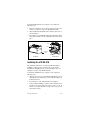
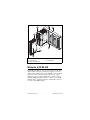
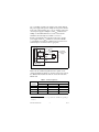
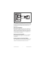
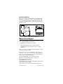
FieldPoint™ Operating Instructions
FP-DO-410 and cFP-DO-410
Eight-Channel, 5–30 V Protected Digital Output Module
These operating instructions describe how to install and use the
National Instruments FP-DO-410 and cFP-DO-410 digital output
modules (referred to inclusively as the [c]FP-DO-410). For
information about configuring and accessing the [c]FP-DO-410
over a network, refer to the user manual for the FieldPoint network
module you are using.
Features
The [c]FP-DO-410 is a FieldPoint digital output module with the
following features:
•
Eight digital output channels
•
Sourcing outputs supply up to 1 A per channel
•
Compatible with voltages from 5 to 30 VDC
•
On/Off LED indicators
•
Short-circuit protection with LED indicators
•
2,300 Vrms transient overvoltage protection
•
Hot swappable
•
–40 to 70 °C operation
Installing the FP-DO-410
The FP-DO-410 mounts on a FieldPoint terminal base (FP-TB-x),
which provides operating power to the module. Installing the
FP-DO-410 onto a powered terminal base does not disrupt the
operation of the FieldPoint bank.
To install the FP-DO-410, refer to Figure 1 and complete the
following steps:
1. Slide the terminal base key to either position X, used for any
module, or position 4, used for the FP-DO-410 module.
2. Align the FP-DO-410 alignment slots with the guide rails on
the terminal base.
3. Press firmly to seat the FP-DO-410 on the terminal base. When
the module is firmly seated, the terminal base latch locks it into
place.
Key
Latch
Alignment
Slot
Guide Rails
I/O Module
Terminal Base
Figure 1. Installing the FP-DO-410
Installing the cFP-DO-410
The cFP-DO-410 mounts on a Compact FieldPoint backplane
(cFP-BP-x), which provides operating power to the module.
Installing the cFP-DO-410 onto a powered backplane does not
disrupt the operation of the FieldPoint bank.
To install the cFP-DO-410, refer to Figure 2 and complete the
following steps:
1. Align the captive screws on the cFP-DO-410 with the holes on
the backplane. The alignment keys on the cFP-DO-410 prevent
backward insertion.
2. Press firmly to seat the cFP-DO-410 on the backplane.
3. Using a number 2 Phillips screwdriver with a shank of at least
64 mm (2.5 in.) length, tighten the captive screws to 1.1 N ⋅ m
(10 lb ⋅ in.) of torque. The nylon coating on the screws prevents
them from loosening.
FP-DO-410 and cFP-DO-410
2
ni.com
4
3
5
2
4
2
1
1 cFP I/O Module
2 Captive Screws
3 cFP Controller Module
4 Screw Holes
5 cFP Backplane
Figure 2. Installing the cFP-DO-410
Wiring the [c]FP-DO-410
The FP-TB-x terminal base has connections for each of the eight
output channels and for an external power supply to power the
output channels and field devices. The cFP-CB-x connector block
provides the same connections. Each channel has one output
terminal (VOUT), one supply terminal (VSUP), and two common
terminals (COM). All eight channels are referenced to the COM
terminals. The V and VSUP terminals are all internally connected,
as are the C and COM terminals.
© National Instruments Corp.
3
FP-DO-410 and cFP-DO-410
Use a 5–30 VDC external power supply for the output channels.
The power supply must provide enough current to power all of the
loads on the output channels, up to 1 A per channel.1 Connect the
external power supply to multiple V and VSUP terminals and to
multiple C and COM terminals as needed to ensure that the
maximum current through any terminal is 2 A or less.
Install a 2 A maximum, fast-acting fuse between the external
power supply and the VSUP terminal on each channel. Install a
1 A maximum, fast-acting fuse suitable for the load at the VOUT
terminal. Figure 3 shows fuses where appropriate.
V
C
VSUP 2 A max
VOUT 1 A max
Protected
Sourcing
Output
5–30 VDC
External Power
Supply
+
Load
–
COM
COM
To next channel
[c]FP-DO-410
Figure 3. Recommended Field Connections
Table 1 lists the terminal assignments for the signals of each
channel. Terminal assignments are also listed on the side panel of
the cFP-DO-410 and under the slide-in card on the front of the
FP-DO-410.
Table 1. Terminal Assignments
Terminal Numbers
1
1
Channel
VOUT
VSUP2
COM
0
1
17
2, 18
1
3
19
4, 20
2
5
21
6, 22
The maximum output current is 0.5 A per channel for a cFP-DO-410 operating at
55–70 °C.
FP-DO-410 and cFP-DO-410
4
ni.com
Table 1. Terminal Assignments (Continued)
Terminal Numbers
1
Channel
VOUT
VSUP2
3
7
23
8, 24
4
9
25
10, 26
5
11
27
12, 28
6
13
29
14, 30
7
15
31
16, 32
COM
1
Install a 1 A maximum, fast-acting fuse on each VOUT terminal.
2 Install a 2 A maximum, fast-acting fuse on each V and V
SUP terminal.
Digital Output Circuit
The [c]FP-DO-410 digital output channels are optically isolated
from the rest of the FieldPoint bank. The channels are sourcing
outputs with short-circuit protection circuitry. Sourcing current
means that the output terminal provides a path to a voltage supply.
In the ON state, a transistor is turned on between the positive
external supply voltage (V and VSUP) and the output (VOUT).
In the OFF state, this transistor is turned off, allowing only a small
leakage current to flow.
Ensure that the load on any channel does not draw more than 1 A,
and the total current supplied by all channels at any one time is no
more than 8 A.
For a cFP-DO-410 operating in the 55–70 °C
temperature range, the output current must not exceed
0.5 A on any channel.
Caution
In the ON state, the effective resistance between the output (VOUT)
and the supply voltage (V and VSUP) is 0.3 Ω. This resistance
causes a voltage drop between the external supply voltage and the
output voltage. Table 2 lists the actual output voltages based on the
voltage provided by the external power supply.
© National Instruments Corp.
5
FP-DO-410 and cFP-DO-410
Table 2. [c]FP-DO-410 Output Voltages for a 0.5 A Current Flow
V
VOUT
5
4.85
10
9.85
12
11.85
24
23.85
30
29.85
If the external power supply you are using does not provide one of
the voltages in Table 2, use the following equation to calculate the
actual voltage output.
ActualOutput = Vext – (Iflow × 0.3 Ω)
where
ActualOutput is the voltage sourced by VOUT
Vext is the voltage provided by the external power supply
Iflow is the current flow through the VOUT terminal
Protection for Inductive Loads
When an inductive load, such as a motor or relay, is connected
to an output, a large counter-electromotive force may occur at
switching time because of the energy stored in the inductive load.
This flyback voltage can damage the outputs and the power supply.
It is best to limit flyback voltages by installing a flyback diode
across an inductive load. Typically you should mount the flyback
diode within 18 in. of the load. Figure 4 shows one channel
connected to an inductive load with a flyback diode.
FP-DO-410 and cFP-DO-410
6
ni.com
V
C
VSUP
Protected
Sourcing
Output
1 A max
VOUT
Load
COM
Flyback Diode
for Inductive Loads
COM
To next channel
[c]FP-DO-410
Figure 4. Inductive Load with Flyback Diode
The [c]FP-DO-410 contains flyback diodes to prevent excessively
high voltage from damaging the module. National Instruments still
recommends using an external protection circuit across any
inductive load.
Short-Circuit Protection
If the protection circuitry detects a short-circuit condition on an
output channel, it disables the output. If the protection circuitry
disables an output that would otherwise be in the ON state, the
status indicator for that channel is still lit, but the output transistor
is turned off. Short-circuit protection is not a substitute for the
1 A fuse required on each channel.
Detecting a Short-Circuit Condition
When a channel is short-circuited, the red short-circuit LED for
that channel lights. Refer to Figure 5 for the locations of the
channel LEDs.
Resetting a Channel in a Short-Circuit Condition
To reset a channel in a short-circuit condition, determine the cause
of the condition and disconnect the load from the channel. The
channel resets automatically when the load is removed.
© National Instruments Corp.
7
FP-DO-410 and cFP-DO-410
Alternatively, if completely removing the channel load is not
convenient, reset the channel in any of the following ways:
•
In FieldPoint software, write a 0 to the channel. The channel
resets immediately.
•
Disconnect the external power supply from the [c]FP-DO-410.
•
Remove the [c]FP-DO-410 from the bank.
•
Power off the network module connected to the [c]FP-DO-410.
Normal operation can resume after you correct the short-circuit
condition.
Status Indicators
READY
POWER
Figure 5 shows the status indicator LEDs on the [c]FP-DO-410.
0
1
2
3
4
5
6
7
Figure 5. Status Indicators
The [c]FP-DO-410 has two green status LEDs, POWER and
READY. After you install the [c]FP-DO-410 onto a terminal base
or backplane and apply power to the connected network module,
the green POWER indicator lights and the [c]FP-DO-410 informs
the network module of its presence. When the network module
recognizes the [c]FP-DO-410, it sends initial configuration
information to the [c]FP-DO-410. After the [c]FP-DO-410
receives this initial information, the green READY indicator
lights and the module is in normal operating mode.
In addition to the green POWER and READY indicators, each
channel has two status LEDs. The green LED lights when the
channel is in the ON state. The red LED lights when the channel
is short-circuited. For more information about short-circuit
protection, refer to the Short-Circuit Protection section.
Upgrading the FieldPoint Firmware
You may need to upgrade the FieldPoint firmware when you add
new I/O modules to the FieldPoint system. For information on
determining which firmware you need and how to upgrade your
firmware, go to ni.com/info and enter fpmatrix.
FP-DO-410 and cFP-DO-410
8
ni.com
Isolation and Safety Guidelines
Read the following information before
attempting to connect the [c]FP-DO-410 to any circuits
that may contain hazardous voltages.
Caution
This section describes the isolation of the [c]FP-DO-410 and its
compliance with international safety standards. The field wiring
connections are isolated from the backplane and the inter-module
communication bus. The isolation is provided by the module,
which has optical and galvanic isolation barriers designed and
tested to protect against transient fault voltages of up to 2,300 Vrms.
Follow these guidelines to ensure a safe total system:
•
The [c]FP-DO-410 has a safety isolation barrier between the
I/O channels and the inter-module communication bus. There
is no isolation between channels unless otherwise noted. If any
of the channels on a module are wired at a hazardous potential,
make sure that all other devices or circuits connected to that
module are properly insulated from human contact.
•
Do not share the external supply voltages (the V and
C terminals) with other devices (including other FieldPoint
devices), unless those devices are isolated from human contact.
•
For Compact FieldPoint, you must connect the protective earth
(PE) ground terminal on the cFP-BP-x backplane to the system
safety ground. The backplane PE ground terminal has the
following symbol stamped beside it: . Connect the
backplane PE ground terminal to the system safety ground
using 14 AWG (1.6 mm) wire with a ring lug. Use the 5/16 in.
panhead screw shipped with the backplane to secure the ring
lug to the backplane PE ground terminal.
•
As with any hazardous voltage wiring, make sure that all
wiring and connections meet applicable electrical codes and
commonsense practices. Mount terminal bases and backplanes
in an area, position, or cabinet that prevents accidental or
unauthorized access to wiring that carries hazardous voltages.
•
Operate the [c]FP-DO-410 only at or below Pollution
Degree 2. Pollution Degree 2 means that only nonconductive
pollution occurs in most cases. Occasionally, however,
a temporary conductivity caused by condensation must be
expected.
© National Instruments Corp.
9
FP-DO-410 and cFP-DO-410
•
Refer to the FieldPoint product label for regulatory
certification under hazardous location standards. If the
FieldPoint product is not certified for operation in hazardous
locations, do not operate it in an explosive atmosphere or
where there may be flammable gases or fumes.
Specifications
The following specifications are typical for a range of –40 to 70 °C
unless otherwise noted.
Output Characteristics
Number of channels.......................... 8
Output type ....................................... Sourcing
Voltage range .................................... 5–30 VDC
Output impedance............................. 0.3 Ω
(0.3 V drop at 1 A)
Maximum output current
Per channel ................................. 1 A (0.5 A for cFP-DO-410
operating at 55–70 °C)
Maximum leakage current
OFF state .................................... 50 µA
Short-circuit condition................ 1 mA
Physical Characteristics
Indicators .......................................... Green POWER and
READY indicators,
eight green output state
indicators, eight red
overcurrent state indicators
Weight
FP-DO-410 ................................. 140 g (4.8 oz)
cFP-DO-410 ............................... 110 g (3.7 oz)
Power Requirements
Power from network module ............ 450 mW; 620 mW if some
or all channels are in
short-circuit condition
FP-DO-410 and cFP-DO-410
10
ni.com
Isolation Voltage
Channel-to-channel isolation ............ No isolation between
channels
Transient overvoltage........................ 2,300 Vrms
Environmental
FieldPoint modules are intended for indoor use only. For outdoor
use, they must be mounted inside a sealed enclosure.
Operating temperature ...................... –40 to 70 °C
Storage temperature .......................... –55 to 85 °C
Humidity ........................................... 10 to 90% RH,
noncondensing
Maximum altitude............................. 2,000 m; at higher altitudes
the isolation voltage ratings
must be lowered.
Pollution Degree ............................... 2
Shock and Vibration
These specifications apply only to the cFP-DO-410.
NI recommends Compact FieldPoint if your application
is subject to shock and vibration.
Operating vibration, random
(IEC 60068-2-64).............................. 10–500 Hz, 5 grms
Operating vibration, sinusoidal
(IEC 60068-2-6)................................ 10–500 Hz, 5 g
Operating shock
(IEC 60068-2-27).............................. 50 g, 3 ms half sine,
18 shocks at 6 orientations;
30 g, 11 ms half sine,
18 shocks at 6 orientations
© National Instruments Corp.
11
FP-DO-410 and cFP-DO-410
Safety
This product is designed to meet the requirements of the following
standards of safety for electrical equipment for measurement,
control, and laboratory use:
•
IEC 61010-1, EN 61010-1
•
UL 3121-1, UL 61010C-1
•
CAN/CSA C22.2 No. 1010.1
For UL, hazardous location, and other safety certifications, refer to
the product label or to ni.com.
Electromagnetic Compatibility
CE, C-Tick, and FCC Part 15 (Class A) Compliant
Emissions.......................................... EN 55011 Class A at 10 m
FCC Part 15A above 1 GHz
Immunity........................................... EN 61326:1997 + A2:2001,
Table 1
Note For EMC compliance, you must operate this device
with shielded cabling.
CE Compliance
This product meets the essential requirements of applicable
European Directives, as amended for CE marking, as follows:
Low-Voltage Directive (safety)......... 73/23/EEC
Electromagnetic Compatibility
Directive (EMC) ............................... 89/336/EEC
Note Refer to the Declaration of Conformity (DoC) for
this product for any additional regulatory compliance
information. To obtain the DoC for this product, click
Declarations of Conformity Information at
ni.com/hardref.nsf/.
FP-DO-410 and cFP-DO-410
12
ni.com
Mechanical Dimensions
Figure 6 shows the mechanical dimensions of the FP-DO-410
installed on a terminal base. If you are using the cFP-DO-410,
refer to the Compact FieldPoint controller user manual for the
dimensions and cabling clearance requirements of the Compact
FieldPoint system.
107.19 mm
(4.22 in.)
109.5 mm
(4.31 in.)
91.44 mm
(3.60 in.)
Figure 6. FP-DO-410 Mechanical Dimensions
Where to Go for Support
For more information about setting up the FieldPoint system, refer
to these National Instruments documents:
•
FieldPoint network module user manual
•
Other FieldPoint I/O module operating instructions
•
FieldPoint terminal base and connector block operating
instructions
Go to ni.com/support for the most current manuals, examples,
and troubleshooting information.
For telephone support in the United States, create your service
request at ni.com/support and follow the calling instructions
or dial 512 795 8248. For telephone support outside the United
States, contact your local branch office:
Australia 1800 300 800, Austria 43 0 662 45 79 90 0,
Belgium 32 0 2 757 00 20, Brazil 55 11 3262 3599,
Canada (Calgary) 403 274 9391,
Canada (Montreal) 514 288 5722,
Canada (Ottawa) 613 233 5949, Canada (Québec) 514 694 8521,
Canada (Toronto) 905 785 0085,
Canada (Vancouver) 514 685 7530, China 86 21 6555 7838,
© National Instruments Corp.
13
FP-DO-410 and cFP-DO-410
Czech Republic 420 2 2423 5774, Denmark 45 45 76 26 00,
Finland 385 0 9 725 725 11, France 33 0 1 48 14 24 24,
Germany 49 0 89 741 31 30, Greece 30 2 10 42 96 427,
India 91 80 51190000, Israel 972 0 3 6393737,
Italy 39 02 413091, Japan 81 3 5472 2970,
Korea 82 02 3451 3400, Malaysia 603 9131 0918,
Mexico 001 800 010 0793, Netherlands 31 0 348 433 466,
New Zealand 1800 300 800, Norway 47 0 66 90 76 60,
Poland 48 0 22 3390 150, Portugal 351 210 311 210,
Russia 7 095 238 7139, Singapore 65 6226 5886,
Slovenia 386 3 425 4200, South Africa 27 0 11 805 8197,
Spain 34 91 640 0085, Sweden 46 0 8 587 895 00,
Switzerland 41 56 200 51 51, Taiwan 886 2 2528 7227,
Thailand 662 992 7519, United Kingdom 44 0 1635 523545
FP-DO-410 and cFP-DO-410
14
ni.com
FieldPoint™, National Instruments™, NI™, and ni.com™ are trademarks of National Instruments Corporation.
Product and company names mentioned herein are trademarks or trade names of their respective companies.
For patents covering National Instruments products, refer to the appropriate location: Help»Patents in your software,
the patents.txt file on your CD, or ni.com/patents.
© 2002–2003 National Instruments Corp. All rights reserved.
*323355B-01*
323355B-01
Jul03

![[c]FP-DO-401 Operating Instructions](http://vs1.manualzilla.com/store/data/005693758_1-4b10a2df6965457ee651014d1377996a-150x150.png)