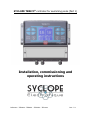
1
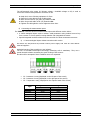
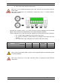
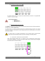
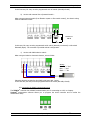
SYCLOPE TERE’O® controller for swimming pools (Part 1) Installation, commissioning and operating instructions Reference : TER0000 - TER0010 – TER0020 – TER xxxx Rev : 5.1 General informations Page 2/40 Parts of the general documentation ► Part 1 : Manual of installation, commissioning and operating instructions Part 2 : Manual of communication instructions General informations : SYCLOPE Electronique 2013® Notice of 11/08/2015 Analysers/controller for private and public swimming pools. Gamme TERE’O® Installation, commissioning and operating instructions Editor : SYCLOPE Electronique S.A.S. Z.I. Aéropole pyrénées Rue du Bruscos 64 230 SAUVAGNON - France – Tel : (33) 05 59 33 70 36 Fax : (33) 05 59 33 70 37 Email : [email protected] Internet : http://www.syclope.fr © 2012-2015 by SYCLOPE Electronique S.A.S. Subject to modifications Rev 5.1 Content Page 3/40 Content I. Généralités ................................................................................................................................ 4 1) Field application .................................................................................................................... 4 2) FCC conformity ..................................................................................................................... 5 3) Utilisation du document ......................................................................................................... 6 4) Signs and safety symbols ....................................................................................................... 6 5) Storage and transport ............................................................................................................ 7 6) Packaging ............................................................................................................................. 7 7) Warranty .............................................................................................................................. 7 II. Environment and safety procedures ........................................................................................ 8 1) Use of the equipment ............................................................................................................ 8 2) User obligations .................................................................................................................... 8 3) Risk prevention ..................................................................................................................... 8 4) Identification and localization of the identification plate ........................................................... 9 5) Disposal and conformity....................................................................................................... 10 III. Technical characteristics and functions ................................................................................. 11 1) Technical characteristics ...................................................................................................... 11 2) Main functions..................................................................................................................... 12 3) Parameter and scale of measurements ................................................................................. 12 IV. Installation and wiring ......................................................................................................... 13 1) Installation conditions .......................................................................................................... 13 2) Installation of the wall-mounted controllers........................................................................... 13 3) Opening/Closing the transparent door ................................................................................. 14 4) Opening/Closing connection cover ........................................................................................ 14 5) Electrical connections .......................................................................................................... 15 6) Changing internal fuses of P1 and P2 outputs ....................................................................... 15 7) Connecting primary power supply ......................................................................................... 16 8) Connecting the self-powered relay P1 ................................................................................... 17 9) Connecting the measurement inputs ..................................................................................... 18 10) Connecting the voltage reference REF .............................................................................. 20 11) Wiring the external control entry (E4) ............................................................................... 20 12) Connecting the RS485 communication port ....................................................................... 21 V. General use ........................................................................................................................ 23 1) Measurements come from gravity return line ........................................................................ 23 2) Measurements come from recirculating line .......................................................................... 23 VI. Commissioning .................................................................................................................... 25 VII. Programming the controller .................................................................................................. 25 1) Keypad and LCD display ...................................................................................................... 25 2) « Factory » setting values .................................................................................................... 27 3) Principle of programing ........................................................................................................ 27 4) Polarisation of sensor .......................................................................................................... 34 5) Calibration of the sensors .................................................................................................... 34 VIII. Entretien / Maintenance ....................................................................................................... 36 Installation, commissioning and operating instructions SYCLOPE TERE’O® General I. Page 4/40 General 1) Field application The analyser/controller of the SYCLOPE TERE’O® range you have just purchased is an electronic swimming-pool water management device. It has been carefully developed and manufactured to ensure your greatest pleasure and peace of mind. Its remarkable capacity for adapting to different conditions and sizes of private or public swimming pools means it can be installed in the most difficult of environments where control of water treatment and swimming-pool water regulation processes are decisive. The SYCLOPE TERE’O® range are equipped with one temperature entry and two specific electronic card adaptors for pH, ORP or chlorine/bromine for measurements using specific sensors for treating swimming-pool water and also include regulations processes with cyclic commands transmitted by means of two relays to control pH and chlorine levels. The simplicity of operation of the SYCLOPE TERE’O®, the user friendliness and the remarkable technical aspects of these devices, will ensure you benefit from their many options, guaranteeing you full control and supervision of the quality of the water in your swimming pool. The following instructions contain all the information required for the installation, use and maintenance of your new equipment. Packaging Installation Technical specifications Commissioning instructions Safety tips If you would like to receive further information or if you encounter any difficulties not described in this manual, please contact your usual retailer or else directly contact the sales department of SYCLOPE Electronique in France, either at the agency or at the office for your region or country, or the technical/quality departments of our establishments. We will do everything in our power to help you and ensure you benefit from our advice and know-how in the field of measurement and treatment of swimming-pool water. Contact : [email protected] Installation, commissioning and operating instructions SYCLOPE TERE’O® General Page 5/40 2) FCC conformity The SYCLOPE TERE’O® controller complies with Part 15 of the FCC Rules. Operation is subject to the following two conditions: (1) this device may not cause harmful interference (2) this device must accept any interference received, including interference that may cause undesired operation FCC Regulations state that unauthorized changes or modifications to this equipment may void the user’s authority to operate it. This equipment has been tested and found to comply with the limits for a Class B digital device, pursuant to Part 15 of the FCC Rules. These limits are designed to provide reasonable protection against harmful interference in a residential installation. This equipment generates, uses, and can radiate radio frequency energy and, if not installed and used in accordance with the instructions, may cause harmful interference to radio communications. However there is no guarantee that interference will not occur in a particular installation. If this equipment does cause harmful interference to radio or television reception, which can be determined by turning the equipment off and on, the user is encouraged to try and correct the interference by one or more of the following measures: Reorient or relocate the receiving antenna. Increase the separation between the equipment and receiver. Connect this equipment into an outlet on a circuit different from that to which the receiver is connected. Consult the dealer or an experienced radio/TV technician for help. Changes and modifications not expressly approved by the manufacturer could void the user’s authority to operate this equipment. Remark : To ensure compliance with the FCC regulations on electromagnetic interference for a class B device, use cables properly shielded and connected to the ground as recommended in this manual. The use of a cable that is not properly shielded or earthed for risk of violating the FCC rules. Installation, commissioning and operating instructions SYCLOPE TERE’O® General Page 6/40 3) Utilisation du document Please read this entire document before starting to install, adjust or commission your device, in order to ensure the safety of swimmers, users and equipment. The information provided in this document must be strictly observed. SYCLOPE Electronique S.A.S. declines all responsibility in cases where failure to comply with the instructions of this documents is observed. The following symbols and pictograms will be used to facilitate reading and understanding of these instructions. ● Information ► Action to be taken Item of a list or catalogue 4) Signs and safety symbols Identify a continuous voltage or a continuous current Identify an alternative voltage or an alternative current Protective ground Functional ground Risk of injury or accident. Identify a warning concerning a potentially dangerous risk. Documentation must be consulted by the user with each time the symbol is notified. If the instructions are not respected, that presents a risk of death, physical injuries or property damages. Electric hazard. Identify a warning statement relative to a mortal electric danger. If the instructions are not strictly respected, that implies an inevitable risk of physical injuries or death. Risk of incorrect operation or damage for the device. Comment or particular information. Recyclable element Installation, commissioning and operating instructions SYCLOPE TERE’O® General Page 7/40 5) Storage and transport It is important to store and transport your SYCLOPE TERE’O® in its original packaging in order to minimize risk of damage. Furthermore, the package must be stored in an environment that is protected against humidity and exposure to chemical products. Environmental conditions for transport and storage: Temperature : -10 °C to 70 °C Air humidity: Maximum of 90% with no condensation 6) Packaging The controller is delivered without electrical power cable. The pre-holes of the box are drilled and equipped with according electrical glands in compliance with IP65 level protection. Cables must be adapted to the electrical glands to respect the level of protection. Grounded cables for connecting pH and ORP (Redox) sensors are not provided. Content of the packaging : One analyzer/controller SYCLOPE TERE’O® Installation and starting instruction notice Programming notice Communication notice (Option) 7) Warranty The warranty is provided according to the terms of our general conditions of sale and delivery as long as the following conditions are met: Use of the equipment according to the instructions of this notice No modifications of the equipment which may modify its behavior and no incorrect manipulation Respect for the electrical safety conditions Consumable material is no longer covered by the warranty when in use. Installation, commissioning and operating instructions SYCLOPE TERE’O® Environment and safety instructions Page 8/40 II. Environment and safety instructions Please : Read this manual carefully before unpacking, installing or commissioning this equipment Take into account all the hazards and recommended precautionary measures Failure to respect these procedures can result in serious injury to users or damage the device. 1) Use of the equipment The SYCLOPE TERE’O® system has been designed to measure and regulate pH, Redox (ORP), chlorine (or bromine) by means of sensors and controls of suitable actuators in the context of the possible uses described in this manual. All other uses are considered to be non-conforming and must therefore be forbidden. SYCLOPE Electronique S.A.S. will not be responsible in any case for any damages that result from such uses. Any use of sensors or interfaces not-in conformity to the features defined in this handbook must also be proscribed. 2) User obligations The user undertakes not to allow its employees to work with the SYCLOPE TERE’O® equipment described in this manual unless they: Are aware of the fundamental instructions relating to work safety and prevention of accidents Are trained in the use of the device and its environment Have read and understood these instructions, warnings and manipulation rules 3) Risk prevention The installation and connection of the SYCLOPE TERE’O® equipment should only be performed by personnel specialized and qualified for this task. The installation must comply with current safety standards and instructions! Before switching the controller on or manipulating the relay outputs, remember always to cut off the primary power supply! Never open the controller when it is powered on! Maintenance operations and repairs should only be performed by trained, specialized personnel! Take care when choosing the location for installing the equipment according to the environment! The SYCLOPE TERE’O® electronic box should not be installed in a hazardous environment and should be protected against splashing with water or chemical products. It should be installed in a dry, well-ventilated location, isolated from corrosive vapours. Installation, commissioning and operating instructions SYCLOPE TERE’O® Environment and safety instructions Page 9/40 Make sure that the chemical sensors used with this device correspond well to the chemicals used. Refer to the individual technical note of each sensor. Chemistry of water is very complex, in case of doubt, contact immediately our engineering service or your approved installer/reseller. Chemical sensors are sensitive elements using consumable parts. They must be supervised, maintained and calibrated regularly using specific calibrator systems not-provided with this equipment. In the event of defect, a surplus possible hazard of chemical injections can be noted. In the doubt, a service contract must be taken near your reseller/installer or failing this near our engineering services. Contact your approved installer/reseller or our business service for more information. 4) Identification and localization of the identification plate 8 9 2 1 TERE’O 3 Ref: 4 S/N: IP65 6 14 151909989 TER 0000 90 - 240VAC 50/60Hz 10,2 - 0,16A 5 12 www.syclope.fr Made in France 7 13 15 This device compiles with the Part.15 of the FCC rules. Operation is subject to the following two conditions: (1) This device may not cause harmful interference, and (2) this device must accept any interference received, including interference that may cause undesired operation 10 11 1 Label of the manufacturer 9 Particular risks. Read the notice 2 Model of the product 10 Product which can be recycled 3 Reference of the product 11 Limitation of dangerous substances 4 Range of power supply 12 EC compliance 5 Values of the maximum current 13 Country of the manufacturer 6 Class of protection 14 Manufacturer square code 7 Identification of the manufacturer 15 Conformity with the FCC part 15 Class B 8 Serial number Identification plate Installation, commissioning and operating instructions SYCLOPE TERE’O® Environment and safety instructions Page 10/40 5) Disposal and conformity The recyclable packaging of the SYCLOPE TERE’O® current regulations. equipment must be disposed of according to Elements such as paper, cardboard, plastic or any other recyclable elements must be taken to a suitable sorting center. According to European directive 2002/96/EC, this symbol means that as of 12 August 2005 electrical appliances cannot be thrown out together with household or industrial waste. According to current regulations, consumers within the European Union are required, as of this date, to return their used devices to the manufacturer, who will take care of disposing them at no extra expense. According to European directive 2002/95/EC, this symbol means that the SYCLOPE TERE’O® controller is designed in compliance with the restrictions on hazardous substances According to low-voltage directive (2006/95/EC) and the electromagnetic compatibility directive (2004/108/EC), this symbol means that the device has been designed in compliance with the previously cited directives. In accordance with part 15 of the FCC regulation (Federal communications commission), this symbol indicates that the device was tested and approved under the respect and the conditions of the limits for a Class B digital device. Installation, commissioning and operating instructions SYCLOPE TERE’O® Technical characteristics Page 11/40 III. Technical characteristics and functions 1) Technical characteristics Type Consumption Power supply required Electric protection Operating temperature (ºC) Storage temperature (ºC) Humidity Case material Case dimensions Weight of the case Protection rating Display Measurement inputs Powered relays REF RS485 Internal fuses General characteristics Specification(s) 0,3 to 0,16A maximum (without external loads) Between 90V and 240V 50/60Hz Electronic fuse 160mA. Auto-rearmed when power off -5 °C to 45 °C (23 °F to 113 °F) -10 °C to 70 °C (10 °F to 158 °F) Max. 90% without condensation ABS or Polycarbonate (US and Canada) Length : 213 mm (8.4 inches) Width : 185 mm (7.3 inches) Height : 118 mm (4.6 inches) 1,1 kg IP 65 Screen LCD 128x128 with back light (White/blue) Entries 4x 0/4…20mA auto-powered entries (12V) without isolation… within : 2x programmable modules internally soldered. 4…20mA isolated module powered by 24VDC max pH isolated module Range : -400mV to +400mV Redox isolated module. Range : 0 to 1000mV Powered outputs 2x Powered relay outputs - Max. 5A / 250VAC - Inrush current Max. 15A <1ms 12VDC power output for supplying converters or external flow switch sensors. Communication port 1 RS485 communication port with compatible ModBus© RTU protocol. Protection of powered outputs Glass fuse 5x20mm 5A 250V fast Glass fuse 5x20mm 5A 250V fast Marker(s) F4 E1 to E4 P1 and P2 REF FUSE1 FUSE2 Main functions Page 12/40 2) Main functions Main functions Specification(s) Function Mode of control Proportional Actuator type Direction Powered relays 90…240VAC 5A Up or Down Alarms Low and high alarms Closed-loop control Flow switch control. Configuration Maintenance Std configuration Maintenance program Marker(s) Control from 0 to 100% Cycle time : 240s PWM command Expressed in real measurement values. Threshold controls up and down. Closed-loop control of injections with an external contact (filtering, for example) or with control of water circulation. Automatic selection of parameters Internal test program procedures 3) Parameter and scale of measurements Parameters T°C pH Redox (ORP) Free chlorine Bromine Measures and controls Scale of measurement -5 to 45°C 0 to 14 pH 0 to 1000 mV 0 to 2 ppm 0 to 10 ppm 0 to 2 ppm 0 to 10 ppm Precision ± 0,5 % ± 0,5 % ± 0,5 % ± 0,5 % ± 0,5 % ± 0,5 % ± 0,5 % Installation, commissioning and operating instructions SYCLOPE TERE’O® Installation and wiring Page 13/40 IV. Installation and wiring 1) Installation conditions To guarantee user safety and ensure correct operation of your SYCLOPE TERE’O®, please observe the following installation instructions: Install the controller in a dry location The controller must be protected against rain, frost and direct sunlight The room temperature must range between 0°C and 50°C, with no condensation. Choose an installation location free from vibration, on a suitable support and with no deformation If these instructions are not observed: The controller is at risk of being damaged The measurements can be disrupted The warranty is not applicable! 2) Installation of the wall-mounted controllers Before performing the installation and electrical connections, remember to turn off the power! The rating of IP65 is only guaranteed when the closing cover and the glass of the electric box are closed and when the cable glands match the diameters of your cables and are correctly sealed ► Drilling three holes ( 5-mm) according to the following drilling plan: ► ► ► ► ► Insert the 5-mm plugs using a hammer Insert the upper screw (top screw) first without completely tightening it Insert the lower screws and tighten them Tighten the upper screw Use a spirit level to check for correct and accurate fixing to the wall. Installation and wiring 3) Page 14/40 Opening/Closing the transparent door To ensure IP65 protection class, the transparent door must be closed after usage and being sure of the O-ring quality each time. The controller box is equipped with an automatic lock system which must be understood to manipulate it. For opening the transparent door: Locked … Raise the lock and pull forward it. Opened! For opening and locking transparent door: Pass the fingers behind the lock and bring the door with the inch … With the palm of the hand, press on the transparent door and tighten with the hand to lock. Locked! 4) Opening/Closing connection cover To ensure IP65 protection class, the connection cover must be closed after usage and the Oring must be checked each time. Use a specific screwdriver to remove the two screws for opening the cover. Installation, commissioning and operating instructions SYCLOPE TERE’O® Installation and wiring Page 15/40 5) Electrical connections The electrical installation must be performed in accordance with current standards by authorized personnel! A 30mA differential circuit breaker must be installed! A breaker circuit of maximum 10A must be installed near the controller and easily accessible to stop the main power. It must be identified as a circuit-breaker for the controller! Before performing the connections, remember to turn off the power! Use multicore cables if possible! If not possible, always use a special wiring tip to be sure that wires do not make a contact together! Protect the wirings by using electrical clamps. The SYCLOPE TERE’O® controller must be connected to the main circulation pump system by means of “E4” entry and with the flow-switch of the measuring chamber. Internal protection : The controller is protected by an internal resettable fuse of 160mA and by a varistor of 275VAC for surge protection. The self-powered relays P1 and P2 are protected each by a glass 5x20 fuse of 5A 250V. Reference FUS5X20R5000 Name Fast glass fuse 5x20mm 5A 250V In case of fuse destroyed, check that the card is not burnt out. If this is the case, the complete card must be changed! In case of varistor burned, please return the controller to our technical after-sales department for repairing! 6) Changing internal fuses of P1 and P2 outputs Before changing any fuse, disconnect the power supply. Use only an original fuse. Don’t replace it by another one with a higher current ! Open the translucid door and remove the 4 screws with an adequate screwdriver. Disconnect de flat cable between the electronic cards carefully. Installation, commissioning and operating instructions SYCLOPE TERE’O® Installation and wiring Page 16/40 Localise the fuse to be changer on the bottom card … Remove the protection cover on the support of fuse … Change the fuse and reinstall the protection cover. Fuse 1 and fuse 2 Fast fuse 5A 5x20mm Glass Reconnect the flat cable between the electronic cards and put the 4 screws to fix the front face. Don’t screw them hardly because the electronic box is made in plastic material. 7) Connecting primary power supply The SYCLOPE TERE’O® controller is equipped with a switching power supply. It is therefore able to be supplied by AC voltage comprised between 90V to 240V - 50/60Hz. Installation, commissioning and operating instructions SYCLOPE TERE’O® Installation and wiring Page 17/40 ► Use a 3-point 1.5 mm2 cable to wire the power supply ► Strip the 3 wires for 7mm ► Pass the 3-point cable through a cable gland ► Wire the live cable to L1 and the neutral to N located “X1” ► Wire the ground to the ground plot with an insulated round terminal Câbler la terre sur le plot PL1 à l’aide d’une cosse à œillet M4 ► Tighten the cable gland to ensure tightness when done. The SYCLOPE TERE’O® controller does not have its own independent power switch. It is directly powered when connected to the main power supply. 8) Connecting the self-powered relay P1 ● Connecting the self-powered relay P1 The self-powered relay output P1 (Primary voltage = Available voltage on P1) is used to control the measurement parameter connected on E1. ► ► ► ► ► Strip the 2 wires of dosing equipment for 7mm Pass the 3-point cable through a cable gland Wire the two wires to (11) and (12) located on P1 Wire the ground cable on PE (13) located on P1 Tighten the cable gland to ensure tightness when done. ● Connecting the powered relay P2 Installation, commissioning and operating instructions SYCLOPE TERE’O® Installation and wiring Page 18/40 The self-powered relay output P2 (Primary voltage = Available voltage on P2) is used to control the measurement parameter connected on E2. ► ► ► ► ► Strip the 2 wires of dosing equipment for 7mm Pass the 3-point cable through a cable gland Wire the two wires to (14) and (15) located on P2 Wire the ground cable on PE (16) located on P2 Tighten the cable gland to ensure tightness when done. 9) Connecting the measurement inputs The TERE’O® controller has three measurement inputs with different version either: 4…20mA analogical inputs used to measure multi-parameters using isolated current loop from a sensor or from a specific housing chamber with integrated converters. Special integrated modules soldered into the controller for direct measurement sensors. a) 4…20mA analogical inputs without internal module version All entries are self-powered by internal 12VDC power supply and must be used without external supplies!! Analogical entries of the controller are not isolated! The use of SYCLOPE Electronique technology measuring cells is mandatory. They use a special internal isolation warranting the good working of the sensors! No claim will be accepted if these conditions were not respected! E1 : Parameter 1 entry (Displayed on the left part of the screen) E2 : Parameter 2 entry (Displayed on the right part of the screen) E3 : Temperature entry (Displayed on the superior band of the screen) Type pH Chlorine Bromine Redox Temperature Flow switch Wiring of SYCLOPE measuring chamber + Green Blue White Black White Black Yellow Orange White / Blue White / Yellow Violet Grey Installation, commissioning and operating instructions SYCLOPE TERE’O® Installation and wiring Page 19/40 b) Direct entries with internal modules version Only “E3” is a not isolated self-powered (12V) entry and must be used without external power supply! This entry is dedicated to the temperature measurement using a 4…20mA SYCLOPE Electronique sensor. According the controller version, 1 or 2 BNC connectors could be implanted near the electrical glands. These connectors are wired directly to the internal entries E1 or/and E2. In this configuration, E1, E2 and E3 entries are affected by the factory and must not be changed. Version T°C, pH, Chlorine T°C, pH, Bromine T°C, pH, Redox E1 : pH entry (BNC) (Displayed on the left part of the screen) E2 : Chlorine or Bromine or Redox (BNC) entry (Displayed on the right part of the screen) E3 : Temperature entry (Displayed on the superior band of the screen) Parameter T°C pH Terminal E3 Terminal E3 Terminal E3 BNC E1 BNC E1 BNC E1 Chlorine or Bromine Terminal E2 Terminal E2 - Redox BNC E2 Wiring of the pH and Redox (ORP) entries must be respected! Risks of uncontrolled injection of chemical products! Don’t touch internal pin of the BNC connectors! Risks of destroying internal electronic components. Installation, commissioning and operating instructions SYCLOPE TERE’O® Installation and wiring Page 20/40 10) Connecting the voltage reference REF The voltage reference allow you to power the external electronic converters. It is programmable to deliver a 12V power supply. Do not invert polarity ! Red wire on “+” Brown wire on “ – ” 11) Wiring the external control entry (E4) The TERE’O® controller has a remote control input (E4) which stops the controls of dosing equipments. This input is a 4…20mA analogical input. An external resistor is normally connected on this entry for authorizing dosing processes if not external command is requested. If you decide to control dosing processes by an external signal, you must realize the function as follow. For safety reason, it is strongly recommended to use this function with an external switch which comes from the filtration system to prevent overdosing of chemical products! a) Version with 4…20mA sensor used by SYCLOPE : When using SYCLOPE measuring cells, it is optional to have an analogical flow switch detector under reference DEB0000. In this case, the external resistor must be removed and the analogical flow switch must be connected as follow: Violet Gris ∞ DEB0000 Installation, commissioning and operating instructions SYCLOPE TERE’O® Installation and wiring Page 21/40 In this first case, E4 entry must be programmed as a NC switch (Normally Closed) b) Version with external free of potential switch : When using an external switch (from filtration system or flow-switch control), the electric wiring must be realized as follow: Résistor of 680 Ω Switch In this case, E4 entry must be programmed as NC switch (Normally Connected) or NO switch 5Normally Open). The controller is provided with NC configuration. c) Version with PNP inductive switch : When using an inductive electronic detector, wire as follow: Wiring : Brown : “+” Ref Blue : “-” Ref Black : “-” E4 Inductive detector provided by SYCLOPE is PNP type with 3 wires. In this last case, E4 entry must be programmed as a NC switch (Normally Closed) 12) Connecting the RS485 communication port The TERE’O® controller has a RS485 communication port for connecting to a PLC or a laptop. TerCom® maintenance software allows you to program the entire controller and to realize the maintenance easily. Installation, commissioning and operating instructions SYCLOPE TERE’O® Installation and wiring Respect Page 22/40 polarities and connections of the bus. A terminal to signal AA’ (n°3) of USB/RS485 converter B terminal to signal BB’ (n°4) of USB/RS485 converter C terminal to GND (n°5) of USB/RS485 converter To connect TERE’O® controller to a PLC or a laptop, we recommend to use a specific USB/RS485 converter. Please refer to the “communication Manuel” for wiring and programming. Reference INF1021 Name Interface converter USB 485 Refer to the “Communication Manuel” for more informations about all possibilities of connection. Installation, commissioning and operating instructions SYCLOPE TERE’O® General use Page 23/40 V. General use SYCLOPE TERE’O® controller is intended to measurement and to control parameters for water treatment of swimming pools. This equipment can be use under two different fundamental principes described below: Measurement of parameters come from the gravitating return line Measurement of parameters come from the recirculating filtration circuit. 1) Measurements come from gravity return line This type of installation is recommended when more swimming pools are connected only to one buffer tank and one block of filters. Swimming pool pH Cl Dosing pumps Heater Buffer tank Filter Measuring cell on return pipe Circulation pump Water is sampled in the gravitating return line. The sensors, installed into the measuring cell, receive water to be analysed and send the values to the controller. According to the setting points fixed by the user, the controller sends proportional orders to the pumps installed into the main intake line of the swimming pool. Be careful to the distance between the injection points of chemistry products into the swimming pool and the return line. The water must be homogeneous before coming in the return line. 2) Measurements come from recirculating line This type of installation is recommended in the event of single swimming pool where filtration circuit is independent. Utilisations générales Page 24/40 Water is sampled after the recirculating pumps and before the filter entry. (If using, before flocculent injection circuit) The sensors installed into the measuring chamber receive water to be analysed and send the values to the controller. According to the setting points fixed by the user, the controller sends proportional orders to the pumps installed into the main intake line of the swimming pool. Swimming pool pH Cl TERE’O controller Dosing pumps Waste Heater Sampling circuit Measuring cell Buffer tank Filter Circulation pump Swimming pool pH Cl TERE’O controller Dosing pumps Sampling circuit Waste Heater Measuring cell Buffer tank Filter Circulation pump Installation, commissioning and operating instructions SYCLOPE TERE’O® Commissioning Page 25/40 VI. Commissioning You have just carried out electrical connections, you have installed sensors and you have connected dosing equipments, you are thus ready to carry out the startup of your SYCLOPE TERE’O® controller. Apply the power supply on the controller Check if no visual problem appear, if the controller is well lit and if the other equipments of the installation are not disturbed. SYCLOPE TERE'O® controller does not launch automatically the chemistry treatments. The user is the main master for launching the controller after checking the good programation according the needs. SYCLOPE TERE’O® is full programmable. During the power up, the preset parameters are fixed and all regulation processes are inactive. SYCLOPE TERE’O® controller is delivered with standard programming. It is advisable for the user to modify this programming if it does not correspond to the needs. To modify the programming of the controller, please refer to the following chapter. VII. Programming the controller The TERE'O® controllers are equipped with a keyboard and a LCD display to establish the dialog between the user and the machine. Ensure the good programming of the TERE’O® controller before starting regulations! An excess of chemical products can cause harmful actions on the human health and the environment. 1) Keypad and LCD display The LCD display is a 128x128 dots matrix with blue back-light and white writing. By internal software, the screen is separated as follow: The higher part indicates the temperature measurement (entry E3), the state of switch control (E4) and the states of P1 and P2 relays. The left part indicates the measurement values, controls and alarms of the parameter connected on E1 entry. The right part indicates the measurement values, controls and alarms of the parameter connected on E2 entry. The keypad is symmetrical. The left part of the keyboard gives access to the adjustments of the parameter selected on the left part of the LCD display. The right part of the keyboard gives access to the adjustments of the parameter selected on the right part of the LCD display. HMI interface Page 26/40 OK key: a short push allows the validation of the operation. ESC key: a short push allows erase or return to the preceding operation. A long push gives you access to the general menu of the controller. Key: a short push makes it possible to move into the menus or to increment a value. A long push allows a fast increment of a value. Key: a short push makes it possible to move into the menus or to decrement a value. A long push allows a fast decrement of a value. Calibration Key: a short push allows the calibration of the corresponding sensor. A long push allows the inhibition of the polarization time for the corresponding sensor. Mode Key: a short push makes it possible to select the operating process of the controller (Manual or AUTO) when the regulation is launched (START Key). A long push gives access the adjustments of the sensor parameters. Start/Stop Key: allows to activate/deactivate the processes. The sensor connected to E1 entry is displayed on the left part of the screen. The sensor connected to E2 entry is displayed on the right part of the screen. Programming the controller Page 27/40 2) « Factory » setting values Whatever the type of operation chosen, the following configurations are carried out by the factory: Language: French Contrast: 50 % Parameter 1: Chlorine range :10ppm - Set point: 2ppm High threshold: 5ppm – Low threshold: 1,5ppm Parameter 2: pH – Set point: 7,2pH High threshold: 8,5pH – Low threshold: 6,5pH Flow control entry : NC (Normally closed) Controls : Inactives Proportional band Bp : 10% Cycle time of PWM: 120 s. 3) Principle of programing The display of the SYCLOPE TERE’O® controller is separated in 3 parts: A main programming screen A label for each parameter adjustment A screen of measurement values and dosing in progress. a) Main programming menu A long push on one of the two ESC keys gives access to the main programming menu… once in the this menu, a short push on ESC key makes it possible to get out immediately. Configuration ● Language ●Contrast ●Flow switch (E4) ●Calibration Temp. ●Temperature display ●Factory settings ●Communication The keys and allow to navigate in the menu. The key allows you to confirm your choice The key allows you to leave the configuration menu V :x.xx – Sn : xxxxxxxxx Language Configuration ● Language French ●Contrast ●Flow switch (E4) ●Calibration Temp. ●Temperature display ●Factory settings ●Communication V :x.xx – Sn : xxxxxxxxx By pushing on OK key whereas the line “Language” is in intensified brightness allows to have access to language selection. The and keys allow to show the available languages. The validation is done by pushing OK key. In any case, it is possible to return to the previous state without validation by a short pushing the ESC key. Configuration ●Language ● Contrast 50% ●Flow switch (E4) ●Calibration Temp. ●Temperature display ●Factory settings ●Communication V :x.xx – Sn : xxxxxxxxx Contrast By pushing on OK key whereas the line “Contrast” is in intensified brightness allows to have access to adjust contrast value. The and keys allow to increase/decrease the contrast value in realtime. Once desired contrast is reached, the validation is done by pushing OK key. In any case, it is possible to return to the previous state without validation by a short pushing the ESC key. Installation, commissioning and operating instructions SYCLOPE TERE’O® Programming the controller Page 28/40 Configuration ●Langue ●Contrast ● Flow switch (E4) NO ●Calibration Temp. ●Temperature display ●Factory settings ●Communication V :x.xx – Sn : xxxxxxxxx Flow switch (E4) By pushing on OK key whereas the line “Flow switch” is in intensified brightness allows to have access to select the polarity of the circulation flow switch. The and keys allow to select the state of the recirculation flow switch “NO” (normally open) or “NC” (normally closed). Once the good value is selected, the validation is done by pushing OK key. In any case, it is possible to return to the previous state without validation by a short pushing the ESC key. Calibration temperature Calibrations are determining operations for good working of the controller and best treatment of the swimming pool! A bad calibration could be dangerous for your health and your swimming pool. It can cause corrosions and destruction of the swimming pool parts. In any doubt about the procedure, contact our after sale service! A bad setting point could cause excessive consumptions of calories and harm the environment! Configuration ●Language ●Contrast ●Flow switch (E4) ● Calibration Temp. 22°C ●Temperature display ●Factory settings ●Communication Configuration ●Language ●Contrast ●Flow switch (E4) ● Calibration Temp. 22°C Calibration OK Temperature display ●Factory settings ●Communication Configuration ●Language ●Contrast ●Flow switch (E4) ● Calibration Temp. 22°C Calibration LIMIT ●Temperature display ●Factory settings ●Communication By pressing on OK key whereas the line “Calibration Temp.” is in intensified brightness allows to have access to the temperature sensor calibration. This calibration procedure use only one point. The and keys allow to adjust the measured value to the real value of the temperature. The validation is done by pushing OK key. If the calibration procedure is correctly proceeded, the “Calibration OK” message is displayed. ● Calibration If the system detects that the last calibration point is a little bit away from the theoric value, the temperature sensor calibration is done but a “Calibration LIMIT” message is displayed. That means that the temperature sensor is still in operating condition but must be replaced soonest. Installation, commissioning and operating instructions SYCLOPE TERE’O® Programming the controller Configuration ●Language ●Contrast ●Flow switch (E4) ● Calibration Temp. 22°C Calibration ERROR ●Temperature display ●Factory settings ●Communication Page 29/40 If the system detects that the last calibration point is too far away from the theoric value, the temperature sensor calibration is cancelled and “Calibration ERROR” message is displayed. That means the temperature sensor is working bad or is broken. Please, replace it immediately. Configuration ●Language ●Contrast ●Flow switch (E4) ●Calibration Temp. ● Temperature display ON ●Factory settings ●Communication V :x.xx – Sn : xxxxxxxxx By pressing on OK key whereas the line “Temperature display” is in intensified brightness allows to have access to the choice of activation or deactivation of the temperature displaying in the main screen. The and keys allow to select ON or OFF state. The validation is done by pushing OK key. Configuration ●Language ●Contrast ●Flow switch (E4) ●Calibration Temp. ●Temperature display ● Factory settings OK/Esc ●Communication V :x.xx – Sn : xxxxxxxxx Displaying temperature or not Factory settings By pressing on OK key whereas the line “Factory settings” is in intensified brightness allows to reload the memory by default settings like statement in the paragraph: The sensor connected to E1 entry is displayed on the left part of the screen. The sensor connected to E2 entry is displayed on the right part of the screen. To validate press OK key! To cancel press ESC key Be careful! This operation is irreversible. Once validated by OK key, all your personal configuration parameters will be lost. Configuration ●Language ●Contrast ●Flow switch (E4) ●Calibration Temp. ●Temperature display ●Factory settings ● Communication Communication By pressing on OK key whereas the line “Communication” is in intensified brightness allows to have access to communication RS485 ModBus configuration. This window also allows to verify the connection statute of the socket modem when activated. V :x.xx – Sn : xxxxxxxxx ● Speed : 9600 ●Parity : Even ●Adress : 1 ●Protocol : RTU ●Modem : No Modem By using and keys allow to select the parameter to be modified, when the desired parameter is in intensified brightness. Press on OK key to enter in modification mode. In modification mode (line blinking) the and keys allow to modify the value. To validate, press OK key! To cancel and to return to the previous menu, press ESC key! Installation, commissioning and operating instructions SYCLOPE TERE’O® Programming the controller Page 30/40 For more information, refer to the communication manual of the controller. (Manual 2) b) Setting parameter values ● Sensor ●Alarms ●Control ●Direction ●Period time ●Calibration By pressing long time on Mode key of the left part gives access the menu of the measured parameter from E1 entry. In this menu, navigation is performed by using , , OK and ESC keys on the left part of the display affected to parameter 1. As the left part, the right part uses the Mode key to access the menu of measured parameter from E2 entry. In this case, navigation is performed using , , OK and ESC key of the right part of the display affected to parameter 2. Choice of the sensor The modification of the sensor is only possible if you press START/STOP key when starting the controller. Once the sensor is chosen and the controls started, the choice of sensor is deactivated again. ● Sensor Cl 10ppm ●Alarms ●Control ●Direction ●Period time ●Calibration The access to the choice of sensor is performed by pressing OK when “Sensor” line is selected in intensified brightness. The , keys allow to select the registered sensors. Once the sensor chosen, use OK key to validate the choice. In any time, it is possible to leave this menu without validating the choice by pressing on ESC key. ●Sensor ● Alarms 5.00 1.50 ●Control ●Direction ●Period time ●Calibration The access to alarm thresholds sub-menu is performed by pressing OK when “Alarms” line is selected in intensified brightness. The following sub-menu appears: Previously, by pressing on and keys allow to set the highest alarm threshold corresponding to the parameter. Then done, press on OK key to validate the high value. Once the high threshold validated, use and keys to set the lowest alarm threshold and press OK to validate the low value. In any time, it is possible to leave this menu without validating the alarm thresholds by pressing on ESC key. ●Sensor ●Alarms ● Control Prop. 10% ●Direction ●Period time ●Calibration Alarm thresholds Choice of control mode The access to the choice of control mode sub-menu is performed by pressing OK when “Control” line is selected in intensified brightness. The following sub-menu appears: The and keys allow to select PROP mode for proportional control or HYST mode for a control by hysteresis. Once the control mode is chosen, use OK key to validate. In any time, it is possible to leave this menu without validating the alarm thresholds by pressing on ESC key. Installation, commissioning and operating instructions SYCLOPE TERE’O® Programming the controller Page 31/40 ●Sensor ●Alarms ● Control Prop. 10% ●Direction ●Period time ●Calibration Setting of proportional/hysteresis band The access to the proportional/hysteresis band setting sub-menu is performed by pressing OK when “Control” line is selected in intensified brightness. The following sub-menus appears: By pressing on and keys allow to set the proportional band corresponding to the parameter. In any time, it is possible to leave this menu without validating the proportional band by pressing on ESC key. Proportional band (Bp) is understood as “% of full scale (Fs)”. That means for a pH full scale of 0 to 14pH and a proportional band of 10%, the dosage value will be 100% when the gap with the setting point will be >= to: Fs*(Bp)*% = 14 x 10 x (1/100) either 1,4pH Hysteresis (Hy) is understood as « % of full scale (Fs) centred on the set point. That means for a full scale of 0 to 10ppm for chlorine parameter and a hysteresis value of 10%, the differential value will be: Fs*(Hy)*% = 10 x 10 x (1/100) either 1ppm. If the set point is 2ppm, the dosage will be activated between 1,5 and 2,5ppm. ●Sensor ●Alarms ●Control ● Direction Growing ●Period time ●Calibration The access to the direction of control is performed by pressing OK when “Direction” line is selected in intensified brightness. The following sub-menu appears: By pressing on and keys allow to select “Growing” or “Decreasing” direction corresponding to the control of parameter. In any time, it is possible to leave this menu without validating the proportional band by pressing on ESC key. ●Sensor ●Alarms ●Control ●Direction ● Period time 120s ●Calibration Period time setting The access to the period time of control is performed by pressing OK when “Period time” line is selected in intensified brightness. The following sub-menu appears: Setting of the period time is allowed by using and keys to adjust it between 10 to 240 s. When done, press OK to validate the value. In any time, it is possible to leave this menu without validating the cycle time by pressing on ESC key. ●Capteur ●Alarmes ●Régul. ●Dosage ●Durée cycle ●Calibration Offset 0.12 Mes : 0.15 Direction of control Calibration of the offset/pH7 of the sensor The access to the offset/ph7 calibration sub-menu is performed by pressing OK when the “Calibration” line is selected in intensified brightness and OK again when the “offset” lines appear with a value to be adjusted for calibrating zero of amperometric sensor and of pH=7 for pH sensor. Measurement value of the parameter appears on “Mes” line. By pressing on and keys allow to set the reference value. When the good value is entered, press OK key to validate. Installation, commissioning and operating instructions SYCLOPE TERE’O® Programming the controller Page 32/40 Calibration of the gain or pH4 of the sensor The access to the Gain/ph4 calibration sub-menu is performed by pressing OK when the “Calibration” line is selected in intensified brightness and OK again when the “Gain” lines appear with a value to be adjusted when away of 0 value for calibrating gain (or slope) of amperometric sensor and of pH=2 to 6 and pH=8 to 12 for pH sensor. Measurement value of the parameter appears on “Mes” line. By pressing on and keys allow to set the reference value. When the good value is entered, press OK key to validate. ●Sensor ●Alarms ●Control ●Direction ●Period time ● Calibration Gain 2.56 Mes : 2.60 - Resetting calibration The access to the resetting calibration sub-menu is performed by pressing OK when the “Calibration” line is selected in intensified brightness and OK again when the “RAZ” line appears. By pressing on OK key will reset all calibration of the corresponding parameter. In any time, it is possible to leave this menu without reset by pressing on ESC key. ●Capteur ●Alarmes ●Régul. ●Dosage ●Durée cycle ●Calibration RAZ OK/Esc Be careful! This operation is irreversible. Once validated by OK key, all your personal configuration parameters will be lost. c) Screens of measurements and dosing in progress This screen is the operational screen of your controller. It is composed of three parts: Left part corresponding to the measured parameter on E1 entry. Right part corresponding to the measured parameter on E2 entry. High band part giving various operating information. Displaying the measurement value The measured value is displayed according to the range of the selected sensor… This field can take four different statutes: Measured value. Value higher than the range of the sensor. Value lower than the range of the sensor. Unconnected sensor The symbol Displaying setting point represent the setting point value. Installation, commissioning and operating instructions SYCLOPE TERE’O® Programming the controller Page 33/40 This last one is programmable directly from the main screen by using and keys corresponding to the parameter. Validate by pressing OK key! If the modification is not validated before 5s, it will not be registered. Displaying dosing controls The dosing control symbol can take five different statutes. Automatic dosing control Dosing control in pause Dosing control stopped Dosing control deactivated (Main stop) Manual dosing control (Manual working) When started the controller, dosing control is stopped: By pressing on START key launches the regulation of the two parameters according their setting points. If the sensor polarization is not finished (the symbol mode (symbol ). is present), the regulation is in pause When polarization is finished (the symbol disappears), the automatic dosing controls are activated ( ). If you wish to select manual dosing control on one of the two parameters, press on the MODE key allows to pass in manual dosing control (symbol ), an additional pressing on MODE key allows to pass in desactived mode (symbol ), again, another additional pressing on MODE key allows to return in automatic mode. By pressing on STOP key allows to stop the regulation of the two parameters (symbol Pressing MODE key is without effect when the regulation is stopped. ). Displaying alarms Bottom of the display part informs about the thresholds and the states of alarms. High alarm value : Threshold 8.3pH High alarm activated Low alarm value : Threshold 6.5pH Low alarm activated Displaying statutes in the higher display band The higher display part gives informations about E3 and E4 entries and P1 and P2 relay outputs. The value displayed in the left higher corner indicates the temperature. The symbol informs that the water does not circulate into the measuring chamber. The symbol informs that the P1 output is activated. The symbol informs that the P2 output is deactivated. Installation, commissioning and operating instructions SYCLOPE TERE’O® Programming the controller Page 34/40 4) Polarisation of sensor When starting the controller or when connecting of a new sensor, the symbol will appear. This symbol indicates that the polarization of the sensor is in progress. During this programmed time fixed at 2 minutes, the regulation, if it is launched, is put in pause mode (symbol ). During this period, it is impossible to reach adjustments or calibrate the sensor. By pressing on CALIB key allows to inhibit the polarization time of the corresponding sensor. 5) Calibration of the sensors The CALIBRATION key allows to carry out a calibration of the sensor with who’s connected on E1 or E2 entries with only one reference value. Calibrations are determining operations for good working of the controller and best treatment of the swimming pool! A bad calibration could be dangerous for your health and your swimming pool. It can cause corrosions and destruction of the swimming pool parts. In any doubt about the procedure, contact our after sale service! A bad setting point could cause excessive consumptions of calories and harm the environment! Before carrying out the calibration, pH or Redox or Chlorine or Bromine measurements must be performed with special equipment using chemical reagents. This operation does not require the stop the recirculating pumps nor the removing sensors from the measuring cell. The chemical reagents for pH or Redox (ORP) or Chlorine or Bromine measurements are not provided with the controller. To proceed an automatic calibration: Recirculating circuit must work since several minutes Displayed value must be stable Dosing pumps must be stopped By pressing on the CALIBRATION key causes measured value zone in intensified brightness. Use and keys to adjust the value according your reference. When done, press OK to validate! During this operation, press on ESC key to cancel the calibration or wait 5 seconds without any action on any key. Controller will recover the previous display before calibration procedure. If the sensor calibration correctly proceeded the message “Calibration OK” is displayed. Installation, commissioning and operating instructions SYCLOPE TERE’O® Programming the controller Page 35/40 If the system detects that the last calibration point is a little bit away from the theoric value, the sensor calibration is done but a “Calibration LIMIT” message is displayed. That means that the sensor is still in operating condition but must be replaced soonest. If the system detects that the last calibration point is too far away from the theoric value, the sensor calibration is cancelled and “Calibration ERROR” message is displayed. That means the sensor is working bad or is broken. Please, replace it immediately. Installation, commissioning and operating instructions SYCLOPE TERE’O® Maintenance Page 36/40 VIII. Maintenance The controller is without maintenance. Repairs must be carried out only by qualified technicians and must be carried out in our factory of SAUVAGNON. For any problem concerning the controller or councils about water treatment, do not hesitate to contact our after sale service. Installation, commissioning and operating instructions SYCLOPE TERE’O® Certificat CE Page 37/40 Installation, commissioning and operating instructions SYCLOPE TERE’O® Certificat CE Page 38/40 NOTES Installation, commissioning and operating instructions SYCLOPE TERE’O® Certificat CE Page 39/40 Installation, commissioning and operating instructions SYCLOPE TERE’O® SYCLOPE Electronique S.A.S. Z.I. Aéropole Pyrénées 64 230 SAUVAGNON Tel : (33) 05 59 33 70 36 Fax : (33) 05 59 33 70 37 Email : [email protected] © 2012-2015 by SYCLOPE Electronique S.A.S. Subject to modifications.