1
Power quality analyser Alptec 2333b
2333b
Installation Note
Included: First steps with the WINALP2400 software
About this Document
Document Name :
InstallationNoteAT2333b_rev1.1E.doc
Version:
ENGLISH
The technical data contained in this document is subject to changes
without prior notice, due to continued product development and
improvements made by the manufacturer.
© ALPES TECHNOLOGIES S.A. All rights reserved.
2
ALPTEC2333b
About this Document
About this Document
Summary
1
About this Document ..................................................................................................... 6
1.1.
Document structure................................................................................ 6
1.2.
Signs and symbols................................................................................. 6
2
General Safety Instructions........................................................................................... 7
3
General dimension.......................................................................................................... 9
3.1.
Overall dimensions ................................................................................ 9
3.2.
Size of the voltage wires : .................................................................... 10
3.3.
size of the current wire : ....................................................................... 10
4
General safety instruction ........................................................................................... 11
5
Design and functions .................................................................................................... 12
5.1.
Terminals............................................................................................. 12
5.2.
Display and control information ............................................................ 13
5.3.
Switches .............................................................................................. 14
5.4.
Factory settings ................................................................................... 15
6
Start-up the device ....................................................................................................... 16
6.1.
Checking of delivery............................................................................. 16
6.2.
ALPTEC2333B .................................................................................... 16
6.3.
Checking the connections .................................................................... 17
6.4.
Supply of the internal battery ............................................................... 17
6.5.
Wiring the analyzer for three-phase measurement............................... 18
6.6.
Single-phase measurement ................................................................. 19
6.7.
Three-phase measurement.................................................................. 19
6.8.
VT measurement: ................................................................................ 19
6.9.
Wiring of communication ports............................................................. 20
6.10. Powering up the analyzer..................................................................... 21
6.11. Installation ........................................................................................... 22
7
First step with the software ......................................................................................... 23
7.1.
Required hardware .............................................................................. 23
7.2.
Software installation (CD-ROM) ........................................................... 23
7.3.
Launching the software........................................................................ 23
7.4.
Choose the good langage .................................................................... 23
7.5.
Wizard ................................................................................................. 24
7.6.
Menu description :................................................................................ 25
The different possibilities............................................................................... 25
List of the templates...................................................................................... 26
7.7.
Icons’ description ................................................................................. 27
7.8.
Measuring points management ............................................................ 28
New measuring point: ................................................................................... 28
Setup of a measuring point: .......................................................................... 29
Check the wirings :........................................................................................ 31
7.9.
Download the data............................................................................... 33
Manual download for a measuring point........................................................ 33
Automatic download for several measuring points ........................................ 34
Launch the download server ......................................................................... 35
8
Data analysis ................................................................................................................. 36
8.1.
Events.................................................................................................. 36
8.2.
Quality counters................................................................................... 40
4
ALPTEC2333b
About this Document
8.3.
8.4.
9
RMS measurements ............................................................................ 43
Graphical help to select the measurement ........................................... 45
Transport and Storage..................................................................................................48
9.1.
Transport ............................................................................................. 48
9.2.
Storage................................................................................................ 48
10 Warranty .......................................................................................................................48
11 Recalibration .................................................................................................................48
12 Maintenance ..................................................................................................................49
12.1. Internal items replacement................................................................... 49
12.2. Status messages ................................................................................. 49
12.3. Battery replacement............................................................................. 50
12.4. Cleaning .............................................................................................. 50
13 Decommissioning and Disposal....................................................................................51
13.1. Shutting down ...................................................................................... 51
13.2. Recycling and disposal ........................................................................ 51
14 General technical data..................................................................................................52
15 Definitions......................................................................................................................54
About this Document
1 About this Document
1.1. Document structure
This document consists of several chapters. Within these chapters,
shoulder headings in the margin identify sections in the text focussing on
the respective topic or procedure. Example:
"View details"
The text belonging to this shoulder heading informs you on how the
details of a measured value can be viewed, including introductory notes,
safety instructions, hints and tips, instructions on procedures, figures and
tables, if any.
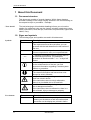
1.2. Signs and symbols
The following signs and symbols are used in this document:
Symbol
...
Symbols
...
...
– or –
...
Text formats
6
Format
Detail
Description
... identifies a requirement.
This requirement must be met before you can
proceed with the task described in this section of
the text.
... identifies a mandatory action.
You are requested to carry out a specified task.
... identifies a mandatory action to which there is
an alternative procedure. The alternative
procedure is introduced with "– or –" or by a left
indent.
... identifies general information and hints.
In the related section of the text, you find
important information regarding a certain system
feature or procedure.
... ... identifies important information.
The related information and instructions must
always be strictly followed.
... identifies a warning relating to a risk to life and
limb from electric shock.
If the instructions are not strictly adhered to,
there is an inevitable risk to life and limb.
... ... identifies a warning relating to a potential
risk or dangerous situation.
If the instructions are not adhered to, there is a
risk of death, injury or damage to property.
Description
Names of software and operating elements,
lettering on the device as well as numbers and
text shown on the display are printed in italics.
ALPTEC2333b
General Safety Instructions
2 General Safety Instructions
The design and manufacture of this device conform to the latest state of
technology and the safety standards lay down in IEC 61010-1/ 2nd edition. If
used improperly, there is a risk of damage to persons and property.
Class III
Protection class
Qualified people
Safe operation
The device may only be operated by suitably qualified personnel.
For the purpose of these instructions, all persons who are familiar with
the installation, assembly, connection, inspection of connections and
operation of the analyzer and who have completed training in at least one
of the following areas:
switching on/off, enabling, earthing and identification of electrical circuits
and devices/systems according to the applicable safety standards;
maintenance and operation of appropriate safety gear, in accordance
with the applicable safety standards;
first aid.
Proper use
Electrical
connections
Risks during
operation
Ensure that all persons using the device have read and fully
understood the operating manual and safety instructions.
The device may only be used under certain ambient conditions.
Ensure that the actual ambient conditions conform to the admissible
conditions laid down in chapter "8.5".
During operation, ensure that the cooling vents (if exist) are not
obstructed in order to prevent heat accumulation inside the housing.
Always comply with the instructions in chapter "3".
Prior ton any manipulation of the device, shut off all the electrical
sources connected to the device.
Do not use the device for any other purpose than the measuring of
voltages and currents that are within the measuring ranges and
categories, including voltage to earth, laid down in chapter "3".
Improper use shall void all warranty.
Ensure that the power and connecting cables as well as all
accessories used in conjunction with the device are in proper working
order and clean.
Ensure that the protective earth connector of the power lead is
connected according to the instructions to the low-resistance unit earth
cable.
Install the device in such a way that its power cable is accessible at all
times and can easily be disconnected.
For connection work, do not work on your own but in teams of at least
two persons.
Do not use the device, if the housing or an operating element is
damaged.
Ensure that the connected devices work properly.
In the case of a direct connection to current circuits (without
transformer or shunt), ensure that the circuit is protected to max 16 A.
General Safety Instructions
Maintenance and
repairs
Accessories
Shutting down
Do not open the housing. Do not carry out any repairs and do
not replace any component parts of the device.
Damaged connecting and power leads must be repaired or
replaced by an authorised service technician.
Damaged or defective devices may only be repaired by
authorised specialised technicians.
Only use the accessories supplied with the device or specifically
available as optional equipment for your model.
Ensure that any third-party accessories used in conjunction with
the device conform to the IEC 61010-2-031/-032 standard and
are suitable for the respective measuring voltage range.
If you detect any damage to the housing, controls, power cable,
connecting leads or connected devices, immediately disconnect
the unit from the power supply.
If you are in doubt as regards the safe operation of the device, immediately shut
down the unit and the respective accessories, secure them against inadvertent
switching on and bring them to an authorised service agent.
8
ALPTEC2333b
General dimension
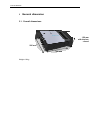
3
General dimension
3.1. Overall dimensions
152 mm
with the box
closed
295 mm
340 mm
Weight 4.8 kg.
General dimension
3.2. Size of the voltage wires :
2m
3.3. size of the current wire :
45 cm
15 cm
2m
10
ALPTEC2333b
General safety instruction
4 General safety instruction
Power supply
The power supply level shall be inside the limit indicated on the box
and the indication below :
Type:
Power Supply :
Frequency:
Protection class:
MEASUREMENT:
Nominal Voltage:
Voltage precision:
Nominal current :
Current precision:
ALPTEC2333B
L1L2 : 210-600Vac / L1N :120-345 Vac
50Hz
IP54
3 x 230V
0.1%
3 Input / Depends of the range selected (300A 100A
3000A)
1%
The battery charge begins automatically when the power is on.
Power supply from When the power shut down, the battery will automatically power the device for 1
battery
hour mini.
Input voltage
The maximum input voltage to earth ( ) may not exceed 600V CATIII.
Input current
The input current depends on the transducer. The range is from 300A to 3000A.
Servicing and
maintenance
Do not remove the cover.
Refer servicing to qualified personnel.
Conformity mark re. EC Low Voltage Directive 73/23/EEC and EMC Directive
89/336/EEC.
Protection class
IP 54
Design and functions
5 Design and functions
This chapter provides an overview of the terminals, communication ports and
interfaces of this instrument, as well as a list of display and operating devices and
a brief introduction to the basic functions of the unit.
5.1. Terminals
Mini USB plug :
This connector shall be mini USB plug Type A on one side and USB Type B on
the other side.
Warning:
Disconnect USB before the power ON.
If the connector is plugged when the device is started, disconnect the USB plug at
the PC side.
USB input
12
ALPTEC2333b
Design and functions
5.2. Display and control information
The different Leds (Power, Status, Mem and Com) enable to know the status of
the ALPTEC2333B
Led Power :
The Led Power is green when the device is “On”. When the device is « off » all
the leds are shut down.
Led Status :
The led « Status » shall blink orange when the ALPTEC2333B is on and not
connected to a periodic signal (frequency ~ 50 Hz), the color changes in green
when the ALPTEC2333b is connected at one periodic signal (it is the PLL),
frequency of the signal shall be near 50 Hz.
Led Memo :
The led « Memo » is off when there is no recording.
When this led is blinking, the sequence enables to know what is the recording
status :
25% : recording is scheduled.
50% : ALPTEC2333B is recording.
75%: recording is finished.
The Led Memo is blinking red when the ALPTEC2333B is erasing the data.
Led Com:
The Led Com is blinking orange when the ALPTEC2333B is communicating
through USB.
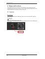
Design and functions
5.3. Switches
switch ‘ON-OFF’ :
This switch will start the ALPTEC2333B
In order to charge the battery, this switch shall be « on » and the voltage input
shall be connected to a power supply.
Switch ‘Calibre select’ : (range select)
When this switch is pressed briefly: it will change the range of the current clamp:
the corresponding led shall be on.
In order to start a record: press this switch more than 3s, the range led will be
off during one second and after on. The switch shall be relaxed, the
ALPTEC2333B will start a recording. This status is verified by the memo led
status (see previous chapter)
It is also possible to stop the recording with the same long pressure on the
switch.
Connection checking : See chapter 6.3
14
ALPTEC2333b
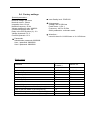
5.4. Factory settings
General parameters:
Connexion : star
Nominal voltage: 230 Vrms
Nominal current : 5Arms
Integration time: 10 min
Network frequency: 50 Hz
Voltage transformer ratio: 230/230
Current transformer ratio: 5/5
Delay in the GPS Synchro (h) : 2 h
Voltage hysteresis: 10 %
Current hysteresis: 10 %
ower Quality level : EN50160
Histogramms :
Voltage: 200 to 250Vrms
Power factor : 0,5 à 1
Frequency : 49,5 to 50,5Hz
Other parameters : automatic mode
Waveform :
record is done for U<90%Unom or U>110%Unom
Passwords:
Administrator password: 00000000
User 1 password: 00000000
User 2 password: 00000000
Ripple control:
Filter status
Applied to inputs:
Storage of the pulses
Number of pulses
Telecom n°1
( Pulsadis )
On
V1, V2, V3
On
40
On
V1, V2, V3
On
50
Frequency (Hz)
175
188
Bandwidth (Hz)
Max level low status
5
0,6
5
0,6
Min level high status
Width of the high status of the first pulse (s)
Width of the low status of the first pulse (s)
0,9
1
2,75
0,9
2
1
Width of the high status of the next pulses (s)
Width of the low status of the next pulses (s)
1
1,5
0,5
0,5
Parameter
Telecom n°2
Start-up the device
6 Start-up the device
6.1. Checking of delivery
Prior to work with the device, check the delivery to ensure that it is
complete, using the following list and the delivery specifications:
6.2. ALPTEC2333B
1 Power Quality analyzer ALPTEC2333B
1 bag with :
* 1 USB cable.
* 1 measurement cable “TRI” for Phase to Phase measurement (input L1,L2,L3,
ground and neutral measure)
* 1 measurement cable “POWER” for phase – neutral measurement (input Phase
Earth Neutral with one plug) ; This cable should be used for charging the device.
* 1 measurement cable for “VT” (input L1,L2,L3 and neutral measure and the
input from the power supply plug for a separated power supply)
* 1 current cable “CURRENT” with 3 rogowsky coils
* 1 calibration certificat
*.The user manual.
* 1 CD-ROM « WINALP2400 »
16
ALPTEC2333b
Start-up the device
6.3. Checking the connections
After connecting the voltage measurement (L1, L2, L3 and three-phase
neutral) and current measurement (I1, I2 and I3) cables to the analyzer, the
LEDs can be used to check the order of the phases:
Voltage LEDs:
If the voltage LEDs L1, L2 and L3 flash in this order and at regular intervals, the
voltage inputs have been connected correctly.
If the LEDs flash in a different order or flash erratically, the phases are inverted.
Analysing how the LEDs flash can help determining which phase is not connected
correctly.
Current LEDs:
In the same way, the current LEDs L1, L2 and L3 should flash in this order and at
regular intervals.
6.4. Supply of the internal battery
Battery:
The instrument is equipped with one internal battery
For the first use of the instrument, the battery must been duly charged.
The charge of the battery is starting as soon as the instrument is supplied through
the voltage input. The instrument will indiquate the charger status as described
below :
Just after starting, the Led "Charger Status" is during all the charging period, then
the led will turn into green at the end of the charging process (~3h).
If the device is not connected to a voltage supply, the led is green.
If the led "Charger Status" is not lighted up :
Switch off the instrument.
Check with a well calibrated multimeter if the supply source is ok.
Start-up the device
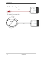
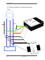
6.5. Wiring the analyzer for three-phase measurement
Source
Ground
Neutral
or ground
L1
L2
L3
Source
Load
Load
18
ALPTEC2333b
Start-up the device
Power supply/measurements:
The analyzer is powered by specific inputs ("Alim_A" – "Alim_B"). The
"POWER" single-phase or “TRI” three-phase measurement cables have
internal bridges enabling the analyzer to be powered from the
measurement inputs.
Warning:
The voltages on inputs L1, L2 and L3 must not exceed 600 V rms.
The voltage between L1 and Measurement neutral must not exceed
345 V rms.
The voltage between L1 and L2 or L2 and L3 or L3 and L1 must not exceed
600V rms.
The voltage between The Alim_A and Alim_B inputs must not exceed
345 V rms.
6.6. Single-phase measurement
The cable must have 4 internal bridges:
Use the designated cable provided “POWER”
6.7. Three-phase measurement
The cable must have two internal bridges:
Use the designated cable provided “TRI”
For correct measurements, the Measurement neutral input must be
connected to neutral or earth.
6.8. VT measurement:
For use behind high voltage transformer (VT) in substation:
Measurement input and supply of the device (dedicated 230V plug) are
separated.
Use the designated cable provided “VT”
Start-up the device
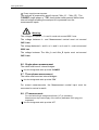
6.9. Wiring of communication ports
To establish communication between a local or remote PC and the analyzer, the
appropriate communication port and cable must be used.
The FT232BM driver, provided on the WINALP2400 CD-ROM,
will be automatically installed on the PC during the installation
of your software Winalp2400. If it has not been installed, check if FTDI
product was not already installed for a previous application. If yes, install the
usb driver manually.
The link is a USB 1.1 connection.
USB point-to-point
20
ALPTEC2333b
Start-up the device
6.10. Powering up the analyzer
Power up
Turn on the analyzer power supply circuit, then the input voltage and
current circuits.
Set the ON – OFF switch on the analyzer to the ON position.
The green “Power” LED is lit.
The “Status” LED starts flashing within 30 seconds.
Battery
The analyzer has a built-in rechargeable battery.
The battery must be charged when the analyzer is first used.
Battery charging starts as soon as the analyzer is powered up.
The “Charger Status” LED is orange throughout charging, and turns green
when the battery is fully charged (approx. 3 hours).
If the analyzer is not connected to a power supply, this LED is green.
If the “Charger Status” LED does not come on:
Turn off the analyzer.
Check the wiring between the analyzer and the power supply using a
calibrated multimeter.
Start-up the device
6.11. Installation
Before cabling the device, be sure to understand correctly the specifications
described in this section.
Installation
Follow the safety instructions regarding ambient conditions and location
of installation.
Place the device onto a clean and stable surface or mount it to the
appropriate DIN rail.
Risk to life and limb from electric shock!
Follow all the instructions of the chapter “”.
Shut off the power supply, Voltages and Currents circuits prior to
connect the device.
Never open the circuit of a current transformer. Always
bridge the inputs of the current transformer before
connecting or disconnecting the ALPTEC device.
Never bridge the circuit of a voltage transformer.
In order to ensure safe operation, first connect the device to the power supply
circuit.
Connect the voltage measurement circuits, ensuring that the maximum
measuring voltage and max. Voltage to earth are not exceeded.
Connect the current measurement circuits, ensuring that the maximum
measuring current is not exceeded.
Do not use leads and accessories that do not fulfil the relevant safety
standards, as this could lead to serious injury or death from electric shock!
22
ALPTEC2333b
First step with the software
7 First step with the software
7.1. Required hardware
Computer (PC)
Pentium IV (Minimum)
520 MB RAM (Minimum)
Serial port RS232
Ethernet Port RJ45
10 GB of free space for the hard disk
CDROM Reader (for installation)
Microsoft® Windows 98, 2000, NT, XP, VISTA
KORTEX Novafax 56000 modem
7.2. Software installation (CD-ROM)
Installation
From the CD-ROM “WINALP2400 software suite”
Follow the instructions and enter the registration key which is on the CD
jacket.
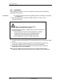
7.3. Launching the software
Login
Click on the shortcut ALPTEC 2400 manager in the WINALP2400 software suite:
the default login is “admin”; no password.
7.4. Choose the good langage
In the toolbar Outils, choose Configuration.
Then, choose the good langage and restart the application.
First step with the software
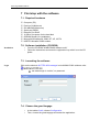
7.5. Wizard
This windows is the first windows who will appears once the program is running
The easiest way to use the software and the analyser is to follow the
indication from this wizard :
Create a new campaign : will create a campaign with the
measuring point associated and a basic configuration
Download a campaign : the software will download the data
from the instrument to the data base
See the report for a campaign : the software will create an
automatic report with the value which were recorded and
stored in the data base.
Go to Software : use this option to use all the functionalities
of the software
In order to view the windows described at the next chapter, click on Go to
Software.
24
ALPTEC2333b
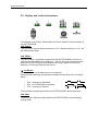
First step with the software
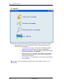
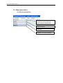
7.6. Menu description :
The different possibilities
Creation, manual download and
management of the measuring
points, customers and devices.
Analysis of the data, listing of the
graphs and reports
Downloads
Template to use in the software
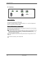
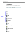
First step with the software
List of the templates
These templates avoid repeating the same setup every times.
To define the hour of
download, the instruments
For every of used modem:
Hayes command.
For every communication
between the PC and the
modem
For every communication of
the equipement
For the Quality models
(EN50160 for example)
For the description of the
ripple control
To make a personalization
of histograms
To define the triggers to
records waveforms
To define the mail and sms
parameters (and alarms)
26
ALPTEC2333b
First step with the software
7.7. Icons’ description
The associated function may change with the different windows
Icons
The description of the function:
add a new form…
Recopy the form
Common
through all
the software
Modify
Delete
display the details
Print preview
Print
Setup
Listing of the setups
Listing of the advanced setup
Real time measurement
Manual download
Reports
First step with the software
7.8. Measuring points management
The measuring point is the area where the ALPTEC is placed for measurements.
The data of the measuring point will be downloaded and added in the software
date base
Each measuring point MUST be created in WINALP2400 software
If the instrument is modified or exchanged, a new instrument is able
to be associated to the same measuring point. The data from the
new instrument will be added to the old data from the previous
instrument. Then it will be possible to have continuity for the
analysis.
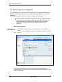
New measuring point:
Create a new
measuring point
The different steps to create a measuring point are described
below:
In the management tab, choose measuring points and the
icon : « new »
28
Then give a reference (the minimum information requested) and a
communication model (how to join the instrument) and a download model
(what to download)
ALPTEC2333b
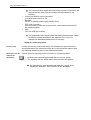
First step with the software
The communication model defines the way to join the instrument and
to download the data. Different models are still available in the
software :
Direct (port RS232 direct connection)
Just fill the port number to use
Ethernet
Fill the IP address and the port (usually 2001)
RTC (with a modem)
Give the phone number and if required the communication switch N° of
the measuring point.
USB
Fill in the USB port number
The download model explains what the data to download are. Some
models are already available in the software (Rms 10min for
example will download the data rms 10 minutes).
Setup of a measuring point:
First use only
In order to have the correct information it is mandatory to synchronies the
setup parameter of the instrument which are in the instrument memory with
the matching measuring point in the software data base
Read and write the This will be done manually after the creation of a measuring point.
setup in the
instrument
Underline the measuring point and click on the tool : setup
The windows with the setup read in the instrument will appear
The instrument is now declared and ready for a setup. If you
validate the windows it will be present in the data base.
First step with the software
30
Change the setup if necessary (change the ration for example) and at the
end click on the ‘send the configuration’ tool (the flag)
The instrument is now declared and changes are done inside the
calculation board.
ALPTEC2333b
First step with the software
Check the wirings :
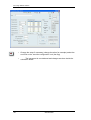
With the real time measurement it is possible to check the wirings
(direction of the current and phase order).
Winalp2400 offers different way to display the real time
measurements: RMS value, RMS table, Scope meter, symmetrical
components.
RMS table
in order to see real time display click on the icon
To change the display, click on STOP
Choose the requested display
then read the value with ‘GO’.
To stop the real time reading click on STOP
This tool offers a summary of all the important values
This will give real time RMS values:
First step with the software
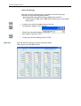
This tool is made to check the phase angle and the phase orders
The software displays the 3 voltage phase and the 3 current phase (at the
top left windows)
Symmetrical
components
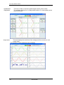
Scope meter
This tool displays the waveform of the voltage and the current as a real
scope meter.
It is possible to select 3 different ways of display.
32
ALPTEC2333b
First step with the software
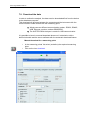
7.9. Download the data
In order to realize the analysis, the data must be downloaded first from the device
to the data base computer.
This download will be done between the computer and the instrument with the
communication model defined with the measuring point.
Winalp can use different communication modes : RS232, RS485,
USB, Ethernet, modem, modem GSM/GPRS.
The ALPTEC2333b Analyzer is made for USB communication.
It is possible to launch a manual download whenever it is desired or with a
defined schedule and the server software with the automatic download feature.
Manual download for a measuring point
In the measuring points’ list select (underline) the required measuring
point.
Click on the icon download.
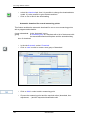
First step with the software
select the download tab, then it is possible to change the download data
model. It is also possible to give the date and time
Click on Go to launch the downloading
Automatic download for several measuring points
This feature enables the automatic download for one or more measuring points
with a programmed schedule.
In the ‘Automatic’ menu.
A download group is a template with a list of instrument with
the associated download template and the assoxiated day,
hour of download
Create a download
group
34
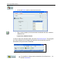
In the tab Automatic, select Download.
Click on new in order to create a new group of download.
Click on Add in order to add a measuring point.
Choose the measuring point and the required action (download, time
adjustment,…) and the requested download model.
ALPTEC2333b
First step with the software
In the tab Period, define a download schedule.
Give a name (caption) for this automatic download and save it with the
validation tool.
Launch the download server
In order to start the automatic tasks, launch the Download server. This program
as to be considered as a background task and will automatically start the
download as they have been scheduled
It is possible to change some parameters (the refresh time …) in
the tab Parameters.
Data analysis
8 Data analysis
This manual won’t give all the possibilities for the analysis. Below you will find
some example.
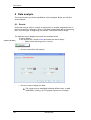
8.1. Events
One event may be a dip or a swell, an interruption or another magnitudes out of
the limit (frequency, harmonic, flicker). This data is associated with its measuring
point, its event type, its beginning, its channel, its extrmum and its length.
The different step to display the events are descibed below.
It is as a wizard :
In the analysis tab, choose Event and follow the below Steps :
Choose the dat a
Select one measuring point (or more)
Choose a period for the analysis
Choose a way to display the data.
The events may be displayed following different way : a table
(UNIPEDE), a listing, an ITIC graphs (extremum vs length)
36
ALPTEC2333b
Data analysis
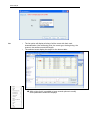
List
The list option will display a listing of all the event with their main
characterization (the measuring point, the event type, the beginning, the
channel, the extremum and the length).
The selected event display the shape on the bottom table.
With a right click it is possible to have several options to modify
some parameters and some displays.
Data analysis
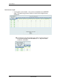
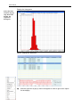
Table duration /depth
In the option ‘event sorted’ : every event is classified in an UNIPEDE
table. This table only give the number of events for a length and an
extremum.
For example a dip with duration from 0.25 s and an extremum
84,3% from nominal U will be added as « 1 » dip in the case
0.10/0.30 – 90.0/80.0.
38
ALPTEC2333b
Data analysis
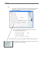
ITIC
In the option « ITIC 2000“ every data will be sorted following the duration
and the depth and represented by a point in the good abscises and
ordonate in the graph :
For example a dip of 100ms and a depth of 50 % of nominal
voltage will be displayed like this :
With the double click on the point, it is possible to display the shape of the event.
The details of the event which is selected by the mouse is given on
the top left of the representation.
Data analysis
8.2. Quality counters
The quality analyzers ALPTEC2444 record a statistical analysis for the quality of
the electricity. After the download, the data are sorted for daily, weekly or monthly
quality reports. This feature gives a summary for the power quality.
The default thresholds are defined by the EN50160 standards. It is still possible to
give your own threshold and to follow your own standards.
The conformity request is mostly limited to 95% of the time. For rms
voltage and frequency a second threshold is defined for 100% of the
time.
In the report the data are sorted by type: rms values, harmonic even and odd.
It is also possible to analyze and to sort the depth and duration table as
requested. It will create a DISDIP table.
40
ALPTEC2333b
Data analysis
Choose the data
The different step to display the quality counters are described below:
In the analyze menu, choose Quality counters
Select minimum one point
Choose an analysis period
Choose the display mode (listing or graphical)
Choose an aggregation (daily, weekly, monthly)
Choose the standard thresholds
Display of the conformity or
the no conformity of the
quality
% give the % of the total duration (day, week or month)
where the voltage was out of the limits.
Data analysis
It is also possible to display UNIPEDE table :
42
ALPTEC2333b
Data analysis
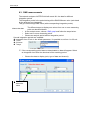
8.3. RMS measurements
The network analyzers ALPTEC2444 will record ALL the data for different
integration period.
The integration period is the period during all the RMS 200msec value (calculated
by the analyzer) are integrated.
This give one average RMS value (with corresponding integration period).
The different steps to display rms values from one or more measuring
point are described below:
In the analysis menu, choose RMS graph and follow the steps below:
Select one or more measuring points.
Choose an analysis period and an integration period.
Several integration periods are available:
Integration time:10 min is the default parameter, it’s possible to set from 1 to 60 min
1 hour
24 hours
7 days.
Choose the data
If the corresponding period was not downloaded no data will appear. Select
an integration time after the download of the matching period.
Click to
select the
value
Choose the data to display (axis, type of data and channel).
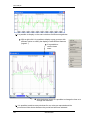
Data analysis
It is possible to display on the same windows 2 different magnitudes
With a right click it is possible to display a pop up menu with
different option to modify the display or add different features
(legend…)
It is possible to
use the lasso
zoom.
With the bottom cursor it is possible to change the time or to
change the resolution
It is possible to add as many windows for rms value as requested and the
procedure will be shorter because the period had still been selected.
44
ALPTEC2333b
Data analysis
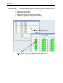
8.4. Graphical help to select the measurement
The mode ‘Data (Where, When)’ is a very interesting way to have an overview of
what is in the data base. It will display on a time based graph all the type of data
and show if the data is present or not
Choose the data
The different steps to displays the data from one or more measuring
points are described below :
In the Analysis menu choose Data (where,when) and follow the different
steps :
Select one measuring point or more.
Choose a period of analysis
Select at least one data type to display
Choose the integration period and the eventual filters
A graphical display will show all the data from the different type and
measuring points.
The quality reports which are not according the standards will be
displayed in red.
Data analysis
All the type of data are
displayed on one graph
In order to display the data select them with a lasso and with a right click
select the desired value in the pop up menu
Select the data to display
with the lasso limits for
requested period.
46
ALPTEC2333b
Data analysis
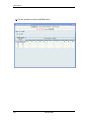
Display the histograms
Select the data
from the step by
step menu and
display the
requested
histogram
Option : display the waveform
With the right click a pop up menu will appear in order to give some option
for the display.
9 Transport and Storage
9.1. Transport
Transport the device only in its original packaging.
Keep the operating manual supplied with the device for future reference.
Protect the device during transport against heat and moisture; do not
exceed temperature range of -10 °C to + 50 °C and m ax. Humidity of 85
%.
Protect the device against impacts and loads.
9.2. Storage
Keep original packaging, as it might be required at a later stage for
transport purposes or to return the device for repairs. Only the original
packaging guarantees proper protection against mechanical impacts.
Store the device in a dry room; the temperature range of -10°C to + 50 °C
and maximum humidity of 85 % may not be exceeded.
Keep the operating manual supplied with the device for future reference.
Protect the device against direct sunlight, heat, moisture and mechanical
impacts.
10 Warranty
The warranty period for faultless operation and compliance with the specified
uncertainty of measurement is limited to 1 years from the date of purchase.
The warranty is only valid if accompanied with the respective invoice or
receipt of payment.
Not covered by warranty are damages due to improper use, overload or
operation under conditions that are outside the range of permitted ambient
conditions.
Warranty covers only technical data that is specified with a tolerance range.
Values or limits for which there are no tolerances specified are intended for
information purposes only.
11 Recalibration
ALPES TECHNOLOGIES recommends recalibrating the device every 2
years. The device can be calibrated by the ALPES TECHNOLOGIES service
department or any other calibration specialist. Refer to the Calibration
Application Note.
48
ALPTEC2333b
Maintenance
12
Maintenance
This device does not require a particular maintenance operation.
12.1. Internal items replacement
Please ask the distributor to make the internal replacement.
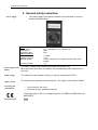
12.2. Status messages
Power Led : the led is green as the device is “On”. When the device is « Off »
all the led are « off ».
Status Led : General status of the system.
Blinking green = measure one periodic system at 50Hz.
Blinking orange = memory is full – the recording of the events is
desactived change the configuration of the events : the
actual configuration shall not be ok.
The led « Memo » is off when there is no recording.
When this le dis blinking, the sequence enables to know what is the recording
status :
25% : the recording is schedulled.
50% : the ALPTEC2333B is recording.
75%: the recording is finished.
The Led Memo is blinking red when the ALPTEC2333B is erasing the data.
Com Led :
The Led Com is blinking orange when the ALPTEC2333B is communicating
through USB.
Maintenance
12.3. Battery replacement
symptom : the device does not record anything when the supply is cut off.
Then the battery has to be replaced:
Please ask the distributor to make the internal replacement.
Battery ref: SAFT Li Ion 8.4V 2S 1P VL18650
Alpes Technologies advice to change the battery every 2 years.
Do not throw the battery in the fire.
Please ask the distributor to make the internal
replacement.
A
!u
ro
tE
e
T
x
d
n
f.y
i
If the date and time of the device is not correct even after one setting of the
hour :
the lithium battery has to be replaced:
battery ref : Lithium 3 Volts, 130 mAh. (CR1632)
the internal clock is supposed to work 10 years without replacement.
Please ask the distributor to make the internal replacement.
The warranty shall not be applied if the batteries are from other ref than the
indicated one.
12.4. Cleaning
Do not wash the device with water.
The device housing can be cleaned with an isopropanol-soaked rag.
50
ALPTEC2333b
Decommissioning and Disposal
13 Decommissioning and Disposal
13.1. Shutting down
Shut off the power supply, Voltages and Currents circuits prior to connect
the device.
Never open the circuit of a current transformer. Always bridge the inputs
of the current transformer before connecting or disconnecting the
ALPTEC device.
Never bridge the circuit of a voltage transformer.
Remove all connected devices.
Secure the unit against inadvertent switching on.
Ensure that the operating manual is kept near the device.
13.2. Recycling and disposal
Packaging
Housing
Always adhere to the applicable statutory regulations for recycling and
waste disposal.
The following licence agreements have been entered into for the disposal
of the packaging: (France).
Dimension : 340*295*152 mm
Weight : 4,8 kg
The electronic components including the power adapter, filter, plug-in
modules and wires have a weight of approx. 2500 g and a volume of
approx. 5000 cm3.
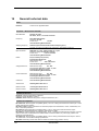
14
General technical data
EMC
Emission:
Conform to the applicable levels.
Precision – Measurement methods
Recorded data:
Average rms data.
200 msec, 10 min, 1 h and 24 h intervals.
Frequency:
45-57,5Hz (60Hz option).
Resolution: 10 mHz.
Intrinsic error:
30 mHz.
Class A following IEC-61000-4-30.
Sampling frequency:
10240 Hz synchronized with the network frequency (PLL).
Precision 10 cycles FFT (Fast Fourier Transform) – Bandwidth 30-2200 Hz.
Dips and Swells:
RMS data on 1 cycle, sliding window of ½ cycle.
Reference voltage: U nominal or average.
Intrinsic error:
<1% of U nominal.
Class A following IEC-61000-4-30.
Flicker :
Pst (10 minutes), Plt (2 hours).
Following IEC-61000-4-15.
Measurement range:
0-20.
Intrinsic error:
<5% of Unominal.
Class A following IEC-61000-4-30.
Voltage Harmonics:
Measurement range :
H2 – H51.
Recorded data: 200 msec, 10 min, 1 h, 24h.
Following IEC-61000-4-7 Class I.
Class A following IEC-61000-4-30.
Current Harmonics:
Measurement range :
H2 – H51.
Recorded data: 200 msec, 10 min, 1 h, 24h.
Following IEC-61000-4-7 Class I.
Class A following IEC-61000-4-30.
Unbalance:
Class A following IEC-61000-4-30.
Active Power:
following IEC-61036 class 2.
Reactive Power:
following IEC-61268 class 2.
Distortion Power:
following IEC-61036 class 2.
Standard references
EN 50160 “Voltage characteristics of electricity
supplied by public distribution systems”
UNIPEDE, 230.02 “Measurement guide for voltage characteristics, cat 1”.
Standards Compliance
IEC 61000-4-30 “Electromagnetic compatibility (EMC) - Part 4-30: Testing and measurement techniques - Power
quality measurement methods”
IEC 61010-1 /2001 “Safety requirements for electrical equipment for measurement, control, and laboratory use Part 1: General requirements”.
IEC 61000-4-6 “Electromagnetic compatibility (EMC) - Part 4-6: Testing and measurement techniques Immunity to conducted disturbances, induced by radio-frequency fields.”
IEC 61000-4-7 “Electromagnetic compatibility (EMC) - Part 4-7: Testing and measurement techniques - General
guide on harmonics and interharmonics measurements and instrumentation, for power supply systems and
equipment connected thereto”.
IEC 61000-4-15 “Electromagnetic compatibility (EMC) - Part 4: Testing and measurement techniques - Section
15: Flickermeter - Functional and design specifications”.
IEC 61036 “Alternating current static watt-hour meters for active energy (classes 1 and 2)“
52
ALPTEC2333b
General technical data
IEC 61268 “Alternating current static var-hour meters for reactive energy (classes 2 and 3)“
73/23/EEC EC Low Voltage Directive
89/336/EEC EMC Directive
See the “Type test” document for other standards compliance.
15 Definitions
CBEMA-Curve
ITIC-Curve
Coverage
(statistics)
Device
DISDIP
Electrical
variable
Event
Histogram
Permanent
recording
Power Quality
(PQ)
Triggered
recording
User
In 1977 the Computer and Business Equipment Manufacturers Association
provided an energy performance profile for computer equipment known as
the CBEMA curve. Revised by the Information Technology Industry
Council (ITIC) in 1996 it will continue to be referred to as the "CBEMA
Curve". It is a necessary tool in determining the immunity limits in modern
office electronic equipment. Voltage levels and durations at the equipment
terminals, within the tolerance envelope, represent acceptable energy
being Ledivered.
http://www.itic.org/technical/iticurv.pdf
See CBEMA-Curve
The percentage of available data compared to the expected available data
for a selected period of time
Any measurement equipment.
DISDIP was initially the name of workgroup of the UNIPEDE that has been
working on a classification of dips, swells and interruptions. By extension,
the name DISDIP has been given to tables that resulted from this
workgroup.
Any parameter that might be used to define the shape of an electrical
signal. This might be a long or short-term phenomenon, affecting the wave
shape or the RMS values. Ex: Harmonics, dips, flicker...
An event is a short size information provided by a PQ device. Events are
usually punctual (dip) but may coverover longer periods (EN50160 report
event). Example:
* A triggering condition was met (dip, flicker...) OR
* A report was issued (EN report, Signaling voltages...) OR
* Information from a device following an normal or abnormal behavior
(reset, clock synchronization...)
* Information provided by the software.
An histogram is a graphical representation of the evolution of a parameter
where time information is lost and focus is given on the statistical
dispersion of the parameter.
Unconditional/continuous (usually long term) temporal recording of a
variable.
The permanent recording is logged usually at a defined time interval
(typically 10 minutes, one hour...)
Any power problem manifested in voltage, current, or frequency deviation
that results in failure or misoperation of end-user equipment.
Recording that start and stop when triggering conditions are met. This type
of recording is “finite” in time, contrary to the permanent (continuous)
recordings (10-Min, statistics, User Recordings). Usually the triggering
condition encountered when an electrical variable value overshoots of a
threshold.
Is a person that will log on the system to use it. It is recommended to use
dedicated log ins for each user and to allocate permissions according to
the authority of each individual on the system. This enables traceability of
all actions and provides security at the same time.
ALPES TECHNOLOGIES
ALPTEC2333B
Right to change specification reserved /
Technische Änderungen vorbehalten /
Sous réserve de modifications /
Nos reservamos el derecho a
modificaciones técnicas sin previo aviso /
Tutti i diritti di variazione riservati
Distributor / Vertragshändler / Distributeur / Distribuidor /
Distributore
Printed in France / Gedruckt in Frankrijk / Imprimé en France / Impreso en Francia /
Stampato in Francia