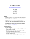
1
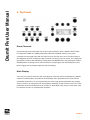
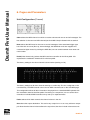
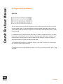
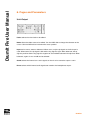
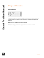
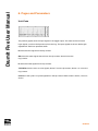
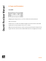
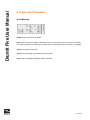
DrumIt Five User Manual
OS Version 0.36
Copyright 2box AB 2009. 2box and DrumIt Five are trademarks of 2box AB Sweden
Specifications are subject to change without prior notice.
PAGE 2
DrumIt Five User Manual
Contents
1. Introduction 4
2. Getting Started 5
3. Rear Panel 6
4. Top Panel
8
5. Editing 10
6. Pages and Parameters 11
7. Boot and OS 27
8. Signal Routing 28
9. Specifications 30
10. Glossary 31
PAGE 3
DrumIt Five User Manual
1. Introduction
DrumIt Five is an open sound drum unit featuring upto 15 independent trigger inputs, 8 audio
outputs and 4 GB Flash memory for sound storage. Together with the DrumIt Five pads and
rack stand, it becomes a complete electronic drum system giving the user an experience which
is very close to playing an acoustic drum set. However, in contrast to a traditional acoustic set,
DrumIt Five offers 100 user configurable drum kits with sounds from an ever expanding sound
library. As new sounds become available, they can easily be downloaded via USB.
The fast and flexible trigger interface offers low latency and wide dynamic range. As the sounds
consist of many velocity layers, the gradual change between soft and hard hits is faithfully
reproduced. Additionally, depending on the type of pad, different sounds can be triggered from
different zones on the pad. For example, all snare and tom pads have head and rim triggers and
all cymbal pads have cup, bow and edge triggers.
To play along with an audio track, one can download CD quality wave files or connect a media
player to the line in socket. This last one can be used as well to connect other instruments, a
microphone or a monitor mix of the other players in the band.
All DrumIt sounds are recorded with multiple microphones and then mixed down to stereo,
some with room ambience, others rather dry. Any drum channel can be loaded with any sound,
however, some sounds have multiple sound types which can only be played when the channel
is configured with an appropriate pad. Each drum sound is stored in a separate file and they are
all organized in folders to make it convenient to select them.
PAGE 4
DrumIt Five User Manual
2. Getting Started
Depending on the pads being connected, the trigger settings might have to be changed, this
is done on the Unit-Trig page. The factory trigger settings are configured for usage with DrumIt
pads. How to set up and connect these is explained in a separate manual.
Most importantly, the hihat has to be calibrated. Press the HIHAT button and then the UNIT
button. Browse to the Trigger page with the PAGEDOWN button. Loosen the hihat and let it rest
on the hihat puck. Now press the DATA button above the Pedal parameter. Finally fix the hihat at
a comfortable playing height.
For monitoring, one can either use a pair of headphones connected to the phones output or an
amplifier and speakers connected to outputs 1 and 2. The volume level for both is set with the
LEVEL knob on the top panel. The volume level for the drum channels in the mix can be set on
the Unit-Mix page, selected by pressing the UNIT button. Select the faders to be controlled by
the DATA dials by pressing one of the DATA buttons.
The kit program can be changed on the Kit-Program page, selected by pressing the KIT button.
Turning the left DATA dial will select another kit. Normally it is loaded after 1/2 second timeout
(to avoid loading all intermediate kits while selecting). One can select manual loading mode
which requires to press the left DATA button to confirm kit load (see Unit-Pref).
Use the PAGE-UP and PAGE-DOWN buttons to select other unit or kit pages. In unit mode,
all settings are saved when the UNIT or KIT button is pressed. In kit mode, one has to save
explicitly by pressing the left DATA button on the Kit-Program page. This allows to change the
name and location for the kit which is then saved by pressing the left DATA button once more.
PAGE 5
DrumIt Five User Manual
3. Rear Panel
Power
- POWER on / off button.
- AC IN for connecting the 18 V AC power adapter.
Warning! Connecting a power adapter with a voltage higher than 18 V AC or any DC
voltage might damage the DrumIt Five.
Data Ports
- USB for connecting to a USB host.
- MIDI IN and MIDI OUT for connecting to other MIDI equipment.
The USB version is 1.1 full-speed (12 Mbits / sec), compatible with USB 1.1 and 2.0 hosts. The
DrumIt Five is implemented as a standard USB Mass Storage Device, so no device drivers are
needed for the major operating systems. When connected to a host computer, the DrumIt Five
will appear as an external storage device. If the DrumIt Five is successfully connected but in
USB standby state, the host computer indicates an external storage device without storage
media.
Trigger Inputs
- KICK has a trigger function on the tip contact and a current source on the ring contact to
power a light. (optional extra at a later date)
- SNARE has trigger functions on both the tip and ring contact.
- HIHAT has a trigger function on the tip contact and special pedal control circuitry on the ring
contact.
- TOM1 to TOM4 have trigger functions on both the tip and ring contact.
- CYMB1 to CYMB3 have trigger functions on the tip contact and a switch function on the ring
contact for choke and edge detect.
PAGE 6
DrumIt Five User Manual
3. Rear Panel
The SNARE and TOM inputs can be used to connect 5 additional triggers for a total of 15
independent trigger inputs. Use a split cable (Y cable) with a stereo TRS jack on one end, to the
trigger input, and 2 mono TS jacks on the other end, to 2 separate pads. Some pads may loose
some of their functionality when connected this way. For example, the rim on a snare pad
will become inactive and the edge trigger plus choke on a cymbal pad will be disabled.
Although the secondary function on the trigger inputs can differ, any pad can be connected to
whatever trigger input jack. The secondary function of the pad might not work as expected of
course, but no damage will be done.
Audio Inputs and Outputs
- LINE IN is a stereo line level input for connecting media players, instruments or microphones.
- OUT1 to OUT6 are mono line level outputs with the ring contact to ground.
- PHONES is a stereo headphones output capable of driving headphones from 32 to 600 Ohm.
The LINE IN can be set to accept mono, stereo or balanced signals. In mono mode only the
tip signal is used, in stereo mode both the tip and the ring signal are used for left and right
respectively and in balanced mode the difference between the tip and ring signal is used,
which is then amplified by 12 or 24 dB. This last mode is intended for dynamic microphones
connected by a balanced XLR to TRS cable. Please note that a good outboard microphone
preamplifier will probably give better results and in case of microphones needing phantom
power, that will be the only option. The PHONES output is independent of the other outputs. It
can be used as 2 additional line level outputs for a total of 8 audio outputs. Use a split cable (as
described above) to obtain a left and right signal.
PAGE 7
DrumIt Five User Manual
4. Top Panel
Drum Channels
On the left side of the panel there are 10 drum channel buttons: KICK, SNARE, HIHAT, TOM1
to TOM4 and CYMB1 to CYMB3 (collectively called the CHANNEL buttons). They each
correspond to the trigger input with the same name on the rear of the unit. The names refer to
the suggested function, however the drum channel can hold any kind of sound. The 5 additional
(percussion) channels are selected by holding down the MORE button and pressing the TOM or
SNARE buttons. Pressing a drum channel button normally triggers the associated sound, this
button trigger level is programmable (see Unit-Pref-BtTrg).
Main Display
The main LCD, with the UNIT and KIT mode buttons to the left, shows 6 parameters by default,
3 below the DATA buttons and 3 above the DATA dials. Each parameter has a name with the
associated value below. For some parameters the value might appear elsewhere, this is easily
seen by context, for example the kit name appears separately on the 2nd line of the LCD. Some
parameters under the DATA buttons do not have an associated value, they are most often used
to activate a function, for example Stop and Start.
PAGE 8
DrumIt Five User Manual
4. Top Panel
Page Display
The page LCD, with the PAGE-UP and PAGE-DOWN buttons to the right, shows the current
page name in a vertically way. Since its size is restricted to 4 characters, some page names are
abbreviated.
Miscellaneous
On the top-left there is a MIDI-USB indicator. On the top-right there is a LEVEL knob controlling
the volume to the headphones output and optionally the line outputs 1 and 2.
PAGE 9
DrumIt Five User Manual
5. Editing
Editing any settings in the DrumIt Five is very straightforward. Select a mode and page, then
press a DATA button or turn a DATA dial to set the parameter value. All DrumIt Five parameters
are organized this way and can therefore easily be referenced by their mode, page and
parameter. For example Unit-Pref-Load or Kit-Drum-Tune.
Modes
The mode is selected with the UNIT or KIT button. Unit mode holds parameters relating to the
whole DrumIt Five unit and kit mode holds parameters specific to each of the 100 kits.
Pages
Each mode has several pages selected with the PAGE-UP and PAGEDOWN buttons. Some
pages hold parameters with independent values for each channel, in this case the current
channel will be lit. Press any CHANNEL button (optionally while holding down MORE) to show
the corresponding parameter values. For the first page only page-up is lit and for the last
page only page-down is lit. Switching between unit and kit mode returns to the most recently
selected page of each mode. Pressing the corresponding mode button once more, always
selects the first page.
Parameters
Each page can hold 6 parameters, 3 parameters below the DATA buttons and 3 parameters
above the DATA dials. If there is an arrow after the parameter name, one can click the DATA dial
to select the parameter value to be edited. For example, some parameters have an arrow to
indicate split data values (like a coarse and fine value), clicking the DATA dial selects between
those values. Please note that clicking the DATA dial will never change any parameter values, it
just switches the focus to another parameter or part thereof.
PAGE 10
DrumIt Five User Manual
6. Pages and Parameters
Here follows a description of all pages and parameters in the DrumIt Five unit. Note that
some pages have parameters with individual settings for each drum channel. A plus sign
after a parameter name in the description is actualy an arrow on the LCD. Please note, not all
parameters are fully functional, this will be fixed in release version 1.00.
Kit Pages
PROG Program
DRUM Drum
ENV
Envelope
SONG Song
Unit Pages
MIX
Mixer
TRIG
Trigger
CONF
Configuration
TEST Test (do not use)
VU VU
OUT Output
PREF Preferences
MIDI MIDI
PADS Pads
MEM Memory
INFO Information
PAGE 11
DrumIt Five User Manual
6. Pages and Parameters
Kit-Program (Load)
The left DATA dial selects the drum kit program. When it is turned, Load? will appear below the
left DATA button. When auto load is selected (see Unit-Pref-Load), the kit is loaded after half a
second timeout.Otherwise one can press the DATA button to load, or press the KIT button to
return to the previous program. While program load is in progress, Load! is displayed.
Time indicates the playing time for the selected song track. If no song is selected, a dash is
displayed.
Save switches to program save for editing the kit name and selecting its destination. A question
mark next to Save indicates that one or more parameters of the kit have been changed.
Stop stops the song track.
Start starts the song track.
PAGE 12
DrumIt Five User Manual
6. Pages and Parameters
Kit-Program (Save)
The left DATA dial selects the destination for the program to be saved.
Save saves the program at the selected destination and returns to program load. Press the KIT
button to return without saving.
Pos sets the cursor position.
Del deletes the character at the cursor position.
Ins inserts a character at the cursor position. As soon as the DATA dial is turned, the character
is inserted in the kit name. Click the DATA dial to increment the cursor position. The insert
character defaults to space, but when the DATA dial is turned again, it resumes from the last
character inserted. Spaces are displayed as underscores to keep the name together.
PAGE 13
DrumIt Five User Manual
6. Pages and Parameters
Kit-Drum (Channel)
Drum selects the drum sound to be triggered on this channel. The folder name is shown on the
1st line and the file name on the 2nd line. If the name includes spaces, they are displayed as
underscores to keep the name together. If the referenced sound file doesn’t exist, there will be
no folder name and there will be a ? mark instead of a sound number.
Tune adjusts the pitch of the sound. The lowest pitch is -12 half notes (one octave down), the
highest pitch is dependent on the sound encoding, upto 4 half notes is common. Click the DATA
dial to switch between 100 cent (half note) and 10 cent steps.
Vol sets the channel volume. Note that the channel volume in the mix is affected by the mix
fader as well.
The DATA buttons can trigger upto 3 different types of sound from the selected drum. For
example when a snare or tom is loaded one can trigger the head and rim sounds, for a cymbal
the cup, bow and edge sounds.
PAGE 14
DrumIt Five User Manual
6. Pages and Parameters
Kit-envelope (Channel)
Attack sets the time it takes to reach the default sound level.
Decay sets the time it takes to fade away.
Bal sets the balance for stereo sounds. Pressing the DATA button resets the balance to center,
click and turn the DATA dial to adjust the balance between left and right.
Vol sets the channel volume. This volume is duplicated on the Kit-Drum page. Click and turn the
DATA dial to adjust the balance.
PAGE 15
DrumIt Five User Manual
6. Pages and Parameters
Kit-Song
Song selects an audio track to play along with.
Time shows the total playing time (min:sec).
Vol sets the channel volume. Note that the channel volume to the mix is affected by the mix
fader as well.
Once or Loop is not implemented yet.
Stop stops the song track.
Start starts the song track.
PAGE 16
DrumIt Five User Manual
6. Pages and Parameters
Unit-Mixer
K-S-H, T-C-P and I-F-S select the 3 volume faders to be controlled by the DATA dials. The
faders are represented by the first letter of their name. Plus signs between the letters indicate
the selected faders, their full names are shown above the 3 DATA dials. The FxRet fader is not
functional yet.
Kick ... set the mix volume of one or more channels. This volume is in addition to the channel
volume as set on the Kit-Drum page. The assignment of each channel to a particular fader is
done on the Unit-Configure page. The fader names can be changed on the Unit-Out page.
PAGE 17
DrumIt Five User Manual
6. Pages and Parameters
Unit-Trigger (Channel)
Type should be set to match the connected trigger source.
Gain should be set so the hardest hit just lights up the top trigger indicator. The maximum gain
is 24 dB. From 12 dB and upwards, the threshold is automatically increased to avoid stray
triggering.
Thres should be low enough to pass weak hits, but high enough to avoid stray triggering. The
value can be set between -48 dB and -18 dB.
Curve is not functional yet.
Pedal (hihat channel only) indicates the pedal position. To calibrate the pedal, loosen the hihat
and let it rest on the hihat puck by its own weight, then press the DATA button to calibrate.
Finally set the hihat to a comfortable open position.
Choke (cymbal channels only) can be on or off, the latter in case the choke function is not
desired.
View selects 1 horizontal trigger indicator or 5 smaller vertical ones. The indicator resets
automatically after 1 1/2 second.
PAGE 18
DrumIt Five User Manual
6. Pages and Parameters
Unit-Configuration (Channel)
Chan selects the MIDI channel on which to receive and transmit note on and off messages. The
last selection is the common MIDI channel (see Unit-MIDI-Chan) indicated with an asterisk.
Note selects the MIDI note for the note on and off messages. If the associated trigger type
has more than one zone (like cup, bow and edge), the additional zones are mapped onto
consecutive higher notes. By clicking the DATA dial, one can switch between note name and
note number.
Pedal (hihat channel only) selects the MIDI continous controller for the hihat pedal. CC1
represents the modulation wheel and CC4 the foot pedal.
The factory setting for the drum channel is shown below (starting on C2).
The factory setting has all drum channels starting on a white key. The rim or edge are on the
next black key. The MIDI channel is the common MIDI channel as set on the Unit-MIDI page.
This configuration allows all drum channels to be played from a standard MIDI keyboard with
the modulation wheel as the hihat pedal. If recording on a sequencer, one can set the drum
channels on individual MIDI channels so they end up on separate tracks.
Fader selects which fader controls the channel volume in the mix.
Out selects the output destination. This can be any output from 1 to 6 or any odd-even output
pair. Note that the channel volume affects the ouput level, but the mix fader volume does not.
PAGE 19
DrumIt Five User Manual
6. Pages and Parameters
Unit-VU
The VU meters show the actual peak signal level on the audio inputs and outputs. To maintain
optimum signal quality, it is recommended to keep these signals reasonably high, however, to
avoid clipping make sure the top VU segment isn’t lit too often. Each segment on the VU meter
represents 6dB.
I~ indicates the line input signal. As the input does not have an analog level control, the output
level of the connected device must be set so the line input signal keeps below maximum. The
mode and gain of the input (mono, stereo or balanced) can be set on the Unit-Out page. The
volume level in the mix can be set on the Unit-Mix page.
1 to 6 indicate the line output 1 to 6 signals. Outputs 1 and 2 can carry the mix in which case
the volume is set with the LEVEL knob.
( ) indicates the left and right headphone signals. The volume is set with the LEVEL knob on the
top panel.
PAGE 20
DrumIt Five User Manual
6. Pages and Parameters
Unit-Output
Fader selects the mixer fader to be edited.
Name allows the fader name to be edited. Turn the DATA dial to change the character at the
cursor. Click the DATA dial to increment the cursor position.
Input can be mono, stereo or balanced. When mono, only the tip signal on the line input is
used. When stereo, the tip signal is left and the ring signal is right. When balanced, the tip
signal is positive and the ring signal is negative to accomodate balanced microphones. When
balanced, a gain of 12 or 24 dB can be selected.
Out12 selects the internal out 1 and 2 signals or the mix to be routed to output 1 and 2.
Phons selects which internal audio signals are routed to the headphones output.
PAGE 21
DrumIt Five User Manual
6. Pages and Parameters
Unit-Preferences
Load selects the options for loading a kit program. When automatic, the kit will load after half
a second timeout. When manual, one has to press Load on the Kit-Program page to load a
different kit.
Save is always on regardless of which option is selected.
BtTrg (Button Trigger) sets the button trigger level in dB. It can also be turned off.
PAGE 22
DrumIt Five User Manual
6. Pages and Parameters
Unit-Pads
The pad bar graphs show the input signal on the trigger inputs. The snare and toms have 2
input signals, one from the tip and one from the ring. The input signals are shown before gain
adjustement. Each bar represents 6 dB.
K shows the kick signal from the tip contact.
SN shows the snare signal, above S from the tip contact, above N from the
ring contact.
H shows the hihat signal from the tip contact.
T1T2T3T4 show the tom1 to tom4 signals, above T from the tip contact, above 1 to 4 from the
ring contact.
C123 show the cymb1 to cymb3 signals from the tip contact. When choke is active, a cross is
shown.
PAGE 23
DrumIt Five User Manual
6. Pages and Parameters
Unit-MIDI
PrChg (Program Change) can be on or off. This is valid for both receive and transmit.
Thru is not functional.
Local can be on or off. When off it disables the triggers to the internal sounds to avoid double
triggering when an external sequencer echos note on / off data.
Chan is the common MIDI channel on which to receive and transmit program changes and note
triggers. Each drum channel can have a different MIDI channel for note triggers (see Unit-Conf).
PAGE 24
DrumIt Five User Manual
6. Pages and Parameters
Unit-Memory
Folder shows the amount of folders.
Files shows the amount of files in all folders. This is not the same as the amount of sound files,
as it also includes the OS files plus any other files not recognized as DrumIt sound or song files.
Total is the Flash memory size.
Used is the percentage occupied by folders and files.
Free is the percentage available for folders and files.
PAGE 25
DrumIt Five User Manual
6. Pages and Parameters
Unit-Information
SerNr is the DrumIt Five serial number.
Boot is the version of the boot program.
OS is the version of the operating system.
PAGE 26
DrumIt Five User Manual
7. Boot and OS
When DrumIt Five is powered on, the LCD will show the DrumIt signature, the serial number,
the boot version and the SDRAM test. While the SDRAM is being tested, one can press one ot
the DATA buttons to choose between USB mass storage mode, OS select mode or Test mode.
If no choice is made, the default DrumIt operating system will be loaded and normal operation
begins. If the OS is not found or damaged, the unit will automatically go into USB mass storage
mode. Any errors during boot will be indicated on the lower right side of the LCD.
USB mode enables the DrumIt Five to appear as an external storage device on the host
computer. If not connected or not recoqnized by the host computer, the USB Disconnected
status will be shown. If attached properly the status will be USB Connected. One can now copy
files between the host computer and the DrumIt Five. The letters R and W indicate read and
write activity, do not disconnect during this time, as this will result in data corruption. To update
the operating system, simply copy the new DrumItXYZ.bin file (XYZ being the version number)
to the DrumIt top level folder and restart. The boot program will load the most recent version,
but to save disk space, one can delete any previous versions.
OS mode allows one to select any available version of the operating system. Press Previous or
Next to browse through all available versions, then press Load to start the selected OS. The OS
version (or any error) is shown on the lower right side of the LCD. If the OS has a serial number
license which does not match the DrumIt Five serial number, the licensed serial number will be
shown.
Test mode is for maintenance purposes only.
PAGE 27
DrumIt Five User Manual
8. Signal Routing
Inputs
There are 17 stereo sound sources:
- 15 drum channels (kick, snare, hihat, 4 toms, 3 cymbals plus 5 rim / percussion channels),
- 1 song track,
- 1 line input.
All 15 trigger input signals can be monitored on the Unit-Pads page. The line input level can be
monitored on the Unit-VU page.
Outputs
There are 7 audio outputs:
- 6 mono outputs (or 3 stereo pairs),
- 1 stereo headphones output.
All 7 audio output signals can be monitored on the Unit-VU page.
Each drum channel is routed to 1 of the 6 mono outputs (or 3 stereo pairs) and to the mixer. The
mixer consists of 9 faders of which the first 6 set the drum channel volumes and the remaining
3 set the line input, effect return (not functional yet) and song track volumes. Each drum channel
can be freely assigned to 1 of the first 6 faders. Each fader controls the mix volume of all
channels assigned to that particular fader. So, for example, one fader can change all tom levels
while preserving their levels with respect to each other. The first 6 faders can also be given a
name to reflect the type of sounds they control.
PAGE 28
DrumIt Five User Manual
8. Signal Routing
Schematic
Here below is a schematic of the signal routing. The main parameters are described with a
letter and the page on which to find them. The assignment of a channel to a particular output
(or output pair) and mix fader is programmable, the illustration below just shows one possible
setup. The mix is routed to the phones and by default to outputs 1 and 2 as well. Note that most
parameters are common to all kits (all those on Unit pages), so the signal routing from trig inputs
to audio outputs is equal for all kits.
Parameter
Page
P
pad signal Unit-Pads
Unit-Pads
T
trigger Unit-Trig
Unit-Trig
D
drum Kit-Drum Kit-Drum
C
channel volume Kit-Drum
Kit-Drum
S
song track Kit-Song
Kit-Song
I
input setting Unit-Out
Unit-Out
O
out select Unit-Conf
Unit-Conf
F
fader Unit-Mix
Unit-Mix
M
mix volume (Level knob)
(Level knob)
X
mix to out1,2 Unit-Out
Unit-Out
V
VU meter Unit-VU
Unit-VU
PAGE 29
DrumIt Five User Manual
9. Specifications
- 10 dual-function trigger inputs (1/4” TRS)
- 1 stereo audio line input (1/4” TRS)
- 6 mono audio line outputs (1/4” TS)
- 1 stereo headphones output (1/4” TRS)
- USB 1.1 full-speed
- MIDI in and out
- 20 x 4 character LCD
- 18 push buttons
- 3 rotary dials
- 1 volume knob
- 4 GB Flash memory
- 18 V AC external power supply
PAGE 30
DrumIt Five User Manual
10. Glossary
dB deciBell
VU Volume Unit
AC Alternating Current
DC Direct Current
LED Ligth Emitting Diode
LCD Liquid Crystal Display
TS Tip Sleeve connector (tip = signal, sleeve = ground)
TRS Tip Ring Sleeve con. (tip = left/hot, ring = right/cold, sleeve = gnd)
XLR Balanced audio connector (1 = ground, 2 = hot, 3 = cold)
USB Universal Serial Bus
MIDI Musical Instrument Digital Interface
PAGE 31
Copyright 2box AB 2009. 2box and DrumIt Five are trademarks of 2box AB Sweden
Specifications are subject to change without prior notice.
PAGE 32