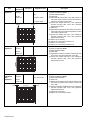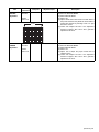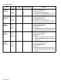
1
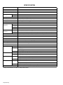
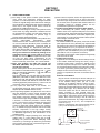
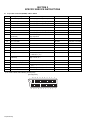
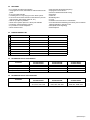
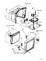
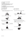
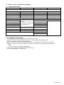
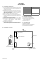
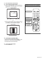
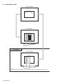
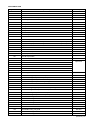
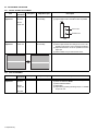
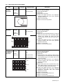
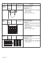
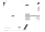
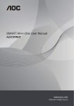
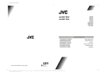
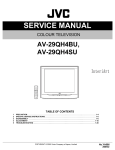
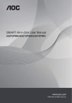
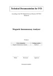
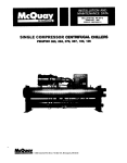
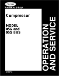
SERVICE MANUAL
COLOUR TELEVISION
52137
9
2003
AV-28KT1BUF/A, /B, /C,
AV-28KT1SUF/A, /B, /C
RM-C1100 TV
TABLE OF CONTENTS
1
2
3
4
5
PRECAUTION. . . . . . . . . . . . . . . . . . . . . . . . . . . . . . . . . . . . . . . . . . . . . . . . . . . . . . . . . . . . . . . . . . . . . . . . . 1-3
SPECIFIC SERVICE INSTRUCTIONS . . . . . . . . . . . . . . . . . . . . . . . . . . . . . . . . . . . . . . . . . . . . . . . . . . . . . . 1-4
DISASSEMBLY . . . . . . . . . . . . . . . . . . . . . . . . . . . . . . . . . . . . . . . . . . . . . . . . . . . . . . . . . . . . . . . . . . . . . . . 1-6
ADJUSTMENT . . . . . . . . . . . . . . . . . . . . . . . . . . . . . . . . . . . . . . . . . . . . . . . . . . . . . . . . . . . . . . . . . . . . . . . 1-10
TROUBLESHOOTING . . . . . . . . . . . . . . . . . . . . . . . . . . . . . . . . . . . . . . . . . . . . . . . . . . . . . . . . . . . . . . . . . 1-23
COPYRIGHT © 2003 VICTOR COMPANY OF JAPAN, LIMITED
No.52137
2003/9
SPECIFICATION
Items
Contents
Dimensions ( W × H × D )
76cm × 57cm × 47.3cm
Mass
33kg
TV RF System
Colour System
B/G, D/K, L/L'
TV Mode
PAL / SECAM
Video Mode PAL / SECAM / NTSC 3.58 / NTSC 4.43
Sound System
NICAM / A2 (Germany system)
Teletext System
FLOF (Fastext) / TOP (German system)
Tuning System
Frequency synthesizer tuning system
Number of CH memory position
100 ch
Receiving
Frequency
VHF Low
46.25MHz ~ 168.25MHz
VHF High
175.25MHz ~ 463.25MHz
UHF
471.25MHz ~ 863.25MHz
CATV
S01-S41 & S75-S79
VIF
38.9MHz (B/G, D/K, L) / 33.9MHz (L')
Intermediate
Frequency
SIF
33.4MHz (5.5MHz:B/G) / 32.9MHz (6.0MHz:D/K) / 32.4MHz (6.5MHz:L) / 40.4MHz (6.5MHz:L')
Colour Sub Carrier Frequency
PAL (4.43MHz), SECAM (4.43MHz), NTSC (3.58MHz/4.43MHz)
Power Input
AC220V ~ AC240V, 50Hz
Power Consumption
120W(Max), 3W(Standby)
Aerial Input Terminal
75Ω unbalanced, coaxial
Picture Tube
Visible size : 66cm (Measured diagonally)
High Voltage
30kV
Speaker
Main:5.7cm × 16cm oval type × 2
Audio Output
Input
10W + 10W
Video
1V(p-p) 75Ω
S-Video
Y : 1V(p-p) positive
C : 0.286V(p-p)
Output
Input Terminal
Audio (L/R)
500mV(rms) (-4dBs), High impedance (RCA pin jack × 2)
Video
1V(p-p) 75Ω
Audio (L/R)
500mV(rms), Low Impedance
Rear Side
EXT-1 (Video / Audio / RGB)
Right Side
EXT-3 (Video / Audio)
Rear Side
EXT-1 (Video / Audio)
EXT-2 (Video / Audio / RGB / S-VHS)
Output Terminal
EXT-2 (Video / Audio)
Right Side
Remote Control Unit
Headphone Jack (Stereo mini jack Ø3.5mm × 1)
VE-30017763 (RM-C1100), (AA/R06 dry battery × 2)
Design & specifications are subject to change without notice.
1-2 (No.52137)
SECTION 1
PRECAUTION
1.1
SAFETY PRECAUTIONS
(1) The design of this product contains special hardware,
many circuits and components specially for safety
purposes. For continued protection, no changes should be
made to the original design unless authorized in writing by
the manufacturer. Replacement parts must be identical to
those used in the original circuits. Service should be
performed by qualified personnel only.
(2) Alterations of the design or circuitry of the products should
not be made. Any design alterations or additions will void
the manufacturer's warranty and will further relieve the
manufacturer of responsibility for personal injury or
property damage resulting therefrom.
(3) Many electrical and mechanical parts in the products have
special
safety-related
characteristics.
These
characteristics are often not evident from visual inspection
nor can the protection afforded by them necessarily be
obtained by using replacement components rated for
higher voltage, wattage, etc. Replacement parts which
have these special safety characteristics are identified in
the parts list of Service manual. Electrical components
having such features are identified by shading on the
schematics and by (
) on the parts list in Service
manual. The use of a substitute replacement which does
not have the same safety characteristics as the
recommended replacement part shown in the parts list of
Service manual may cause shock, fire, or other hazards.
(4) Don't short between the LIVE side ground and
ISOLATED (NEUTRAL) side ground or EARTH side
ground when repairing.
Some model's power circuit is partly different in the GND.
The difference of the GND is shown by the LIVE : ( ) side
GND, the ISOLATED (NEUTRAL) : (
) side GND and
EARTH : ( ) side GND.
Don't short between the LIVE side GND and ISOLATED
(NEUTRAL) side GND or EARTH side GND and never
measure the LIVE side GND and ISOLATED (NEUTRAL)
side GND or EARTH side GND at the same time with a
measuring apparatus (oscilloscope etc.). If above note will
not be kept, a fuse or any parts will be broken.
(5) If any repair has been made to the chassis, it is
recommended that the B1 setting should be checked or
adjusted (See B1 POWER SUPPLY check).
(6) The high voltage applied to the picture tube must conform
with that specified in Service manual. Excessive high
voltage can cause an increase in X-Ray emission, arcing
and possible component damage, therefore operation
under excessive high voltage conditions should be kept to
a minimum, or should be prevented. If severe arcing
occurs, remove the AC power immediately and determine
the cause by visual inspection (incorrect installation,
cracked or melted high voltage harness, poor soldering,
etc.). To maintain the proper minimum level of soft X-Ray
emission, components in the high voltage circuitry
including the picture tube must be the exact replacements
or alternatives approved by the manufacturer of the
complete product.
(7) Do not check high voltage by drawing an arc. Use a high
voltage meter or a high voltage probe with a VTVM.
Discharge the picture tube before attempting meter
connection, by connecting a clip lead to the ground frame
and connecting the other end of the lead through a 10kΩ
2W resistor to the anode button.
(8) When service is required, observe the original lead dress.
Extra precaution should be given to assure correct lead
dress in the high voltage circuit area. Where a short circuit
has occurred, those components that indicate evidence of
overheating should be replaced. Always use the
manufacturer's replacement components.
(9) Isolation Check (Safety for Electrical Shock Hazard)
After re-assembling the product, always perform an
isolation check on the exposed metal parts of the cabinet
(antenna terminals, video/audio input and output terminals,
Control knobs, metal cabinet, screw heads, earphone jack,
control shafts, etc.) to be sure the product is safe to operate
without danger of electrical shock.
a) Dielectric Strength Test
The isolation between the AC primary circuit and all metal
parts exposed to the user, particularly any exposed metal
part having a return path to the chassis should withstand a
voltage of 3000V AC (r.m.s.) for a period of one second. (. .
. . Withstand a voltage of 1100V AC (r.m.s.) to an appliance
rated up to 120V, and 3000V AC (r.m.s.) to an appliance
rated 200V or more, for a period of one second.)
This method of test requires a test equipment not generally
found in the service trade.
b) Leakage Current Check
Plug the AC line cord directly into the AC outlet (do not use
a line isolation transformer during this check.). Using a
"Leakage Current Tester", measure the leakage current
from each exposed metal part of the cabinet, particularly
any exposed metal part having a return path to the chassis,
to a known good earth ground (water pipe, etc.). Any
leakage current must not exceed 0.5mA AC (r.m.s.).
However, in tropical area, this must not exceed 0.2mA AC
(r.m.s.).
Alternate Check Method
Plug the AC line cord directly into the AC outlet (do not
use a line isolation transformer during this check.). Use
an AC voltmeter having 1000Ω per volt or more
sensitivity in the following manner. Connect a 1500Ω
10W resistor paralleled by a 0.15µF AC-type capacitor
between an exposed metal part and a known good earth
ground (water pipe, etc.). Measure the AC voltage
across the resistor with the AC voltmeter. Move the
resistor connection to each exposed metal part,
particularly any exposed metal part having a return path
to the chassis, and measure the AC voltage across the
resistor. Now, reverse the plug in the AC outlet and
repeat each measurement. Any voltage measured must
not exceed 0.75V AC (r.m.s.). This corresponds to
0.5mA AC (r.m.s.).
However, in tropical area, this must not exceed 0.3V AC
(r.m.s.). This corresponds to 0.2mA AC (r.m.s.).
AC VOLTMETER
(HAVING 1000 /V,
OR MORE SENSITIVITY)
0.15 F AC-TYPE
1500
10W
PLACE THIS PROBE
ON EACH EXPOSED
METAL PART
GOOD EARTH GROUND
(No.52137)1-3
SECTION 2
SPECIFIC SERVICE INSTRUCTIONS
2.1
21-pin Euro connector (SCART) : EXT-1 / EXT-2
Pin No.
Signal Designation
Matching Value
EXT-1
EXT-2
1
AUDIO R output
500mV(rms) (Nominal), Low impedance Used
Used
2
AUDIO R input
500mV(rms) (Nominal), High impedance Used (R1)
Used (R2)
3
AUDIO L output
500mV(rms) (Nominal), Low impedance Used
Used
4
AUDIO GND
---
Used
Used
5
GND (B)
---
Used
Used
6
AUDIO L input
500mV(rms) (Nominal), High impedance Used (L1)
Used (L2)
7
B input
700mV(B-W), 75 Ω
Used
Used
8
FUNCTION SW
(SLOW SW)
Low : 0V-3V, High : 8V-12V,
High impedance
Used
Used
9
GND (G)
---
Used
Used
10
SCL / T-V LINK
---
Not used
Used (SCL / TV-LINK)
11
G input
700mV(B-W), 75 Ω
Used
Used
12
SDA3
---
Not used
Not used
13
GND (R)
---
Used
Used
14
GND (YS)
---
Used
Used
15
R / C input
R : 700mV(B-W), 75 Ω
C : 300mV(P-P), 75 Ω
Used (R)
Used (C2/R)
16
Ys input
(FAST SW)
Low : 0V-0.4V, 75 Ω
High : 1V-3V, 75 Ω
Used
Used
17
GND (VIDEO output)
---
Used
Used
18
GND (VIDEO input)
---
Used
Used
19
VIDEO output
1V(P-P) (Negative sync), 75 Ω
Used
Used
20
VIDEO / Y input
1V(P-P) (Negative sync), 75 Ω
Used
Used
21
COMMON GND
---
Used
Used
(P-P= Peak to Peak, B-W= Blanking to white peak)
[Pin assignment]
20
21
1-4 (No.52137)
18 16
19 17
14
15
12
13
11
10
8
9
6
7
4
5
2
3
1
2.2
FEATURES
• It is a remote controlled color television.
• 100 programs from VHF, UHF bands or cable channels can be
preset.
• It can tune cable channels.
• Controlling the TV is very easy by its menu driven system.
• It has two Euroconnector sockets for external device (such as
video recorder, video games, audio set, etc.)
• Side AV Input (EXT-3) available.
• Stereo sound systems (German + Nicam) are available.
• Full function Teletext (Fastext, Toptext).
• It is possible to connect headphone.
• Direct channel access.
2.3
APS (Automatic Programming System).
All programs can be named.
Forward or backward automatic tuning.
Sleep timer.
Child Lock.
Blue Background
T-V Link
Automatic sound mute when no transmission.
5 minutes after the broadcasting (close down), the TV switches
itself automatically to stand-by mode.
• WSS (Wide Screen Signaling)
• NTSC Playback.
MAIN DIFFERENCE LIST
Part Name
2.4
•
•
•
•
•
•
•
•
•
AV-28KT1BUF
AV-28KT1SUF
MODEL COLOUR
BLACK MODEL
SILVER MODEL
FRONT CABINET
VE-20121492
VE-20119985
BACK COVER
VE-20121494
VE-20111863
BACK DOOR
VE-20108124
VE-20120043
FUNCTION BUTTON
VE-20091798
VE-20096498
POWER BUTTON
VE-20111864
VE-20120046
JVC LOGO
VE-40013592
VE-40013593
CARTON BOX
VE-50038917
VE-50038907
DIFFERENCE LIST BY ELECTRONICS
Part Name
MAIN PWB
AV-28KT1BUF/A
AV-28KT1SUF/A
AV-28KT1BUF/B
AV-28KT1SUF/B
AV-28KT1BUF/C
AV-28KT1SUF/C
VE-20120604
VE-20127801
VE-20127796
IC500 (MI-COM)
VE-20139901
VE-20137151
VE-20139902
IC502 (MEMORY)
VE-20120610
VE-20134092
VE-20126318
AV-28KT1BUF/A
AV-28KT1SUF/A
AV-28KT1BUF/B
AV-28KT1SUF/B
AV-28KT1BUF/C
AV-28KT1SUF/C
ENG, GER, FRE, ITA
SPA, DUT, POR, TUR
ENG, GER, FRE, SWE
NOR, DAN, FIN, GRE
ENG, GER, CZE, POL
HUN, BUL, ROM, CRO
2.5
DIFFERENCE LIST BY OSD LANGUAGE
Part Name
OSD LANGUAGES
(No.52137)1-5
SECTION 3
DISASSEMBLY
3.1
DISASSEMBLY PROCEDULE
3.1.1
(1)
(2)
(3)
(4)
REMOVING THE REAR COVER
Unplug the power cord.
Remove the 8 screws [A] as shown in the Fig. 1.
Remove the 4 screws [B].
Withdraw the REAR COVER toward you.
3.1.2 REMOVING THE BACK DOOR
• Remove the REAR COVER
(1) Remove the 2 screws [C].
(2) Withdraw the BACK DOOR toward you.
3.1.9 CHECKING THE PW BOARD
• To check the back side of the PW Board.
(1) Pull out the PW Board. (Refer to REMOVING THE MAIN
PWB).
(2) Erect the PW Board vertically so that you can easily check
the back side of the PW Board.
3.1.3 REMOVING THE SPEAKER
• Remove the REAR COVER.
(1) Remove the 4 screws [I], and remove the SPEAKER.
(2) Remove the other hand SPEAKER in the same steps.
3.1.10 CAUTION
• When erecting the PW Board, be careful so that there will be
no contacting with other PW Board.
• Before turning on power, make sure that the wire connector is
properly connected.
• When conducting a check with power supplied, be sure to
confirm that the CRT EARTH WIRE (BRAIDED ASS'Y) is
connected to the CRT SOCKET PW board.
3.1.4 REMOVING THE MAIN PWB
• Remove the REAR COVER.
• Remove the BACK DOOR.
(1) Remove the 4 screws [D].
(2) Slightly raise the both sides of the MAIN PWB by hand and
withdraw the MAIN PWB backward.
3.1.11 WIRE CLAMPING AND CABLE TYING
(1) Be sure to clamp the wire.
(2) Never remove the cable tie used for tying the wires
together.
Should it be inadvertently removed, be sure to tie the wires
with a new cable tie.
CAUTION:
If necessary, take off the wire clamp, connectors etc.
Be careful enough when developing a MAIN PWB.
3.1.5 REMOVING THE SIDE CONTROL PWB
• Remove the REAR COVER.
(1) Remove the 4 screws [E].
(2) Remove the SIDE PWB.
3.1.6 REMOVING THE BASE
• Remove the REAR COVER.
(1) Remove the 2 screws [F].
(2) Remove the BASE.
NOTE:
Work after fixing so that a CRT screen may be placed upside
down or it may not fall.
3.1.7 REMOVING THE POWER SWITCH PWB
• Remove the REAR COVER.
• Remove the BASE.
(1) Remove the 2 screws [G], and remove the POWER
SWITCH PWB.
3.1.8 REMOVING THE LED PWB
• Remove the REAR COVER.
• Remove the BASE.
• Remove the POWER SWITCH PWB.
(1) Remove the 2 screws [H], and remove the LED PWB.
1-6 (No.52137)
REAR COVER
D
x4
x4
B
MAIN PWB
A
x8
C x2
BACK DOOR
BASE
F x2
CRT SOCKET PWB
x4
I
SPEAKER
SIDE CONTROL
PWB
E x4
x4
I
LED PWB
G x2
H x2
POWER SWITCH PWB
Fig.1
(No.52137)1-7
3.2
REPLACEMENT OF CHIP COMPONENT
3.2.1 CAUTIONS
(1) Avoid heating for more than 3 seconds.
(2) Do not rub the electrodes and the resist parts of the pattern.
(3) When removing a chip part, melt the solder adequately.
(4) Do not reuse a chip part after removing it.
3.2.2 SOLDERING IRON
(1) Use a high insulation soldering iron with a thin pointed end of it.
(2) A 30w soldering iron is recommended for easily removing parts.
3.2.3 REPLACEMENT STEPS
1. How to remove Chip parts
2. How to install Chip parts
[Resistors, capacitors, etc.]
[Resistors, capacitors, etc.]
(1) As shown in the figure, push the part with tweezers and
alternately melt the solder at each end.
(1) Apply solder to the pattern as indicated in the figure.
(2) Grasp the chip part with tweezers and place it on the
solder. Then heat and melt the solder at both ends of the
chip part.
(2) Shift with the tweezers and remove the chip part.
[Transistors, diodes, variable resistors, etc.]
[Transistors, diodes, variable resistors, etc.]
(1) Apply extra solder to each lead.
SOLDER
(1) Apply solder to the pattern as indicated in the figure.
(2) Grasp the chip part with tweezers and place it on the
solder.
(3) First solder lead A as indicated in the figure.
SOLDER
(2) As shown in the figure, push the part with tweezers and
alternately melt the solder at each lead. Shift and remove
the chip part.
A
B
C
(4) Then solder leads B and C.
A
B
NOTE :
After removing the part, remove remaining solder from the
pattern.
1-8 (No.52137)
C
3.3
SETTING OF THE LAST MEMORY FOR SHIPMENT
3.3.1 USER SETTING VALUES
Setting Item
Setting Value
Setting Item
SOUND MENU
BALANCE
Setting Value
FEATURE MENU
CENTER
SLEEP TIMER
OFF
BASS
CENTER
CHILD LOCK
OFF
TREBLE
CENTER
LANGUAGE
ENGLISH
HYPER SOUND
OFF
EXT-2 OUTPUT
TV
BLUE BACKGROUND
ON
PICTURE MENU
BRIGHTNESS
CONTRAST
COLOUR
SHARPNESS
These adjust are automatically
restored when A.P.S. bit in Service
menu is set.
The procedure for setting APS
bit is described bellow.
HUE (only NTSC)
INSTALL. MENU
PROGRAMME
Refer to instruction book
BAND
CHANNEL
STANDARD
PICTURE MODE
USER
COLOUR SYSTEM
COLOUR TEMP
NORMAL
DECODER (EXT-2)
ZOOM
AUTO
FINE TUNING
SEARCH
STORE
3.3.2 SETTING A.P.S. (AUTO STORE)
(1) Press [MENU] key on the remote control unit to display the main menu.
(2) Press [/] keys to select PROGRAM item, them [/] keys to display the PROGRAM menu.
(3) Press the [BLUE] key to enter the AUTOSTORE mode.
(4) Press [/] keys to choose the COUNTRY, then press [/] keys the choose country you are nou located.
(5) Press [/] keys to choose the CONTINUE, then press [] key to start A.P.S. The following message appears.
NOTE:
To cancel the A.P.S., press the [STANDARD] key.
(6) After A.P.S. is finalized, the PROGRAM menu appears again.
(7) Press [STANDARD] key to exit main menu.
(No.52137)1-9
SECTION 4
ADJUSTMENT
4.1
ADJUSTMENT PREPARATION
(1) You can make the necessary adjustments for this unit with
either the Remote Control Unit or with the adjustment tools
and parts as given below.
(2) Adjustment with the Remote Control Unit is made on the
basis of the initial setting values, however, the new setting
values which set the screen to its optimum condition may
differ from the initial settings.
(3) Make sure that AC power is turned on correctly.
(4) Turn on the power for set and test equipment before use,
and start the adjustment procedures after waiting at least
30 minutes.
(5) Unless otherwise specified, prepare the most suitable
reception or input signal for adjustment.
(6) Never touch any adjustment parts which are not specified
in the list for this adjustment - variable resistors,
transformers, condensers, etc.
(7) Presetting before adjustment.
Unless otherwise specified in the adjustment instructions,
preset the following functions with the remote control unit:
Setting Item
Setting value
BRIGHTNESS
CENTER
CONTRAST
COLOUR
SHARPNESS
COLOUR TEMP
ZOOM
4.2
AUTO
MEASURING EQUIPMENT
(1) DC voltmeter (or digital voltmeter)
(2) Signal generator (Pattern generator)
[PAL / SECAM / NTSC]
(3) Remote control unit
4.3
ADJUSTMENT ITEM
• SCREEN ADJUSTMENT
• DEFLECTION CIRCUIT ADJUSTMENT
• WHITE BALANCE ADJUSTMENT
4.4
ADJUSTMENT LOCATIONS
FRONT
IC500 (MI-COM)
TOP
IC502 (MEMORY)
MAIN PWB
HEADPHONE
MENU
P/Ch
VIDEO
FBT
SIDE CONTROL PWB
TUNER
TU200
1-10 (No.52137)
UPPER : FOCUS
LOWER : SCREEN
4.5
BASIC OPERATION OF SERVICE MENU
4.5.1 HOW TO ENTER THE SERVICE MENU
(1) Press the [INFORMATION] key and [MUTING] key
simultaneously in the main menu, and the SERVICE
MENU screen (Fig.1) will be displayed.
REMOTE CONTROL UNIT key NAME
SERVICE MENU
MUTING key
SERVICE
ADJUST...
OPTIONS...
AK45JA***
AK45JA***
INFORMATION key
Select for adjustment
Do not adjust
Fig.1
(2) While the SERVICE MENU screen is displayed, press the
[/] and [/] key and select the "ADJUST...", then
ADJUST MENU sucreen (Fig.2) will be displayed.
ADJUST MENU
MENU key
UP / DOWN
[
] key
LEFT / RIGHT
[
] key
ADJUST...
000
001
002
003
004
005
006
007
008
009
***
***
***
***
***
***
***
***
***
***
SETTING ITEM No.
SETTING VALUE
Fig.2
4.5.2 SELECTION OF ADJUSTMENT ITEMS
(1) Enter the SERVICE MENU and select ADJUST.
(2) Press the [/] key and select the ADJUSTMENT ITEM.
(3) Press the [/] key and set the SETTING VALUE.
(4) Changed values are stored automatically.
4.5.3 HOW TO EXIT SERVICE MODE
(1) Press the [MENU] key.
(No.52137)1-11
4.5.4 SERVICE MENU SCREEN
SERVICE MENU
SERVICE
ADJUST...
OPTIONS...
AK45JA***
AK45JA***
ADJUST MENU
ADJUST...
000
001
002
003
004
005
006
007
008
009
***
***
***
***
***
***
***
***
***
***
SETTING ITEM No.
000~143
SETTING VALUE
Do Not Adjust
OPTIONS MENU
OPTIONS..
000
001
002
003
004
005
006
007
008
009
**
**
**
**
**
**
**
**
**
**
********
********
********
********
********
********
********
********
********
********
SETTING ITEM No.
000~063
SETTING VALUE
NOTE:
Do not adjust the OPTIONS MENU. If you change the setting value, the set will not function correctly.
1-12 (No.52137)
ADJUSTMENT ITEM
adjustment No.
adjustment part
description
000
White Point RED
Not used
001
White Point GREEN
Not used
002
Whit Point BLUE
Not used
003
AGC (Automatic Gain Control)
004
IF-PLL Negative
Not used
005
IF-PLL Positive
Not used
006
Y-Delay
007
Y-Delay SECAM
008
Y-Delay NTSC
009
Y-Delay OTHER
010
Vertical Position Offset
Not used
Fixed
011
Vertical Amplitude Offset
Fixed
012
Horizontal Position Offset
Fixed
013
Horizontal Amplitude Offset
Fixed
014
Vertical Blank Start (It will be used only at 4:3 tube for 16:9 mode adjustment)
015
Vertical Blank Stop (It will be used only at 4:3 tube for 16:9 mode adjustment)
016
Angle
017
Bow
018
4:3 Horz. Blank Start
Do not adjust
019
4:3 Horz. Blank Stop
Do not adjust
020
EHTV compensation
021
EHTTM compensation
022
EHTEW compensation
023
WDR
024
WDG
025
WDB
026
CR
027
CG
028
CB
029
COR coring level
030
REGULAR VERT_POS (Vertical Position)
031
REGULAR VERT_AMPL (Vertical Amplitude)
032
REGULAR VERT_SCOR (Vertical S Correction)
033
REGULAR VERT_SSYM (Vertical S Symmetry)
034
REGULAR TRAPEZE
035
REGULAR CUSHION
036
REGULAR HOR_COR_SYM(Horizontal Corner Symmetry)
037
REGULAR HOR_CORNER (Horizontal Corner)
038
REGULAR HORZ_POS (Horizontal Position)
039
REGULAR HORZ_AMPL (Horizontal Amplitude)
040
PANORAMIC VERT_POS
Video processor
adjust itself.
Not used
041
PANORAMIC VERT_AMPL
Not used
042
PANORAMIC VERT_SCOR
Not used
043
PANORAMIC VERT_SSYM
Not used
044
PANORAMIC TRAPEZE
Not used
045
PANORAMIC CUSHION
Not used
046
PANORAMIC HOR_COR_SYM
Not used
047
PANORAMIC HOR_CORNER
Not used
048
PANORAMIC HORZ_POS
Not used
(No.52137)1-13
adjustment No.
adjustment part
description
049
PANORAMIC HORZ_AMPL
Not used
050
14:9 ZOOM VERT_POS
Not used
051
14:9 ZOOM VERT_AMPL
Not used
052
14:9 ZOOM VERT_SCOR
Not used
053
14:9 ZOOM VERT_SSYM
Not used
054
14:9 ZOOM TRAPEZE
Not used
055
14:9 ZOOM CUSHION
Not used
056
14:9 ZOOM HOR_COR_SYM
Not used
057
14:9 ZOOM HOR_CORNER
Not used
058
14:9 ZOOM HORZ_POS
Not used
059
14:9 ZOOM HORZ_AMPL
Not used
060
16:9 ZOOM VERT_POS
Not used
061
16:9 ZOOM VERT_AMPL
Not used
062
16:9 ZOOM VERT_SCOR
Not used
063
16:9 ZOOM VERT_SSYM
Not used
064
16:9 ZOOM TRAPEZE
Not used
065
16:9 ZOOM CUSHION
Not used
066
16:9 ZOOM HOR_COR_SYM
Not used
067
16:9 ZOOM HOR_CORNER
Not used
068
16:9 ZOOM HORZ_POS
Not used
069
16:9 ZOOM HORZ_AMPL
Not used
070
16:9 ZOOM SUBTITLE VERT_POS
Not used
071
16:9 ZOOM SUBTITLE VERT_AMPL
Not used
072
16:9 ZOOM SUBTITLE VERT_SCOR
Not used
073
16:9 ZOOM SUBTITLE VERT_SSYM
Not used
074
16:9 ZOOM SUBTITLE TRAPEZE
Not used
075
16:9 ZOOM SUBTITLE CUSHION
Not used
076
16:9 ZOOM SUBTITLE HOR_COR_SYM
Not used
077
16:9 ZOOM SUBTITLE HOR_CORNER
Not used
078
16:9 ZOOM SUBTITLE HORZ_POS
Not used
079
16:9 ZOOM SUBTITLE HORZ_AMPL
Not used
080
OSD Position
081
BCLTHR Beam current threshold
082
BCLG Beam current loop gain
083
ROTATION (TILT)
084
LSLSA Luma soft limiter
Fixed
085
LSLSB Luma soft limiter
Fixed
086
LSL2 Luma soft limiter
Fixed
087
LSLTA Luma soft limiter
Fixed
088
LSLTB Luma soft limiter
Fixed
089
REFERENCE WDR RED (NORMAL)
090
REFERENCE WDR GREEN (NORMAL)
091
REFERENCE WDR BLUE (NORMAL)
092
REFERENCE CUTOFF RED
093
REFERENCE CUTOFF GREEN
Fixed
094
REFERENCE CUTOFF BLUE
Fixed
095
IBRM
096
WDRV
097
ACC_SAT (COLOUR OFFSET)
098
G2_CUTOFF_REFERENCE
1-14 (No.52137)
Fixed
Fixed
adjustment No.
adjustment part
099
G2_WDR_REFERENCE
100
POFS2 (RGB HORIZANTAL SHIFT)
101
REFERENCE WDR RED COOL
102
REFERENCE WDR GREEN COOL
103
REFERENCE WDR BLUE COOL
104
REFERENCE WDR RED WARM
105
REFERENCE WDR GREEN WARM
106
REFERENCE WDR BLUE WARM
107
STANDARD MODE BRIGHTNESS
108
STANDARD MODE COLOUR
109
STANDARD MODE CONTRAST
110
FULL VERT_POS (16:9 MODE)
111
FULL VERT_AMPL
112
FULL VERT_SCOR
113
FULL VERT_SSYM
114
FULL TRAPEZE
115
FULL CUSHION
116
FULL HOR_COR_SYM
117
FULL HOR_CORNER
118
FULL HORZ_POS
119
FULL HORZ_AMPL
120
BRIGHT MODE BRIGHTNESS
121
BRIGHT MODE COLOUR
122
BRIGHT MODE CONTRAST
123
SOFT MODE BRIGHTNESS
124
SOFT MODE COLOUR
125
SOFT MODE CONTRAST
126
PERSONAL MODE FACTORY SETTING BRIGHTNESS
description
Fixed
Fixed
127
PERSONAL MODE FACTORY SETTING COLOUR
Fixed
128
PERSONAL MODE FACTORY SETTING CONTRAST
Fixed
129
SCINC FOR PANORAMIC MODE
130
SCINC1 FOR PANORAMIC MODE
131
VOLUME AFTER APS
132
VERTICAL SCROLL
133
14:9 HORIZONTAL START
Not used
134
14:9 HORIZONTAL STOP
Not used
135
4:3 RGB HORIZONTAL AMPLITUDE
136
4:3 RGB CUSHION
137
14:9 RGB HORIZONTAL AMPLITUDE
Not used
138
14:9 RGB CUSHION
Not used
139
PANAROMIC RGB HORIZONTAL AMPLITUDE
Not used
140
16:9 RGB HORIZONTAL AMPLITUDE
Not used
141
16:9 SUBTITLE RGB HORIZONTAL AMPLITUDE
Not used
142
FULL RGB HORIZONTAL AMPLITUDE
143
TELETEXT HORIZONTAL POSITION
(No.52137)1-15
4.6
ADJUSTMENT PROCEDURE
4.6.1 FOCUS / SCREEN ADJUSTMENT
Item
FOCUS
adjustment
Measuring
instrument
Test point
Signal
generator
Adjustment part
FOCUS VR
[On the FBT]
Description
(1) Receive a PAL cross-hatch signal.
(2) Adjust FOCUS VR on the FBT as thin as possible.
Remote
control unit
FOCUS VR
SCREEN VR
FBT
SCREEN
adjustment
Remote
control unit
SCREEN VR
[On the FBT]
(1) Enter the OPTIONS MENU.
(2) Select option No.002 and change bit 6 from 0 to 1
disabling vertical scan. Then horizontal line appears.
(3) Adjust horizontal line as thin as possible via screen
adjust pot.
(4) Press number 0 key to leave service menu.
4.6.2 AGC ADJUSTMENT
Item
AGC
adjustment
Measuring
instrument
Signal
generator
Remote
control unit
Volt meter
1-16 (No.52137)
Test point
Adjustment part
003
Description
(1)
(2)
(3)
(4)
(5)
Receive a PAL BG signal at 60dBµV RF signal level.
Enter the SERVICE MENU.
Select ADJUST MENU.
Select 003.
Adjust 003 by pressing till voltage at pin 1 of TUNER
is equal to 3.0V.
4.6.3 DEFLECTION CIRCUIT ADJUSTMENT
Measuring
instrument
Item
VERTICAL
POSITION
adjustment
Signal
generator
Test point
Adjustment part
030
110 (16:9 mode)
Remote
control unit
VERTICAL SIZE Signal
adjustment
generator
031
111 (16:9 mode)
Remote
control unit
Very close
Picture
size
100%
Screen
size
Description
(1)
(2)
(3)
(4)
(5)
(6)
Receive a PAL circle pattern signal.
Enter the SERVICE MENU.
Select ADJUST MENU.
Select 030.
Adjust 030 to make A=B.
Check and readjust 030 item if the adjustment
becomes improper after some other geometric
adjustments are done.
(7) Select 110 (16:9 mode).
(8) Adjust 110 in the same procedure.
(1)
(2)
(3)
(4)
(5)
Receive a PAL cross-hatch signal.
Enter the SERVICE MENU.
Select ADJUST MENU.
Select 031.
Adjust 031 until horizontal black lines on both the
upper and lower part of the cross-hatch pattern
become very closeted the upper and lower
horizontal sides of picture size and nearly about to
disappear.
(6) Check and readjust 031 item if the adjustment
becomes improper after some other geometric
adjustments are done.
(7) Select 111 (16:9 mode).
(8) Adjust 111 in the same procedure.
Very close
VERTICAL
Signal
S-CORRECTION generator
& LINEARITY
adjustment
Remote
control unit
032
033
112 (16:9 mode)
(1)
(2)
(3)
(4)
(5)
113 (16:9 mode)
(6)
UPPER
(7)
(8)
CENTER
(9)
LOWER
(10)
(11)
(12)
(13)
Receive a PAL cross-hatch signal.
Enter the SERVICE MENU.
Select ADJUST MENU.
Select 032.
Adjust 032 till the size of squares on both the upper
and lower part of cross-hatch pattern become equal
to the squares laying on the vertical center of the
cross-hatch pattern.
Check and readjust 032 item if the adjustment
becomes improper after some other geometric
adjustments are done.
Select 033.
Adjust 033 till all the size of squares of the crosshatch pattern become in equal size from the top of
the screen to its bottom of the whole screen.
Check and readjust 033 item if the adjustment
becomes improper after some other geometric
adjustments (especially after than S-COR
adjustment) are done.
Select 112 (16:9 mode).
Adjust 112 in the same procedure as 5.
Select 113 (16:9 mode).
Adjust 113 in the same procedure as 8.
(No.52137)1-17
Measuring
instrument
Item
HORIZONTAL
POSITION
adjustment
Test point
Adjustment part
038
Signal
generator
118 (16:9 mode)
Remote
control unit
C
HORIZONTAL
SIZE
adjustment
D
Signal
generator
039
119 (16:9 mode)
Remote
control unit
Very
close
Very
close
Screen size
Description
(1)
(2)
(3)
(4)
(5)
(6)
Receive a PAL circle pattern signal.
Enter the SERVICE MENU.
Select ADJUST MENU.
Select 038.
Adjust 038 to make C=D.
Check and readjust 038 item if the adjustment
becomes improper after some other geometric
adjustments are done.
(7) Select 118 (16:9 mode).
(8) Adjust 118 in the same procedure.
(1)
(2)
(3)
(4)
(5)
Receive a PAL cross-hatch signal.
Enter the SERVICE MENU.
Select ADJUST MENU.
Select 039.
Adjust 039 until vertical lines on both the left and
right part of the cross-hatch will be visible nor screen
will be so wide.
(6) Check and readjust 039 item if the adjustment
becomes improper after some other geometric
adjustments are done.
(7) Select 119 (16:9 mode).
(8) Adjust 119 in the same procedure.
Picture size 100%
ANGLE
adjustment
Signal
generator
Remote
control unit
1-18 (No.52137)
016
(1)
(2)
(3)
(4)
(5)
Receive a PAL cross-hatch signal.
Enter the SERVICE MENU.
Select ADJUST MENU.
Select 016.
Adjust 016 till the vertical lines of the cross-hatch
pattern become straight.
(6) Check and readjust 016 item if the adjustment
becomes improper after some other geometric
adjustments are done.
Item
BOW
adjustment
Measuring
instrument
Test point
Signal
generator
Adjustment part
017
Remote
control unit
Description
(1)
(2)
(3)
(4)
(5)
(6)
Receive a PAL cross-hatch signal.
Enter the SERVICE MENU.
Select ADJUST MENU.
Select 017.
Adjust 017 till the vertical lines become straight.
Check and readjust 017 item if the adjustment
becomes improper after some other geometric
adjustments are done.
NOTE:
In case where there is a bow-shaped distortion of
images on the screen. (Figure)
TRAPEZIUM
adjustment
Signal
generator
034
114 (16:9 mode)
Remote
control unit
Parallel
SIDE PIN
adjustment
Signal
generator
035
115 (16:9 mode)
Remote
control unit
Parallel
(1)
(2)
(3)
(4)
(5)
Receive a PAL cross-hatch signal.
Enter the SERVICE MENU.
Select ADJUST MENU.
Select 034.
Adjust 034 till vertical lines, especially lines at the
sides of the picture frame become parallel to the
both sides of picture tubes as close as possible.
(6) Check and readjust 034 item if the adjustment
becomes improper after some other geometric
adjustments are done.
(7) Select 114 (16:9 mode).
(8) Adjust 114 in the same procedure.
(1)
(2)
(3)
(4)
(5)
Receive a PAL cross-hatch signal.
Enter the SERVICE MENU.
Select ADJUST MENU.
Select 035.
Adjust 035 till vertical lines close to the both sides of
the picture frame become parallel to vertical sides of
picture tube without any bending to left or to right
side of the screen.
(6) Check and readjust 035 item if the adjustment
becomes improper after some other geometric
adjustments are done.
(7) Select 115 (16:9 mode).
(8) Adjust 115 in the same procedure.
(No.52137)1-19
Measuring
instrument
Item
CORNER
adjustment
Test point
Adjustment part
036
Signal
generator
037
Remote
control unit
116 (16:9 mode)
Description
(1)
(2)
(3)
(4)
(5)
117 (16:9 mode)
(6)
Straight
Straight
(7)
(8)
(9)
(10)
(11)
(12)
(13)
ROTATION
adjustment
Signal
generator
083
(1)
(2)
(3)
(4)
(5)
Receive a PAL cross-hatch signal.
Enter the SERVICE MENU.
Select ADJUST MENU.
Select 083.
Adjust 083 to rotate the complete master clock-wise
and counter clock-wise depending on the CRT.
(6) Check and readjust 083 item if the adjustment
becomes improper after some other geometric
adjustments are done.
135
(1)
(2)
(3)
(4)
(5)
Remote
control unit
NTSC
HORIZONAL
SIZE
adjustment
Signal
generator
142 (16:9 mode)
Remote
control unit
Very
close
Screen size
Picture size 100%
1-20 (No.52137)
Receive a PAL cross-hatch signal.
Enter the SERVICE MENU.
Select ADJUST MENU.
Select 036.
Adjust 036 till vertical lines at the upper corners of
the picture frame become vertical and parallel to
vertical corner sides of picture tube.
Check and readjust 036 item if the adjustment
becomes improper after some other geometric
adjustments are done.
Select 037.
Adjust 037 till vertical lines at the lower corners of the
picture frame become vertical and parallel to vertical
corner sides of picture tube.
Check and readjust 037 item if the adjustment
becomes improper after some other geometric
adjustments are done.
Select 116 (16:9 mode).
Adjust 116 in the same procedure as 5.
Select 117 (16:9 mode).
Adjust 117 in the same procedure as 8.
Very
close
Receive a NTSC cross-hatch signal.
Enter the SERVICE MENU.
Select ADJUST MENU.
Select 135.
Adjust 135 till vertical lines on both the left and right
part of the cross-hatch will be visible nor screen will
be so wide.
(6) Check and readjust TRAPEZ item if the adjustment
becomes improper after some other geometric
adjustments are done.
(7) Select 142 (16:9 mode).
(8) Adjust 142 in the same procedure.
Item
NTSC
SIDE PIN
adjustment
Measuring
instrument
Test point
Signal
generator
Adjustment part
136
(1)
(2)
(3)
(4)
(5)
143
(1)
(2)
(3)
(4)
(5)
Remote
control unit
Parallel
TELETEXT
SCREEN
adjustment
Signal
generator
Remote
control unit
Description
Receive a NTSC cross-hatch signal.
Enter the SERVICE MENU.
Select ADJUST MENU.
Select 136.
Adjust 136 till vertical lines close to the both sides of
the picture frame become parallel to vertical sides of
picture tube without any bending to left or to right
side of the screen.
(6) Check and readjust 136 item if the adjustment
becomes improper after some other geometric
adjustments are done.
Receive a PAL cross-hatch signal.
Enter the SERVICE MENU.
Select ADJUST MENU.
Select 143.
Adjust 143 to adjust the proper vertical size of
Teletext screen.
(6) Check and readjust 143 item if the adjustment
becomes improper after some other geometric
adjustments are done.
(No.52137)1-21
4.6.4 VIDEO CIRCUIT
Item
WHITE
BALANCE
adjustment
Measuring
instrument
Signal
generator
Test point
Adjustment part
023
024
Remote
control unit
025
Description
(1)
(2)
(3)
(4)
(5)
Receive a PAL black & white signal.
Enter the SERVICE MENU.
Select ADJUST MENU.
Select 023, 024 and 025 respectively.
Adjust 023, 024 and 025 respectively, until the white
part turns to pure white without any other colour.
(1)
(2)
(3)
(4)
(5)
Receive a PAL cross-hatch signal.
Enter the SERVICE MENU.
Select ADJUST MENU.
Select 026, 027 and 028 respectively.
Adjust 026, 027 and 028 respectively, until the black
part turns to pure black without any other colour.
COLOUR
Signal
CUTOFF LEVEL generator
adjustment
Remote
control unit
026
PAL
Y DELAY
adjustment
006
(1)
(2)
(3)
(4)
(5)
Receive a PAL colour bar signal.
Enter the SERVICE MENU.
Select ADJUST MENU.
Select 006.
Adjust 006 till the colour transients on the colour bar
pattern becomes as sharper and possible as colours
between transients do not mix with each other.
007
(1)
(2)
(3)
(4)
(5)
Receive a SECAM colour bar signal.
Enter the SERVICE MENU.
Select ADJUST MENU.
Select 007.
Adjust 007 by pressing till the colour transients on
the colour bar pattern becomes as sharper and
possible as colouers between transients do not mix
with each other.
008
(1) Receive a NTSC colour bar signal from an external
source (e.g. FRONT AV : EXT-3).
(2) Enter the SERVICE MENU.
(3) Select ADJUST MENU.
(4) Select 008.
(5) Adjust 008 by pressing till the colour transients on
the colour bar pattern becomes as sharper and possible as colouers between transients do not mix with
each other.
Signal
generator
027
028
Remote
control unit
SECAM
Y DELAY
adjustment
Signal
generator
Remote
control unit
NTSC
Y DELAY
adjustment
Signal
generator
Remote
control unit
1-22 (No.52137)
SECTION 5
TROUBLESHOOTING
This service manual does not describe TROUBLESHOOTING.
(No.52137)1-23
VICTOR COMPANY OF JAPAN, LIMITED
AV & MULTIMEDIA COMPANY VIDEO DISPLAY CATEGORY 12, 3-chome, Moriya-cho, kanagawa-ku, Yokohama, kanagawa-prefecture, 221-8528, Japan
(No.52137)
Printed in Japan
WPC