1
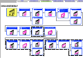
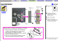
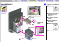
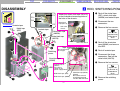
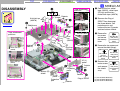
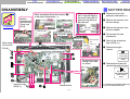
TOP
FOR SAFETY
DISASSEMBLY
FRAME HARNESS
EXPLODED VIEW
PARTS LIST
SERVICE MANUAL
VGC-V Series
American Area
US Model
Canadian Model
Ver. 3-2006C
Revision History
Line up: VGC-V520G
VGC-V517G
VGC-V620G
VGC-V617G
This manual and the constituent data may not be
replicated, copied nor reprinted in whole or in part
without prior written authorization of Sony Corporation.
• Design and specifications are subject to
change without notice.
2006C2700-1
©2006 Sony Corporation
Published by Sony Corporation VBD VAIO Global CS Division
9-876-526-03
PERSONAL COMPUTER
TOP
Information in this document is subject to
change without notice.
Sony, VAIO and CLIE are trademarks or registered trademarks of Sony. Microsoft, Windows,
Windows Media, Outlook, Bookshelf and other
Microsoft products are trademarks or registered
trademarks of Microsoft Corporation in the
United States and other countries. The word
Bluetooth and the Bluetooth logo are trademarks
of Bluetooth SIG, Inc. AMD, the AMD logo, other
AMD product names and combinations thereof
are trademarks of Advanced Micro Devices, Inc.
Intel Inside logo, Pentium, Celeron and Core are
trademarks or registered trademarks of Intel Corporation. Transmeta, the Transmeta logo, Crusoe
Processor, the Crusoe logo and combinations
thereof are trademarks of Transmeta Corporation
in the USA and other countries. Graffiti, HotSync, PalmModem, and Palm OS are registered
trademarks, and the Hotsync logo and Palm are
trademarks of Palm, Inc. or its subsidiaries. (M)
and Motrola are trademarks of Motrora, Inc. Other
Motrola products and services with (R) mark like
Dragomball are the trademarks of Motrola, Inc.
All other names of systems, products and services
in this manual are trademarks or registered trademarks of their respective owners. In this manual,
the (TM) or (R) mark are not specified.
FOR SAFETY
DISASSEMBLY
FRAME HARNESS
EXPLODED VIEW
PARTS LIST
Service and Inspection Precautions
Caution Markings for Lithium/Ion Battery - The
following or similar texts shall be provided on
battery pack of equipment or in both the operating
and the service instructions.
1. Obey precautionary markings and
instructions
Labels and stamps on the cabinet, chassis, and
components identify areas requiring special
precautions. Be sure to observe these precautions,
as well as all precautions listed in the operating
manual and other associated documents.
CAUTION: Danger of explosion if battery is
incorrectly replaced. Replace only with the same
or equivalent type recommended by the
manufacturer. Discard used batteries according
to the manufacturer’s instructions.
2. Use designated parts only
The set’s components possess important safety
characteristics, such as noncombustibility and the
ability to tolerate large voltages. Be sure that
replacement parts possess the same safety
characteristics as the originals. Also remember
that the ! mark, which appears in circuit
diagrams and parts lists, denotes components that
have particularly important safety functions; be
extra sure to use only the designated components.
CAUTION: The battery pack used in this device
may present a fire or chemical burn hazard if
mistreated. Do not disassemble, heat above
100°C (212°F) or incinerate.
Dispose of used battery promptly.
Keep away from children.
CAUTION: Changing the back up battery.
• Overcharging, short circuiting, reverse charging,
multilation or incineration of the cells must be
avoided to prevent one or more of the following
occurrences; release of toxic materials, release
of hydrogen and/or oxygen gas, rise in surface
temperature.
• If a cell has leaked or vented, it should be
replaced immediately while avoiding to touch
it without any protection.
3. Always follow the original design
when mounting parts and routing
wires
The original layout includes various safety
features, such as inclusion of insulating materials
(tubes and tape) and the mounting of parts above
the printer board. In addition, internal wiring has
been routed and clamped so as to keep it away
from hot or high-voltage parts. When mounting
parts or routing wires, therefore, be sure to
duplicate the original layout.
4. Inspect after completing service
After servicing, inspect to make sure that all
–2–
screws, components, and wiring have been
returned to their original condition. Also check
the area around the repair location to ensure that
repair work has caused no damage, and confirm
safety.
5. When replacing chip components...
Never reuse components. Also remember that
the negative side of tantalum capacitors is easily
damaged by heat.
6. When handling flexible print
boards...
• The temperature of the soldering-iron tip should
be about 270°C.
• Do not apply the tip more than three times to
the same pattern.
• Handle patterns with care; never apply force.
Caution: Remember that hard disk drives are
easily damaged by vibration. Always handle
with care.
ATTENTION AU COMPOSANT AYANT
RAPPORT
À LA SÉCURITÉ!
LES COMPOSANTS IDENTIFÉS PAR UNE
MARQUE ! SUR LES DIAGRAMMES
SCHÉMATIQUES ET LA LISTE DES PIÈCES
SONT CRITIQUES POUR LA SÉCURITÉ DE
FONCTIONNEMENT. NE REMPLACER CES
COMPOSANTS QUE PAR DES PIÈSES SONY
DONT LES NUMÉROS SONT DONNÉS DANS
CE MANUEL OU DANS LES SUPPÉMENTS
PUBLIÉS PAR SONY.
TOP
FOR SAFETY
DISASSEMBLY
FRAME HARNESS
EXPLODED VIEW
PARTS LIST
DISASSEMBLY
1
SLIDE COVER ASSY
3
STAND COVER ASSY
4
HDD, SWITCHING
POWER
5
STAND ASSY
6
DVD-1, RIGHT COVER
8
9
2
11 SUB CHASSIS ASSY
13 DC FAN, CPU
12 ENX-30, CNX-266
14 MOTHER BOARD
REAR COVER ASSY,
SWX-184,
RECEIVER (RF)
SHIELD ASSY
10 CNX-263,IFX341,
CNR MODEM
7
MEMORY
15 WIRELESS LAN CARD
DVD-2
16 FRONT SECTION
VGC-V520G/V617G/V620G
17 CNX-264, SWX-174,
RAY-CATCHER
19 LCD SECTION
23
VGC-V520G/V620G
18 CNX-264, SWX-174,
RAY-CATCHER
21 INVERTER UNIT
20 LCD SECTION
22
INVERTER UNIT
24 SPEAKER UNIT
SPEAKER UNIT
VGC-V517G/V617G
–3–
TOP
FOR SAFETY
DISASSEMBLY
DISASSEMBLY
FRAME HARNESS
EXPLODED VIEW
PARTS LIST
1 SLIDE COVER ASSY
1 Move, by sliding, the
slide cover assy upward
until the connectors on the
rear of the set is exposed.
1
Slide cover assy
To Flowchart
2
1
3
2 While pushing the portion
(A), move, by sliding, the
slide cover assy further
upward until the lock is
released.
3 Remove the slide cover
assy on the direction of
the arrow.
A
1
Connectors
–4–
TOP
FOR SAFETY
DISASSEMBLY
FRAME HARNESS
DISASSEMBLY
EXPLODED VIEW
PARTS LIST
2 MEMORY
1 Remove the two screws.
2
Memory cover
Memory (*1)
2
Clip
1
To Flowchart
Ref. No 167
+PS (3 X 6)
4-679-053-01
Silver
2 Disengage the three
detents and remove the
memory cover.
Detents
1
3
3 Open the two clips.
4 Pull out the memory
module (*1) from the board
in the vertical direction.
4
Clip
Notes when installing the Memory module
(1) While the clips are left open, insert the Memory
module so that the protrusion of socket enters
into the notch of the Memory module.
(2) When the Memory module is inserted completely,
check that the clips are closed.
(3) Be sure to insert the Memory modules starting
from the having the smallest bank number.
Memory
Clip
DDR socket
Boss
(1 position) Clip
(*1) Two memory modules are installed
on model V520G and V620G.
–5–
TOP
FOR SAFETY
DISASSEMBLY
FRAME HARNESS
DISASSEMBLY
EXPLODED VIEW
PARTS LIST
3 STAND COVER ASSY
1 Remove the two screws.
3
3
Ref. No 172
FLAT HEAD
4-672-839-11
Black
To Flowchart
2 Disengage. the six detents
and remove the stand
cover assy.
Nickel tape (PS top)
6
3 Turn over the nickel tape
(PS top).
Top shield
4 Peel off the aluminium
tape (75X35).
Aluminium tape
(75X35)
4
5 Remove the two screws.
5
Stand cover assy
Tape attachment positions
2
Ref. No 153
+P 3X3
7-682-144-04
Silver
5 Remove the top shield.
1
Detents
1
–6–
Aluminium tape
(75X35)
TOP
FOR SAFETY
DISASSEMBLY
DISASSEMBLY
FRAME HARNESS
P1
P3
P4
P2
Acetate tape
Nickel tape
(IDE)
1
Attach the nickel cloth tape (50 x 15)
so that it should not cover any portion of
the hole of the chassis.
Acetate tape
Nickel cloth tape
(30X50)
3 Remove the four screws.
Nickel cloth tape (50 x 15)
Nickel cloth tape
(40X70)
6
1
1
1
Hole of the chassis
6
2
1
2
Switching
power.
8
Tape attachment positions
Be careful not to
be caught.
B
B
B
HDD
4
4 Peel off the aluminium
tape (50X95) and remove
the HDD.
6 Disconnect the three
connectors. Peel off the
nickel cloth (40X70).
7 Remove the four screws.
Acetate tape
(Note1)
Fix it at the
center of the
power supply block.
Nickel cloth tape (IDE)
3
Ref. No 166
(SW)(NO.6-32UNC)
4-645-944-22
Silver
5 Peel off acetate tape.
Aluminium tape
(50X95)
A
A
1 Peel off the nickel tape
(IDE), nickel cloth tape
(30X50) and acetate tape.
2 Disconnect the two
connectors.
Nickel cloth
tape (50 x 15)
Hole of the
chassis
5
7
PARTS LIST
4 HDD, SWITCHING POWER
4
To Flowchart
EXPLODED VIEW
Nickel cloth tape (30X50)
A
–7–
Aluminium tape (50X95)
(Note2)
Be careful so that it
should not protrude
into the IDE connector.
Ref. No 165
+K (#6-32UNC 1/4)
2-050-805-01
Black
8 Remove the switching
power.
TOP
DISASSEMBLY
FOR SAFETY
FRAME HARNESS
DISASSEMBLY
EXPLODED VIEW
PARTS LIST
5 STAND ASSY
5
1 Remove the four screws.
1
1
Stand assy
To Flowchart
Ref. No 157
+PS (3 X 8)
2-067-022-01
Black
2 Disengage. the four
detents and the projection
part and remove the stand
assy.
3 Remove the stand cover
(front) in the direction of
the arrow.
2
2
1
Detents
Projection
part
Detents
Stand cover (front)
3
Stand cover
(front)
When assembling,
apply the sankol
(CFD-5010Z).
–8–
TOP
FOR SAFETY
DISASSEMBLY
FRAME HARNESS
DISASSEMBLY
EXPLODED VIEW
PARTS LIST
6 DVD-1, RIGHT COVER
1 Remove the three screws.
6
Ref. No 170
+B (3X4)
2-067-023-01
Black
1
To Flowchart
.
2 Move, by sliding,
the DVD,
optical bracket in the
direction shown by the
arrow, and remove the
DVD, optical bracket
together from the set.
Detents A
Detents
2
A
B
2
Right cover
3
DVD, optical bracket
PC card door
Detents C
–9–
Be careful not to give
physical stress (such as
twisting) or excessive
force when removing the
DVD, optical bracket.
3 Disengage the five
detents (A). While the PC
card door is kept open,
slant the right cover in the
direction of the arrow (B),
and remove five detents
(C)the remove right cover
from the set.
TOP
FOR SAFETY
DISASSEMBLY
FRAME HARNESS
DISASSEMBLY
EXPLODED VIEW
PARTS LIST
7 DVD-2
7
Tape attachment
positions
Nickel tape
(7X11)
To Flowchart
So type
1 Disengage the four
detents and remove the
escutcheon.
Be careflu not to break
the detents
Nickel tape
(7X11)
(Pa Type)
3
Screws
2
3
DVD
Optical bracket
3
5
1
3
(So Type)
Pa type
1 Remove
the two
Ref. No 267
screws,and +P PT 1.7x04
remove the 2-345-480-01
escutcheon.
Black
2 Peel off the two nickel
tape (7X11).
3 Remove the five
screws and remove the
optical bracket.
Ref. No 164
+P (2 X 2)
7-627-853-07
Silver
Detents
Escutcheon (*1)
(*1) Shape of the escutcheon is
different depending on the model.
– 10 –
TOP
FOR SAFETY
DISASSEMBLY
8
DISASSEMBLY
FRAME HARNESS
3
RF
bracket
(*3)
SWX-184 board
Antenna
(RF)
1 Remove the
seven screws.
5
Detents
To Flowchart
4
1
(*2)
Detents
Ref. No 170
+B 3X4
2-067-023-01
Black
2 Disengage the total 20
.
detents. Close
the PC
card door. While the PC
card door is kept closed,
remove the rear cover assy.
3 Remove the
screw and
remove the
RF bracket.
PC card
door
PARTS LIST
8 REAR COVER ASSY, SWX-184, ANNTENA (RF), RECEIVER (RF)
(*1)
Rear cover assy
EXPLODED VIEW
RF
bracket
2
4
3
Receiver
(RF)
Detents
Ref. No 167
+PS (3X6)
4-679-053-01
Silver
4 Disconnect the connector
and disengage the two
detents, then remove the
antenna (RF) (*1) or
receiver (RF) (*2) from the
RF bracket.
5 Remove the
screw and
remove the
SWX-184
board (*3).
Ref. No 167
+PS (3X6)
4-679-053-01
Silver
(*1) V517G/V617G Model only
(*2) V520G/V620G Model only
(*3) V520G/V617G/V620G Model only
– 11 –
TOP
DISASSEMBLY
FOR SAFETY
FRAME HARNESS
EXPLODED VIEW
PARTS LIST
9 SHIELD ASSY
DISASSEMBLY
4
(*1)
9
(*2)
Shield Detents
(hinge)
Nickel cloth tape
(40X70)
To Flowchart
Tape attachment
positions
(*3)
3
5
Shield assy
Memory
cover
1
Tape attachment
positions
Nickel cloth tape
(40X70)
Nickel tape (50X15)
1
Nickel tape
(50X15)
2 Remove the Plug of
SPDIF. Then disengage
the three detents, two
projection parts and
remove the two IO panels
.
and two bottom
shields.
Nickel tape (50X15)
Nickel tape (50X15)
1
1 Peel off the four nickel
tape (50X15), nickel tape
(PS top) and the two
nickel cloth tape (40X70).
Nickel
tape
(50X15)
3 Remove the
two screws
and remove
the memory
cover.
(*3)
5
Nickel tape (50X15)
Nickel tape
(PS top)
4 Remove the two screws and
remove the shield (hinge).
(*1)
(*2)
Ref. No 168
Bottom (L) shield
IO (L)
panel
Nickel cloth tape
(40X70)
2
Projection
part
Projection
parts
Bottom (R)
shield
Nickel tape (PS top)
Ref. No 167
+PS (3 X 6)
4-679-053-01
Silver
2
(M 3X5)
3-081-229-01
Silver
Ref. No 167
+PS (3 X 6)
4-679-053-01
Silver
5 Remove the
twelve screws Ref. No 167
and remove
+PS (3 X 6)
the shield
4-679-053-01
Silver
assy.
Detents
IO (R)
panel
Projection
part
Plug of SPDIF
– 12 –
Detents
(*1) V517G/V520G Model only
(*2) V617G/V620G Model only
(*3) V517G/V617G Model only
TOP
FOR SAFETY
DISASSEMBLY
DISASSEMBLY
10
FRAME HARNESS
EXPLODED VIEW
PARTS LIST
0 CNX-263, IFX-341 CNR MODEM
1 Remove the wire press
clamp and peel off the
aluminium tape (50X70)
Disconnect the three
connector.
Tape attachment positions, routing the cables
Aluminium tape
(50X70)
Cross the cable (1)
To Flowchart
Route the harness (1)
in between the IDE
connector and capacitor.
Wire press clamp
IFX-341 board
Be careful that the harness
should not be located 3 mm
or more away from
the Mother Board.
Ref. No 167
+PS (3 X 6)
4-679-053-01
Silver
3 Remove the screw and
disconnect the connector,
then remove the CNR
modem.
4
2
3
1
2 Remove the
two screws
and remove
the CNX-263
board.
Ref. No 167
+PS (3 X 6)
4-679-053-01
Silver
3
1
4 Remove the two screws and
disconnect the connector,
then remove the IFX-341
board.
3
2
Ref. No 151
+B (2 X 3)
2-108-226-01
Black
3
CNR modem
CNX-263 board Aluminium tape (50X70) Wire press clamp
– 13 –
TOP
FOR SAFETY
DISASSEMBLY
FRAME HARNESS
DISASSEMBLY
11
PC card panel
4
EXPLODED VIEW
PARTS LIST
!¡ SUB CHASSIS ASSY
1 Remove the two screws
and remove the PC card
panel.
1
4
3
Ref. No 167
+PS (3 X 6)
4-679-053-01
Silver
To Flowchart
2
2 Disconnect the connector.
3 Remove the
two screws.
Sub chassis assy
6
5
6
4 Remove the
six screws.
Ref. No 156
+PS (3 X 22)
2-109-403-01
Silver
Ref. No 167
+PS (3 X 6)
4-679-053-01
Silver
5 Lift up the sub chassis
assy and disconnect the
connector.
6 Disconnect the three
connectors.
– 14 –
TOP
DISASSEMBLY
FOR SAFETY
FRAME HARNESS
DISASSEMBLY
EXPLODED VIEW
!™ ENX-30, CNX-266
1 Remove the
four screws.
12
3
Gasket (AY)
To Flowchart
Ref. No 167
+PS (3 X 6)
4-679-053-01
Silver
2 Remove the harness from
.
the notch. Remove,
by
sliding, the ENX-30 board
and CNX-266 board.
ENX-30 board
Support bracket
PARTS LIST
1
3
(*2)
4
1
3 Remove the gasket (AY)
and support bracket.
(*1)
CNX-266 board
Tape attachment positions
2
Gasket (P3X8X61)
Notch
Route the harness through
the notch (2) as shown.
4 Disconnect the connector
and remove the CNX-266
board from the ENX-30
board.
Nickel cloth tape (PCMCIA)
Sub chassis assy
1
Nickel cloth tape (PCMCIA)
– 15 –
(*1) When inserting the ENX-30 board
into the CNX-266 board, repeat
pushing the ENX-30 board twice
to ensure the secure connection.
(*2) Because there is no support for
the CNX-266 board within the
encircled area, never touch this
portion to avoid any damages.
TOP
FOR SAFETY
DISASSEMBLY
FRAME HARNESS
DISASSEMBLY
EXPLODED VIEW
PARTS LIST
!£ DC FAN, CPU
1 Peel off the acetate tape.
13
To replace the CPU or heat sink (in case that CPU is
equipped with heat sink), install new CPU or heat sink
after thermal dissipation grease is wiped off and
apply the grease to the position shown in the figure.
Thermal dissipation grease:
Amount of application:
To Flowchart
Acetate tape
Route the two black harness
through the notch as shown.
∗ Take care not to apply
the grease to any other
places because it has
high conductivity.
Silicon compound (G-765) 90G
0.5 g (equivalent to twice the size
a wooden safety match head)
Grease
(on the entire surface
of heat splitter)
1
3
2
3 Remove the four screws
included in the DC fan.
4 Raise the lever in the
direction of the arrow(A).
5 Pull the CPU straight up
and remove it.
DC fan
CPU
Acetate
tape
2 Disconnect the two
connectors.
A
4
5
Notes on installing the DC fan
During installation, be
careful not to damage
the chips on the Mother
Board as shown in the
illustration.
– 16 –
TOP
FOR SAFETY
DISASSEMBLY
FRAME HARNESS
DISASSEMBLY
14
PARTS LIST
!¢ MOTHER BOARD
When assembling, press
the UL tape with finger in
the way of tracing the UL
tape from one end up to
the other end.
When assembling, Route the harness (1)
in the shown the pictures. (*1)
Bind the
harnesses with
the wire clamp.
(Purse Lock
DIA.8)
To Flowchart
EXPLODED VIEW
UL tape
Ferrite core
1 Remove the two film
antennas and cables (*1).
2 Remove the harness from
the wire clamp.
Ferrite core
MB
side
HDD
UL tape side
3 Remove the harness from
the wire saddle.
Harness clip
4 Disconnect the nine
connectors.
Two guides
Ferrite core
Wire clamp Film antenna (*1)
(Purse lock
DIA.8)
Film antenna (*1)
3
1
Nickel cloth tape
and
Ferrite core
6 Remove the eight
screws.
6
2
Route the harness
through the notch
as shown.
2
3
3
4
7
Ref. No 167
+PS (3 X 6)
4-679-053-01
Silver
7 Remove the screw and
remove the mother board.
Ref. No 162
POSITIONING SCREW
4-678-103-01
Silver
6
5
Aluminium tape
(5X25) (*2)
5 Peel off the aluminium
tape (5X25) (*2).
Wire saddle
6
Mother board
– 17 –
(*1) V520G/V617G/V620G Model only
(*2) V517G/V520G Model only
TOP
FOR SAFETY
DISASSEMBLY
DISASSEMBLY
FRAME HARNESS
EXPLODED VIEW
PARTS LIST
qg WIRELESS LAN CARD (VGC-V520G/V617G/V620G)
15
Wireless LAN card
1 Open the two detents of
the socket gently toward
outside.
Detent
1
2 Raise the W-LAN card.
2
To Flowchart
3 Pull the W-LAN card in
an upward angle.
3
1
Socket
Detent
Wireless LAN
card
Check items on installation
• Check that the detents of the socket are not bent.
• Check that the detents are securely engaged in
the recessed portions on the wireless LAN card.
Detents of the socket
Mother board (B side)
– 18 –
TOP
FOR SAFETY
DISASSEMBLY
FRAME HARNESS
DISASSEMBLY
EXPLODED VIEW
PARTS LIST
!§ FRONT SECTION
16
1 Disengage the two detents
and remove the center
cover.
(*4)
3 (*1)
2 Remove the cable from
the wire saddle.
To Flowchart
Wire saddle
2
Front section (*3)
3
(*1)
Center cover
Projected part
3 Remove the screws (*1)
and disengage the detents (*2).
Remove the LCD section.
Ref. No 154
TAPPING P+3
2-067-021-01
Silver
1
Detents
3
3
(*5)
Detents (*2)
(*5)
– 19 –
(*1) Number of screws is different
depending on the model.
V520G/V620G : 14 screws
V517G/V617G : 12 screws
(*2) Number of detents is different
depending on the model.
V520G/V620G : 14 detents
V517G/V617G : 6 detents
(*3) Shape of the front section is
different depending on the model.
(*4) V520G/V620G Model only
(*5) V517G/V617G Model only
TOP
DISASSEMBLY
17
DISASSEMBLY
FOR SAFETY
FRAME HARNESS
EXPLODED VIEW
PARTS LIST
!¶ CNX-264, SWX-174, RAY-CATCHER (VGC-V520G/V620G)
Tape attachment
positions
To Flowchart
Route the flexible
board as shown.
Secure the flexible board
with the two UL tapes.
1
1 Peel off the aluminium
tape (60X25) and
disconnect the connector, and
remove the three screws.
Then remove the MSBD
bracket and the CNX-264 board.
Ref. No 167
+PS (3 X 6)
4-679-053-01
Silver
Aluminium tape
(60X25)
Aluminium tape
MSBD bracket (60X25)
CNX-264 board
2 Disconnect the connector
and remove the two
screws, and remove the
SWX-174 board.
1
1
Ref. No 167
+PS (3 X 6)
4-679-053-01
Silver
3
3 Disconnect the connector
and remove the screw,
then remove the Raycatcher.
1
2
Ref. No 167
+PS (3 X 6)
4-679-053-01
Silver
2
SWX-174 board
2
3
Ray-catcher
3
– 20 –
TOP
FOR SAFETY
DISASSEMBLY
18
DISASSEMBLY
FRAME HARNESS
1 Peel off the aluminum
tape (60X25) and
disconnect the connector,and
remove the three screws.
Then remove the MSBD
bracket and the CNX-264
board.
Route the two flexible
board through the
notch as shown.
Secure the flexible board
with the two UL tape.
To Flowchart
Ref. No 167
+PS (3 X 6)
4-679-053-01
Silver
Aluminum tape
(60X25)
3
1
2
2 Disconnect the connector
and remove the two
screws, and remove the
SW holder and the
SWX-174 board.
Ref. No 167
+PS (3 X 6)
4-679-053-01
Silver
2
1
PARTS LIST
!• CNX-264, SWX-174, RAY-CATCHER (VGC-V517G/V617G)
Tape attachment
positions
Aluminum tape
(60X25)
SWX-174
board
EXPLODED VIEW
2
3 Disconnect the connector
and remove the screw,
then remove the Raycatcher unit.
SW holder
MSBD bracket
3
CNX-264 board
– 21 –
Ray-catcher unit
Ref. No 167
+PS (3 X 6)
4-679-053-01
Silver
TOP
FOR SAFETY
DISASSEMBLY
DISASSEMBLY
FRAME HARNESS
EXPLODED VIEW
PARTS LIST
!ª LCD SECTION (VGC-V520G/V620G)
19
1 Remove the two screws.
Ref. No 163
POSITIONING SCREW M4
2-067-017-01
Silver
To Flowchart
LCD section
2
1
2 Remove the. two screws.
Route the two flexible boards (3) through
the hole of the chassis as shown.
3
3
3
– 22 –
Ref. No 158
+PS (4X6)
2-067-018-01
Silver
3 While removing the two
harnesses through the hole
of the chassis, remove the
LCD section.
TOP
FOR SAFETY
DISASSEMBLY
DISASSEMBLY
FRAME HARNESS
EXPLODED VIEW
PARTS LIST
@º LCD SECTION (VGC-V517G/V617G)
20
1 Peel off the aluminium tape
(50X105).
2
2 Remove the six screws.
To Flowchart
LCD section
Ref. No 167
+PS (3 X 6)
4-679-053-01
Silver
2
3 While removing the two
harnesses through the hole
of the chassis, remove the
LCD section.
1
3
3
3
Route the two flexible boards (3) through
the hole of the chassis as shown.
Aluminium tape
(50X105)
– 23 –
TOP
FOR SAFETY
DISASSEMBLY
DISASSEMBLY
FRAME HARNESS
PARTS LIST
@¡ INVERTER UNIT (VGC-V520G/V620G)
21
UL tape
1 Remove the three screws
and remove the shield
(inverter).
Shield (inverter)
Shield
4
1
Ref. No 167
+PS (3 X 6)
4-679-053-01
Silver
3
To Flowchart
2 Remove the two screws,
disconnect the eight
connectors and remove
the inverter unit.
Secure the cable with the
UL tape (3).
Copper leaf tape
2
UL tape
EXPLODED VIEW
2
Ref. No 167
+PS (3 X 6)
4-679-053-01
Silver
3 Peel off the UL tape.
5
4 Remove the four screws
and remove the shield.
2
Inverter unit
(10 lamps)
LCD section
– 24 –
Ref. No 167
+PS (3 X 6)
4-679-053-01
Silver
5 Peel off the copper leaf
tape and disconnect the
connector.
TOP
FOR SAFETY
DISASSEMBLY
DISASSEMBLY
EXPLODED VIEW
PARTS LIST
@™ INVERTER UNIT (VGC-V517G/V617G)
1 Remove the two screws
and the remove the LCD
bracket (L).
22
To Flowchart
FRAME HARNESS
LCD bracket (R)
4
Ref. No 167
+PS (3 X 6)
4-679-053-01
Silver
LCD bracket (L)
4
1
Copper leaf tape (*1)
Nickel tape (50x15) (*2)
2 Remove the two screws,
disconnect the four connectors
and remove the inverter unit,
LCD bracket (R).
UL tape (*2)
2
Ref. No 167
+PS (3 X 6)
4-679-053-01
Silver
5
Inverter unit
(4 lamps)
3
3 Remove the
three screws
Ref. No 167
and remove the +PS (3 X 6)
inverter unit
4-679-053-01
Silver
from the LCD
bracket (R).
2
4 Disconnect the four
connectors.
LCD section
5 Peel off the copper leaf
tape (*1) or nickel tape
(50x15), UL tape (*2) and
disconnect the connector.
2
(*1) V517G Model only
(*2) V617G Model only
– 25 –
TOP
DISASSEMBLY
FOR SAFETY
DISASSEMBLY
FRAME HARNESS
PARTS LIST
@£ SPEAKER UNIT (VGC-V520G/V620G)
23
Fix the harness at the two positions as
shown using the nickel cloth tape (IDE)
(15 x 40) and the two harness clips.
Then route the harness through the
hole of the chassis.
To Flowchart
Harness clips
Position: 5 mm away from the opening
of the fan.
Install it so that about one third of
the LCD stopper protrudes from
the LCD fan housing.
Ref. No 167
+PS (3 X 6)
4-679-053-01
Silver
3
1
LCD stopper
LCD
fan housing
1
3
Notes on installing the speaker unit
2
1 Peel off the nickel cloth
tape (15X40) from the
harness of the speaker unit
and remove it from the two
harness clip.
2 Remove the four screws
and remove the speaker
unit.
Nickel cloth tape
(15X40)
Notes on installing the LCD stopper
• Check that any part of the speaker
does not ride over the harness.
• Push the harness against the speaker
after installing the speaker.
EXPLODED VIEW
2
Speaker unit
– 26 –
TOP
DISASSEMBLY
FOR SAFETY
DISASSEMBLY
FRAME HARNESS
PARTS LIST
@¢ SPEAKER UNIT (VGC-V517G/V617G)
24
Fix the harness at the two positions as
shown using the nickel cloth tape (IDE)
(15 x 40) and the two harness clips.
Then route the harness through the
hole of the chassis.
To Flowchart
EXPLODED VIEW
1 Disconnect the three
connectors.
2 Remove the screw and
two detent remove the
Main board (RF).
Nickel cloth tape
(15X40)
Ref. No 167
+PS (3 X 6)
4-679-053-01
Silver
Harness clips
Main baord (RF)
3 Peel off the nickel cloth
tape (15X40) from the
harness of the speaker unit
and remove it from the two
harness clip.
1
3
2
3
Ref. No 167
+PS (3 X 6)
4-679-053-01
Silver
Detent
4
2
Speaker unit
4 Remove the four screws
and remove the speaker
unit.
4
– 27 –
TOP
FOR SAFETY
FRAME HARNESS
DISASSEMBLY
EXPLODED VIEW
PARTS LIST
3
2
1
SWX-174
BOARD
MS HARNES
MS264
IFX-341
BOARD
USB5 USB3
CN5
FLT-5
BOARD
MEMORY
STICK
SLOT
USB
CONNECT
FFC
(OPTICAL
IFX-341)
AUDIO
HARNES
CON2
CON4
USB
CON3
CN8
CN4CN3
IEEE1 J2 J1
i.LINK
PC CARD
SLOT
USB1 USB2
CNX-266
BOARD
SW1
PC11
CN11
MIC IN
CON1
HEAD
PHONE
POWER
SWITCH
i LINK/USB
HARNES
CNX-263
BOARD
SWX-184 BOARD
IO (R) PANEL
i.LINK
CN1
CON1
USB USB NETWORK
From board to connector (direct connection)
Harness (with connectors on both ends)
Harness (soldering on either end)
CNX-264
BOARD
RF SWITCH HARNES
(VGC-V517G/V617G)
MODEM1
ZR4
LCD
FAN1
ROM
SPDIF1 CN1
JP1
DC FAN
(LCD)
(VGC-V520G/
V617G/
V620G)
CNR
MODEM
FB901
IO (L)
PANEL
(VGC-V517G/V617G)
ANTENNA CABLE (RF)
MODEM OPTICAL LINE IN
OUT
(VGC-V520G/V620G)
USB (IR)
HARNES
(VGC-V520G/V617G/V620G)
VHF/UHF S VIDEO AUDIO
ANTENNA IN
IN
LAN1
IEEE1
DVD-RW
Drive
RIGHT SIDE
CN1
MIC263
IDE1
PWCON1
HARNES (USB RF)
HARNES IFX-334
CN100
CN9
IDE2
CHA CPU CPU
FAN1 FAN2 FAN1
CN350 CN150
CN14
(VGC-V520G/
V620G)
CMOSCLEAR
SWX-174
IFX-334 BOARD
ENX-30 BOARD
P4
CAUTION
RF SWITCH
HARNES
J4
MAIN BOARD (RF)
CN1
CN1
CN2
J7
RAYCATCHER RECEIVER (RF) ANTTENA (RF)
(VGC-V520G/V620G)
UNIT
Don't touch the jumper switches while the main power is turned on.
Be sure to turn off the power switch and disconnect the AC power cord from the wall outlet.
– 28 –
J1
XMM2
SWX-U1
FFC (LED/SWITCH SWX-174)
ILINK263
HARNES (YU AUDIO)
CPU
AUX1
MEMORY MODULE
FILM
ANTENNA Black
C1
HDD
PCI1
CN1
CN5
CN4
LCD
HARNES
Gray
SPK-R1 SPK-L1
MEMORY MODULE
(VGC-V520G/V620G)
MOTHER BOARD
INV CON1
LVDS1
POWER IDE
(VGC-V520G/V617G/V620G)
FILM
ANTENNA
HARNES (IDE HDD)
WHITE
RED
WIRELESS
LAN CARD
Main
Aux
INVERTER
UNIT
P1
12V RELAY HARNES
P2
INVERTER
UNIT (VGC-V517G/V617G)
WHITE
RED
JP7
CN2
CN6 CN3
AC INPUT
100V-120V
3A
LCD
UNIT
DC FAN (CHASSIS) DC FAN (WITH HEAT SINK)
SPEAKER UNIT
R
L
P3
USB (IR) HARNES
CN4
CN6
CN1
CN2
CN8
CN7
LCD
UNIT
SWITCHING
POWER
XMM1
P4
LCD HARNES
CN5
CN3
12V INVERTER HARNES
FRAMEHARNESS
• Mother Board jumper setting.
When the mother board is replaced by the repair mother
board,set the jumper switches to the default set up as
shown below.
COMSCLEAR
1-2
Clear
2-3
Normal
Default
TOP
FOR SAFETY
DISASSEMBLY
EXPLODED VIEW
EXPLODED VIEW
FRAME HARNESS
PARTS LIST
1 REAR UNIT (VGC-V520G/V620G)
Main unit
125
88
229
98
214
92
167
91
95
177
167
81
99
A
115
178
96
97
126
124
167
207
B
192
207
204 206
231
240
238
185
207
206
186
82
167
(V520G)
168
B
213
78
170
167
(V620G)
188
94
207
40
(NOTE1)
C
94
113
174
94
94
85
93
165
114
173
52
157
211
157 166
236
129
178
119
209
234
80
265
130
122
264
172
11
100
153
A
257
86
C
– 29 –
172
221
268
(NOTE1) : Refer to page 39.
TOP
FOR SAFETY
DISASSEMBLY
EXPLODED VIEW
EXPLODED VIEW
FRAME HARNESS
PARTS LIST
2 REAR UNIT (VGC-V517G/V617G)
Main unit
125
88
229
98
214
92
167
91
95
177
167
81
99
A
115
178
96
97
126
124
167
207
B
192
207
204 206
213
231
240
B
167
(V517G)
168
238
185
207
207
186
206
82
78
170
167
(V617G)
188
94
207
40
(NOTE1)
C
94
113
80
174
94
94
85
93
165
114
173
52
157
211
157 166
236
129
178
119
209
234
130
265
172
11
122
264
(V617G) (V617G)
100
153
A
257
C
172
221
– 30 –
86
268
(NOTE1) : Refer to page 39.
TOP
FOR SAFETY
DISASSEMBLY
EXPLODED VIEW
266
EXPLODED VIEW
FRAME HARNESS
PARTS LIST
3 MAIN UNIT (VGC-V520G/V620G)
Front unit
263
(Pa Type)
263
260
260
1
(NOTE2)
266
207
263
256
22
2
5
42
48
D
266
3
72
263
260
259
262
C1
(So Type)
194
267
4
263
266
25
176
21
262
260
D
162
54 44
A
45
51
49
167
262
126
266
260
262
B
53
77
C
31
250
226
52
24
167
167 101
164
167
76
90
156
46
(V520G)
48
269
(NOTE2)
23
37
34
A
151
35
208
C
D
167 222
164
B
47
167
53
43
32
54
227
187
210
189
179
167
167
167
(NOTE2) : Refer to page 39.
– 31 –
TOP
FOR SAFETY
DISASSEMBLY
EXPLODED VIEW
FRAME HARNESS
EXPLODED VIEW
PARTS LIST
4 MAIN UNIT (VGC-V517G/V617G)
263
266
(Pa Type)
(V617G)
(V617G)
263
260
260
266
48
207
263
72 256
266
Front unit
5
(So Type)
C1
267
4
21
D
262
226
44
266
260
25
176
263
262
D
42
3
263
260
259
(V617G)
22
2
1
(NOTE2)
54
31
250
49
162
167
53
51
B
45
52
24
164
167
A
262
126
(V617G)
266
260
262
(V617G)
C
77
(V617G)
167 101
167
76
269 (V517G)
(NOTE2)
23
90
156
46
164
37
48
35
A
151
34
D
167 222
208
C
B
47
50
167
43
32
54
227
187
– 32 –
210
179
189
167
167
167
(NOTE2) : Refer to page 39.
TOP
FOR SAFETY
DISASSEMBLY
EXPLODED VIEW
EXPLODED VIEW
FRAME HARNESS
PARTS LIST
5 FRONT UNIT (VGC-V520G/V620G)
218
167
87
167
126
181
73
197
71
41
167
126
167
163
194
77
167
126
72
89
244
194
154
271
158
203
48
(NOTE3)
205
212
270
228
126
212
51
228
167
167
200
183
112
38
74
167
191
232
44
126
167
230
53
49
193
33
167
108
193
– 33 –
191
49
102
167 258
75
109
190
167
(NOTE3) : Refer to page 40.
TOP
FOR SAFETY
DISASSEMBLY
EXPLODED VIEW
FRAME HARNESS
EXPLODED VIEW
PARTS LIST
6 FRONT UNIT (VGC-V517G/V617G)
(V617G)
87
77
198
110 167
167
167
71
53
51
89
167
BA
154
177
41
74
39
50
274 (V617G)
A
167
55
271 (V517G)
73
228
167
111
207
126
48
(NOTE3)
203
212
(V617G)
228
193
B
C
167
191
C
175
38
183
192
109
230
44
167
126
232
167
55
75
191 190
49
167
72
33
167
102
108
49
167 258
167
(V617G)
– 34 –
235
(NOTE3) : Refer to page 40.
TOP
FOR SAFETY
DISASSEMBLY
EXPLODED VIEW
FRAME HARNESS
EXPLODED VIEW
PARTS LIST
7 ACCESSORIES
301
KEY BOARD
304
REMOTE COMMANDER
(RM-VC10U)
308
CONNECTION CORD (RK-G129)
312
310
311
302
AC CORD
309
VIDEO ADAPTER CABLE
307
CONNECTION CORD (F TYPE RF)
303
MOUSE
– 35 –
TOP
FOR SAFETY
DISASSEMBLY
PARTS LIST
EXPLODED VIEW
PARTS LIST
Basic List
NOTE :
• The parts listed here are for service, and therefore they may be
different from the parts shown in circuit diagrams or used in the set.
• # Parts/components that are available in the commercial market.
• The number of the mark “2” is the quantity at the time of preinstallment.
Basic List
• The parts in the “Basic List” will be refer red to as the part list.
The part order should be taken place based on the part number
in the list.
Substitution List
• If the repair part in the “Basic List” was not available, refer to order the
“Substitution List” if available.
The components identified by
mark ! or dotted line with mark
! are critical for safety.
Replace only with part number
specified.
FRAME HARNESS
Les composants identifiés par
une marque ! sont critiques
pour la sécurité.
Ne les remplacer que par une
pièce portant le numéro spécifié.
– 36 –
2005 Spring 2005 Summer
Ref No
Part No
Description
V520G V517G V620G V617G Note
1
1-789-042-24
MOTHER BOARD (DI/H)
Note2:Refer to page 39.
---------------------------------------------------------------------------------------------------------------------------------------------------------------------------------------1-789-042-42
MOTHER BOARD (DI/H)
Note2:Refer to page 39.
2
A-1088-786-A
CPU(P4/3EG/7PM)ASSY(S)
6-707-380-01
---------------------------------------------------------------------------------------------------------------------------------------------------------------------------------------A-1089-602-A
CPU(P4/3.20EG/7PN) ASSY (S)
6-707-379-01
---------------------------------------------------------------------------------------------------------------------------------------------------------------------------------------A-1090-822-A
CPU(P4/3.40EG/7PP)ASSY (S)
6-707-378-01
3
1-787-165-23
FAN, DC (WITH HEATSINK)
4
6-600-388-01
DDR400 512MB(HYS64D64320HU-5-C)
2
2
5
7-300-000-40
SILICON COMPOUND (G-765) 90G
11
A-1085-340-A
HDD (W-CVXL80-2/WD2500BB-98GUA0/250GB)ASSY(S)
---------------------------------------------------------------------------------------------------------------------------------------------------------------------------------------A-1085-341-A
HDD (W-CVXL80-2/WD2000BB-98GUA0/200GB)ASSY(S)
---------------------------------------------------------------------------------------------------------------------------------------------------------------------------------------A-1126-699-A
HDD (W-CVXL80-2/WD2500BB-98GUC0/250GB) ASSY (S)
---------------------------------------------------------------------------------------------------------------------------------------------------------------------------------------A-1126-695-A
HDD (W-CVXL80-2/WD2000BB-98GUC0/200GB) ASSY (S)
21
8-457-624-90
DRIVE, DVD DW-D56A-V2
---------------------------------------------------------------------------------------------------------------------------------------------------------------------------------------8-457-664-10
DRIVE, DVD DW-D56A-V3
22
1-797-051-21
W-DVD (DVR-K14VA)
23
2-022-225-01
BRACKET, OPTICAL
24
X-2023-819-3
ESCUTCHEON ASSY
---------------------------------------------------------------------------------------------------------------------------------------------------------------------------------------X-2023-819-4
ESCUTCHEON ASSY
25
X-2023-820-2
ESCUTCHEON (PIONEER) ASSY
! 31
1-761-824-32
CNR MODEM (GVC R5A W/COVER)
32
1-761-927-12
CNX-263 BOARD
33
1-761-928-11
CNX-264 BOARD
34
1-761-929-11
CNX-266 BOARD
---------------------------------------------------------------------------------------------------------------------------------------------------------------------------------------1-761-929-12
CNX-266 BOARD
35
A-1095-407-A
ENX-30 (MC2 US) ASSY
---------------------------------------------------------------------------------------------------------------------------------------------------------------------------------------A-1095-408-A
ENX-30 (VC2 US) ASSY
---------------------------------------------------------------------------------------------------------------------------------------------------------------------------------------A-1119-190-A
ENX-30 (VCA_US) ASSY
37
1-761-931-11
IFX-341 BOARD
38
1-761-932-11
SWX-174 BOARD
39
1-761-852-21
BOARD, MAIN (RF)
---------------------------------------------------------------------------------------------------------------------------------------------------------------------------------------1-761-852-22
BOARD, MAIN (RF)
40
1-468-853-13
POWER, SWITCHING
Note1:Refer to page 39.
---------------------------------------------------------------------------------------------------------------------------------------------------------------------------------------1-468-900-11
POWER, SWITCHING
Note1:Refer to page 39.
41
1-962-816-11
12V INVERTER HARNESS
---------------------------------------------------------------------------------------------------------------------------------------------------------------------------------------1-962-816-21
12V INVERTER HARNESS
42
1-962-815-11
12V RELAY HARNESS
43
1-962-813-11
AUDIO HARNESS
44
1-829-201-12
FFC (LED/SWITCH SWX-174)
45
1-829-202-12
FFC (OPTICAL IFX-341)
46
1-962-811-11
HARNESS (IFX-334)
47
1-962-812-11
I.LINK/USB HARNESS
48
1-962-809-13
LCD HARNESS (HITACHI)
Note3:Refer to page 40.
---------------------------------------------------------------------------------------------------------------------------------------------------------------------------------------1-962-810-13
LCD HARNESS (SAMSUNG)
Note3:Refer to page 40.
---------------------------------------------------------------------------------------------------------------------------------------------------------------------------------------1-962-809-14
LCD HARNESS (HITACHI)
Note3:Refer to page 40.
---------------------------------------------------------------------------------------------------------------------------------------------------------------------------------------1-963-810-12
LCD HARNESS (AUO)
Note3:Refer to page 40.
49
1-962-814-21
MS HARNESS
---------------------------------------------------------------------------------------------------------------------------------------------------------------------------------------1-962-814-31
MS HARNESS
50
1-962-819-11
RF SWITCH HARNESS
51
1-962-817-11
USB (IR) HARNESS
52
1-961-644-63
HARNESS (IDE HDD)
53
1-962-614-22
HARNESS (USB RF)
---------------------------------------------------------------------------------------------------------------------------------------------------------------------------------------1-962-614-11
HARNESS (USB RF)
54
1-960-620-71
HARNESS (YU AUDIO)
55
1-828-103-21
CABLE, ANTENNA (RF)
71
A-1085-217-A
LCD UNIT (HI/20/WXGA) (S)
---------------------------------------------------------------------------------------------------------------------------------------------------------------------------------------A-1070-136-A
LCD UNIT (SA/17/WXGA)ASSY(S)
---------------------------------------------------------------------------------------------------------------------------------------------------------------------------------------A-1085-217-B
LCD UNIT (HI/20/WXGA) (S)
---------------------------------------------------------------------------------------------------------------------------------------------------------------------------------------A-1126-706-A
LCD(AU/17/WXGA) ASSY (S)
72
1-478-702-11
SPEAKER UNIT
! 73
1-478-704-13
INVERTER UNIT (10LAMPS)
---------------------------------------------------------------------------------------------------------------------------------------------------------------------------------------1-478-705-13
INVERTER UNIT (4LAMPS)
---------------------------------------------------------------------------------------------------------------------------------------------------------------------------------------1-478-704-14
INVERTER UNIT (10LAMPS)
---------------------------------------------------------------------------------------------------------------------------------------------------------------------------------------1-479-325-11
INVERTER UNIT (4LAMPS)
TOP
FOR SAFETY
DISASSEMBLY
2005 Spring 2005 Summer
Ref No
Part No
Description
V520G V517G V620G V617G Note
74
1-478-726-21
RAY-CATCHER UNIT
75
1-478-907-22
RECEIVER (RF)
---------------------------------------------------------------------------------------------------------------------------------------------------------------------------------------1-754-304-21
ANTENNA (RF)
---------------------------------------------------------------------------------------------------------------------------------------------------------------------------------------1-754-304-22
ANTENNA (RF)
76
1-787-163-12
DC FAN (CHASSIS)
---------------------------------------------------------------------------------------------------------------------------------------------------------------------------------------1-787-163-13
DC FAN (CHASSIS)
77
1-787-164-11
DC FAN (LCD)
---------------------------------------------------------------------------------------------------------------------------------------------------------------------------------------1-787-164-12
DC FAN (LCD)
78
2-022-229-01
COVER, MEMORY
80
2-022-264-02
COVER, RIGHT
---------------------------------------------------------------------------------------------------------------------------------------------------------------------------------------2-022-264-11
COVER, RIGHT
81
2-022-286-01
COVER (20), CENTER
---------------------------------------------------------------------------------------------------------------------------------------------------------------------------------------2-022-325-01
COVER (17), CENTER
82
2-022-260-03
COVER (20), REAR
---------------------------------------------------------------------------------------------------------------------------------------------------------------------------------------2-022-324-03
COVER (17), REAR
85
2-022-307-02
COVER (FRONT), STAND
86
X-2021-203-2
COVER ASSY, STAND
87
A-1082-363-A
COVER20 ASSY (METALLIC), FRONT
---------------------------------------------------------------------------------------------------------------------------------------------------------------------------------------A-1082-364-D
COVER 17 ASSY (CLEAR), FRONT
88
X-2021-149-3
COVER ASSY, SLIDE
89
X-2021-144-2
MAIN CHASSIS (20) ASSY
---------------------------------------------------------------------------------------------------------------------------------------------------------------------------------------X-2021-154-3
MAIN CHASSIS (17) ASSY
---------------------------------------------------------------------------------------------------------------------------------------------------------------------------------------X-2055-742-1
MAIN CHASSIS(17) ASSY
90
X-2021-145-2
CHASSIS ASSY, SUB
91
X-2021-146-2
SHIELD ASSY
92
X-2021-147-1
HINJI ASSY
93
X-2021-151-4
PS METAL ASSY
# 94
X-2022-074-1
FOOT ASSY
95
2-022-287-01
PANEL, IO (L)
96
2-022-288-01
PANEL, IO (R)
97
2-022-289-01
PANEL, PC CARD (20)
---------------------------------------------------------------------------------------------------------------------------------------------------------------------------------------2-022-326-01
PANEL, PC CARD (17)
98
2-022-230-01
SHIELD (L), BOTTOM
99
2-022-231-02
SHIELD (R), BOTTOM
100
2-022-311-01
SHIELD, TOP
101
2-022-226-01
BRACKET, SUPPORT
102
2-189-318-02
BRACKET (W-LAN)
108
2-022-232-02
MSBD BRACKET
109
2-189-319-01
BRACKET (2.4G), RF
---------------------------------------------------------------------------------------------------------------------------------------------------------------------------------------2-159-429-02
RF BRACKET
110
2-022-317-01
LCD BRACKET (L)
---------------------------------------------------------------------------------------------------------------------------------------------------------------------------------------2-594-822-01
LCD BRACKET (L) (A)
111
2-022-318-02
BRACKET (R), LCD
---------------------------------------------------------------------------------------------------------------------------------------------------------------------------------------2-594-823-01
LCD BRACKET (R) (A)
112
2-025-555-01
SWBD BRACKET (20)
113
2-022-261-02
POWER BUTTON (20)
---------------------------------------------------------------------------------------------------------------------------------------------------------------------------------------2-149-287-01
POWER BOTTON (17)
114
2-022-265-01
DOOR, CONNECTOR
115
A-1092-884-A
ROTATION ASSY (T1.5) (S)
119
2-022-668-01
DOOR (20), PC CARD
---------------------------------------------------------------------------------------------------------------------------------------------------------------------------------------2-022-669-01
DOOR (17), PC CARD
122
2-148-383-01
COVER, SPACE
124
4-649-870-11
LABEL (ETHER), CAUTION
125
2-580-090-01
ID LABEL
---------------------------------------------------------------------------------------------------------------------------------------------------------------------------------------2-580-091-01
ID LABEL
--------------------------------------------------------------------------------------------------------------------------------------------------------------------------------------2-599-552-01
LABEL, ID
---------------------------------------------------------------------------------------------------------------------------------------------------------------------------------------2-599-553-01
LABEL, ID
126
4-676-734-01
TAPE, UL
129
2-189-120-02
LABEL (L), I/O
130
2-189-121-02
LABEL (AY), I/O
151
2-108-226-01
+B2X3
153
7-682-144-04
SCREW +P 3X3
154
2-067-021-01
TAPPING +P3
---------------------------------------------------------------------------------------------------------------------------------------------------------------------------------------2-067-021-11
TAPPING +P3
156
2-109-403-01
+PS3X22
157
2-067-022-01
+PS3X8
158
2-067-018-01
+PS4X6
162
4-678-103-01
POSITIONING SCREW
163
2-067-017-01
SCREW (M4), POSITIONING
FRAME HARNESS
EXPLODED VIEW
PARTS LIST
2005 Spring 2005 Summer
Ref No
Part No
Description
V520G V517G V620G V617G Note
164
7-627-853-07
PRECISION SCREW +P 2X2 TYPE 3
---------------------------------------------------------------------------------------------------------------------------------------------------------------------------------------7-627-553-17
PRECISION SCREW +P 2X2 TYPE 3
165
2-050-805-01
SCREW (+K) (#6-32UNC 1/4)
166
4-645-944-22
SCREW (SW) (NO.6-32UNC)
167
4-679-053-01
SCREW,+PS3X6
168
3-081-229-01
SCREW (M3X5)
170
2-067-023-01
+B3X4
172
4-672-839-11
HEAD, M3 FLAT
173
X-2022-907-1
SHIELD ASSY, PS
174
2-159-536-01
TAPE, PS SHIELD
175
2-149-100-03
SW HOLDER (17)
176
2-159-619-01
TAPE, ACETATE
177
2-176-668-01
TAPE, ACETATE
178
2-177-837-01
TAPE, ACETATE
179
2-177-104-01
TAPE (50X70), ALUMINUM
181
2-055-987-01
INSULATER (INVERTER 20)
183
2-514-965-01
GASKET (2.5X5X10)
185
2-177-101-01
GASKET (2X7X130)
186
2-177-106-01
GASKET (7X10X80)
187
2-177-100-01
GASKET (AYAME)
188
2-159-545-01
GASKET (L10X10X25)
189
2-176-587-01
GASKET (P3X8X61)
190
2-159-542-01
GASKET (PCMCIA 7X10X65)
191
2-177-169-01
CUSHION (T0.5 5X170)
192
2-159-962-01
CUSHION (T2 10X10)
193
2-177-170-02
CUSHION (T2 30X40)
194
2-148-121-01
TAPE, CONNECTOR
197
2-148-374-02
SHIELD (INVERTER 20)
198
2-636-864-01
PLATE (LCD FAN)
200
2-177-410-01
SPACER (T0.8 8X70)
203
2-177-107-01
TAPE (15X40), NICKEL CLOTH
204
2-177-108-01
TAPE (30X50), NICKEL CLOTH
205
2-515-166-01
TAPE (340X30), ALUMINUM
206
2-177-102-01
TAPE (40X70), NICKEL CLOTH
207
2-176-599-01
TAPE (50X15), NICKEL
208
2-177-160-01
TAPE (7X11), NICKEL
209
2-177-684-11
TAPE (IDE), NICKEL
210
2-176-588-01
TAPE (PCMCIA), NICKEL CLOTH
211
2-159-547-01
TAPE (PS TOP), NICKEL
212
4-999-506-01
CLIP, HARNESS
213
2-159-964-01
NON WOVEN CLOTH (MEMORY COVER)
214
2-159-444-01
SADDLE, WIRE
218
2-148-375-01
SHIELD (LCD-BD 20)
221
2-178-263-01
CLAMP, AC
222
2-186-828-01
SPACER (CONVEX)
226
9-885-068-36
PLUG OF SPDIF (FOR SERVICE)
227
2-345-120-01
CLAMP, WIRE PRESS
228
2-318-604-01
SHEET (15X15), HEAT CONDUCTION
229
2-318-852-01
DUCT
230
2-320-037-01
NON WOVEN CLOTH (MS BRACKET)
231
2-349-336-01
SHIELD (HINGE)
232
2-514-266-01
TAPE (60X25), ALUMINUM
234
2-514-269-02
TAPE (50X95), ALUMINUM
235
2-514-270-01
TAPE (50X105), ALUMINUM
236
2-514-275-01
TAPE (75X35), ALUMINUM
238
2-541-638-01
GASKET (PS,8X10X165)
240
2-349-841-01
GASKET (3X10X30)
244
2-541-630-01
STOPPER, LCD
250
2-514-990-02
TAPE (MODEM), NICKEL
256
2-056-666-02
CLAMP (PURSE LOCK DIA. 8)
257
2-547-981-01
TAPE (14X25), ALUMINUM
258
1-789-043-11
SWX-184 BOARD
259
1-789-014-11
CARD,WIRELESS LAN
260
1-400-255-21
FERRITE CORE
262
1-754-354-11
ANTENNA, FILM
263
1-754-354-21
ANTENNA, FILM
264
2-189-316-01
SWITCH (W-LAN), SLIDE
265
2-189-317-02
LENS (W-LAN), LED
266
2-349-828-01
TAPE, CORE
– 37 –
TOP
FOR SAFETY
DISASSEMBLY
2005 Spring
2005 Summer
Ref No
Part No
Description
V520G V517G V620G V617G Note
267
2-345-480-01
+P PT 1.7X04 CM3
268 ---------------------------------------------------------------------------------------------------------------------------------------------------------------------------------------2-580-080-01
LABEL, MODEL NUMBER
2-580-081-01
LABEL,
MODEL
NUMBER
---------------------------------------------------------------------------------------------------------------------------------------------------------------------------------------2-599-567-01
LABEL, MODEL NUMBER
---------------------------------------------------------------------------------------------------------------------------------------------------------------------------------------2-599-568-01
LABEL, MODEL NUMBER
269
2-588-002-01
TAPE (5X25), ALMINUM
270
2-592-307-01
CUSHION(LVDS)
271
4-663-105-11
TAPE, COPPER LEAF
274
2-176-668-11
TAPE, ACETATE
C1
1-528-174-31
BATTERY, LITHIUM (CR2032)
FRAME HARNESS
EXPLODED VIEW
PARTS LIST
Accessories & Packing Materials List
2005 Spring
2005 Summer
Ref No
Part No
Description
V520G V517G V620G V617G Note
# 301 1-478-887-13
KEY BOARD (US)
---------------------------------------------------------------------------------------------------------------------------------------------------------------------------------------1-479-160-11
KEY BOARD
---------------------------------------------------------------------------------------------------------------------------------------------------------------------------------------1-478-887-21
KEY BOARD (US)
!# 302 1-827-924-11
CORD, AC
# 303 1-797-022-31
MOUSE
---------------------------------------------------------------------------------------------------------------------------------------------------------------------------------------1-796-824-81
MOUSE
---------------------------------------------------------------------------------------------------------------------------------------------------------------------------------------1-797-022-32
MOUSE
---------------------------------------------------------------------------------------------------------------------------------------------------------------------------------------1-797-022-41
MOUSE
# 304 1-479-183-11
REMOTE COMMANDER (RM-VC10U)
# 307 1-757-518-11
CODE (F TYPE RF), CONNECTION
# 308 1-757-520-11
CODE (RK-G129), CONNECTION
# 309 1-757-517-21
CABLE, CONNECTOR WITH VIDEO
# 310 9-885-048-25
REST (BLACK), PARM
# 311 9-885-067-84
BATTERY COVER (REMOTE COMMANDER)
# 312 9-885-049-47
COVER (B), BATTERY
---------------------------------------------------------------------------------------------------------------------------------------------------------------------------------------9-885-072-00
COVER (B), BATTERY
#
2-586-514-01
LEGAL SAFETY BOOKLET (EN)(D)
#
2-589-140-01
WELCOMEMAT (EN/SP)(D)
Substitution List
2005 Spring
2005 Summer
Ref No
Part No
Description
V520G V517G V620G V617G Note
1
1-789-042-13
MOTHER BOARD (DI/H)
Note2:Refer to page 39.
---------------------------------------------------------------------------------------------------------------------------------------------------------------------------------------1-789-042-32
MOTHER BOARD (DI/H)
Note2:Refer to page 39.
2
A-1068-781-A
CPU(P4/3.20EG/7E5)ASSY(S)
6-706-698-01
4
6-600-426-01
DDR400 512MB(M368L6423FUN-CCC)
11
A-1063-766-A
HDD (M-CALYPSO/7Y250P0/250GB) ASSY (S)
---------------------------------------------------------------------------------------------------------------------------------------------------------------------------------------A-1107-240-A
HDD (M-CALYPSO/7Y250P0/250GB_2)ASSY(S)
---------------------------------------------------------------------------------------------------------------------------------------------------------------------------------------A-1063-769-A
HDD (M-CALYPSO/6Y200P0/200GB) ASSY (S)
---------------------------------------------------------------------------------------------------------------------------------------------------------------------------------------A-1107-241-A
HDD (M-CALYPSO/6Y200P0/200GB_2)ASSY(S)
---------------------------------------------------------------------------------------------------------------------------------------------------------------------------------------A-1085-218-A
HDD (S-APLUS/ST3200822A/200GB) ASSY (S)
---------------------------------------------------------------------------------------------------------------------------------------------------------------------------------------A-1085-340-A
HDD (W-CVXL80-2/WD2500BB-98GUA0/250GB)ASSY(S)
---------------------------------------------------------------------------------------------------------------------------------------------------------------------------------------A-1107-240-A
HDD (M-CALYPSO/7Y250P0/250GB_2)ASSY(S)
---------------------------------------------------------------------------------------------------------------------------------------------------------------------------------------A-1085-341-A
HDD (W-CVXL80-2/WD2000BB-98GUA0/200GB)ASSY(S)
---------------------------------------------------------------------------------------------------------------------------------------------------------------------------------------A-1085-218-A
HDD (S-APLUS/ST3200822A/200GB) ASSY (S)
---------------------------------------------------------------------------------------------------------------------------------------------------------------------------------------A-1107-241-A
HDD (M-CALYPSO/6Y200P0/200GB_2)ASSY(S)
---------------------------------------------------------------------------------------------------------------------------------------------------------------------------------------A-1134-816-A
HDD(S-APLUS/ST3200822A/200GB) ASSY(S)
---------------------------------------------------------------------------------------------------------------------------------------------------------------------------------------A-1126-695-A
HDD(W-CVXL80-2/WD2000BB-98GUC0/200GB) ASSY (S)
---------------------------------------------------------------------------------------------------------------------------------------------------------------------------------------A-1126-699-A
HDD(W-CVXL80-2/WD2500BB-98GUC0/250GB) ASSY (S)
21
8-457-624-90
DRIVE, DVD DW-D56A-V2
34
1-761-929-12
CNX-266 BOARD
40
1-468-853-13
POWER, SWITCHING
Note1:Refer to page 39.
---------------------------------------------------------------------------------------------------------------------------------------------------------------------------------------1-468-900-12
POWER, SWITCHING
Note1:Refer to page 39.
– 38 –
TOP
FOR SAFETY
DISASSEMBLY
FRAME HARNESS
EXPLODED VIEW
(NOTE1)
• Parts to be used differ depending on the power supply used. Be careful to use appropriate parts.
1-468-853-13
POWER, SWITCHING (295W)
SHIELD ASSY, PS
(Ref.No.173)
X-2022-907-1
TAPE, PS SHIELD
(Ref.No.174)
2-159-536-01
1-468-900-11,-12
POWER, SWITCHING (218W)
(NOTE2)
• Parts to be used differ depending on the suffix of the M/B. Be careful to use appropriate parts.
TAPE (5x25), ALMINUM
2-588-002-01
(Ref.No.269)
1-789-042-11,-12,-13
1-789-042-21,-22,-23
1-789-042-14
1-789-042-24 or later
Three sheets
Not used
Attach the tape in the manner so that the tape locates about the center.
Align it with the USB connector.
Align it with the LAN connector.
– 39 –
PARTS LIST
TOP
FOR SAFETY
DISASSEMBLY
FRAME HARNESS
(NOTE3)
• The tape to fasten the LCD harness differs depending on the suffix of the harness. Be careful to use the appropriate tape.
1-962-809-11,-12
1-962-810-11,-12
1-962-809-13
1-962-810-13 or later
1-963-810-11,-12
TAPE (50X15), NICKEL
2-176-599-01
(Ref.No.207)
TAPE, COPPER LEAF
(Ref.No.271)
4-663-105-11
TAPE, UL
(Ref.No.126)
4-676-734-01
* Changed point between the harness -12 and -13 is deletion of the acetate tape next to the connector.
– 40 –
EXPLODED VIEW
PARTS LIST
Revision History
Suffix
-01
-02
-03
Ver.
Ver. 1
Ver. 2
Ver. 3
Date
2005.01.20
2005.05.18
2006.03.10
Contents
First Edition
1
VGC-V620G, VGC-V617G Model Addition
QUICK MEMO Reflection (FIT-D2005_100, FIT-D2005_103, FIT-D2005_107, FIT-D2005_122,
FIT-D2005_128, FIT-D2005_133, FIT-D2006_014)
QM No.
FIT-D2005_049
-
<Remarks>
091
[Sony Confidential]
VGC-V Series (AM)