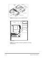
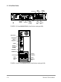
1
Service Manual Panorama® Pat i e n t m o n i to r i n g n e t w o r k 0070-01-0656-01_revD.indd 1 9/30/11 10:32 AM Service Manual Panorama® C E N T R A L S TAT I O N PAT I E N T M O N I TO R I N G N E T W O R K 0070-02-0656-01_revD.indd 1 9/30/11 10:29 AM DPMTM is a trademark of Mindray DS USA, Inc. e-GatewayTM is a trademark of Mindray DS USA, Inc. GatewayTM is a trademark of Mindray DS USA, Inc. HP® is a registered trademark of Hewlett Packard Company. Microsoft®, Windows®, and Windows NT® are US registered trademarks of Microsoft Corporation. Mindray® is a trademark of Shenzhen Mindray Bio-Medical Electronics Co., Ltd. Panorama® is a U.S. trademark of Mindray DS USA, Inc. Passport® is a U.S. registered trademark of Mindray DS USA, Inc. Passport2® is a U.S. registered trademark of Mindray DS USA, Inc. PassportV® is a U.S. registered trademark of Mindray DS USA, Inc Spectrum® is a U.S. registered trademark of Mindray DS USA, Inc. Spectrum OR TM is a U.S. trademark of Mindray DS USA, Inc V SeriesTM is a U.S. registered trademark of Mindray DS USA, Inc. Copyright © Mindray DS USA, Inc., 2015 All rights reserved. Contents of this publication may not be reproduced in any form without permission of Mindray DS USA, Inc. Panorama™ Service Manual This page intentionally left blank. Panorama™ Service Manual Foreword ........................................................................................................................................ iv Warnings, Cautions, and Notes ...................................................................................................... iv Warnings ........................................................................................................................................ iv Cautions ........................................................................................................................................ vi How to Get Help ............................................................................................................................. vii Phone Numbers and How to Get Assistance… .............................................................................. vii Manufacturer's Responsibility ........................................................................................................ vii Instrument Description ................................................................................................................ 1 - 1 Introduction ............................................................................................................................... 1 - 2 Overview ........................................................................................................................... 1 - 2 Panorama telemetry .................................................................................................................. 1 - 2 Core Functions and Components ...................................................................................... 1 - 3 Panorama Block Diagram .................................................................................................. 1 - 4 System Modules, Components, and Peripherals ....................................................................... 1 - 5 Panorama Central Station ................................................................................................. 1 - 5 Network Laser Printer........................................................................................................ 1 - 5 Keyboard, Video, and Mouse (KVM) Extender .................................................................. 1 - 5 Network Ethernet Switches ............................................................................................... 1 - 5 Uninterruptible Power Supply (UPS) ................................................................................. 1 - 5 Access Point (optional 2.4 GHz Telemetry only) ............................................................... 1 - 6 Bedside Monitors .............................................................................................................. 1 - 6 ViewStation(Optional) ....................................................................................................... 1 - 6 WorkStation (Optional) ...................................................................................................... 1 - 9 Gateway/e-Gateway (Optional) ......................................................................................... 1 - 9 Telemetry Server (Optional) .............................................................................................. 1 - 9 Wireless Transceiver (Optional) ........................................................................................ 1 - 9 Theory of Operation .................................................................................................................. 1 - 9 Panorama Central Station and Wireless Telemetry Server ................................................ 1 - 9 Motherboard ............................................................................................................. 1 - 9 Connected to the Motherboard via PCI connectors: ................................................... 1 - 10 Connected to the Riser Card (optional) ..................................................................... 1 - 10 System Hard Drive Assembly ................................................................................... 1 - 10 CD-ROM Drive .......................................................................................................... 1 - 10 Patient Network Interface Card ................................................................................. 1 - 10 AGP Graphics Display Card (if applicable) ................................................................ 1 - 10 ATX Power Supply .................................................................................................... 1 - 10 Disclosure Hard Drives (Central Stations, WorkStations and Gateways Only) ........... 1 - 10 3.5” Floppy Drive (optional) ...................................................................................... 1 - 10 Clock Card (optional) ................................................................................................. 1 - 11 Central Station Displays ................................................................................................... 1 - 11 LCD Display .............................................................................................................. 1 - 11 Audio ......................................................................................................................... 1 - 11 Panorama™ Service Manual i Repair Information ....................................................................................................................... 2 - 1 Introduction ............................................................................................................................. 2 - 2 Safety Precautions ................................................................................................................. 2 - 2 Equipment and Special Tools Required .................................................................................. 2 - 2 Troubleshooting ...................................................................................................................... 2 - 3 Central Station, Display Monitors and Laser Printers ........................................................ 2 - 3 Communication Loss from an Individual Bedside Monitor ................................................. 2 - 5 Communication Loss from All hardwired Bedside Monitors .............................................. 2 - 9 Communication Loss from All 2.4GHz Bedside Monitors................................................... 2 - 9 Communication Loss from WMTS Devices Telemetry Devices ......................................... 2 - 11 Panorama Wireless Telemetry Server ............................................................................... 2 - 13 Disassembly Instructions ........................................................................................................ 2 - 14 Assembly Diagrams ........................................................................................................... 2 - 14 Disassembly Instructions .................................................................................................. 2 - 15 0998-00-0206-10 Telemetry Server Chassis ................................................................ 2 - 18 0998-00-0700-01 Central Station Chassis ................................................................... 2 - 20 0998-00-0705-01 Central Station Chassis ................................................................... 2 - 22 0998-00-0708-01 Central Station Chassis ................................................................... 2 - 23 0998-00-0708-03 Central Station Chassis ................................................................... 2 - 23 0998-00-0709-01 Central Station Chassis ................................................................... 2 - 26 0998-00-0709-03 Central Station Chassis .................................................................... 2 - 28 0998-00-0710-01 Telemetry Server Chassis ................................................................ 2 - 28 0998-00-0190-02 Wireless Transceiver ........................................................................ 2 - 30 Parts Replacement ....................................................................................................................... 3 – 1 Introduction .............................................................................................................................. 3 - 2 Available Replacement Parts and Assemblies ........................................................................ 3 - 2 Product Variations ................................................................................................................... 3 - 2 Parts Pricing Information ........................................................................................................ 3 - 2 Ordering Information ............................................................................................................... 3 - 2 Description and part number .................................................................................................... 3 - 3 Calibration ................................................................................................................................... 4 - 1 Preventative Maintenance ........................................................................................................... 5 - 1 Display Monitors ...................................................................................................................... 5 - 2 LCD Display Chassis ......................................................................................................... 5 - 2 Care and Cleaning of the Screen/Touchscreen ................................................................. 5 - 2 Central Station, Gateways, Telemetry Server and Wireless Transceiver ................................. 5 - 3 Cleaning ........................................................................................................................... 5 - 3 Visual Inspection .............................................................................................................. 5 - 3 Uninterruptible Power Supplies (UPS) ..................................................................................... 5 - 3 Rack Mounted UPS ........................................................................................................... 5 - 3 Desktop and Auxiliary UPS ............................................................................................... 5 - 3 Central Station Network Equipment Racks .............................................................................. 5 - 4 System Maintenance Schedule ................................................................................................ 5 - 4 Preventative/Periodic Maintenance ................................................................................... 5 - 4 ii Panorama™ Service Manual Equipment Configuration ............................................................................................................ 6 - 1 Introduction .............................................................................................................................. 6 - 2 Configuring the Telemetry Server ...................................................................................... 6 - 2 Wired Bedside Monitor Communication Configuration ...................................................... 6 - 3 Passport2 and Spectrum WMTS configuration .................................................................. 6 - 7 Mindray 2.4 GHz monitor configuration ............................................................................. 6 - 8 Appendix A .................................................................................................................................. 7 - 1 Panorama Motherboard CMOS Setup/Verification ................................................................... 7 - 2 Central Station ViewStation WorkStation (0998-00-0701-01, 0998-00-0705-01) .............. 7 - 3 2U Telemetry Server (0998-00-0206-10) .......................................................................... 7 - 5 RM/VM Central Station, ViewStation, WorkStation and Gateway (0998-00- 0708-01, 0998-00-0709-01) ............................................................................................................. 7 - 9 Telemetry Server (0998-00-0710-01) ............................................................................... 7 - 13 e-Gateway 0998-00-0708-03, 0998-00-0709-03 ............................................................... 7 - 16 Appendix B .................................................................................................................................. 8 - 1 Programming & configuring replacement Panorama telemetry devices .................................. 8 - 2 Accessing the Wireless Menu ........................................................................................... 8 - 2 Removing Devices from the system .................................................................................. 8 - 2 Programming a replacement Telepack-608 (0998-00-0191-XX) ....................................... 8 - 3 Programming the Telepack-608 ........................................................................................ 8 - 4 Programming Replacement Instrument Radios (0040-00-0361-XX) ................................. 8 - 4 Programming the Devices ................................................................................................. 8 - 5 Assigning a replacement Telemetry Device to the Central Station .................................... 8 - 5 Assigning a new Telemetry Device to the Central Station ................................................. 8 - 6 Removing a telemetry device from the Equipment List ..................................................... 8 - 6 To re-enter a device after being deleted: ........................................................................... 8 - 6 Appendix C ................................................................................................................................... 9 – 1 Connection Diagrams .............................................................................................................. 9 - 3 Central Stations ................................................................................................................. 9 - 3 View/Work Stations ........................................................................................................... 9 - 4 Telemetry Servers (0998-00-0206-01) .............................................................................. 9 - 4 Wireless Transceiver (0998-00-0710-01) .......................................................................... 9 - 6 Gateway ............................................................................................................................ 9 - 6 e-Gateway ......................................................................................................................... 9 - 6 KVM Extenders ................................................................................................................. 9 - 7 Laser Printers .................................................................................................................... 9 - 11 Ethernet Switches ............................................................................................................. 9 - 12 Panorama™ Service Manual iii Foreword The Panorama™ Service Manual is a guide for technically-qualified personnel who perform maintenance and/or repair on the Panorama Patient Monitoring Network. The Service Manual conveys system-wide information that is divided into sections. For quick reference, each chapter’s title page displays a table of contents that indicates, by sections, the topics covered. This publication may have been updated to reflect product design changes and/or manual improvements. NOTE: Unauthorized servicing may void the remainder of the warranty. Check with the factory or with a local authorized representative to determine the warranty status Warnings, Cautions, and Notes Please read and adhere to all warnings, cautions, and notes listed here and in the appropriate areas throughout this manual. A WARNING is provided to alert the user to potential serious outcomes (death, injury, or serious adverse events) to the patient or the user. A CAUTION is provided to alert the user signaling that special care is necessary for the safe and effective use of the device. They may include actions to be taken to avoid effects on patients or users that may not be potentially life threatening or result in serious injury, but about which you should be aware. A NOTE is provided when additional general information is applicable. WARNINGS WARNING: Do not attempt to use either Panorama ® Patient Network or Central Network, including cabling for any purpose other than its intended use. WARNING: Route cables neatly. Ensure cables are not in the way of patients or hospital personnel. WARNING: Loading any unauthorized software including utilities on Panorama® Patient Monitoring Network will cause the application to no longer be suitable for medical patient monitoring use. WARNING: Do not connect or attempt to connect or reconfigure any equipment to Panorama ® Central Station Patient Network or Central Network LANs unless authorized in writing. This includes all commercially available networking hardware] i.e., switches, routers etc.) or peripherals (i.e., Printers) even if they are the same brand as recommended by the configuration of the system and supplied by the manufacturer. iv Panorama™ Service Manual WARNING: Do not attempt to load any devices or device drivers onto the Panorama® Central Station. If the user connects or attempts to connect any equipment Panorama ® Central Monitoring System may not operate as intended. WARNING: Only qualified and trained service personnel or Service personnel should attempt to service equipment. Service is defined as any activity requiring the cover to be removed for internal adjustments, parts replacements, repairs or software upgrades of any kind to insure compatibility. WARNING: To insure compatibility with the operating system and applications software, use only the supplied and/or approved components to repair any part of the Panorama Patient Monitoring Network. Use of unauthorized software, devices, accessories, or cables other than those approved may render the application unsuitable for medical patient monitoring. It may also result in increased electromagnetic Emissions or decreased Immunity of the system. WARNING: Do not block or turn down the volume from the maximum position on the speakers provided with Panorama ® Central Monitoring System. Set the volume levels so that alarms can be heard at all times, as described in the Operation Manual. WARNING: Be careful not to turn off patient alarms. Turning off patient alarms can jeopardize patient safety. WARNING: Do not incinerate batteries, possible explosion may occur. WARNING: The 18.1" flat panel may tip over, if the display head is inclined to an angle greater than 45°backward tilt. If the user elects to have the display head inclined to an angle greater than 45°, backward tilt, the flat panel must be attached to a secure mounting surface via three screw locations on the bottom of the base. WARNING: The Panorama Central Station and the Panorama Telemetry Server must utilize the hospital emergency power system. Failure to do so will result in loss of monitoring during extended periods of power failure. The back-up power time period, for the Panorama Patient Monitoring Network, is limited. Panorama™ Service Manual v WARNING: Do not put MPSO (Multiple Portable Socket Outlets, i.e., multiple outlet extension cords) used with the Panorama Central Station System on the floor. Connect only Panorama Central Station accessories and components to the same MPSO as the Panorama Central Station. Do not overload MPSOs. Use only MPSOs that comply with the requirements of IEC 60601-1-1. WARNING: Do not clean the monitor while it is on and/or plugged in. CAUTIONS CAUTION: This system is intended for use in a hospital or clinical setting and to be operated by trained and authorized personnel who are acting on the orders of a physician. Its purpose is the real time monitoring of a patient's physiological parameters over an extended time frame. CAUTION: For proper operation do not obstruct the fan air holes. CAUTION: For proper operation never place fluids on top of this equipment. In case of accidental spillage, wipe clean immediately and have the system serviced to ensure no hazard exists. CAUTION: For proper operation do not use Panorama Patient Monitoring Network with a frayed or damaged power cord. CAUTION: Do not operate Panorama® or any of its components if they have been dropped or the case has been damaged. CAUTION: Use only the supplied power cords or if a substitute is necessary, only use Hospital Grade power cords. CAUTION: For proper operation use only approved accessories with this product. CAUTION: Dispose of single use items in accordance with hospital policy. CAUTION: Software is written directly to some of the PC boards within the computers. Replacement of the PC boards with off-the-shelf PC boards may compromise the proper operation of the Central Station Network. vi Panorama™ Service Manual How to Get Help Phone Numbers and How to Get Assistance A network of service representatives and factory-trained distributors is available. Before requesting service, perform a complete operational check of the instrument to verify proper control settings. If operational problems continue to exist , In North and South Americas, contact the Service Department at (800) 288-2121, ext: 7875 for arranging a service or (201) 995-8000 for assistance in determining the nearest field service location. In areas other than North and South America, contact Mindray’s agents or Mindray service centers in your region. If Mindray service centers are not available in your region, please contact the Customer Service of Mindray headquarters in Shenzhen at (86) 755 26582492 or (86) 26582888 for technical support or assistance. Please include the instrument model number, the serial number, and a description of the problem with all requests for service. Warranty questions should be directed to a local Mindray representative. Manufacturer's Responsibility Mindray DS USA is responsible for the effects on safety, reliability, and performance of the equipment only if: assembly operations, extensions, readjustments, modifications or repairs are carried out by persons authorized by Mindray; and the electrical installation of the relevant room complies with the appropriate requirements; and the equipment is used in accordance with the instructions for use. Panorama™ Service Manual vii This page intentionally left blank. viii Panorama™ Service Manual 1.0 Instrument Description 1.1 Introduction ....................................................................................................................... 1 – 2 1.2 Panorama Telemetry ......................................................................................................... 1 – 2 1.3 System Modules, Components and Peripherals ............................................................... 1 - 5 1.4 Theory of Operation .......................................................................................................... 1 - 7 Panorama™ Service Manual 1-1 1.1 Introduction This section of the service manual initially provides a high-level overview of the Panorama ® Patient Monitoring Network, followed by more detailed information. 1.1.1 Overview The Panorama Patient Monitoring Network is a comprehensive patient care monitoring and management system designed for use in a hospital setting. The system is intended to be installed and used in a fixed, non portable, permanent location that serves as a central data viewing station. The Panorama Patient Monitoring Network consists of the following four primary modules that are linked to and/or by one another: Panorama Central Station Panorama Central Network Panorama Patient Network Bedside Monitors NOTE: Optional modules include 2.4 GHz telemetry and WMTS telemetry for wireless operation. Hardware and software components within each module provide system-wide functionality and connectivity. Patient information is routed to the Panorama Patient Monitoring Network via the four modules. Information is sent across a network provided to and by the Panorama Patient Network and the Panorama Central Network modules. The Panorama Patient Network connects the Passport 2 ® and PassportV®, Spectrum ® and Spectrum OR®, DPM6, DPM7 and V12 and V21 monitors via a proprietary wired Ethernet network. The monitoring capacity of the system is flexible and uses industry standard components to provide network communications to all connected patient monitors and peripheral devices. The Panorama Central Network connects two or more Panorama Central Stations and/or laser printers. This service manual focuses on the Panorama Central and Telemetry Server modules since they are the hands on interface between the medical staff and the Panorama Patient Monitoring Network. The Panorama Central Station module is a combination of both hardware (e.g., Central Station computer and display monitor) and software components (i.e., Panorama software applications). Much of the patient information processing and data management occurs within the Central Station. 1.2 Panorama Telemetry The Panorama Wireless Telemetry Server collects patient data from Passport V 2.4 GHz, DPM6, 2.4 GHz, Spectrum, Passport2 WMTS bedside monitors and/or Ambulatory Telemetry Packs (Telepack608) via ceiling or wall mounted antennas and/or Access Points. This allows transport through specifically designated areas of the hospital without disconnecting cables or discharging a patient while transporting that patient from room to room. Patient data is displayed at the Central Station, which is mounted at the nurses’ station. The system operates in either the 802.11 g/b band or the 608 - 614 MHz Wireless Medical Telemetry Service (WMTS) band. Each Central Station to display up to 16 patients on dual Touch Screen displays. The Central Station’s monitor is controlled by a set of menu keys that you activate by selecting a key on the Touch Screen monitor, or positioning the cursor over a key and clicking the left mouse button. When you select a menu key, you receive visual feedback. 1-2 Panorama™ Service Manual 1.2.1 Core Functions and Components 1.2.1.1 Wireless Transceiver (WMTS Only) The Wireless Transceiver collects and processes RF data from the antenna network. The transceiver also provides 9 VDC power to the antenna network. The Transceiver can support up can support up to 188 WMTS devices 1.2.1.2 Telemetry Server (WMTS only) The Telemetry Server processes the data from the Wireless Transceiver and sends the patient data to the Patient Network. Each Telemetry Server support up can support up to 47 WMTS devices. 1.2.1.3 Connectivity Each Panorama Central Station is designed for monitoring up to 16 hospital patients. The data is derived from bedside monitors connected to the Panorama Patient Monitoring Network via the Panorama Patient Network (an Ethernet connection). Patient data is received and processed by the Central Station and displayed on an LCD display. A laser printer produces printouts of the patient data via the Panorama Central Network. 1.2.1.4 Wireless Configurations The wireless network configuration is remote from the nurses’ station. Located in a closet, the Panorama Wireless Telemetry Server collects data from patient monitors via antennas and access points. The equipment listed below is also included in the wireless configuration. WMTS (608 - 614 MHz) Telemetry Instrument transceivers (for Passport 2 and Spectrum bedside monitors) Telepack-608 (patient worn transmitter) Telemetry Server Wireless Transceiver Antenna Network Active Antennas RG6 and/or RG11 coax cable RF Splitters Antenna repeaters 2.4 GHz 802.11 b/g Telemetry PassportV and DPM6 monitors with internal wireless modules 802.11 b/g Access Points Power Injectors CAT5e Cable Panorama™ Service Manual 1-3 1.2.2 Panorama Block Diagram The following block diagram illustrates the wired and wireless WMTS and 802.11b/g configurations for the Panorama Patient Monitoring and Central Monitoring Networks. Figure 1-1 Block Diagram 1-4 Panorama™ Service Manual 1.3 System Modules, Components, and Peripherals 1.3.1 Panorama Central Station The Panorama Central Station contains the Panorama Patient Monitoring Network application software, operating system, patient data processing, and data storage components. The application software is stored on the system hard drive within the Panorama Central Station. A separate hard drive stores patient historical data. LCD Monitors provide a graphic display of patient waveforms, audio, and other data. 1.3.2 Network Laser Printer A network laser printer provides ECG Strip and Patient Report printouts. One Panorama Central Station is capable of supporting up to two printers. The following network printers are validated for use with the Panorama Central Station: HP LaserJet 4050n HP LaserJet 4100n HP LaserJet 4200n HP LaserJet 4250n HP LaserJet 4350n HP LaserJet P4015n (software versions 8.6.3 and above) HP LaserJet M602 (software versions 11.3 and above) 1.3.3 Keyboard, Video, and Mouse (KVM) Extender The KVM Extender allows display monitors, and mouse to be located away from the Panorama Central Station. The KVM Extender consists of a transmitter and receiver connected via CAT5e cable. The transmitter is located at the Central Station location, and the receiver is located at the display monitor location. Analog signals are carried by CAT5e Ethernet cable and link the Central Station with the display monitor(s). The extenders will support a maximum of 400 ft. (122 m.) of cable distance between the Central Station location and the LCD monitor at the Nurses’ Station. 1.3.4 Network Ethernet Switches Switches route data from bedside monitors and telemetry servers and transfer the data to the Panorama Central Station. Switches also facilitate Central Station-to-Central Station communication, and communication to network laser printers. 1.3.5 Uninterruptible Power Supply (UPS) UPS provides battery backup during a power outage and limited AC surge protection for all Panorama Central Station components (except for a laser printer). Panorama™ Service Manual 1-5 1.3.6 Access Points (optional 2.4 GHz Telemetry only) The Access Point collects patient data transmitted from the bedside monitors and Telepack. 1.3.7 Bedside Monitors 1.3.7.1 Passport2® The Passport 2 monitor is a four-trace vital-signs monitor that can be mounted on a rolling stand, wall mount bracket, or tabletop. For additional information on the Passport2 monitor, refer to the Passport2 Operating Instructions. 1.3.7.2 Spectrum TM The Spectrum monitor is a four-trace vital-signs monitor that can be mounted on a rolling stand, wall mount bracket, or tabletop. For additional information on the Spectrum monitor, refer to the Spectrum Operating Instructions. 1.3.7.3 Spectrum OR TM The Spectrum OR monitor is a three to eight-trace vital-signs monitor that can be mounted on a rolling stand, wall mount bracket, or tabletop. For additional information on the Spectrum OR monitor, refer to the Spectrum Operating Instructions. 1.3.7.4 Passport ® V The Passport V monitor is a three to eight-trace vital-signs monitor that can be mounted on a rolling stand, wall mount bracket, or tabletop. For additional information on the Passport V monitor, refer to the Passport V Operating Instructions. 1.3.7.5 DPM6 and DPM7TM The DPM6 and DPM7 monitors are three to five lead vital-signs monitors that can be mounted on a rolling stand, wall mount bracket, or tabletop. For additional information on the DPM6 and DPM7 monitors, refer to the DPM6 Operating Instructions and DPM7 Operating Instructions. 1.3.7.6 V Series (V12 TM and V21TM) The V12 and V21 monitors are three to five lead vital-signs monitors that can be mounted on a rolling stand, wall mount bracket, or tabletop. For additional information on the V Series monitors, refer to the V Series Operating Instructions. 1.3.8 ViewStation (Optional) The Panorama ViewStation provides the ability to observe any patient on the Panorama network. 1-6 Panorama™ Service Manual 1.3.9 WorkStation (Optional) The Panorama WorkStation provides the ability to observe, admit, and discharge any patient on the Panorama network. 1.3.10 Gateway/e-Gateway (Optional) The Panorama Gateway or e-Gateway provides an interface to the hospital information system. 1.3.11 Telemetry Server (Optional) The Panorama Telemetry Server processes data received from Mindray WMTS devices via the wireless network. 1.3.12 Wireless Transceiver (Optional) The Wireless Transceiver provides DC power to the WMTS antenna network, and provides an interface to the Panorama WMTS wireless network. 1.4 Theory of Operation The Panorama Central Station is an 8, 12 or 16-patient channel, medical monitoring system. The station’s design and monitor are based on the ATX computer architecture. Basic system data processing configuration includes an ATX computer, a LCD display monitor with Touch Screen, and an Ethernet distribution system. CAUTION: The Panorama software is written directly to some of the PC boards within the tower. Replacement of the PC boards with off-the-shelf PC boards may compromise the proper operation of the Central Station. 1.4.1 Panorama Central Station and Wireless Telemetry Server Each of the Panorama Central Station’s hardware/software items (e.g., hard drives, controls, etc.,) are identified and detailed below. Functionality and connectivity for each component and/or peripheral is mentioned where appropriate. Specified for each is its contribution(s) to either the overall Panorama Patient Monitorin g Network and/or to data management operations designated by system architecture for the Central Station module. 1.4.1.1 Motherboard The motherboard is the physical platform on which the computer’s electronic circuitry and processors reside. The computer’s Central Processing Unit (CPU) is docked on the motherboard. The CPU executes the Panorama Patient Monitoring Network proprietary software. The following components also reside on the motherboard: Random Access Memory (RAM) Read Only Memory, Basic Input/output System (ROM BIOS) Audio Circuit and Video Circuit EIDE or SATA controller for 3.5” floppy drive (optional), CD-ROM, and system hard drives Patient/Central Network Interfaces Mouse and keyboard controllers Panorama™ Service Manual 1-7 1.4.1.2 Connected to the Motherboard via PCI connectors: Patient Network/Telemetry Network Interface Card AGP Graphics Display Card (if applicable) Riser Card (2U Central cases and 2U Panorama Telemetry Server only) Clock Card (PCI) 1.4.1.3 Connected to the Riser Card (optional) Telemetry Network Interface Card (Panorama Telemetry Server only) TIM PCI Card (Panorama Telemetry Server only) AGP Graphics Display Card 1.4.1.4 System Hard Drive Assembly The system hard drive stores the Windows Operating System and Panorama application software. It is controlled by EIDE controller or SATA controller circuitry on the motherboard. 1.4.1.5 CD-ROM Drive The CD-ROM drive is used to load software, copy error logs and create and load the emergency disk. 1.4.1.6 Patient Network Interface Card The Panorama Patient Network Interface Card (NIC) sits in the J16 slot on the motherboard. It provides a 100 Mbps Ethernet interface for the Panorama Patient Network. 1.4.1.7 AGP Graphics Display Card (if applicable) The AGP Graphics Display card sits in the J19 slot on the motherboard. There are two versions of the graphic display card. The first version has two HD-15 connectors. The second version has one DVI connector and one HD-15 connector. The second version requires the use of a DVI-to-HD-15 adapter. These connectors are cabled to the display monitors or KVM extenders. 1.4.1.8 ATX Power Supply The ATX switching Power Supply provides power for all electronic assemblies within the Panorama Central Station. Regulated voltages are +5, -5, +12, and -12 Volts. The power supply has a universal AC input and is rated for 300 Watts (minimum). 1.4.1.9 Disclosure Hard Drives (Central Stations, WorkStations and Gateways Only) One disclosure hard drive stores all patient data. The IDE or SATA controller on the motherboar d controls the hard drive. 1.4.1.10 3.5” Floppy Drive (optional) A Diskette Drive is used for running diagnostic software and uploading software. It is controlled by Diskette Drive controller circuitry on the motherboard. 1-8 Panorama™ Service Manual 1.4.1.11 Clock Card (Central Stations, Workstations and Gateways only) The clock card acts as the computer’s system time source, bypassing the motherboard’s clock circuit. 1.4.2 Central Station Displays 1.4.2.1 LCD Display All digital and waveform information is displayed on the LCD screen. The unit is powered from an external AC power supply. Video information is transmitted through a VGA cable from the VGA Card or onboard video circuit from the motherboard. Touch Screen The Touch Screen consists of a flat glass plate that fits over the face of a CRT or LCD monitor display, and is an integral part of the monitor. The Touch Screen controller is located inside the monitor housing. A DB -9 serial cable connects each monitor to the Serial Interface Card or Serial Port on the Panorama Central Station. The Touch Screen uses surface acoustic wave (SAW) technology. Principles of Operation Surface acoustic waves (SAW) are mechanical waves that propagate in the surface of the medium in which they are generated. The actual detection and location of a finger touch on a SAW Touch Screen depends on the absorption of a subsection of the Touch Screen’s SAW energy by the finger touching the screen. The Touch Screen creates an absence of SAW energy. SAW energy is coupled to and extracted from the Touch Screen by four identical piezoelectric transducers and a nearly invisible array of fired -on glass-fit acoustic reflector strips around the border of a glass panel. 1.4.2.2 Audio The internal speakers in the LCD monitor provide the audio feedback of the Central Stations physiological and technical alarms. Panorama™ Service Manual 1-9 This page intentionally left blank. 1 - 10 Panorama™ Service Manual 2.0 Repair Information 2.1 Introduction ....................................................................................................................... 2 – 2 2.2 Safety Precautions ............................................................................................................ 2 – 2 2.3 Equipment and Special Tools Required ............................................................................ 2 – 2 2.4 Troubleshooting ................................................................................................................ 2 – 3 2.5 Disassembly Instructions .................................................................................................. 2 – 14 Panorama™ Service Manual 2-1 2.1 Introduction This section provides the necessary technical information to perform repairs to the system. The most important prerequisites for effective troubleshooting are a thorough understanding of the system functions and the theory of operation. If necessary, refer to the appropriate Panorama Patient Monitoring Network Operating Instructions Manual, which describes instrument functions and features in full detail. 2.2 Safety Precautions In the event the instrument covers are removed, make certain you observe the following warnings and general guidelines: Do not short component leads together. Observe proper anti-static precautions. 2.3 Equipment and Special Tools Required You will need the following equipment and/or special tools when performing repairs: Anti-static Wrist Strap Anti-static Mat #1 Phillips Screwdriver #2 Phillips Screwdriver Slotted Screwdriver 2-2 Panorama™ Service Manual 2.4 Troubleshooting The Central Station’s components can be separated into three (3) sections: Central Station and Displays Networks (Central, Patient, and Wireless) Bedside Patient Monitors and Telemetry Devices During the Central Station’s installation process, a configuration sheet was created to list all IP addresse s, subnet mask numbers, etc. assigned to the Central Station, Panorama Wireless Telemetry Servers and bedside monitors. Refer to that configuration sheet if you cannot retrieve the information from the Central Station, or Panorama Wireless Telemetry Server. If you do not have the list, contact the Service Representative or Authorized Distributor that installed the system. Make sure you have the serial number of the Central Station or Panorama Wireless Telemetry Server when calling. Prior to troubleshooting a network problem, you should check the following areas: All AC and DC power connections are secure. All Ethernet cable connections are secure. Affected cable runs should be tested with a cable tester for continuity. IP addresses: Valid Patient Network, Central Network and Wireless Network IP addresses should be verified. 2.4.1 Central Station and Displays The Central Station display does not power up. Verify that AC power is ON at the Central Station. On the LCD display, turn off the power switch and turn it back on. If No Signal is displayed on the screen, no video signals are reaching the display. Verify that the VGA cable between the display and the computer is making a good connection, and that the connector screws are tight. If the problem persists, it is likely due to a problem within the tower. Reboot the Central Station. Verify that the power and hard drive LEDs are illuminated and the fans are operating. If the display still does not come on, the problem is likely within the tower. If the hard drive LED does not illuminate, the problem is likely related to the CPU or the motherboard. If the fans are not operating, the problem is likely the power supply. KVM extender Verify DC power to both the KVM transmitter and receiver. Check the status of the power LED on both the transmitter and receiver. The power LED should be illuminated and on steady (i.e., not flashing). If the LEDs are flashing or dim, this an indication of loss of connection between the transmitter and receiver, or a failure of one or both of the power supplies. Panorama™ Service Manual 2-3 The display powers up but the Central Station does not complete “self-test”. Note at which point the unit stopped during the boot-up self-test (e.g., passed through the memory check, CMOS check, Drive check). This may mean replacement of the Network Interface Card, the Mother PCB, or one of the hard drives. The unit went through self-test, but did not get to the Panorama operating screen. It stays at the blue screen with no desktop icons Clear the error and event logs (contact a Mindray NA Service Representative or Mindray NA Technical Support for assistance) and save the config tool The mouse does not function. Verify that the connections at the rear of the Central Station are secure and that they are in the appropriate locations. Check connections to the KVM Extender (Transmitter & Receiver). Re-power the KVM by disconnecting AC power from the transmitter and receiver. Reboot the system. Is the mouse functional? If not, install a new PS2 mouse and reboot the system again. Is the mouse functional now? If not, this may mean replacement of the Mother PCB. No touch screen response. Clean the touch screen panel. Verify that the connections at the rear of the Central Station are secure and that they are in the appropriate locations. Check connections to the KVM Extender (Transmitter & Receiver). Re-power the KVM by disconnecting AC power from the transmitter and receiver Reboot the system. Is the touch screen functional? If not, this may mean replacement of the touch screen monitor or the touch screen controller card. Laser printer does not print when requested. Check the Print Setup menu on the Panorama Verify the printer settings on the Panorama are enabled for reports and strips Verify and correct any error messages on the printer's Control Panel LCD. Print the laser printers configuration page. Check the configuration of the Laser printer’s jetdirect card for the correct IP address. Mindray uses 7.7.7.XX for the central network IP address scheme. Verify that the printer can print a test page using the printer's control panel menu. Verify that the cable connections are secure between the printer and the Central Station. If a switch is installed, check the cable connections between the switch and the Central Network connector at the rear of the Central Station. Verify the cable connection between the printer and the switch. Verify the LED is illuminated on the network interface card on the laser printer. If a switch is installed, verify that the Power/Self Test LED is illuminated on the switch. Verify the behavior of the activity LEDs at the port in which each cable is connected and the connected device is active. The LEDs should be blinking. If all of the above are correct, the problem is likely not in the printer. 2-4 Panorama™ Service Manual 2.4.2 Troubleshooting Bedside Communication Issues 2.4.2.1 Communication Loss from an individual Bedside Monitor Wired Network Connection (Passport2, Spectrum, Spectrum OR) Verify the cable connections between the switch and Central Station, and ensure the connection at the tower is at the Patient Network connector. Verify the Power LED on the switch is illuminated. Verify the activity LEDs are illuminated in conjunction with the port in use. If not, disconnect the cable and plug it into another port. Verify the LED of the new port illuminates and show activity Verify the bedside monitor is connected via a patch cable to the CAT5e wall jack. Verify the Link LED on the Comm Port on the bedside monitor is illuminated. If the Link LED does not illuminate, it may indicate that the Comm Port is defective. Verify a "V" in the communication status box (located in the lower right corner of the display) on the bedside monitor, which indicates communication with the Central Station. See Figure 2-1. FIGURE 2-1 Passport2, Spectrum and Spectrum OR Communication Status Icon indicators Connected Disconnected No Icon is displayed Panorama™ Service Manual 2-5 PassportV Verify the bedside monitor is connected via a patch cable to the CAT5e wall jack. Verify a patch CAT5e patch cable is connected to the Ethernet Port (CS1) on the rear of the PassportV Check the status of the Central station icon in the lower right corner of the display (SEE Figure 2-2) FIGURE 2-2 PassportV Communication Status Icon indicators Connected Disconnected 2-6 Blank (no CS icon) Panorama™ Service Manual DPM 6 and DPM 7 Verify the bedside monitor is connected via a patch cable to the CAT5e wall jack. Verify a patch CAT5e patch cable is connected to the Ethernet Jack on the rear of the DPM 6 or DPM7 Check the status of the Central station icon in the lower right corner of the display (see figure 2-3). FIGURE 2-3 DPM 6 and DPM 7 Communication Status Icon indicators Connected Panorama™ Service Manual Disconnected 2-7 V 12 and V21 If Network Communication Lost is displayed (see figure 2-4) FIGURE 2-4 V Series Monitor Verify the V Dock is connected to AC power Verify the bedside monitor is connected via a patch cable to the CAT5e wall jack. Verify a CAT5e patch cable is connected to the Ethernet Jack (marked CS1) on the rear of the V Dock. Verify the Link (yellow solid) and Activity (green blinking) LEDs are illuminated on the rear of the V dock. 2.4.3 Wireless Connections 2.4.3.1 Passport2 and Spectrum WMTS Verify the Radio Icon is displayed along with a V in the communication status box in the lowe r right corner of the display) If the radio icon is not displayed, verify that the bedside monitor is properly configured with WMTS Enabled (located in the Installation Menu of the Passport2 or Spectrum) If the bedside monitor is configured properly, verify the software version of the bedside. If the bedside monitor is configured properly and the software version is the correct version, reprogram the radio card. FIGURE 2-5 Passport2 and Spectrum 2-8 Panorama™ Service Manual Communication Status Icon indicators Connected Disconnected 2.4.3.2 Telepack-608 (WMTS) Verify the device ID of the Telepack 608 is entered to the Central Station's equipment list. Connect all leads to an ECG simulator and then install two (2) new “AA” batteries into the Telepack. Once batteries are installed, verify that the LED display powers up in the following sequence: LA, RA, All connected leads, Link status and battery status If the device did not power up in the preceding sequence, press the test button on the transmitter. If the Link Status LED and/or Battery LED do not illuminate, that indicates a fault within the transmitter. If, however, after pressing the test button, the LED display illuminated in the following sequence: LA, RA, LL, then that indicates the transmitter has not been programmed. Refer to Appendix B for instructions on programming the Telepack. Battery LED Blinking indicates less than 2 hours of run time remaining. Link LED Blinking indicates an internal failure and must be serviced. 2.4.4 Mindray 2.4 GHz Monitors PassportV FIGURE 2-6 PassportV Connected Panorama™ Service Manual Disconnected 2-9 DPM6 FIGURE 2-7 DPM 6 Connected Disconnected 2.4.5 Communication Loss from all wired Bedside Monitors and Mindray 2.4 GHz equipped monitors Wired Network Verify AC power to the Ethernet switch(es). Verify the Power and Status LEDs on the switch(es). Reboot the switch(es). Verify the Status LED for the port connecting the Central Station to the switch. If not illuminated, connect the patch cable to another port on the switch. If the Status LED still does not illuminate, the problem may be with the network card in the Central Station. Verify the LEDs on the Patient Network card on the Central Station. If not illuminated, the network card may be defective. 2 - 10 Panorama™ Service Manual 2.4.6 Communication Loss from all WMTS Telemetry devices 2.4.6.1 Panorama Wireless Transceiver Check the status LEDs on the Panorama Wireless Transceiver. If the Status LED (blue) is illuminated, an internal error in the Wireless Transceiver has occurred. with the main board If the Status LED (blue) is blinking, they is probably a problem with the power supply If the Fault LED (red) is illuminated, this indicates an internal error has occurred within the Wireless Transceiver or a short in the antenna network. The Wireless Transceiver and Telemetry Server must be rebooted to clear the error. If the Power (green) and Configured (yellow) LEDs are not illuminated, check if AC power is connected. If power is connected, disconnect the AC cord and check the fuse in the power entry module. Re boot the Panorama Wireless Transceiver and check the status of the LEDs. If the Power (green) and Configured (yellow) LEDs are illuminated, check the power LED on the antennas. If the LED is not illuminated on the antennas, this indicates that no 9 VDC is being provided by the Panorama Wireless Transceiver to the antenna grid. Each branch of the antenna grid (Main and Diversity) has its own 9 VDC source. Check the output of each branch at the BNC connector for 8.5 VDC to 9 VDC. If either branch is less than 9 VDC, leave the branch disconnected for a short period of time until the 9 VDC level returns. If the 9 VDC does not return to normal, reboot the Server and measure again. If there is no 9V DC after a reboot, open the cover on the Transceiver and measure the Voltage on the output of Power supply at TP1 (-) and TP2 (+). It should be 9 VDC. Replace the power supply if there is no 9 VDC. After rebooting and reconnecting the antennas, the antenna grid again loses 9 VDC, there may be a short in the antenna system or the there is a problem within the Panorama Wireless Transceiver. 2.4.6.2 Panorama Wireless Telemetry Server If the Server is configured properly and communicating with the Wireless transceiver, the Server displays the following text. FIGURE 2-8 Server and Transceiver Communication established Panorama™ Service Manual 2 - 11 When the Server completes the connection to the Central Station network, the following screen will be displayed. FIGURE 2-9 Confirmation of Server and Central Station Communication If the “CB Server Created” message does not appear, the Server is not communicating with the Central Station. Check the cabling between the Server and the Central Station. If the Panorama Wireless Telemetry Server is communicating with the telemetry devices, and the teleme try devices are properly programmed and assigned to the equipment list, the Server displays the following text. FIGURE 2-10 Confirmation of Communications with Telemetry Devices If the "WMTS Telepack Translator Initialized" message does not appear, the telemetry device may not be in the Central Station's equipment list or the Server WMTS devices file. If the telemetry devices are communicating with the Central Station, the Server displays the following text. 2 - 12 Panorama™ Service Manual FIGURE 2-11 Confirmation of WMTS device Communications Verify that each admitted WMTS bedside monitor or Telepack 608 is displayed on the Central Station. Panorama™ Service Manual 2 - 13 2.5 Disassembly Instructions 2.5.1 Assembly Diagrams FIGURE 2-12 Central Station, ViewStation, Workstation, and Gateway (0998-00-0700-XX01) FIGURE 2-13 2U Telemetry Server (0998-00-0206-10) 2 - 14 Panorama™ Service Manual FIGURE 2-14 Central Station ViewStation, WorkStation, and Gateway (0998-00-0705-01) PCI Clock Card VGA Exp. Card Riser Card Motherboard Power Supply System Hard drive CDRW Drive Disclosure Hard drive 0998-00-0708-01 FIGURE 2-15 Central Station, ViewStation, WorkStation, and Gateway (0998-00-0708-01) Panorama™ Service Manual 2 - 15 FIGURE 2-16 e-Gateway, 2U Version (0098-00-0708-03) CDROM Drive + Power Supply + Parallel Conn COM3 COM4 COM2 CPU FAN CPU Feature Conn Front Panel Conn + + Hard Drives ATX/BTX POWER + + ATX12V DDR0 SATA Conn VGA Expansion Card + Clock Card + IDE Conn + CMOS BAT + CLRCMOS + + + + 0998-00-0709-01 FIGURE 2-17 Central Station, ViewStation, WorkStation, and Gateway (0998-00-0709-01) 2 - 16 Panorama™ Service Manual CDROM Drive + Power Supply + Parallel Conn COM3 COM4 COM2 CPU FAN CPU Feature Conn Front Panel Conn + + Hard Drives ATX/BTX POWER DDR1 + + ATX12V DDR0 SATA Conn + Clock Card + NIC Card + IDE Conn CMOS BAT + CLRCMOS + + + + 0998-00-0709-03 FIGURE 2-18 e-Gateway (0998-00-0709-03) TIM PCI Card Riser Card Motherboard Power Supply System Hard drive CDRW Drive 0998-00-0710-01 FIGURE 2-19 Wireless Server (0998-00-0710-01) Panorama™ Service Manual 2 - 17 2.5.2 Disassembly instructions 2.5.2.1 0998-00-0206-10 Telemetry Server Chassis Remove the AC power Cord Disconnect all cables from the rear of the chassis Top cover Remove the 4 screws (2 on each side) from the top cover. Lift off the cover. CD-ROM Drive/Floppy Drive Remove the DC power and IDE cables from the rear of the drives. Remove the 5 screws from the drive bracket. Lift the drive bracket out of the chassis. CD-ROM drive Remove the 4 screws from the drive bracket. Remove the drive. Floppy drive Remove the 4 screws from the drive bracket. Remove the drive. Hard drive Remove the DC power and IDE cables from the rear of the drive. Remove the 2 screws securing the hard drive housing to the chassis. Slide the housing towards the rear of the chassis. Remove the bracket from the chassis. Remove the 4 screws from the sides of the drive housing. Remove the drive from the drive housing. Power Supply Disconnect the 20 pin ATX power connector from the motherboard. Cut any tie-wraps securing the power supply cables to the chassis. Disconnect the 4 pin DC power connector from the hard drive. Disconnect the 4 pin DC power connector from the CD-ROM drive. Disconnect the 4 pin DC power connector from the Floppy Drive. Disconnect the 4 pin DC power connector from the cooling fans. Remove the three screws from the rear of the chassis. Remove the 2 screws securing the supply to the bottom of the chassis. Remove the power supply from the chassis. 2 - 18 Panorama™ Service Manual Network Interface Card Remove the screw securing the expansion card bracket to the chassis. Access is through a hole in the left side panel. Remove the card from the riser board PCI connector. TIM PCI Card Remove the screw securing the expansion card bracket to the chassis. Access is through a hole in the left side panel. Remove the screws securing the card to the bracket connected to the fan assembly. Remove the card from the riser board PCI connector. VGA Card Remove the screw securing the expansion card bracket to the chassis. Access is through a hole in the left side panel. Remove the card from the riser board AGP connector. Riser Card Remove the screws securing the riser card to the stiffener bar. Remove the screws securing the stiffener bar to the chassis. (1 from the rear panel and 1 from the fan bracket.) Loosen the release catch to free the riser card. Remove the riser card assy. from the AGP/PCI motherboard connectors. Motherboard Disconnect the 20 pin ATX power cables from the power supply connector (J29). Disconnect the 2 IDE interface cables from the primary and secondary IDE connectors (J30 and J31). Disconnect the ribbon cable from the floppy drive connector (J27). Disconnect the 4 connectors from the system function connector (J54). Remove the 2 screws securing the stiffener bar to the chassis. (1 from the rear panel and 1 from the fan bracket.) Remove the Network Interface card from the riser card. Remove the VGA card from the riser card. Remove the TIM PCI card from the riser card. Remove the riser card from the motherboard PCI connector. Remove the 10 screws securing the motherboard to the chassis. Remove the motherboard from the chassis Microprocessor removal Disconnect the CPU fan connector from the motherboard (Primary Slot1 Fan J23). Press and loosen the two retaining clips securing the microprocessor to the plastic bracket. Remove the microprocessor. CMOS Battery (BAT1) removal Pry up on the battery to loosen the battery. Remove the battery. Panorama™ Service Manual 2 - 19 2.5.2.2 0998-00-0700-01 Central Station Chassis Remove the AC power Cord Disconnect all cables from the rear of the chassis Top Cover Remove the 4 screws (2 on each side) from the top cover. Lift off the cover. CD-ROM Drive/Floppy Drive Remove the DC power and IDE cables from the rear of the drives. Remove the 5 screws from the drive bracket. Lift the drive bracket out of the chassis. CD-ROM drive Remove the 4 screws from the drive bracket. Remove the drive. Floppy drive Remove the 4 screws from the drive bracket. Remove the drive. Hard drives Remove the DC power and IDE cables from the rear of the drives. Remove the 2 screws securing the hard drive housing to the chassis. Slide the housing towards the rear of the chassis. Remove the bracket from the chassis. Individual drive removal Remove the 2 screws from the left side of the drive housing. Remove the 2 screws from the right side of the drive housing. Remove the drive from the drive housing. Power Supply Disconnect the 4 pin ATX12V and the 20 pin ATX power connector from the motherboard. Cut any tie-wraps securing the power supply cables to the chassis. Disconnect the 4 pin DC power connector from each hard drive. Disconnect the 4 pin DC power connector from the CD-ROM drive. Disconnect the 4 pin DC power connector from the Floppy Drive. Disconnect the 4 pin DC power connector from the cooling fans. Remove the three screws from the rear of the chassis. Remove the 2 screws securing the supply to the bottom of the chassis. Remove the power supply from the chassis. VGA Card Remove the screw securing the expansion card bracket to the chassis. Access is through a hole in the left side panel. Remove the card from the riser board AGP connector. 2 - 20 Panorama™ Service Manual Riser Card Remove the 2 screws securing the riser card to the stiffener bar. Remove the 2 screws securing the stiffener bar to the chassis. (1 from the rear panel and 1 from the fan bracket) Remove the stiffener bar. Loosen the release catch to free the riser card. Remove the riser card assy. from the motherboard AGP1/PCI1/PCI2 connectors. Motherboard Disconnect the 4 pin ATX12V and the 20 pin ATX power cables from the power supply connectors (J10 and J12). Disconnect the 2 IDE interface cables from the primary and secondary IDE connectors (IDE1 and IDE2). Disconnect the ribbon cable from the floppy drive connector (FDD1). Disconnect the ribbon cables from the 3 Serial port connectors (J11, J15 and J16). Disconnect the 5 connectors from the system function connector (J20). Remove the VGA card from the riser card. Remove the screw securing the expansion card bracket to the chassis. Access is through a hole in the left side panel. Remove the bracket. Remove the riser card from the motherboard PCI connector. Remove the 10 screws securing the motherboard to the chassis. Remove the motherboard from the chassis Microprocessor removal Unplug the CPU fan connector from the motherboard. Lift the 2 heat sink/fan assembly retention clips. If necessary, remove the power supply for access to the clips. Remove the Fan assembly. Lift the CPU socket locking lever. Remove the microprocessor. CMOS Battery (BAT1) removal Press the metal latch on the battery holder to free the battery. Remove the battery. Panorama™ Service Manual 2 - 21 2.5.2.3 0998-00-0705-01 Central Station Chassis Remove the AC power Cord Disconnect all cables from the rear of the chassis Front Panel Grasp the Front Panel at the cutout in the bottom of the front panel. Pull out and up to remove. Left side cover Remove the 2 screws from the rear of the left side panel. Pull the cover towards the rear of the unit. Auxiliary Fan (Front Panel) Remove the DC power connector from the FAN3 connector on the motherboard Remove the 4 screws securing the fan to the chassis. Remove the fan. Auxiliary Fan (Rear Panel) Remove the DC power connector from the FAN2 connector on the motherboard Remove the 4 screws securing the fan to the chassis. Remove the fan. CD-ROM Drive Remove the DC power and IDE cables from the rear of the drive. Remove the 2 screws from the left side of the drive. Press and hold the retainer clip on the front of the chassis. Pull the drive out through the front of the chassis. Floppy Drive/Hard drive Remove the DC power and IDE cables from the rear of the drives. Remove the 1 screw from the left side of the drive housing. Remove the 2 or 3 screws from the front of the chassis. Pull the drive housing out through the front of the chassis. Individual drive removal Remove the 2 screws from the left side of the drive housing. Remove the 2 screws from the right side of the drive housing. Remove the drive from the drive housing. Power Supply Disconnect the 4 pin ATX12V (J12) and the 20 pin ATX power (J10) connectors from the motherboard. Remove the 4 pin DC power connector from each installed drive. Cut any tie-wraps securing the power supply cables to the chassis. Remove the four screws from the rear of the chassis. Remove the power supply from the chassis. 2 - 22 Panorama™ Service Manual VGA Card Remove the screw securing the expansion card bracket to the chassis. Press down on the locking tab to free the card. Remove the card from the motherboard’s AGP connector. Motherboard Disconnect the 4 pin ATX12V and the 20 pin ATX power cables from the power supply connectors. Disconnect the 2 80 pin or 40 pin IDE interface cables from the Primary (IDE1) and Secondary (IDE2) IDE connectors. Disconnect the 34 pin ribbon cable from the FDD1 connector. Disconnect the ribbon cables from the 3 COM port connectors). Disconnect the 4 connectors from the front panel connector. Remove the 2 Serial port expansion brackets from the chassis. Remove the 10 screws securing the motherboard to the chassis. If necessary, remove the 6 standoffs and washers from the rear of the chassis securing EMI shield to the motherboard. Remove the motherboard from the chassis. Microprocessor removal Unplug the CPU fan connector from FAN1 connector the motherboard. Remove the 4 screws securing the fan to the heat sink. Remove the fan. Remove the 4 screws securing the heat sink. Remove the heat sink assembly. Lift the CPU socket locking lever. Remove the microprocessor. CMOS Battery (BAT1) removal Press the retaining clip towards the outside of the motherboard. Remove the battery. 2.5.2.4 0998-00-0708-01 0998-00-0708-03 0998-00-0710-01 Central Station ViewStation WorkStation eGateway Wireless Server Chassis Remove the AC power Cord Disconnect all cables from the rear of the chassis Top Cover Remove the 4 screws (2 on each side) from the top cover. Lift off the cover. CD-ROM Drive Remove the power and IDE cables from the rear of the drive. Remove the 6 screws from the drive bracket. Remove the 4 screws from the drive bracket. Remove the drive. Panorama™ Service Manual 2 - 23 Hard drive Remove the power and SATA cables from the rear of the drive. Remove the 2 screws securing the hard drive housing to the chassis. Slide the housing towards the rear of the chassis. Remove the bracket from the chassis. Individual drive removal Remove the 2 screws from the left side of the drive housing. Remove the 2 screws from the right side of the drive housing. Remove the drive from the drive housing. Power Supply Disconnect the 4 pin ATX12V and the 20 pin ATX power connector from the motherboard. Cut any tie-wraps securing the power supply cables to the chassis. Remove the DC power connector from each hard drive. Remove the 4 pin DC power connector from the CD-ROM drive. Disconnect the 4 pin DC power connector from the cooling fans. Remove the three screws from the rear of the chassis. Remove the 2 screws securing the supply to the bottom of the chassis. Remove the power supply from the chassis. VGA Expansion Card (Central Stations View/WorkStations only) Remove the screw securing the expansion card bracket to the chassis. Remove the bracket Remove the card from the motherboard PCI connector. Clock Card (PCI) Central Station, View/Workstations, gateways only) Remove the screw securing the expansion card bracket to the chassis. Remove the clock card from the riser board PCI connector Riser Card (Remove the PCI clock card from the riser card. Remove the screw securing the riser card to the stiffener bar. Remove the riser card from the motherboard PCI connector. Clock Card assembly Remove the screw securing the card bracket to the chassis. Remove the ribbon cable connecting the clock card assembly to the motherboard feature connector. 2 - 24 Manual Panorama™ Service Motherboard Disconnect the 4 pin ATX12V and the 20 pin ATX power cables from the power supply connectors. Disconnect the 2 SATA interface cables. Disconnect the ribbon cable from the parallel port connector. Disconnect the ribbon cable from the IDE connector. Disconnect the ribbon cables from the 3 COM port connectors. Disconnect the 3 connectors from the front panel connector. Remove the clock card from the riser card. Remove the riser card from the motherboard PCI connector. Remove the VGA expansion card from the motherboard. Remove the 6 screws securing the motherboard to the chassis. Remove the motherboard from the chassis. If necessary, remove the 2 screws securing the stiffener bar to the chassis. (1 from the rear panel and 1 from the fan bracket.) Microprocessor removal Unplug the CPU fan connector from the motherboard. Lift the 2 fan retention clips. Remove the Fan assembly. Lift the CPU socket locking lever. Remove the microprocessor. CMOS Battery (BAT1) removal Press the retaining clip towards the outside of the motherboard. Remove the battery. Remove the 4 screws from the drive bracket. Remove the drive. Panorama™ Service Manual 2 - 25 2.5.2.5 0998-00-0709-01 0998-00-0709-03 Central Station and Gateways Chassis Top cover Remove the AC power Cord Remove the 2 screws from the rear of the left side panel. Pull the cover towards the rear of the unit. Front Panel Grasp the Front Panel at the cutout in the bottom of the front panel. Pull out and up to remove. CD-Rom Drive (IDE) Remove the power and IDE cables from the rear of the drive. Remove the 2 screws from the left side of the drive. Press and hold down the retainer clip on the front of the chassis. Pull the drive out through the front of the chassis. CD-Rom Drive (SATA) Remove the power and SATA cables from the rear of the drive. Remove the 6 screws from the drive bracket. Lift the drive bracket out of the chassis. Remove the 4 screws from the drive bracket. Remove the drive. Hard drives Remove the power and SATA cables from the rear of the drives. Remove the screw from the left side of the drive housing. Remove the 2 screws from the front of the chassis. Pull the drive rack out through the front of the chassis. Individual drive removal Remove the 2 screws from the left side of the drive housing. Remove the 2 screws from the right side of the drive housing. Remove the drive from the drive housing. Power Supply Disconnect the 4 pin ATX12V and the 20 pin power connector from the mother board. Remove the power connector from each hard drive. Remove the power connector from the CD-Rom drive Cut any tie-wraps securing the power supply cables to the chassis. Remove the four screws from the rear of the chassis. Remove the power supply from the chassis. Network card (NIC) Remove the screw securing the expansion card bracket to the chassis. Remove the card from the mother board connector. Clock Card (PCI) Remove the screw securing the expansion card bracket to the chassis Remove the Clock card from the motherboard 2 - 26 Panorama™ Service Manual Clock Card Assy. Remove the screw securing the expansion card bracket to the chassis. Remove the ribbon cable from the motherboard feature connector. Mother Board Remove the 2 cables from the power supply connectors. Remove the SATA data cables. Remove the ribbon cable from the parallel port connector. Remove the ribbon cable from the IDE connector. Remove the ribbon cables from the 3 COM port connectors. Remove the 3 connectors from the front panel connector. Remove all PC cards from the mother board connectors. Remove the 6 screws securing the mother board to the chassis. Remove the mother board from the chassis. Panorama™ Service Manual 2 - 27 2.5.2.6 0998-00-0710-01 Telemetry Server Chassis Remove the AC power Cord Disconnect all cables from the rear of the chassis Top cover Remove the 4 screws (2 on each side) from the top cover. Lift off the cover CD-ROM Drive Remove the DC power and IDE cables from the rear of the drive. Remove the 5 screws from the drive bracket. Lift the drive bracket out of the chassis. Remove the 4 screws securing the drive to the drive bracket. Remove the drive Hard drive Remove the DC power and SATA cables from the rear of the drive. Remove the 2 screws securing the hard drive housing to the chassis. Slide the drive housing towards the rear of the chassis. Remove the housing from the chassis. Remove the 2 screws from the left side of the drive housing. Remove the 2 screws from the right side of the drive housing. Remove the drive from the drive housing. Power Supply Disconnect the 4 pin ATX12V and the 20 pin ATX power connector from the motherboard. Cut any tie-wraps securing the power supply cables to the chassis. Remove the DC power connector from the hard drive. Remove the 4 pin DC power connector from the CD-ROM drive. Disconnect the 4 pin DC power connector from the cooling fans. Remove the three screws from the rear of the chassis. Remove the 2 screws securing the supply to the bottom of the chassis. Remove the power supply from the chassis. TIM PCI Card Remove the screw securing the expansion card bracket to the chassis. Access is through a hole in t he left side panel. Remove the 2 screws securing the card to the bracket connected to the fan assembly. Remove the card from the riser board PCI connector. Riser Card Remove the screw securing the riser card to the stiffener bar. Remove the riser card from the motherboard PCI connector. 2 - 28 Panorama™ Service Manual Motherboard Disconnect the 4 pin ATX12V and the 20 pin ATX power cables from the power supply connectors. Disconnect the SATA interface cable. Disconnect the ribbon cable from the IDE connector. Disconnect the 4 connectors from the front panel connector. Remove the riser card from the motherboard PCI connector. Remove the 2 screws securing the stiffener bar to the chassis. (1 from the rear panel and 1 from the fan bracket.) Remove the stiffener bar. Remove the 6 screws securing the motherboard to the chassis. Remove the motherboard from the chassis. Microprocessor Disconnect the CPU fan connector from the motherboard (Primary Slot1 Fan J23). Press and loosen the two retaining clips securing the fan assembly to the plastic bracket. Remove the fan assembly. Lift the retaining arm to free the microprocessor from the socket. Remove the microprocessor. CMOS Battery (BAT1) Pry up on the retaining clip to loosen the battery. Remove the battery. Panorama™ Service Manual 2 - 29 2.5.2.7 Wireless Transceiver Disconnect the AC power cord. Disconnect all cables from the front and rear panels, noting their original locations. 11 6 9 5 8 12 4 10 7 13 3 1 2 1. A RF Input Connector 2. B RF Input Connector 3. High current 9 VDC connector 4. 5/12 V DC connector 5. Font Panel LED Connector 6. AC Input Module and fuse 7. Fan Assembly 8. Power Supply 9. Power Supply Screws 10. Fan Screws 11. Rear connector screws 12. TIM Transceiver Board 13. Top Cover Screws Top Cover Remove the top cover by removing the 20 screws. Power Supply Disconnect the AC input cable from SK2. Remove the four external screws securing the Power Supply to the chassis. Unlock and disconnect the 10 pin connector (marked PUS) from SK1. Disconnect the black and red wires from TB1 (black) and TB2 (red). 2 - 30 Panorama™ Service Manual TIM Radio Transceiver Board Disconnect the LED cable from J130. Unlock and disconnect the 5/12 V DC connector (marked TIM) from J101. Disconnect the 9V DC connectors from J1, noting their original locations. Disconnect the RF coax cables from J2 (A) and J3 (B). Remove the screws securing DS1 thru DS4 to the rear panel. Remove the screws securing the PC board to the chassis. Carefully remove the PC board from the chassis. Internal Fan Remove the 4 screws and nuts securing the fan to the side panel. Disconnect the white and black power AC terminals from the fan. Panorama™ Service Manual 2 - 31 This page intentionally left blank. 2 - 32 Panorama™ Service Manual 3.0 Parts Replacement 3.1 Introduction ....................................................................................................................... 3 - 2 3.2 Available Replacement Parts and Assemblies .................................................................. 3 - 2 3.3 Product Variations ............................................................................................................. 3 - 2 3.4 Parts pricing information ................................................................................................... 3 - 2 3.5 Ordering Information ......................................................................................................... 3 - 2 3.6 Parts description by assembly number ............................................................................. 3 - 3 Panorama™ Service Manual 3-1 3.1 Introduction This section of the service manual contains a list of replacement parts for the Panorama Patient Monitoring Network. 3.2 Available Replacement Parts and Assemblies Replacement parts at a board or assembly level are available. In most cases, individual components on boards and assemblies are not available. Contact the Service Department or your local authorized Service Representative for additional details. Panorama printed circuit boards make extensive use of multi-layer and surface-mount technology. Individual component replacement is not recommended on these boards. Board replacement is the most efficient method of repair for these types of assemblies. 3.3 Product Variations Product variations, due to differences in line voltages or option differences, may require different components. These variations are reflected, where necessary, on the parts lists. 3.4 Parts Pricing Information Current replacement parts and pricing is determined by contacting the Order Entry Department. 3.5 Ordering Information Please follow these guidelines when ordering replacement items for the Panorama Patient Monitoring Network. Include the unit's model and serial number. Include the software revision. Include the part number exactly as it appears in the parts list. Include the description of the part. NOTE: The Mindray maintains a policy of continuous development of product improvement and reserves the right to change materials, specifications and prices without notice. Individual assemblies may contain a different part number for the same item. Reference the 0998-XX-XXXX-XX assembly number when ordering parts and assemblies. The following tables list the parts and part numbers associated with the individual chassis or assembly. 3-2 Panorama™ Service Manual 3.6 Parts description by assembly number 0998-00-0700-01 2U Chassis (Central, View/Workstation or Gateway) PT serial number prefix Description Part Number Power Supply, 500W ATX min. Mother Board ATX Pentium 4 (refurbished) Riser Card PCI/AGP/PCI Video Card, AGP Floppy Disk Drive 3.5 inch CD-RW Drive (IDE) System Hard Drive 80GB min. (IDE) Disclosure Hard Drive 200 /250 GB min. (IDE) Microprocessor Pentium 4 2.4 GHz Memory Module 512 MB Heat Sink w/Fan P4 Cable, Floppy drive Cable, Ultra ATA IDE Drive 2 ft. CMOS Battery (3VDC) 0014-00-0062-01 0671-UC-0052-01 0671-00-0054-01 0671-00-0220-02 0992-00-0121 0992-00-0178-01 0992-00-0084-06 0992-00-0204-01 0992-00-0205-01 0671-00-0053-01 0992-00-0211-01 0012-00-1354 0012-00-1546-01 0146-00-0078 0998-00-0705-01 Vertical Chassis (Central, View/Workstation or Gateway) EU serial number prefix Description Part Number Power Supply, ATX 460 Watt min. Mother Board ATX Pentium 4 Video Card, AGP Floppy Disk Drive 3.5 inch CD-RW Drive (IDE) System Hard Drive 80GB min. (IDE) Disclosure Hard drive 200 GB min. (IDE) Microprocessor Pentium 4 2.8 GHz Memory Module 512 MB Fan, Chassis 90mm Fan Microprocessor Cable, Ultra ATA IDE Drive 2 ft. Cable, Floppy drive CMOS Battery (3VDC) 0014-00-0075-01 0671-00-0052-01 0671-00-0220-02 0992-00-0121 0992-00-0178-01 0992-00-0084-06 0992-00-0204-01 0992-00-0205-01 0671-00-0053-01 0119-00-0214-03 0992-00-0229-01 0012-00-1546-01 0012-00-1354 0146-00-0078 Panorama™ Service Manual 3-3 0998-00-0206-10 Chassis (2U Telemetry Server) WS serial number prefix Description Part Number Power Supply, 500W ATX min. Mother Board Pentium II Riser Card PCI/AGP/PCI Video Card, AGP Network Interface Card TIM PCI Card Floppy Disk Drive 3.5 inch CD-RW Drive (IDE) System Hard Drive 80GB min. (IDE) Microprocessor Pentium II Memory Module 128 MB Cable, Floppy drive Cable, Ultra ATA IDE Drive 2 ft. CMOS Battery (3VDC) 0014-00-0062-01 0671-00-0174-02 0671-00-0054-02 0671-00-0220-02 0671-00-0178-04 0670-00-0744-02 0992-00-0121 0992-00-0178-01 0992-00-0084-06 0992-00-0079 0671-00-0173-01 0012-00-1354 0012-00-1546-01 0146-00-0078 0998-00-0708-01 2U Chassis (Central, View/WorkStation or Gateway) RM Serial number prefix Description Part Number Power Supply ATX 300 W min. Mother Board Intel Dual Core Video Expansion Card CD-RW Drive SATA System Hard Drive 160 GB min. (SATA) Disclosure Hard Drive 250 GB min. (SATA) Microprocessor T2500 Heat sink/Fan Assembly Memory Module 1 GB DDR2 Clock card (PCI) Clock Card Assy. Riser Card CMOS Battery (3VDC) SATA power adapter cable 0014-00-0094 0671-00-0115 0671-00-0116 0992-00-0178-02 use 0992-00-0287 0992-00-0287 0992-00-0285 0992-00-0289 0671-00-0266 0671-00-0267 0671-00-0273 0671-00-0268 0146-00-0078 0012-00-1785 3-4 Panorama™ Service Manual 0998-00-0709-01 Chassis (Central or View/WorkStation) VM Serial number Description Part Number Power Supply ATX 300 W min. Mother Board Intel Dual Core Video Expansion Card CD-RW Drive SATA System Hard Drive 160 GB min. (SATA) Disclosure Hard Drive 250 GB min. (SATA) Microprocessor T2500 Heat sink/Fan Assy. Memory Module 1 GB DDR2 Clock Card (PCI) Clock Card Assy. CMOS Battery (3VDC) 0014-00-0093 0671-00-0115 0671-00-0116 0992-00-0178-01 use 0992-00-0287 0992-00-0287 0992-00-0285 0992-00-0289 0671-00-0266 0671-00-0267 0671-00-0273 0146-00-0078 0998-00-0710-01 Chassis (2U Telemetry Server) TE serial number prefix Description Part Number Power Supply, ATX 300 W min. Mother Board Intel Dual Core CD-RW Drive SATA System Hard Drive 160 GB min. (SATA) Microprocessor T2500 Heat sink/Fan Assembly Memory Module 1 GB DDR2 TIM PCI Card Riser Card CMOS Battery (3VDC) SATA power adapter cable 0014-00-0094 0671-00-0115 0992-00-0178-02 use 0992-00-0287 0992-00-0285 0992-00-0289 0671-00-0266 0670-00-0744-02 0671-00-0268 0146-00-0078 0012-00-1785 0998-00-0708-03 Chassis (2U e-Gateway) RM Serial number prefix Description Part Number Power Supply, ATX 300 W min. Mother Board Intel Dual Core CD-RW Drive SATA System Hard Drive 160 GB min. (SATA) Disclosure Hard Drive 250 GB min. (SATA) Microprocessor T2500 Heat sink/Fan Assembly Clock Card Assy. Memory Card 2 GB DDR2 Network Interface Card Riser Card CMOS Battery (3VDC) SATA power adapter cable 0014-00-0094 0671-00-0115 0992-00-0178-02 use 0992-00-0287 0992-00-0287 0992-00-0285 0992-00-0289 001-000252-00 023-000303-00 023-000262-00 0671-00-0268 0146-00-0078 0012-00-1785 Panorama™ Service Manual 3-5 0998-00-0709-03 Vertical Chassis e-Gateway VM Serial number prefix Description Part Number Power Supply, ATX 300 W min. Mother Board Intel Dual Core CD-RW Drive SATA System Hard Drive 160 GB min. (SATA) Disclosure Hard Drive 250 GB min. (SATA) Microprocessor T2500 Heat sink/Fan Assy. Clock Card Assy. Memory Module 2 GB DDR2 Network Interface Card CMOS Battery (3VDC) SATA power adapter cable 0014-00-0093 0671-00-0115 0992-00-0178-02 use 0992-00-0287 0992-00-0287 0992-00-0285 0992-00-0289 001-000252-00 023-000303-00 023-000262-00 0146-00-0078 0012-00-1785 0998-00-0190-02 (Wireless Transceiver) Description Part Number Fuse GMA 2.5A 250V Power Supply TIM Radio Transceiver Cooling Fan 0159-00-0055-17 0014-00-0060-02 0670-00-0745-01 0119-00-0206 0998-00-0703-01 Repeater Fuse GMA 1.0A 250V Power Supply Cable Repeater PCB 0159-00-0055-12 0014-00-0254-01 0670-00-0776-01 0998-00-0191-XX (Telepack 608) Cap, Battery O-ring (0.756 inch ID) Tether Cover, Serial Port 0380-00-0492-01 0354-02-0018 0380-00-0491-01 0380-00-0477 0040-00-0361-XX (Instrument Radio) Flexible Antenna O-Ring .5 inch ID Note: 0040-00-0361-01 0040-00-0361-02 0992-00-1003 0354-02-0020 Compatible with Panorama Software 8.2.7 and below Compatible with Panorama software 8.3 and above WMTS Antenna Network components Panorama Active antenna 0998-00-0202-02 Telepack Patient Cables and Lead Wires 3-6 Panorama™ Service Manual Description Part Number 3 Wire Patient Cable (Domestic) (Snap) 5 Wire Patient Cable (Domestic) (Snap) V (Brown) Lead (Snap) RA (White) Lead (Snap) LL (Red) Lead (Snap) LA (Black) Lead (Snap) RL (Green) Lead (Snap) Lead wire Plug 0012-00-1503-05 0012-00-1503-02 0012-00-1527-11 0012-00-1527-12 0012-00-1527-13 0012-00-1527-14 0012-00-1527-15 0012-00-1527-31 5 Wire Patient Cable 18” (Pinch) 5 Wire Patient Cable 24” (Pinch) 5 Wire Patient Cable 36” (Pinch) 3 Wire Patient Cable 18” (Pinch) 3 Wire Patient Cable 24” (Pinch) 3 Wire Patient Cable 36” (Pinch) 0012-00-1514-01 0012-00-1514-02 0012-00-1514-03 0012-00-1514-04 0012-00-1514-05 0012-00-1514-06 Disposable Lead wire sets 5 Wire Patient Cable 24” snap (box of 20) 3 Wire Patient Cable 24” snap (box of 20) 040-000746-01 040-000748-01 Panorama Spare parts and accessories Telepack 608 Programming Kit Telepack programming cable 3.3 volt DC power supply Instrument Radio 608 Programming Kit Inst Radio programming cable 5.0 volt DC power supply Mouse, PS/2 Keyboard, PS/2 AC Power Cord (110V Domestic) Patch Cable, CAT5e 6’ straight pinned Patch Cable, CAT5e 10’ straight pinned Patch Cable, CAT5e 10’ cross over Cable, audio 3.5mm stereo 6’ Cable, 9 pin serial M/F (touch screen interface) 0020-00-0485-01 0012-00-1521-01 0014-00-0066-01 0020-00-0486-01 0012-00-1541-01 0014-00-0066-10 0992-00-0233-01 0992-00-0108 0012-25-0001 0012-00-1274-01 0012-00-1274-07 0012-00-1392-05 0012-00-1310 0012-00-1306-10 KVM Extender Longview Companion (Kit) Longview Power Supply Panorama™ Service Manual 0992-00-0150-03 0014-00-0227-01 3-7 LCD Monitors Description Part Number 19 inch ELO model 1928L Touch Desk mount 19 inch ELO model 1928L Touch Wall mount 0160-00-0092-03 0160-00-0092-04 19 inch ELO model 1928L Non Touch Desk Mount 19 inch ELO model 1928L Non Touch Wall Mount 0160-00-0093-03 0160-00-0093-04 LCD Monitor Power Supplies 18 Inch ELO models 1820 and 1825 19 inch ELO models 1926L and 1928L 0014-00-0058 0014-00-0076 SpO2 Module Description Part Number SpO2 Module (no cables) Sensor Starter kit Re-usable Sensor (Ninon) Disposable Sensor interface cable Disposable Sensor (10 pack) 0998-00-0192-01 0020-00-0167 0600-00-0140-01 0012-00-1542-01 0600-00-0139-10 SpO2 Module Spare Parts Button, Latch Dust Cover Spring 3-8 0380-00-0487 0380-00-0477 0214-00-0265 Panorama™ Service Manual 4.0 Calibration There is no internal calibration for Panorama ® Central Station components. Panorama™ Service Manual 4-1 This page intentionally left blank. 4-2 Panorama™ Service Manual 5.0 Preventative Maintenance 5.1 Display Monitors ............................................................................................................... 5 - 2 5.2 Central Station, Gateways, Telemetry Server and Wireless Transceiver .......................... 5 - 3 5.3 Uninterruptible Power Supplies (UPS) .............................................................................. 5 - 3 5.4 Central Station Network Equipment Racks ....................................................................... 5 - 4 5.5 System Maintenance Schedule ......................................................................................... 5 - 4 Panorama™ Service Manual 5-1 5.1 Display Monitors The monitor panel and housing should be cleaned by the user as required, NOTE: Never use an abrasive glass cleaner containing highly concentrated ammonia and strong base chemicals since they damage the surface treatment. WARNING: Do not clean the monitor while it is turned on and/or plugged in. 5.1.1 LCD Display Chassis WARNING: Do not clean the monitor while it is turned on and/or plugged in. WARNING: Do not spray any cleaner directly on a display. It could possibly leak inside the unit and cause damage. Clean the chassis with a lightly moistened soft cloth. 5.1.2 Care and Cleaning of the Screen/Touchscreen For the best performance, it is recommended that the touch screen on the Panorama display(s) be kept clean. You can use any standard glass cleaner to clean the screen. Use a cloth or towel to apply the cleaner. Glass cleaner sprayed directly on a display could possibly leak inside a non-sealed unit and cause damage. Remove fingerprints and stains by using a liquid lens cleaner and a soft cloth. To prevent scratches on the front panel of the display screen, observe the following precautions when cleaning: DO NOT spray any liquids directly on the screen DO NOT use abrasive cleaning materials to clean a touch screen. DO NOT wipe a dry screen. DO NOT use alcohol or chlorinated hydrocarbon solvents. Use a fine soft-hair brush to carefully brush away dust and dirt particles. Use a soft cloth moistened with cleaner solution to wipe the touch screen clean. 5- 2 Panorama™ Service Manual 5.2 Central Station Chassis, Gateways, Telemetry Server Chassis and Wireless Transceiver The external cleaning procedures should only be performed by a qualified electronic technician. 5.2.1 Cleaning Use an anti-static vacuum to carefully remove accumulated dust, dirt, and lint from the various external surface areas. Be careful not to dislodge components, or connectors. 5.2.2 Visual Inspection Perform a visual check to verify that dust, dirt, and lint has been completely removed, and all connectors are secured and all fans are operational. 5.3 Uninterruptible Power Supplies (UPS) 5.3.1 Rack Mounted UPS The battery is designed to last for three (3) to five (5) years under normal use. The UPS performs a self-test automatically every two (2) weeks. If the test fails, the battery LED on the front panel of the UPS will be illuminated. If this occurs, replace the battery cartridge. Refer to the UPS manufacturer’s website for replacement battery cartridge specifications. Instructions for battery replacement are included with the replacement battery cartridge. Mindray does not supply replacement battery cartridges for the UPS. 5.3.2 Desktop and Auxiliary UPS Under normal conditions, the original battery in the UPS will last several years. Each UPS has a self test function to determine the status of the internal battery. 5.3.2.1UPS Model OmniVS800 To run a self-test, leave connected equipment on. With the UPS plugged in and ON, press and hold the button until the UPS beeps (about 2 seconds) then release it. If the batteries are weak, the “Replace Battery” LED will stay lit and the UPS will continue to beep after the test. Refer to the UPS manufacturer’s website for replacement battery specifications. Instructions for battery replacement are included with the replacement battery cartridge. 5.3.2.2 UPS Model ECO750 To run a Self-Test leave connected equipment on. With the UPS plugged in and turned on, press and hold the ON/OFF/TEST button for three seconds. *The alarm will beep once briefly after one second has passed. If the OVERLOAD/CHECK BATTERY LED flashes following a UPS self-test, it may indicate that the battery needs to be replaced. Refer to the UPS manufacturer’s website for replacement battery specifications. Instructions for battery replacement are included with the replacement battery. Panorama™ Service Manual 5-3 5.4 Central Station Network Equipment Racks Use an anti-static vacuum to carefully remove accumulated dust, dirt, and lint from the various external surface areas. Be careful not to dislodge components, or connectors. Verify the mechanical integrity of all cables, wires, and network connections. Replace any frayed or kinked cables. 5.5 System Maintenance Schedule 5.5.1 Preventative/Periodic Maintenance The Preventative Maintenance for the Panorama Patient Monitoring Network will consist of periodic cleaning, inspection and testing. Network Components such as Ethernet switches, KVM switches and extenders, Antennas, and Wireless Access points have no preventative maintenance requirements. Telemetry Packs do not require any preventative maintenance requirement other than cleaning. Refer to Sections 10 and 11 of the Operators Manual for cleaning and testing instructions. Use the following tables for each maintenance procedure: Central Station and Telemetry Server and Equipment Rack Activity Area Cooling fans Power Supply Fans Connections Cases Action Clean Clean Clean Inspect Inspect Technical Level BioMed/CE BioMed/CE BioMed/CE BioMed/CE BioMed/CE UPS Batteries Test BioMed/CE 5- 4 Method Forced air Forced air Forced air See section 5.3 (above) Schedule Annually Annually Annually Annually Annually Annually Panorama™ Service Manual 6.0 Equipment Configuration 6.1 Introduction ....................................................................................................................... 6 - 2 6.1.1 Configuring the Telemetry Server .................................................................................. 6 - 2 6.1.2 Wired Bedside Monitor Communication Configuration ................................................... 6 - 3 6.1.3 Passport2 and Spectrum WMTS configuration .............................................................. 6 - 7 6.1.4 Mindray 2.4 GHz monitor configuration .......................................................................... 6 - 8 Panorama™ Service Manual 6-1 6.1 Introduction This section of the manual covers individual component configuration for the Panorama Patient Monitoring Network. 6.1.1 Configuring the Telemetry Server Turn on the wireless transceiver. Turn on the Telemetry Server and display(s). Enter the Telemetry Server into the Maintenance Mode: Hold down the SHIFT key on the keyboard when the Windows banner is displayed on the monitor. Do not release the SHIFT key until the password Logon screen displays on the monitor. NOTE: The Panorama Server boots into its regular operating mode if no keys are held during the system reboot. The Login information for the Panorama Server's password screen is: LOGON INFORMATION User Name swadmin Password dscpswadmin NOTE: If the login information is incorrectly entered, the Windows login failure is displayed. The Panorama Telemetry Server's Registry Editor Dialog box is displayed if the username/password has been entered correctly. Press the OK button to close the Registry Editor Dialog box and enter the Panorama Server configuration mode. Click on the CB Config Icon. The System Configuration Window will open. Wireless Telemetry Configuration ELAN IP Address Assign the Server an appropriate ELAN IP Address (7.6.6.XXX). Verify that no other device (Central Station, beside monitors, Telemetry Server, or Ethernet Switch) being assigned to the network has the same ELAN IP Address. WELAN IP Address Enabling 608 MHz WMTS Check the option to enable the WMTS Telemetry. 608 MHz WMTS Configuration Select the 608 Band to be used. Deselect any unusable frequencies. Select the downlink RF pair to be used. Select the Global TIM ID and the TIM ID to be used. 6- 2 Panorama™ Service Manual Saving the Configuration 6.1.2 After setting the IP addresses press the Save and Exit button. After a few seconds, a confirmation window appears. Press the YES button to save the settings. The system should reboot at this point. If not, Press the Start button in the lower left corner of the screen. Select Shutdown. Select the Shutdown the Computer option. Press the Yes button to shut down the Server. Wired Bedside Monitor Communication Configuration In order to communicate to the Panorama Central Station, a bedside monitor must be configured for Ethernet protocol and have an IP Address and Subnet Mask address assigned to it. Each bedside monitor must have a different IP address: 7.6.6.3, 7.6.6.4, etc. NOTE: The first 3 octets (X.X.X.) must match the IP address of the ELAN address of the Central Station Network. Passport2, Spectrum, and Spectrum OR FIGURE 6-1 Enter the Installation Menu by pressing and holding the Discharge key during power up. Release the Discharge key when the Installation Menu appears. Set WMTS Enable to No. Go to the System Information Sub-Menu. Set Enable Network to Wired. Enter an IP Address that matches the Patient Network IP Address scheme (e.g., 7.6.6.3). Do not duplicate an existing assigned IP address. Set the Subnet Mask ID to 255.255.255.0. Check the Device ID number. This number will be entered into the Central Station's equipment list. Panorama™ Service Manual 6-3 Make sure neither serial port is set to: VISA with Admit, or PatientNet Save the information by pressing Save Current. Turn off the monitor. PassportV FIGURE 6-2 6- 4 Enter the Installation Menu by pressing and holding the Discharge key during power up. Release the Discharge key when the Installation Menu appears. Go to the Advanced Installation Setup Menu. Set Enable Network to Wired Set Connect to Central Station to Yes Enter an IP Address that matches the Patient Network IP Address scheme (e.g., 7.6.6.3). Do not duplicate an existing assigned IP address. Set the Subnet Mask ID to 255.255.255.0. Check the Device ID number. This number will be entered into the Central Station's equipment list. Select Previous Menu Save the information by pressing Save Current. Press Yes to save the settings. Turn off the monitor. Panorama™ Service Manual DPM 6 and 7 FIGURE 6-3 Enter the Main menu. Select Maintenance then select Factory Maintenance (enter the Passcode 332888) Verify the Central Station type is set to Panorama Go to User Maintenance and the select Network Setup FIGURE 6-4 Verify it is set to LAN Enter an IP Address that matches the Patient Network IP Address scheme (e.g., 7.6.6.3) and press Enter, then press OK Exit back to the normal screen Panorama™ Service Manual 6-5 V Series Monitors Press the Setup button on the V Series monitor’s screen Press the System button, enter the passcode: system and press Enter Press the Network Tab Check the Device ID number. This number will be entered into the Central Station's equipment list. FIGURE 6-5 Press the Wired button. Enter an IP Address that matches the Patient Network IP Address scheme (e.g., 7.6.6.3). Do not duplicate an existing assigned IP address. Set the Subnet Mask ID to 255.0.0.0. FIGURE 6-6 6- 6 Press the Accept button. Press the Accept button again to get back to the main screen. Re-boot the V series monitor. Panorama™ Service Manual 6.1.3 Passport2 and Spectrum WMTS wireless connection FIGURE 6-7 Enter the Installation Menu by pressing and holding the Discharge key during power up. Release the Discharge key when the Installation Menu appears. Set WMTS Enable to Yes. If not available for activation, go to the System Information Sub-Menu. Set Enable Network to No. Go back to the System Information Sub-Menu. Set WMTS Enable to Yes. Make sure neither serial port is set to: VISA with Admit, or PatientNet Save the information by pressing Save Current. Turn off the monitor. Panorama™ Service Manual 6-7 6.1.4 Mindray 2.4 GHz 802.11b/g wireless connection PassportV (with internal wireless adapter installed) Note The PassportV must have the internal wireless card configured with a specific file in order to communicate to the Mindray 2.4 GHz wireless network. Contact Mindray North America’s Technical Services group for more information. FIGURE 6-8 6- 8 Turn off the Passport V. Press and hold the Discharge key on the front panel while powering up the monitor. Release the Discharge key when the Installation Menu is displayed. Rotate the Navigator Knob to navigate and select the Advanced Installation Setup Menu. Set Enable Network to Wireless Set Connect to Central Station to Yes Go to Previous Menu. Select Save Current Panorama™ Service Manual DPM6 (with internal wireless adapter installed) Note: The DPM6 must have the internal wireless card configured by a specific file in order to communicate to the Mindray 2.4 GHz wireless network. Contact Mindray North America’s Technical Services group for more information. Enter the Main menu. Select Maintenance then select Factory Maintenance (enter the Passcode 332888) FIGURE 6-9 Verify the Central Station type is set to Panorama Go to User Maintenance and then select Network Setup FIGURE 6-10 Panorama™ Service Manual 6-9 Enter the Main menu. Verify that the Wireless AP Module is checked. FIGURE 6-11 Go to User Maintenance and then select Network Setup Verify it is set to Wireless AP Enter an IP Address that matches the Patient Network IP Address scheme (e.g., 7.6.6.3) and press Enter then press OK FIGURE 6-12 6- 10 Exit back to the Monitor’s normal screen Panorama™ Service Manual 7.0 Appendix A 7.1 Panorama Motherboard CMOS Setup/Verification .......................................................... 7 - 2 7.1.1 Central Station ViewStation WorkStation (0998-00-0701-01, 0998-00-0705-01) ........... 7 - 3 7.1.2 2U Telemetry Server (0998-00-0206-10) ....................................................................... 7 - 6 7.1.3 RM/VM Central Station, ViewStation, WorkStation and Gateway (0998-00- 0708-01, 0998-00-0709-01) ............................................................................................................ 7 - 9 7.1.4 Telemetry Server (0998-00-0710-01) ............................................................................. 7 - 13 7.1.5 e-Gateway (0998-00-0708-03, 0998-00-0709-03) ......................................................... 7 - 16 Panorama™ Service Manual 7-1 7.1 Panorama Motherboard CMOS Setup/Verification Verify that the VGA and Serial cables are connected between the display(s) and the Central Stat ion. Connect the keyboard and mouse to the Central Station. Place each of the monitor power switches to the ON position. Press and release the Central Station's front panel power switch. Verify that the two LEDs on the front panel are illuminated during the boot-up process. The power LED (green) should be lit continuously. The HD LED (red) will only be lit continuously during the boot -up process and then it will only be lit during hard disk reads. While the Central Station is performing the memory test, press the DELETE key on the keyboard to enter the CMOS Setup menu. Follow the on-screen instructions to move through the menus and setup or verify the CMOS exactly as it appears below. When completed, select SAVE to CMOS and EXIT to enter these settings into memory. Use the following pages to determine the proper CMOS settings for each unit 7.1.1 Central Station ViewStation WorkStation (0998-00-0701-01, 0998-00-0705-01) 7.1.2 2U Telemetry Server (0998-00-0206-10) 7.1.3 RM/VM Central Station, ViewStation, WorkStation and Gateway (0998-00- 0708-01, 0998-00-0709-01) 7.1.4 Telemetry Server 0998-00-0710-01 7.1.5 e-Gateway (0998-00-0708-03, 0998-00-0709-03) 7- 2 Panorama™ Service Manual 7.1.1 Central Station (0998-00-0701-01, 0998-00-0705-01) STANDARD CMOS SETUP Date (mm:dd:yy) Time IDE Primary Master IDE Primary Slave IDE Secondary Master IDE Secondary Slave Drive A Drive B Video Halt On Base Memory Extended Memory Total Memory Set to current Date Set to current Time ** [ST380021A] ** [ST3200822A] ** [LITE-ON LTR-52246S] (or LTR-52327S) None 1.44M, 3.5 in. None EGA/VGA All, But Keyboard 640K 1047552K 1048576K ADVANCED BIOS FEATURES Virus Warning Disabled CPU L1 and L2 Cache Quick Power On Self Test First Boot Device Second Boot Device Third Boot Device Boot Other Device Swap Floppy Drive Boot Up Floppy Seek Boot Up Numlock Status Gate A20 Option Typematic Rate Setting X Typematic Rate (chars/Sec) X Typematic Delay (Msec) Security Option APIC Mode MPS Version Control for OS OS Select For DRAM>64MB Report No FDD For WIN 95 Small Logo (EPA) Show Enabled Enabled Floppy CDROM HDD-0 Enabled Disabled Disabled On Fast Disabled 6 250 Setup Enabled 1.4 Non-OS2 Yes Enabled ADVANCED CHIPSET FEATURES DRAM timing Selectable X CAS Latency Time X Active to Precharge Delay X DRAM RAS# to CAS# Delay X DRAM RAS# Precharge Memory Frequency For System BIOS Cacheable Video BIOS Cacheable By SPD 2.5 7 3 3 Auto Enabled Enabled Panorama™ Service Manual 7-3 Delay Transaction Delay Prior to Thermal AGP Aperture Size (MB) ICH4 LAN ** On-Chip VGA Setting ** On-Chip VGA On-Chip Frame Buffer Boot Display Enabled 16 Min 64 Enabled Enabled 8 MB Auto INTEGRATED PERIPHERALS On-Chip Primary PCI IDE IDE Primary Master PI0 IDE Primary Slave PI0 IDE Primary Master UDMA IDE Primary Slave UDMA On-Chip Secondary PCI IDE IDE Secondary Master PI0 IDE Secondary Slave PI0 IDE Secondary Master UDMA IDE Secondary Slave UDMA USB Controller USB 2.0 Controller USB Keyboard Support AC97 Audio Init Display First IDE HDD block Mode POWER ON Function X Hot Key Power On Onboard FDC Controller Onboard Serial Port 1 Onboard Serial Port 2 UART Mode Select Onboard Parallel Port Parallel Port Mode PWRON After PWR-Fail Onboard Serial Port 3 Serial Port 3 Use IRQ Onboard Serial Port 4 Serial Port 4 Use IRQ Digital I/O Enabled Auto Auto Auto Auto Enabled Auto Auto Auto Auto Enabled Enabled Disabled Auto PCI Slot Enabled BUTTON Only Ctrl-F1 Enabled 3F8/IRQ4 2F8/IRQ3 Normal 378/IRQ7 SPP Off 3E8H IRQ5 2E8H IRQ10 Disabled POWER MANAGEMENT SETUP ACPI Function Power Management Video Off Method Video Off In Suspend Suspend Type Modem Use IRQ Suspend Mode HDD Power Down Soft-Off by PWR-BTTN CPU THRM-Throttling Wake-Up by PCI Card Enabled User Defined V/H Sync+ Blank Yes Stop Grant 3 Disabled Disabled Instant-Off 50.0% Disabled 7- 4 Panorama™ Service Manual Power On by Ring Resume by Alarm Primary IDE 0 IDE 1 Secondary IDE 0 Secondary IDE 1 FDD, COM, LPT Port PCI PIRQ[A-D]# Disabled Disabled Enabled Enabled Enabled Enabled Enabled Enabled PNP/PCI CONFIGURATIONS PNP OS Install Reset Configuration Data Resources Controlled By PCI/VGA Palette Snoop No Disabled Auto(ESCD) Disabled PC HEALTH STATUS CPU Warning Temperature Shutdown Temperature CPU Fan Failure Warning Sys. Fan Failure Warning Aux. Fan Failure Warning Disabled Disabled Enabled Disabled Disabled FREQUENCY/VOLTAGE CONTROL Auto Detect PCI Clk Spread Spectrum Modulated Disabled Enabled Panorama™ Service Manual 7-5 7.1.2 2U Telemetry Server (0998-00-0206-10) STANDARD CMOS SETUP HARD DISKS Primary Master Primary Slave Secondary master Secondary Slave TYPE AUTO AUTO AUTO AUTO SIZE 0 0 0 0 CYLS 0 0 0 0 HEAD 0 0 0 0 PRECOMP 0 0 0 0 Drive A Drive B 1.44 3.5 inch None Video Halt On Base Memory Extended Memory Other Memory Total Memory EGA/VGA All, but keyboard 640K 523264K 384K 524288K SECTOR MODE LBA LBA LBA LBA BIOS FEATURES SETUP Virus warning: CPU Internal Cache External Cache: Quick Power On Self Test: Boot Sequence: Swap Floppy Drive: Boot Up Floppy Seek: Boot Up Numlock Status: Boot Up System Speed: Gate A20 Options: Typematic Rate Setting: Typematic Rate (Chars/Sec): Typematic Delay (Msec): Security Options: PCI/VGA Palettes Snoop: Mps Version Control For Os: Os Select For Dram > 64 Mb: Video Bios Shadow: C8000-Cbfff Shadow: Cc000-Cffff Shadow: D0000-D3fff Shadow: D4000-D7fff Shadow: D8000-Dbfff Shadow: Dc000-Dffff Shadow: Mpc Enable: Mpc Post Boot: Mpb Baud Rate: 7- 6 Disabled Enabled Enabled Enabled CD-ROM, C, A Disabled Disabled On High Fast Disabled 6 250 Setup Disabled 1.4 Non-Os2 Enabled Disabled Disabled Disabled Disabled Disabled Disabled Disabled Disabled 57.6 Panorama™ Service Manual CHIPSET FEATURES SETUP Auto Configuration: Dram Speed Selection: Ma Wait State: EDO Ras# To Cas# Delay: Fast Ras# To Precharge Time: EDO Dram Read Burst: EDO Dram Write Burst: Dram Data Integrity Mode: Auto Configuration: CPU-To-CDI IDE Posting: System Bios Cacheable: Video Bios Cacheable: Video Ram Cacheable: 8 Bit I/O Recovery Time: 16bit I/O Recovery Time: Memory Hole At 15m-16m: Passive Release: Delayed Transation: AGP Aperture Size (Mb): SDRAM Ras-To Cas Delay: SDRAM Ras Precharge Time: SDRAM Cas Latency Time: Auto Detect Dimm/Pci Clk: Spread Spectrum Modulated: Power Management Power Management: Pm Control By Apm: Video Off Method: Video Off After: Modem Use Irq: Doze Mode; Standby Mode: Suspend Mode: HDD Power Down: Throttle Duty Cycle: Zz Active In Suspend: Vga Active Monitor: Soft-Off By Pwr-Bttn: CPU Fan Off In Suspend: IRQ 8 Break Suspend: IRQ (3-7, 9-15), NMI: Primary IDE 0: Primary IDE 1: Secondary IDE 0: Secondary IDE 1: Floppy Disk: Serial Port: Parallel Port: Panorama™ Service Manual Enabled 60ns Slow 3 3 X333 X222 ECC Enabled Enabled Disabled Disabled Disabled 1 1 Disabled Enabled Enabled 64 Fast Fast 3 Enabled 0.6% (Cntr) Setup Disabled No V/H Sync+Blank Standby N/A Disabled Disabled Disabled Disabled 62.5% Disabled Enabled Instant-Off Enabled Disabled Enabled Disabled Disabled Disabled Disabled Disabled Enabled Disabled 7-7 PNP/PCI CONFIGURATION PNP Os Installed: Resources Controlled By: Reset Configuration Data: IRQ-3 Assigned To: IRQ-4 Assigned To: IRQ-5 Assigned To: IRQ-7 Assigned To: IRQ-9 Assigned To: IRQ-11 Assigned To: PNP OS Installed: IRQ-12 Assigned To: IRQ-14 Assigned To: IRQ-15 Assigned To: DMA-0 Assigned To: DMA-1 Assigned To: DMA-3 Assigned To: DMA-5 Assigned To: DMA-6 Assigned To: DMA-7 Assigned To: PCI IDE IRQ MAP TO: PRIMARY IDE INT#: Secondary IDE INT#: Used Mem Base Addr: No Manual Disabled PCI/ISA PnP CI/ISA PnP PCI/ISA PnP PCI/ISA PnP PCI/ISA PnP CI/ISA PnP No PCI/ISA PnP PCI/ISA PnP PCI/ISA PnP PCI/ISA PnP PCI/ISA PnP PCI/ISA PnP PCI/ISA PnP PCI/ISA PnP PCI/ISA PnP PCI-AUTO IDE INT#: A IDE INT#: B NA INTEGRATED PERIPHERALS IDE HDD Block Mode: IDE Primary Master PIO: IDE Primary Slave PIO: IDE Secondary Master PIO: IDE Secondary Slave PIO: IDE Primary Slave UDMA: IDE Secondary Master UDMA: IDE Secondary Slave UDMA: ON-CHIP Primary PCI IDE: ON-CHIP Secondary PCI IDE: Onboard PCI SCSI CHIP: USB Keyboard Support: Watchdog Timer: WDT Terminal Value: Kbc Input Clock: Onboard FDC Controller: Onboard Serial Port 1: Onboard Serial Port 2: UR2 Mode: Onboard Parallel Port: Parallel Port Mode: Onboard Audio Chip: 7- 8 Enabled Auto Auto Auto Auto Auto Auto Auto Enabled Enabled Disabled Disabled Disabled 7 8 MHZ Enabled 3F8/IRQ4 2F8/IRQ3 Standard 378/IRQ7 SPP Enabled Panorama™ Service Manual 7.1.3 RM/VM Central Station, ViewStation, WorkStation and Gateway (0998-000708-01, 0998-00-0709-01) MAIN System Overview ID = 986LCD27 Build Date = 02/05/08 PCB ID = 10 ADVANCED CPU Configuration - Execute Disable Bit = - Vanderpool Technology = - Intel (R) SpeedStep (tm) tech. = Enabled Enabled Automatic IDE Configuration With IDE CDROM - ATA/IDE Configuration = - Configure SATA as = - Configure SATA Channels = - Primary IDE Master = - Primary IDE Slave = - Secondary IDE Master = - Secondary IDE Slave = - Third IDE Master = With SATA CDROM Enhanced ATA/IDE Configuration= Compatible IDE Legacy Channels = SATA only Before PATA Hard Disk Not Detected Primary IDE Slave = Atapi CD ROM Hard drive Not Detected Atapi CD ROM Third IDE Master = Not Detected - Third IDE Slave = - Hard Disk Write Protect = - IDE Detect Time Out (Sec) = - ATA(PI) 80Pin Cable Detection = - Staggered Spin-up delay = Not Detected Disabled 35 Host & Device Disabled LAN Configuration - ETH1 Configuration (Upper) = - ETH2 Configuration (Lower) = Enabled Enabled FW/IEEE 1394 Configuration - FW/IEEE 1394 Configuration = Panorama™ Service Manual Disabled 7-9 SuperIO Configuration - Serial Port1 Address = - Serial Port2 Address = - Serial Port2 Mode = - Parallel Port Address = - Parallel Port Mode = - Parallel Port IRQ = - Serial Port3 Address = - Serial Port3 IRQ = - Serial Port4 Address = - Serial Port4 IRQ = 3F8/IRQ4 2F8/IRQ3 Normal 378 Normal IRQ7 3E8 IRQ11 2E8 IRQ10 Hardware Health Configuration - Fan Cruise Control = - Fan Cruise Control = - Fan Cruise Control = - Watchdog Function = Disabled Disabled Disabled Disabled ACPI Configuration - Suspend Mode = - Repost Video on S3 Resume = - ACPI Version Features = - USB Device Wakeup From S3/S4 = S3 (STR) No ACPI v1.0 Disabled APM Configuration - Power Management/APM = - Video Power Down Mode = - Hard Disk Power Down Mode = - Suspend Time Out = - PS/2 Kbd/Mouse S4/S5 Wake = - Keyboard Wake Hotkey = - Power Button Mode = - Resume On Ring = - Resume On PME# = - Resume On RTC Alarm = Enabled Suspend Suspend Disabled Disabled Any Key On/Off Disabled Disabled Disabled PCI Express Configuration - Active State Power-Management = Disabled Remote Access Configuration - Remote Access = Disabled USB Configuration - Legacy USB Support = - USB 2.0 Controller Mode = 7- 10 Enabled HiSpeed Panorama™ Service Manual PCIPNP - Plug & Play O/S = - Allocate IRQ to PCI VGA = No Yes BOOT Boot Settings Configuration - Quick Boot = - Quiet Boot = - AddOn ROM Display Mode = - Bootup Num-Lock = - PS/2 Mouse Support = - Wait For 'F1' If Error = - Hit 'DEL' Message Display = - Lock Keyboard before OS boot = - Allow F11 popup = - Interrupt 19 Capture = - Execute OEM extension = - Default init boot order = - Force boot Device = Enabled Disabled Force BIOS Off Auto Enabled Enabled Disabled Disabled Disabled Disabled 0->4->3->5->2->1 Disabled Boot Device Priority With IDE CDROM With SATA CDROM 1st Boot Device = 3M-TEAC CD-W552GB ** 2nd Boot Device = PM-ST3160815AS ** 3rd Boot Device = SM-ST3250410AS ** 1st Boot Device PS-ATAPI iHAS5424B ** 2nd Boot Device = PM-ST3160815AS ** 3rd Boot Device = SM-ST3250410AS ** ** Dependent on model number of drive installed in unit Security - Boot Sector Virus Protection = Disabled CHIPSET North Bridge Configuration - Boots Graphic Adapter Priority = - Internal Graphics Mode Select = - PEG Port = - PEG Force x1 = PEG/PCI Enabled, 8MB Auto Disabled Video Function Configuration - DVMT Mode Select = - DVMT/FIXED Memory = - Boot Type = - Backlight Signal Inversion = - LCDVCC Voltage = - LVDS = - SDVO = DVMT Mode 128MB CRT+CRT2 Disabled 3.3V None CRT Panorama™ Service Manual 7 - 11 South Bridge Configuration - USB Functions = - USB 2.0 Controller = - Audio controller = - Audio Jack Sensing = - SMBUS Controller = - Restore on AC Power Loss = 8 USB Ports Enabled Enabled Auto Enabled Last State EXIT Halt on invalid Time/Date = Secure CMOS = 7- 12 Enabled Enabled Panorama™ Service Manual 7.1.4 Telemetry Server (0998-00-0710-01) MAIN System Overview ID = 986LCD27 Build Date = 02/05/08 PCB ID = 10 ADVANCED CPU Configuration - Execute Disable Bit = - Vanderpool Technology = - Intel (R) SpeedStep (tm) tech. = IDE Configuration With IDE CDROM - ATA/IDE Configuration = - Configure SATA as = - Configure SATA Channels = - Primary IDE Master = - Primary IDE Slave = - Secondary IDE Master = - Secondary IDE Slave = - Third IDE Master = - Third IDE Slave = - Hard Disk Write Protect = - IDE Detect Time Out (Sec) = - ATA(PI) 80Pin Cable Detection = - Staggered Spin-up delay = Enabled Enabled Automatic With SATA CDROM Enhanced ATA/IDE Configuration= Compatible IDE Legacy Channels = SATA only Before PATA Before PATA Hard Disk Hard Disk Not Detected ATAPI CD ROM Not Detected Not Detected Not Detected Not Detected ATAPI CD ROM Not Detected Disabled 35 Host & Device Disabled LAN Configuration - ETH1 Configuration (Upper) = - ETH2 Configuration (Lower) = Enabled Enabled FW/IEEE 1394 Configuration - FW/IEEE 1394 Configuration = Disabled SuperI/O Configuration - Serial Port1 Address = - Serial Port2 Address = - Serial Port2 Mode = - Parallel Port Address = - Parallel Port Mode = - Parallel Port IRQ = - Serial Port3 Address = - Serial Port3 IRQ = - Serial Port4 Address = - Serial Port4 IRQ = 3F8/IRQ4 2F8/IRQ3 Normal 378 Normal IRQ7 3E8 IRQ11 2E8 IRQ10 Panorama™ Service Manual 7 - 13 Hardware Health Configuration - Fan Cruise Control = - Fan Cruise Control = - Fan Cruise Control = - Watchdog Function = Disabled Disabled Disabled Disabled ACPI Configuration - Suspend Mode = - Repost Video on S3 Resume = - ACPI Version Features = - USB Device Wakeup From S3/S4 = S3 (STR) No ACPI v1.0 Disabled APM Configuration - Power Management/APM = - Video Power Down Mode = - Hard Disk Power Down Mode = - Suspend Time Out = - PS/2 Kbd/Mouse S4/S5 Wake = - Keyboard Wake Hotkey = - Power Button Mode = - Resume On Ring = - Resume On PME# = - Resume On RTC Alarm = Enabled Suspend Suspend Disabled Disabled Any Key On/Off Disabled Disabled Disabled PCI Express Configuration - Active State Power-Management = Disabled Remote Access Configuration - Remote Access = Disabled USB Configuration - Legacy USB Support = - USB 2.0 Controller Mode = Enabled HiSpeed PCIPNP - Plug & Play O/S = - Allocate IRQ to PCI VGA = No Yes BOOT Boot Settings Configuration - Quick Boot = - Quiet Boot = - AddOn ROM Display Mode = - Bootup Num-Lock = - PS/2 Mouse Support = - Wait For 'F1' If Error = - Hit 'DEL' Message Display = - Lock Keyboard before OS boot = - Allow F11 popup = - Interrupt 19 Capture = - Execute OEM extension = - Default init boot order = - Force boot Device = 7- 14 Enabled Disabled Force BIOS Off Auto Enabled Enabled Disabled Disabled Disabled Disabled 0->4->3->5->2->1 Disabled Panorama™ Service Manual Boot Device Priority With IDE CDROM With SATA CDROM - 1st Boot Device = 3M-TEAC CD-W552GB ** - 2nd Boot Device = PM-ST3160815AS ** PS-ATAPI iHAS5424B ** PM-ST3160815AS ** ** Dependent on module number of drive installed in unit Security - Boot Sector Virus Protection = Disabled CHIPSET North Bridge Configuration - Boots Graphic Adapter Priority = - Internal Graphics Mode Select = - PEG Port = - PEG Force x1 = PEG/PCI Enabled, 8MB Auto Disabled Video Function Configuration - DVMT Mode Select = - DVMT/FIXED Memory = - Boot Type = - Backlight Signal Inversion = - LCDVCC Voltage = - LVDS = - SDVO = DVMT Mode 128MB CRT+CRT2 Disabled 3.3V None CRT South Bridge Configuration - USB Functions = - USB 2.0 Controller = - Audio controller = - Audio Jack Sensing = - SMBUS Controller = - Restore on AC Power Loss = 8 USB Ports Enabled Enabled Auto Enabled Last State EXIT Halt on invalid Time/Date = Secure CMOS = Panorama™ Service Manual Enabled Enabled 7 - 15 7.1.5 e-Gateway (0998-00-0708-03, 0998-00-0709-03) MAIN System Overview ID = 986LCD27 Build Date = 02/05/08 PCB ID = 10 ADVANCED CPU Configuration - Execute Disable Bit = - Vander pool Technology = - Intel (R) SpeedStep (tm) tech. = Enabled Enabled Automatic IDE Configuration With IDE CDROM with SATA CDROM - ATA/IDE Configuration = Enhanced ATA/IDE Configuration=Compatible - Configure SATA as = IDE Legacy Channels= SATA only - Configure SATA Channels = Before PATA - Primary IDE Master = Hard Disk - Primary IDE Slave = Not Detected Primary IDE Slave = ATAPI CD ROM - Secondary IDE Master = Hard drive - Secondary IDE Slave = Not Detected - Third IDE Master = Atapi CD ROM Third IDE Master = Not Detected - Third IDE Slave = Not Detected - Hard Disk Write Protect = Disabled - IDE Detect Time Out (Sec) = 35 - ATA(PI) 80Pin Cable Detection = Host & Device - Staggered Spin-up delay = Disabled LAN Configuration - ETH1 Configuration (Upper) = - ETH2 Configuration (Lower) = Enabled Enabled FW/IEEE 1394 Configuration - FW/IEEE 1394 Configuration = Disabled SuperIO Configuration - Serial Port1 Address = - Serial Port2 Address = - Serial Port2 Mode = - Parallel Port Address = - Parallel Port Mode = - Parallel Port IRQ = - Serial Port3 Address = 3F8/IRQ4 2F8/IRQ3 Normal 378 Normal IRQ7 3E8 7- 16 Panorama™ Service Manual - Serial Port3 IRQ = - Serial Port4 Address = - Serial Port4 IRQ = IRQ11 2E8 IRQ10 Hardware Health Configuration - Fan Cruise Control = - Fan Cruise Control = - Fan Cruise Control = - Watchdog Function = Disabled Disabled Disabled Disabled ACPI Configuration - Suspend Mode = - Repost Video on S3 Resume = - ACPI Version Features = - USB Device Wakeup From S3/S4 = S3 (STR) No ACPI v1.0 Disabled APM Configuration - Power Management/APM = - Video Power Down Mode = - Hard Disk Power Down Mode =. - Suspend Time Out = - PS/2 Kbd/Mouse S4/S5 Wake = - Keyboard Wake Hotkey = - Power Button Mode = - Resume On Ring = - Resume On PME# = - Resume On RTC Alarm = Enabled Suspend Suspend Disabled Disabled Any Key On/Off Disabled Disabled Disabled PCI Express Configuration - Active State Power-Management = Disabled Remote Access Configuration - Remote Access = Disabled USB Configuration - Legacy USB Support = - USB 2.0 Controller Mode = Enabled HiSpeed PCIPNP - Plug & Play O/S = - Allocate IRQ to PCI VGA = No Yes BOOT Boot Settings Configuration - Quick Boot = - Quiet Boot = - AddOn ROM Display Mode = - Bootup Num-Lock = Panorama™ Service Manual Enabled Disabled Force BIOS Off 7 - 17 - PS/2 Mouse Support = - Wait For 'F1' If Error = - Hit 'DEL' Message Display = - Lock Keyboard before OS boot = - Allow F11 popup = - Interrupt 19 Capture = - Execute OEM extension = - Default init boot order = - Force boot Device = Auto Enabled Enabled Disabled Disabled Disabled Disabled 0->4->3->5->2->1 Disabled Boot Device Priority With IDE CDROM With SATA CDROM 1st Boot Device = 3M-Teac CD-W552GB ** 2nd Boot Device = PM-ST3160815AS ** 3rd Boot Device = SM-ST3250410AS ** 4th Boot Device = IBA GE SLOT 0408 v 1st Boot Device= PS-Atapi iHAS5424B** 2nd Boot Device = PM-ST3160815AS** 3rd Boot Device = SM-ST3250410AS** 4th Boot Device = IBA GE SLOT 0408 v ** Dependent on model number of drive installed in unit Security - Boot Sector Virus Protection = Disabled CHIPSET North Bridge Configuration - Boots Graphic Adapter Priority = - Internal Graphics Mode Select = - PEG Port = - PEG Force x1 = PEG/PCI Enabled, 8MB Auto Disabled Video Function Configuration - DVMT Mode Select = - DVMT/FIXED Memory = - Boot Type = - Backlight Signal Inversion = - LCDVCC Voltage = - LVDS = - SDVO = DVMT Mode 128MB CRT+CRT2 Disabled 3.3V None CRT South Bridge Configuration - USB Functions = - USB 2.0 Controller = - Audio controller = - Audio Jack Sensing = - SMBUS Controller = - Restore on AC Power Loss = 8 USB Ports Enabled Enabled Auto Enabled Last State EXIT Halt on invalid Time/Date = Secure CMOS = 7- 18 Enabled Enabled Panorama™ Service Manual 8.0 Appendix B 8.1 Programming & configuring replacement Panorama telemetry devices ........................... 8 - 2 8.1.1 Accessing the Wireless Menu ........................................................................................ 8 - 2 8.1.2 Removing Devices from the system ............................................................................... 8 - 2 8.1.3 Programming a replacement Telepack-608 (0998-00-0191-XX) ................................... 8 - 3 8.1.4 Programming the Telepack-608 ..................................................................................... 8 - 4 8.1.5 Programming Replacement Instrument Radios (0040-00-0361-XX) ............................. 8 - 4 8.1.6 Programming the Devices .............................................................................................. 8 - 5 8.1.7 Assigning a replacement Telemetry Device to the Central Station ................................ 8 - 5 8.1.8 Assigning a new Telemetry Device to the Central Station ............................................. 8 - 6 8.1.9 Removing a telemetry device from the Equipment List ................................................. 8 – 6 8.1.10 To re-enter a device after being deleted: ..................................................................... 8 – 6 Panorama™ Service Manual 8-1 8.1 Programming & Configuring Replacement Panorama Telemetry Devices Each Telemetry device being connected to the system must be programmed prior to assignment to the sys tem. The programming of the Telepack-608 and Instrument Radio is accomplished in the Central Station's Wireless menu. 8.1.1 Accessing the Wireless Menu Perform the following steps to access the Wireless menu. Select the System Setup button at the bottom of the screen. Select the Installation Setup tab. A password window will display. Click on the password window. A keyboard will display. Type the password “system” and press Enter. Press the More tab. Press the Wireless tab. The Programming menu will display (***see diagram below) FIGURE 8-1 8.1.2 Removing Devices from the system If the Device ID of the Telemetry Device being replaced is known, it should be removed from the system prior to programming the replacement device. 8.1.2.1 Telepack-608 Remove the serial port cover from the bottom of the Telepack. Connect the programming cable (0012 00-1521-01) to the Serial Port on the bottom of the Telepack. Install two (2) fresh 1.5 V "AA" batteries in the Telepack. Screw on the battery cap. Verify the LA LED illuminates briefly, followed by the RA LED illuminated for approximately 5 seconds. Press the Read button. The Device ID, software and hardware versions, and connection status will be displayed in their respective windows. Press the Free Connected Channel button. Press Yes to free the Channel. Press OK to exit. 8- 2 If the Telemetry device is not available, but the device ID is known, use the Free Channel button to remove it from the system. Press the Free Channel button. Use the scroll bar to locate the Device ID. Highlight the Device ID and then press the Free button. Press Yes to free the ID. Press OK to exit the Free Channel Menu Panorama™ Service Manual 8.1.2.2 Instrument Radio Connect the 9 Pin serial connector of the programming cable (P/N 0012-00-1541-01) to Serial port 1 of the Central Station. Connect the other end to the Instrument Radio. Connect the external 5.0 volt power supply to the programming cable. Verify the power supply is plugged into a 110 VAC source. Press the Read button. The Device ID, software and hardware versions, and connection status will be displayed in their respective windows. Press the Free Connected Channel button. Press Yes to free the Channel. Press OK to exit. If the Telemetry device is not available, but the device ID is known, use the Free Channel button to remove it from the system. Press the Free Channel button. Use the scroll bar to locate the Device ID. Highlight the Device ID and then press the Free button. Press Yes to free the ID. Press OK to exit the Free Channel Menu 8.1.3 Programming a replacement Telepack-608 (0998-00-0191-XX) Programming of a Telepack-608 is done via the programming cable (P/N 0012-00-152101). NOTE: In order to put the Telepack into the programming mode, the programming cable must be connected to the serial port on the Telepack prior to applying power to the Telepack. If the connection is broken while applying power to the Telepack, the sequence must be re-done. NOTE: Programming of Telemetry Devices must be done on the Central Station that the programming cable is connected to. Remove the serial port cover from the bottom of the Telepack. Connect the serial connector of the programming cable (0012-00-1521-01) to Serial Port 1 on the Central Station. See the rear panel connection diagrams below for reference. Connect the programming cable to the Serial Port on the bottom of the Telepack. Serial Port 1 FIGURE 8-2 Central Station part number s 0998-00-0700-01 and 0998-00-0705-01 Panorama™ Service Manual 8-3 Serial Port 1 FIGURE 8-3 Central Station part numbers 0998-00-0708-01 and 0998-00-0709-01 Install two (2) fresh 1.5 V "AA" batteries in the Telepack. Screw on the battery cap. Verify the LA LED illuminates briefly, followed by the RA LED illuminated for approximately 5 seconds. 8.1.4 8.1.5 Programming the Telepack-608 Press the Read button. The Device ID, software and hardware versions, and connection status will be displayed in their respective windows. Verify the Device ID matches the ID on the serial number label of the Telepack. If there is an error message in the Connect Window in the programming menu, check the cabling between the Serial Port 1 on the Central Station to the programming cable, re-power the Telepack and try again. Press the Program button. A pop-up window will appear asking if you want to program the telemetry device. Press the Yes button to program the Telepack. If the device is programmed successfully, a pop-up window will display: "Wireless device programmed successfully". Disconnect the programming cable from the Telepack. Replace the serial port cover to the bott om of the Telepack. Remove the batteries from the Telepack to remove it from the programming mode. After being programmed, the Telepack-608 must be assigned to the Central Station equipment list (see section B.1.7, “Assigning a replacement Telemetry Device to the Central Station. Programming Replacement Instrument Radios (0040-00-0361-XX) Note: Systems running 8.1.X and 8.2.X software require instrument radios with C.04 (C.4) or C.09 (C.9) software installed. Part Number 0040-00-0361-01. Note: Systems running 8.3.X, and higher require instrument radios with E.02 (E.2) software installed. Part number 0040-00-0361-02 NOTE: The radio card is static sensitive. Use proper anti-static measures when handling, programming and installing the radio card. 8- 4 Connect the 9 Pin serial connector of the programming cable (P/N 0012-00-1541-01) to Serial port 1 of the Central Station. Connect the other end to the Instrument Radio. Connect the external 5.0 volt power supply to the programming cable. Verify the power supply is plugged into a 110 VAC source. Panorama™ Service Manual 8.1.6 Programming the Devices Press the Read button. The Device ID, software and hardware versions, and connection status will be displayed in their respective windows. Record the Device ID number for later reference. NOTE: If there is an error message in the Connect window in the programming menu, check the 5VDC power supply and the cabling between the Serial Port 1 on the Central Station to the Instrument Radio being programmed, and try again. Select the desired settings for the Downlink (D/L) Pair. NOTE: On Panorama Systems running 8.1x or 8.2x software, the correct Downlink Pair (DL Pair) is automatically selected. NOTE: On Panorama Systems running 8.3 and higher software, the correct Downlink Pair (DL Pair) must be selected prior to programming the Instrument Radio. 8.1.7 If the DL Pair the system is configured to is known, press the DL Pair button until the desired pair (1, 2 or 3) is displayed. Select Auto if the DL Pair is unknown. Select the Channel Type. The options are Med and High. Select High if the bedside monitor will be used with a 12 Lead ECG module. If not being used with a 12 lead module, select Med. Press the Program button. A pop-up window will appear asking if you want to program the telemetry device. Press the Yes button to program the Instrument transceiver. If the device is programmed successfully, a pop-up window will display: "Wireless device programmed successfully". Disconnect the power supply from the programming cable. Disconnect the Instrument Radio from the programming cable. After being programmed, the Instrument Radio must be assigned to the Central Station equipment list Assigning a replacement Telemetry Device to the Central Station The following procedure should be followed when entering a replacement Telepack-608 or Instrument Radio to the equipment List. While in the Wireless menu, press the Previous tab. Press the Equipment Setup tab. Select the device to be edited from the displayed list. Press the Edit button. Press Device ID and then press on the Device ID text box. Enter the new Device ID of the Telepack608 or Instrument Radio being assigned to that tile. Press Enter. Press Done to complete the assignment for that device. After completion of Device ID assignment, press the Close Menu button. Panorama™ Service Manual 8-5 8.1.8 Assigning a new Telemetry Device to the Central Station The following procedure should be followed when entering a new Telepack-608 or Instrument Radio to the equipment List. While in the Wireless menu, press the Previous tab. Press the Equipment Setup tab. Press the New button. Press the Tile button. Select the tile (channel) that the device will be assigned to. Press Done. Press the Type button and select the type of device being added. Press Done. Press the Label button and then press on the Label text box. Type in a label for the device. Press Enter. Press Device ID and then press on the Device ID text box. Enter the Device ID of the Telepack -608 or Instrument Radio being assigned to that tile. Press Enter. (Maximum of eight characters.) Press Done to complete the assignment for the device. After completion of Device ID assignment, press the Close Menu button. 8.1.9 Removing a telemetry device from the Central Station's Equipment List The following procedure should be followed when removing a Telepack-608 or Instrument Radio from the Equipment List. Note: You should print out a copy of the equipment list to use as a reference prior to adding or deleting devices from the equipment list. Press the System Setup button on the bottom of the screen. Press the Installation Setup button. A password window will open. Click on the password window and a keyboard will open. Type in the password system and press Enter. Press the Previous tab. Press the Equipment Setup tab. Select (highlight) the device to be removed from the displayed list. Press the Delete button. Press Yes when asked if you want to delete the device. The device is now deleted. 8.1.10 To re-enter a device after being deleted: 8- 6 Press the New button. Press the Tile button. Select the tile (channel) to be added to. Press Type button and select the type of device being added. Press Label button and type a label for the device. Press Device ID and enter the Device ID of the Telepack or Instrument Radio being assigned to that tile. Press Enter. Press Done to complete the assignment for that device. After completion of Device ID assignment, press the Close Menu button. Panorama™ Service Manual 9.0 Appendix C 9.1 Connection Diagrams ........................................................................................................ 9 - 3 9.1.1 Central Station ............................................................................................................... 9 – 3 9.1.2 View/Work Station .......................................................................................................... 9 – 4 9.1.3 Telemetry Servers (0998-00-0206-01) ........................................................................... 9 - 5 9.1.4 Wireless Transceiver (0998-00-0710-01) ....................................................................... 9 – 5 9.1.5 Wireless Transceiver ...................................................................................................... 9 - 6 9.1.6 Gateway ......................................................................................................................... 9 - 6 9.1.7 e-Gateway ...................................................................................................................... 9 - 6 9.1.8 KVM Extenders .............................................................................................................. 9 - 7 9.1.9 Laser Printers ................................................................................................................. 9 - 11 9.1.10 Ethernet Switches ........................................................................................................ 9 - 12 Panorama™ Service Manual 9-1 Introduction This section of the Service manual provides information regarding the interconnection of all devices on the Panorama Central Station Network Central Station Installation Configurations Display Monitors and Laser printers are located at the Nursing station and the Central Station computers and equipment rack are located away from the nurses’ station. The following components make up the Panorama Central Monitoring network Panorama Central Station(s) Panorama View and WorkStations Panorama Display Monitor(s) HP LaserJet Printer: 4050n/4100n/4200n/4250n/4350n/P4015n/M602 UPS KVM (Keyboard, Video and Mouse) Extender 24 or 48 Port Ethernet Switches CAT5e Patch Cables CAT5e Port Patch Panels Equipment Rack 608MHz WMTS Telemetry Installation Components Panorama Telemetry Transceiver Panorama Wireless Telemetry Server Antenna Network Antenna RG6/RG11 Coax RF Splitter Antenna Repeater The Panorama Wireless Telemetry Server and Telemetry Transceiver are typically located in a remote location such as an electrical or equipment closet. The following components are required for the Mindray 2.4 GHz (802.11 b/b Wireless Network 9-2 Access Points Antenna CAT 5 Cable (UTP) Panorama™ Service Manual 9.1 Connection Diagrams Connection of components Use the following figures as a reference for the proper component connection to the Central Station. 9.1.1 Central Station Licensing Key Mouse Keyboard C-LAN Programming Port Not Used (VGA) VGA Monitor 2 Audio Patient Network (E-LAN) Paging VGA Monitor 1 Touch Screen2 (P1) Touch Screen1 (PO) FIGURE 9-1 2U Case (0998-00-0700-01) (Serial Numbers starting with PT) 0 I Mouse Keyboard C-LAN Programming Port License Key Patient Network (E-LAN) Audio VGA Monitor 2 VGA Monitor 1 Paging Touch Screen 1 TouchScreen 2 FIGURE 9-2 Vertical Case (0998-00-0705-01) (Serial Numbers starting with EU) Panorama™ Service Manual 9-3 9.1.2 View/Work Station VGA Monitor 2 License Key Paging Interface Central Network P0 Serial Port 1 Mouse C-LAN Audio Patient VGA Keyboard Network Monitor 1 (E-LAN) P1 Touch Touch Screen1 Screen2 (P0) (P1) FIGURE 9-3 2U Case (0998-00-0708-01) (Serial Numbers starting with RM) Serial Port 1 VGA Monitor 1 Mouse Keyboard CLAN Patient Network (E-LAN) Audio Out VGA Monitor 2 Paging Interface License Key P0 Touch Screen1 (PO) P1 Touch Screen2 (P1) FIGURE 9-4 Vertical Case (0998-00-0709-01) (Serial Numbers starting with VM) 9-4 Panorama™ Service Manual 9.1.3 Telemetry Server (0998-00-0206-01) Note: Patient Network connections vary on different hardware and software versions. Refer to the following diagrams for the correct Patient Network connections. 2.4 Telemetry (WE-LAN) Network Telemetry Network Patient Network Mouse Input Keyboard Input Patient Network (E-LAN) LVDS Cable Input VGA Input FIGURE 9-4 Software version 5.2.0.X (Serial Numbers starting with WS) Patient Network (E-LAN) Patient Network Telemetry Network Mouse Input Keyboard Input 2.4 Telemetry (WE-LAN) Network LVDS Cable Input VGA Input FIGURE 9-5 Software versions 5.4.1, 5.4.2, 5.4,4, 5.4.5, and 5.4.6 (Serial Numbers starting with WS) 9.1.4 Telemetry Server (0998-00-0710-01) TIM PCI Card VGA Monitor Mouse Patient Keyboard Network (E-LAN) FIGURE 9-6 Software version 5.4.3 (Serial Numbers starting with TE) Panorama™ Service Manual 9-5 9.1.5 Wireless Transceiver Cable to Telemetry Server TIM PCI card FIGURE 9-7 Wireless Transceiver rear panel connections Note: If more than one Telemetry Server is installed, the connection will be to the remaining DS ports. DS2, DS3 and DS4 Note: DS1 is the master telemetry Server connection and must be connected to an operational Server. If the master server is offline, the remaining Servers will not be operational. 9.1.6 Gateway License Key P0 VGA Monitor Mouse Keyboard Hospital Network P1 Patient Network (E-LAN) FIGURE 9-8 2U Case (0998-00-0708-01) (Serial Numbers starting with RM-0xxxx-xx) 9.1.7 e-Gateway Patient Network VGA Mouse Keyboard Primary Secondary License key Hospital Hospital output Network Network FIGURE 9-9 2 U Case (0998-00-0708-03) (Serial Numbers starting with RM-9xxxx-xx) 9-6 Panorama™ Service Manual VGA Monitor Mouse Keyboard Primary Hospital Network Secondary Hospital Network Patient Network (ELAN) License Key FIGURE 9-10 Vertical Case (0998-00-0709-03) (Serial Numbers starting with VM-9xxx-xx) 9.1.8 KVM Extenders (Longview ® Companion) KVM extenders are used to extend mouse and touch screen control, video, and audio from the Central Station computer to the Panorama Display monitor via CAT5e cable. Each monitor requires an individual KVM extender pair (transmitter and receiver). The maximum length of CAT5e cable for the KVM extender is 400 feet (including any patch cables). Use the EIA-568B wiring protocol for the CAT5e wiring Although CAT5e cable is used, it is not an Ethernet device. Do not connect the CAT5e cable to an Ethernet switch or Ethernet repeater to extend distances. The KVM transmitter connects to the Panorama Central Station or WorkStation, and the receiver connects to the display monitor at the nursing station or remote location. Each device requires an external 24 VDC .5A power supply. Panorama™ Service Manual 9-7 Transmitter connectors Transmitter Front View L O N G V IE W Both Re mote Loc a l Audio N/A (MIC) Power LED Mouse Keyboard Slide Switch Transmitter Local Serial Port Local VGA Display Rear View LOCAL REMOTE I/O INPUT DC Power Input Serial port (Touchscreen) DIP Switches N/A (Mic) Speakers Input cable from Computer CAT5 Receiver connectors Receiver Front View Power LED Speaker N/A (Mic) Mouse Keyboard Receiver Serial Cable to VGA Display (Touchscreen) Rear View REMOTE I/O CAT5 DC Power Input 9-8 VGA Display Cable Panorama™ Service Manual CONNECTION EXAMPLES Panorama with a Single Display (up to 12 Channels) Display Monitor #1 Audio Cable Plug in Mouse & Keyboard on Front Panel To Speaker or Monitor Audio input Serial Cable RECEIVER Longview Receiver REMOTE I/O VGA Cable 24VDC Power Supply CAT5 To Mouse & Keyboard inputs on front panel TRANSMITTER REMOTE I/O INPUT 1 2 3 4 5 6 7 8 Longview Transmitter Serial Cable 24VDC Power Supply Audio Cable To P0 Connector P0 Cable Supplied with KVM To VGA Input KVM P1 To Mouse To Keyboard 25 Pin CIFCA Cable Note: This example is showing the RM serial number version of the Central Station Panorama™ Service Manual 9-9 Panorama with Dual Displays (up to 16 channels) Display Monitor #1 Audio Cable Plug in Mouse & Keyboard on Front Panel Display Monitor #2 To Speaker or Monitor Audio input Serial Cable Serial Cable RECEIVER Longview Receiver RECEIVER REMOTE I/O REMOTE I/O VGA Cable 24VDC Power Supply VGA Cable 24VDC Power Supply CAT5 CAT5 To Mouse & Keyboard inputs on front panel TRANSMITTER REMOTE I/O INPUT 1 TRANSMITTER REMOTE I/O INPUT 1 2 3 4 5 6 7 8 24VDC Power Supply Longview Transmitter 2 3 4 5 6 7 8 To VGA2 To P1 Connector 25 Pin CIFCA Cable Serial Cable 24VDC Power Supply Audio Cable To P0 Connector P0 Cable Supplied with KVM To VGA Input P1 To Mouse To Keyboard 25 Pin CIFCA Cable Monitor 2 Not Used Monitor 1 KVM Mouse Audio Keyboard Touch Screen2 (P1) Touch Screen1 (PO) Not Used (VGA) Note: This example is showing the RM serial number version of the Central Station. The PT serial number version of the central Station is shown for reference. 9 - 10 Panorama™ Service Manual 9.1.9 Laser Printers Mindray has validated specific HP LaserJet networked printers for use with the Panorama Central Station network. The drivers for these printers are imbedded in the Panorama’s operating system. Do not try to load drivers for non-validated printers. Laser printers are connected to the Panorama Network via the Central Network (CLAN). Laser printers are assigned an IP address within the Mindray CLAN scheme (7.7.7.XXX) IP address configuration instructions can be found in the Panorama Printer Installation Guide (0070 -00-0561) Connection of a laser printer to the Panorama Central Network. Connect a CAT5e patch cable from the corresponding network jack at the printer location to the Embedded EIO card or the Jet Direct card on the rear of the Laser Printer. Connect the network cable to the Jet Direct card Panorama™ Service Manual 9 - 11 9.1.10 Ethernet Switches Patient Network (also known as ELAN) All Patient Monitors, Central Stations, ViewStations, WorkStations, Telemetry Servers, 2.4 GHz Access Points, Gateways and e-Gateways connect to the Patient Network via the ELAN Switches. ELAN switches are managed using an IP address within our ELAN scheme (7.6.6.XXX). Switch port settings need to be configured per the communication protocol requirements for each type of ELAN device Switch Port Configuration requirements Device type ELAN Speed Central Station View/WorkStation Telemetry Server Gateway/e-Gateway WebViewer Passport2/Spectrum PassportV DPM6/7 V12/V21 Switch to Switch 802.11g Access Points Laser Printers Auto Auto Auto Auto Auto Auto Auto Auto Auto Auto Auto ELAN Duplex Full Full Full Full Auto Auto Auto Auto Full Auto Auto CLAN Speed Auto Auto CLAN Duplex Auto Auto Auto Auto Note: Failure to connect devices to the properly configured ports on switches can cause problems with the system’s performance and/or system crashes. E-LAN Switches (managed) Mindray has validated and uses the following models: 3COM 5500SI 24 Port HP 1910V 24 Port 3 COM 5500SI 48 Port HP1910V 48 port C-LAN Switches (unmanaged) CLAN switches are typically unmanaged switches, not requiring an IP address or port configuration. Mindray has validated and uses the following model: 3COM 2024 9 - 12 Panorama™ Service Manual 0070-00-0634 Rev 6.0 October, 2015 Mindray DS USA, Inc. • 800 MacArthur Boulevard • Mahwah, NJ 07430 • USA • Dom. Customer Service: 1.800.288.2121 • Intl. Customer Service: +1.201.995.8000 • Dom. Fax: 1.800.926.4275 • Intl. Fax: +1.201.995.8680 • www.mindray.com Mindray Medical Netherlands B.V.• Drs. W. van Royenstraat 8 • P.O. Box 26 • 3870 CA Hoevelaken • The Netherlands • Tel: +31 33 25 44 911 • Fax: +31 33 25 37 621 Mindray (UK) Limited • 3 Percy Road • St. John’s Park • Huntingdon • Cambridgeshire PE29 6SZ • United Kingdom • Tel: 01480 416840 • Fax: 01480 436588 Mindray Medical France SARL • Europarc Créteil •123, Chemin des Bassins • 94035 Créteil Cedex • France • Tel: (0)1.45.13.91.50 • Fax: (0)1.45.13.91.51 Mindray Medical Germany GmbH • Zwischen den Bächen 4 • 64625 Bensheim • Deutschland • Tel: +49.6251.17524-0 • Fax: +49.6251.17524-20 Mindray Medical International Ltd. • 2813 Office Tower, Convention Plaza • No 1 Harbour Road • Wanchai • Hong Kong • Tel: +852 2793 5596 • Fax: +852 2344 8824 Medstar Importação e Exportação Ltda • Av. Vereador José Diniz, 3300 • São Paulo, SP • CEP 04804-000 • Brazil • Tel: 55 11 2872-3385 • Fax: 55 11 2872-3385