1
Stood 4.1
User's Manual
part III: Detailed Design
1. Textual formalism.......................p
3
2. Text editors................................. p
5
3. Object Description Skeleton....... p 27
4. Cross-References Table.............. p 89
5. Design documentation................ p 105
6. Documentation schemes............. p 127
STOOD v4.1 User’s Manual part III © TNI - Jan 2000 - page III-1
page III-2 - STOOD v4.1 User’s Manual part III © TNI - Jan 2000
1. Textual formalism
Unlike most of other methodologies, HOOD specifies a graphical and a textual
formalism to describe software Applications. Whereas graphical formalism is
mainly used to support architectural design phase, textual formalism acts as a
framework for detailed design.
In order to fully support all tasks required for detailed design phase, HOOD
textual formalism has been defined on a structured way. Part of this formalism
may be used to document design choices and other to include coding sections.
The strong advantage of a textual formalism is to be able to include simply an
exhaustive representation of the overall Application. Graphical formalisms
generally loose their readability when becoming exhaustive. Practically, graphical
descriptions we presented in part II of this documentation (HOOD diagrams,
State-Transition Diagrams (STD), Design Trees, Inheritance Trees) become at
the end elements of the textual structure.
Another benefit in using a formalized textual description is the availability of
simple storage and interchange processes. Standard Interchange Format (SIF)
which is defined in Hood Reference Manual (HRM) is based on this textual
formalism.
Finally, a textual formalism may be easily extended or filtered to fit special
requirements. STOOD internal organization fully enables this kind of
customization to take into account external constraints.
STOOD v4.1 User’s Manual part III © TNI - Jan 2000 - page III-3
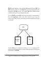
HOOD textual formalism is based on Object Description Skeletons (ODS). An
ODS should be defined for each Module that was defined during architectural
design phase. STOOD provides a full standard ODS plus additional sections
to include checking rules reports and generated code.
A set of STOOD extended ODS contains thus an exhaustive representation of
the overall Application, which, when fully completed, may become the
reference from which coherent production of both documentation and code may
be performed.
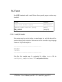
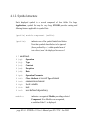
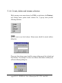
ODS
Documen
tation
Code
Extended ODS may be customized by editing DataBase configuration file,
and must be filled in with generic text editors. Following chapter describe how to
use text editors of STOOD.
page III-4 - STOOD v4.1 User’s Manual part III © TNI - Jan 2000
2. Text editors
2.1 Module selection list...................... p. 7
2.2 Section selection list.......................p. 8
2.3 Component selection list................ p.12
2.4 Text input area............................... p.14
2.5 Symbol table.................................. p.19
2.6 Window menu................................ p.24
2.7 Tools menu.....................................p.25
STOOD v4.1 User’s Manual part III © TNI - Jan 2000 - page III-5
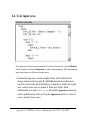
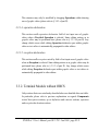
STOOD text editors are a set of generic browsers that are used to fill in or
visualize textual information related to an Application. This chapter describes
general contents and behaviour of text editors. To get further details about
precise contents and use of each editor, please refer to relevant chapter:
•
•
•
•
•
•
ods text editor
checks text editor
test text editor
ada text editor
c text editor
cpp text editor
refer to § 3
refer to part IV
refer to part IV
refer to part IV
refer to part IV
refer to part IV
These text editors are all defined and may be customized within DataBase
configuration file (refer to part I). Other specialized text editors may also be
created if needed. Each text editor is bound to a document editor from which a
printable document may be set up and produced. Please refer to § 5 for further
details about documentation production.
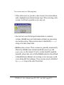
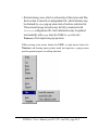
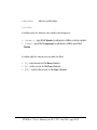
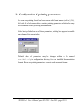
STOOD text editors are all composed of three selection lists, a text input area, a
symbol table for code sections and two menus, one of them being fully user
customizable. To open a text editor, use editors menu of main editor. Textual
edition is related to only one dedicated Module at a time. This Module should
be selected within top center list. As regard the kind of selected Module (refer
to part II to get more information about supported kinds of Modules), right list
is updated with appropriate sections. Some sections are global to current
Module, other are local to a Component belonging to current Module. In this
last case, relevant Component should be designated within top right list.
Finally current contents of selected section appear inside text input area, and
may be changed there (if not read only). Symbol table is updated when
accepting a code section.
page III-6 - STOOD v4.1 User’s Manual part III © TNI - Jan 2000
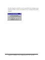
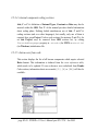
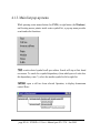
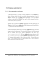
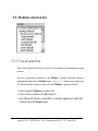
2.1. Module selection list
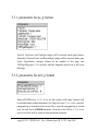
When an Application is selected in main editor, top center area of any text
editor displays the list of all known Modules for this Application. Modules
should have been created previously with graphic editor (refer to part II). There
is no way to create, delete nor rename a Module at this level.
Include relationship is represented by an additional indentation step in the list
of Modules. The list order is depth first, and at a given level, the oldest Module
first. This list cannot be reordered without deleting, creating or moving Modules
in a graphic editor.
STOOD v4.1 User’s Manual part III © TNI - Jan 2000 - page III-7
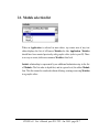
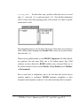
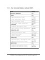
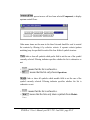
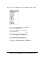
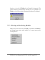
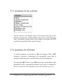
2.2. Section selection list
When a Module is selected in top center selection area, the list of relevant
textual sections is displayed within left area.
This list is differently configured for each text editor, and may also vary as
regards the kind of currently selected Module. In addition, some code sections
may be hidden by setting DiscardedLanguages property inside
.stoodrc file (for UNIX) or stood.ini file (for Windows).
page III-8 - STOOD v4.1 User’s Manual part III © TNI - Jan 2000
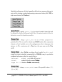
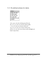
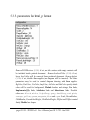
Text sections may be of following kinds:
• Titles which aim is to provide a clear structure for textual edition,
and to highlight main detailed design steps. When selecting a title
section, it will not be possible to save any text:
• Free text to be used for design documentation or comment
sections. STOOD stores such information without any processing
nor checking action. These sections may be identified by (text)
string at the end of their label.
• HOOD syntax sections. These sections are generally automatically
filled in by STOOD, from internal model that was set up with
graphic editor or other inputs. If such a section should be updated
manually, please take care to follow HOOD syntactic rules defined
in Hood Reference Manual, else warning or error messages could
occur during SIF file exchanges. These sections may be identified
by a (hood) string at the end of their label.
STOOD v4.1 User’s Manual part III © TNI - Jan 2000 - page III-9
• Target language code sections (Ada, C, C++, ...). These sections
may be filled in manually like free text ones. They may be left
empty to indicate to code generator to produce automatically
relevant code when possible (refer to part IV). When saving a
code section, its contents will be parsed by a dedicated lexical
analyser which result will be displayed within symbol table. These
sections may be identified by (ada), (c), (cpp) or (pseudo)
string at the end of their label. If one of these language was listed
in DiscardedLanguages property, relevant sections will be
hidden.
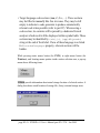
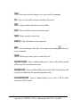
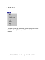
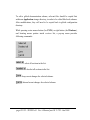
While pressing center mouse button (for UNIX), or right mouse button (for
Windows), and locating mouse pointer inside section selection area, a pop-up
menu shows following items:
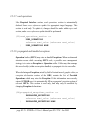
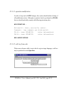
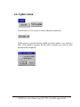
: provide information about actual storage location of selected section. A
dialog box shows actual location of storage file, if any (external storage area):
page III-10 - STOOD v4.1 User’s Manual part III © TNI - Jan 2000
If regarding information is deduced from internal model by a procedure,
following message is displayed (internal storage area):
: show the record from config/DataBase configuration file which
describes selected section (refer to part I).
STOOD v4.1 User’s Manual part III © TNI - Jan 2000 - page III-11
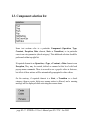
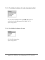
2.3. Component selection list
Some text sections refer to a particular Component (Operation, Type,
Constant, Exception, Data element, State or Transition), or in particular
cases to an extra parameter (check category). This additional selection should be
performed within top right list.
If required element is an Operation, a Type, a Constant, a Data element or an
Exception, They may be created, deleted or renamed at this level with local
pop-up menu commands. There is no need to use a graphic editor in that case,
but effect of these actions will be automatically propagated to other editors.
On the contrary, if required element is a State, a Transition or a check
category, then no create, delete nor rename action is allowed, and a warning
message will be displayed while activating these menu items.
page III-12 - STOOD v4.1 User’s Manual part III © TNI - Jan 2000
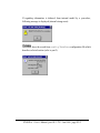
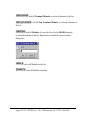
: add a new Component to the list, in a similar way to create actions in
graphic editor (refer to part II).
or
: remove selected Component from the list, in a similar way to delete
actions in graphic editor (refer to part II).
or
: rename selected Component in the list, in a similar way to rename
actions in graphic editor (refer to part II).
or
STOOD v4.1 User’s Manual part III © TNI - Jan 2000 - page III-13
2.4. Text input area
Text input area shows current contents of selected section for selected Module,
and if required, selected Component or other extra parameter. This information
may come from two different storage areas:
• Internal storage area, which roughly deals with architectural
design actions (refer to part II). STOOD internal procedures are
used to extract relevant information, to display it inside text input
area, and in some case to update it from user input. Such
information is stored in stood.dg file inside Application directory,
and is updated only when saving the Application with save item of
window menu of main editor.
page III-14 - STOOD v4.1 User’s Manual part III © TNI - Jan 2000
• External storage area, which is a hierarchy of directories and files.
Each section is bound to an independent file, which filename may
be obtained by where pop-up menu item of sections selection list.
This external storage structure may be fully customized with
DataBase configuration file. Such information may be updated
incrementally with accept item (for UNIX) or save item (for
Windows) of text input area pop-up menu.
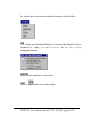
While pressing center mouse button (for UNIX), or right mouse button (for
Windows), and locating mouse pointer inside text input area, a pop-up menu
provides general purpose text editing functions:
STOOD v4.1 User’s Manual part III © TNI - Jan 2000 - page III-15
: Cancel previous text change or cut, paste or delete command.
: Copy to a text buffer and erase currently selected text.
: Copy currently selected text to a text buffer.
: Paste text buffer contents at insertion point.
: Erase currently selected text.
: Select all contents of text input area.
: Save text changes. Note that, in text input area, pushing
as save command.
button acts
: Restore previously saved version of the text.
: Open a standard dialog box to select a file which contents
will be pasted at current insertion point.
: Open a standard dialog box to select a file which location will
be used as a include link for some documentation tools.
: Open a standard dialog box to select a file in which
current text will be copied.
page III-16 - STOOD v4.1 User’s Manual part III © TNI - Jan 2000
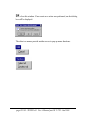
: provide contextual help regarding current textual edition. These help
files may not be all filled in. Anyway they may be customized by editing the
files contained in config/ods_help configuration directory.
: Provide a template current textual edition. Please refer to detailed
chapters related to each kind of graphical entity. These template files may be
customized by editing the files contained in config/ods_template
configuration directory (refer to part I of this User’s Manual).
STOOD v4.1 User’s Manual part III © TNI - Jan 2000 - page III-17
Note that changed text should be saved (or cancelled) before changing current
selection in modules, sections or secondary list. Else, a warning message will be
displayed:
page III-18 - STOOD v4.1 User’s Manual part III © TNI - Jan 2000
2.5. Symbol table
If selected section is a target language code section, entered text is supposed to
comply with lexical and syntactic rules of specified language (Ada, C, C++,
Pseudo code, or other). In order to properly manage code units dependencies,
STOOD performs source code analysis and displays results into a symbol
table, below text input area.
First step is a simple lexical analysis. There is an external lexical analyser for
each supported target language. They may easily be customized if required. To
perform this task, STOOD uses temporary files to communicate with lexical
analyser. These files are named tmp1 (input file) and tmp2 (output file) and are
created in the directory from which STOOD was launched. Please take care to
get write rights at this level. During this step, comments and language keywords
are withdrawn from symbols list. Composed notations may be recognized, like
some Ada dotted notations.
Second step consists in symbol identification. Each symbol or group of symbol
is compared to Application Modules and Components name, and a formatted
string is set up and displayed inside symbol table.
STOOD v4.1 User’s Manual part III © TNI - Jan 2000 - page III-19
Each symbol is structured as follow:
i_flag symb_kind mod_name.symb_name access_mode
ignore_flag
is a \ character and specifies that tagged symbol
must not be taken into account for dependency
analysis.
symbol_kind
is one of the following:
•
•
•
•
•
•
•
•
•
•
•
•
? undefined. Should be manually specified.
(op)
Operation
(ty)
Type
(co)
Constant
(ex)
Exception
(da)
Data
<pa>
Operation Parameter
<at>
Class Attribute or record Type element
<en>
enumeration element
<tp>
local variable
<ta>
task
<wi>
user defined dependency
module_name
is the name of one of known Module of current
Application, or ? if unrecognized.
symbol_name
is the name of found lexical element.
page III-20 - STOOD v4.1 User’s Manual part III © TNI - Jan 2000
access_mode
for data values only, specifies wether the access is in read
only [R], write only [W] or read write mode [RW]. Note that this information
will be correct only when parsing pseudo_code sections, for which a specific
syntax must be used:
This information may be used to draw data access charts from cross-references
tables. When another language than Pseudo Code is used, access_mode always
takes the value [R].
When a given symbol matches several HOOD Components, all valid solutions
are proposed, but only most likely one is left without ignore flag. Valid
solutions are those allowed by HOOD visibility rules, and most likely one is
the closest reference: local to current Module, sibling Modules, uncle Modules,
or Environments.
Due to some lack of information, and to the fact that only lexical and no
syntactic analysis is performed, STOOD automatic recognition is often
incomplete and sometimes erroneous. User's intervention may thus be required.
STOOD v4.1 User’s Manual part III © TNI - Jan 2000 - page III-21
Identified problems may be fixed manually with local pop-up menu that may be
activated by selecting a symbol and pressing center mouse button (for UNIX) or
right mouse button (for Windows):
: control ignore_flag for selected symbol. Same effect will
be obtained by double-clicking on symbol label. An ignored symbol will not be
taken into account for dependency analysis.
: change symbol_kind to one of those proposed in a
predefined list. This is useful to identify non-HOOD entities like enumeration
elements or local variables, or to solve ambiguousness due to homonyms (for
instance, in C++, constructors of a Class have the same name as the Class
itself).
: when Module providing selected symbol (module_name)
cannot be properly identified automatically by STOOD, it may be specified in
a dedicated sub-menu, with a few special choices:
<unknown> :
module_name field will be set to: ?
<none> :
symbol is local to current Module.
<type in...> to enter a Module name manually.
: change access_mode to one of the possible values: [R],
[W] or [RW].
page III-22 - STOOD v4.1 User’s Manual part III © TNI - Jan 2000
Each symbol table is stored at the same time and the same location as storage
file of selected section. They may be processed later by a cross references table
(refer to § 4), and in order to be able to manage properly code dependencies, no
unknown identifiers (?) should be left for not ignored symbols.
Update of a single symbol table is only feasible by saving code inside a text
input area, of a text editor, or an appropriate tab of a graphic editor (to
customize tabs of graphic editor, please refer to part I). Sometimes a global
update of several symbol tables may be required. Instead of accepting each
section individually, update symbol tables command of checkers menu in main
editor can be used to perform this task:
STOOD v4.1 User’s Manual part III © TNI - Jan 2000 - page III-23
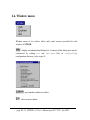
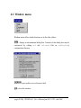
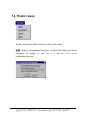
2.6. Window menu
Window menu of text editors offers only usual services provided for each
window of STOOD:
: display an informational dialog box. Contents of this dialog box may be
customized by editing txt and txt.more files in config/help
configuration directory (refer to part I).
: open another similar text editor.
: close current window.
page III-24 - STOOD v4.1 User’s Manual part III © TNI - Jan 2000
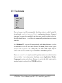
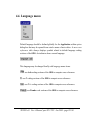
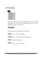
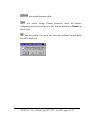
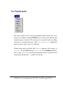
2.7. Tools menu
The tools menu is a fully customizable. Each item refers to a shell script file
located inside config/externalTools configuration directory. Proposed
items may be removed or modified, and others may easily be added to the list.
Each file should have a .sh suffix to be automatically included into tools menu
items list.
On a Windows PC, to get a full interoperability with Unix platforms, it is also
recommended to use an Unix shell emulator, like bash product from Cygnus
(http://www.cygnus.com). Doing this, the same shell scripts may be
written to be used in a similar way on an UNIX or a Windows platform.
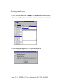
These externalTools may be useful to perform actions on selected section
of a text editor. A set of parameters identifying current Application, Module,
Component, section, and relevant filename, is sent to the shell script, and its
standard output is redirected to a STOOD dialog box.
STOOD v4.1 User’s Manual part III © TNI - Jan 2000 - page III-25
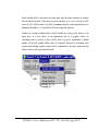
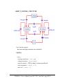
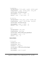
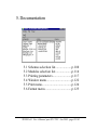
Following example shows:
• a text editor, in which a Module, a Constant and a section have
been selected and info item of tools menu has been activated.
• and corresponding result in output dialog box:
page III-26 - STOOD v4.1 User’s Manual part III © TNI - Jan 2000
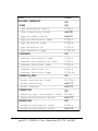
3. Object Description Skeleton
3.1 ODS Header................................... p.30
3.2 ODS Description............................ p.34
3.3 ODS Provided Interface................. p.47
3.4 ODS Required Interface................. p.57
3.5 ODS Internals.................................p.61
3.6 ODS Footer.................................... p.79
3.7 ODS Example.................................p.81
STOOD v4.1 User’s Manual part III © TNI - Jan 2000 - page III-27
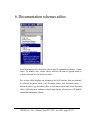
Hood Reference Manual defines a precise list of sections to be filled in for each
Module of an Application. This structured list is called Object Description
Skeleton. This chapter describes STOOD implementation of standard
HOOD4 ODS, and all extensions that was required for operational use and
automatic code generation. In addition, Real-Times attributes as defined by
HRT-HOOD have been introduced. When producing SIF files, extended
sections are propagated via dedicated Pragmas.
A standard ODS is composed of six main parts:
• a Header
• a Description part
• a Provided Interface part
• a Required Interface part
• an Internals part
• a Footer
ODS actual contents differ as regards the kind of corresponding Module. Please
refer to part II, § 3.2 to get more details about HOOD Modules kinds:
•
•
•
•
•
•
Terminal or Non Terminal Modules
Passive or Active Modules
Object or Class Modules
local or Environment Modules
Generic, Instance_Of or Op_Control Modules.
HRT-HOOD Cyclic, Sporadic or Protected Objects.
page III-28 - STOOD v4.1 User’s Manual part III © TNI - Jan 2000
STOOD ODS are customizable, and only default configuration is presented
here. If config/DataBase configuration file was customized by toolset
administrator (refer to part I), following explanations may be incomplete or
irrelevant.
ODS sections may be of following kinds:
•
•
•
•
•
structuring sections (titles)
textual informal descriptions (text)
HOOD syntactic sections (hood)
HRT-HOOD sections (hrt)
target language coding sections (ada, c or cpp)
ODS sections storage may be internal (automatically extracted from internal
model), in which case a procedure number is provided: auto(xx), or external in
which case a file pathname is provided (relative to SavePath property defined
in stood.ini or .stoodrc initialization file).
STOOD v4.1 User’s Manual part III © TNI - Jan 2000 - page III-29
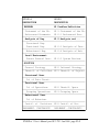
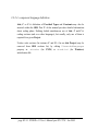
3.1. Header
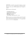
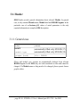
ODS Header provide general information about selected Module. In general
case, it only contains Module name, Module kind and HOOD Pragmas. In the
particular case of an Instance_Of, values of actual parameters is the only
required information to complete ODS description.
3.1.1. General case
section:
contents:
OBJECT
module type
automatically filled in by STOOD (17)
automatically filled in by STOOD (18)
pragma (hood)
file: PRAGMA
Object and module type sections are automatically deduced from relevant
HOOD diagram. In the ODS, they are both considered as titles and cannot be
changed. If a Module name or king needs to be changed, please operate from a
graphic editor.
page III-30 - STOOD v4.1 User’s Manual part III © TNI - Jan 2000
3.1.1.1. pragma
pragma section contains a list of HOOD directives that are usually managed
when preparing code generation. Refer to part IV to get further
information.These Pragmas may however be edited here, but take care to
comply with HOOD syntax. Else, code extractors initialization could fail and
produced SIF file could raise warning messages when imported back.
(73)pragma ::=
PRAGMA `pragma_`identifier
[pragma_parameter_part74] [";"]
(74)pragma_parameter_part ::=
"(" pragma_parameter75
{comma pragma_parameter75} ")"
(75)pragma_parameter ::=
`parameter_`identifier "=>"
pragma_parameter_value76
|
pragma_parameter_value76
(76) pragma_parameter_value ::=
op_reference
|
numeric_literal
|
free_text
STOOD v4.1 User’s Manual part III © TNI - Jan 2000 - page III-31
3.1.2. Instance_Of
section:
contents:
instance range (hood)
auto (16)
auto (17)
instance parameters (hood)
When selected Module is an Instance_Of Generic, actual parameters need to
be specified within instance parameters section. These parameters match formal
parameters of the Generic.
3.1.2.1. instance range
This section is only relevant for Instance_Of Modules and, if used, should
comply with following syntax:
(57)instance_range ::=
INSTANCE_RANGE integer "." "." integer
Note that STOOD does not manage multiple Instance_Of (so, this section is
useless for STOOD).
page III-32 - STOOD v4.1 User’s Manual part III © TNI - Jan 2000
3.1.2.2. instance parameters
(53)parameter_association_section ::=
TYPES
association54 {association 54}
| TYPES NONE
| CONSTANTS
association54 {association 54}
| CONSTANTS NONE
| OPERATIONS
association54 {association 54}
| OPERATIONS NONE
| OPERATIONS_SETS
association54 {association 54}
| OPERATIONS_SETS NONE
(54)association ::= identifier “=>” reference
Actual parameters are described in three categories (STOOD doesn’t manage
formal Operation Sets as described in the HOOD Reference Manual). For each
parameter of each category, a valid value should be specified. This value must be
a reference to a visible Component of the same kind, or a numeric value for
Constants.
For instance, if a Generic Module is a stack with a formal Type element,
each Instance_Of this stack must specify an actual value for element, that
should be another Type provided by any sibling, uncle or Environment
Module.
STOOD v4.1 User’s Manual part III © TNI - Jan 2000 - page III-33
3.2. Description
In first versions of HOOD (until v3.0) this part of the ODS was strongly
codified by the Hood Reference Manual. Since HRM 3.1, Description section
may be customized to best fit Projects requirements. A generic format was then
defined to be able to include relevant information within SIF files.
STOOD default implementation proposes a list of sections which keeps
general "spirit" of previous structure, but highlights new features of HOOD4,
like Classes and STDs.
For those who prefer using old style sections, a downwards compatibility
mapping is provided, and STOOD may easily be configured to follow this
requirements if needed.
page III-34 - STOOD v4.1 User’s Manual part III © TNI - Jan 2000
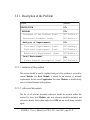
3.2.1. Description of the Problem
section:
contents:
DESCRIPTION
title
title
PROBLEM
Statement of the Problem (text)
DOC/StaPro.t
Referenced Documents (text)
DOC/RefDoc.t
Analysis of Requirements
title
Structural Requirements (text)
DOC/StrReq.t
Functional Requirements (text)
DOC/FunReq.t
Behavioural Requirements (text)
DOC/BehReq.t
Local Environment
title
Parent General Description (text) DOC/ParDes.t
3.2.1.1. statement of the problem
This section should be used to explain which part of the problem is covered by
current Module. For Root Module, it should be an abstract of informal
requirements for the overall Application. For other Modules, it should clearly
refer to a limited domain of the problem.
3.2.1.2. referenced documents
The list of all relevant document references should be inserted within this
section. For lower level Modules, only new references should be included, and
references already listed within higher level ODS are not worth being included
again.
STOOD v4.1 User’s Manual part III © TNI - Jan 2000 - page III-35
3.2.1.3. structural requirements
This section should extract relevant data structures for current Module, and
from requirement analysis phase. For instance, classes identified during Object
Oriented requirement analysis process (OMT or UML static models), could be
listed here, and will help identifying later HOOD Types and/or Classes.
3.2.1.4. functional requirements
From functional requirement analysis process (SADT, SA-RT, functional
models of Object Oriented methods), a list of relevant provided functional
services should be defined here for current Module.
3.2.1.5. behavioural requirements
This section should explain how previously identified services must interact to
provide required external behaviour of current Module. Part of dynamic models
from functional or Object Oriented requirement analysis process (SA-RT, UML
state transition or sequence diagrams) could be used to provide this information.
3.2.1.6. parent general description
Each description refer to a context. This section should be used to recall current
context. Within a HOOD hierarchy, context of a Module is a description of its
parent Module. For Root Module, this section could describe interactions with
Environment Modules. For other Modules, it could describe shortly
interactions with uncle Modules.
page III-36 - STOOD v4.1 User’s Manual part III © TNI - Jan 2000
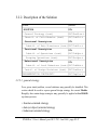
3.2.2. Description of the Solution
section:
SOLUTION
contents:
title
General Strategy (text)
DOC/GenStra.t
Identif. of Child Modules (text)
DOC/IdeChi.t
Structural Description
title
Identif. of Data Structures (text) DOC/IdeStr.t
Functional Description
title
Identif. of Operations (text)
DOC/IdeOpe.t
Grouping Operations (text)
DOC/GroOpe.t
Behavioural Description
title
Identif. of local Behaviour (text) DOC/IdeBeh.t
Justif. of Design Decisions (text) DOC/JusDes.t
IMPLEMENTATION CONSTRAINTS
DOC/ImpCon.t
3.2.2.1. general strategy
For a given stated problem, several solutions may generally be identified. This
section should be used to express general design strategy for current Module.
Roughly, three main design strategies may generally be applied within HOOD
top-down process:
• function oriented strategy
• data (or object) oriented strategy
• behaviour oriented strategy
STOOD v4.1 User’s Manual part III © TNI - Jan 2000 - page III-37
Each strategy often leads to a different solution. It is important to choose and
follow a well defined strategy, which should be explained and justified here.
3.2.2.2. child modules
If current Module has to be broken down, its child Modules should be listed
and shortly described here, as an introduction to their own ODS. Consistency
with graphical description should be ensured manually.
3.2.2.3. data structures
Main data structures of current Module should be described here, as part of
design solution. They may refer to structural requirements, or be pure solution
elements. Consistency with Types defined within current Module should be
ensured manually. When producing design documentation, type view of current
HOOD diagram will be inserted below this section.
3.2.2.4. operations
Main functional services of current Module should be described here, as part of
design solution. They may refer to functional requirements, or be pure solution
elements. Consistency with Operations defined within current Module should
be ensured manually. When producing design documentation, operation view of
current HOOD diagram will be inserted below this section.
page III-38 - STOOD v4.1 User’s Manual part III © TNI - Jan 2000
3.2.2.5. grouping operations
Grouping Operations into Operation Sets should follow logical rules that
must be explained within this section. Usual grouping rules are the following
ones:
• purely functional abstractions : same functional category
• related to a given data structure : OO member functions
• related to a given child Module : Operation dispatching
3.2.2.6. local behaviour
This section should contain an informal description of how previously identified
Operations must interact together with their environment to produce required
external behaviour. This could include information about Operations
receptivity as regards Module States, and communication protocols between
client and current Modules. Consistency with Operation constraints, States
and Transitions defined in HOOD diagrams and State Transition Diagrams
should be ensured manually. When producing design documentation, State
Transition Diagram (if any) will be inserted below this section.
3.2.2.7. design decisions
Previous sections were used to explain current design strategy and choices. This
section may be used to justify this solution as opposed to other possible
solutions for the same stated problem.
STOOD v4.1 User’s Manual part III © TNI - Jan 2000 - page III-39
3.2.2.8. implementation constraints
In some cases, design choices are not the result of a well followed strategy, but
are in fact part of initial requirements. For instance, Module breakdown may be
constrained by prescribed target architecture. Such constraints should be listed
here.
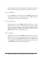
3.2.3. Compatibility with HOOD3.x
Following table shows the correspondence between STOOD v4 and HOOD3
Description sections. This information could be useful when importing a SIF
file from an older Application or another tool.
page III-40 - STOOD v4.1 User’s Manual part III © TNI - Jan 2000
STOOD v4
HOOD3
DESCRIPTION
DESCRIPTION
PROBLEM
H1 Problem Definition
Statement of the Pb.
H1.1 Statement of the Pb.
Referenced Documents
H1.2.1 Referenced Docs
Analysis of Req.
H1.2 Analysis and ...
Structural Req.
Functional Req.
H1.2.3 Analysis of Func.
Behavioural Req.
H1.2.4 Analysis of Beh.
Local Environment
Parent General Desc.
H1.2.2 System Environ.
SOLUTION
General Strategy
H2.2 Informal Strategy
Identif. of Child Mod. H3.1 Identif. of Objects
Structural Desc.
Id. of Data Struct.
Functional Desc.
Id. of Operations
H3.2 Identif. Opers
Grouping Operations
H3.3 Grouping Opers
Behavioural Desc.
Id. of Behaviour
Justif. of
Decisions
IMPLEMENT. CONSTRAINTS
H3.5 Justif. of Dec.
IMPLEMENT. CONSTRAINTS
STOOD v4.1 User’s Manual part III © TNI - Jan 2000 - page III-41
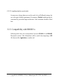
3.2.4. Real-Time Attributes (HRT_HOOD)
When selected Module is an HRT-HOOD Object, that it is a Cyclic,
Sporadic or Protected Object, additional information is required in the
Description part of the ODS. These additional fields are grouped into a
dedicated section called Real-Time Attributes.
These sections are organized as follow:
• Real-Time attributes for Protected Objects
• Real-Time attributes for Cyclic Objects
• Real-Time attributes for Sporadic Objects
• Thread Real-Time attributes for Cyclic and Sporadic Objects
• Operation Real-Time attributes for all HRT Objects
Please note that in HRT-HOOD standard definition, these attributes should be
defined for each operating mode of the Application. STOOD only supports a
unique set of Real-Time attributes, for now. In STOOD, the thread must be
explicitly defined as an Internal Operation named thread.
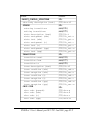
Next table shows the list of Real-Time attributes sections in STOOD ods text
editors. Of course, only relevant sections are displayed regarding the actual kind
of the selected Module.
A individual description is also provided for each section. Proposed
descriptions are directly issued from “HRT-HOOD: A Structured Design
Method for Hard Real-Time Ada Systems”, Alan Burns & Andy Wellings,
Elsevier editor. For further information, please refer to this book, as there is no
HRT-HOOD Reference Manual.
page III-42 - STOOD v4.1 User’s Manual part III © TNI - Jan 2000
section:
contents:
REAL_TIME_ATTRIBUTES
title
title
HRT Protected Attributes
Ceiling Priority (hrt)
HRT Cyclic Attributes
DOC/CeiPri.hrt
title
Period (hrt)
DOC/Period.hrt
Offset (hrt)
DOC/Offset.hrt
HRT Sporadic Attributes
title
Minimum Arrival Time (hrt)
DOC/MinTim.hrt
Maximum Arrival Frequency (hrt)
DOC/MaxFreq.hrt
HRT Thread Attributes
title
Deadline (hrt)
DOC/Ddline.hrt
Ceiling Priority (hrt)
DOC/CeiPri.hrt
Priority (hrt)
DOC/Priori.hrt
Precedence Constraints (hrt)
DOC/PreCon.hrt
Execution Time Transformation (hrt)
DOC/TimTra.hrt
Importance (hrt)
DOC/Import.hrt
operation declaration (hood)
title
auto(22)
Worst Case Execution Time (hrt)
OP/$Op_wcet.hrt
Budget Time (hrt)
OP/$Op_budg.hrt
OPERATION IS
END_OPERATION
title
STOOD v4.1 User’s Manual part III © TNI - Jan 2000 - page III-43
3.2.4.1. ceiling priority
Each Protected, Cyclic or Sporadic Object must have a defined ceiling
priority. This priority is no lower than the maximum priority of all the threads
that can call the constrained operations. A simple integer value should be
entered here.
3.2.4.2. period
Each Cyclic Object must have a defined period of execution. A simple integer
value should be entered here.
3.2.4.3. offset
Each Cyclic Object may have a defined offset which indicates the time that the
thread should delay before starting its cyclic operations. Each Sporadic Object
may also have a defined offset which indicates the time that the thread should
delay before starting each invocation. If used, a valid time duration value should
be entered here.
3.2.4.4. minimum arrival time & maximum arrival frequency
Each Sporadic Object must have either a defined minimum arrival time for
requests for its execution, and/or a maximum arrival frequency of request. For
each used section, an appropriate numeric value should be entered here.
3.2.4.5. deadline
Each Cyclic and Sporadic Object may have a defined deadline for the execution
of its thread. An appropriate numeric value should be entered here.
page III-44 - STOOD v4.1 User’s Manual part III © TNI - Jan 2000
3.2.4.6. priority
Each Cyclic and Sporadic Object must have a defined priority for its thread.
This priority is defined according to the scheduling theory being used (for
instance, according to the thread’s period or its deadline). A simple integer value
should be entered here, or automatically inserted by an appropriate
schedulability analysis tool.
3.2.4.7. precedence constraints
A thread may have precedence constraints associated with its execution. This
attribute indicates which Object must execute before and after it.
3.2.4.8. execution time transformation
A Cyclic or Sporadic Object may need to be transformed at run-time to
incorporate extra delays. This may be required, for example, as a result of period
transformation during the schedulability analysis phase of the method.
3.2.4.9. importance
Each Cyclic or a Sporadic Object must have a defined importance. This
importance represents whether the Object is a Hard Real-Time thread or a Soft
Real-Time Object. Typical possible values are:
importance := HARD | SOFT | BACKGROUND
STOOD v4.1 User’s Manual part III © TNI - Jan 2000 - page III-45
3.2.4.10. worst case execution time
Each Cyclic and Sporadic Object may have a worst case execution time
(WCET) defined for its thread of execution. In STOOD the thread is a
dedicated Internal Operation which needs to be created with the reserved
name thread. The worst case execution time for the thread is the thread’s
budget time plus the budget time of the internal error handling operation. If a
thread overruns its WCET then it is terminated for the current invocation. An
appropriate time duration value should be entered here.
3.2.4.11. budget time
Each Cyclic and Sporadic Object may have a budget execution time defined for
each activation of its thread of execution. An overrun of the budgeted time
results in the termination of the activity being undertaken. Each Cyclic and
Sporadic Object may have an Internal Operation which is to be called if its
thread’s budget execution time is violated. An appropriate time duration value
should be entered here.
page III-46 - STOOD v4.1 User’s Manual part III © TNI - Jan 2000
3.3. Provided Interface
Provided Interface sections should be used to add textual information related to
Components that were created during architectural design phase while adding
an element within interface box of a Module, or from top right list pop up menu
(refer to § 2.3).
Operations, Exceptions, and Operations Sets declarative parts may be fully
described within graphic editor textual area. HOOD general rules consider that a
Provided Constant value is part of the Internals, and in the case of structured
Types, their declarative part may be deduced from architectural design
information (super Classes, Attributes). Provided Interface sections are thus
strongly independent from target language code syntax.
Practically, some Types definitions and Constants definitions need to be
expressed within Provided Interface part of the ODS for Terminal Modules,
and should comply with target language syntax to be inserted into generated
code.
Provided Interface sections may thus contain:
• textual information related to each Provided Component (text).
• target language sections for Types or Constants (lang).
• HOOD syntax sections for Types, Operations, Exceptions (hood).
lang denotes here one of the suuported target languages: ada, c or cpp
STOOD v4.1 User’s Manual part III © TNI - Jan 2000 - page III-47
Provided Interface part of the ODS differs as regards the kind of current
Module. Following cases are described in detail below:
• Non Terminal Modules without OBCS
• Terminal Modules without OBCS
• Provided OBCS
• other kinds of Modules
page III-48 - STOOD v4.1 User’s Manual part III © TNI - Jan 2000
3.3.1. Non Terminal Modules without OBCS
section:
contents:
PROVIDED INTERFACE
title
title
TYPES
type description (text)
T/$Tp.t
class inheritance (hood)
auto(30)
auto(31)
auto(42)
title
type attributes (hood)
child type (lang) definition
CONSTANTS
constant description (text)
C/$Cp.t
child constant (lang) definition
auto(43)
title
OPERATION_SETS
op-set description (text)
OPS/$Os.t
op-set definition
auto (37)
auto (81)
title
op-set contents
OPERATIONS
operation spec. description (text) OP/$Op.t
operation declaration (hood)
EXCEPTIONS
auto (22)
title
exception description (text)
X/$Ex.t
exception declaration (hood)
auto (32)
STOOD v4.1 User’s Manual part III © TNI - Jan 2000 - page III-49
3.3.1.1. component description sections
Each Provided Component (Type, Constant, Operation, Exception) or
Operation Set may be described at this level, within relevant textual section.
This information is stored in an independent file for each Component. This text
may be used to be later included inside design documentation and as an option,
to comment generated code.
These informal sections should not be neglected, as they provide a very efficient
way to document the Application step by step, and not to postpone globally
this task at the end of detailed design phase.
3.3.1.2. child sections
Components declared within Provided Interface of Non Terminal Modules
do not locally include any implementation. They refer to lower level Modules
which actually contain relevant implementation.
It is anyway often convenient to get a direct access to final implementation of
selected Component of a Non Terminal Module. STOOD provide such a
feature to avoid browsing the ODS. These child sections are actually simple
logical links to relevant Terminal Module information, if any.
3.3.1.3. op-set definition and contents
These two sections show information that may only be updated within text
input area of graphic editor, when an Operation Set is selected. In HOOD
syntax, op-set definition contains nothing but Operation Set name itself. To
change it, please simply rename the Operation Set. op-set contents shows a
textual representation of Set structure.
page III-50 - STOOD v4.1 User’s Manual part III © TNI - Jan 2000
This structure may only be modified by dragging Operations within drawing
area of graphic editor (please refer to § 3.4.3 of part II).
3.3.1.4. operation declaration
This section recalls operation declaration field of text input area of graphic
editor when a Provided Operation is selected. Same editing actions as in
graphic editor may be performed here (please refer to § 3.3.3 of part II). Any
change which occurs while editing Operation declarative part within graphic
editor or text editors is automatically propagated to other editors.
3.3.1.5. exception declaration
This section recalls exception raised by field of text input area of graphic editor
when an Exception is selected. Same editing actions as in graphic editor may be
performed here (please refer to § 3.5.3 of part II). Any change which occurs
while editing Exception declarative part within graphic editor or text editors is
automatically propagated to other editors.
3.3.2. Terminal Module without OBCS
Only sections that were not already described above are detailed after next table.
In particular, please refer to previous explanations as regards Components
textual description sections, op-set definition and contents sections, operation
and exception declaration sections
STOOD v4.1 User’s Manual part III © TNI - Jan 2000 - page III-51
section:
PROVIDED INTERFACE
TYPES
type description (text)
class inheritance (hood)
type attributes (hood)
type pre-declaration (ada)
contents:
title
title
T/$Tp.t
auto(30)
auto(31)
T/$Tp.s
type definition (ada)
type definition (c)
type definition (cpp)
CONSTANTS
T/$Tp.u
T/$Tp.h
T/$Tp.hh
constant description (text)
constant pre-declaration (ada)
constant definition (ada)
constant definition (c)
constant definition (cpp)
OPERATION_SETS
C/$Cp.t
C/$Cp.s
C/$Cp.u
C/$Cp.h
C/$Cp.hh
op-set description (text)
op-set definition
op-set contents
OPERATIONS
title
title
OPS/$Os.t
auto (37)
auto (81)
title
operation spec. description (text) OP/$Op.t
operation declaration (hood)
auto (22)
EXCEPTIONS
title
exception description (text)
exception declaration (hood)
X/$Ex.t
auto (32)
page III-52 - STOOD v4.1 User’s Manual part III © TNI - Jan 2000
3.3.2.1. class inheritance
This section recalls class inheritance field of text input area of graphic editor
when a Provided Type is selected. Same editing actions as in graphic editor may
be performed here (please refer to § 3.7.3 of part II). Any change which occurs
while editing Type declarative part within graphic editor or text editors is
automatically propagated to other editors.
3.3.2.2. type attributes
This section recalls type attributes field of text input area of graphic editor when
a Provided Type is selected. Same editing actions as in graphic editor may be
performed here (please refer to § 3.7.3 of part II). Any change which occurs
while editing Type declarative part within graphic editor or text editors is
automatically propagated to other editors.
3.3.2.3. type and constant ada pre-declaration
In the particular case when target language is Ada, and use of private types or
deferred constants is required, these two sections may be used to insert Type or
Constant pre-declarations that will be included inside public part of relevant
package specification.
If these sections remain empty, relevant Types and Constants full declaration
will be inserted inside public part of package specification. If they contain predeclarations, full declarations will be inserted inside private part of package
specification. Please refer to part IV to get further details.
STOOD v4.1 User’s Manual part III © TNI - Jan 2000 - page III-53
3.3.2.4. component language definition
Ada, C or C++ definition of Provided Types and Constants may also be
inserted within the ODS. Part IV of this manual provides detailed information
about coding phase. Nothing forbids simultaneous use of Ada, C and C++
coding sections (and even other languages), but usually, only one of them is
required for a given Project.
Useless code sections (for instance C and C++ for an Ada Project) may be
removed from ODS sections list, by editing DiscardedLanguages
property in .stoodrc (for UNIX) or stood.ini (for Windows)
initialization file.
page III-54 - STOOD v4.1 User’s Manual part III © TNI - Jan 2000
3.3.3. Provided OBCS
Provided Interface of a Terminal or Non Terminal Module that contains
Constrained Operations, will be described by an extended ODS, showing
following additional section:
section:
OBJECT_CONTROL_STRUCTURE
contents:
title
obcs spec. description (text)
STD/obcs.t
constrained operations
auto (34)
3.3.3.1. obcs specifications description
OBject Control Structure of a Module providing Constrained Operations
may be documented within relevant ODS. OBCS documentation is split into
two parts: obcs spec. description which should explain external behaviour, and
obcs body description to describe how this behaviour is implemented. This latter
section will be found in the Internals.
3.3.3.2. constrained operations
This section recalls trigger label field of text input area of graphic editor when
an Operation is selected. Same editing actions as in graphic editor may be
performed here (please refer to § 3.3.3 of part II). Any change which occurs
while editing Operation declarative part within graphic editor or text editors is
automatically propagated to other editors.
STOOD v4.1 User’s Manual part III © TNI - Jan 2000 - page III-55
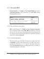
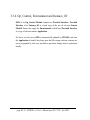
3.3.4. Op_Control, Environment and Instance_Of
ODS of an Op_Control Module contains no Provided Interface. Provided
Interface of an Instance_Of is a local copy of the one of relevant Generic
Module. Same rules apply for Environments, which local Provided Interface
is a copy of relevant remote Application.
For these two last cases, ODS is automatically updated by STOOD each time
the Application is loaded, but please note that file storage sections contents are
never propagated by this way, and that no persistent change may be performed
locally.
page III-56 - STOOD v4.1 User’s Manual part III © TNI - Jan 2000
3.4. Required Interface and Flows
Required Interface is supposed to provide an exhaustive list of all remote
Components that are used locally. This list should be structured as follow:
(15)required_interface_section ::=
REQUIRED_INTERFACE
required_object16 {required_object16}
|
REQUIRED_INTERFACE NONE
(16)required_object ::=
required_object_header17 semi_colon
required_entity_section18
{required_entity_section 18}
|
required_object_header17 semi_colon NONE
(17)required_object_header ::=
OBJECT `object_`identifier
|
FORMAL_PARAMETERS
(18)required_entity_section ::=
TYPES {pragma}
reference semi_colon {reference semi_colon}
|
TYPES {pragma} NONE
|
CONSTANTS {pragma}
reference semi_colon {reference semi_colon}
|
CONSTANTS {pragma} NONE
|
OPERATIONS {pragma}
reference semi_colon {reference semi_colon}
|
OPERATIONS {pragma} NONE
STOOD v4.1 User’s Manual part III © TNI - Jan 2000 - page III-57
|
|
|
|
OPERATION_SETS {pragma}
reference semi_colon {reference semi_colon}
OPERATION_SETS {pragma} NONE
EXCEPTIONS {pragma}
reference semi_colon {reference semi_colon}
EXCEPTIONS {pragma} NONE
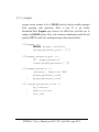
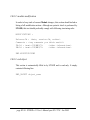
This information do not need to be inserted manually. STOOD may
automatically update this field from cross references editor. When any change
invalidates cross references, following message is displayed within required
interface section:
--{ cross references are out of date }-NONE
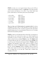
Cross references are related to a given target language (Ada, C , C++, or
Pseudo). Please, take care to set correct default language (option item of window
menu of main editor), in order to get appropriate Required Interface.
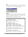
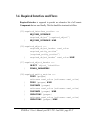
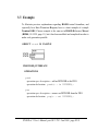
To update Required Interface section of an ODS, open a cross references
editor, check current language and press update button. See below an example of
an updated Required Interface for a Module which requires:
• Type instruments.Acc
• Operations instruments.Set_Name,
•
instruments.Display_Values
• Operations io.Put, io.Get, io.Put_Line, io.New_Line
page III-58 - STOOD v4.1 User’s Manual part III © TNI - Jan 2000
OBJECT instruments;
TYPES
Acc;
CONSTANTS
NONE
OPERATION_SETS
NONE
OPERATIONS
Set_Name; Display_Value;
EXCEPTIONS
NONE
OBJECT io;
TYPES
NONE
CONSTANTS
NONE
OPERATION_SETS
NONE
OPERATIONS
Get; Put; Put_Line; New_Line;
EXCEPTIONS
NONE
STOOD v4.1 User’s Manual part III © TNI - Jan 2000 - page III-59
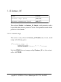
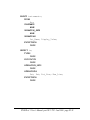
In addition to the Required Interface itself, this part of the ODS also recalls
all DataFlows and Exception Flows related to current Module, and that was
defined within drawing area of graphic editor:
section:
REQUIRED_INTERFACE
DATAFLOWS
EXCEPTION_FLOWS
contents:
auto(36)
auto(4)
auto(5)
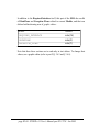
Note that these three sections are in read-only in text editors. To change their
values, use a graphic editor (refer to part II, § 3.6.5 and § 3.6.6).
page III-60 - STOOD v4.1 User’s Manual part III © TNI - Jan 2000
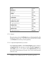
3.5. Internals
Internal sections should be used to add textual information related to
Components that were created either by adding graphically an element within
body box of a Terminal Module, either from top right list pop up menu of a
text editor (refer to § 2.3).
Like Provided ones, Internal Operations declarative parts may be fully
described within graphic editor textual area. HOOD general rules consider that
there should be no Internal Exceptions nor Sets. On the contrary, Internal
Data are allowed whereas they are forbidden inside Provided Interface. In
addition, Internals is the place where all Operation and OBCS bodies should
be included.
Internal sections may thus contain:
• textual information related to each Internal Component (text).
• target language declaration sections for Types, Constants or Data
(ada, c or cpp).
• HOOD syntax sections for Operations (hood).
• target language body sections for OPCS or OBCS (ada, c, cpp or
pseudo).
STOOD v4.1 User’s Manual part III © TNI - Jan 2000 - page III-61
Internal part of the ODS differs as regards the kind of current Module.
Following cases are described below:
Non Terminal Modules without OBCS
OBCS of Non Terminal Modules
Terminal Modules without OBCS
OBCS of Non Terminal Modules
• other kinds of Modules
•
•
•
•
3.5.1. Non Terminal Module without OBCS
When a Module is Non Terminal, its Internals contains only other Modules.
Relevant ODS simply recalls information already provided by HOOD
diagrams. There is no way to insert or modify thes informations directly with an
ods text editor:
Next table describes the ODS sections that appear when a Non Terminal
Module without any constrained Operations is selected:
page III-62 - STOOD v4.1 User’s Manual part III © TNI - Jan 2000
section:
contents:
INTERNALS
title
auto(1)
title
auto(62)
title
auto(63)
title
auto(66)
title
auto(61)
title
auto(64)
OBJECTS
TYPES
implemented_by
CONSTANTS
implemented_by
OPERATION_SETS
implemented_by
OPERATIONS
implemented_by
EXCEPTIONS
implemented_by
3.5.1.1. objects
This section shows a list of child Modules that were defined graphically within
drawing area of graphic editor. This textual section is read-only and any change
to child Modules list should be performed graphically.
3.5.1.2. component implemented_by sections
Each Component Provided by a Non Terminal Module should be attached to
an Implemented By link connecting it to another Provided Component of a
child Module (refer to § 3.10 of part II). These Implemented By links may
only be edited within drawing area of graphic editor, but are textually presented
within this section.
STOOD v4.1 User’s Manual part III © TNI - Jan 2000 - page III-63
3.5.2. OBCS of a Non Terminal Module
When a Non Terminal Module provides at least one Constrained
Operation, its behaviour may be described textually within Internals part of
the ODS. Actual implementation of this behaviour will be found inside
Terminal Modules implementing Constrained Operations.
section:
OBJECT_CONTROL_STRUCTURE
contents:
title
obcs body description (text)
STD/obcs.t2
implemented_by
auto(35)
3.5.2.1. obcs body description
This section may contain a textual and informal description of required
behaviour for selected Non Terminal Module. Consistency with actual
implementation within relevant child Modules should be ensured manually.
3.5.2.2. obcs implemented_by
This section recalls which child Modules actually implement behaviour of
current Non Terminal Module. This information is automatically deduced
from graphic edition, and no change is allowed at this level.
page III-64 - STOOD v4.1 User’s Manual part III © TNI - Jan 2000
Please note that there is no formal Implemented By link for State Transition
Diagrams. There is no general rules to automatically ensure consistency between
a high level STD and child STDs. This is particularly true for States: if
modular breakdown was not performed to dispatch known States of a parent
STD into child Modules, there will be no easy one to one mapping between
parent and child States. On the contrary, Transitions are directly linked to
Constrained Operations for which a one to one Implemented By link should
be defined.
3.5.3. Terminal Module without OBCS
Internals ODS of Terminal Modules should contain all textual information
that misses to complete design documentation and code generation. It contains
sections to document and code Internal Components, and bodies of all
Operations (Provided and Internal) and of the OBCS, if any.
Following table describes the ODS sections that are displayed when a
Terminal Module without any constrained Operations is selected:
STOOD v4.1 User’s Manual part III © TNI - Jan 2000 - page III-65
section:
contents:
INTERNALS
title
title
TYPES
type description (text)
T/$Tp.t
type attributes (hood)
auto(31)
type definition (ada)
T/$Tp.u
type definition (c)
T/$Tp.h
type definition (cpp)
T/$Tp.hh
CONSTANTS
title
constant description (text)
C/$Cp.t
constant definition (ada)
C/$Cp.u
constant definition (c)
C/$Cp.h
constant definition (cpp)
C/$Cp.hh
OPERATIONS
title
operation spec. description (text) OP/$Op.t
operation declaration (hood)
DATA
auto(22)
title
data description (text)
D/$Da.t
data declaration (ada)
D/$Da.s
data declaration (c)
D/$Da.c
data declaration (cpp)
D/$Da.cc
data access from code
auto(91)
page III-66 - STOOD v4.1 User’s Manual part III © TNI - Jan 2000
3.5.3.1. internal component description sections
Each Internal Component (Type, Constant, Operation, Data) may be
described at this level, within relevant textual section. This information is stored
in an independent file for each Component. This text may be used to be later
included inside design documentation and as an option, to comment generated
code.
These informal sections should not be neglected, as they provide a very efficient
way to document the Application step by step, and not to postpone globally
this task at the end of detailed design phase.
3.5.3.2. internal type attributes
This section recalls type attributes field of text input area of graphic editor when
an Internal Type is selected. Same editing actions as in graphic editor may be
performed here (please refer to § 3.7.3 of part II). Any change which occurs
while editing Type declarative part within graphic editor or text editors is
automatically propagated to other editors.
3.5.3.3. internal operation declaration
This section recalls operation declaration field of text input area of graphic
editor when an Internal Operation is selected. Same editing actions as in
graphic editor may be performed here (please refer to § 3.3.3 of part II). Any
change which occurs while editing Operation declarative part within graphic
editor or text editors is automatically propagated to other editors.
STOOD v4.1 User’s Manual part III © TNI - Jan 2000 - page III-67
3.5.3.4. internal component coding sections
Ada, C or C++ definition of Internal Types, Constants or Data may also be
inserted within the ODS. Part IV of this manual provides detailed information
about coding phase. Nothing forbids simultaneous use of Ada, C and C++
coding sections (and even other languages), but usually, only one of them is
required for a given Project. Useless code sections (for instance C and C++ for
an Ada Project) may be removed from ODS sections list, by editing
DiscardedLanguages property in .stoodrc (for UNIX) or stood.ini
(for Windows) initialization file.
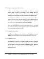
3.5.3.5. data access from code
This section displays the list of all known components which require selected
Data element. This information is deduced from the cross references table,
which needs to be updated. If cross references were calculated from Pseudo
Code sections, information about access mode ([R], [W] or [RW]) will also be
available:
page III-68 - STOOD v4.1 User’s Manual part III © TNI - Jan 2000
section:
OPERATION_CONTROL_STRUCTURE
OPERATION_IS
contents:
title
auto(20)
operation body description (text) OP/$OP.t2
propagated exceptions
auto(23)
auto(33)
handled exceptions (hood)
OP/$OP.hx
operation declaration (hood)
auto(22)
operation code extension (ada)
OP/$OP.x
operation code (pseudo)
OP/$OP.p
operation code (ada)
OP/$OP.u
operation code (c)
OP/$OP.c
operation code (cpp)
OP/$OP.cc
call tree from code
auto(94)
operation modifications (hood)
OP/$OP_modif
used operations
END_OPERATION
auto(21)
3.5.3.6. operation body description
Each Provided or Internal Operation of a Terminal Module has an
OPeration Control Structure part in the ODS. This OPCS should be used to
document and code body of each Operation. This particular section should be
used to provide textual information on actual contents of selected OPCS. Please
note that there are two operation description sections for each Operation of a
Terminal Module. One of them is supposed to document it externally, and the
other internally.
STOOD v4.1 User’s Manual part III © TNI - Jan 2000 - page III-69
3.5.3.7. used operations
Like Required Interface section, used operations section is automatically
deduced from cross references update for appropriate target language. This
section is read only. To update it, changes should be made within opcs code
section, and a cross references update should be performed.
(33)used_operations_section ::=
USED_OPERATIONS
reference semi_colon {reference semi_colon}
|
USED_OPERATIONS NONE
3.5.3.8. propagated and handled exceptions
Operation bodies (OPCS) may raise or handle Exceptions. When an abnormal
situation occurs while executing OPCS code, a possible error management
strategy is to raise an Exception to Operation caller. Caller may thus manage
this error locally (within an exception handler) or propagate it to its own caller.
When declaring an Exception, raised by field of textual area of graphic editor, or
exception declaration section of the ODS, contain the list of Provided
Operations which may raise the Exception. If this information was correctly
entered, STOOD uses it to automatically fill in propagated exception section of
relevant OPCSs. This section is read only, and may only be modified by
changing Exception declarations:
(34)propagated_exceptions_section ::=
PROPAGATED_EXCEPTIONS
reference semi_colon {reference semi_colon}
|
PROPAGATED_EXCEPTIONS NONE
page III-70 - STOOD v4.1 User’s Manual part III © TNI - Jan 2000
On the contrary, as STOOD code analysers are purely lexical and not
syntactic, there is no easy way to automatically deduce which Exceptions are
actually handled by a given Operation body. This information should be
entered manually within handled exceptions section of the ODS. Note that
HOOD syntax should be used in order to ensure correct Standard Interchange
Format input or output. STOOD does not provide any syntactic verification
while filling in this section.
(35)handled_exceptions_section ::=
HANDLED_EXCEPTIONS
reference semi_colon {reference semi_colon}
|
HANDLED_EXCEPTIONS NONE
3.5.3.9. operation code extension
For Ada coding of Operations, this section may be used optionally to insert an
extra piece of code just after the declarative part. Typical use of such a feature is
to insert an Ada pragma:
-- Ada 83:
pragma INTERFACE(C, op_name);
-- Ada95:
pragma IMPORT(C,op_name,"C_function");
When this section is filled in, no code will be produced for relevant Operation
body during Ada code generation.
STOOD v4.1 User’s Manual part III © TNI - Jan 2000 - page III-71
3.5.3.10. opcs code sections
Pseudo code, Ada, C or C++ code for each OPCS (Operation body) may also
be inserted within the ODS. Part IV of this manual provides detailed
information about coding phase. Nothing forbids simultaneous use of Pseudo
code, Ada, C and C++ coding sections (and even other languages), but usually,
only one of them is required for a given Project. Useless code sections (for
instance C and C++ for an Ada Project) may be removed from ODS sections
list, by editing DiscardedLanguages property in .stoodrc (for UNIX) or
stood.ini (for Windows) initialization file.
Pseudo code is not formally defined by HOOD. In STOOD, it follows same
lexical rules as Ada, except that an additional comment syntax may be used to
insert incomplete or syntactically incorrect code. Pseudo code sections may be
used to fill in the cross references table without entering all relevant target
language code. Following example shows Pseudo code that could be used to
update used operations section:
[functional dependencies at code level]
motor1.start
motor2.start
In addition, access to Data may be analysed more precisely with Pseudo code.
Reading or writing Data will be identified if := or = operators are used.
Operation Parameters passing mode (in, out or in out) is also analysed in
this case. Result of this analysis is stored in symbol tables ([R], [W] and
[RW]), and is used to display data access from pseudo code section (§ 3.5.3.5),
and display data access charts.
page III-72 - STOOD v4.1 User’s Manual part III © TNI - Jan 2000
3.5.3.11. operation modification
In order to keep track of OPCS changes, this section should include a listing of
all modification actions. Although no syntactic check is performed by STOOD,
this text should preferably comply with following structuring rules:
MODIFICATIONS :
Release-Id : <date, version-Id, author>
Comments : <any comments you think useful>
FA-Id : <num> <DD\MM\YY>
<other informations>
DM-Id : <num> <DD\MM\YY>
<other informations>
END MODIFICATIONS
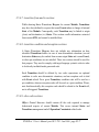
3.5.3.12. call tree from code
When cross references table is up to date for a given target language, a call tree
may be produced for each Operation:
STOOD v4.1 User’s Manual part III © TNI - Jan 2000 - page III-73
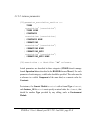
3.5.4. Internal OBCS of Terminal Module
When a Terminal Module provides Constrained Operations, additional
Internal sections should be filled in to document and code its OBCS:
3.5.4.1. obcs body description
In the same way as for Operations, an OBCS need to be described twice. Once
externally within Provided Interface to explain external behaviour of current
Module, and once internally within the Internals, to explain how this
behaviour is actually implemented.
3.5.4.2. state description
States Transitions Diagram may have identified several States for current
Module. This section should be used to document individually each of them.
3.5.4.3. state entering and exiting transitions
While drawing States Transitions Diagram for current Module, Transitions
may have been defined to express that some Events induce a change of internal
State of the Module. Consequently, each State may be linked to entering and
exiting Transitions. This section only recalls information extracted from current
STD, and cannot be modified here.
page III-74 - STOOD v4.1 User’s Manual part III © TNI - Jan 2000
section:
OBJECT_CONTROL_STRUCTURE
obcs body description (text)
STATES
entering transitions
exiting transitions
state description (text)
state assignment (ada)
state test (ada)
state assignment (c)
state test (c)
state assignment (cpp)
state test (cpp)
TRANSITIONS
transition event
transition from
transition to
trans description (text)
trans condition (ada)
trans exception (ada)
trans condition (c)
trans exception (c)
trans condition (cpp)
trans exception (cpp)
OBCS CODE
obcs code (pseudo)
obcs code (ada)
obcs code (c)
obcs code (cpp)
contents:
title
STD/obcs.t2
title
auto(226)
auto(225)
STD/$Se.t
STD/$Se_set.u
STD/$Se_get.u
STD/$Se_set.c
STD/$Se_get.c
STD/$Se_set.cc
STD/$Se_get.cc
title
auto(224)
auto(227)
auto(228)
STD/$Se.t2
STD/$Se_cnd.u
STD/$Se_exc.u
STD/$Se_cnd.c
STD/$Se_exc.c
STD/$Se_cnd.cc
STD/$Se_exc.cc
title
STD/obcs.p
STD/obcs.u
STD/obcs.c
STD/obcs.cc
STOOD v4.1 User’s Manual part III © TNI - Jan 2000 - page III-75
3.5.4.4. state assignment and test sections
A States Transitions Diagram does not include any information on how
identified States are related to actual Data of current Module. These two
sections should be used for that purpose. They need to comply with target
language syntactic rules in order to be directly included inside generated code.
Each State should be defined by two code expressions: an assignment of state
variables, and a test of these same state variables. For a given State, testing code
will be used as a pre-condition for an exiting Transition, whereas assignment
code will be used as a post-condition for an entering Transition.
Please, note that STOOD does not perform any semantic check to ensure that
only valid state variables are used, neither that assigned values actually match
corresponding State identified in the STD.
3.5.4.5. transition description
States Transitions Diagram may have identified several Transitions for current
Module. This section should be used to document individually each of them.
3.5.4.6. transition event
Each Transition is triggered by an Event. In HOOD design model, an Event
must be raised by a call of one of the Provided Operations of current Module.
This information is entered while designing a Transition in States Transitions
Diagram. This section recalls this information within the ODS, but cannot be
modified at this level.
page III-76 - STOOD v4.1 User’s Manual part III © TNI - Jan 2000
3.5.4.7. transition from and to sections
While drawing States Transitions Diagram for current Module, Transitions
may have been defined to express that some Events induce a change of internal
State of the Module. Consequently, each Transition may be linked to origin
(from) and destination (to) States. This section recalls information extracted
from current STD, and cannot be modified here.
3.5.4.8. transition condition and exception sections
A States Transitions Diagram does not include any information on how
identified Transitions behave in case of non deterministic situations (several
destination States may be reached from a same origin State and a same Event),
or when pre-conditions are not satisfied. These two sections should be used for
that purpose. They need to comply with target language syntactic rules in order
to be directly included inside generated code.
Each Transition should be defined by two code expressions: an optional
condition to solve non deterministic situations, and an exception code to deal
with Event refusal. For a given Transition, condition code will be used as a
pre-condition, whereas exception code will be used as a post-condition. Please,
note that theoretically, this exception code should be related to the Event itself,
not to all triggered Transitions.
3.5.4.9. obcs code sections
OBject Control Structure should contain all the code required to manage
behavioural aspects of current Module. This covers internal States and
Transitions management and all Operation Constraints related code.
STOOD v4.1 User’s Manual part III © TNI - Jan 2000 - page III-77
Ideal solution is to define code generation rules in order to automatically
produce OBCS code from design information (State Transition Diagram,
Operation Constraints). A large number of behavioural mapping rules have
been defined for Ada (tasking, protected types), and for C (calling Real-Time
Operating Systems primitives).
STOOD code generators may easily be enhanced to take into account specific
coding environments (Real Time Operating Systems, libraries), but when these
improvements cannot be undertaken, OBCS code may have to be inserted
manually within obcs code sections of the ODS.
Pseudo code, Ada, C or C++ code for OBCS may thus be inserted within the
ODS. Part IV of this manual provides detailed information about coding phase.
Nothing forbids simultaneous use of Pseudo code, Ada, C and C++ coding
sections (and even other languages), but usually, only one of them is required for
a given Project. Useless code sections (for instance C and C++ for an Ada
Project) may be removed from ODS sections list, by editing
DiscardedLanguages property in .stoodrc (for UNIX) or stood.ini
(for Windows) initialization file.
As for opcs code (refer to § 3.5.3.10), Pseudo code sections may be used to fill
in the cross references table without entering all relevant target language code.
3.5.5. Op_Control, Environment and Instance_Of
Environment and Instance_Of Modules have no Internal ODS, and
Op_Control Internal ODS contains only appropriate OPCS.
page III-78 - STOOD v4.1 User’s Manual part III © TNI - Jan 2000
3.6. Footer
Each ODS terminates with a small footer where general purpose sections may
be added.
section:
contents:
code file header (text)
DOC/header
module modifications (hood)
modif
END_OBJECT
auto(19)
3.6.0.1. code file header
This section may be used to define a textual header for each file that will be
produced during code extraction. Relevant text will be inserted as target language
comments. Proposed template is:
----------------------------------PROJECT:
COMPANY:
----------------------------------Note that this template may be customized by editing header file in
config/ods_template/name/DOC configuration directory.
STOOD v4.1 User’s Manual part III © TNI - Jan 2000 - page III-79
3.6.0.2. module modification
In order to keep track of current Module changes, this section should include a
listing of all modification actions. Although no syntactic check is performed by
STOOD, this text should preferably comply with following structuring rules:
MODIFICATIONS :
Release-Id : <date, version-Id, author>
Comments : <any comments you think useful>
FA-Id : <num> <DD\MM\YY>
<other informations>
DM-Id : <num> <DD\MM\YY>
<other informations>
END MODIFICATIONS
3.6.0.3. end object
This section is automatically filled in by STOOD and is read-only. It simply
contains following line:
END_OBJECT object_name
page III-80 - STOOD v4.1 User’s Manual part III © TNI - Jan 2000
3.7. Example
To illustrate previous explanations regarding HOOD textual formalism, and
especially for a State Transition Diagram, here is a short example of a simple
Terminal ODS. Chosen example is the same as in HOOD Reference Manual
(HRM4, 10/12/95, page 11), but it has been modified and completed in order to
make code generation possible.
OBJECT stack IS PASSIVE
PROVIDED_INTERFACE
OPERATIONS
push
operation spec. description: add an INTEGER to the FIFO
operation declaration: push(e : in INTEGER);
pop
operation spec. description: remove an INTEGER from the FIFO
operation declaration: pop(e : out INTEGER);
STOOD v4.1 User’s Manual part III © TNI - Jan 2000 - page III-81
EXCEPTIONS
too_much
exception description: last push was refused
exception declaration: too_much RAISED_BY push;
not_enough
exception description: last pop was refused
exception declaration: not_enough RAISED_BY pop;
OBJECT_CONTROL_STRUCTURE
obcs spec. description: FIFO over and under flows are controlled
constrained operations:
push CONSTRAINED_BY STATE;
pop CONSTRAINED_BY STATE;
INTERNALS
DATA
count
data description: current number of elements in the FIFO
data declaration: count : INTEGER range 0 .. 10 := 0;
elements
data description: the FIFO itself
data declaration: elements : array(1..10) of INTEGER;
page III-82 - STOOD v4.1 User’s Manual part III © TNI - Jan 2000
OBJECT_CONTROL_STRUCTURE
obcs body description:
four states and eight transitions were identified
STATES
empty
entering transitions: last_pop
exiting transitions: first_push
state description: FIFO is empty: no more pop allowed
state assignment: count := 0;
state test: count = 0
STOOD v4.1 User’s Manual part III © TNI - Jan 2000 - page III-83
increasing
entering transitions: first_push, a_push, another_push
exiting transitions: a_pop, another_push, last_push
state description: last action was a push
state assignment: count := count + 1;
state test: count > 0 and count < 10
decreasing
entering transitions: first_pop, a_pop, another_pop
exiting transitions: a_push, another_pop, last_pop
state description: last action was a pop
state assignment: count := count - 1;
state test: count > 0 and count < 10
full
entering transitions: last_push
exiting transitions: first_pop
state description: FIFO is full: no more push allowed
state assignment: count := 10;
state test: count = 10
TRANSITIONS
first_push
transition event: push
transition from: empty
transition to: increasing
trans description: FIFO receives its first element
trans condition:
trans exception: raise too_much
page III-84 - STOOD v4.1 User’s Manual part III © TNI - Jan 2000
a_push
transition event: push
transition from: decreasing
transition to: increasing
trans description: additional element and change state
trans condition:
trans exception: raise too_much
another_push
transition event: push
transition from: increasing
transition to: increasing
trans description: additional element without changing state
trans condition: count < 9
trans exception: raise too_much
last_push
transition event: push
transition from: increasing
transition to: full
trans description: FIFO receives its last element
trans condition: count = 9
trans exception: raise too_much
first_pop
transition event: pop
transition from: full
transition to: decreasing
trans description: FIFO looses its last element
trans condition:
trans exception: raise not_enough
STOOD v4.1 User’s Manual part III © TNI - Jan 2000 - page III-85
a_pop
transition event: pop
transition from: increasing
transition to: decreasing
trans description: one element less and change state
trans condition:
trans exception: raise not_enough
another_pop
transition event: pop
transition from: decreasing
transition to: decreasing
trans description: one element less without changing state
trans condition: count > 1
trans exception: raise not_enough
last_pop
transition event: pop
transition from: decreasing
transition to: empty
trans description: FIFO looses its first element
trans condition: count = 1
trans exception: raise not_enough
OBCS CODE
obcs pseudo code: not required
obcs code: not required
page III-86 - STOOD v4.1 User’s Manual part III © TNI - Jan 2000
OPERATION_CONTROL_STRUCTURES
OPERATION push IS
operation body description: copy parameter at the top of FIFO
used operations: NONE
propagated exceptions: too_much
handled exceptions: NONE
operation pseudo code:
operation code: begin
count := count + 1;
element(count) := e;
END_OPERATION
OPERATION pop IS
operation body description: copy top elem. of FIFO into parameter
used operations: NONE
propagated exceptions: not_enough
handled exceptions: NONE
operation pseudo code:
operation code: begin
count := count - 1;
e := element(count);
END_OPERATION
END_OBJECT stack
STOOD v4.1 User’s Manual part III © TNI - Jan 2000 - page III-87
page III-88 - STOOD v4.1 User’s Manual part III © TNI - Jan 2000
4. Cross-References Table
4.1 Main symbol selection list..............p.
4.2 Secondary symbol selection lists....p.
4.3 Window menu................................ p.
4.4 Language menu.............................. p.
4.5 Sort menu....................................... p.
4.6 Update menu.................................. p.
4.7 Tools menu.....................................p.
93
99
100
101
102
103
104
STOOD v4.1 User’s Manual part III © TNI - Jan 2000 - page III-89
Symbol tables associated to source code sections of the ODS may be globally
processed to create a cross-references table. This cross-refs table provides an
exhaustive list of all code significant symbols used within the Application, and
an interactive display of Modules dependencies. This feature provides a
powerful mean to check Application completeness before code generation and
compilation.
As detailed in § 2.5, each identified symbol should be associated to a Module,
and characterized by a symbol kind. Results of lexical analysis depends on the
way the symbol was entered (with simple or full name), and on completeness of
current HOOD Application.
For each selected symbol, cross references table shows all Components which
uses this symbol on the one hand, and all the Components that are used by the
selected symbol on the other hand. Sorting and filtering features are also
provided to create selective lists of symbols. A search function is also provided
to look for selected symbol or dependency within all open editors.
In some cases, it could be required to build all symbol tables related to the whole
Application at the same time. One usual case is reverse engineering, before
which text input was entered with an external editor, or, more frequently when
Components references have changed. Such global update may be performed
with update symbol tables item of checkers menu of main editor.
page III-90 - STOOD v4.1 User’s Manual part III © TNI - Jan 2000
HOOD design process is based on maximizing cohesion and minimizing
coupling between Modules. Resulting architecture have recognized qualities as
regards lots of software engineering criteria. These coupling relationships may
be explicitly defined during architectural design phase by drawing Use links or
other dependency links between Modules (refer to part II). Anyway, such
graphical descriptions will not prevent other dependencies to be defined during
detailed design and coding phases. For the same reason, graphical Use
relationships may not necessarily be implemented into source code sections of
the ODS. In these cases, architectural and detailed design models could become
incoherent.
Symbol tables created by lexical analysis while accepting code sections of the
ODS contain a list of actual elementary dependencies found at code level. On
the same way, cross references table provides an exhaustive list of all
dependencies for the overall design. These dependencies may thus be scanned,
analysed and corrected if needed, before code generation.
Other features of STOOD also use cross references information to improve
their own processing. For instance, hood checker (refer to part IV) will verify
coherence between graphical USE relationships and code dependencies; code
extractors (refer to part IV), will use lexical dependencies to build compilable
files, by inserting correct visibility clauses (with in Ada, #include in C and
C++), and reordering dependent declarations.
Cross reference table may also be used to automatically update some ODS
sections. These sections are REQUIRED INTERFACE for each Module, and
USED OPERATIONS for each Operation. Cross references information may
also be reached from a dedicated textual editor (check text editor). Data access
charts and Operation call trees may also be drawn from cross references.
STOOD v4.1 User’s Manual part III © TNI - Jan 2000 - page III-91
Please note that cross references table contents depends on current target
language (Ada, C, C++). Please, take care to check current target language before
updating cross reference table. Also note that cross references table may be
used even if coding work was not completed yet. Practically, to use cross
references table features, ODS code sections just need to contain a list of
remote dependencies. For OBCS and OPCS sections (which generally contain
most of applicative code), Pseudo code sections may be used for that purpose
(refer to chapters 3.5.3.8 and 3.5.4.9).
Cross references editor may be launched only from checkers menu of main
editor, and is composed of a menu bar, and three symbol selection areas. A
specific cross reference table can be created for each installed target language
(Ada, C, C++ or Pseudo).
page III-92 - STOOD v4.1 User’s Manual part III © TNI - Jan 2000
4.1. Main symbol selection list
4.1.1. Displaying symbol list
When opening a cross references editor, the user should first check that selected
target language is the right one (default target language may be specified with
options item of window menu of main editor). Current target language for cross
references table may also be changed locally from language menu.
Cross references table is automatically updated only in some specific situations
(code extraction, rules checking). It must generally be updated manually by
pressing update button or using update menu. Center list of cross references
table may be considered as a symbol directory for current Application.
Secondary left and right lists should be used to show lexical dependencies.
STOOD v4.1 User’s Manual part III © TNI - Jan 2000 - page III-93
4.1.2. Symbol structure
Each displayed symbol is a record composed of four fields. For large
Applications, symbol list may be very long. STOOD provides sorting and
filtering features applicable to symbol lists.
(prefix) module.component (suffix)
(prefix):
•
•
•
•
•
•
•
•
•
•
•
•
indicates one of the symbol kinds listed below.
Note that symbols classified as to-be-ignored
(those prefixed by a \ within symbol area of
text editors) won’t be displayed in cross ref.
? undefined.
(op)
Operation
(ty)
Type
(co)
Constant
(ex)
Exception
(da)
Data
<pa>
Operation Parameter
<at>
Class Attribute or record Type element
<en>
enumeration element
<tp>
local variable
<ta>
task
<wi>
user defined dependency
module:
indicates a recognized Module providing selected
Component. If no Module was recognized,
n undefined label ? is displayed.
page III-94 - STOOD v4.1 User’s Manual part III © TNI - Jan 2000
component:
indicates symbol name.
(suffix):
a) within center list: indicates an eventual referencing error:
• (?module): specified Module is unknown within current context.
• (?name): specified Component is unknown within specified
Module.
b) within right list: indicates access mode for Data:
• [R] : read access to the Data element.
• [W] : write access to the Data element.
• [RW] : read-write access to the Data element.
STOOD v4.1 User’s Manual part III © TNI - Jan 2000 - page III-95
4.1.3. Main list pop-up menu
While pressing center mouse button (for UNIX), or right button (for Windows),
and locating mouse pointer inside center symbol list, a pop-up menu provides
search and select functions:
: search selected symbol in all open editors. Search will stop at first found
occurrence. To search for a symbol dependency (from which piece of code does
this dependency come ?), select also another symbol in left or right list.
: open a call tree from selected Operation, to display downstream
control flows:
page III-96 - STOOD v4.1 User’s Manual part III © TNI - Jan 2000
: open a inverse call tree from selected Component, to display
upstram control flows:
Other menu items are the same in the three lists and should be used to control
list contents by filtering it by selective criteria. A separate criteria (pattern
matching) may be specified for each of the four fields of symbol structure:
: hide or show all symbols which prefix field is not the one of the symbol
currently selected. Filtering indicator specifies whether the list is exhaustive or
not:
•
•
: means that the list is exhaustive.
: means that the list only shows Operations.
: hide or show all symbols which module field is not the one of the
symbol currently selected. Filtering indicator specifies whether the list is
exhaustive or not:
•
•
: means that the list is exhaustive.
: means that the lists only shows symbols from Module
line.
STOOD v4.1 User’s Manual part III © TNI - Jan 2000 - page III-97
: hide or show all symbols which name field is not the one of the symbol
currently selected. Filtering indicator specifies whether the list is exhaustive or
not:
•
•
: means that the list is exhaustive.
means that the list only shows symbols named draw.
: hide or show all symbols which name field is not the one of the symbol
currently selected. Filtering indicator specifies whether the list is exhaustive or
not:
•
•
: means that the list is exhaustive.
: means that the list only shows symbols which
Module name is unreferenced.
page III-98 - STOOD v4.1 User’s Manual part III © TNI - Jan 2000
4.2. Secondary symbol selection lists
Left and right symbol lists behave like center one. When a symbol is selected
within center list, left list (is used by) shows all "client" symbols, whereas right
list (uses) shows all "server" symbols. For instance, if an Operation A returns
a value of Type B that has an Attribute C, if B is selected in center list, A will
be shown in left list (B is used by A), and C will be shown in right list (B uses
C).
Left and right lists pop-up menus provide the same filtering functions as center
one. Only first menu item differs:
: make symbol selected in current (left or right) list the new selection for
center list. This feature is useful to navigate along dependencies.
STOOD v4.1 User’s Manual part III © TNI - Jan 2000 - page III-99
4.3. Window menu
Window menu offers similar functions as in the other editors:
: display an informational dialog box. Contents of this dialog box may be
customized by editing crf and crf.more files in config/help
configuration directory.
: open another cross references table.
: close this window.
page III-100 - STOOD v4.1 User’s Manual part III © TNI - Jan 2000
4.4. Language menu
Default language should be defined globally for the Application within option
dialog box that may be opened from window menu of main editor. A new cross
references table always displays symbols related to default language coding
sections of the ODS. An indicator shows current language:
This language may be changed locally with language menu items:
: use Ada coding sections of the ODS to compute cross references.
: use C coding sections of the ODS to compute cross references.
: use C++ coding sections of the ODS to compute cross references.
: use Pseudo code sections of the ODS to compute cross references.
STOOD v4.1 User’s Manual part III © TNI - Jan 2000 - page III-101
4.5. Sort menu
Symbols that are displayed in left, center and right lists may be sorted. Sorting
criteria may be any of the four fields composing symbol structure. Current
sorting criteria is displayed in an indicator:
This sorting criteria may be changed with sort menu items:
: use prefix field to sort symbols.
: use module field to sort symbols (default criteria).
: use symbol name for sorting.
: use suffix field to sort symbols.
page III-102 - STOOD v4.1 User’s Manual part III © TNI - Jan 2000
4.6. Update menu
Current status of cross references table is shown in an indicator:
Update menu or associated button should be used to update cross references
table. If the indicator specifies that the table is already up to date, an alert
message will be displayed:
STOOD v4.1 User’s Manual part III © TNI - Jan 2000 - page III-103
4.7. Tools menu
Tools menu offers the same services as the contextual menu of center selection
list. Please refer to § 4.1.3 to get detailed information about these menu
commands.
page III-104 - STOOD v4.1 User’s Manual part III © TNI - Jan 2000
5. Documentation
5.1 Schemes selection list.................... p.108
5.2 Modules selection list.....................p.114
5.3 Printing parameters........................ p.117
5.4 Window menu................................ p.122
5.5 Print menu...................................... p.124
5.6 Format menu.................................. p.125
STOOD v4.1 User’s Manual part III © TNI - Jan 2000 - page III-105
Generation of a full paper or electronic document containing all graphical and
textual information with a smart setup, is an essential output from a design
work.
Each STOOD textual editor (ods text editor, checks text editor, ada text editor ,
c text editor, cpp text editor, and test text editor) is associated to a document
editor (ods document editor, checks document editor, ada document editor , c
document editor, cpp document editor, and test text editor) where the user can
perform documentation setup. For each Module, the user may select sections to
be printed. These selections can be saved into local documentation schemes,
stored in application files. STOOD also provides global documentation
schemes that must be managed by toolset administrator. Please refer to § 6 for
further information about documentation schemes.
All graphics drawn in STOOD editors (HOOD Design Trees, HOOD
diagrams, State Transition Diagrams, Inheritance Trees, Call Trees and Inverse
Call trees), may be inserted in any printable documentation with encapsulated
PostScript™ format (EPSF 2.0). For HTML documentation, graphics are
drawn by Java applets, or converted into an appropriate graphical format.
Several document formats can be generated from STOOD:
•
•
•
•
•
•
PostScript format, allowing direct text and graphics printing.
TPS, to generate an input file for Interleaf™.
MIF, to generate an input file for FrameMaker™.
RTF, to generate an input file for MS Word™.
HTML, to generate an input file for an hypertext navigator.
LaTeX
Other document formats may be added easily. Please contact technical support
for specific needs.
page III-106 - STOOD v4.1 User’s Manual part III © TNI - Jan 2000
Documentation editors may only be launched from documentation menu of main
editor, and are all composed of a menu bar, a Modules selection list, a
documentation scheme selection list, and a printing parameters selection list. To
produce a printable document, operate as follow :
-1- select a documentation scheme in right hand list.
-2- if required, modify selected scheme with doc schemes editor (see § 6).
-3- within center list, select the Modules to which you want to allocate this
documentation scheme. Newly allocated document scheme enclosed by commas
appears at the right side of each Module.
-4- repeat steps 1-2-3 for each required scheme.
-5- within center list, select all Modules to be printed. If (default) scheme
was left allocated, relevant Module documentation will be empty, and a warning
message will later appear in a dialog box:
-6- select required printing format from format menu.
-7- within left hand list, optionally change any printing parameter which needs
to be customized.
-8- press print button, and specified filename to be created.
-9- as regards current platform and configuration options, document will be
printed on a default PostScript printer, or simply stored in specified file.
STOOD v4.1 User’s Manual part III © TNI - Jan 2000 - page III-107
5.1. Schemes selection list
5.1.1. Documentation schemes
A document scheme is a sub-list of sections defined in one of STOOD text
editors. Schemes should be used to pre-define document patterns to best fit
Project, company style, or Module kind requirements. A few pre-defined
schemes are provided by STOOD. They may be fully customized with doc
scheme editor (refer to § 6 below).
Schemes may be global to STOOD configuration, and thus shared by all
Projects, or local to a given Application. Global schemes may be identified by a
>> symbol on the left side of their name.
Local documentation schemes may be saved into Application storage area while
using save item of window menu. To create a global scheme, a local scheme must
first be defined and saved. Toolset administrator will then copy
_doc_schemes/editor$L1 file from Application storage directory, into
doc_schemes/editor$L1 file, in STOOD configuration directory, where
$L1 represents editor number (1 for ods document editor , 2 for ada document
editor , 3 for c document editor, 4 for cpp document editor, 5 for test document
editor and 6 for checks document editor).
page III-108 - STOOD v4.1 User’s Manual part III © TNI - Jan 2000
5.1.2. Pre-defined schemes for ODS document editor
description: select Description part of the ODS only.
full_ods: select all ODS sections.
internals: select Internals part of the ODS only.
default: empty scheme.
light: select a few sections within the overall ODS.
light_std: same as above plus STD description.
ods_ada: same as full_ods but with Ada code only.
ods_c: same as full_ods but with C code only.
ods_cpp: same as full_ods but with C++ code only.
provided: select Provided Interface part of the ODS only.
STOOD v4.1 User’s Manual part III © TNI - Jan 2000 - page III-109
5.1.3. Pre-defined schemes for code document editor
ods_code: select all coding sections of the ODS (Ada, C or C++).
extracted_code: select only generated files (Ada, C or C++).
default: empty scheme.
5.1.4. Pre-defined schemes for test
full: select all testing sections
default: empty scheme.
page III-110 - STOOD v4.1 User’s Manual part III © TNI - Jan 2000
5.1.5. Pre-defined schemes for checks
check_report: select rules checking output files only.
ada_cross_refs: select cross references table for Ada.
c_cross_refs: select cross references table for C.
cpp_cross_refs: select cross references table for C++.
pseudo_cross_refs: select cross references table for Pseudo code.
default: empty scheme.
STOOD v4.1 User’s Manual part III © TNI - Jan 2000 - page III-111
5.1.6. Create, delete and rename schemes
While pressing center mouse button (for UNIX), or right button (for Windows),
and locating mouse pointer inside schemes list, a pop-up menu provides
following functions:
: create a new local scheme. Scheme name should be entered within a
dialog box:
Please note that schemes name should be unique within merged list of global and
local schemes. Any attempt to create a new scheme which name is already used,
will raise following dialog box:
page III-112 - STOOD v4.1 User’s Manual part III © TNI - Jan 2000
: removes temporarily selected scheme from the list. This action should
be confirmed first:
If selected scheme was global, or if document editor changes was not explicitly
saved (with save item of window menu), relevant scheme will reappear next
time a same document editor is opened.
: change name of selected scheme:
: open a document schemes editor for selected scheme. Please refer to § 6
for further details.
STOOD v4.1 User’s Manual part III © TNI - Jan 2000 - page III-113
5.2. Modules selection list
5.2.1. Use of center list
This center selection list may be used for two purposes in documentation setup
process.
First use is allocating a scheme to each Module. Currently allocated scheme is
mentioned at right side of Module name. (default) scheme is an empty one.
To allocate another scheme to one or several Modules, operate as follow:
• select required Modules in center list.
• select chosen scheme in right side list.
• new allocated scheme, enclosed by commas, appears at right side
of each selected Module name.
page III-114 - STOOD v4.1 User’s Manual part III © TNI - Jan 2000
Second use is to select all Modules that will actually be documented. This
selection should be performed before activating any print command. If no
Module is selected before printing, following alert message will be displayed:
5.2.2. Selecting and deselecting Modules
While pressing center mouse button (for UNIX), or right button (for Windows),
and locating mouse pointer inside modules list, a pop-up menu provides
selecting functions:
STOOD v4.1 User’s Manual part III © TNI - Jan 2000 - page III-115
: add all Terminal Modules to selected elements of the list.
: add all Non Terminal Modules to selected elements of
the list.
: add all Modules of a specified level in the HOOD hierarchy,
to selected elements of the list. Required level should be entered inside a
dialog box:
: select all Modules in the list.
: erase all Module selections.
page III-116 - STOOD v4.1 User’s Manual part III © TNI - Jan 2000
5.3. Configuration of printing parameters
As soon as a printing format has been chosen with format menu (refer to § 5.6),
left side list of document editor contains printing parameters which value may
be customized before producing documentation.
After having clicked on one of these parameters, a dialog box appears to enable
any change of its current value:
Default value of parameters may be changed within a file named
variable.cfg in configuration directory for each installed documentation
format. Below are printing parameters for most used document formats.
STOOD v4.1 User’s Manual part III © TNI - Jan 2000 - page III-117
5.3.1. parameters for ps_p format
TopLeft, TopCenter and TopRight strings will be inserted inside page header,
BottomLeft, BottomCenter and BottomRight strings will be inserted inside page
footer. PageNumber (integer) defines be the number of first page, and
FullPageDiagrams (Y/N) specifies whether diagrams spread over a full or an
half page.
5.3.2. parameters for mif_p format
RemoveNONESections (Y/N): if set, no title section with empty contents will
be included inside printed document. OneTagPerSection (Y/N): if set, a specific
paragraph tag is created for each section. Else, a specific paragraph tag is created
only for each level of HOOD hierarchy. RemoveLowLevelTitles (Y/N): if set,
lower level titles will be removed from produced document.
page III-118 - STOOD v4.1 User’s Manual part III © TNI - Jan 2000
5.3.3. parameters for tps_p format
TopLeft, TopCenter and TopRight strings will be inserted inside page header,
BottomLeft, BottomCenter and BottomRight strings will be inserted inside page
footer. PageNumber (integer) defines be the number of first page, and TITLE
specifies the string which will be used for title page.
5.3.4. parameters for rtf format
No default parameters are specified for Rich Text Format. When a RTF
document is generated, documentation tool automatically inserts links to
standard variables that may be controlled directly from Word application.
Note that when RTF format is used, ODS sections may contain links to other
document that will be automatically included if their syntax is recognized by
Word. Use insert link to file command to create such a reference (see § 2.4)
STOOD v4.1 User’s Manual part III © TNI - Jan 2000 - page III-119
5.3.5. parameters for html_p format
RemoveNONESections (Y/N): if set, no title section with empty contents will
be included inside printed document. RemoveLowLevelTitles (Y/N): if set,
lower level titles will be removed from produced document. RemoveApplets
(Y/N): if set, disable Java applets (no diagram will be inserted). The other
parameters may be used to control diagram drawing with Java applets.
BgColor, PenColor, UseColor, ImpColor, AttColor and InhColor specify which
color will be used for background, Module borders and strings, Use links,
Implemented_By links, Attributes links and Inheritance links. Possible
colors are: black, white, lightGray, gray, darkGray, red, pink,
orange, yellow, green, magenta, blue and cyan. Scale, ParentRadius,
ChildRadius, ParentLabelHeight, ChildLabelHeight, XOffset and YOffset control
finely Module box shapes.
page III-120 - STOOD v4.1 User’s Manual part III © TNI - Jan 2000
5.3.6. parameters for LaTeX format
f1,f2 and f3 contain Title, Author and Date information that will be inserted
inside title page. t1, t2 and t3 contain TopLeft, TopCenter and TopRight
variables to be inserted inside page headers. b1, b2 and b3 contain
BottomLeft, BottomCenter and BottomRight variables to be inserted
inside page footers. p1 defines number of first page.
These parameters are also used by default for other formats implemented by
easyDoc technology. Formats which name ends with _p use the same
technology as rules checkers and code generators: they are implemented by a set
of Prolog rules, that may easily be customized externally.
STOOD v4.1 User’s Manual part III © TNI - Jan 2000 - page III-121
5.4. Window menu
Window menu offers similar functions as in the other editors:
: display an informational dialog box. Contents of this dialog box may be
customized by editing doc and doc.more files in config/help
configuration directory.
page III-122 - STOOD v4.1 User’s Manual part III © TNI - Jan 2000
: open another document editor.
: save current settings. Printing parameters values and schemes
configuration need to be saved not to be lost. Schemes allocation to Modules are
always saved
: close this window. If no recent save action was performed, an alert dialog
box will be displayed:
STOOD v4.1 User’s Manual part III © TNI - Jan 2000 - page III-123
5.5. Print menu
When all settings have been performed, print menu should be used to produce
documentation. Print menu contents may vary as regards selected format, and
some functions may not work correctly without previous configuration (default
printer) or additional installation (previewers).
or
: these menu item and button are always proposed, and
generate one or several files at the location specified in a standard file navigator.
Default documentation location is _doc directory within Application storage
directory.
: this optional function requires the presence of a specific tool to
display produced documentation. These tools are not provided with STOOD.
When activated, this command first performs a standard file_only command to
produce a document file, then launches a shell script which contents may be
customized. This script file is named preview.sh (refer to part I).
: this optional function activates a shell script after having produced a
documentation file like with standard file_only command. This script file is
named printer.sh and should be customized first to define default
PostScript printer queue. Refer to part I to customize STOOD internal tools.
page III-124 - STOOD v4.1 User’s Manual part III © TNI - Jan 2000
5.6. Format menu
This menu should be used to select documentation output format. Only a few
formats are available in standard STOOD delivery. Other may be obtained from
technical support if required. This menu may be customized easily by adding,
removing or renaming directories within doc_extractors configuration
directory (refer to part I of this User’s Manual).
Default format may be specified with Default property of doc category in
.stoodrc file for UNIX platforms, stood.ini file for Windows platforms.
Refer to part I, § 1.2.7 to set default documentation format. Currently selected
format may be identified by >> symbol at its left side.
STOOD v4.1 User’s Manual part III © TNI - Jan 2000 - page III-125
page III-126 - STOOD v4.1 User’s Manual part III © TNI - Jan 2000
6. Documentation schemes editor
Local schemes used in document editors may be customized with doc scheme
editor. To launch a doc scheme editor, activate edit item of pop-up menu of
scheme selection list of a document editor.
Doc scheme editor displays an exhaustive list of all sections that was attached
to selected document editor (ods document editor, ada document editor, c
document editor, cpp document editor, test document editor and checks document
editor). Selecting new sections or deselecting already selected ones will modify
current documentation scheme.
STOOD v4.1 User’s Manual part III © TNI - Jan 2000 - page III-127
To edit a global documentation scheme, relevant files should be copied first
within an Application storage directory, in order to be edited like local schemes.
After modifications, they will need to be copied back to global configuration
directory.
While pressing center mouse button (for UNIX), or right button (for Windows),
and locating mouse pointer inside sections list, a pop-up menu provides
following commands:
: select all sections in the list.
: deselect all sections in the list.
: keep recent changes for selected scheme.
: discard recent changes for selected scheme.
page III-128 - STOOD v4.1 User’s Manual part III © TNI - Jan 2000
Doc scheme editor also provides a menu bar, that may be used as follow:
: display an informational dialog box. Contents of this dialog box may be
customized by editing sch and sch.more files in config/help
configuration directory.
: open another doc scheme editor.
or
button: save current settings.
STOOD v4.1 User’s Manual part III © TNI - Jan 2000 - page III-129
: close this window. If no recent save action was performed, an alert dialog
box will be displayed:
The other two menus provide another access to pop-up menu functions:
page III-130 - STOOD v4.1 User’s Manual part III © TNI - Jan 2000