1
HOOD Technical Group
Jean-Pierre Rosen
HOOD
$QLQGXVWULDODSSURDFKWRVRIWZDUHGHVLJQ
© HOOD Technical Group, 1997
All rights reserved. No part of this publication may be
reproduced, stored in a retrieval system, or transmitted,
in any form or by any means, electronic, mechanical,
photocopying, recording or otherwise, without prior
permission, in writing, from the publisher.
ISBN: 2-9600151-0-X
5
Table of contents
1.Preface - - - - - - - - - - - - - - - - - - - 1.1Introduction - - - - - - - - - - - - - - - 1.2History of HOOD - - - - - - - - - - - - 1.3Structure of the book - - - - - - - - - - 1.4About this book and other related materials 1.5Acknowledgments - - - - - - - - - - - - -
-
-
-
-
-
-
-
-
- 15
- 15
- 15
- 16
- 17
- 17
Part 1 :
Industrial software design issues .......................................................19
2.Hierarchical and object oriented design issues
2.1Design: breaking software into modules 2.2Object orientation - - - - - - - - - - - 2.3Abstract state machines - - - - - - - - 2.4Abstract data types - - - - - - - - - - 2.5Aggregation - - - - - - - - - - - - - - 2.6Classes and inheritance - - - - - - - - 2.7Exceptions - - - - - - - - - - - - - - 2.8Generics - - - - - - - - - - - - - - - 2.9Concurrency - - - - - - - - - - - - - 2.10The client-server model- - - - - - - - 2.11Issues with distributed systems - - - - -
-
-
-
-
-
-
-
-
-
- 20
- 20
- 21
- 21
- 22
- 22
- 22
- 23
- 24
- 24
- 25
- 26
3.Overview of HOOD - - - - - - - - - - - - - - - - - - - - - - - 27
3.1Objectives of industrial software design- - - - - - - - - - - - 27
3.2The HOOD approach to design - - - - - - - - - - - - - - - - 28
3.2.1The hierarchical approach - - - - - - - 3.2.2Balancing graphical and textual formalisms
3.2.3Design quality control: HOOD rules- - - 3.2.4Supporting the method: HOOD tools - - -
-
-
-
-
-
-
-
-
-
-
28
29
30
31
3.3From analysis to design: scope of HOOD - - - - - - - - - - - 32
6
3.4HOOD compared to other methods - - - - - - - - - - - - - - 32
3.5Summary - - - - - - - - - - - - - - - - - - - - - - - - - - 33
4.HOOD objects - - - - - - - - - - - - - - - - - - - - - - - - - 34
4.1Objects and modules- - - - - - - - - - - - - - - - - - - - - 34
4.2Description of objects - - - - - - - - - - - - - - - - - - - - 34
4.2.1Synthetic view: the graphical description - - - - - - - - - - - 35
4.2.2Detailed view: the textual description - - - - - - - - - - - - - 36
4.3Design refinement: the "include" relationship - - - - - - - - - 38
4.3.1An example- - - - - - - - - - - - - - - - - - - - - - - - - - 39
4.3.2Parent and child objects - - - - - - - - - - - - - - - - - - - 39
4.4Client-server and the "use" relationship - - - - - - - - - - - - 42
4.5Uncles: Combining the "use" and "include" relationships - - - 43
4.5.1Uncles - - - - - - - - - - - - - - - - - - - - - - - - - - - - 43
4.5.2Environment - - - - - - - - - - - - - - - - - - - - - - - - - 45
4.6Other design issues - - - - - - - - - - - - - - - - - - - - - 46
4.6.1Splitting operations: OP_Controls- - - - - - - - - - - - - - - 46
4.6.2Grouping operations: operation sets - - - - - - - - - - - - - - 47
4.6.3Sequential or concurrent execution: active objects - - - - - - - 48
4.7Summary - - - - - - - - - - - - - - - - - - - - - - - - - - 48
5.Data modelling in HOOD
5.1Data flows - - - - 5.2HOOD types - - - 5.3Basic types - - - - 5.4Abstract data types -
-
-
-
-
-
-
-
-
-
-
-
-
-
-
-
-
-
-
-
- 49
- 49
- 50
- 50
- 51
5.4.1Introduction - - - - - - - - - - - - - - - - - - - - - - - - - 51
5.4.2Data refinement: the structure view - - - - - - - - - - - - - - 52
5.4.3Aggregation - - - - - - - - - - - - - - - - - - - - - - - - - 53
5.5Classes - - - - - - - - - - - - - - - - - - - - - - - - - - - 54
5.5.1Introduction - - - - - - - - - - - - - - - - - - - - - - - - - 54
5.5.2Inheritance - - - - - - - - - - - - - - - - - - - - - - - - - - 55
5.6Example - - - - - - - - - - - - - - - - - - - - - - - - - - 56
5.7Summary - - - - - - - - - - - - - - - - - - - - - - - - - - 57
6.Other HOOD features - - - - - - - - - - - - - - - - - - - - - - 58
6.1Exceptions: designing for reliability - - - - - - - - - - - - - 58
6.2Generics: designing for reuse- - - - - - - - - - - - - - - - - 59
6.2.1Generic definition - - - - - - - - - - - - - - - - - - - - - - 59
6.2.2Generic instantiation - - - - - - - - - - - - - - - - - - - - - 60
7
6.3Virtual nodes: designing with distribution- - - - - - - - - - - 61
6.4Summary - - - - - - - - - - - - - - - - - - - - - - - - - - 63
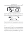
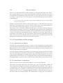
7.A design example - - - - - - - - - - - - - - - - - 7.1Introduction - - - - - - - - - - - - - - - - - - 7.2General structure of the Electronic Mailing System
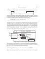
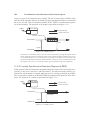
7.3Structure of the GUI - - - - - - - - - - - - - - 7.4Distribution - - - - - - - - - - - - - - - - - - 7.5Comments on the design - - - - - - - - - - - - -
-
-
-
-
-
- 64
- 64
- 64
- 66
- 68
- 68
Part 2 :
Formalization ......................................................................................71
8.Formalization and refinement of the structural decomposition
8.1"Include" relationship - - - - - - - - - - - - - - - - 8.2Provided interface - - - - - - - - - - - - - - - - - - 8.3Required interface - - - - - - - - - - - - - - - - - - 8.4"Use" relationship - - - - - - - - - - - - - - - - - - 8.5OP_Controls - - - - - - - - - - - - - - - - - - - - 8.6Generics - - - - - - - - - - - - - - - - - - - - - - -
-
-
- 72
- 72
- 73
- 74
- 75
- 76
- 76
8.6.1Generic module - - - - - - - - - - - - - - - - - - - - - - - 76
8.6.2Generic instance - - - - - - - - - - - - - - - - - - - - - - - 78
8.7Practical tips - - - - - - - - - - - - - - - - - - - - - - - - 79
8.7.1Provided interface - - - - 8.7.2"Use" relationship - - - - 8.7.3Environment or child object?
8.7.4Starting active objects - - 8.7.5Redundant systems - - - - -
-
-
-
-
-
-
-
-
-
-
-
-
-
-
-
-
-
79
79
81
81
82
8.8Summary - - - - - - - - - - - - - - - - - - - - - - - - - - 82
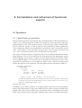
9.Formalization and refinement of functional aspects - - - - - - - - 83
9.1Operations - - - - - - - - - - - - - - - - - - - - - - - - - 83
9.1.1Specification of operations - - - - - - - - - - - - - - - - - - 83
9.1.2Implementation of operations - - - - - - - - - - - - - - - - - 84
9.2Operation sets - - - - - - - - - - - - - - - - - - - - - - - - 85
9.3Exceptions - - - - - - - - - - - - - - - - - - - - - - - - - 86
9.3.1Server side - - - - - - - - - - - - - - - - - - - - - - - - - - 86
9.3.2Client side - - - - - - - - - - - - - - - - - - - - - - - - - - 87
9.3.3Internal exceptions - - - - - - - - - - - - - - - - - - - - - - 88
9.4Practical tips - - - - - - - - - - - - - - - - - - - - - - - - 88
8
9.4.1Naming conventions - - - - - - - - - - - - - - - - - - - - - 88
9.4.2Error managers - - - - - - - - - - - - - - - - - - - - - - - 89
9.5Summary - - - - - - - - - - - - - - - - - - - - - - - - - - 89
10.Formalization and refinement of data structures - - - - - - - - - 90
10.1Description of types - - - - - - - - - - - - - - - - - - - - 90
10.2HADT and classes - - - - - - - - - - - - - - - - - - - - - 91
10.2.1Global and instance attributes and operations - - - - - - - - 91
10.2.2Aggregation and inheritance formalization - - - - - - - - - - 92
10.2.3Abstract classes - - - - - - - - - - - - - - - - - - - - - - - 92
10.3Constants, variables and parameters - - - - - - - - - - - - - 93
10.3.1Constants - - - - - - - - - - - - - - - - - - - - - - - - - - 93
10.3.2Data - - - - - - - - - - - - - - - - - - - - - - - - - - - - 93
10.3.3Data flows - - - - - - - - - - - - - - - - - - - - - - - - - 93
10.4Practical tips - - - - - - - - - - - - - - - - - - - - - - - - 94
10.4.1Naming conventions - - - - - - - - - - - - 10.4.2The "good" data - - - - - - - - - - - - - - 10.4.3HADT or class? - - - - - - - - - - - - - - 10.4.4Avoiding too many root classes: class libraries
10.4.5Controlling instances: object factories - - - -
-
-
-
-
-
-
-
-
94
94
95
95
96
10.5Summary - - - - - - - - - - - - - - - - - - - - - - - - - 98
11.Formalization and refinement of behavioural aspects- - 11.1Defining execution conditions: operation constraints 11.2HOOD execution model - - - - - - - - - - - - - 11.3State constraints - - - - - - - - - - - - - - - - - 11.4Concurrency constraints - - - - - - - - - - - - - -
-
-
-
- 99
- 99
100
101
103
11.4.1Mutual EXclusion Execution Request (MTEX) - - - - - - - 104
11.4.2Read Write Execution Request (RWER) - - - - - - - - - - - 104
11.4.3Read Only Execution Request (ROER) - - - - - - - - - - - 104
11.5Protocol constraints - - - - - - - - - - - - - - - - - - - 104
11.5.1Highly Synchronous Execution Request (HSER)- - - - - - 11.5.2Loosely Synchronous Execution Request (LSER) - - - - - 11.5.3Asynchronous Execution Request (ASER) - - - - - - - - - 11.5.4Reporting Loosely Synchronous Execution Request (RLSER)
11.5.5Reporting Asynchronous Execution Request (RASER) - - - -
105
106
107
107
107
11.6Time-out constraint- - - - - - - - - - - - - - - - - - - - 108
11.7Practical tips - - - - - - - - - - - - - - - - - - - - - - - 109
11.7.1State constraints- - - - - - - - - - - - - - - - - - - - - - 109
11.7.2Consistency of protocol constraints- - - - - - - - - - - - - 110
11.8Summary - - - - - - - - - - - - - - - - - - - - - - - - 110
9
12.A model of the global project organization - - - - - - - - - - 111
12.1The HOOD design tree - - - - - - - - - - - - - - - - - - 111
12.2The global project picture- - - - - - - - - - - - - - - - - 111
12.2.1Object space - - - 12.2.2Generic space - - - 12.2.3Virtual node space- 12.2.4Physical node space 12.2.5The global picture - -
-
-
-
-
-
-
-
-
-
-
-
-
-
-
-
-
-
-
-
112
112
112
112
113
12.3System Configuration - - - - - - - - - - - - - - - - - - 113
12.4Summary - - - - - - - - - - - - - - - - - - - - - - - - 114
Part 3 :
The design process ............................................................................115
13.The basic decomposition process
13.1The iterative process - - - 13.2The refinement process - - 13.3The basic design step - - - -
-
13.3.1Understand the problem - 13.3.2Refinement lines- - - - - 13.3.3Design activities- - - - - 13.3.4Justification of the solution
13.3.5Ordering of activities - - -
-
-
-
-
-
-
-
-
-
-
-
-
-
-
-
-
-
-
-
-
-
-
-
-
-
-
116
116
117
118
-
118
119
120
121
121
13.4A typical workout of the basic design step - - - - - - - - - 122
13.4.1Activity 1: problem definition - - - - - - - - - - - 13.4.2Activity 2: elaboration of an informal solution strategy
13.4.3Activity 3: formalization of the strategy - - - - - - - 13.4.4Activity 4: formalization of the solution - - - - - - - 13.4.5Activity 5: analysis of the solution - - - - - - - - - -
-
-
-
122
124
125
127
128
13.5Terminal implementation - - - - - - - - - - - - - - - - - 129
13.6Summary - - - - - - - - - - - - - - - - - - - - - - - - 129
14.Designing in the large - - - - - - - - - - - - - - - - - - - - 130
14.1Prime contractor's activities - - - - - - - - - - - - - - - - 130
14.1.1Activity 1: Define the logical architecture14.1.2Activity 2: Select reusable components - 14.1.3Activity 3: Decide the distribution strategy
14.1.4Activity 4: Physical architecture - - - - -
-
-
-
-
-
-
-
-
-
130
130
130
131
14.2Initiating the design - - - - - - - - - - - - - - - - - - - 131
14.3Subcontracting - - - - - - - - - - - - - - - - - - - - - - 132
10
14.4HOOD and development standards - - 14.5Configuration management - - - - - - 14.6Human factors and HOOD management 14.7Summary - - - - - - - - - - - - - - -
-
-
-
-
-
-
-
-
-
134
134
136
137
15.Design documentation - - - - - - - - - - - - - - - - - 15.1Why is documentation important? - - - - - - - - - - 15.2Relations between documentation and design fragments
15.3Generating standard documents - - - - - - - - - - - 15.4Trends in documentation - - - - - - - - - - - - - - -
-
-
138
138
139
139
140
16.Design reviews - - - - - - - - - - - - - - - - - - - - - - - 141
16.1Authoring reviews and quality assurance - - - - - - - - - 141
16.1.1Author-readers cycles - - - - - - - - - - - - - - - - - - - 141
16.1.2Quality assurance - - - - - - - - - - - - - - - - - - - - - 142
16.2Preparing reviews - - - - - - - - - - - - - - - - - - - - 142
16.3What to check in a HOOD design - - - - - - - - - - - - - 143
16.3.1Looking for the "good" design
16.3.2Design evaluation process - 16.3.3Reviewing the tree structure 16.3.4Reviewing ODSs - - - - - -
-
-
-
-
-
-
-
-
-
-
-
-
-
-
-
143
144
145
145
Part 4 :
From design to code ..........................................................................147
17.Mapping HOOD to programming languages17.1Tool support issues - - - - - - - - - - 17.2Principles of target language mapping - 17.3Ada mapping- - - - - - - - - - - - - 17.3.1Objects - - - - - - - - - - - 17.3.2"Implemented-by" relationship 17.3.3HADT and Classes - - - - - 17.3.4Exceptions - - - - - - - - - 17.3.5Generics - - - - - - - - - - 17.3.6Concurrency - - - - - - - - 17.3.7Distribution - - - - - - - - - -
-
-
-
-
-
-
-
-
-
-
-
-
-
-
-
-
-
-
-
148
148
149
152
-
152
152
153
153
153
153
153
17.4C and C++ mapping - - - - - - - - - - - - - - - - - - - 154
17.4.1Objects - - - - - - - - - - - 17.4.2"Implemented-by" relationship 17.4.3HADT and Classes - - - - - 17.4.4Exceptions - - - - - - - - - -
-
-
-
-
-
-
-
-
-
-
-
-
-
-
154
154
154
154
11
17.4.5Generics - - - - - - - - - - - - - - - - - - - - - - - - - 154
17.4.6Concurrency - - - - - - - - - - - - - - - - - - - - - - - 155
17.4.7Distribution - - - - - - - - - - - - - - - - - - - - - - - - 155
17.5Other languages - - - - - - - - - - - - - - - - - - - - - 155
17.6Adjusting mapping rules: HOOD Pragmas - - - - - - - - - 155
17.6.1Target language- - - - - - - - - - - - - - - - - - - - - - 155
17.6.2Mutex code generation control - - - - - - - - - - - - - - - 156
17.6.3Testing support - - - - - - - - - - - - - - - - - - - - - - 156
17.7Summary - - - - - - - - - - - - - - - - - - - - - - - - 156
18.Hard real-time systems - - - - - - - - - - - - - - - - - - - - 157
18.1Hard real-time specific issues - - - - - - - - - - - - - - - 157
18.2Additional features of HRT-HOOD - - - - - - - - - - - - 158
18.2.1Sporadic, cyclic and protected objects
18.2.2HRT rules - - - - - - - - - - - - - 18.2.3HRT execution model - - - - - - - 18.2.4Real-time attributes - - - - - - - - -
-
-
-
-
-
-
-
-
-
-
-
158
158
159
160
18.3HRT execution model theory - - - - - - - - - - - - - - - 160
18.4Tool support of HRT-HOOD - - - - - - - - - - - - - - - 160
19.Preserving design investment: the HOOD "standard" - - - - - 161
19.1The HOOD Reference Manual - - - - - - - - - - - - - - 161
19.2Formal definition of the ODS - - - - - - - - - - - - - - - 161
19.3Exchanging designs between tools: the Standard Interchange Format - - - - - - - - - - - - - - - - - - - - - - - - - - - - - 162
Part 5 :
A full design example ........................................................................163
20.Starting the project - - - - - 20.1Requirements - - - - - 20.2Initiating the design - - 20.3The first basic design step-
-
-
-
-
-
-
-
-
20.3.1Problem definition- - - - - - - - 20.3.2Elaboration of an informal strategy
20.3.3Formalization of the strategy- - - 20.3.4Formalization of the solution- - - 20.3.5Analysis of the solution - - - - - -
-
-
-
-
-
-
-
-
-
-
-
-
-
-
-
-
-
164
164
164
165
-
165
166
166
168
169
21.First level objects - - - - - - - - - - - - - - - - - - - - - - 170
21.1The Mission_Manager - - - - - - - - - - - - - - - - - - 170
12
21.1.1Problem definition- - - - - - - - 21.1.2Elaboration of an informal strategy
21.1.3Formalization of the strategy- - - 21.1.4Formalization of the solution- - - 21.1.5Analysis of the solution - - - - - -
-
-
-
-
-
-
-
-
-
-
-
-
170
170
171
173
173
21.2The secured driver - - - - - - - - - - - - - - - - - - - - 173
21.3Request controller - - - - - - - - - - - - - - - - - - - - 174
21.3.1Problem definition- - - - - - - - 21.3.2Elaboration of an informal strategy
21.3.3Formalization of the strategy- - - 21.3.4Formalization of the solution- - - 21.3.5Analysis of the solution - - - - - -
-
-
-
-
-
-
-
-
-
-
-
-
174
174
174
175
175
21.4Generic_Gate - - - - - - - - - - - - - - - - - - - - - - 175
21.4.1Problem definition- - - - - - - - 21.4.2Elaboration of an informal strategy
21.4.3Formalization of the strategy- - - 21.4.4Formalization of the solution- - - 21.4.5Analysis of the solution - - - - - -
-
-
22.Other objects - - - - - - - - - - - - - 22.1Motors library - - - - - - - - - - - 22.2Lights_Controller and Pressure_Sensor
22.3Protected counter and Flip_Flop- - - 22.4Gates instantiations- - - - - - - - - 22.5Hard_Configuration - - - - - - - - 22.6System configuration - - - - - - - - -
-
-
-
-
-
-
-
-
-
-
-
-
-
-
-
-
-
-
-
175
175
176
177
177
-
178
178
178
179
179
179
179
Annexes ...............................................................................................181
A.Abbreviations - - - - - - - - - - - - - - - - - - - - - - - - 182
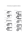
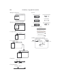
B.Summary of graphical notation - - - - - - - - - - - - - - - - 183
C.Glossary - - - - - - - - - - - - - - - - - - - - - - - - - - - 185
D.References - - - - - - - - - - - - - - - - - - - - - - - - - - 188
E.ODS of the water-lock system - - - - - - - - - - - - - - - - - 190
F.Index - - - - - - - - - - - - - - - - - - - - - - - - - - - - - 217
13
Table of figures
3-1 A HOOD checking tool (Concerto, SEMA-Group)
3-2 HOOD in the development activities
4-1 Basic representation of a HOOD object
4-2 Required objects
4-3 An active object
4-4 An ODS editor (Stood, from TNI)
4-5 Structure of the ODS
4-6 Operations of a television set
4-7 HOOD representation of a television set
4-8 Transmitting a connection to inner children
4-9 The television set with "use" relationships
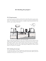
4-10 A painting robot.
4-11 The driving device.
4-12 Uncles and operations implemented by a child
4-13 Using an environment object
4-14 Representation of an OP_Control
4-15 Using an OP_Control
4-16 An object with an operation set
4-17 An object with an open operation set
5-1 Data flows
5-2 Graphical representation of a HOOD abstract data type.
5-3 A fruit basket HADT
5-4 Aggregation arrow
5-5 Representation of a class.
5-6 Inheritance arrow
5-7 Client-server view of the company
5-8 Structure view of the company.
6-1 Exception flows
6-2 A generic list
6-3 Instance of a generic
6-4 Similar instantiations for the engines of an airplane
6-5 representation of a virtual node
6-6 VN description of an airplane
6-7 A hierarchy of networks
7-1 Client-Server view of the EMS
31
32
35
35
36
36
37
39
40
41
42
43
44
44
45
46
47
47
48
49
52
53
54
54
55
56
56
58
59
60
61
62
62
63
65
14
7-2 Structure view of the EMS
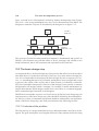
7-3 Client-Server view of the GUI
7-4 Structure view of the GUI
7-5 Allocation of objects to VN.
7-6 An alternative design of the EMS.
8-1 Client-server view of a generic
8-2 Structure view of a generic
8-3 Dependencies of an instance
8-4 Circular "use" between objects.
8-5 A complex "use" structure
8-6 Reducing "use" complexity
8-7 Implementing some parent operation
8-8 Using another child
8-9 Model of a redundant system.
9-1 Operation sets implemented by children
10-1 A class and HADT library
10-2 A client of the library, structure view
10-3 An object factory
11-1 A stack with constrained operations
11-2 Object execution model
11-3 Representation of an OSTD
11-4 A microwave oven
11-5 Decomposition of the microwave oven
11-6 OSTD of the control system of the microwave oven
11-7 A network interface
11-8 HSER protocol
11-9 LSER protocol
11-10 ASER protocol
11-11 RLSER protocol
11-12 RASER protocol
11-13 HSER_TOER protocol
12-1 the HOOD design tree
12-2 The HOOD Design Model as a set of spaces and hierarchies
13-1 A HOOD initial model
13-2 A refinement of the initial model
13-3 Graphical description of the airline reservation system.
16-1 A star diagram
17-1 General structure of a call to a constrained operation.
17-2 A HOOD structure
20-1 The water-lock system.
20-2 Global view of the lock system.
20-3 Breakdown of the lock system
21-1 Mission manager, client-server view
65
67
67
68
69
77
77
78
79
80
80
81
81
82
86
96
96
97
100
100
102
102
103
103
105
106
106
107
108
108
109
111
113
117
118
127
142
150
152
164
165
169
172
15
21-2 Mission manager, structure view
21-3 OSTD for the secured driver
21-4 Client-server view of the Generic_Gate
21-5 Structure view of the Generic_Gate
22-1 Client-server view of the motors library
22-2 Structure view of the motors library
172
173
177
177
178
179
16
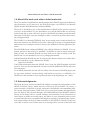
1. Preface
1.1 Introduction
HOOD (Hierarchical Object Oriented Design) is a design method, which is used after
the requirements analysis activities and covers architectural design, detailed design
and coding1. The method resulted from merging methods known as abstract machines and object oriented design and was further adapted to the needs of European
software industry as an attempt to unify and integrate object orientation and advanced
software engineering concepts and notations [Heitz92].
1.2 History of HOOD
The HOOD design method appeared in 1987, at the request of the European Space
Agency (ESA) for a design method that would fit the needs of complex, real-time
software, such as those encountered in space applications; the method had to fit the
Ada programming language as its target language. The bid was won by a consortium
consisting of CISI Ingénierie (France), Matra Marconi Space (France), and CRI (Denmark). HOOD resulted from merging Matra's experience with Abstract Machines
[Mach85] and CISI's experience with Object Oriented Design [Booch86], while CRI
provided its experience on the formal definition of the method. This resulted in the
first version of the method, HOOD 1.
HOOD 1 was never really used for actual projects, but it served as a basis for an improved and more industrial version, HOOD 2. HOOD 2 was used industrially for the
EFA (Euro Fighter Aircraft). The notion of a common representation of designs (the
SIF, explained in section 19.3) allowed to freeze the interfaces between the subcontractors.
In September 1989, HOOD 3.0 was released by the HOOD Technical Group (HTG),
a group of experts founded by ESA which is in charge of the maintenance and evolution of HOOD. In July 1992, HOOD 3.1 [HRM3.1] was adopted by the HOOD User's
Group (HUG) as the official release of the method. It was an evolution from release
3.0 that incorporated feedback from over two years of experience on various projects.
After an evaluation phase on small pilot projects, the method was chosen for the COLUMBUS Manned Space and ARIANE-5 programs. Since, it has been adopted by
1. Chapter 2 will detail the precise definition of these terms.
16
Preface
EUROCOPTER, the French Navy and by several other large projects in aerospace,
defence, transport, energy and nuclear applications.
However, the context of software development is a moving target. Object oriented
method have gained wide acceptance in the meantime, extensive use of HOOD
showed some difficulties, and there was a desire to support other programming languages. At the same time, C had moved to C++ [Stroustrup91] and Ada 83 [Ada83]
had been replaced by Ada 95 [Ada]. For these reasons, an update of the method became necessary. This was achieved in 1995 as HOOD 4 [HRM4]. This is the current
state of the method, and the one which is described in this book.
With thousands of engineers trained in Europe and the availability of several tool sets
and companies providing support for using the method, HOOD is spreading continuously within the industry. The Hood User’s Group has been set-up as an international
non profit organization and is in charge of controlling the evolution of the method.
1.3 Structure of the book
This book is organized in four parts that provide a gradual approach to the HOOD
method.
Part 1 introduces the basic notions of HOOD; starting from general software engineering notions, it provides enough information to allow the reader to understand an
existing HOOD design, at least at the level of the general structure. The part concludes with the presentation of a full HOOD design.
Part 2 then goes into deeper details, and a more formal presentation of the method;
this corresponds to what the reader needs to know about the formalism to write a new
HOOD design.
Part 3 discusses the methodological aspects, i.e. the process that brings from a white
page to a full design.
Part 4 is a full scale example, that shows a full design from the early phases on down
to actual code.
Annexes are included to provide the reader with supplemental information, such as
bibliography, summary of acronyms and notations, and a full index.
As is common nowadays, we have used a Courier font to represent programs and
names that appear in the textual formalism of HOOD.
Paragraphs of this style provide additional information of less importance, or extra details
on a particular point. They can be skipped at first reading.
About this book and other related materials
17
1.4 About this book and other related materials
There is a number of publications and documents about HOOD. Apart from this book,
two documents are of interest to the HOOD designer: the HOOD User Manual
(HUM) and the HOOD Reference Manual (HRM).
This book is intended to give a first introduction to HOOD and to present a general
overview of the method; it is not intended to cover all the details that are necessary
before being able to start a full-scale project with HOOD, but rather present the main
ideas that would allow a project manager to make a conscious decision when choosing a design method.
The HOOD User Manual [HUM96] aims at presenting more technical details for
those who intend to use HOOD. It provides a thorough coverage of implementation
details and covers examples on how to best use the method for various application domains.
The HOOD Reference Manual [HRM4] is the official definition of HOOD. It is very
formal, and serves the need for a "standard" of HOOD, in order to insure interoperability of tools. An educated HOOD user may look at it in order to clarify some fine
details, but it is not intended to serve as a pedagogical manual.
Information about HOOD can also be found on the Internet. Most tool vendors have
their site, and there is a site dedicated to HOOD:
http://www.hood.be.
You'll find information about the HOOD User Group, the HOOD method itself and
its tools. You can also download the reference manuals (HRM and HUM) and some
relevant papers.
Let us finally stress that no book will ever allow one to become a HOOD designer (nor
for any other method): actual training with hands-on exercises, availability of a
HOOD tool, and assistance of an experienced tutor in the beginnings, are a must.
1.5 Acknowledgments
This book has been written on behalf and with the constant help and guidance of the
HOOD Technical Group, which deserves collectively all my thanks. Of course, a
group is mainly a collection of people, and some of them had a real outstanding influence on the form and content of this book. First, my deepest thanks and appreciation
go to M. Heitz (CISI), the main designer of HOOD and head of the HOOD Technical
Group, for his many advices, careful readings, and sometimes lively discussions on
issues where we didn't necessarily agree, but where we were fortunately able to come
to conclusions that were acceptable (and happily accepted) by all participants. I gratefully acknowledge the help of other members of the HOOD Technical Group who
were able to devote some of their time to reviewing earlier versions of the book and
18
Preface
participating in the various coordination meetings: E. André (SEMA Group), P. Dissaux (TNI), C. Pinaud (Matra Marconi Space), and J-M Wallut (CNES). I would also
like to thank people who provided me with some valuable inputs in the form of comments, reports, papers, and other documents. I was not always able to include directly
their information, but their participation helped to shape the form of the book. This
includes A. Burns (University of York), A. Canals (CISI), D. Minguillon (CNES), P.
Panaroni (INTECS), and A. Wellings (University of York).
The help of companies that provided access to their tools for my experiments is gratefully acknowledged: TNI (Stood tool) and SEMA-Group (Concerto tool).
Finally, I'd like to thank my "naive" reviewer Jérémy Rosen. He was instrumental by
knowing nothing about HOOD beforehand, and contributed a lot to making this book
more understandable.
Part 1 :
Industrial software design issues
Software design is an integral part of the development of many industrial products;
too often however does it rely more on wizardry than on industrial, fully mastered
process.
What makes the approach we describe here unique, as supported by the HOOD method, is that it takes into consideration many industrial constraints within the design
framework itself. Such constraints include working with subcontractors, hardware
constraints, reuse, and long-term life cycle.
2. Hierarchical and object oriented design
issues
In this chapter, we will recall the most basic notions of object oriented design and other software engineering principles, which form the basis of HOOD as well as many
of other design methods. The goal is simply to explain how some basic terms are used
in this book, since there are many diverging definitions of them.
2.1 Design: breaking software into modules
Before discussing about object oriented design, it is important to understand what
design is about. A software product is generally too big to be dealt with as a single
big chunk; it is therefore decomposed into modules. Design is the activity that starts
after requirements analysis and whose goal is to identify and define software modules.
Actual production of the modules is the task of the coding and testing phases.
The goal of analysis is to provide a high level description of the requirements, while
design is oriented towards identifying and describing software solutions. Although
traceability from analysis to design is of utmost importance, it does not mean that the
design should be a mere rewriting of the analysis. On the contrary, design is a creative
process that takes into account the constraints and paradigms of computer software.
It must find a solution which is, at the same time, a satisfactory solution to the problems described by the analysis phase, while being efficient (in the broad sense) from
a software point of view.
For example, the analysis often describes the problems by classifying the data in
terms of "is a" relationships: a client "is a" person, a vibration detector "is a" sensor,
etc. This can be sometimes translated at design level using the inheritance mechanism, but it is in no way mandatory, and alternative solutions (as always) should be
investigated, and may well be more appropriate. Sharing properties at analysis level
does not necessarily involve sharing implementation code!
Object orientation
21
2.2 Object orientation
We said that the goal of the design phase was to define modules. How to decompose
a software piece into modules is what differentiates the various methods; it is therefore a central part of every design method.
Early design methods were functionally oriented: modules were defined according to
the main functions of the program, and to the order in which they were performed.
This approach was, and still is in many cases, very effective, but over time a number
of drawbacks appeared, especially due to the strong temporal coupling between modules, difficulties in defining reusable modules, inability to deal with concurrency, etc.
A solution to a problem can normally be described using very common notions from
the real-world. For example, it is quite natural to tell people to click on a button on
the screen with the mouse. Of course, there is no real button on the screen, and even
the fact that the pointer on the screen somehow follows the movements of the mouse
is a pure artifact; however, these computer objects behave as if they were real objects,
at least as far as their computer usage is concerned. They are abstractions of real
world objects. Object oriented design consists in decomposing a program into modules that represent objects, as abstractions of real world objects. Since objects normally have both properties (colour, shape, etc.) and operations (being pressed for a
button, etc.), computer objects embed both data structures and program structures
that belong to a common entity of the problem domain. This is known as encapsulation, and is often used as a definition of a computer object.
2.3 Abstract state machines
An abstract state machine is the most elementary way of representing an object. It is
a module that encapsulates the states of the object and provides operations to act on
this state, or to direct the object to perform some actions. Since the object has states
that can influence its behaviour, it is called a state machine, or automaton. Moreover,
these states are normally hidden. In Ada, the machine would be implemented by a
package, and the states would be encapsulated as variables of the package body. In
C++, the variables would not appear in the ".h" file that defines the interface. Since
the actual state variables are hidden to the external world, their internal structure can
be quite different from what appears to be to the users of the object: the real state is
abstract.
For example, a rail needle appears to have only two states: Left and Right. Actually,
the object that deals with the needle has a much more complicated view: while it is
moving, the needle is neither Left nor Right; moreover, the object must be able to deal
with complicated cases, like when the needle is frozen, and several attempts must be
made to move it from one position to the other one. But thanks to the encapsulation
mechanism, such a complexity is hidden to the user.
22
Hierarchical and object oriented design issues
2.4 Abstract data types
When an object is represented in a computer as an abstract state machine, there is only
one occurrence, or to use the official term, only one instance of the object. One module equals one object. It is however often the case that data need to be exchanged between objects, or that similar objects must be created. There is a need to describe a
common model for those data, from which many instances can be made.
Such a model that allows to declare several instances with the same properties is, in
computer language terms, a data type. A data type is used to represent entities of the
real world: a length, an employee's salary, a telemetry record, etc. The view of the
data that makes sense for the user of the type is called the abstract view; but this abstract view has to be translated into the much simpler types that can be handled by the
computer. This simpler view is called the implementation of the data type. For example, a printable character represents an element that can be read, but it is generally implemented as a byte in the machine.
Normally, the user should not depend on the representation of the abstraction. If the
language (or the method) allows to define the data type in such a way that the actual
representation is hidden and that the data type can be operated upon only through a
well defined interface corresponding to the abstract view, then only this abstract view
is accessible, and the data type is called an abstract data type.
2.5 Aggregation
Real world objects are generally made of parts, that are themselves objects that are
assembled to build a higher level, composite, object. This is also true of software objects: a button is made of a frame and a label, a pixel includes X and Y coordinates as
well as a colour, etc. The process and relationships by which an object is made of several sub-objects is called aggregation.
Note that the properties of an aggregating object are generally different from the properties of the aggregated parts. An aggregating object has its own properties, and the
aggregated parts only serve to implement the global object.
Aggregation is a powerful mechanism for constructing objects, and some design
methods do not require any other form of relationships between objects. To differentiate these methods from others that rely on the mechanism of inheritance (presented
next), they are sometimes called object based methods.
2.6 Classes and inheritance
It is sometimes necessary to build a new type of object by extending the properties of
an existing type. For example, a monitoring system to detect a current overload can
Exceptions
23
be thought of as a normal amperemeter (which may already exist) with an extra feature that allows it to trigger an alarm when some predefined level is exceeded. In this
case, it makes sense to define the monitoring system from the existing amperemeter,
adding the new functionalities. Since the monitoring system will still have all the
properties of the amperemeter, it is, from an abstraction point of view, an amperemeter. It is said to inherit from the amperemeter, and is considered to belong to the class
of all amperemeters. A class is a kind of abstract data type which belongs to a set
whose members are interconnected by inheritance relationships, allowing sharing of
common properties.
Many people claim that inheritance is the most important feature of object orientation.
It must be reminded here that often, the same effect can be obtained both by inheritance and aggregation. For example, an alternative solution to the previous example
could have been to define the monitoring system as a stand-alone entity, that would
include (aggregation) an amperemeter and an alarm system, but that would not have
been considered as being an (belonging to the class of) amperemeter.
This is really a matter of different ways of modelling real world objects, and there is
no absolute best way of doing it. In general, aggregation provides better encapsulation
and information hiding, while inheritance allows for quicker development and code
reuse. Which one to chose depends on the project's constraints.
2.7 Exceptions
Normally, an operation provides some kind of service. Sometimes, the required service can simply not be provided: either the parameters provided by the caller are inconsistent, or some external event prevents the operation from being able to do its
business... Defining the semantics of an operation when problems are encountered is
as important as defining the behaviour when all is well. Too often, this part of the semantic is undefined, and can lead to unexpected behaviour when such a condition is
encountered: when what would happen is not specified, the caller presumes that it
cannot happen.
Therefore, a complete description of the behaviour of an operation must include the
conditions imposed on the caller for the operation to be able to perform its task (preconditions) and the definition of error conditions that can prevent the operation from
succeeding. If such a condition is encountered, the operation must signal to the caller,
in a non-ambiguous way, that the required service was not performed as specified (i.e.
not fully completed or not performed at all). This kind of signal is called an exception.
Some programming languages (including Ada and C++) provide a built-in mechanism for signalling exceptions. Other languages (including C and FORTRAN) have
no such device, and exceptions must be signalled using a return code, for example.
However this does not change the principle: the caller has to know whether the re-
24
Hierarchical and object oriented design issues
quested service was performed according to its expectations/specifications or not, i.e.
whether an exception has occurred or not.
2.8 Generics
Sometimes, it is discovered that a number of objects are made according to a given
pattern, and differ only by some types or secondary operations. For example, the notion of a bounded list does not depend on the kind of data that is held into the list. It
would not be cost-efficient to redesign as many lists as types being manipulated; it is
better to gather this commonality in an object template. This corresponds to the notion
of templates in C++ or generics in Ada.
A bounded list can therefore be seen as a parameterized object, whose parameters are
the type of the data being manipulated and the maximum size of the list. Such a generic object cannot be used in itself: it can only be used to create instances, which are
regular objects obtained from the generic by providing values to the parameters. For
example, an instance of the bounded list could be a list of Measure_Points of
maximum size 100.
Since instances are all derived from a common model, a change in the model will automatically update all instances, making maintenance much easier than by manual duplication of a "reference" object.
2.9 Concurrency
Most programs are defined as a list of sequential actions, i.e. a program is viewed as
various statements that are performed by a computer one after the other. However, in
real life, it is often necessary to deal with several things at the same time: in a tennis
video game for example, it is necessary to control the movements of both paddles and
of the ball simultaneously. When one (or several) computers have to handle different
activities concurrently, it is called concurrent programming.
There are several ways to deal with concurrency; the most common one consists in
separating the problem as several activities, called threads or tasks1, each of them being purely sequential, but being executed in parallel with other threads. Note that
many real-world objects do have a concurrent behaviour of their own; a microwave
oven stops after the required time, without the cook having to stay in front of it with
a watch! The same effect can be obtained for computer objects, if they include one or
several threads. Such objects are called active objects.
1. In this book, we’ll use the more general term "thread" to refer to the concept of "light weight process". We’ll keep the term "task" for Ada tasks.
The client-server model
25
Concurrent programming induces a number of difficulties that have to be dealt with,
that are not found in sequential programming. The most important of the issues are:
• Implementability. Although a convenient tool, concurrency may require support
from the operating system or the underlying executive, which is sometimes not
available.
• Communication. Sometimes, different threads need to exchange or share data. A
special mechanism must be provided to that effect; examples of such mechanisms
are mailboxes and rendezvous.
• Synchronization. Sometimes, a thread needs to know whether another thread has
reached some point in its execution, or a thread must wait until it receives an indication from another thread that it can proceed. A special (and important) case of
synchronization is needed when two threads can access some variable, or other
shared element, at the same time. Special care must be taken to ensure that no chaos results.
Note that communication and synchronization are not orthogonal issues. For example, the
rendezvous is a synchronous communication, since both threads that communicate are in a
well defined point in their execution. Threads can be desynchronized by introducing an intermediate agent thread. On the other hand, mailboxes provide asynchronous communication, since the sending thread knows nothing about the state of the receiving thread.
Synchronization can be achieved by adding an extra message exchange.
• Race conditions. Sometimes, the correct behaviour of a program depends on the
precise order in which threads perform a certain action, but it may be difficult to
guarantee that the right order happens in every case, since threads may execute
concurrently. When incorrect behaviour results from threads executing certain actions at inappropriate times, it is called a race condition. Race conditions are the
cause of very hard-to-find bugs, since they may never happen under debugging
conditions, but only on the real working system. Some common synchronization
primitives used to avoid race conditions include semaphores, monitors, and protected objects.
2.10 The client-server model
A useful paradigm when dealing with complex systems is to use a client-server model. It consists in breaking the system into modules that act either as servers, defined
by a number of services that can be requested from them, and clients that use these
services. The principle is that a server provides the services to a number of clients,
without having to know anything about the client; on the other hand, the client uses
the services, as defined by the specifications of an interface, without having to know
how the service is implemented. A real-life example of a client-server model is a postoffice, where clerks provide services (sell stamps, accept parcels) to anyone who is in
line, while the clients queue up at the booths without having to know about the mechanisms involved for sending a letter across the country.
26
Hierarchical and object oriented design issues
2.11 Issues with distributed systems
A complex system rarely involves only one program running on one machine, but
rather needs the cooperation of several programs, often distributed on a network of
computers, or several computers connected by an industrial bus. This presents new
challenges to design, since it is far from obvious to determine how to best split the
parts of the system over the hardware configuration.
It is often tempting to account for distribution right from the start of the design. With
this technique, a physical architecture is first defined, then it is decided which functions are to be implemented on which computers. Then, when a part of the system
needs services from another part on another machine, it calls it through network services. The network is thus visible as a top element of the project. Many projects have
used this approach, but experience has shown that it had severe drawbacks. The most
important one is that the architecture of the software is driven by the hardware. If the
hardware design evolves, or if it appears that the initial distribution of software modules over the hardware is unbalanced, it is often necessary to move some parts from
a machine to another one. If the software is driven by the hardware, this implies a major redesign of the software architecture, sometimes very late in the project's life cycle.
Moreover, the precise hardware configuration may not even be fixed at the beginning
of a project. Now that portable, standardized, middleware solutions (such as CORBA
[OMG91]) are available, and that rapid evolution and changing prices of hardware
makes economics forecasts difficult, it is increasingly the case that the supporting
hardware is chosen late in the development process.
For these reasons, it is generally regarded as a better strategy to design the software
independently from the distribution issues, and then deal with distribution as an independent step. On the other hand, a hardware architecture has to be designed, often
quite early in the project. This means that both aspects must evolve concurrently, and
that there must be a simple, versatile, and powerful way of mapping the software design over the hardware structure.
3. Overview of HOOD
HOOD is an architectural design method, helping a designer to partition the software
into modules with well defined interfaces that can either be directly implemented or
further partitioned into modules of lower complexity. It supports functional approaches as well as object based and object oriented design. It integrates both modular programming, centered on client-server and composition relationships, and inheritance
programming.
HOOD was developed as a design method, with special consideration for other development activities that occur at the same time: smooth integration with requirements
analysis, concurrent development of independent parts, automated code generation
and testing, client-server and post-partitioning support. The integration of these aspects results from the return of experience gained from using previous issues of the
method on industrial projects, thus making HOOD the architectural design method of
choice.
3.1 Objectives of industrial software design
Complexity
There are several issues that make software development such a challenging endeavour. But encompassing all the others is the issue of complexity. It has long been observed that the human mind is limited in its ability to handle complexity [Miller56];
at the same time, software becomes increasingly complex. Therefore, as Booch points
out [Booch91], "the fundamental task of the development team is to engineer the illusion of simplicity". But this does not happen through wishful thinking: design methods are intended to guide the developer into achieving this goal.
One of the issues that makes software complex is that there are several aspects to it:
what to do, when to do it, and how to do it. A design method can help if it separates
concerns, allowing the various aspects to be dealt with without introducing any
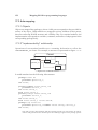
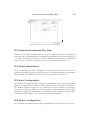
coupling between them.
Reuse
Software is rarely entirely new; reuse of existing modules in new projects is often a
concern. It is not something that happens by chance, and a structure is necessary in
order to identify the pieces that can be reused, at design level as well as at code level.
28
Overview of HOOD
Hardware vs. software
Most modern systems involve a network of computers, or at least several collaborating processes. The hardware architecture is often driven by external considerations,
such as cost, power consumption, network bandwidth, etc., that do not necessarily
map the software constraints; on the other hand, software is developed concurrently
with hardware, and cannot rely on a definitive hardware architecture. Moreover, software changes and evolution should not have an adverse effect on the effectiveness of
hardware usage. For these reasons, a design method should allow concurrent development of hardware and software, and provide for a late mapping of software upon
hardware as well as for an easy remapping if necessary.
Traceability
It is a fact of life that requirements keep changing, long after design has started. Evaluating the impact of a change is difficult, but it can be eased if there are good traceability documents, that tell precisely which parts of the design are impacted.
Partitioning
Finally, large projects are seldom built as one piece. There is often a prime contractor
who delegates part of the development to several subcontractors; the global design
process is split into several concurrent activities. Even if the project is completed
within a single company, it often requires several development teams. This implies
that software must be partitioned between the various proponents, and that synchronization and consistency checks have to be done between loosely related participants.
This aspect has a real impact on software design: what good is a software architecture
if it is not feasible in time by the people in charge? It also implies that a design method
must provide a common language for expressing strictly defined interfaces, allowing
subcontractors to understand what they have to do, and allowing the prime contractor
to check the resulting design against the specifications.
3.2 The HOOD approach to design
HOOD is a design approach, that uses standardized (textual and graphical) formalisms to express the results of the design. A number of rules, elaborated from industrial
experience, apply to the design, and these rules can be checked by automated tools.
The final goal is to achieve the best possible quality design.
3.2.1 The hierarchical approach
Since HOOD is a design approach, it provides a framework to guide the developer in
the design activity, by describing and refining a software model from abstract structures and concepts towards machine code. Each step produces pieces of text reflecting
the associated design activity, that can be reviewed and checked against quality crite-
The HOOD approach to design
29
ria. Moreover, HOOD is a hierarchical approach: it defines high level structures that
are refined into more detailed ones; the designer never has to cope with all the
project’s details at the same time. This dramatically reduces the complexity the designer has to deal with at any moment. The hierarchy can be organized according to
management constraints, such as subcontracting or other organizational aspects.
An original aspect of the approach is the separation of concerns: each module includes separate descriptions for interfaces, functional aspects, data modeling, and behavioural aspects. The descriptions are kept independent, making it easy to apply
dedicated development skills, and rigorous methods. For example, Rate Monotonic
Analysis [Klein93], State-Transition or Petri nets [Reisig85] analysis, automated test
scenario generation, can be applied to the behavioural part without relying on an implementation of the functions, while functional parts use abstract state machines, preconditions and post-assertions for functional proofs.
Separate hierarchies are defined for reusable software components. This allows for
introducing a reuse policy as a natural step in design. Moreover, the notion of system
configuration (see section 12.3) allows precise tracking of which components (design
pieces as well as software components) are being used in each project.
Traceability with requirements as they are refined, followed by refined solutions, is
still a problem in managing large projects. HOOD refinement properties support a development approach that encompasses the different design phases and helps ensuring
consistency and traceability of a design solution, from requirements to implementation, even in the presence of unstable or evolving requirements.
Finally, the method includes an abstract model of distribution (the virtual nodes, see
section 6.3) which is orthogonal to the structural design. A separate step is used to
map the logical architecture into the physical one; this ensures independence and ease
of relocation between software and hardware.
3.2.2 Balancing graphical and textual formalisms
HOOD includes the definition of a graphical description (i.e., boxes and arrows). It
provides an abstraction of a solution with a clear, high level and easy-to-understand
formalism. It offers a reduced, but consistent view of objects, and allows hierarchical
refinement and easy understanding of the solution.
The notation is intended to support the approach, not to replace it. It is a convenient
way to reason about software and to make a mental picture of its architecture, but not
more. Therefore, the graphical description is complemented by a textual description
which includes all details. It allows formal expression and refinement of the object's
characteristics and properties by an Object Description Skeleton (ODS1). This con1. HOOD uses a number of abbreviations like this one. Annex A summarizes those that are used in
this book.
30
Overview of HOOD
cept helps structuring the descriptions into separate fields which support appropriate
control and program description notations. Finally these descriptions are translated
into a target programming language (Ada, C, C++, or FORTRAN, for example).
The textual notations leave provisions for both informal and formal texts, allowing
the definition of a documentation skeleton which can serve as a framework for a step
by step integration of advanced notations (like Petri nets for example). Tools can be
used to capture and formally verify the characteristics of objects.
The graphical notation recalls the context of the design piece, but hides most implementation details, thus decreasing the design complexity, while the textual notation
keeps all the details, including full traceability and control of dependencies between
modules, with full consistency checking. These notations allow to use powerful structuring concepts for describing and organizing a system as a set of interconnected hierarchies of objects.
3.2.3 Design quality control: HOOD rules
Proper usage of HOOD requires obeying by a number of rules. Rules may appear as
a nuisance to the stand-alone designer if they are perceived as arbitrary restrictions;
on the other hand, they can be of great help when they are perceived as providing
guidance, common guidelines, and thus forming the basis of quality assurance. The
rules are summarized in section 16 of the HOOD Reference Manual. Each rule is assigned a number for easier reference, that includes a letter that classifies the rule, and
an ordinal number. The keys for the rule letters are as follows:
C
G
I
O
Consistency & completeness
General definitions
Include relationship
Operations
P
R
U
V
Provided interface
Required interface
Use & inheritance relationships
Visibility
HOOD rules are of three kinds: definitions, methodological rules and usage rules.
Definitions are simply statements of the main method elements. Methodological rules
result from the very structure of the method’s entities . They must be enforced, or else
the design would be inconsistent. Usage rules come from industrial experience. They
are intended to help the designer and provide a basis for quality assurance, but there
may be cases where an out-of-norm situation may lead to not obeying by the rule.
Such exceptions must be documented and justified in the design documents.
In the book, we introduce rules as we encounter the corresponding situation. They are
presented in a special box, to stress that they are formal rules, as follows:
Reference number
Text of the rule.
Kind
The HOOD approach to design
31
The reference number is as given in the reference manual, the kind is one of "Definition", "Methodological", or "Usage", and the text is the text of the rule as given in the
reference manual. Note that "Usage" rules are not formal rules, and thus have no reference number.
There are also code generation rules, which define how to map HOOD concepts onto target
languages. We will not address these here, since they are mainly a concern for the tool designers.
3.2.4 Supporting the method: HOOD tools
HOOD was designed right from the start with consideration for tools support. What
this means is that tools were not added later, but that it was rather considered that tools
were in any case necessary for any serious software development. The notations, the
rules, and even the format of the design documents have been designed for being produced by tools and for being reviewable by tools.
What do the tools bring to the designer? First, they help with the design activity itself,
by providing graphical and textual editors. They can generate documents according
to various documenting standards (like DOD-2167A, DOD-198A or ESA PSS-05
[BSSC91]). They check and insure consistency between the representations. They
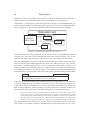
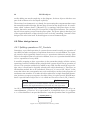
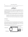
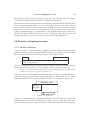
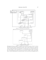
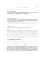
can enforce HOOD rules, and provide various analysis of the design. For example, a
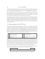
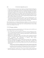
typical output of such a tool is represented on figure 3-1.
Figure 3-1 : A HOOD checking tool (Concerto,
SEMA-Group)
Moreover, it is possible to extract parts of the design for processing by other tools,
like proof making tools for example.
Several tools are currently available from various vendors, and this is a competitive
market. HOOD defines a standard representation of designs (the Standard Inter-
32
Overview of HOOD
change Format, or SIF, see section 19.3) that allows a design produced by a tool to be
read by a different tool. This way, several subcontractors on a project need not use the
same tool in order to exchange design documents.
3.3 From analysis to design: scope of HOOD
HOOD supports identification of a software architecture after requirements analysis
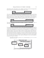
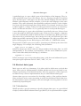
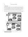
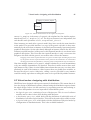
activities and leads naturally into detailed design where operations of objects are further designed and implemented. This detailed design description may be further refined into target language descriptions up to a point where the target code can be
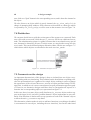
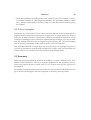
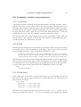
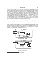
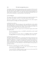
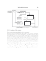
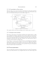
generated. Figure 3-2 indicates HOOD applicability within a simplified life cycle
model.
Requirement analysis
Architectural design
Detailed design
Coding
Testing
Figure 3-2 : HOOD in the development activities
Although HOOD is not a requirements analysis method, it handles "design requirements analysis" activities during the transition from requirements analysis to design.
From this point on, it covers all phases of architectural design and detailed design
down to coding, which can be greatly automated, and testing.
HOOD concepts are intended for easy integration of design with other development
activities. More precisely, HOOD object properties have been defined in order to ease
interface mastering, testing and integration in the context of parallel, multi-people
team developments. This implies that HOOD is rather aiming at better filling the
needs of the prime contractor and integrator than those of the low level programmer.
3.4 HOOD compared to other methods
As noted above, the challenge for a design method is to guide the developer in order
to design complex software while giving it the look of simplicity. Many design methods fell into the pitfall of trying to accurately represent all of the complexity of the
problem to be solved, while HOOD focuses on hiding the complexity by organizing
the development in such a way that the designer, at any one moment, only has to cope
with a well defined and bounded part of it that is within the reach of human understanding. This is the key concept that introduced the notion of hierarchical design.
Analysis methods, such as OMT [Rumbaugh91], are very efficient methods for representing the properties of system. As such, they are very fit as a requirements analysis method, and can actually be used as the input to a HOOD design. On the other
Summary
33
hand, there is no clear module interface definition, so using it as a design method will
badly lack context restriction, interface definition, testing and integration support.
The so-called object oriented methods (actually, inheritance based methods) provide
excellent flexibility when in the exploratory stages of a project; but it is often at the
cost of difficulties in traceability, testability and maintenance. By limiting inheritance
to data structures in a very controlled way, HOOD achieves many of the benefits of
these methods, without the drawbacks.
Finally, a special mention should be made to explain the relationships between
HOOD and UML, the Unified Modelling Language [UML]. UML is a very general
language, that can be used to describe various systems; it has been designed by merging concept and notations from OMT, Booch and OOSE methods. UML includes a
graphical representation of the formal language. UML (purposely) does not include
any design process; it is rather expected that various design processes be defined using this language. The general notation can be specialized, by identifying certain uses
of the constructs as bearing some special semantics; such specializations are called
stereotypes.
HOOD concepts can be described using UML, adorned with a number of ad-hoc stereotypes, and the HOOD method itself can be described using UML as a meta-model,
the same way as UML is itself described using its own meta-model. In a sense, HOOD
can be seen as one of the many possible design processes obtained by specializing
UML. HOOD is not UML, but HOOD is compatible with UML.
HOOD notations differ in a number of places from UML notations. On one hand,
when the same need arises in both approaches, it would make no sense to invent a different shape of arrow, and HOOD uses the same (or similar) notations as UML; on
the other hand, when a stereotype is a cornerstone of the method, it does make sense
to identify it by a special symbol to make it more easily recognizable than a simple
annotation on a standard diagram. Deciding which level of concepts is worth a special
symbol is a matter of judgement, but the apparent differences between the notations
should not be taken to be more than what they are: various ways of representing the
same underlying model, and it is absolutely possible to design a HOOD tool that
would, at a user mouse click, present the design using either notation.
3.5 Summary
HOOD is a hierarchical design approach that incorporates the notions of object oriented design into an industrial process. It includes a notation and a design process.
The formalism is supported by a set of rules which are enforced by tools.
4. HOOD objects
4.1 Objects and modules
Objects are the most basic entities manipulated by HOOD. There are various kinds of
objects, that will be detailed all along this book; some represent "objects" in the sense
of classical OO techniques, but others do not. To avoid ambiguity, we shall use the
term class instance when we want to refer to an object as an instance of a class.
A HOOD object is a basic module, a conceptual unit of design and encapsulation. It
may have an internal state, and is defined by the services it provides. These services
are used by other objects, which act as clients for this server object. A fundamental
aspect of HOOD is that interactions between objects always follow this client-server
model: a server is an object that provides services, but does not know to whom the
services are provided. On the other hand, a client is an object that uses the services,
but does not know how the services are provided.
Every HOOD server object features a provided interface that defines the services that
can be used by clients. Clients do not need to know (and, to be honest, cannot know)
how these services are implemented. This enforces the software engineering principle
of encapsulation. But of course, clients do know which services they need! Every
HOOD client object must also include a required interface, to describe which services
are being used.
A server may require other services in order to perform its tasks. In this case, it will
act as a client to other servers; generally objects act both as clients and servers at the
same time. They will thus exhibit both a provided interface and a required interface.
Those interfaces should not be confused: the provided interface describes the services
offered by the object to its clients, while the required interface represents the opposite
view, i.e. the elements of the servers that the object needs to operate correctly.
4.2 Description of objects
An important aspect of a method is how to document the design pieces (objects, for
HOOD). There is a tension between the need to give a simple view of the design, that
will allow any person new on the project to rapidly understand the overall structure,
and the need to have a thorough, complete and detailed documentation that will serve
as a repository from which various pieces of information can be extracted at will.
Description of objects
35
HOOD solves this difficulty by providing two descriptions for each object: a graphical description and a textual description. The consistency between these descriptions
is ensured by the tools; a tool that would simply allow for drawing arrows between
boxes and provide a simple text editor could definitely not qualify as a HOOD tool!
Fortunately, there is a competitive market for real HOOD tools that provide this logical link between textual and graphical descriptions.
4.2.1 Synthetic view: the graphical description
The graphical description provides a general view of the object and its main features,
without going into details. Graphical views are in general easy to understand and help
greatly in figuring the general picture, as long as they stay simple, are not too big, and
do not become overloaded with symbols, arrows, etc. That's why a graphical view is
appropriate for general pictures, but should not be used to give precise details.
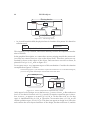
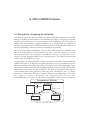
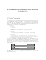
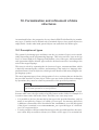
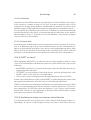
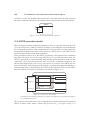
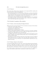
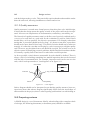
The graphical symbol for a simple HOOD object is given on figure 4-1. More sophisticated forms will be given as we encounter them in the course of this book.
Provided interface
Name of the object
Internal structure
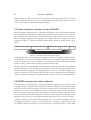
Figure 4-1 : Basic representation of a HOOD object
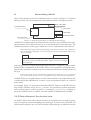
The object is represented as a container with its name on top, and a box containing the
names of the provided services (the provided interface) on the left. As mentioned
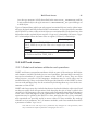
above, an object generally also requires services from other objects. These required
objects are represented as small boxes, containing only the name of the required object, that appear on the border of the object, as represented on figure 4-2. Note that
Required objects
Figure 4-2 : Required objects
only the objects are represented at this level, not the precise required interface; these
diagrams are intended to represent the global framework of the object for this level of
decomposition, not the details of the dependencies.
Some object may have special properties that are of interest to the client; in this case,
a distinctive letter appears in a box at the top left corner of the object. For example,
36
HOOD objects
some objects are active, i.e. they include their own thread(s) of control; this property
is represented with an "A" in the upper left corner, as represented on figure 4-3.
A
Name
Figure 4-3 : An active object
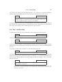
When an object appears on a diagram as a server, no internal structure is displayed.
It's only when design is focused on its implementation that the internal structure is
shown. Otherwise, the strong solid line that surrounds the object is there to remind of
its "black box" nature.
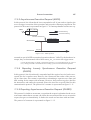
4.2.2 Detailed view: the textual description
The textual description is intended to keep as much information as possible about the
object. It includes a lot of informations that were found relevant to some projects, but
many are not useful for every project; actually, no project will need all the sections;
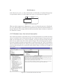
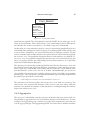
that’s why it is allowed to leave some of them empty. The textual description is therefore long, detailed, and almost impossible to read from end to end. This is a deliberate
choice: textual descriptions are easily processed by tools, allowing the designer to just
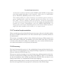
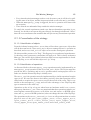
view the interesting part for a particular task at hand. Figure 4-4 shows an example of
such a tool.
Figure 4-4 : An ODS editor (Stood, from TNI)
Description of objects
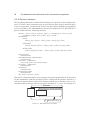
37
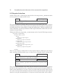
HOOD defines a fixed format for the textual description of objects. This format is
called the Object Description Skeleton, or ODS. The ODS is organized as a (possibly
quite long!) sequence of "sections", each starting with a keyword. For example, the
provided interface of an object is described in the part of the ODS that starts after the
key word PROVIDED_INTERFACE. A section may contain informal text, or formalized texts, depending on the section and how far the design has progressed.
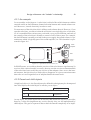
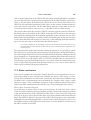
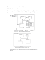
The main sections of the ODS are (see figure 4-5):
Client
Header
Implementation objects
Description
Definition of internal elements
Implementation Constraints
Behavioural implementation
Provided Interface
Behavioural definition
Implementation of operation
Implementation of operation
Implementation of operation
Implementation of operation
Required Interface
Flows
Visible part
Internals
Visibility wall
Figure 4-5 : Structure of the ODS
• A header that gives the name of the object and its kind (passive object, active class,
etc.).
• A description section which includes only informal text for the "natural language"
description of the purpose of the object.
• An implementation constraints section that describes particular conditions that
must be met by the object due to the requirements of the implementation environment, like an upper bound to the memory used by the object, for example. This
kind of constraints can be discovered at any stage of the development of the
project, from requirements analysis to coding, and must immediately be documented in this section.
• A provided interface section that describes the various services that are made
available by the object to its clients. Note that "services" may include things like
types, constants, etc. and are not restricted to only subprograms.
• A visible OBCS section that describes the (observable) behavioural properties of
the object
• A required interface section that describes the services used by this object acting
as a client. Together, the provided interface and the required interface define the
object as interfaces to the outer world.
• Several sections (data flow, exception flow) that give extra details about the services and the environment of the object; we will address these as we encounter them
later in this book.
38
HOOD objects
• An internals section that describes how the object is implemented. It includes also
several subsections that will be described later. Everything described in the internals section is behind a "visibility wall": no external module can depend on the
content of this section.
Most of these sections are mandatory. Sometimes however, a particular section may
not apply: in this case, the section is filled with the word NONE or simply omitted.
The description of the ODS given here corresponds to the latest version of HOOD (4.0). Earlier versions had slightly different headers or contents for some fields of the ODS, which are
still accepted by tools for compatibility. The reader should therefore not be surprised if some
forms not described here are found in actual, older, HOOD projects.
For example, the ODS for a simple object follows the following general structure:
OBJECT Object name is -- Header
DESCRIPTION
Informal description
IMPLEMENTATION_CONSTRAINTS
Informal description of implementation constraints (if any)
PROVIDED_INTERFACE
Formal description of the provided interface
OBJECT_CONTROL_STRUCTURE
Formal definition of behaviour
REQUIRED_INTERFACE
Formal description of the required interface
DATA_FLOWS
Formal description of data flows
EXCEPTION_FLOWS
Formal description of exception flows
INTERNALS -- Visibility wall
OBJECTS
Declaration of objects that are necessary to the implementation
(Several sections related to internal elements, not described here.)
OBJECT_CONTROL_STRUCTURE
Formal definition of the implementation of the behaviour
OPERATION_CONTROL_STRUCTURES
Formal definition of operations
END OBJECT Object name;
4.3 Design refinement: the "include" relationship
The "include" relationship, which defines objects as parents of other child objects, is
the main originality that differentiates HOOD from all other object oriented methods,
and gives the 'H' to its name - that's how the project is organized as hierarchies of objects.
Design refinement: the "include" relationship
39
4.3.1 An example
Let us consider a television set. A television is a kind of box which interacts with the
external world: an On/Off button, channel selection buttons and a sound volume control. Moreover, it needs electricity in order to work.
For most users of the television, this is all they need to know about it. However, if you
open the television, you discover that the television is no single big piece of electronics: it is assembled from various parts, each with a very precise function; and each of
the controls of the television is actually a control of one of these parts. For example,
the On/Off button is actually a switch on the power supply; the sound volume is a potentiometer which is logically part of the sound amplifier; etc. This situation is represented in figure 4-6.
Audio
amplifier
Volume
Channels
Tuner
On/Off
Power
supply
Figure 4-6 : Operations of a television set
In HOOD terms, we would say that the services of the television are implemented by
services of the various boards; externally, the user sees the services as functionalities
of the television, but actually they are services of the subparts. Once we see the internal structure, the television, as a whole object, disappears: it is just a convenient name
that refers to a well organized set of subparts that do the actual work.
4.3.2 Parent and child objects
A high level object (i.e. the first objects to be defined in a design) may be decomposed
into child objects; the initial object is called a parent object.
I-1
Definition
A parent is a module that includes at least one other module.
I-2
Definition
A child is a module which is included by a parent.
As any object, the parent object has an interface that defines the services it provides;
however, it does not implement any service directly: they are all implemented by
child objects. The goal of a parent is thus to hide the internal complexity of its imple-
40
HOOD objects
mentation. This corresponds to the notion of subsystem found in other methods: a
closed subset of a system that can be viewed externally as one single piece.
Graphically, a child object is represented inside its parent. An IMPLEMENTED_BY
arrow connects each service provided by the parent to a service of a child that implements it. Figure 4-7 gives a representation of the television using this notation.
Television set
Tuner
Select_Channel
Set_Volume
Switch_Power
Select_Channel
Audio amplifier
Set_Volume
Power supply
Switch
Figure 4-7 : HOOD representation of a television set
Note that the user sees, for example, a volume button, but the corresponding operation
is called Set_Volume. This is because the names are chosen to show services: the
button is the object, but setting the volume is the service provided by this button.
The IMPLEMENTED_BY arrow is the dotted arrow that goes from a provided operation of a parent to a provided operation of a child. For example, the Switch_Power
operation is "implemented by" the Switch operation of the Power_Supply. In
common words: the switch that appears on the television is actually a component of
some hidden part inside - the power supply. Note that the operation that implements
something may or may not have the same name as the operation being implemented.
I-6
Methodological
Each operation provided by a parent shall be implemented by
one operation provided by one of its children.
A parent is required (as opposed to simply allowed) to implement every property by
a corresponding property of a child; a parent is an empty shell whose only purpose is
to provide to clients a simplified view of the subsystem of all children. No code (nor
data) is allowed directly within a parent. If it appears that some function could be implemented directly in a parent, a special child must be created to this purpose.
This ensures that a parent is completely defined by the set of its children, with no "glue
code" at parent level. It addresses the needs of a prime contractor, who must control the interface of the parent, but delegates the development of children to subcontractors; each child
thus represents a well defined contract. This limits the integration effort by mastering the
interfaces, while leaving full freedom to subcontractors for the implementation of their part.
How many children are allowed in a parent? There is no definite answer to this question. If there are too many children, relationships between them tend to be very com-
Design refinement: the "include" relationship
41
plicated, but on the other hand, too few children will lead to spurious decomposition
levels. In practice, the following rule of thumb can be used:
Usage
A parent should be decomposed into 5 ± 2 children.
Of course, the decomposition process is not limited to one level. During the design
process, each child object will be further decomposed into more objects, and so on
until the objects are deemed simple enough to be implementable in the target language. Objects that are not decomposed are called terminal objects and correspond to
a module in the target language. Their description includes the associated code.
G-5
Definition
A terminal module is a module which has no child modules.
Conversely, the object from where the design is started, i.e. the topmost object, is
called the root object.
G-2
Definition
A module which does not have a parent is called a ROOT.
Let us finally stress an important feature of the hierarchical mechanism of HOOD. It
is often the case that a system has connections with the external world, and it is logical
to show these dependencies at the top level of decomposition. For example, it is an
important feature of the television that it features a sound volume control. However,
dealing with these connections is often a low level implementation detail. The hierarchical mechanism allows the high level object to implement the functionality by
some child, who will in turn implement it by some lower level child, and so on until
the proper abstraction level is reached. In our example, the television would transmit
Set_Volume to the electronic board, which will transmit it to the audio amplifier,
as pictured in figure 4-8 below..
This figure is for explanatory purposes; on a real HOOD diagram, you never see several
depths at the same time
Television set
Set_Volume
Electronic board
Audio amplifier
Set_Volume
Set_Volume
Figure 4-8 : Transmitting a connection to inner children
42
HOOD objects
We see that the transmission of implementation solves the contradiction between a
strong encapsulation mechanism and the need of having certain features appear in
high level specifications, while being implemented by a low level module.
4.4 Client-server and the "use" relationship
The picture of the television given in figure 4-7 does not show all the parts in the television, nor the relations between these parts. For example, the various parts use power
provided by the power supply; moreover, there is a device (not connected to the outside) that is used to amplify the video signals. In other words, some of the child objects provide services to others. We can even have child objects that implement no
property of the parent's provided interface, but that are used only internally. Figure
4-9 shows a more complete representation of the television.
Television set
Set_Volume
Video amplifier
Audio amplifier
Set_Volume
Select_Channel
Switch_Power
Tuner
Select_Channel
Provide_Video
Provide_Audio
Power supply
Switch
Provide DC
Figure 4-9 : The television set with "use" relationships
We see on this picture that the "use" relationship is represented by a bold arrow (the
USE arrow). The arrow always goes from client to server, it is not related to the direction of the flow of data. It is a very rough information, only intended to show which
objects act as servers for which clients; it does not show, for example, which service
of the server is being used by the client. This more detailed information is managed
by HOOD, but in the textual part: it would be too detailed for the graphical description. Once again, the idea is that the graphical description is only a simple, synthetic,
and general view, while the textual description holds the full information.
Note that we have added more services to some child objects, that are only needed by
their brothers, and also another child (Video amplifier) which corresponds to
no operation from the outside (parent provided operation). This demonstrates a fundamental benefit of the HOOD approach: the outside view (as seen by clients of the
Television) is simplified and reduced as compared to what actually happens inside. The parent object acts as the television box, whose purpose is to hide all the internal circuitry.
Uncles: Combining the "use" and "include" relationships
43
Finally, note that a client that uses a server does so through its provided interface, the
only thing that is visible; the client knows nothing about the strategy used by the server to provide the services, and especially it does not know whether the server is a terminal object that implements the functions directly, or a parent whose services are
implemented by children. This means that changing the strategy used by the server
will never affect the clients. It is perfectly allowable (and actually recommended) to
start with a prototype implementation of the server as a terminal object, and once the
behaviour is validated, provide an actual implementation by further refining it into
children.
4.5 Uncles: Combining the "use" and "include" relationships
4.5.1 Uncles
Consider the situation depicted on figure 4-10. This describes the first level of decomposition of a robot arm used for painting cars. We see that the robot includes two main
parts, the physical arm and the driving device. Obviously, the driving device uses the
physical arm.
Painting robot
Driving device
Paint
Paint
Physical arm
Move
Figure 4-10 : A painting robot.
Consider now what happens at the next level of decomposition. If we analyse the driving device, we'll split it into a trajectory tracking system that will be in charge of computing and controlling the movements of the arm in space, a movement data base that
will hold the data corresponding to basic movements, and a controller that will fetch
the data from the data base and use them to drive the tracking system (figure 4-11).
The interesting point in that example is that the driving device as a whole uses the
physical arm, but actually, when decomposed, we see that only one of its children requires it: the tracking system. To summarize the situation:
• The driving device uses a brother, the physical arm. The physical arm is part of the
required interface of the driving device.
• Since the driving device is not a terminal object, it is only an empty shell. There
must be some child (the tracking system, see figure 4-11) that actually requires access to the physical arm.
44
HOOD objects
Driving device
Controller
Paint
Paint
Tracking System
Data Base
Physical arm
Figure 4-11 : The driving device.
• As viewed from this child, the physical arm is a brother of its parent. It is therefore
called an uncle.
U-3
Definition
An uncle of a child module is a module used by its parent.
This situation is very common, and results naturally from the decomposition mechanism of HOOD.
In the graphical description, we cannot have arrows pointing outside the current object (since we want to focus our view on the object itself). Therefore, uncles are represented by boxes at the edges of the object, and USE arrow can refer to them, as
pictured for Physical_Arm on figure 4-11.
Let us stress now a very important aspect of this mechanism. Consider the situation
exemplified on figure 4-12 below.
The following figure is just intended to explain the mechanism. On a real HOOD diagram,
you never see global relationships and internals at the same time.
Parent_A
Child_A
Parent_B
Oper
Parent_B
Child_B
Oper
Figure 4-12 : Uncles and operations implemented by a child
At the upper level of design, we see that Parent_A uses Parent_B. But at the next
level, we see that it is because Child_A needs it (it requires operation Oper); therefore, Parent_B appears as an uncle of Child_A. On the other side, we see that
Oper is implemented by Child_B. Therefore, at execution time, Child_A will
call the operation Oper of Child_B. This does not appear at design level, since the
tools enforce the strict layered structure of the design, but the tools know it, and the
Uncles: Combining the "use" and "include" relationships
45
generated code will result in a direct call to the actual eventual operation. In other
words, the layered design structure does not end up in useless calls of subprograms
that will just call other subprograms. There is no efficiency penalty in the generated
code for the design structure. The parent-child implementation model solves the contradiction between avoiding excessive nesting levels at run-time, and excessive complexity in the design. This important property is not shared by many other design
methods, and is a very positive effect of using HOOD, since the designers are not discouraged from a rigorous design by efficiency considerations.
If the target language is Ada, renaming declarations can be used to keep a code structure that
matches the design structure for traceability reasons. If the target language is C++, the same
effect can be achieved with macros or inlined functions. See the code generation rules in
section 17 which describe implementation techniques.
4.5.2 Environment
Sometimes, a deep-level child needs the services of an object representing, for example, some reusable module, like a graphic or mathematical library. Since this library
is not part of the current design, it should appear as a top-level, separate, hierarchy.
Normal HOOD rules require that a module used by a child be also marked as being
used by its parent, since the child is part of the parent. If we follow strictly this rule,
the library should be part of the required interface of every parent, up to the top-level
one. This would clutter up the graphical description with a lot of uncles that are not
really interesting from the point of view of the logical structure.
To avoid this, root objects from a different hierarchy are called environment, and are
allowed to only appear at the decomposition level where they add significant information. In a sense, they are implicitly uncles of any object, without being part of the
required interface of the parent. Because of this special property, they are marked
with an "E" in the left part of the box.
Graphical_Interface
E
X-Window
Figure 4-13 : Using an environment object
On the example of figure 4-13, objects inside Graphical_Interface may refer
to object X_Window even if the parent object of Graphical_Interface does
not refer to it.
Once introduced, environment are normally propagated to all lower levels. In other
words, environment objects are allowed to enter the design tree by a "back door", at
a level where they become significant. But once entered, they stay like any uncle. This
46
HOOD objects
avoids adding too much complexity to the diagram, for those objects which are not
part of the software to be developed explicitly.
The notion of environment is very handy for representing the components that escape
the normal hierarchical design, because they are used at any design levels. It is sometimes called "software buses" ([Rosen95-2]), by analogy with power buses in electronics, that can be used at any level irrespective of the logical structure. For example,
the television requires power from the power plant. The power plant is therefore part
of the required interface of the television, but it is clearly something "external" to the
design of the television itself. It should appear as an environment object.
4.6 Other design issues
4.6.1 Splitting operations: OP_Controls
Sometimes, a provided operation of a parent does not match exactly one operation of
one child, but rather a sequence of operations from one or several children. For example, an active object generally features a Start operation to initiate its activity. If the
object is decomposed into several active children, its Start operation should call the
Start operations of every child.
It would be tempting to have a procedure in the parent that simply calls the various
operations, but this would break the principle that a parent object has no operation of
its own. The operation could also be added to any child, but this would be a poor design, since it would not be logically related to the object that hosts it. Therefore, an
intermediate module has to be introduced. However, it is not a full "object" in the
sense that it does not correspond to any real-world object, nor has it the properties of
an abstract state machine. It is rather an object reduced to a single functional abstraction, just here to express a sequence of actions. Since it is quite special, HOOD introduces a special kind of object for it: it is called an OPeration control (OP_Control).
G-7
Definition
An OP-Control is a terminal module without internal data dedicated to the implementation of one and only one operation.
An OP_Control appears as a child of the parent, and must correspond to an
IMPLEMENTED_BY arrow. It is represented as a simplified object, as on figure
4-14. Note that there is no provided interface: only the operation name is significant.
Operation_Name
Figure 4-14 : Representation of an OP_Control
Other design issues
47
An OP_Control appears normally on the diagram, and USE arrows show which objects provide the operations being called. The example of the active object with
Start operations would appear as on figure 4-15.
A
Parent_Object
A
Start_All
Child_1
Start
Start
A
A
Child_3
Start
Child_2
Start
Figure 4-15 : Using an OP_Control
In practice, OP_Controls are seldom used; as soon as things get a bit complicated, it
is better to provide a full-fledged object.
4.6.2 Grouping operations: operation sets
Sometimes, an object provides a set of operations that are logically related. For example, an iterator used to provide a walk through a data structure features an initialization operation, a way of getting an element and skipping to the next one, and an
operation to check for the end of the structure. Applied to a file, this would correspond
to the Open, Get and End_Of_File operations.
It would be possible to simply mention these operations in the provided interface of
the object. However, this would not show the logical connection between the operations, and could lead to too many operations in the provided interface. For these reasons, such operations can be grouped into an operation set. An operation set has a
name of its own and appears as only one element in the graphical description of the
object. To differentiate it from an single operation, the name of the operation set appears within curly brackets, as shown on figure 4-16. Note that the object may provide
other operations, not included in the operation set.
Data_Structure
Add_Element
Retrieve_Element
{Iterator}
Figure 4-16 : An object with an operation set
An operation set may include other operation sets, but nothing else than operations
and operation sets. This ensures that eventually only operations are provided; but the
operation sets provide a convenient way of building a tree of operation groupings.
48
HOOD objects
On most tools, it is possible to represent operation sets in "open" or "closed" representation. In the latter, only the name is displayed (as in figure 4-16) while in the
former, the components of the operation sets are displayed. This allows the designer
to see the level of details which is appropriate to his/her concerns at the moment. The
same object in "open" representation appears on figure 4-17.
Data_Structure
Add_Element
Retrieve_Element
{Iterator
Get_First
Get_Next
Is_Exhausted
}
Figure 4-17 : An object with an open operation set
4.6.3 Sequential or concurrent execution: active objects
Normally, an operation is executed sequentially by the caller thread. Alternatively,
the operation may be executed by another thread of control on behalf of the caller, allowing concurrent execution of the client and the service. This is an important property, since it requires a cooperation between the threads involved: a protocol.
HOOD offers various communication protocols that will be detailed in section 11.4.
For this reason, operations that are not executed sequentially are marked with a little
"trigger" arrow, and an object that provides such operations is marked with an 'A' (for
active). Other objects are said to be passive. It must be stressed that an active object
is not simply the representation of a thread, but an object whose operations may influence the temporal behaviour (through scheduling, etc.) of the caller. At implementation level, active objects use tasks, processes, or threads, as provided by the
language or operating system, but an active object is a higher level notion: for example, one HOOD object may correspond to several cooperating threads of control.
4.7 Summary
HOOD objects are basic design units, based on a client-server model. An object is either terminal or decomposed into child objects. A parent object is an empty shell
whose purpose is to hide the implementation and lower the complexity of the design.
Objects use each others, and the "use" relationships is traced across all design level.
An object that is used by the parent of a child is called an uncle, while a root object
that can enter the design at any point is called an environment object.
Special objects used for functional modelling are called OP_Controls. Logically related operations can be grouped into operation sets. Objects may be active or passive.
5. Data modelling in HOOD
HOOD makes a clear difference between objects and data. Objects provide procedural services, while data are informations exchanged between objects by these services.
Other design methods have taken the opposite view: everything is an object, as an instance of some defining class. This provides for a unification of concepts, a simplification from a theoretical point of view, but unification can easily lead to confusion.
HOOD’s choice is rather to separate concerns; separating data analysis from structural and functional analysis reduces the complexity that has to be dealt with .
5.1 Data flows
In the previous chapter, we saw that the graphical description tells which objects are
clients of which servers. However, this is not sufficient to understand the relationships between client and server, because most of the time they exchange data (the parameters of the provided operations), which are part of the purpose of the server.
The flow of data is documented on the graphical description with data flow arrows,
which are small arrows in the direction of the data flow: towards the server (in the direction of the USE arrow) if the data is consumed by the server, from the server if the
data is produced by the server. A double arrow is used for data that transit both ways
between the server and the client.
A double arrow may correspond to data that is modified by the server and returned to the
client in one operation, or to data provided to the server in one operation and returned to the
client in another one. It shows the flow of data between objects, not individual operations.
Automatic Teller
Card_Data
Read_Card
User Interface
Data Base
Read_Card
Dispense_Cash
Commands
Cash
Messages
Controller
Dispense_Cash
Account balance
Data_Blocks
E
Figure 5-1 : Data flows
File_System
50
Data modelling in HOOD
Each data flow arrow is documented with a name, an informal text which abstracts
the information exchanged between the objects. Those arrows are put along the USE
(or IMPLEMENTED_BY) arrow, as pictured on figure 5-1.
This example shows the general organization of an automatic teller machine. The
Controller sends messages to the User_Interface, and gets commands from
it. It uses the customer Data_Base to update the account balance. The Data_Base
exchanges informations in the form of data blocks with the File_System, an environment object.
Note that this figure does not show which operation of the user interface is used to
send commands. It represents major data flows between objects, and is not intended
to show the precise flows for each operation. Actually, it would be an error to try and
show all parameters that are exchanged by the various provided operations. The
graphical interface just shows flows that are useful for the understanding of the architecture. Of course, a complete description of all data flows is a very important documentation, but like any detailed description, it is kept in the textual description.
5.2 HOOD types
Every data in HOOD must be typed. A HOOD type defines the properties of data and
parameters exchanged between objects, such as the set of values that belong to the
type and the set of operations that can be applied to the data.
A type is recognized by its name, and data declared with different type names are different in nature, even if at machine level these types are represented identically, or
with compatible machine types. This principle is called strong typing.
Although programming languages have various levels of typing, at design level, the
focus is on the description of logical properties, not machine implementation. Therefore, strong typing must be applied, even if the target language is not strongly typed.
In this case, the high level types of design will be implemented with the lower level
types of the language, but the strong typing must be preserved at design level.
There is a hierarchy of types, according to their dependence to the target language and
their degree of generality:
• Basic types.
• Abstract data types
• Classes
5.3 Basic types
Basic types are types whose value set and operations are entirely defined by the underlying language. Basic types can be predefined or user defined.
Abstract data types
51
A predefined type is a type which is part of the definition of the language. They include predefined integer types (like Integer, Int, etc.), floating point types, fixed point
types, boolean types... Such types vary not only with the language, but also with the
machine, and sometimes with the compiler, even for the same language on the same
machine. They suffer inherently from portability problems, but there is also a higher
level issue: they do not belong to the problem domain. For example, it makes no sense
to add a length to a voltage. If they are both represented as FLOAT, no consistency
check can find such nonsense. So, it is generally better to avoid predefined types.
A user defined type is a type whose definition is provided by the user. It has at least
a name that makes it different from other types. In the previous example, a LENGTH
type can be defined that would be different from a VOLTAGE type. Both types can be
implemented by a predefined type, but at design level, they are different types, thus
improving possible consistency checks. Some languages (like Ada) can enforce that
kind of strong typing for user defined types, while others (C, FORTRAN) cannot.
The properties of basic types (set of values, operations) are defined by the rules of the
target language. For example, the following (Ada) definition:
type Counter is range 1..1000;
defines an integer type whose values are integer numbers in the range from 1 to 1000
(independently of any machine representation), with the usual arithmetical operations. On the other hand, the following (C) definition:
typedef int Counter;
defines an integer type of target-dependent range, with the usual arithmetical operations plus logical operations such as "shift", "and", "or", etc.
5.4 Abstract data types
Basic types are still very elementary. It is often useful to define more evolved data
types, whose precise implementation is hidden and that can be accessed only by operations representing a well defined interface. Since the properties of these types are
not linked to any concrete implementation, they are called abstract data types.
Abstract data types are convenient for describing entities of the problem domain.
Since such types involve some structuring, as well as the definition of their behaviour,
the data structure requires an analysis, and can be thought of as being made of various
semantically important parts.
5.4.1 Introduction
HOOD provides a special construct to describe abstract data types, as a special kind
of object, called a HOOD Abstract Data Type (HADT). It is represented like a regular
52
Data modelling in HOOD
object, but with square instead of rounded corners, as shown on figure 5-2. Abstract
data type uncles (or environments) are represented as uncles with square corners.
Name of the HADT
Provided interface
Uncle object
Uncle HADT
E
Environment HADT
Internal structure
Figure 5-2 : Graphical representation of a HOOD abstract data type.
An HADT is an object whose provided interface exports a type, called the main type,
and operations, all of which accept one or several parameters of the main type. The
mandatory parameter of the type is called the receiver, and must have the name me.
Depending on the target programming language, there will be an explicit "me" parameter in
the corresponding subprogram, or it will correspond to the implicit parameter called "self",
"this" or "current".
G-8
Definition
An abstract data type is an object which provides one and
only one main type and operations whose receiver is of type
the main type.
Only the type name is exported; the actual type structure is completely hidden, and is
defined in the INTERNALS of the HADT. Since it is not possible to modify the structure directly, operations (called constructors) must be provided to construct values of
the type.
From a client point of view, the HADT is assimilated to its main type, i.e. it is used like a
type, but the object structure serves to encapsulate the type with its associated operations.
An HADT object is a regular object; it can be either terminal, or decomposed into other child objects that implement it. It can be a root (environment) object, or a child of
some parent.
For example, figure 5-3 represents a fruit basket HADT. Since it is an HADT, the user
may declare variables of type Fruit_Basket. It is possible to perform operations
such as Add_Apple, Remove_Melon, or Number_Of_Fruits, to change or
query the content of such a variable; how this variable is implemented is hidden.
5.4.2 Data refinement: the structure view
An HADT differs from other objects because its operations do not stand by themselves, but operate on data belonging to the main type. In order to use an HADT, the
client must first declare one or several variables of the main type to which the various
Abstract data types
53
Fruit_Basket
Add_Apple
Remove_Apple
Number_of_Apples
Add_Melon
Remove_Melon
Number_of_Melons
Number_of_Fruits
Figure 5-3 : A fruit basket HADT
operations are applied. The client therefore uses the HADT for its main type, not directly for its operations. This is still clearly a "use" relationship, but of a different nature than the one we have seen before: it is called a "type-use" relationship.
At this point, it is clear that there must be a way of representing graphically this new
relationship. But putting new kinds of arrows on existing graphs would quickly lead
to an excessive complexity. As usual, HOOD prefers to separate concerns. For this
reason, relations between data structures are represented on a different kind of graph:
the structure view. The graphical description that we used until now is called the client-server view. It is possible to display the structure view of every kind of object, but
since it is used to describe the relationships between data structures, it is especially
useful for HOOD abstract data types.
The structure view shows the parent and child objects like the client-server view, but
the relations between the objects are different. A USE arrow in the structure view denotes a "type-use" relationship, which shows that the client uses a type defined in the
provided interface of the server for one of its data. IMPLEMENTED_BY arrows are
also possible on a structure view, but they always go from a provided type to another
provided type. They mean that a provided abstract data type is actually implemented
by another type provided by some child.
A full example of a structure view will be detailed in section 5.6.
The structure view does not replace the client-server view: both are necessary. The
client-server view expresses the structure of the services (who uses what), while the
structure view depicts the structure of the data that are exchanged along the relationships of the client-server view.
5.4.3 Aggregation
The "type-use" relationship is not the only way an abstract data type can be used: it is
also possible to aggregate one or several abstract data types into another one. To state
it simply, the aggregating type is made of several parts (components), and each part
is of an aggregated type. The aggregating HADT is a client, since it includes elements
54
Data modelling in HOOD
provided by other (server) HADT. This relation is represented on the structure view
with an AGGREGATION arrow, as represented on figure 5-4.
Name
Figure 5-4 : Aggregation arrow
An AGGREGATION arrow joins the aggregating type to the aggregated type. The arrow is labelled with the name of the component in the aggregating type. Such components are called attributes, they are part of each instance of the type. Since an
HADT can be non terminal, aggregated HADT may be children, as well as uncles, of
the aggregating HADT.
Note that AGGREGATION arrows show the major aggregations, there is no obligation
to have one for each component of the underlying structure. If components are basic
types, there is no HADT to point to, and there cannot be any arrow to represent them.
The "aggregate" relationship should not be confused with the "type-use" relationship described before. A "type-use" relationship means that the client declares variables of a type
provided by the server; it is a relation from data (type instance) to type. On the other hand,
the "aggregate" relationship means that a type is built from other types: it is a relation from
type to type. This is why it is necessary to provide a different kind of arrow for aggregation.
5.5 Classes
5.5.1 Introduction
Sometimes, different types share some common properties. In such cases, code sharing for common behaviours can be obtained through inheritance. Inheritance is a
powerful tool, but it may increase the complexity of the design, and has to be controlled. Therefore, HOOD defines a special kind of HADT, called a class, for which
inheritance is allowed. Only classes may use inheritance.
A class is represented like a regular HADT, with a "C" in the upper left corner. The
same notation applies naturally to uncle classes also, as represented on figure 5-5.
Provided interface
C
Name of the class
Uncle object
Uncle HADT
C
Internal structure
Figure 5-5 : Representation of a class.
Uncle class
Classes
55
5.5.2 Inheritance
As any abstract data type, a class may be defined and refined by aggregation, describing how they are assembled from other components; in addition, they can use inheritance, expressing that the new class is an extension of an existing class. Inheritance
is represented on the structure view with an arrow whose form is given on figure 5-6.
An inheritance arrow joins a subclass to its superclass.
Figure 5-6 : Inheritance arrow
Inheritance in HOOD has its conventional meaning: the subclass gets the data structure and the operations of its superclass. Details of the inheritance mechanism (especially whether and how multiple inheritance is allowed) are left to the target language;
the reasons for this are:
• Languages differ in their views of inheritance, and imposing a particular mechanism would lead either to not benefiting from all possibilities of the target language
(if too restrictive), or inefficient implementations (if too liberal).
• Inheritance is not a driving aspect of HOOD; it appears only at the level of the
leaves of the design tree, as a convenience when useful. There is therefore no structural issue involved when a design is used with different languages.
A class may inherit from one or several (if multiple inheritance is acceptable) classes,
which may themselves inherit from other classes. Inheritance therefore defines, in itself, a tree structure (or to be mathematically correct, a lattice in the general case).
Combining two independent tree structures would quickly lead to an excessive complexity. Therefore, when inheritance is used, it is necessary to forbid any further parent-child decomposition at the same time.
I-14
A class shall be terminal.
Methodological
On the other hand, a class may be a root, or a child of another object. Whether a class
should be a child or an environment is a design decision. A child appears naturally
when a class is only used for the implementation of the enclosing object, while a reusable class appears as an environment that will be available to the whole project.
As a class is an HADT, it can also aggregate other HADT, or even classes. However, since
a class is terminal, the aggregated HADT must be external to the class. It is important not
to confuse aggregation, which describes (visibly) a data structure as gathering several other
structures, with parent-child decomposition, which is an internal (and hidden) structuring.
56
Data modelling in HOOD
5.6 Example
In this example1, we show how we can model a company as an abstract data type. The
object provides a number of services, some of which are related to the company itself
(for example providing the gross income), while others are related to the employees,
i.e. the people who work for the company (for example, whether a given employee
previously worked for some other company). In a real project, there would be many
such operations, but we'll show only one of each for the sake of the example.
The structure view of the company represented on figure 5-8 describes our model of
the company, while the client-server view on figure 5-7 shows the provided services..
General_Company
Company
Gross_Income
Worked_For
Gross_Income
Employee
Employee_List : List
{List_Operations}
C
Employee
Worked_For
Company
C
Company_List : List
Person
{List_Operations}
Name
Address
Figure 5-7 : Client-server view of the company
General_Company
Company
Company
Employee
Company
Employee_List : List
List
C
Employee
Employee
C
Person
Company_List : List
Person
List
Figure 5-8 : Structure view of the company.
1. This example is derived, with permission, from the example presented in [Canals97]
Summary
57
We see a module, General_Company which provides two types, Company which
represents the company itself, and Employee which represents the employees working for the company. These types are implemented by corresponding child modules.
The company aggregates a list of its employees (the list itself is provided by a generic
module, as described in the next chapter), and similarly an employee aggregates a list
of the companies he/she worked for. Note that each of these lists "type-use" the type
of their components (black arrows), i.e. a list of employees has to make use of the type
Employee itself, and conversely for the list of companies.
Employee is represented as a class rather than a simple HADT, since we expect to
have various kinds of employees that will share common properties. It inherits from
the class Person, which represents the characteristics of a person in general (whether an employee or not). This shows that an employee is a kind of person.
The client-server view shows that the services offered are implemented by the corresponding child modules. We see also that the class Employee uses operations from
Person, and that each of Company and Employee modules uses operations from
the corresponding list types (OP_USE arrows).
5.7 Summary
HOOD clearly separates data analysis from functional analysis. The main concern is
for data exchanged between objects, represented with data flows.
Every data is typed. HOOD recognizes basic types, which represent the elementary
types of the programming languages; abstract data types, whose internals are hidden
and that can be accessed only through their provided operations; and classes, which
are abstract data types that can inherit from one another, but cannot be further decomposed into child objects.
6. Other HOOD features
6.1 Exceptions: designing for reliability
A reliable system is one that can produce an appropriate behaviour under any circumstances, including unexpected ones. An important principle for the design of reliable
systems is mutual distrust: if a server requires some conditions to be obeyed by its
callers (like not providing a negative argument to a Log function for example), it
should not assume that the condition will always be met: it should rather check it, to
avoid transforming a small error into a potentially huge problem.
However this principle immediately raises an issue: what to do if the condition is not
met? It is not possible to return normally to the caller, since the required service has
not been performed. There must be a mechanism to specify an abnormal return,
which is clearly distinguishable from a normal return. The HOOD element that
achieves this is called an exception.
An exception is an entity which has a name, and can be declared by objects (including
HADTs and classes), in the same way that they declare types or operations. It specifies the potentiality of an abnormal return of control (to the client) during the execution of an operation. When the corresponding situation is detected, control flows back
immediately to the client in order to notify it. The flow of exception is thus opposite
to the normal control flow and this is shown by a line crossing the "use" or "implemented-by" relationships. This line is marked with the exception name(s). For examp l e , f i g u r e 6 -1 s h o w s a d i a g r a m w i t h e x c e pt i o n f l o ws o n US E a nd
IMPLEMENTED_BY arrows. It represents a temperature monitor that gets tempera-
Temperature_Monitor
Monitor_Failure
Get_Value
Acquisition
Get_Value
Sensor_Failure
Sensor_1
Get_Value
Sensor_Failure
Sensor_2
Get_Value
Figure 6-1 : Exception flows
Generics: designing for reuse
59
ture from two sensors. If any sensor fails, it gets the value from the other one. If however both sensors fail, then the monitor as a whole reports failure
The last issue with exceptions is how to handle them: what should the client do in the
case of such an abnormal return? It is up to the client to define it, but some response
must be defined; otherwise, the exception may propagate to other levels that were not
supposed to receive it, and the correct behaviour of the program will be at risk. This
is why exceptions appear so prominently on the graphical description. Moreover,
HOOD rules (that will be developed in section 9.3.2) ensure that when a client calls
an operation that may raise an exception, it must define what happens to it.
6.2 Generics: designing for reuse
6.2.1 Generic definition
A generic object is a representation of a pattern of objects which can be reused and
parameterized by types (including HADT and classes), constants and operations.
These parameters define the formal parameters of the generic object.
R-9
Methodological
The formal parameters of a generic can only be types, constants or operations.
Generics are only allowed as root objects (they cannot be children of another object);
on the other hand, they may use freely siblings or other environment objects.
Generics cannot be child objects because they cannot actually provide services; they are just
models. Only instances of generics (see below) can.
A generic appears on the graphical representation as an object (including HADT or
class) with a special uncle named "Formal_Parameters", identified by an "F", which
holds the definition of the formal parameters. Figure 6-2 represents a generic unit.
Generic_List
Add_Last
Get_First
F Formal parameters
Figure 6-2 : A generic list
A generic is either terminal, or decomposed further into child objects, as usual. The
formal parameters are really considered as an uncle; when a child of the generic requires a formal parameter, a USE arrow has to be drawn towards the formal parame-
60
Other HOOD features
ters box. If the children of a generic are further decomposed, they must include the
formal parameters of their parent in their required interface, as for any uncle.
A generic object (or a non generic object) cannot have a generic child, since a generic is always a root object. Note that this rules is more restrictive than the rules for the equivalent
structure (C++ templates or Ada generics) of the target languages. On the other hand, nothing prevents a generic from including a child that is an instance of a generic, i.e. a regular
object built after the template.
6.2.2 Generic instantiation
An instance of a generic is a regular object, obtained from the generic by providing
actual values to the generic formal parameters. These parameters must be provided by
objects that are directly visible from the instantiation location; they may be supplied
by environment objects, or siblings. As always, checks are performed to ensure that
the actual parameters match the types of the formal ones.
Single instance
An instance can be either a child object inside some parent or a root (environment)
object. Since an instance is a normal module, there is no special representation for it.
However, its name must be followed by the generic name (in the header of the graphical description) to remind the reader that the object is an instance: the name is "typed"
with the name of the generic object. For example, a list of measure points would be
represented as on figure 6-3.
Measure_Points_List : Generic_List
Add_Last
Get_First
Figure 6-3 : Instance of a generic
Multiple instances
Sometimes, generics are used to provide a set of identical (modulo some parameterization) objects. For example, a plane with four engines requires one object to represent each of its engines; but since the engines are identical, it is better to design them
only once as a generic, and then make four instantiations.
To show these similarities, the representation of several identical generic instances is
a double shaped object or class with an indexed generic name "typed" with the name
of the generic object. The names of the instances are generated as the generic name
concatenated with the successive integer values of the index range. Figure 6-4 shows
how the airplane's engines would be represented.
Virtual nodes: designing with distribution
61
Engine[1..4]: Generic_Engine
Start
Stop
Set_Thrust
Figure 6-4 : Similar instantiations for the engines of an airplane
Generic_Engine is the name of a generic; the airplane has four similar engines,
named Engine[1], Engine[2], etc. The objects (instances) are independent, but
each has the same operations Start, Stop and Set_Thrust.
Since instances are made after a generic model, they have exactly the same interface
as the model. The provided interface is a copy of the generic one (this is done automatically by the tool when an instance is declared) and is normally represented on the
graphical description. On the other hand, although an instance inherits the full environment (required interface) of the generic, this imported interface is not shown in the
graphical description. This is because the required interface is only a concern to the
designers who deal with the generic, not to those who will use the instance.
Dragging in the whole required interface of a generic would require including objects used
by the generic into the required interface of the parent of the instantiation. It would clutter
the design with irrelevant information, since the generic itself should be seen as a black box.
Note that multiple instances of a generic, whether obtained by several instantiations
or by one multiple instantiation, are identical. Therefore it makes sense to have multiple instances only if there is some hidden internal state that can vary over time independently in each of the instances, either because there are global state variables, or
because the object is active. Otherwise, calling a service provided by any instance
would be strictly equivalent to calling the same service provided by another instance.
6.3 Virtual nodes: designing with distribution
HOOD has been designed with a great concern for distribution. This means that it allows the design of distributed systems without letting the distribution aspects clutter
the whole design. It does it in the usual way: by separating concerns and isolating issues. Three independent views are important in a distributed system:
• the logical space view, consisting of a set of design trees. This is a set of software
modules and is what we have been dealing with until now.
• a distribution space view, which deals with the definition of indivisible units of
distribution, but still as logical entities. This will be the main object of this section.
• a physical node space view, which deals with the definition of physical nodes by
configuration of distribution units. This is the available hardware.
62
Other HOOD features
The distribution space is modeled as a hierarchy of virtual nodes. They are called
nodes because they could be units of distribution, but they are virtual nodes because
they do not necessarily correspond to the physical nodes. Actually, several virtual
nodes can be implemented on a single physical node.
A virtual node is represented as an object, with a "V" in the upper left corner, as represented on figure 6-5.
V
Figure 6-5 : representation of a virtual node
A virtual node is represented as an object with a provided interface, although it is generally
empty. The reason is that this provided interface can be used to specify communication protocols, and other implementation details when they are not automatically taken in charge of
by the tools. Similarly, virtual nodes can have USE arrows between them. Using these facilities is beyond the scope of this book.
A virtual node is either terminal (and corresponds to an executable if implemented by
software), or decomposed into child virtual nodes (system level), therefore defining a
tree of virtual nodes. In simple cases, this tree may be only two levels deep: level 1
represents the whole system, and level 2 the various servers. However, it may be more
convenient to define more levels. For example, an airplane may be divided into a passenger subsystem, a control subsystem, and a flight subsystem. Each of these may (or
not) be divided into more subsystems, as pictured on figure 6-6.
Airplane
V
V
V Passengers
Passengers
V
V
Flight
V
Individual_Comfort
Control
V Public_Address
V
Flight
V Auto-pilot
V
Radio
V Engines
Figure 6-6 : VN description of an airplane
Note that this decomposition means that the passenger subsystem and the flight subsystem are considered independent enough to form different (but possibly still communicating) entities. It does not require them to be on different computers, they could
Summary
63
all be implemented as subprocesses of a global centralized big computer (although
this would obviously not be desirable!).
The previous partitioning was related to the logical structure of the project; it is not
necessarily the case. For example, if it is expected that a system will involve several
local networks, connected by a wide area network, it could be appropriate to describe
the hierarchy of networks as a hierarchy of virtual nodes, as pictured on figure 6-7.
V
Company IS
V Gerrnan branch
V
UK branch
V
French branch
V Marseille branch
V French branch
V Toulouse branch
V
Paris branch
etc...
Figure 6-7 : A hierarchy of networks
Once again, this describes a logical structure of the system, there is no commitment
to which parts of the software will run on which virtual node - and no commitment to
a physical structure. For example, the Toulouse branch may run its programs on a machine which is physically in Paris, and also running the "Paris branch" virtual node.
A final note: the notion of virtual node is very handy to include in a design a representation of aspects that are not related to computers, like human operators, mechanical devices, etc.
6.4 Summary
Exceptions are the way to signal a client that the desired service could not be completed by the server.
Generics allow to make several similar objects (generic instances) from a common
template. Formal generic parameters allow the instance to be parametered.
Virtual nodes provide a logical view of the distribution of a system that decouples it
from any physical decomposition.
7. A design example
In this chapter, we show an example of a HOOD design. The reader is in the position
of a project reviewer, i.e. we will present the structure of a project without explaining
how it was obtained. The goal is to present how the HOOD "language" can be used
to describe an existing project; the process that is used to design a project is of course
extremely important, but it will be addressed later, in the third part of this book.
7.1 Introduction
This example shows the structure of an Electronic Mailing System (EMS). The system allows various people on a network to communicate by electronic mail. It is intended to work under a windowing environment, such as X-Window, with a nice user
interface. Each user may send letters to other users, receive letters, reply, etc. There
is a centralized data base of users, which is managed by an administrator. Only the
administrator is allowed to add or remove users in the data base. Various parameters,
such as window appearance, automatic text in messages, etc. can be configured.
7.2 General structure of the Electronic Mailing System
Figure 7-1 presents the client-server view of the first decomposition level of the EMS,
and figure 7-2 presents its structure view. Note that at this point, it is really a system
view: although it is designed as one HOOD object, it involves several programs.
The provided operations of the whole system are Boot, which represents the actions
that are necessary to start the EMS when the computer is turned on, ems which represents the call by a user of the program that allows to send or receive messages, and
a number of operations (represented here as an operation set, GUI_Call_Backs),
that represent the call-backs issued by the OS following user interactions. Since the
origin of the events (like mouse-clicks) is external to the system, we must represent
the functions that are called in the provided interface. Note that this operation set is
represented here in "open" state: we see that it includes three other operation sets, corresponding to various screens: the Mail_Tool_Call_Backs set for the regular
mail tool screen, the Administration_Call_Backs for the administrator’s
screens, and the Configuration_Call_Backs for the screens dealing with personal customizing. These operations sets are not open here, since the precise defini-
General structure of the Electronic Mailing System
65
Figure 7-1 : Client-Server view of the EMS
Figure 7-2 : Structure view of the EMS
tion of the call-backs is irrelevant for the current level of details. GUI_Call_Backs
also includes an exit_ems operation which is the call-back to stop the program.
Internally, the system is decomposed into several children. We have decided here to
separate the user interface from the various functions to be performed. We have therefore a GUI object which implements all user accessible functions, which constructs
the various requests, and then uses the specialized objects to effectively execute the
various functions. Administration is in charge of managing the user data base
(with operations Add_User, Delete_User, and Change_User), Configu-
66
A design example
ration is in charge of managing user preferences (with operations Store, Retrieve, and Default_Settings), and Mail_Tool is in charge of actually
sending and receiving the letters (with operations Read, Write, and Reply). We
note the kind of data exchanged between the GUI and the various servers along the
corresponding USE arrows (T_Directory_Data, T_Configuration_Data,
and T_Letters), as well as the fact that Configuration may raise the
Unauthorized_User exception if someone who has not the administrator’s privileges is attempting some operation.
The Mail_Tool is the interesting part. It is in charge of transforming T_Letters
(i.e. the high level notion, as viewed by the user) into T_Messages (i.e. the things
that are exchanged over the network). This may involve adding headers, encoding the
letter, etc. Those messages are put into a Buffer (with operations Put_Message,
Get_Message, and Size) that serves as a temporary storage for the messages. A
Mail_Server object is in charge of picking up the messages from the buffer and
sending them to the Network (represented as an environment object that will include
OS functions to access the network), and also getting the messages from the network
and depositing them into the Buffer. Since Mail_Server implements the Boot
operation, we see that it is started when the system is started.
The T_Messages play an important role; they are the basic data exchanged between
the Mail_Tool and the network. They have to be created by an object, but are destroyed by another object. This calls for making them an independent module, but of
course since T_Messages is actually a data exchanged through operations, this will
be an HADT (with operations Create and Delete). If it is later discovered that
there are actually several kinds of messages, the HADT may well evolve into a class.
The same remark applies to the type T_Letters.
We note on the client-server view (figure 7-1) that there is no USE arrow from Buffer to the HADT T_Messages: this shows that Buffer does not create nor delete
any message. On the other hand, since messages are parameters of Buffer operations, this arrow does appear on the structure view, as represented on figure 7-2.
We note also on this figure that T_Messages aggregates T_Letters, since messages contain (among other things) the letter itself.
7.3 Structure of the GUI
We won’t detail here all the components of the EMS, but we’ll go into more details
for the GUI object to show an example of structural refinement. The client-server
view of the GUI is represented on figure 7-3, and it structure view on figure 7-4.
Quite naturally, each of the operation sets is implemented by a dedicated child:
Configuration_GUI, Administration_GUI, and Mail_GUI. Note that in
general, most of the code for these modules will be generated with an User Interface
Structure of the GUI
67
Figure 7-3 : Client-Server view of the GUI
Figure 7-4 : Structure view of the GUI
Management System (UIMS). In addition, there must be a kind of "driver" to draw
the initial screen and also terminate the system. This is done by the Main_Screen
object, which implements the operations Run and End_Run. Each of the GUI objects also features a (non exported) Activate operation: when called, it will draw
the corresponding screen and activate the associated call-back. On the other hand,
there is no provided function to deactivate the screen, since this will happen from a
68
A design example
user click on a "Quit" button in the corresponding screen, and is therefore internal to
the object.
We also discover an object which is purely internal, the On_Line_Help. It is in
charge of managing help windows. Help contexts are described as a data type which
is exported by On_Line_Help, as can be seen on the structure view on figure 7-4.
7.4 Distribution
We can now decide how to split the various parts of the system over a network. Each
user will reside on one node, while the Mail_Server will be on a dedicated server
node. The administration system is a global resource that is not related to any special
user, but must be shared by all users. For this reason, we may decide to map it to the
server node. This can be defined using an allocation editor, like the one on figure 7-5
which shows which objects are allocated to the node Server_Node.
Figure 7-5 : Allocation of objects to VN.
7.5 Comments on the design
An important characteristic of this design is that we isolated into one object everything dealing with user interfacing. This solution has the benefit that everything related to the presentation layer is gathered in a single object, making it easier to change
the appearance of the screens. Moreover, screens are often generated using GUI design tools, in which case it is more convenient to keep all presentation aspects together. However, an alternative design could have been to encapsulate all aspects of a
function into a corresponding object, as represented on figure 7-6.
In this case, there is no GUI object at all (but the Main_Screen object needs to appear at the upper level), and each "problem domain" object implements its own callbacks. Note also that we had to add a Stop operation to each of the "domain" objects
to allow the Main_Screen to stop them.
This alternative solution makes it easier to add new functions (everything to be added
is concentrated in one object, including the user interface), but on the other hand
Comments on the design
69
Figure 7-6 : An alternative design of the EMS.
changing the global appearance of all windows would necessitate changes in several
objects, instead of only one in the previous solution.
Our goal is not to claim here that one solution is better than the other; they are both
acceptable, and the trade-off is between various models of evolution of the system.
However, the interesting point is that it is very easy to rearrange the design to transform one of the solutions into the other one. This involves just moving some objects
and rearranging some arrows, an easy task with current tools. All external properties
are preserved, and the designers can be assured that the system as a whole will still
behave as before.
Part 2 :
Formalization
In the first part, we have exposed the main notions involved in a HOOD design. However, a rigorous design process needs more than notions; precise definitions are needed, as well as standardized representations, in order for high level tools to be able to
process and analyse the design, and to help the user to identify inconsistencies. This
part will now take a more formal and detailed view at issues that are to be dealt when
writing a complex system.
There are several important views of any project: structural (i.e. how the project is
broken into modules), functional (i.e. the description of services to be performed), informational (i.e. the representation of data), and behavioural (i.e. the interactions between the various services). How to address them is a fundamental characteristic of
any design method. A very important feature of HOOD is that these aspects are dealt
with separately, therefore enforcing the principle of separation of concerns.
One chapter of this part will address the issues related to each of these aspects, while
the last chapter will address how the project itself is modeled as a whole. Each chapter
concludes with a "practical tips" section that gives tips, advices, or experience resulting from industrial usage.
8. Formalization and refinement of the structural
decomposition
8.1 "Include" relationship
The decomposition into child objects is part of the implementation of the object. As
a consequence, the "include" relationship is formally described in the INTERNALS
part of the ODS. The INTERNALS include a section named OBJECTS giving the
name of included children, plus, for each provided element, a description of how it is
implemented, according to the following structure:
INTERNALS
OBJECTS
Child name
...
TYPES
provided_type IMPLEMENTED_BY Child_Name.Type_Name
...
CONSTANTS
provided_constant IMPLEMENTED_BY Child_Name.Constant_Name
...
OPERATIONS
provided_operation IMPLEMENTED_BY Child_Name.Operation_Name
Note that here, as well as everywhere in HOOD, an element that belongs to a module is referred to by giving the module name together with the element’s name.
Of course, a child name given in the IMPLEMENTED_BY clause must be one declared in the OBJECTS section! Note that with HOOD tools, these sections are filled
automatically, since the information can be inferred from the graphical description.
We have seen that a parent is only an empty shell. This is formally enforced by the
following rules:
C-21
A parent has no internal operations.
Methodological
C-23
A parent has no data.
Methodological
This implies that the only way for a parent to provide operations is to have them implemented by children.
Provided interface
73
Some common sense rules ensure that the "include" relationship defines a proper tree:
I-4
Methodological
A child shall not have more than one parent.
I-5
A module shall not include itself.
Methodological
8.2 Provided interface
The provided interface is the most important part of an object, since it defines the services provided by this server object. Within the ODS, the PROVIDED_INTERFACE
section has the following structure:
PROVIDED_INTERFACE
TYPES
Declaration (and potentially definition) of provided types
CONSTANTS
Declaration of provided constants
OPERATIONS
Declaration of provided operations
OPERATION_SETS
Declaration of provided operation_sets
EXCEPTIONS
Declaration of provided exceptions
Elements defined in the provided interface, and only those, are accessible from outside the object; elements defined elsewhere are completely hidden. The designer of
an object knows exactly what can be accessed by clients, and what is completely under his/her responsibility.
V-11
Methodological
An entity (operation, type, constant, exception) not declared
in the provided interface of a module can not be referenced
(i.e. is not visible) outside this module.
This rule is strictly enforced by the tools: a client cannot use anything from a server
object unless it has been declared in the provided interface of the server.
Since a parent must implement its services by the provided services of its children, it
must have access to them:
V-16
Methodological
The provided interface of a parent has visibility on the provided interface of its children for implementation.
74
Formalization and refinement of the structural decomposition
8.3 Required interface
On the client's side, a client object must declare in its REQUIRED_INTERFACE the
services (and server objects) that it uses.
V-10
Methodological
A module has visibility on outside world only through its required interface.
The required interface lists the subset of the services provided by the server which is
actually used by the client. This provides traceability (knowing what is being used by
a module), but is also a great help to testing and maintenance, which are primary concerns of HOOD: a precise specification of the required interface defines the test environment for unit testing.
Within the ODS, the REQUIRED_INTERFACE section. has the following structure:
REQUIRED_INTERFACE
OBJECT Object_name
TYPES
Names of required types
CONSTANTS
Names of required constants
OPERATIONS
Names of required operations
OPERATION_SETS
Names of required operation_sets
EXCEPTIONS
Names of required exceptions
OBJECT ...
There is one OBJECT subsection for each required object, which gives the object
name, and lists which operation, type, or other service from the object is being used.
R-1
Definition
OBJECT fields shall list all of (and only) actual modules (i.e.
siblings and uncles) required by the module.
R-3
Methodological
For each actual module, the list of all required resources
(types, constants, operation sets, operations, exceptions) shall
be given.
These rules imply that there is no other way for an object to access something than to
declare it in the required interface; each object must accurately document which elements, from which object, are used. Tools even check that an external entity used in
the code of an object has actually been declared in the required interface; the required
interface is not pure documentation, it is kept true and accurate under tool's control.
"Use" relationship
75
Of course, the tools check also that the name of a service in a required interface
matches the corresponding declaration in the provided interface of the server:
C-28
Methodological
The reference to an entity in the required interface of a client
module shall be consistent with the declaration of that entity
in the provided interface of the server module.
In other words, all client-server relationships are traced and checked on both sides of
the relation. The required interface tells what services are necessary to a client, while
the USE arrows clearly show which clients use a given service.
8.4 "Use" relationship
A child may use the services provided by other child objects of its parent:
V-15
Methodological
A child has visibility on the provided interface of its siblings.
On the other hand, a child cannot use its own parent as a server:
V-14
Methodological
A child has no visibility on the provided interface of its parent.
In the television example, various boards need power from the power supply; but the
internal parts are not allowed to consider the television as a whole as something they
can use.
To permit a child to use its uncles, we need the following rule:
V-13
Methodological
A child has visibility on the required interface of its parent.
As always, HOOD tools will check the consistency of the design, and especially that
an uncle can appear in a child's description if, and only if, it is actually a brother or an
uncle of some parent (the process can extend several levels down). This is formally
stated by the rule:
U-4
Methodological
If a child module OP_uses an uncle, then it shall also be
OP_used by its parent.
The term OP_uses in the previous rule refers to the "use" relationship described here. This
special term is needed in the formal rule to differentiate it from the other form of "use" relationship ("type-use").
76
Formalization and refinement of the structural decomposition
Conversely, if a parent requires some brother (or uncle), it must be the case that some
child also requires it, since the parent is an empty shell with no properties of its own:
U-5
Methodological
If a parent OP_uses another module, then at least one of its
children shall also OP_use it.
8.5 OP_Controls
Since an OP_Control is restricted to a single procedure, it has a simplified ODS:
OP_CONTROL OP_Control_Name IS
INTERNALS
OPERATION_CONTROL_STRUCTURES
Only one (regular) OPCS allowed here (see page 84)
END OP_Control_Name
There is no provided interface since it is a simple procedure, and the
IMPLEMENTED_BY arrow that points to it (there must be one) tells what it is doing.
C-24
Methodological
An OP-Control has no provided interface.
If processing requires the use of internal data, it creates dependencies on the corresponding data types: a full object must be used.. The following rule enforces that an
OP_Control is only an "adaptor ring" between a provided operation of a parent and
several children, and cannot be used to provide higher level functionalities:
C-25
An OP-Control has no data.
Methodological
8.6 Generics
8.6.1 Generic module
A generic object has the same ODS as a regular one, with the addition of a
FORMAL_PARAMETERS part immediately after the header of the ODS:
FORMAL_PARAMETERS
TYPES
Names of required types
CONSTANTS
Names of required constants
OPERATIONS
Names and signature of required operations
Generics
77
Note that the FORMAL_PARAMETERS is similar to an OBJECT section, since the formal parameters are considered an uncle. The formal parameters are given in the target
language syntax.
R-10
Methodological
FORMAL_PARAMETERS field in a generic definition shall
list all formal parameters, i.e. types, constants and operations
required by the generic itself or any of its descendants.
In the client-server view, a "use" relationship toward the "Formal_Parameters" uncle
is represented if, and only if, a child requires execution of a service provided by the
object’s formal parameters. Conversely, in the structure view, a "type-use", an "inherit" or an "aggregate" relationship toward the "Formal_Parameters" uncle is represented if, and only if, a child of the generic requires a type, inherits or aggregates one.
Generic_Name
C
Object_A
Class_B
F
Formal_Parameters
Figure 8-1 : Client-server view of a generic
On figure 8-1, we see that Object_A and Class_B use some operation that is provided by the formal parameters. On the other hand, figure 8-2 shows the structure
view of the same object.
Generic_Name
C
Object_A
Class_B
F
Formal_Parameters
Figure 8-2 : Structure view of a generic
Here, we see that Object_A "type-uses" a formal parameter, i.e. it declares an element whose type is provided by a formal parameter. On the other hand, Class_B
aggregates a type, and inherits from a type, that are both provided by the formal parameters.
78
Formalization and refinement of the structural decomposition
8.6.2 Generic instance
The only things that must be defined for an instance of a generic are the actual parameters. Of course, these parameters may be provided by other objects, therefore there
is also a REQUIRED_INTERFACE section, but only objects (and the corresponding
services) needed by the PARAMETERS part may be mentioned. The full ODS for a
generic instance has the following structure:
OBJECT |CLASS Generic_Instance_Name IS INSTANCE_OF Generic_Name
[ INSTANCE_RANGE lower_bound..upper_bound ]
PARAMETERS
TYPES
Formal_Type_Name=> Object_Name.Actual_Type_Name
...
CONSTANTS
Formal_Constant_Name=> Object_Name.Actual_Constant_Name
...
OPERATIONS
Formal_Operation_Name=> Object_Name.Actual_Operation_Name
...
DESCRIPTION
Standard fields
IMPLEMENTATION_CONSTRAINTS
Standard fields
PROVIDED _INTERFACE
Copy of the generic’s provided interface
REQUIRED _INTERFACE
Standard fields
DATAFLOWS
Standard fields
EXCEPTION_FLOWS
Standard fields
END Generic_Instance_Name;
Note that if a formal parameter is an operation, an actual operation has to be provided
for the instantiation, and this operation will be called from the instance; therefore, a
USE arrow must be drawn between the instance and the server (brother, uncle or environment object) that provides the operation. On figure 8-3, we see an example of a
Simulator
Exponential_Law : Generic_Generator
E
Mathematical library
Figure 8-3 : Dependencies of an instance
Practical tips
79
generic random number generator that can be parametered by a function, in order to
provide various probability laws. It has been instantiated as an exponential generator,
by using the exponential function provided by the mathematical library. There is
therefore a dependence from the instance to the library.
8.7 Practical tips
8.7.1 Provided interface
The provided interface is extremely important, since it is what allows the object to be
used by clients. In practice, not all aspects can be described formally. It is a good practice to add to each element of the provided interface a free-text textual description of
the semantics of the element, including boundary cases, error cases, etc.
In some cases, it may be appropriate to duplicate this information in places where it
is convenient to have the documentation readily available.
8.7.2 "Use" relationship
Some usage rules are intended to enforce software engineering principles:
Usage
The "use" interconnection graph of a set of objects should not
be cyclic.
This means that objects should not use each other circularly, like objects A, B, and C
on figure 8-4. Such a circular relationship would raise structural issues, since each obObject_C
Object_A
Object_B
Figure 8-4 : Circular "use" between objects.
ject is at the same time a client and a server; it is strongly coupled, since no object can
be made independent of the others; and it would also hinder the test process. Practice
shows that such a structure often results from an incorrect decomposition of objects:
either from operations that have been allocated to the wrong object, or entities that
have been split in two different objects when they shouldn't have been.
80
Formalization and refinement of the structural decomposition
If the circularity comes from a service being allocated to the wrong object, the solution is to
move the service to the proper object (from Object_A to Object_C in the example).This
means that Object_A would call Object_C, rather than the other way round; note that
this has no influence on the direction of data flows. An example where the direction of the
call was similarly reversed can be found in the final example, see section 20.3.5
Usage
The "use" interconnection graph should be of as low complexity as possible, i.e. objects should use as few other objects as
possible, but they should be used as much as possible.
The graph of "use" relationships is the highest level description of the solution. It is
therefore important to keep it as simple as possible. If too many objects are using each
other, it might be better to isolate sub-graphs. Figure 8-5 shows a graph of objects
which can be interpreted as three strongly coupled objects (B, C, D) used by object A.
Object_B
Object_A
Candidate
subsystem
Object_D
Object_C
Figure 8-5 : A complex "use" structure
The graph can be simplified by considering that B, C and D make up a subsystem, and
encapsulating them into an object, as represented on figure 8-6. This way, the extra
complexity that results from the coupling between objects is hidden to A.
Object_A
Subsystem
Object_B
Object_C
Object_D
Subsystem
Figure 8-6 : Reducing "use" complexity
Note that operations of objects B and C that were previously used directly by A are
now operations of the single object Subsystem, which are implemented by the corresponding operations of B and C. The structure is more understandable and simpler.
Practical tips
81
8.7.3 Environment or child object?
It is not obvious whether a required object should be made a child or an environment
object. Making it a child means that it is included in the parent, and not directly usable
outside. But, making it an environment means that it becomes a top level object, that
can be used everywhere, therefore weakening the strict hierarchical design. There is
no simple, general answer to this issue, and it must be dealt with on a case-by-case
basis. Here are some hints that can be helpful to the designer.
• If the object is implementing some operations of its parent, HOOD rules require
that it be made a child (operations can be implemented only by children).
Parent
Must_Be_Child
Oper
Oper
Figure 8-7 : Implementing some parent operation
• If the object requires some other child which cannot itself be an environment, then
it must be also be a child.
Parent
Child
Oper
Must_Be_Child
Oper
Oper
Figure 8-8 : Using another child
• If the object represents a library of software components, and especially some offthe-shelf library not designed by the current project, it has to be an environment.
• If a child has all or most of its provided interface re-exported by its parent, it is likely that it has to be moved up or put as an environment (unless it requires some
brother objects, in which case the previous rule would apply). There is no benefit
in having an (internal, hidden, independent) child, if it is used from the outside.
• If a child object is heavily used by several brothers (and deep nephews), it may be
a reusable entity that should rather be an environment. Otherwise, too many "use"
relationships through several levels of decomposition would clutter the design.
8.7.4 Starting active objects
Since an active object has a life of its own, it must be started at some time. In Ada,
tasks start automatically. In other languages, there may be a "start" operation.
Usage
An active object must have a "start" operation
82
Formalization and refinement of the structural decomposition
HOOD recommends to provide a "start" operation for each active object, to make sure
that the point of activation is perfectly deterministic and controlled; this applies also
to full designs, since they must have a starting point. If an active object uses an Ada
task for its implementation, this task must provide a synchronization point for the beginning of its actions, like an entry or a call to a protected object. Moreover, it could
be useful to add a Stop operation to correctly stop the activity of the object.
8.7.5 Redundant systems
A redundant system is one where some functionalities are handled in parallel by two
independent computers; in case of a hardware failure in one of them, the other one can
be used to provide a back up and ensure continuous operation.
Of course, the redundancy should be hidden to clients, and both systems are similar.
It is therefore natural to make the server generic, and to have two instances. A dispatcher will direct the requests to the servers, as pictured on figure 8-9.
Secure_Server
Dispatcher
Operation_1
Operation_2
Operation_1
Operation_2
Server_1:Generic_Server
Operation_1
Operation_2
Server_2:Generic_Server
Operation_1
Operation_2
Figure 8-9 : Model of a redundant system.
Of course, the duplicated servers will normally be allocated to different virtual nodes,
in order to allow for a distributed implementation which is necessary if redundancy is
intended to allow to recover from hardware failures.
8.8 Summary
The ODS of an object includes a PROVIDED_INTERFACE section that formalizes
all the provided properties, and an extensive REQUIRED_INTERFACE that formalizes every required property from any object used. In addition, generics have a
FORMAL_PARAMETERS section to describe their parameters. In an instance of a
generic, there is a matching PARAMETERS section to provide actual parameters.
Visibility rules, which are checked by the tools, ensure that only operations declared
as being used are actually used by the code.
9. Formalization and refinement of functional
aspects
9.1 Operations
9.1.1 Specification of operations
Each provided operation is described in the provided interface of the module that provides it. The formal description includes the operation’s name, the names and types
of all parameters, and if the operation returns a value, the type of the returned value.
This is called the signature of the operation. Each parameter is further qualified as
"IN" (a parameter which is not changed by the operation), "OUT" (a parameter whose
value is provided by the operation, the previous value being irrelevant) and
"IN OUT" (a parameter whose value is modified by the operation).
The syntax of the description is inspired by Ada, but is actually independent from the
target language. The tool will transform this description into the appropriate syntax
for the language. For example, imagine an object that provides an operation called
Safe_Add that adds Value to Variable, and tells in a boolean Success if the
operation was performed or if it overflowed. There is also a function Negate that
returns the opposite of its argument. The description of these operations would be:
PROVIDED_INTERFACE
OPERATIONS
Safe_Add
(Value
: IN
Integer;
Variable : IN OUT Integer;
Success : OUT
Boolean);
Negate (Value : IN Integer) return Integer;
Note that the difference between a procedure and a function (in Ada terms) is the presence
or absence of a return in the declaration. In C/C++ terms, if there is no return, it corresponds to a function that returns void.
Internal operations
In addition to provided operations, a terminal module may need internal operations
that are local subprograms, only used within the object itself, and not provided to the
outside. Since they are not visible, they are declared in the INTERNALS part of the
ODS, in the OPERATIONS subsection, with the same syntax as provided operations.
84
Formalization and refinement of functional aspects
9.1.2 Implementation of operations
A terminal object (whether a regular object, an HADT or a class) actually implements
its provided operations in code. The implementation of each operation is described in
the ODS by a structure called the OPeration Control Structure (OPCS). How an operation is implemented is, of course, not visible from the outside. Therefore, the description of the implementation of operations is part of the INTERNALS section of
the ODS. Every operation, even internal ones, must be described by an OPCS.
C-18
Methodological
Each provided and internal operation of a terminal module
shall have an OPCS.
Note that we are talking here about terminal objects; non-terminal (parent) objects
have no OPCS, since they implement their operations by child objects.
C-22
A parent has no OPCS
Methodological
All operations are described in the OPERATION_CONTROL_STRUCTURES section
of the ODS, each with an OPERATION subsection. The structure of this section is as
follows:
OPERATION_CONTROL_STRUCTURES
OPERATION operation_name
DESCRIPTION
Informal description of HOW the service is implemented
USED_OPERATIONS
Operation_Name
...
PROPAGATED_EXCEPTIONS
Exception_Name
...
HANDLED_EXCEPTIONS
Exception_Name
...
PSEUDO_CODE
Operation main algorithm
CODE
Actual code in target language
END_OPERATION operation_name;
... -- Description of other operations
Of course, irrelevant subsection can be omitted. Here are some more details on the
meaning of the subsections:
• USED_OPERATIONS lists every operation called by this operation. It must be
consistent with the REQUIRED_INTERFACE!
Operation sets
85
• PROPAGATED_EXCEPTIONS lists every exception that is raised within this operation and not handled locally (and thus returned to the caller).
• HANDLED_EXCEPTIONS lists every exception that is raised and handled within
this operation (and thus, not known to the caller).
Note that when an operation raises an exception, the exception must appear on the client side
either as a PROPAGATED_EXCEPTION or as a HANDLED_EXCEPTION: The designer
cannot inadvertently forget the exception.
• PSEUDO_CODE gives a pseudo-code structure for the operation. This is generally
very important if the code is in a low-level language (i.e. assembler), but generally
useless and best avoided when the implementation language is (almost) at the same
level as the pseudo-language (Ada). In this case, a simple outline of the algorithm
can be given in the DESCRIPTION section.
• CODE gives the actual code of the operation in the target language, including possible local declarations (local variables, local types, etc.).
Depending on the tool and the target language, it may or may not be possible to check
the consistency of the CODE section with regard to the other sections, i.e. that only
USED_OPERATIONS are actually used, etc. Even if such an automated control is not
possible, it is generally quite easy to check consistency manually, since the granularity of operations is such that the amount of code involved is quite small.
C-16
Methodological
An operation listed in the USED_OPERATIONS field of an
OPCS shall be either a required operation, an internal or a
provided one.
This rule explicitly forbids using operations that are not officially declared in one of
the relevant sections of the ODS, ensuring in turn that they have an OPCS. The principle is that no code, even for very little things, should be without at least some formal
declaration at design level, and that there must be an explicit link to each operation
being used: once again, total traceability is guaranteed.
9.2 Operation sets
Operations that are members of an operation set are declared normally (individually)
in the textual description, but their name is followed by the keyword MEMBER_OF
and the name of the operation set to which they belong. Similarly, MEMBER_OF is
used to declare an operation set which is itself a member of another operation set. Of
course, an operation set can be part of the provided interface of a non-terminal object,
but then the full set has to be implemented by some child.
O-4
Methodological
An operation set of a parent can only have operations and/or
operation sets as MEMBER_OF elements.
86
Formalization and refinement of functional aspects
This rule shows that an operation set can only provide operations (i.e., no data, exceptions, etc.). An operation set can include another operation set, but it does not contradict the previous statement, since everything will end up being operations.
When an operation set is provided by a non-terminal object, the INTERNALS of the
parent object include an IMPLEMENTED_BY link to the child’s operation set, and a
corresponding arrow joins the two operation sets, as represented on figure 9-1.
Data_Base
Query_Engine
{Query_Operations}
{Administration}
{Query_Operations}
Administrator
{Administration}
Figure 9-1 : Operation sets implemented by children
Here we see the most general view of a data base system. There are two very different
kinds of operations: queries, and administration functions. Since each kind includes
many operations, we simply represent them as operation sets. At the next level, we
see that the queries are implemented by a Query_Engine object, while administration functions are implemented in an Administrator object. The operations are
still described as operation sets in the children.
9.3 Exceptions
Exceptions are used for dealing with abnormal situations; they are by nature linked to
critical events, and it is very easy to overlook that an exception can be raised at some
point. For these reasons, HOOD requires a very precise description when exceptions
are involved.
9.3.1 Server side
In the PROVIDED_INTERFACE of the ODS, a section named EXCEPTIONS describes exceptions raised by the object. The structure of this section is as follows:
PROVIDED_INTERFACE
...
EXCEPTIONS
Exception name RAISED_BY Operation name;
...
This tells precisely not only which exceptions can be raised by the object, but also which
operation(s) raises a given exception.
Exceptions
87
As other elements, the INTERNALS section describes the implementation of exceptions in the EXCEPTIONS subsection. If the object is terminal, it simply includes the
list of all internal exceptions:
INTERNALS
...
EXCEPTIONS
Exception_name;
...
This section may seem redundant with the EXCEPTIONS section of the
PROVIDED_INTERFACE, but it is not. It lists exceptions defined by the current module,
while the section in the PROVIDED_INTERFACE lists all exceptions that can be raised by
the module, including exceptions declared by another module and propagated by this one.
If the object is not terminal, the exception has to be implemented by some child. In
this case, the EXCEPTIONS section tells who is implementing the exception:
INTERNALS
...
EXCEPTIONS
Exception_name IMPLEMENTED_BY Child_name.Exception_Name;
...
9.3.2 Client side
Exceptions raised by a server propagate to its clients, and it is important to make sure
that the client is aware of the possibility of an exception being raised.
Firstly, the exception flows from the graphical description are described in the textual
description in the EXCEPTION_FLOWS section. It has the following structure:
EXCEPTION_FLOWS
Exception_name <= Object_Name;
...
This describes exceptions at object level, i.e. "this exception can be transmitted from this
server to the current object". Note that an exception may be raised by several operations.
Then, since the exception has to be dealt with by the current object, it must also be
stated in the REQUIRED_INTERFACE under the corresponding OBJECT subsection, as any other entity (see 8.3).
Finally, in a terminal object, each operation must describe what it does with raised exceptions. In the OPCS, a PROPAGATED_EXCEPTIONS subsection lists the exceptions propagated by the operation, and a HANDLED_EXCEPTIONS lists all
exceptions that are handled within the operation, and thus not propagated further.
C-17
Methodological
The propagated exception list in the OPCS shall be a subset
of the provided exception list in the provided interface.
88
Formalization and refinement of functional aspects
This rules means that only exceptions that are declared in the provided interface can
be raised in an operation; or taken the other way round, it means that all exceptions
raised by an operation must be declared in the object's provided interface. This rule is
intended to make sure that the client is aware of all potentially raised exceptions.
Conversely, the set of exceptions appearing in the EXCEPTIONS section of the
PROVIDED_INTERFACE is the union of all exceptions appearing in the
PROPAGATED_EXCEPTIONS of the various OPCS. This can appear as redundant,
but it means that it is easy to find the information by looking in the right place, depending on the granularity of the information needed. It does not involve extra work
for the designer, since the tools make sure that consistency is enforced, and fill automatically most of the sections.
9.3.3 Internal exceptions
Terminal objects are allowed to have internal exceptions, i.e. exceptions declared in
the INTERNALS part of the ODS. Such exceptions may be raised only by internal operations, and are not allowed to propagate through provided operations: they must be
handled before control is returned to the client. This ensures that only exceptions that
actually appear in the PROVIDED_INTERFACE can be raised in the client.
C-11
Methodological
Only exceptions listed in the PROVIDED_INTERFACE EXCEPTIONS field of a module shall be propagated by operations provided by the module.
Note that this rule is more restrictive than the way exceptions work in most languages that
provide a built-in exception mechanism.
9.4 Practical tips
9.4.1 Naming conventions
Giving proper names to operations is not a secondary issue, since it will have an outstanding influence on the understandability of the design. Like most rules, there are
exceptions, but in general the following guidelines can be observed:
• Name procedures (operations that do not return a value) with action verbs that express what is being performed. For example, Read_Keyboard is a better name
for a procedure than User_Input.
• Name functions (operations that return a value) with a noun describing the value
returned. For example, User_Input is a better name for a function than
Read_Keyboard.
Summary
89
• Name the operations according to the client’s point of view. For example, if a server provides samples of some physical parameter, the operation should be called
Get_Sample rather than Provide_Sample, since the client is actually getting
the samples.
9.4.2 Error managers
Exceptions are a powerful tool, but it does not mean that any error encountered in a
program must be turned into an exception. In general, it is a good practice to define a
policy for dealing with errors. Often, there will be an environment object that will be
in charge of managing errors; with such a centralized error manager, it is easy to make
sure, for example, that all errors are logged in an error history file. The error manager
may or may not, depending on the project's policy, raise an exception.
Note also that a HOOD exception does not necessary map to a language exception. It
is perfectly allowable to map HOOD exceptions to a return code, provided that care
is taken that the error codes are always checked on operations return.
9.5 Summary
Each operation is described in details in the ODS by a section called the OPCS (OPeration Control Structure). The OPCS provides all details for the operation, from informal description down to actual code. Every element used by the operation is
documented.
Exceptions are documented in such a way that it is easy to check (and difficult to forget to define) what happens when an exception is raised by used operations.
10. Formalization and refinement of data
structures
As mentioned before, the properties of every data in HOOD is defined by its (mandatory) type. Variables can be defined only in terminal objects, since parent objects are
empty shells. On the other hand, parent objects can (and often do) define types.
10.1 Description of types
The syntax for declaring types and data (even the very notion of type) varies considerably depending on the programming language. This raises an issue, since at design
level, we want a high-level, language-independent, view of the types, while automatic
code generation implies that the types must be declared somewhere according to the
rules of the target language.
This issue is solved by separating the declaration of types, constants and data, which
is basically announcing the existence and meaning of the entity in a language independent manner, from its definition, which gives the details of the entity using the target language syntax.
The most important types, from a design point of view, are those that are declared in
the provided interface of some object. Since types are used to define data exchanged
by operations, they must be related to parameters of the provided operations:
Usage
An object should not provide any type which is not used as the
type of some parameter of an operation.
Sometimes, types are really abstract: clients do not know how they are implemented.
In some other cases, the type needs to be fully known to the client, for example if it
is used to return some data to the client. Therefore, two cases may occur:
• it is possible to declare (but not define) the type in the provided interface; only its
name is accessible by clients (it is called a private type). Its structure (definition)
is hidden to clients and will be described in the INTERNALS, as a full description
if the object is terminal, or as IMPLEMENTED_BY a provided type of a child object if it is a parent object.
• it is also possible to declare and define the type in the provided interface; the structure is then fully accessible to clients (it is called a visible type). For a terminal ob-
HADT and classes
91
ject, the type structure is fully described in the PROVIDED_INTERFACE, and for
a non-terminal object, the type structure is IMPLEMENTED_BY a provided type of
a child object.
Types of internal data (which can only appear in terminal objects) can be either internal types declared and fully defined in the INTERNALS, or types provided by another
object (HADT or class, either as local objects or environments). In the latter case, the
dependence to the external object requires a "type-use" relationship. Of course, "typeuse" relationships follow the same rules as regular ("OP-use") relationships:
U-6
Methodological
If a child module TYPE_USES an uncle, then it shall also be
TYPE_USED by its parent. This rule is implicit for environments.
U-7
Methodological
If a parent TYPE_USES another module, then at least one of
its children shall also TYPE_USE it.
10.2 HADT and classes
10.2.1 Global and instance attributes and operations
HADT and classes encapsulate attributes which are part of the main type definition:
each instance (variable) includes its own set of attributes. Such attributes can only be
accessed as members of a specific instance of the HADT or class. They are often
called instance variables in OO languages. Attributes may be visible (they can be
modified directly) if they are declared in the provided interface of the HADT or class.
Access to the attributes may also be restricted by declaring them as private in the INTERNALS of the ODS.
HADT and classes may also include data that are declared within the object itself and
are thus accessible from all operations. Such data play the role of what is called class
variables in OO languages: they are unique and conceptually shared by all instances
of the class. Such data appear in the INTERNALS data field of the ODS. Similarly,
operations may be global to the HADT or class, and play the role of class methods;
such operations are specially useful to access values of class variables. By analogy
with the receiver parameter "me" of instance methods, such class methods must have
a parameter of name "myClass".
Note that the "me" and "myClass" parameters may disappear at code generation, since
they constitute the implicit parameter in languages such as C++.
92
Formalization and refinement of data structures
10.2.2 Aggregation and inheritance formalization
The main type of an HADT or class appears as a regular type in the provided interface
of the object, but the syntax is extended to reflect the aggregation and inheritance arrows. The ODS for a main type has thus the following structure:
TYPES
Main type name
INHERITANCE
class name
...
ATTRIBUTES
HADT or class name
...
Of course, the INHERITANCE subsection is only allowed for a class (not an HADT).
On the other hand, for a non terminal HADT, this description will be replaced with
an IMPLEMENTED_BY clause that designates the child that implements the type.
10.2.3 Abstract classes
Some classes are intended to serve as a common notion gathering more specific subclasses, but a direct instance would make no sense. For example, it is useful to gather
in a class all the properties that are common to all widgets1, but it is not possible to
create a data that would be a pure widget, without being something more specific (a
window, a button, etc.) at the same time. Such classes are called abstract classes.
P-3
Methodological
If a class is abstract, then its main type cannot be instantiated.
This rule enforces that the only purpose of an abstract class is to be inherited by other
classes. A class is defined to be abstract by putting the word ABSTRACT behind the
name of the corresponding type declaration in the ODS.
Similarly, it may be necessary to express that some operations are provided by all subclasses of the abstract class, but no implementation can be given; implementations
must be provided by the subclasses. Such operations are declared as abstract operations, and are defined by putting the word ABSTRACT behind the name of the corresponding operation declaration in the ODS. The folling rule ensures that an abstract
operation can never be called, since it has no implementation:
O-7
Methodological
An abstract operation shall only be defined in an abstract
class.
1. A widget (window gadget) is a common term to designate buttons, windows, menus, etc. that appear on a screen.
Constants, variables and parameters
93
10.3 Constants, variables and parameters
10.3.1 Constants
A provided constant is declared in the provided interface and only its name is accessible by the clients (not its value). This is because the name describes the logical
meaning of the constant, while the value is only an implementation detail. For example, a file system may export a variable named End_Of_Line_Mark which defines
a special character used to mark the end of the line. Which character is used (the
ASCII character Line_Feed for example) is not important to the client.
The structure and value of the constant is given in the INTERNALS of the ODS, unless the object is not terminal, in which case the constant is IMPLEMENTED_BY a
provided constant of a child object, as usual.
10.3.2 Data
HOOD objects exchange data via parameters of operations. Data can only be declared
in terminal objects, in the INTERNALS of the object. They can be of any accessible
type (including, of course, a type provided by an HADT or class).
No data can be declared into the PROVIDED_INTERFACE of an object: it is recognized
that such "public" variables would be error-prone. If an object logically exports some data,
it must provide procedures to query or change its value. See practical tips in section 10.4.2.
Note that data are not represented on the graphical description (except for data flows).
This is because data can only appear in the INTERNALS of an object, and the details
of INTERNALS are never represented on the graphical description. In the textual description, data appear in the DATA field of the INTERNALS part of the ODS:
DATA
Variable declarations
10.3.3 Data flows
In the visible part of the ODS, a section named DATA_FLOWS describes the flow of
data between the current object and the server objects that are used. The structure of
this section is as follows:
DATA_FLOWS
Data name => Server object name
Data name <= Server object name
Data name <=> Server object name
...
The little arrow symbol indicates the direction of the flow: it is "=>" for an "in" parameter (provided to the object), "=>" for an "out" parameter (provided by the object),
94
Formalization and refinement of data structures
and "<=>" for an "in out" parameter (exchanged both ways with the object). This section is filled automatically by the tool from the graphical description.
10.4 Practical tips
10.4.1 Naming conventions
As for naming operations, it makes sense to have uniform conventions for naming data. Variables should be named with a simple noun expressing the use of their content,
while types should have a name that starts with "T_", and is a plural of the designated
entities. For example, the type of messages in the example in section 7.2 is called
T_Messages; A variable of that type could be called Current_Message.
10.4.2 The "good" data
In practice, data encountered in a HOOD design are of three kinds: parameters, attributes and internal data (internal to a full object, or only to an operation). There is
one kind of data that does not belong to HOOD: global (shared) data. HOOD rules do
not allow an object to provide directly variables; they have to be encapsulated and accessed or modified through provided operations. For example, if an object provides
some kind of counter, it is not allowed to let the corresponding variable directly accessible; operations, such as procedures Increment and Decrement, and a function Current_Value, must be provided to change or get the value of the counter.
There is of course a reason for this: global data are widely recognized as poorly reliable and maintainable. By forcing access to variables through a procedural interface,
one ensures that all modifications are made through a single well defined access point.
It makes tracking changes to the data much easier, and is especially important in the
presence of concurrent accesses.
Uncontrolled concurrent access to shared variables would result in race conditions. Concurrency constraints can be put on operations to prevent this; see section 11.4.
10.4.2.1 Parameters
Parameters are data that are being exchanged between a client and a server object
through operations. Since a client can only call a server that it has declared to use, data
can only be exchanged between objects which are related by a "use" relationship, or
along an IMPLEMENTED_BY arrow.
Except for the simplest cases, parameters are instances of HADT or classes. They are
documented on the graphical description as data flows along the USE or
IMPLEMENTED_BY arrows.
Practical tips
95
10.4.2.2 Attributes
Attributes are data members that are conceptually part of the definition of an object.
In the Company example on page 56, we have seen that an employee had a list of
companies as an aggregation attribute, and inherited the attributes of a person. Such
attributes appear on the graphical description as aggregation or inheritance arrows.
Like for global data, HOOD requires all access to attributes to be performed through
provided operations of the object, or functions having the same name as the attribute
and returning its value (i.e. read-only access to the attribute). This provides complete
control of access to the attributes.
10.4.2.3 Internal data
Internal data are variables that are used as temporaries for the execution of an operation, or as hidden storage to keep some information between calls. Such data do not
appear on the graphical description, since they are only implementation details. Data
that are local to an operation are described in the DATA field of the OPCS, and data
shared by several operations are described in the DATA field of the INTERNALS.
10.4.3 HADT or class?
When designing and HADT, it is often an issue to decide whether to make it a class
or not. The commonalities and differences between a plain HADT and a class are the
following:
• Both HADT and classes are structured data types, and can refine their structure by
aggregating other data types.
• An HADT can be decomposed into child objects, possibly defining other (sub)
HADTs, while a class is always a terminal object.
• Classes may extend existing properties through inheritance, but not HADTs.
In short, the main difference is that a plain HADT is refined through the parent-child
decomposition mechanism, while the class is refined through inheritance.
HADT are therefore more appropriate for high level constructs that need to be refined
into several participating types that do not share common behaviours. Classes are
more appropriate for final data types that belong to a set of types with common,
shared code. Classes are also appropriate to describe off-the-shelf software components that are provided as class libraries.
10.4.4 Avoiding too many root classes: class libraries
It is often the case that several classes are closely related (often through "inherit" relationships). In order to avoid having too many root classes, and to show this cou-
96
Formalization and refinement of data structures
pling, it is usually better to define related classes as children of a parent "class library
object". This provides the OO designer with the necessary encapsulating facility
which is lacking in many other popular methods.
A class library is just a usual object, which re-exports the types and operations of included HADT and classes, as pictured on figure 10-1.
Widget_Library
T1_HADT
type T1
{T1_Operations}
type T1
{T1_Operations}
type T2
{T2_Operations}
C
T2_CLASS
type T2
{T2_Operations}
Figure 10-1 : A class and HADT library
For a client, the whole library would appear as an uncle, as on figure 10-2.
Parent_Object
C
CHILD_CLASS
Widget_Library
Figure 10-2 : A client of the library, structure view
This figure tells that the CHILD_CLASS inherits and aggregates from types defined
in the Widget_Library; it doesn't tell which types are aggregated or inherited, and
there is no reason to believe that both arrows relate to the same type. The real information content of the picture is: "CHILD_CLASS requires the Widget_Library for
aggregation and inheritance purposes". Once again, the graphical description only
shows the main dependencies that build the logical structure. Of course, all the details
about what is aggregated or inherited can be found in the textual description.
10.4.5 Controlling instances: object factories
Regular (non HADT) objects are often abstract state machines; for one object in the
diagram, there is only one instance. On the other hand, an HADT defines only a model; there is an unknown number of instances in each of the objects that use the HADT
(i.e. each object may declare variables of the type at will).
Practical tips
97
Between these extremes, there is some time the need for an intermediate paradigm:
when several instances are necessary, but nevertheless there must be some control on
the management and number of instances. This can be obtained by using an object
factory. An object factory is a regular object that resembles an HADT in that it provides a main type, and associated operations. However, the main type is simply a reference type1 to the real (and hidden) abstract data type. In addition, there is a create
operation that is used to obtain a reference to a new object. Typically, a call to Create would allocate the new object from the heap, or from an array local to the factory... The important point is that the factory manages all the objects, and that only
references to the actual objects are exchanged between clients.
This is a common situation: for examples, when opening a file, the operating system
often returns a file handle, which designates the actual file description table. For security reasons, the file description table is entirely managed by the operating system,
and not accessible to the user.
Since the object factory is an object manager, it is an abstract state machine, and as
such is represented with rounded corners, although its provided interface looks like
an HADT. The difference in the notation allows to show the difference. A typical
structure of an file manager would be as on figure 10-3.
File_Manager
T_Handle
Create
Read
Handle_Manager
T_File
Create
Associated_File
Read
Data
T_Handle
T_Handle
Read_Relay
T_File
Data
T_File
Client-server view
File_Manager
T_Handle
Handle_Manager
T_Handle
T_File
T_File
Read_Relay
Structure view
Figure 10-3 : An object factory
1. i.e. a pointer, or an index into an array of actual data.
98
Formalization and refinement of data structures
On this picture, we see an object factory, File_Manager, whose purpose is to encapsulate the type T_File (defined in the HADT object T_File). This type has an
operation associated to it, Read (for simplification, we did not represent all file operations). Clients of the file system only have access to a reference to T_File objects, through the provided type T_Handle. They must first create objects through
c a l l s t o t h e C r e a t e op e ra t i o n, wh i c h i s i m p l e m e n t e d i n t he c hi l d
Handle_Manager.
Operations on files, such as Read, are implemented by an OP_Control whose role is
simply to get the actual T_File associated to a T_Handle (thanks to the operation
Associated_File of Handle_Manager) and then call the actual Read provided by T_File.
Since the real T_File type is inside the object factory, it is guaranteed that no instance of type T_File can be created except by calling the Create operation, and
therefore that all instances are managed and controlled by Handle_Manager.
10.5 Summary
Data manipulated by HOOD are either elementary types of the target language, abstract data types (HADT) or classes. Abstract data types are refined through parentchild decomposition, while classes are refined through inheritance.
Data instances are either parameters of operations, attributes that are part of the logical description of an object, or local (hidden) data. Fields of the ODS allow precise
tracking of all properties of the data.
11. Formalization and refinement of behavioural
aspects
The behaviour of an object is the description of the various conditions that govern
how the object behaves, as opposed to what it does (the functional formalization).
This "behaviour" covers such various issues as whether some conditions have to be
met before a given service can be called, whether a request will time-out if not serviced within a given time frame, etc. This includes all the dynamic aspects of the design, as opposed to the static description provided by the OPCS.
11.1 Defining execution conditions: operation constraints
Given the client-server model of HOOD, the behaviour of an object is defined by the
conditions that allow operations provided by a server to be (successfully) called by
clients. These conditions are called constraints, since they restrict the way the provided services can be used. Many provided operations may be called without special
care: computing a sine function, for example, can be done at any time. Such operations are said to be unconstrained, i.e. no special constraint applies to them, and they
are insensible to external events. On the other hand, the service provided by some other operations can be granted only if certain conditions are met. For example, you can
push data on a stack only if it is not full, and you can pop data only if it is not empty.
Such operations are said to be constrained. Many kinds of constraints can be invented, but HOOD limits those that can be used to a small number of basic ones, because:
• They are sufficient to describe systems and to implement higher levels protocols.
• They can be easily modeled and allow tools to perform proofs such as absence of
deadlocks, schedulability, etc.
• They provide a common language allowing designers to easily understand the
properties of objects defined by other people.
HOOD defines three, orthogonal, kinds of constraints: state constraints, concurrency
constraints, and protocol constraints. Orthogonal means that each kind of constraint
describes a different aspect of the behaviour; it is thus possible to attach one (but only
one) constraint of each kind to any operation. The various constraints will be described in full details later in this chapter.
Constrained operations are represented with a trigger arrow, as on figure 11-1. The
arrow may be labelled with the constraint's kind, but the precise constraint is not rep-
100
Formalization and refinement of behavioural aspects
resented: as usual, the graphical description only warns the reader that the operation
has some constraint; the precise description can be found in the textual description.
Stack
Push
Pop
Figure 11-1 : A stack with constrained operations
11.2 HOOD execution model
When an object provides constrained operations, there is a special structure, the OBject Control Structure (OBCS), which is in charge of providing the correct behaviour
for constrained operations. Since constraints are not particular to a single operation,
but generally depend on the state of the object as a whole, there is one OBCS in the
object for all provided constrained operations.
From a designer point of view, the OBCS is primarily a description of the conditions
that allow (or not) a service to be provided; however, at code generation time, the
OBCS is generated as a special module that actually checks and enforces the various
constraints. Since the functional part may rely on the constraints being met, the
checks must happen before the service can actually be provided. The OBCS acts as a
kind of child unit, inserted between the interface of a provided operation and the actual functional code as described by the OPCS for the operation. The way the OBCS
interacts with the execution of operations is pictured on figure 11-2.
Operation_1
Operation_1:OPCS
Control of constraints,
protocols, etc.
Operation_2
Operation_2:OPCS
OBCS
Operation_3
Operation_3:OPCS
Figure 11-2 : Object execution model
This figure is for explanatory purposes; in practice, the OBCS is never represented explicitly
on a graphical description.
We see that an execution request for a constrained operation is performed through the
OBCS. In other words, when a client calls Operation_1 or Operation_2, it
State constraints
101
calls a special operation of the OBCS that will check that all applicable constraints
are met; only after this check has been performed will the OBCS call the actual operation, i.e. the one that is described by the OPCS (the service itself). Since there is one
OBCS for all constrained operations of the object, it can account for interactions between the various operations. On the other hand, when the client calls an unconstrained operation such as Operation_3, the OPCS code is called directly.
This picture shows how the concept of OBCS is used to separate concerns: all the behavioural parts are described in the OBCS, while the OPCS describes the actions to
be performed, assuming that all constraints applicable to the operation are met. This
means that when the designer is working on the functional part, he/she does not have
to care about the behavioural aspects; conversely, when studying the behavioural aspects, it is not necessary to care about the functional aspects.
Or to state it differently: in the OBCS, you deal with constraints and assume that services
are performed OK. In the OPCS, you deal with services, and assume that all applicable constraints are met.
This separation has many other benefits: during development, it is possible to check
the behaviour by replacing the functional parts with prototypes; during maintenance,
the kind of bug (behavioural or functional) immediately determines which part should
be investigated; etc. Note that there is a number of methods (Rate Monotonic Analysis
[Klein93], Petri Nets [Reisig85], SDL [CCITT89], ROOM) that are specialized in
formalizing or proving behavioural aspects of a system. Since the behavioural properties are physically separated from the functional ones, it is easy to extract them in
order to process them with proof making tools.
11.3 State constraints
In the stack example, the constraints simply allowed (or not) operations to be performed according to some internal state (whether the stack is full, empty, or in between). Such constraints are called state constraints. Note that some conditions may
be known after an operation has been performed; for example, after a push, a stack
cannot be empty. These conditions are known as preconditions and post-assertions
[Meyer88]. State constraints are the HOOD way of representing the same notion.
Object State Transition Diagram
As said before, an object can be in one of several states. In each state, only a subset
of the provided operations can be performed, and the current state changes according
to the operations being called. HOOD provides Object State Transition Diagrams
(OSTD) as an easy way to describe the states of an object and the transitions between
them. The OSTD is therefore the part of the OBCS that formalizes state constraints.
Although it is represented graphically, it is part of the textual description, since it is a
detailed description of the behaviour of the object. It can be found as a subsection of
the OBCS section of the ODS.
102
Formalization and refinement of behavioural aspects
There is a text equivalent to the graph, but we will not describe it here, as only the graphical
description is of interest to the user.
An OSTD is represented as a box with rounded corners, with its name at the top left
corner, as pictured on figure 11-3.
OSTD name
State
Transition
Transition
Other_State
Transition
Figure 11-3 : Representation of an OSTD
• A state is a box with rounded corners, with the name of the state in it. It is assumed
to be stable (it does not change except through execution of provided operations).
• A transition is represented as an arrow, labelled with a constrained operation name.
Several transitions with the same label are allowed from a state to another one (including cycles). The transition is assumed to be executed in a null delay.
• Initial and final states are represented with ovals on the edges of the box (a white
oval for the initial state, a black one for the final state). The initial state corresponds to the state of the object when the object is created; since the operation is
always constrained, it is marked with a trigger arrow.
It should be stressed at this point that the OSTD serves as a description for the client
of the conditions that allow the operations to be performed (it is part of the visible
OBCS); it is not a description of the internal algorithm. For this reason, transitions can
be triggered only by the execution of provided operations. If an operation is called
while the object is in a state that does not allow it, the service cannot be provided, and
the exception X_Bad_Execution_Request is automatically raised.
Example
Consider the microwave oven represented on figure 11-4. It has a keyboard to enter
cooking time, a clear ("C") button to clear it, a "Start" button to start cooking, and a
"Stop" button (that can be pressed at any time) to stop it immediately.
1
2
3
4
5
6
7
8
9
0
C
Start Stop
Figure 11-4 : A microwave oven
Concurrency constraints
103
A first decomposition of the software to control this object is pictured on figure 11-5.
Micro-wave Controller
A
Clock
Control system
A
Enter_Digit
Clear
Start
Stop
Second_Elapsed
Keyboard
Digits
Figure 11-5 : Decomposition of the microwave oven
The keyboard sends the digits to the control system as they are entered, while a clock
provides a basic time reference by calling Second_Elapsed each second. It is not
possible to enter digits while the oven is cooking, nor can the clock have any action
when the oven is stopped. This logic is represented with the OSTD on figure 11-6.
Micro-wave
Stop
Ready
Clear
Enter_Digit
Second_Elapsed
Start
Getting_Time
Cooking
Enter_Digit
Second_Elapsed
Figure 11-6 : OSTD of the control system of the microwave oven
Note the transitions which cycle on a state: it means that the current state is not
changed by the operation, as when a second has elapsed, but the cooking time has not
yet been reached. The annotated trigger is a short hand to specify triggers that apply
to every state and make return from the current OSTD, as for the Stop button, since
it immediately cancels any current operation.
11.4 Concurrency constraints
Concurrency constraints define the conditions that govern access to a service by several clients at the same time. By default, such access is unconstrained, meaning that
several clients can call the service simultaneously without causing any problem. This
is the case, for example, with pure functions: there is no problem if two threads are
computing a sine at the same time. However, it is often the case that such unrestricted
access could lead to inconsistent states, for example if the service modifies the state
of the server. It is then necessary to limit and control the access. This is indicated on
the graphical description by putting predefined texts next to the trigger arrows.
104
Formalization and refinement of behavioural aspects
11.4.1 Mutual EXclusion Execution Request (MTEX)
MTEX means that the operation is executed in mutual exclusion: if a client thread calls
an MTEX operation while some other client thread is currently executing it, it is held
until the other thread exits the service. It is therefore guaranteed that no two client
threads can be executing the operation simultaneously; the operation is protected
against race conditions.
Note that the MTEX constraint involves only one operation, irrespective of other operations that may be executing at the same time in the same object.
11.4.2 Read Write Execution Request (RWER)
RWER means that the operation is defined as possibly modifying the state of the object
to which it belongs, and that protection against concurrent accesses is granted. This
implies that while a client thread is executing an RWER constrained operation, no other client thread can execute an RWER or ROER (described next) constrained operation
from the same object. Note that here, mutual exclusion is at object level, not at operation level as it was the case with an MTEX constraint. It corresponds to what
[Burns96] calls a writer operation, controlled by a reader-writer monitor.
11.4.3 Read Only Execution Request (ROER)
ROER means that the operation may access the state of the object, but performs no
modification of global variables that would require mutual exclusion. As a consequence, several client threads may execute simultaneously ROER constrained operations, provided that no client thread is currently executing an RWER constrained
operation. It corresponds to what [Burns96] calls a reader operation controlled by a
reader-writer monitor.
11.5 Protocol constraints
Protocol constraints define the conditions that govern the interaction between a client
thread calling a provided operation, and a server thread in charge of providing the corresponding service.
In a normal operation call, the client is in a sense "blocked" while the service is executed. However, it is sometimes not necessary (nor desirable) to block client activities
while the service is being performed. A typical example is sending a line to a printer;
it would make no sense for the client to wait until the line is printed before being allowed to go on with processing. This typically requires "someone else" to perform the
operation, a server thread. An operation which is performed by a server thread is pro-
Protocol constraints
105
tocol-constrained. Conversely, a protocol-constrained operation requires a server
thread to execute it, and therefore can only be part of an active object.
O-1
Methodological
If an operation is protocol-constrained, then it shall be provided by an active module.
Protocol constraints are indicated on the graphical description by putting predefined
texts next to the trigger arrow, like concurrency constraints. There are various forms
of protocol constraints, which are described in the next sections.
Since protocol-constrained operations are executed by a dedicated server thread, it is easy
to distribute them on a network with remote servers.
Protocol-unconstrained operations
Operations to which no special protocol constraint apply are simply executed by the
client thread, there is no server thread at all. This is the usual "subprogram call protocol", and it is the only allowable protocol for a passive object. Note that if an active
object has (by definition) protocol-constrained operations, it may also provide protocol-unconstrained operations at the same time. Imagine for example an object used to
communicate on a network. It has of course Send_Message and
Receive_Message operations, but also operations to query the statistics of the
transmission. The situation is represented on figure 11-7.
A
Network_Interface
LSER
Send_Message
SER
Get_Message
Get_Statistics
LSER
A
Sender_Agent
Send_Message
HSER
A
Receiver_Agent
Get_Message
Statistician
Get_Statistics
Register_Transmission
Figure 11-7 : A network interface
The Send_Message and Receive_Message operations are implemented by active children, but the Statistician object is passive, and the
Get_Statistics operation is typically unconstrained.
11.5.1 Highly Synchronous Execution Request (HSER)
In this protocol, the client thread is suspended until the required service has been entirely performed. From a client point of view, it behaves almost like an unconstrained
106
Formalization and refinement of behavioural aspects
request, except for an important issue: timing. The server may not be available at the
time the client issues the request, in which case the client thread will have to wait until
the server is ready. This is sometimes called a WAIT_REPLY communication protocol in the literature. The protocol of an HSER is represented on figure 11-8.
HSER
A Server_Object
Thread executing
Oper
Thread not executing
Internal or external event
Provided operation
Server thread
Report
Request
Client thread
Figure 11-8 : HSER protocol
That the server thread may have to wait for some event before servicing the request should
not be confused with state constraints: when a state constraint applies, and the server is not
in a state that allows it to serve the request, any attempt to call the service will result in an
exception being raised immediately. With an HSER, if the server is not in a position to accept
the request at the time it is issued; the request is put on hold and will be accepted later.
11.5.2 Loosely Synchronous Execution Request (LSER)
In this protocol, the client thread is suspended until the required service has been accepted (i.e. the server arrived to "take the orders"), but not necessarily entirely performed; the client thread is released while the service is being performed in parallel.
This is sometimes called an ACKNOWLEDGE communication protocol in the literature. The protocol of a LSER is represented on figure 11-9.
LSER
A Server_Object
Thread executing
Oper
Thread not executing
Internal or external event
Provided operation
Server thread
Acknowledge
Request
Client thread
Figure 11-9 : LSER protocol
Protocol constraints
107
11.5.3 Asynchronous Execution Request (ASER)
In this protocol, the client thread is not suspended at all. It just sends a signal to the
server to trigger execution of the operation, and proceeds without any suspension.The
protocol of an ASER is represented on figure 11-10. Interrupt handler routines are repASER
A Server_Object
Thread executing
Oper
Thread not executing
Internal or external event
Provided operation
Server thread
Request
Client thread
Figure 11-10 : ASER protocol
resented as special ASER-constrained operations that are "called" by the hardware interrupt; they are documented with a label ASER_BY_IT next to the trigger arrow.
A client thread calling an ASER constrained operation is not suspended; from its point of
view, calling an ASER is not different from calling a protocol-unconstrained operation
11.5.4 Reporting Loosely Synchronous Execution Request
(RLSER)
In this protocol, the client thread is suspended until the required service has been accepted, like for a regular LSER. However, the client needs the results of the processing at a later time. An RLSER is equivalent to submitting a request as an LSER, and
then waiting for the output with an HSER. However, these actions together describe
the interaction, and cannot be separated. Hence the need for as special label for this
communication protocol. The protocol of a RLSER is represented on figure 11-11.
11.5.5 Reporting Asynchronous Execution Request (RASER)
This protocol is similar to an RLSER, except that the request is submitted to the server
as an ASER rather than as a LSER: the client does not wait until the server accepts the
request, but goes on immediately. It fetches the result at a later time with an HSER.
The protocol of a RASER is represented on figure 11-12.
108
Formalization and refinement of behavioural aspects
LSER
A Server_Object
Thread executing
Oper
Thread not executing
Internal or external event
Provided operation
Server thread
Acknowledge
Report
Request
Client thread
Figure 11-11 : RLSER protocol
ASER
A Server_Object
Thread executing
Oper
Thread not executing
Internal or external event
Provided operation
Server thread
Report
Request
Client thread
Figure 11-12 : RASER protocol
11.6 Time-out constraint
In the description of previous protocols (HSER, LSER, RLSER, RASER), we said that
the client had to wait for the server to be ready to accept the request, or to get a report
from the server. However, in many real-time systems it is unacceptable for a client to
be blocked for an unknown amount of time; in a fail-safe system, it is necessary to
provide some escape mechanism for the case where the server is down and never accepts the request.
For these reasons, the time-out constraint (TO) allows a client to request and check
that an operation is executed within a given period of time. The time-out is the maximum elapsed time before the request is taken into account or executed by the server.
TO can only be combined with the above protocol constraints. A default time-out value is attached to the operation, but the client may override it at request time.
It would not make sense to add TO to an ASER, since the client is never suspended.
Practical tips
109
When a TO constraint is added to a request, the client control flow will resume either:
• when the time-out has occurred or
• when the service has been acknowledged (LSER_TOER) or completed
(HSER_TOER, RLSER_TOER, RASER_TOER).
A TO-constrained operation has a default "out" boolean parameter to tell the client
which of these reasons terminated the execution request. On the other side, the server
thread continues its execution (until the nominal end of the operation or until an exception occurs), whether the time-out occurred or not. This is because the requests
times out, not the service. If the service has some "out" data, they are discarded.
For example, the protocol of a HSER_TOER is represented on figure 11-13.
SER_TOER A Server_Object
Thread executing
Oper
Thread not executing
Delay not
exceeded
Internal or external event
Provided operation
Server thread
Report
Execution time
Request
Client thread
Delay
exceeded
Internal or external event
Provided operation
Server thread
Failure
Request
Execution time
Client thread
Figure 11-13 : HSER_TOER protocol
11.7 Practical tips
11.7.1 State constraints
State-constrained operations should be entirely described by the OSTD. As a consequence, every state-constrained operation should appear at least once in the OSTD.
Conversely, every operation used in the OSTD must be state-constrained (this last
condition can be checked by the tool).
110
Formalization and refinement of behavioural aspects
In highly critical systems, it is common to mention every provided constrained operation as an exit from every state. This ensures that there is a well defined behaviour
under any circumstance, rather than relying on the exception mechanism for unexpected service requests.
11.7.2 Consistency of protocol constraints
There are some incompatibilities between constraints, and appropriate rules are used
(and enforced) to avoid them. For example, a protocol-unconstrained operation is one
that cannot "block" (i.e., it is always running). This would not hold if the operation
called another operation that could block; the "unconstrainedness" must be transitive.
This is enforced by the following rule:
Usage
Unconstrained operations should not use protocol-constrained operations, except for ASER constraints.
The rule does not extend to ASER constraints, since ASER-constrained operations are
just signals that do not block the caller.
11.8 Summary
The behaviour of an object is the description of the various conditions, or constraints,
allowing a service to be provided. There are state constraints describing the states of
the object that allow operations to be performed, concurrency constraints that define
if and how concurrent calls to operation are allowed, and protocol constraints that define interactions between the client thread and the server thread.
Constrained operations are performed through the Object Control Structure (OBCS)
which enforces and regulates the various kinds of constraints. This enforces the separation between the behavioural and functional description of operations.
12. A model of the global project organization
HOOD provides not only a well formalized model for its various entities, but also a
very convenient model of the organization of the whole project.
12.1 The HOOD design tree
We have seen that a HOOD design started from a root object, that was decomposed
into child objects, as represented on figure 12-1. The whole system can be represented
Object 1
root object
Design level 1
terminal object
Object 3
Object 2
Object 4
Design level 2
Object n
Object m
Design level 3
Figure 12-1 : the HOOD design tree
as a tree where branches are parent objects broken into children, and leaves represent
terminal objects. This tree is called the HOOD design tree (HDT).
Although we represented only a single tree here, it must be remembered that, but for
the simplest designs, a full system involves several subsystems, each with its own design tree. So in general, a complete HOOD design consists in a set of design trees.
12.2 The global project picture
In the various HOOD design trees that make up a project, some are actually designed
by the project, while others are environment objects representing parts that have been
112
A model of the global project organization
reused from other projects, commercial components, etc. Since a project includes various kinds of trees, it is convenient to group them into "spaces".
12.2.1 Object space
This space comprises all "regular" design trees, i.e. all non generic, non virtual-node
root objects and their descendants. It is the only place where actual, executed, code
can be found.
The complete object space includes all roots; however, a design team which is a subcontractor to some prime will be concerned only by its own system to design, plus
other HDT that are used by it and appear as environment objects. Other objects, not
viewed by the current system to design, are irrelevant. In general, each designer will
only have a partial view of the complete object space of the project.
12.2.2 Generic space
The generic space includes all the generics that are part of the project. Generics are
considered as a different space, because they are always root objects (this is required
by the method), and they do not constitute objects by themselves; they are just models, not actual code. A generic itself is not part of the eventual program (although instantiations of the generic are).
Like for the object space, only a part of the whole generic space is viewed by the subcontractors.
12.2.3 Virtual node space
If the system is distributed, it will include a virtual node tree. For similar reasons, the
virtual node hierarchies are defined in a separated virtual node space. This is the space
where executables are defined. In general, the virtual node space is only a concern for
the prime contractor and the integrator.
12.2.4 Physical node space
Although physical machines are not really part of the software design, the software
designer will have to map the virtual nodes onto a physical architecture. It is therefore
important to have a picture of the physical architecture in the design. This picture constitutes the physical node space.
System Configuration
113
12.2.5 The global picture
A whole project is organized as a set of spaces and hierarchies, as represented on figure 12-2. On this figure, we see the various HDTs as "planes" which are "plugged"
Distribution
O
bj
ec
ts
Genericity
Generics
HD
T
HD
T
T
HD
Virtual nodes
Physical nodes
Figure 12-2 : The HOOD Design Model as a set of spaces and hierarchies
into the generic space, the space of reusable modules. If the application is distributed,
the various nodes are projected onto the virtual node space, which itself is projected
on the physical node space. Note that the physical node space is hidden below the virtual node space, and as such not visible from the object space.
12.3 System Configuration
A system to design is defined as a set of root objects. There will be of course the system to design, the one that includes the whole project, but each subcontractor will also
have its own partial view. A set of root objects that describes a partial or global system
to design is called a system configuration. There will be therefore two kinds of system
configurations:
• the global system configuration of the project. If the project involves several subcontractors, this global configuration is maintained by the prime contractor. It defines the configuration of the whole project by integrating all hierarchies.
• the local system configuration of a subcontractor. Such a configuration is at least
the one defining the context of the hierarchy associated to the local development.
The subcontractor will enrich it with new environment objects and classes, as he
progresses in the refinement of his object/subsystem hierarchies.
114
A model of the global project organization
Of course, the global configuration is defined as the union of all local configurations.
It is the duty of the prime contractor to ensure that all new elements defined by a subcontractor are included in the global configuration, in order to ensure consistency of
the global HOOD model.
V-17
Methodological
A module has visibility on environments and other roots declared in the system configuration.
Note that there could be a contradiction between the notion of environment (reusable
components that are available to everybody), and the strict control required by HOOD
about who uses what in the system. The above rule states that a module cannot use
another (environment) module unless the other module has been mentioned in the
system configuration; in a sense, the system configuration plays the role of a required
interface for the whole system. Given several systems sharing some environment libraries, the system configuration traces which components are used in which system.
As everything else, the system configuration is formally described with an ODS of its
own. Its structure is:
SYSTEM_CONFIGURATION
ROOT_OBJECTS
Root_Object_Name;
...
ROOT_GENERICS
Generic_Name;
...
ROOT_VN
Virtual_Node_Name;
...
END
12.4 Summary
A whole project includes several hierarchies of objects, generics and virtual nodes. It
is split into partial views that include only the hierarchies that are meaningful from
each subcontractor's point of view.
Each view is described by a system configuration. There is a global system configuration at prime contractor level which is the union of all local system configurations.
The consistency between the global view and all partial views is enforced.
Part 3 :
The design process
In the previous parts, we have seen how a HOOD design was represented. We will
now focus on the process that will lead to a well structured design.
Design is a creative activity, that involves a lot of personal skill and knowledge. As
Booch pointed out, "the [software] professional [...] must have a dual nature as a scientist/artist" [Booch87]. But, as a product, software is subject to industrial constraints, and should not rely on wizardry. It is therefore important that, although
creative, the design process be driven, conducted in a systematic way, following industrial considerations such as readability, traceability, and ease of evolution.
HOOD proposes a process that helps the designer in creating designs of any size and
complexity. There are actually, two aspects to it, that correspond to two different
views of the design:
• a basic decomposition process defines the activities necessary to break down a given object into children, from a root object down to terminal objects. This is the
view which is important to the individual designers.
• a general process for driving the whole project development process describes the
approach and activities to perform along the architectural design phase in order to
organize the system according to the development constraints of the project. This
is the view which is important to prime contractors and project managers.
13. The basic decomposition process
HOOD diagrams may be used in many ways, and it is possible to use them without
any method at all. Experience has shown that it is error-prone and not cost efficient.
It must be understood that the notations are there just to support a design method and
capture its results; they do not replace a rigorous process.
It is therefore necessary to provide guidance on how to go from a blank page to a full
design, in a way that is consistent with the goals of HOOD. On the other hand, it is
impossible to define a design process that would fit everyone's needs. When a method
attempts to define too precisely a step-by-step design process, each project in practice
defines its own variations, and nobody applies the method as defined in the reference
book. To tell the truth, this is what happened with previous issues of HOOD.
For these reasons, HOOD does not impose a precise design process, but provides
guidelines that are to be followed in order to get the expected benefits from the method; it is the job of the method director to define precisely how the method is to be applied in practice. An example of this is described in section 13.4; it fits the spirit of
HOOD, and provides a sound basis for defining a custom process that will account
for the habits of the company and the constraints of the particular project.
13.1 The iterative process
HOOD is a top-down design method. A top-down design method is one that starts
with general modules (objects for HOOD), which are then broken into more refined
ones (children for HOOD). Although this idea is widely accepted, it is sometimes argued that the opposite way (bottom-up design) can also be used. While quite effective
for rapid prototyping, building an application starting from elementary bricks does
not allow for an organized, global picture of the design process and as such does not
meet the requirements for big, long lived, and safe industrial projects.
Therefore, the design of a software piece should start with the definition of a system
to design which is extracted from a set of requirements, possibly detailed after requirements analysis. It is initially defined as a root object, which is then broken down
into several lower level objects, that are similarly refined until they reach a terminal
level. A terminal level is achieved when the complexity is low enough to allow direct
implementation in a target language, or when it corresponds to designs, components
or environment services that already exist and can be reused.
The refinement process
117
The process of breaking down an object into children is called the basic design step.
If an object is terminal, it has to be implemented, including coding in the target language. Building a full design will consist in performing a succession of basic design
steps and implementations in an iterative manner, until the system is fully implemented. We address in this chapter only the issues of developing a single design tree; how
roots are identified, and how the whole process is started is addressed in section 14.2.
In practice, design is not an easy task. It is not performed as a single step, but rather
as a succession of steps, going from an informal description of the solution that may
still miss many important aspects, to a completely defined ODS. Errors, inconsistencies and missing features are often discovered long after an object has been initially
defined, requiring some reworks. Design is best viewed as a set of converging cycles,
rather than as a straight, top-down line.
13.2 The refinement process
The previous description of the iterative process should not be understood as meaning
that each object should be completely defined before lower level objects can be designed; actually, it is a goal of HOOD to replace the classical waterfall model with a
progressive refinements process. However, there are two kinds of refinements, and
HOOD allows them to be managed simultaneously without interference:
• Refinement by adding more details to object descriptions. At the time an object is
identified, its properties are generally not precisely known. The activity proceeds
by enriching the descriptions of an object with more and more details, as the features of the object are more precisely understood.
• Refinement by decomposition. An object is initially defined as an interface, without regard for its implementation. It is then refined by decomposing it into child
objects, that will be later decomposed, etc.
How can these processes be managed independently? Each refinement leaves the initial model (the view of an object provided to clients) invariant. In the first steps of design, the services are only vaguely defined and incompletely implemented. As the
refinements progresses, the definition gets firmer and firmer, and the implementation
moves toward a complete implementation; but from an external point of view, the object stays the same. For example, a first level of description is composed of three objects and represented by the design tree on figure 13-1.
Root
Object
object
A
object
B
Level 1,
Date T1
object
C
Figure 13-1 : A HOOD initial model
118
The basic decomposition process
Later, a second level of description is refined by further decomposing some objects.
The level 1 view is kept unchanged, but a level 2 of refinement has been added. The
design now includes 9 objects, as described by the design tree on figure 13-2.
Root
object
Object A
Object
A_Child1
Object
A_Child2
Level 1,
Date T1
Object B
Object
B_Child1
Object
B_Child2
Object C
Object
B_Child3
Level 2,
Date T2 > T1
Figure 13-2 : A refinement of the initial model
This concept of initial invariant model development is fundamental and specific to
HOOD: a development step will thus allow to freeze, prototype and validate a new
model refinement, that is still consistent and equivalent to the initial one.
13.3 The basic design step
As mentioned above, the basic design step is the process that allows to break an object
into child objects. It is therefore the body of the basic loop in the iterative design process. It is recommended to decompose the basic design step into a sequence of activities, i.e. something that has to be performed, and produces some recognizable output
to preserve the results of the activity and to allow formal (or informal) verification.
This is not intended to hamper the creativity of the designer, but to provide a common
background to all designs within a company, for example; it makes maintenance by
people other than the initial designer much easier, since there is a common language,
and a common design framework to all designers.
HOOD does not mandate a precise set of activities to perform a basic design step (an
implementation of the basic design step); this should be defined by the method director. However, there are important aspects that should be addressed by any implementation of the basic design step, and we'll present them in the following sections.
13.3.1 Understand the problem
The first activity of a design should always be to understand what really has to be designed. The goal of this phase is to integrate all facets of the problem, before devising
The basic design step
119
a solution. This is where requirements can be reworked and clarified from a designer’s point of view.
It cannot be stressed enough that this is very difficult, and that many inconsistencies,
that often appear much later in the design process, originate in an incorrect understanding of the problem. This is not restricted to HOOD nor even to software design;
taking the habit of analyzing the very nature of problems before trying to solve them
can prove very effective in everyday's life!
The difficulty comes from the fact that most people see the problems only through the
way to solve them. For example, consider the driving device for the robot arm from
section 4.5.1. An incorrect formulation of the problem would be:
Send a sequence of orders to the physical arm as required by the defined sequence of movements.
This is however the description of a solution. The problem it is intended to solve
should rather be formulated as:
Let the robot arm follow the path defined by the current painting trajectory.
A word of caution: generally, designers do not fully understand the importance of this
step. They tend to jump directly to drawing boxes and arrows (making a sketch of a
solution), then fill in the required document parts just to please the quality assurance
people. They often accomplish this by simply "cutting and pasting" from other parts
of the design. The designer has a feeling of doing useless stuff, and the actual information in the document is redundant with other parts. Designers must be aware, and
project leaders should enforce, that this first step be performed, and if possible reviewed, before any attempt to implementing is started.
This activity is by nature informal; its output is necessarily some free text that must
be kept as part of the project's documentation. At the least, a summary of the definition of the problem, and constraints imposed by the outside world, should be put into
the informal fields of the ODS (DESCRIPTION and
IMPLEMENTATION_CONSTRAINTS).
13.3.2 Refinement lines
Once the problem to be solved is defined and understood, a solution has to be found.
This involves three main activities, also called refinement lines:
• The modular decomposition refinement line. This refinement line expresses a solution by decomposing the system to design into child objects (or deciding that the
object is terminal). Standard decomposition criteria are applied, based on allocation of functions to objects with a concern of defining loosely coupled objects,
with minimized provided interfaces.
120
The basic decomposition process
• The abstract data type refinement line. Objects previously identified exchange data: this refinement line identifies and refines the data being exchanged, leading to
the definition of HADT objects and classes. Each data flow identified in the previous line can be implemented as a basic type of the target language, as an instance
of an abstract data type, or as an instance of a class. The operations on the data are
identified as the client objects are further refined, therefore this refinement is performed in parallel with the modular refinement. Since HADT and classes are just
special kinds of objects, they will in turn be designed through modular decomposition and abstract data type refinement.
• The logical to physical refinement line. When a system is distributed, there is no
reason to believe that the physical architecture (where objects do actually execute)
match the logical architecture, as results from the decomposition. This refinement
line maps objects into virtual nodes that fit the targets' constraints.
Each refinement line is eventually translated into an update (or creation) of ODSs and
associated documentation. Actually, the whole development process can be seen as a
succession of improvement to the formal view of the system that the various ODSs
for the current design tree provide.
13.3.3 Design activities
According to the principles summarized above, the following activities should be part
of any implementation of the basic design step:
• The starting point of the step should be to define the system to design as an interface (a set of provided and required services) to its environment. Graphically, this
corresponds to creating a new box, with the provided interface and the uncles that
appear to be necessary at this point.
• Identify the key child objects. These are the objects used to implement provided
operations, as well as objects that appear to be necessary to allow them to communicate. Graphically, this corresponds to drawing child objects,
IMPLEMENTED_BY arrows, and USE arrows.
• Define the implementation of the communications and data flows. Graphically,
this means decorating IMPLEMENTED_BY arrows and USE arrows with the most
important data flows, and adding exception flow marks where appropriate. Of
course, this applies to arrows drawn towards uncles as well as to arrows connecting
child objects.
At this point, note that there is a fundamental difference between HOOD and other design
methods. Whereas several methods identify classes on the basis of analysis techniques that
are mainly derived from the Entity-Relationship model extended with inheritance, the
HOOD design approach leads naturally to the identification of classes, from the definition
of logical interfaces, as abstract data types used for communications between objects.
• Design the data types. At this point, it is necessary to decide whether the data types
that were identified are basic data types, or higher level data types that will be im-
The basic design step
121
plemented with HADT or class objects. In the latter case, add the corresponding
objects to the current design, with the corresponding arrows in the client-server
view and in the structure view.
• Document ODS fields that were not automatically filled by the tool from the
graphical description.
Of course, the main output of these activities will be the identification of new objects,
whether regular objects, HADTs or classes. A basic design step will have to be performed on each of them, and this is where the method will iterate.
13.3.4 Justification of the solution
The last activity of a design should always be to justify the adopted solution, (when
not obvious). Once a solution is accepted, the reasons that lead to that solution have
to be kept. Preventing the return of previous errors, and insuring that every design decision resulted from a conscious choice where alternative solutions were considered,
are the goals of this activity.
The issue is that a design activity involves always balancing trade-offs between possible solutions1. Often, there were conflicting requirements, several solutions were investigated, and there were sound reasons for choosing one solution over possible
alternatives: a solution that looked appealing at first sight eventually showed unimplementable, or unacceptable for various reasons, and some alternative solution was
preferred. Later in the process, the original designer will have moved, and someone
else will look at the design and say "Hey, those guys were really stupid, they didn't
use the obvious solution!".
The design choices (solutions that have not been adopted) are an important part of the
solution, and the knowledge that has been acquired through the design process has to
be kept. It is therefore important to document the justification of the adopted solution.
This piece of documentation will serve for the review process, and also, if some external constraints change, in order to be able to decide whether the chosen solution is
still the appropriate one, or if some other alternative has now to be preferred.
For example, a solution can be preferred, because a more elegant (or more reusable,
or safer) one would have exceeded the available computing power. If the project later
decides to move to a more powerful computer, this design decision may be reversed.
13.3.5 Ordering of activities
Let us finally stress that although we had to enumerate the activities sequentially, they
are not to be followed in a linear order; it is recognized that design involves moving
1. If you see only one solution to a problem, it does not mean that it is the only one; it means that you
didn't see the other ones.
122
The basic decomposition process
forward and backward as the solution is refined. Problem understanding has to be performed first, but the creative activities involved in finding child objects are iterative
(by successive refinements), and overlap with similar activities for the children. It is
also often the case that the better understanding of a child’s properties developed during its design leads to some adjustments in the parent.
13.4 A typical workout of the basic design step
We said that the precise definition of the basic design step should be adapted to each
development's context. We'll present now an example of what such an implementation would look like. This example is derived from the (more formal) process that
used to be mandatory with previous issues of the method; it reflects the experience of
years of development with HOOD, and can serve as a sound basis for a custom implementation of the basic design step.
In previous issues of the method, the activities of the basic design step were rigidly defined,
and design documents had to follow exactly the basic design steps. These documents were
organized in chapters that corresponded to the activities; they were numbered H1 for the
first one (with subdivisions H1.1 and H1.2), H2 for the second activity, etc. Although this
proposed implementation is based on this older structure, we have not kept the numbering
scheme, since evolution of the method would have not allowed to keep it consistent.
13.4.1 Activity 1: problem definition
13.4.1.1 Activity: Understand the problem to solve
This activity includes two parts: first, the designer states the problem, and then analyses and restructures the requirements with respect to his own designer's perception.
a) Statement of the problem
The designer states the problem in one correct sentence, giving a clear and precise
definition of the problem as well as the context of the system to design. At this level,
it is of utmost importance to really state the problem without being "polluted" by any
possible implementation.
We'll illustrate the design process with the example of an airline reservation system.
The problem to solve can be stated as follows:
This system is the basic workstation for all on-ground commercial staff. It is in
charge of all commercial transactions, such as selling tickets, making reservations, moving people between flights, attributing seats in the plane, etc.
Although the system itself is unique, not all staff have access to all functions;
the system must thus include some kind of authorization procedure. It must be
A typical workout of the basic design step
123
highly available and reliable. Under normal conditions (i.e. 80% of the time),
a transaction must respond within one second; in no case should a transaction
take more than 20 seconds.
b) Analysis and restructuring of requirement data
Once what the problem is has been clearly stated, it is important to understand the parameters, requirements, or other constraints that affect the problem. We are not talking about constraints on the implementation at this point, only those that belong to the
problem domain. Part of the understanding of the requirements is to state how the
piece under design is to integrate with the others. At this stage, the designer will also
define the software environment of the system to design.
The designer gathers, analyses and organizes all the information relevant to his problem, clarifying all points which are not yet clear. There are two reasons why some
points might not be clear:
• The designer did not fully understand the requirements
• The requirements are incorrect, incomplete, self-contradictory, or otherwise
flawed.
Note that these reasons are not exclusive! In any case, the important point at this stage
is to identify any such points, and to discuss the issue with the originator of the requirement. When the object to design is a root of a design tree, the requirements will
come from the client (a real client, or some system design team of a higher level). This
process is actually the transition between requirements analysis (description of the
WHAT), and the design (description of the HOW). When the object to design is a
child, the requirements have been set by the design of the parent; the designer should
go to the author of the parent object to discuss the issue.
For example, our airline client has stated a desired response time, but not the
number of workstations, nor the maximum number of transactions that can occur simultaneously! It may well be the case that the client intends the solution
to be extensible, i.e. that hardware be improved as the number of workstations
increases, but it has an impact on design, since the solution in that case must
make sure that there is no bottleneck that would prevent such an extension from
providing the desired increase in transactions power. These points must be
clarified right from the start.
It may seem logical that a same person designs the parent and all the children; however, in this case, there will be no critical review of the requirements (as long as the
designer understands his own requirements!). Therefore it may be very productive to
systematically mix-up objects among a team in such a way that the implementors of
an object are never those who have set the requirements for it.
There are various forms of requirements. Since HOOD will implement each kind of
requirement in a separate, well defined entity, it is important to classify the require-
124
The basic decomposition process
ments into functional, behavioural and non-functional ones, and to perform design
sensitive analysis upon them.
For example, the functions provided by the airline system (make a reservation,
attribute seats, handle authorizations, etc.) are functional constraints. The
mandatory response time is a behavioural constraint. Availability and reliability are "other" constraints.
Finally, it may be useful for some applications to produce a user manual outline of
the system to design at this point. This ensures that the provided features are not influenced by the underlying implementation.
13.4.1.2 Outputs
Since analysis of the problem is such a crucial step, it is extremely important to keep
the outcome of it, and especially for traceability. At this stage, it can only be informal
texts. The output is organized in two sections:
a) Statement of the problem
A description of the problem and its context in a few sentences. This section can be
put into the DESCRIPTION section of the ODS.
b) Analysis and restructuring of requirement data
An analysis of the constraints and requirements that apply to the object. This section
may either be put into the DESCRIPTION section of the ODS, or in a dedicated document that parallels the ODS. It is mainly an update of the requirements which should
include, as needed, the following subsections:
•
•
•
•
•
•
analysis and definition of the object environment
analysis of functional constraints
analysis of behavioural constraints
analysis of data model constraints
analysis of non-functional constraints
user manual outline
13.4.2 Activity 2: elaboration of an informal solution strategy
We are entering now what we called the "creative part" of design. Activities 2 to 4 are
presented in a "normal" order, i.e. the one that would happen if everything was perfectly foreseen and specified right from the start. In practice, those steps will be conducted more or less in parallel. For example, an informal solution can be sketched
(activity 2), from which children are identified (activity 3) and formalized (activity
4). At this point, it can be realized that the solution exhibits some inconsistency, or
can be improved. In such a case, the designer must iterate, i.e. rework activity 2 to
A typical workout of the basic design step
125
state the new solution, then adjust outputs from activities 3 and 4 accordingly. The big
"Not-To-Do" would be to update the formalized solution that results from activity 4,
without reworking the output of the previous activities. Not only would the documents be inconsistent, but this would be equivalent to jumping directly to a solution
without performing the necessary analysis.
13.4.2.1 Activity: Refine and work out a solution
This phase has as goal the expression of a solution. This is the most creative part of
design: once the problem is described and understood, a solution has to be found. At
this stage, the designer describes only an informal solution: he/she identifies the main
abstractions involved in the solution, the various actions that happen between them,
and gives a scenario of how the solution works accordingly (including, if necessary
degraded modes). The description is informal because it is expressed in natural language, and tries to avoid any computational detail, as well as forward references (e.g.
how a child object will do its work).
13.4.2.2 Output: Elaboration of an informal strategy
The output of this activity should be a clear text explaining the solution in natural language. As the design evolves, it must be kept consistent with the graphical and textual
descriptions elaborated during the following activities.
For example, a possible solution for the airline reservation system can be expressed
as follows:
The system is split according to the various domains involved. A screen manager is in charge of formatting the screens and getting orders from the operator. A data base is in charge of all information storing and retrieval. In
between, a controller is in charge of doing all the "intelligent" work.
Typically, the controller will get orders from the screen manager, translate
them into one or several requests to the data base, get the response from the
data base, format the response into logical screens that are sent back to the
screen manager. Dealing with physical screens (i.e. actual presentation) is
purely the job of the screen manager.
13.4.3 Activity 3: formalization of the strategy
13.4.3.1 Activity: Refine and work out the selected solution outline
This phase has as goal the extraction of the major concepts of the informal strategy,
in order to achieve smoothly a formalized description of the solution. Concepts include the objects involved, their relationships, and the actions they perform on data.
126
The basic decomposition process
The designer refines the strategy by producing textual descriptions of all relevant objects and operations, and a graphical description that summarizes the architecture.
The idea is that a solution which can be expressed clearly in natural language is an
already mastered solution. Let us stress again at this point that identifying "good" objects is not easy, and that it is often necessary to rework this step.
13.4.3.2 Outputs
The output of this activity is a graphical description representing the breaking of the
parent object into children, with a set of textual descriptions of the children.
Since this is a difficult step, it is better to clearly separate the issues, and to organize
these descriptions according to the following subsections.
a) Identification of objects
The designer expresses, from the strategy text, how each child objects works with the
others and what they do, which functions they embed. The output is a textual description of the child objects required by the solution. These descriptions will later serve
as Activity 1 for the children: define the problem that they solve.
Here is the identification of the objects from the informal description of the airline
reservation system:
There are three top-level objects: the SCREEN_MANAGER, the DATA_BASE
and the CONTROLLER.
Data exchanged between these objects are ORDERS, LOGICAL_SCREENS,
and REQUESTS to the data base, that trigger REPLIES from the data base.
b) Identification of operations
The designer identifies all operations, to which object they belong, which objects can
use them, and gives for each one a textual description. It is often beneficial to first
identify the operations (i.e. what has to be done), then associate the operation to a
child (i.e. which object is in charge of performing the operation). The designer may
point out all attributes relative to concurrency, synchronism, periodic execution. The
result of this phase is for each child object, a textual description of the operations it
provides to its users.
The description of operations for our example would look like:
An operation GET_ORDER to get the next order from the keyboard. This operation belongs to the SCREEN_MANAGER.
An operation SEND_SCREEN to display a logical screen on the terminal. This
operation belongs to the SCREEN_MANAGER.
A typical workout of the basic design step
127
There will certainly be various kinds of requests to the DATA_BASE. It is too
early at this stage to define them precisely, so we'll just define an operation set
DATA_BASE_REQUESTS that belongs to the DATA_BASE.
c) Graphical description
Now that the breaking into objects is defined, the designer will capture the main relationships between the children, and the features of the parent they implement, in the
graphical description.
This description will include all the "use" and "implemented-by" relationships, together with the most relevant data and exception flows.
It is appropriate to stress at that point that the graphical description is only an abstraction of the textual descriptions: as a result not everything should be shown in the diagram, but only the most relevant information easing the understanding of the
architecture. Of course, the consistency with the textual description must be ensured;
but generally the tool will take care of it.
The structure of the airline reservation system can now be pictured as on figure 13-3.
Airline Reservation System
Controller
Logical_Screen
Replies
Requests
Order
Screen_Manager
Data_Base
{Data_Base_Operations}
Get_Order
Send_Screen
Figure 13-3 : Graphical description of the airline reservation system.
13.4.4 Activity 4: formalization of the solution
13.4.4.1 Activity: Formalize the reviewed solution in the ODS
The goal of this phase is to obtain a detailed description of the solution with all the
characteristics of the object formally stated. Therefore, this steps consists in filling all
the fields of the ODS. Note however that a number of fields can be deduced from the
graphical description, and are generally automatically filled by the tool.
128
The basic decomposition process
13.4.4.2 Outputs
The formal output of this activity is naturally a set of completed ODSs. Actually, this
activity involves two kinds of formalization:
• Since child objects have been defined, their ODS must be created. It will include
their informal definition, to serve as a starting point when they will be further designed, and some other information that can be deduced from the graphical description (like "use" relationships as well as some operations...)
• The complete definition of the parent object's ODS. From then on, it is completely
and formally described, and will remain the unique reliable piece of documentation for detailed design and code generation.
13.4.5 Activity 5: analysis of the solution
13.4.5.1 Activity: review and justify all design decisions
Different activities can be performed in order to check the correctness of the solution:
•
•
•
•
•
•
Justification of the design solution
Consistency and completeness validation
Identification of reusable objects
Identification of potentially generic objects
Analysis of the dynamic behaviour, which may include state transition modelling.
Post-analysis design update. If necessary, update the design steps N and N-1 according to the requirements discovered in this step.
• Traceability entries: this is the right time to define which requirement the current
design is fulfilling. The designer can thus define entries in a traceability matrix or
directly within the ODS.
• Risk analysis, in order to identify critical issues in the solution in terms of technical
and management risks. For technical risks concerning failure management, detection means and recovery actions have to be studied and the solution has to be updated if necessary.
13.4.5.2 Output: Analysis of the solution
A document should gather the results of the various checks that have been performed.
It can be a "stand-alone" document, or it may be attached to the ODS of the parent
object under decomposition within the DESCRIPTION field. In that case this valuable information is immediately available in case of later reuse of this object/solution.
For example it is not as obvious as it may seem that the operation GET_ORDER belongs to the SCREEN_MANAGER. A justification for this decision could be:
Terminal implementation
129
An alternative solution would be to make SCREEN_MANAGER an independent
entity that would send orders to the controller. In this case, we would rather
have a RECEIVE_ORDER operation in the controller.
This would provide for a better solution if we wanted to process several requests simultaneously, while the adopted solution only allows for a basic
Get_Order - Process - Display result cycle. However, we have no requirement
for concurrent processing of requests. On the other hand, the adopted solution
provides for a better encapsulation, since the SCREEN_MANAGER is in
charge of user interaction, and nothing but user interaction, without any knowledge of the other modules in the system (i.e. it is a pure server).
13.5 Terminal implementation
When considering an object identified by a previous step, it has to be decided whether
the object is further broken down or not. If not, then the object is terminal, and has to
be implemented.
This activity corresponds to what is often called detailed design. What remains to be
done at this point is filling the INTERNALS part of the ODS of the object. Note that
it involves more than mere coding: for example, the OPCS sections include descriptive subsections that have to be properly documented.
13.6 Summary
The basic decomposition process is the methodological approach that leads the designer from a set of requirements to a completed design, organized as a hierarchical
structure called the HOOD Design Tree.
This process involves iterating over a basic design step, which summarizes the activities to be performed for breaking parent objects into children. There is a recommended, but not mandatory basic design step defined by HOOD. When an object is not
further broken down, it is implemented in the target language.
HOOD acknowledges that no strictly top-down model of design can be effective;
therefore, the approach favours progressive refinements of the initial design.
14. Designing in the large
14.1 Prime contractor's activities
The development of a system involves a general process, whose responsibility belongs to the project manager, or when subcontractors are involved, to the prime contractor. These activities are supported by HOOD in a way that enforces the
independence between them.
14.1.1 Activity 1: Define the logical architecture
This is the definition of the logical (as opposed to "physical") decomposition: a
HOOD design is first produced, ignoring all physical and implementation details and
constraints. The principle is to produce a "clean" solution, ignoring all non-functional-constraints, as if an ideal target with unlimited power were available, and then rework it to add more features dedicated to the implementation of non-functional
constraints such as performance, reliability, distribution.
This activity is achieved by iterating over basic design steps. Note that the same design pattern is applied in the same way throughout the design, from the start down to
the final phases. This provides a unique systematic approach for designs of any size
and complexity, and helps unifying management procedures, distributing the design
and development, and defining milestones to provide visibility over work in progress.
14.1.2 Activity 2: Select reusable components
Before starting designing pieces anew, it should be investigated which existing components may be reused. The infrastructure includes all the pieces that are necessary to
the project, like communication services, operating system, archiving system, etc.
14.1.3 Activity 3: Decide the distribution strategy
We have seen the importance of the virtual node concept to maintain a logical architecture that is not driven by the physical architecture. This does not mean that the
physical architecture can be totally ignored: at some point, a mapping from logical to
physical must be defined. Similarly, the virtual nodes are intended to host the actual
objects of the system. This also requires a mapping activity. This activity consists in
Initiating the design
131
building a logical view of distribution, or partitioning, and describing it as a virtual
node tree. Therefore, the following steps have to be performed:
•
•
•
•
Make an architectural design without accounting for distribution.
Define a model of distribution as a tree of virtual node.
Define the physical architecture (unless it is defined by the requirements)
Partition the software by deciding which objects from the architectural design are
associated to which virtual node.
The important aspect of HOOD is that each of these steps is independent, and that it
is possible to change the various mappings at any point in time. Of course, it may happen that two communicating objects that used to be on the same node are moved to
different nodes; in such a case, the local calls will change to remote procedure calls,
a modification that can be dealt with by the tools. But this will have no effect on the
logical structure of the project.
Why is it so important to maintain such an independence? Imagine, for example, a
system distributed over two processors. Allocation of objects to processors should be
consistent with the logical structure, while minimizing network communication bottlenecks that can be induced by too many data exchanges between objects allocated
to different nodes. Although these exchanges can be simulated to a certain extent,
some trial-and-error can be necessary to determine the best allocation scheme. Moreover, an evolution of the functionalities, or the addition of a processor, can reverse
some previously optimal allocation strategy. By keeping the logical structure independent from the physical structure, the allocation strategy can be changed at any time
in order to provide an optimal throughput over the network.
14.1.4 Activity 4: Physical architecture
This activity involves describing the actual underlying physical architecture, and
mapping the logical partitioning onto it (i.e. deciding on which physical node each
virtual node will be implemented).
14.2 Initiating the design
The basic design step describes how a parent object is decomposed into children.
However, when a new project is started, there is no parent object to start from! On the
other hand, it is beneficial to initiate a design in a way that is consistent with the rest
of the method, although the project manager must take into account special constraints such as subcontracting, parallel development, reuse, system design, etc.
Initiating a design thus consists in moving from requirements to a first HOOD representation of the system. An analysis of the requirements is performed, and translated
into a design by performing the following steps:
132
•
Designing in the large
define the system to design (at this point: the whole project) as an interface to its
environment.
• Represent the system to design as a single HOOD object. Like any object, it has
a required interface which, in this case, represents the "external world" to which
the system is connected. This external world is represented as environment objects. It may also be obvious (or required) to reuse some existing objects: for
example, an existing data base management system.
• Define a first version of the system configuration, which includes the system to
design itself, and any required objects known at that point.
• Define the services that are provided to the environment.
• Define the dataflows between the system and its environment.
• Perform the first basic design step (decompose the root system to design into child
objects)
• Perform a basic design step on the root object, in order to achieve a first decomposition. Like for any child object, it has to be decided whether they are to be
kept as children, or promoted to environments. At this stage, it is generally the
case that most if not all the children are promoted to environments, since they
are normally, weakly coupled, and likely reusable. This almost always happens
if they correspond to parts of the projects that are subcontracted, since the subcontractors will get (partial) system configurations corresponding to their parts.
• Update the system configuration to include the new root objects that have been
identified.
From then on, it is possible to iterate basic design steps down to a level of detail which
allows for direct implementation and coding.
14.3 Subcontracting
In a big project, it is often the case that the development is given to a prime contractor
who will partition the work and delegate parts of it to subcontractors. Splitting the
work and managing the subcontractors is a difficult task for the prime contractor; the
HOOD approach has been designed in order to ease that task.
Defining the work breakdown and allocation to subcontractors is a complex process
that depends on multiple factors, including the industrial organization defined to support the project. The task definition work generally includes the following activities:
• Elaboration of a HOOD initial model. The top-level system is split into as many
objects as can be developed in parallel. In general, many of these objects are environments to enforce independence, but it is also possible to have child objects. This
elaboration of the initial model may constitute in itself a sub-project and is certainly not an easy task: depending on the validation effort, it may take up 30% to 40%
of the project resources.
Subcontracting
133
• Definition of HOOD system configurations associated to subcontracted objects.
The bounds of the developments given to each subcontractor are defined by partitioning the global system configuration into local system configurations that include only the parts of the system that are either used or to be developed by a given
subcontractor. If necessary, confidentiality constraints are enforced by not including unnecessary sensitive modules in a subcontractor's system configuration.
• Definition of the virtual nodes architecture. This task is performed either in parallel with the elaboration of the initial model, or later. The architecture which is setup (and possibly prototyped) should be compliant in terms of performances, target
system, and possibly to a domain application generic model (extracted through
capitalization of the know-how in the domain).
• Allocation of objects onto VNs. This task allows grouping objects of the initial
model according to physical and/or organizational constraints. Note that depending on the project's structure, sharing of the responsibilities between the prime and
the subcontractors, etc., this allocation task can be performed either by the designers as part of the basic design step, or by the prime at the time of integration.
• Elaboration of associated Technical Requirement Specifications. This document
defines, for each subcontracted object, its precise behaviour and properties. Normally, most of the required information has been put in the description fields of the
associated objects; most of the document can thus be produced by extracting information from the various ODS associated to the initial model
• Contractual allocation of development tasks to subcontractors. According to the
work breakdown established above, the prime contractor must choose the subcontractors and define the contractual conditions.
A main difficulty in subcontracting is finding the "right" granularity of breakdown. It
must be fine enough to provide the subcontractors with a well defined, bounded task,
but if it is too fine, there is a serious risk of doing the work of the subcontractors.
The work of the prime contractor is not over as soon as the subcontracted parts have
been assigned to subcontractors. His duties include the follow-up of the work, integration and validation. There are several levels of validation that are easily dealt with
in the HOOD model:
• Level validation. The prime contractor may participate to formal reviews performed by the subcontractor when major design steps are reached. It is useful for
detecting early deviations from the requirements, for synchronizing the parallel
developments by several subcontractors, and for factorizing developments across
teams, since the prime may discover objects that are used by several teams.
• Update of system configuration. The system configuration of subcontractors is updated at the time of these reviews, since root objects of each local system configuration are likely to be common resources at global system configuration level.
• Pre-integration of subcontracted object/subsystems. Subcontractors can be provided with (at least) prototype implementations of used modules that they didn't
develop themselves. The HOOD contractual model enforces that these prototypes
134
Designing in the large
will match the actual components, therefore providing a test harness to the subcontractor, who will be able to start pre-integration on its own site.
• Final Integration and validation. This task must be performed on the prime contractor's site. The prime will take all the various subcontracted parts and put them
together to check the global behaviour of the system. Once again, the HOOD contractual model enforces the consistency of the various views, so any discrepancies
should have been found earlier, and the final integration should proceed smoothly.
14.4 HOOD and development standards
We have seen that the HOOD modular decomposition proceeds by successive refinements in two directions: consolidating objects and refining the decomposition structure (see section 13.2). This is beneficial for the designer's activity, but raises some
concerns from a manager's point of view.
Most management activities have been organized according to the classical waterfall
model, also called the "V" life cycle. This is a comfortable model for the management,
since it defines planed steps that are easily tracked against a software development
plan: architectural design, detailed design, coding, unit testing, integration, etc.
The definition of these activities, especially architectural and detailed design, do not
fit very well with the model of progressive refinement of HOOD. In a sense, it is beneficial, since HOOD is precisely intended to break the classical waterfall model with
its well-know drawbacks; however, a bridge is to be found with management techniques, if simple questions like "how is the project doing?" are to be answered.
The best way to address this issue is to map HOOD activities into classical activities.
This can be achieved by considering the object as a unit of configuration, thus:
• architectural design corresponds to a set of refinements by decomposition.
• detailed design corresponds to a set of refinement activities by enrichment of descriptions of terminal objects using stepwise refinement on pseudo-code and/or
code descriptions. (A parent object is fully defined by its children. If all children
are specified, then the parent is also defined).
However, an architectural design review has to apply to a model where the architectural choices have been made and validated. Architectural design reviews should only
be applied to significant models, where some validation has been performed.
14.5 Configuration management
Configuration management is the process used to master the definition of the components of a project. It involves archiving the various elements, and keeping track of
which version of which module is part of a given version of the product.
Configuration management
135
Configuration management is not limited to code; the state of all design documents
must be kept as well, in order to be able to reconstruct the complete and exact state of
the project. All the elements that must be kept under configuration control are called
configuration items.
The configuration of a HOOD development is defined at any moment by the system
configuration and associated ODSs. Therefore, the system configuration and the
ODSs corresponding to all the elements in the various trees included in the system
configuration are configuration items.
With a HOOD tool, all the code can be generated automatically from the ODS; in this
case it is not necessary to keep the code at all, since the precise state of the project can
be regenerated from the ODS. The code can be archived, but it will serve as a shorthand or as a mean of verification: if the code regenerated by the tool is not strictly
equal to the archived one, the configuration is inconsistent. Note however that this implies that the HOOD tool itself has not changed in-between! Serious configuration
managers archive also the old version of the tools whenever a new one is installed.
In practice, it may happen that the code, as generated by the tool, must be reworked
before being used. For example, it may be necessary to modify the generated code for
adjustments that are beyond the scope of automated code generation, like those that
are necessary to adapt it to particular target constraints (addition of Ada pragmas such
as pragma IN_LINE, SUPPRESS_CHECKS, representation clauses, etc.).
To be honest, this can also happen because of an insufficiency (or bug) in the code generator
of the HOOD tool.
In such cases, it is tempting to make the eventual code a configuration item, together
with the ODSs. Feedback from early HOOD projects shows however that it is better
to keep ODSs as the basic configuration item, and to use scripts (batch editor commands such as Shell procedures, SED, or MAKE under Unix environments) that
make the necessary transformations upon the generated code. Other good reasons for
using such scripts will be detailed later as we address the issues of target language
generation, but for now let us simply note that this allows to automatically generate
code from the ODS, therefore bringing the designer back to the situation of the perfect
HOOD tool. Of course, such scripts are also configuration items in order to be able to
reconstruct the complete project.
Some tools may allow items of finer granularity than the ODS to be extracted. If the
ODS is the coarsest configuration item that makes sense, some projects may feel the
need to define such finer elements as configuration items. This will depend on the
constraints of the project and available tools.
How often should a new configuration be created? It depends obviously on project
constraints, but there are some major milestones that require a new configuration.
These are the end of the architectural design phase, the end of the detailed design
phase, and the end of the coding phase.
136
Designing in the large
The first configuration of a project defined at the end of the architectural design phase
corresponds to the definition (and optionally to the prototyping) of an initial HOOD
model defining a contractual reference state. The test specification and test plan will
be derived from this configuration, as well as traceability activities.
Note that creating a configuration at the end of detailed design is not useful: the
HOOD model is a smooth evolution by successive refinements from the initial
HOOD model down to code. There is therefore no identifiable point that would mark
the end of a detailed design phase, and it is generally better to not have a formal detailed design review. Such a review point can be artificially defined, but experience
has shown that the state is often not quite stable, and therefore not really meaningful.
It is rather better to proceed to a second configuration at the end of the coding and unit
testing phase. Such a configuration may be thoroughly reviewed (inspections, authors-reader cycles) and will form the first stable version of the project. From that
point only, the design will be put under change control and every code modification
will lead to a change within an ODS, and a regeneration using automated tools, that
will require a rerun of the unit tests and regression tests to validate the modification.
14.6 Human factors and HOOD management
Human factors are as important with HOOD designs as with any other team effort.
HOOD is a proven effective method, provided it is correctly used and applied. Proper
training is therefore of utmost importance, and analysis of difficulties that have arisen
in some HOOD developments showed that very often, improper training was the root
of the problem. The main issues where lack of understanding of the method has lead
to difficulties are:
• Insufficient training in object oriented thinking. People trained to other design
methods tend to carry over their usual way of thinking, and call "objects" things
that are merely functional modules, for example. Sometimes, an audit discovers
that, although the design uses OO terminology, it is actually a functional or data
flow model. This leads often to inconsistencies that are difficult to resolve.
Assuming, that an OO structure is intended. HOOD modules can be used to represent a
functional decomposition, if this is the way the project works. There is a problem only when
the project is assuming OO decomposition, but the programmers do not apply it correctly.
• Producing documentation for the documentation. Documenting the fields of the
ODS is intended to guide the developer in the design process. However, tools are
very efficient to producing a lot of paper. If the designers confuse quantity with
quality (or if they are judged on the quantity of produced paper!), they can give the
illusion of a huge amount of work, while the actual progresses are rather slow.
• Using the method and the tools backward. Some designers tend to jump into coding, then fill the documentation fields of the ODS because quality assurance would
not accept it otherwise. The recommended approach leads to filling the various
Summary
137
documentation fields gradually, going from informal to more and more formal descriptions, eventually to code. If taken backwards, it makes no sense to make descriptions more and more informal, so the designer will repeat the same
information in the various fields. He will be frustrated by useless repetitions, and
will not benefit from the gradual refinements approach of the method.
• Decomposing the project according to available people. The development team is
often in place before the start of the project, and it is tempting to define a first decomposition that maps the split of work between participants. Although it might
seem to simplify the work of the program manager, it will rarely correspond to a
logical, maintainable solution. Moreover, it is extremely susceptible to a change in
people. If one of the team members leaves, the whole project may be at risks.
A practice which is highly beneficial for teams that are new to HOOD is tutoring. Tutoring consists in having an experienced tutor in charge of supporting "on-line" a
project team that has been recently trained in a new technology. His main tasks are:
• looking over the shoulders of the designers to check that the new technology is correctly used and applied;
• providing additional support and training when needed.
Tutoring is very beneficial to HOOD projects, especially when the team is new or has
very few HOOD practice. When a new HOOD project is started, a recognized HOOD
tutor should be allocated to the team: experience has shown that the cost of correcting
errors increases dramatically as the design is more advanced. A tutor whose experience avoids mistakes in the beginning generally proves to be very cost efficient.
It is therefore important that the tutor be available right at the elaboration of the toplevel design, and that he injects back all his experience to the new team. Areas of expertise where the tutor may be especially useful include:
• launching the project, configuring the HOOD tool set, and the development environment
• defining the project approach
• author-reader cycles on the first informal strategies
• etc...
14.7 Summary
Large projects are under the responsibility of a prime contractor, whose duties include
the management of the project, the general architectural decisions, and the breaking
of the project into units submitted to subcontractors. The hierarchical structure of
HOOD has been designed to ease these tasks.
The prime contractor is also in charge of maintaining the configuration and integrating the various pieces. Human factors such as proper training play an important role
in the success (or failure) of a project.
15. Design documentation
In this chapter, we give a description of the design documentation suitable for describing and checking HOOD designs. We are talking here about design documentation,
that should not to be confused with a full project documentation which may need additional items depending on the documentation standard used by the project.
The method gives recommendations about what is to be documented, but imposes no
particular form of documentation. The important issue is for the information to be
here, not how it is presented: each project has its own standard for documentation, and
it is impossible to fit everyone's needs with one single model.
The last issue with documentation is where to store it. Documentation is more easily
updated and retrieved if it is kept in a place that is easily accessible to the designer.
For this reason, the ODS allows all documentation associated to an object to be kept
together with the object, including informal texts (especially in the DESCRIPTION
field). Most HOOD tools are able to extract this information in order to form various
design documents, meeting the project or company-wide documentation standards.
15.1 Why is documentation important?
Everybody tells that documentation is important, but why? The answer is not obvious,
since it is so difficult to get proper documentation from software engineers... The
main issue is that in an industrial project, no knowledge or understanding gained by
a designer should be lost to the team. Moreover, a design is rarely reread by the person
who wrote it. The difficulty is that documentation must be written with this "unknown
reader" in mind, with the goal of transmitting all the knowledge gained by the designer while studying various solutions to a problem. Formalizing documentation is at
least a way of ensuring that no mandatory or important part has been forgotten.
The HOOD documentation is intended to favour communication and explanation of
a solution within a development team. It describes the software at different levels of
details and abstraction. It allows quality assurance teams to check that both the
HOOD approach and description standards have been enforced during the development. Documentation also serves to supporting author-reader cycles.
Relations between documentation and design fragments
139
15.2 Relations between documentation and design fragments
One of the benefits of object oriented design is that all the properties (data structures,
program structures) that belong to a real world object are encapsulated in a single design object. This should extend to documentation as well: all the aspects of an object
should be found in a single place.
This is achieved in HOOD by gathering in the ODS both high-level, informal documentation (like a free text describing the general purpose of the object), and detailed
elements (such as the code in a terminal object). Therefore, the ODS is the main documentation unit.
Of course, the ODS is only a logical concept; a physical representation of an ODS is
a piece of text grouping the contents of the fields of an ODS into a human readable
form. This latter may take different layouts according to the documentation features
of the HOOD tool set and the purpose of the documentation. It is often the case that
documentation matching certain contractual requirements is extracted from the ODS.
The associated notations and formalisms can in fact be used for:
•
•
•
•
informal verification (through author-reader cycles) of textual descriptions
design verification (designs checks, pseudo-code)
code generation for prototyping
code generation for final products.
In practice, there are two kind of documentation:
• the running documentation, a set of ODSs maintained by the HOOD tools, that acts
as the fundamental design data base, gathering in a structured form as much information as possible
• external documentation, that serve a very special purpose: peer reviews, traceability matrices, architectural document, formal parts for automatic verifications, etc.
These documents can be automatically produced from the running documentation.
A special mention should be given to the separation, in the ODS, of the OPCSs and
the OBCS, which allows concurrent analysis of real-time behaviour together with the
development of sequential code.
It must be understood that the goal of HOOD is not to produce huge amounts of documentation. It is true that this "central design data base" concept allows to produce
almost any kind of documentation, and can be easily abused of. But the idea is to be
able to issue, at any time, any form of document that can be desired.
15.3 Generating standard documents
Sometimes, the eventual client requires a documentation in some standard formats,
like the DOD-2167A, DOD-198A, ESA PSS-05, etc. These documents are generally
140
Design documentation
organized following a waterfall model, while HOOD documentation follows the decomposition into objects. However, this is more a difference in presentation than in
content: the necessary information is present in the ODS.
Providing a documentation to some standard format is more an issue of extracting and
reorganizing paragraphs extracted from the ODS rather than an extra documentation
effort. Actually, many tools are able to do this extraction automatically, and recreate
documents in the format of various standards from a HOOD documentation.
15.4 Trends in documentation
Most documentation is eventually produced as paper; however, the raw amount of paper, and the difficulty to make sure that the document at hand is effectively the most
recent issue call for exchanging documents as computer files. This was long hampered by the difficulty in finding an appropriate, portable, common document format
that could be viewed and processed on various platforms.
Such a format now exists: HTML1. It is sufficiently well defined for the purpose of
documentation, there are browsers to view it on virtually any machine, and it provides
hypertext facilities that are very convenient to relate various parts of the document.
Current HOOD tools are able to produce the documentation as HTML files; as a consequence, it can be expected that in the future paper will be dramatically reduced, and
that deliverables to customers will include only SIF and HTML files.
1.Hypertext Markup Language, the format of documents exchanged over the Internet.
16. Design reviews
HOOD is intended to serve the needs of large scale industrial projects. In this context,
a designer's work has to go through several review steps in order to be accepted. These
review are intended to improve quality and make sure that one person's error cannot
put a whole project at risk. HOOD provides support not only for the designer, but also
to all the people in charge of reviewing and accepting the designs.
16.1 Authoring reviews and quality assurance
Several kinds of reviews are involved during designs. We distinguish here the two
most important ones: author-readers cycles, and quality assurance. Other kinds of reviews exist, like the final control by the customer, or audits by experts... when something goes wrong and the origin of the problem has to be investigated.
Reviews are intended to increase the quality of software, but can easily turn into a
heavy bureaucratic process. It must be stressed that insisting on too much formal paperwork gives the illusion of quality, but may also seriously hamper the productivity
of designers without an increase in actual quality.
16.1.1 Author-readers cycles
Author-readers cycles happen during design, and are relatively informal. When an
author designs a piece, he sends it for review to a reader whose role is to review it,
trying to find flaws, inconsistencies, better solutions, etc. The reader should check the
main ideas (informal strategy and operations descriptions) rather than pinpoint every
subsection of the ODS. In a team, it is often the case that each member acts simultaneously as an author and as a reader for other members.
The risk with author-readers cycles is that they can have a negative effect on schedule,
if the author is blocked waiting for the reader to return his comments... that may well
be simply "everything's OK". A good basis is that any document submitted to a reader
should be returned within a week, or be assumed to be OK. Otherwise delays become
too important and the process hinders the design elaboration.
Author-readers cycles can be made more efficient by careful planning. If the readers
know when they are to receive reviews, they can plan their schedule for shortest response times. Alternatively, they can receive information almost continuously and
142
Design reviews
read the designs as they evolve. This practically requires that the author and the reader
share the same tool, allowing simultaneous creation and review.
16.1.2 Quality assurance
Quality assurance is a much more formal process, that takes place after initial design,
to check that the design meets the quality criteria of the project and can be incorporated. It focuses on completeness of documentation, consistency, traceability, etc.
The first task of a quality assurance team is to define a set of precisely outlined quality
criteria, to be used later as a yard stick for the evaluation of projects. Such criteria
should allow, as far as possible, for objective assessments. For example, rather than
stating that "a procedure should not be too long", it is better to state that "a procedure
should not be more than 50 lines long". This kind of criteria should not be taken too
strongly: it is often the case that not obeying by a rule is necessary to a higher quality
code. However, any deviation from a rule should be justified. The criteria serve as an
objective mean of identifying potential problems, but the final decision about whether
it is actually a quality fault or not has to be taken after careful inspection.
As far as possible, criteria that are measurable by tools should be defined. There is
always a risk of overlooking something in a manual inspection, that can be lessened
with the help of automated tools. For example, inspection tools can be run over the
code, with a result presented as a "star diagram" as on figure 16-1.
Comments
Measured module
Quality standard
Fan-Out
Avg. code length
Fan-In
Complexity
Figure 16-1 : A star diagram
Such a diagram should not be interpreted as an absolute quality measure; however,
experience shows that when a diagram significantly differs from the usual shape of
other modules in the project, there is often a quality problem that is worth looking at.
16.2 Preparing reviews
A HOOD design is a set of documents. Ideally, when dealing with a complete check
of a design, the following documents (or document parts) should be available:
What to check in a HOOD design
143
• a description of the system configuration;
• for each hierarchy of the system configuration, the design tree;
• for each object or class its ODS, and especially the most important parts: description, interfaces, and behaviour;
• a validation report about the verifications (if any) that have been performed during
the design process.
Of course, the world is not perfect, and some elements may be missing or incomplete,
especially during author-reader cycles that happen before the design is complete.
ODS provided for review can be computer files or paper documents. In the latter case,
the documents should be structured in in a way that eases reading and understanding
of the design.
Organization
A full design is a linear document of a tree architecture. It can thus be organized as
"depth first" (taking the first object at the first level, then its first child, then the first
child of this child, etc.) or "breadth first" (taking all first level objects first, then all
second leve objectsl, etc.) Experience has shown that "breadth first" organization is
easier to manage, since top level objects are not diluted in a sea of low level objects,
and since it follows the natural path from high level concepts to low-level details.
Although a HOOD documentation tends to produce auto-sufficient documents, references to required objects may force the reader to navigate between several related
ODS. Hence it is always necessary to have a "map" of the object organization: the system configuration allows to define the context and the scope of that verification.
Furthermore it is important that in a document submitted to a review, an ODS appears
only once, even if it used in multiple places, otherwise confusion will result. But even
so, there may be some time redundant parts between the descriptions appearing in the
parent ODS and the ones appearing in child ODSs.
Such redundancy adds volume to the documentation to read, without any real benefit.
An acceptable compromise consists in allowing child ODS fields to refer to (rather
than copy) a parent ODS field. However such referencing should not be systematic,
but only be allowed for the parent information which is not distributed among several
children. Moreover it should not be used across several level of decomposition since
this would make the reading of a deeply nested child very uncomfortable.
16.3 What to check in a HOOD design
16.3.1 Looking for the "good" design
The idea of a "good" design is very subjective: every designer describes his production as "clean", "elegant", "understandable", even if he is the only one able to under-
144
Design reviews
stand it... Moreover, there are often several ways of achieving the same goal. Some
people tend to think naturally in functional terms, while other favour a compositive
OO approach, or a classification approach.
Therefore, the review process should also be guided in order to know what to check
in a HOOD design. The main issue is to make sure the design is consistent. It is perfectly possible to use HOOD with a functional approach, as well as with OO decomposition; but a functional approach in a project that made the decision to follow an
OO approach is a design flaw.
Following is a list of some common errors that are found in HOOD designs, and that
should be looked for in the review process.
• Objects not linked to proper abstractions. In an OO design, an object should clearly
map a real-world object, or at least a well identified entity that implements every
aspect of one notion.
• Operations improperly attributed. Often, an operation involves two or more objects. It is a common error to attribute the operation to the wrong object.
• Functional deviations in OO projects. People often think according to their previous habits, and if not sufficiently trained in "OO thinking", tend to analyse the
problem in terms of functionalities, not objects. The modules tend to be purely
functional. A good clue of this happening is when many objects have names like
"manager of...", "handler for...".
• Data flow deviations. This is the symmetrical problem for people accustomed to
data flow oriented methods.
• Design after coding. Sometimes people rush to drawing boxes and arrows, then fill
the problem analysis sections. A clue of this happening is when the various levels
of descriptions repeat each other, instead of going from informal to more formal.
16.3.2 Design evaluation process
The general evaluation process involves three major directions:
• consistency of decomposition (i.e. are parent-child descriptions consistent?),
• traceability (i.e. have all requirements been taken into account and where?),
• software engineering quality criteria (i.e. do we have a "good design"?).
Depending on the kind of review, emphasis on the various aspects will vary. A methodological review will primarily check for errors in understanding the method and in
applying software engineering principles. Quality assurance review will mainly
check the consistency of parent-child descriptions, while the final customer will
check out requirements implementation and testability. But more emphasis on some
aspects does not mean that other ones should be ignored; it is clear that a customer
should also validate the quality of the design which is being delivered to him.
A general outline of a review process can be sketched as follows:
What to check in a HOOD design
145
• Evaluate the design through "successive validation steps", by checking one by one
the decompositions of parent objects into children, level bylevel. This process
mimics the "successive design steps".
• For each level, and before going to the next level of decomposition, check the
traceability analyses.
• Finally evaluate the decompositions through quality criteria (reuse, testability,
software engineering quality, HOOD rules, etc.)
These activities may be done in a collaborative way by people having different backgrounds. But they all must have knowledge of the HOOD method (rather high for
people evaluating design quality), as well as a good knowledge of the requirements
and its environment (rather high for people checking traceability).
16.3.3 Reviewing the tree structure
A complete review should start from the more general information: the system configuration. It allows a first understanding of the partitioning of the system and of its
environment. The system to design is itself described through several hierarchies of
HDT. The analysis of the tree structure gives a global view point on the architecture.
A design reviewer should always keep the design tree in mind, in order to follow its
own navigation philosophy. We recommend to navigate "horizontally", level by level
down to a level close to terminal objects. At that time, it may be appropriate to conclude with "vertical navigation", since low level objects have very little to do one with
another if they belong to distinct hierarchies. Moreover it may be interesting to look
globally at subsystems: in certain designs, subsystems are highly related and it may
useful to shift to vertical navigation.
The analysis of the design tree may highlight problems related to the quality of design. One may observe for example that similar objects have been developed several
times: they could be promoted to an upper level as common objects, or defined as environments. Some errors in understanding the method can be also detected, such as
useless objects or decomposition levels (decomposition of an object into a single object, or into only OP_Control ones). Finally, examining the structure of a design tree
may highlight apparently strange partitioning. These may result from good reasons or
from design flaws; a well justified design decision must be provided.
16.3.4 Reviewing ODSs
After checking the global tree structure, each element (i.e. individual ODSs) has to be
inspected. Some simple rules insure a better efficiency of this process:
• ODS analysis should be done tree by tree.
• the evaluation should start at level 0.
146
Design reviews
• an evaluation should first check the implementation of a parent specifications into
child objects.
• an evaluation should then trace requirement support child by child
It is also recommended to check the REQUIRED_INTERFACE since this allows also
the detection of inconsistencies in the use of the HOOD method, such as the call by a
parent object of an operation provided by a child.
Knowing that the information contained in the fields of a parent ODS is generally distributed in some child ODS fields (such type of redundancy is unavoidable), it is necessary to check its consistency:
• If the text elaborated in the parent ODS fields is refined in the child ODS fields and
is no more consistent/compatible with the parent ones, it has to be pointed out, and
the information in the parent ODS corrected.
• if the text elaborated in the parent ODS fields refers to the child ODS, this may indicate that the documentation of the parent object was produced after the child’s.
This in turn may be a clue of the method not being applied top-down, and should
be investigated.
Part 4 :
From design to code
Eventually, every design must be turned into target language code. HOOD is committed to making this last step as automated as possible, therefore raising the level of abstraction that the designer has to deal with.
How this is achieved is the purpose of this part.
17. Mapping HOOD to programming languages
As a design method, HOOD is independent from programming languages. However,
the design must eventually be translated into code. In a program text, the various notions, such as data modelling, functional or behavioural aspects, etc. are completely
mixed. It is where the method makes the difference, by keeping theses aspects separated, although they use the target language itself to describe algorithms and data
structures in terminal objects. In short, the design includes all necessary pieces of
code, but organized in a way which is appropriate to design and does not form a proper program: description of actions are in the OPCS, code dealing with protocol constraints is in the OBCS, and possible state transitions are described in the OSTD.
17.1 Tool support issues
The tool is in charge of automatically generating the code by gathering the various
pieces from the design to build a correct, complete program in the target language.
Ideally, the designer would always work in the design tool, and regenerate the code
after any change. This may prove impractical for various reasons:
• Some tools are not able to generate a complete code from the design; some manual
adjustments are required. It is not a big concern if it is done only once, but can
prove very painful and error-prone if it has to be done every time a small change
is done into the code. As mentioned before, this can be mitigated if the adjustments
are automated by external tools, like shell scripts. If these scripts are considered
part of the code of the project, the result is the same as with a "perfect" tool.
• In some projects, the design has to be frozen at some point, and from then on the
development is not allowed to change it any more.
• The generated code may not meet coding quality criteria or coding styles.
In such cases, the programmer will generate a first draft of the code, and then work
on the generated code. This entails a risk of design documents not corresponding to
the code any more. The designer must make sure that any change to the code is reflected into the design. Some tools now include a reverse coding feature, that allows
the design to be updated automatically from the code in case it was changed.
In any case, traceability between design and code needs to know how code is generated from design. Some uniformity in this area is desirable, to ensure that this traceability does not depend too much on the particular tool being used. For this reason,
Principles of target language mapping
149
HOOD defines code generation rules that outline how the various HOOD features are
mapped onto language constructs. It is not the purpose of this book to describe all
such rules; they are mainly a concern for tool builders. We willonly describe the most
important ones to show how the gap is bridged between design and code, and to allow
the user to check the generated code.
17.2 Principles of target language mapping
General principles
The target language features should be used as far as possible to express HOOD concepts, unless there are some good reasons to choose an alternate solution. For example, target language encapsulation facilities should be used to match HOOD modules
and visibility rules as closely as possible; if the language provides exceptions, they
should be used to implement HOOD exceptions, unless project rules forbid them; if
the language offers concurrency, it should be used to implement active objects, unless
the use of some commercial real-time executive is mandated; etc. The main idea here
is to try to narrow the gap between design and implementation, in order to ease traceability from design to implementation. Of course, this will be more easily achieved as
the implementation language is of a higher level.
Note that the previous statement should not be reversed: the language is here to implement
the method, not the other way round. For example, languages often allow structures that are
forbidden by the method (like direct access to global variables for example). If a programmer complains that "the method does not allow to express what he/she wants to code", it is
a clear indication of code-before-design!
HOOD run-time library
The implementation requires a set of specialized services, provided by a HOOD RunTime Library (HRTL) which is a set of software modules used for the mapping of
HOOD concepts. The precise content of the HRTL depends on the tool, but it is not
a problem since it is used only from automatically generated code.
However, since code is intrinsically at a lower level of abstraction than design, code
generation will inevitably loose some high level information. It is beneficial to keep
as much information as possible in the code, since it is what the designer will first
look at. Therefore, high level information that cannot be translated into language features should at least stay as comments in the generated code. Note that such comments
can adopt a standardized format that will ease the job for reverse coding tools.
Identifiers
Target language identifiers should be kept identical to HOOD identifiers. This may
not always be possible (for example, some languages have restrictions on the maximum length of identifiers; C does not allow several (global) operations with the same
name; etc.). Sometimes, a HOOD entity has to be mapped into several target language
constructs; in this case, automatically generated identifiers should take the form of the
150
Mapping HOOD to programming languages
HOOD identifier, with some additional name appended. For example, an operation
(OPER for example) of an object is normally generated as a procedure with the same
name; however, if the operation is constrained, the plain name OPER should be reserved for the operation called by clients, in this case the entry point in the OBCS that
controls access to the procedure. A different name must be used for the actual operation, as described in the OPCS. A good name would be OPCS_OPER.
OBCS
A special mention should be made for the implementation of the OBCS. Since it has
to deal with many aspects, going from state constraints to distribution, the implementation of the OBCS is organized as several layers. There are various implementation
techniques, depending on the capabilities of the programming language. In the general case, a call to a constrained operation follows the model pictured on figure 17-1.
Executed by
client thread
Local_Server
Request
Operation
OPCS_ER
Client_OBCS
Server
Operation
Server_OBCS
Executed by
server thread
OPCS_SER
OPCS_Header
{
Seize semaphore
Check FSM
OPCS_Body
OPCS_Footer
{
Release
semaphore
Figure 17-1 : General structure of a call to a constrained operation.
In this example, the server is not located on the same physical node as the client.
When the client issues a request to an operation provided by the server, it actually
calls an operation (OPCS_ER, for OPCS execution request) provided by a local "image" of the actual server. This OPCS_ER (there is one for each operation) will transmit the request to a special module, the Client_OBCS (one for each object) which
is in charge of routing the request to the actual server. On the receiving node the request is transmitted to the OPCS_SER (for OPCS server execution request) that will
perform the actual operation. This is in turn made of three parts:
• A header part, that seizes the semaphore that ensures the proper concurrency constraint, and then checks the Object State Transition Machine (OSTM) and raises
an exception if the state of the object does not allow the operation to be performed.
• A body part, which is the actual code for the operation. This is what the designer
has actually put in the OPCS for the operation.
• A footer part, that releases the semaphore.
Principles of target language mapping
151
The return status will then be transmitted back to the caller through the network by
the Server_OBCS to the Client_OBCS.
Depending on the tool and on the kind of constraint, the various parts of the code for
the OBCS (Client_OBCS, OPCS_Header, etc.) may be automatically generated (with
the help of some environments or OS libraries), or not. Even when the code can be
automatically generated, the tool may allow the user to provide the associated code
manually, if closer control over the communications is desired. To that effect, there
is a CODE section in the OBCS that allows the designer to provide an actual implementation for the OBCS. Often, this code involves (global) data that are part of the
state of the object, and as such participate in the constraints associated to some operations. They should be declared as local variables within the OBCS to ensures that the
OPCSs of various operations cannot access them, and that the separation between
constraint management, which belong to the OBCS, and functional behaviour, which
belongs to the OPCS, is enforced. As an example, here is the generated code for an
OPCS_SER in Ada:
-- OPCS Header
begin
HRTS_Semaphores.P;
HRTS_FSM.Fire (...);
exception
when X_Bad_Execution_Request =>
HRTS_Semaphores.V;
raise;
end;
-- OPCS body
Actual code of operation
-- OPCS footer
HRTS_Semaphores.V;
And here is the same code in C++:
// OPCS Header
HRTS_Sema.P;
EXCEPTIONS_SET("X_NONE");
OSTM.fsm->FIRE(...);
P_FSM_EXCEPTIONS_HANDLE();
//OPCS body
Actual code of operation
// OPCS footer
HRTS_Sema.V
Of course, the previous general description is for the most general case, and it does
not mean that all those layers are generated for each constrained operation! Only
those that are relevant to the particular constraint do actually produce code.
152
Mapping HOOD to programming languages
17.3 Ada mapping
17.3.1 Objects
Objects are mapped into packages, whose visible part corresponds to the provided interface of the object. Child modules are mapped to private children of their parent,
therefore enforcing HOOD structure and visibility rules. For terminal modules, the
implementation corresponds to variables, constants, and bodies of subprograms in the
corresponding package body.
17.3.2 "Implemented-by" relationship
Operations of non-terminal modules use a renaming declaration to reflect the
IMPLEMENTED_BY clause. For example, a structure is represented on figure 17-2:
Parent
Child_1
Operation_1
Service_1
Operation_2
Child_2
Service_2
Figure 17-2 : A HOOD structure
It would translate into the following Ada structure:
package Parent is
procedure Operation_1;
procedure Operation_2;
end Parent;
private package Parent.Child_1 is
procedure Service_1;
end Parent.Child_1;
with Parent.Child_1;
private package Parent.Child_2 is
procedure Service_2;
end Parent.Child_2;
with Parent.Child_1, Parent.Child2;
package body Parent is
procedure Operation_1 renames Parent.Child_1.Service_1;
procedure Operation_2 renames Parent.Child_2.Service_2;
end Parent;
Note that (private) child packages and the renaming-as-body are new features of Ada 95.
Ada 83 code generation rules would require the renaming to appear in the package specifi-
Ada mapping
153
cation, therefore requiring more recompilations when the package Parent evolves from a
terminal to a non-terminal object.
Since HOOD objects map to packages, the required objects correspond to with
clauses, and the same dotted notation is used to refer to the provided services and to
the corresponding Ada elements.
17.3.3 HADT and Classes
HADT and classes are mapped to packages that define a "controlling" type whose
name is Instance, as suggested in [Rosen95-1]. It is a regular type for an HADT,
and a tagged type for a class. The formal controlling parameter of the provided operations has the name "Me".
In the method, the controlling type has the same name as the HADT. However, a direct
translation would provide a type with the same name as the package that contains it. This
would be allowed by Ada, but would be quite confusing. This is an example of automatic
name translation performed by the tool.
17.3.4 Exceptions
Exceptions are normally mapped directly into Ada exceptions, or to special services
of the HRTL if the use of exceptions is disallowed.
17.3.5 Generics
A generic is mapped into the corresponding Ada generic unit.
17.3.6 Concurrency
Although a HOOD active object is not a direct image of an Ada task, the implementation of active objects generally uses Ada tasks in a straightforward manner. Similarly, protected objects can be used to provide MTEX, RWER and ROER constraints.
Alternatively, as for any language, implementation of concurrency may rely on services of the HRTL or of an underlying OS.
17.3.7 Distribution
Ada provides various levels of support for distribution, from lightweight tasks to a
fully distributed execution model and a standardized interface to CORBA. There are
therefore various implementation strategies for HOOD virtual nodes. It is worth noting that the virtual nodes concept maps nicely to the distributed annex of Ada 95, but
an implementation over CORBA is also feasible.
154
Mapping HOOD to programming languages
17.4 C and C++ mapping
A number of HOOD notions have no direct mapping into the C/C++ languages. The
mapping thus relies on HOOD run-time libraries provided with the tool.
17.4.1 Objects
In general, a HOOD object is mapped into a C/C++ module, defined through two
files: a header file (the ".h" file) and a body file (the ".c" file). The file is named as the
object it implements. The provided and required interfaces are translated into declarations of the header file, while the internals are translated into comments, pre-processor directives and declarations in the body file.
17.4.2 "Implemented-by" relationship
C/C++ have no scoping rules for global functions: every exported subprogram is visible. Therefore, if an operation of a parent is implemented by an operation of a child
with the same name, nothing needs to be generated: simply calling the function will
resolve at link time to the appropriate implementation. If the provided operation is implemented by an operation with a different name, a C/C++ function is generated with
the provided name, whose (inlined) body only contains a call to the implementation
function. Since the function is inlined, it will eventually resolve to a simple call to the
implementation function, and no overhead will be incurred.
17.4.3 HADT and Classes
A HOOD class can be mapped into a C++ class or into a C++ module.
17.4.4 Exceptions
Exception may be mapped to C++ exceptions, or to a set of services provided by the
HOOD run-time library.
17.4.5 Generics
A generic class is mapped into a C++ class template. Other kinds of generics may use
macros, or the generic substitution may be performed directly by the HOOD tool.
Some additional generation rule make sure that the full HOOD semantic is preserved.
Other languages
155
17.4.6 Concurrency
Neither C nor C++ provides, at language level, any support for concurrency. It is thus
necessary to use the services of an underlying executive or operating system. Depending on the tool's capabilities, this may require extra design steps, since the concurrency notions of HOOD are of a higher semantic level than most OS primitives.
17.4.7 Distribution
Distribution is treated the same way as concurrency, through services provided by the
OS. Implementations may use the services of a CORBA broker, or any other facility
available for the target system.
17.5 Other languages
There are no formal rules defined by HOOD for other languages. It is expected however that code generation for other languages will follow the spirit of the rules for Ada
and C/C++. The object oriented architecture should be preserved and the HOOD
structure echoed in the generated code as much as possible. As done for C/C++, a
HOOD run-time library may have to be defined. Modularity and visibility mechanisms of the language should be used, or simulated by whatever device is available.
Some tools on the market are able to generate code for FORTRAN 90, and even Java.
17.6 Adjusting mapping rules: HOOD Pragmas
Pragmas are directives included in the ODS fields to add information directed to the
HOOD tool (as opposed to the human reader). They are used to give the designer a
better control over documentation and code generation. Some pragmas are defined by
HOOD , but tools can have pragmas of their own.The syntax of a pragma is:
PRAGMA Pragma_Identifier Optional_Parameters
Many pragmas defined in the HRM are provided to improve tools interoperability.
They can appear only in SIF files (see section 19.3), and are of no interest to the user.
We will just describe here those that can be used directly by the designer.
17.6.1 Target language
This pragma may be added at the top of the ODS to identify the target language for
the implementation of the design. It tells the tool how to generate the associated code.
The form of the pragma is:
PRAGMA Target_Language (Name => language)
156
Mapping HOOD to programming languages
The default for language is Ada.
17.6.2 Mutex code generation control
This pragma may be added to the OPCS_HEADER section of the ODS to inform the
code generator that the logic of the program is such that no race conditions can appear
when accessing the OSTD, and that it is not necessary to generate code for mutual exclusion at that point. This increases the efficiency of the generated code, but should
be used only when it is absolutely certain that the condition is met. The syntax is:
PRAGMA Nomutex
17.6.3 Testing support
It is important, when designing a module, or even a single operation, to define how it
can be unit-tested. On the other hand, test code does not belong to the project, at least
in its final delivered form. Two pragmas are defined, that help in automatically building test harnesses: pragma OTS at the object level, and pragma OP_TEST at the operation level. They allow the code generation tool to include (or not) the associated
code used for debugging or testing purposes.
Pragma OP_TEST is used to specify preconditions (conditions that must be true when
the operation is called), post-assertions (conditions that must be true when the operation is complete), etc. For example, a precondition could be:
PRAGMA OP_TEST(
OPERATION
=>
TestName
=>
DescriptionField=>
Code
=>
Pop,
Stack_Consistency,
PreCondition,
--|Length(Stack)>0|--)
The meaning of this pragma is that it applies to operation Pop, it is called (for tracing purposes) Stack_Consistency, it is to be checked before calling the operation (PreCondition), and it checks that the length of the stack is greater than zero.
Pragma OTS may be added before the END of the ODS to add a number of information fields to support the assembling of unit test software for the object. It features
fields that are similar to those of pragma OP_TEST.
17.7 Summary
HOOD permits code to be generated automatically from the design. Every HOOD
tool provides code generation facilities. The generation strategy makes the best use of
target language features to keep the structure of the code as close as possible to the
structure of the design.
18. Hard real-time systems
There are several levels of real-time systems, depending on how tight timing constraints are. It is common to distinguish soft and hard real-time systems; while with
the former, it is acceptable to miss some deadlines, the latter must absolutely process
every event within the required framework. Failing to do so might be at risks for costly systems, like a rocket ship, or for human life.
Quite understandably, software that is part of a hard real-time system must meet much
more stringent requirements than other kinds of systems. Studies have been conducted in order to formally prove the real-time behaviour of such systems. HOOD provides a convenient framework for organizing and developing all sorts of systems,
including hard real-time ones; however it does not provide direct support for the special demands of hard real-time analysis.
For this reason, the European Space Agency ordered a study that was conducted by
British Aerospace and the University of York, and which produced a variant of
HOOD called HRT-HOOD1. HRT-HOOD is based on the version 3.1 of HOOD with
special features for analyzing the real-time behaviour of systems. A set of tools has
been developed to support this method, and some results of the study were incorporated into HOOD 4.
18.1 Hard real-time specific issues
HRT-HOOD is fully conform to the spirit and main principles of HOOD, it is just
more specialized for hard real-time systems, with a special emphasis on provability
of real-time behaviour. This of course requires more information about real-time
properties of objects than what is provided in HOOD.
The timing analysis is based on the notion of worst case execution time, that must be
measured for each terminal operation. In the case of objects that behave (more or less)
randomly, an upper frequency of requests must also be defined. Finally, budget time
may be allocated to operations, and it is possible to stop an operation that has exhausted its budget. In this case, a rescue process can be defined in case the budget is exhausted. Of course, for schedulability analysis, the total time of the operation plus its
possible rescue operation must be taken into consideration.
1. HRT stands for "Hard Real-Time".
158
Hard real-time systems
18.2 Additional features of HRT-HOOD
We will just summarize in this part the features that distinguish HRT-HOOD. For
more information, the reader is referred to [Burns94], or to [Burns95] for a complete
description of the method.
18.2.1 Sporadic, cyclic and protected objects
In addition to regular passive and active objects, HRT-HOOD defines sporadic, cyclic and protected objects. The precise definition of these objects is as follows:
• PASSIVE objects have no control over when invocations of their operations are
executed, and do not spontaneously invoke operations in other objects.
• ACTIVE objects may control when invocations of their operations are executed,
and may spontaneously invoke operations in other objects. They are equivalent to
HOOD active objects, and suffer no special constraint.
• PROTECTED objects may control when invocations of their operations are executed, but do not spontaneously invoke operations in other objects. They are used to
control access to shared resources, and behave somehow like monitors or Ada's
protected objects. Since their operations are constrained, they have an OBCS, but
they do not include any thread.
• CYCLIC objects represent periodic activities, and may spontaneously invoke operations in other objects, but the only operations they provide are requests which
demand immediate attention (they represent asynchronous transfers of control).
They include a thread, and may have an OBCS if they provide operations.
• SPORADIC objects represent sporadic activities, and may spontaneously invoke
operations in other objects, but they can have only a single provided operation
which is called to invoke the SPORADIC object, plus extra operations which are
requests which demand immediate attention (they represent asynchronous transfers of control). They have a thread and an OBCS.
18.2.2 HRT rules
Analysis of real-time constraints cannot be performed in the general case. It is thus
necessary to impose additional rules that will constrain the design to those forms that
are amenable to analysis.
18.2.2.1 Decomposition rules
As in HOOD, objects are decomposed using the parent-child model. The terminal objects should all be CYCLIC, SPORADIC, PROTECTED or PASSIVE, because these
are the objects on which schedulability analysis can be performed. ACTIVE objects
are used at higher level, to represent activities that will be decomposed into children
Additional features of HRT-HOOD
159
with different properties, that can therefore not be transmitted to their parent. Otherwise, ACTIVE objects are allowed as terminal objects only to model background activities for which timing is unimportant.
All forms of objects are allowed to be non-terminal, however the new ones have constraints on allowable forms. These constraints are:
• ACTIVE objects: no constraint
• PASSIVE objects: may not contain any active object
Note that this is not the case in HOOD: a passive object may include active ones, as long as
the passive nature of the parent is not violated (i.e. the provided operations are not protocolconstrained).
• PROTECTED objects: may include PASSIVE ones, and one PROTECTED object.
It is not possible to implement the operations of a non-terminal PROTECTED object through
several children, since it would break the inherent atomicity of PROTECTED objects.
• SPORADIC objects: may include at least one SPORADIC object, along with one
or more PASSIVE and PROTECTED objects.
• CYCLIC objects: may include at least one CYCLIC object along with one or more
PASSIVE, PROTECTED and SPORADIC objects.
18.2.2.2 Usage rules
The common background to these rules is that an object that is declared as belonging
to a certain kind should not use operations that would violate the properties for that
kind. Therefore:
• CYCLIC and SPORADIC objects may not call arbitrary blocking operations in
other CYCLIC or SPORADIC objects.
• PROTECTED objects may not call blocking operations in any other objects.
• PASSIVE objects may not call any synchronization operation.
18.2.3 HRT execution model
We have mentioned that some operations perform asynchronous transfers of control
(ATC). It means that when the operation is invoked, the object immediately leaves its
current activity to process the request. It is not like an interrupt, since the object will
not return to its previous activity. Examples of ATC include notifying an object that
its maximum run-time for an operation has elapsed, or mode changes in a system.
On the client side, the operation is triggered without waiting for completion, as in an
ASER. It is therefore called an asynchronous ATC or ASATC. Other forms are defined, in forms similar to an LSER (LSATC) or to an HSER (HSATC).
Operations on a PROTECTED object are always constrained, and can be synchronous or asynchronous. Therefore, operations of a PROTECTED object are labelled as
160
Hard real-time systems
PSER (protected synchronous execution request) or as PAER (protected asynchronous execution request). A PSER can also have a time-out condition (TOER_PSER).
18.2.4 Real-time attributes
In regular HOOD, real-time constraints are more or less informally defined in the
IMPLEMENTATION_CONSTRAINTS part of the ODS. Since real-time analysis is
the goal of HRT-HOOD, a more refined structure is needed. A new section, called
REAL-TIME_ATTRIBUTES, is introduced in the ODS. It defines the timing properties of the object, such as for example:
• DEADLINE: Deadline execution time for the execution of a thread of a CYCLIC
or SPORADIC object.
• THREAD_WCET: worst case execution time for the execution of a thread of a CYCLIC or SPORADIC object.
• PERIOD: period of execution for a CYCLIC object.
• MAXIMAL_ARRIVAL_FREQUENCY: maximum arrival frequency of events for a
SPORADIC object.
• IMPORTANCE: describes whether the object represents a hard or soft real-time
thread
• etc...
18.3 HRT execution model theory
The execution model can be tailored to different forms of analysis. For example it can
be based on the Fixed Priority Scheduling theory, a preemptive priority based model
that assigns priorities according to deadlines, with a blocking policy called Immediate
Priority Ceiling Inheritance. A precise description of these theories would go far beyond the scope of this book, but it is enough to state here that they allow to prove the
real-time behaviour of a system. This means that, knowing the worst case execution
time of each sequence of code, it is possible to state whether a hard real-time system
will meet all its deadlines or not. Note that the precise separation of functional code
(OPCS) versus reactive code (OBCS) is a great help for analysing real-time systems.
18.4 Tool support of HRT-HOOD
Two tools have been developed, not counting the adaptation of existing HOOD tools
for HRT-HOOD: a schedulability analyzer, and a scheduler simulator. The former is
in charge of analyzing a design and estimating worst case execution times, while the
latter is in charge of performing a run-time simulation of the system behaviour in
terms of predicted scheduling events and their associated time of occurrence.
19. Preserving design investment: the HOOD
"standard"
19.1 The HOOD Reference Manual
HOOD is not a standard in the official sense, since it has not been adopted by any
standardization body. It is however defined by an official document, the HOOD Reference Manual [HRM4]. The HOOD Technical Group (HTG), which includes the initial designers of the method, representatives of HOOD tools vendors, and
representatives of main users, is in charge of the maintenance and evolution of the
method. This is done under supervision of a larger group, the HOOD User’s Group
(HUG), whose purpose is to gather all the people using, or interested into, HOOD.
The HOOD Reference Manual contains the complete definition of the formalisms,
and constitutes the official definition of the method. Like any reference manual, it is
intended to serve as unique, formal, definition and not as a text book; reading it is not
recommended to beginners, but it helps tools designers and quality reviewers to ascertain what is, or is not, HOOD.
19.2 Formal definition of the ODS
The ODS is the core of the method, since every information about a design, including
the graphical description, can be deduced from the ODS. The HOOD Reference Manual provides a complete description of the ODS in BNF1 format, together with a description in YACC2 syntax, in order to make sure that all tools process the same ODS.
This syntactic description is complemented with a number of semantic rules whose
purpose is to enforce the rules of the method. A complete description of the formal
ODS would go beyond the scope of this book, but the interested reader is directed to
annex H of the reference manual that provides all necessary details.
1. Backus-Naur Form, the standard way of describing the syntax of a language.
2. YACC is a tool commonly found on Unix systems that serves to automatically generate language
analyzers. It stands for "Yet Another Compiler Compiler".
162
Preserving design investment: the HOOD "standard"
19.3 Exchanging designs between tools: the Standard
Interchange Format
The ODS defines only a logical view of a HOOD design. The Standard Interchange
Format (SIF) is a file format standard that defines a concrete form. Hence a SIF representation of an ODS is a valid one, but may not be a very readable document. SIF
is basically a text file that conforms to the formal definition of the ODS, with a full
ASCII representation. SIF is an important feature of HOOD: this notion has been
present from the earliest issues of the method on.
The goal of SIF is to provide a common language that allows for exchanging designs
across HOOD tools, as well as for allowing HOOD designs to be analyzed, checked
or otherwise processed by external tools. Moreover, since SIF defines a representation of the design as a regular file, it is possible to manage designs the same way as
documents or code; they can be for example baselined, or put under configuration
control (see section 14.5). It is thus a key feature for integrating HOOD tool sets into
software development environments.
In order to define a minimum base for interoperability, it is expected that each tool
should be able to import or export SIF files corresponding to (at least):
•
•
•
•
A system configuration
A complete design tree
One module (object, generic or virtual node)
One module and all its descendants.
These goals have been met: every tool currently on the market accepts and generates
SIF files. This means that in the case of projects involving several subcontractors,
possibly from different companies even in different countries, it is not necessary that
all participants use the same tools. Each may use the tool it is most familiar with, and
exchange designs with other partners.
Part 5 :
A full design example
We'll conclude the book with a full, realistic, example of the use of the method. The
constraints for a book like this one will not allow the full SIF and generated code to
be given here (and this would be quite boring to read linearly anyway), but they can
be downloaded from the HOOD web site. Similarly, it is not possible to show the cyclic aspects of design, which involve errors, corrections and various iterations before
a satisfactory design is achieved.
The design is presented in the order a designer would encounter the problems, which
is not necessarily the order in which they are to be documented. For example, we may
discuss issues in the phase "elaboration of an informal strategy", because it is during
that phase that the designer will consider them. On the other hand, the corresponding
design documentation may have to be placed in the chapter "Justification of the solution".
Some relevant parts of the ODS that correspond to the steps that are fully described
in the following chapters are given in annex E.
20. Starting the project
20.1 Requirements
A water lock is a device found on canals and rivers that allow boats to go past waterfalls or other differences in the flow level. Our goal is to define an automated lock
system, i.e. one which is fully operated by a computer without a human operator. Figure 20-1 shows a picture of the lock.
Stop!
Figure 20-1 : The water-lock system.
There are three poles hanging over water: one on each side of the lock, and one in the
middle, and traffic lights to indicate when boats are allowed to proceed. There is also
an emergency button, used to stop the whole system in the case of an emergency.
When a boat wants to enter the lock, it rings the system by pulling the pole, waits for
the green light, and enters the system. It then rings the middle pole to tell the system
that it is in. All the rest is automatic.
20.2 Initiating the design
To initiate the design, we have to translate the requirements into a single HOOD object that will form the basis of the design. This object represents the whole system and
is defined as an interface to its environment.
The first basic design step
165
Here, the way the environment interacts with the system is simple: the three poles, and
the emergency button. HOOD reminds us to add another interaction: the start of the
system.
Note that we just made a very important decision, that is far from being obvious: we
included all the hardware (the gates and the traffic lights) inside the system. We could
have considered that the system included only the computer part, and that all hardware control was external interactions. This would have certainly be the case if we
had been provided with some existing hardware, with already well defined interfaces,
and which could be viewed as reused components. However, in the present case, our
work involves defining the interactions with these hardware pieces, so it seems logical to include the modelling of the hardware interactions into the design.
At this point, we can picture the system as the object represented on figure 20-2.
A
ASER by Power-on
ASER by IT
ASER by IT
ASER by IT
ASER by IT
Lock_System
Start
Emergency_Stop
Upper_Bell
Middle_Bell
Lower_Bell
Figure 20-2 : Global view of the lock system.
20.3 The first basic design step
20.3.1 Problem definition
Here we state our understanding of the problem. It may seem to replicate a part of the
requirements, but it should be remembered that we are here in a design document, and
it is normal to recall what has to be done. It is also more precise, because we have to
add information which will be important to the design although it may not have been
stated by our client.
20.3.1.1 Statement of the Problem
The system is in charge of operating an automatic lock system.
There are "bells" on each side of the lock, and one in the middle. Traffic lights on both
side tell the boats when they are allowed to proceed through the gates.
When a boat arrives, it rings the bell. When the gate opens, the light turns green and
the boat enters the lock, and then rings the middle bell to signal it is ready.
166
Starting the project
There is also an emergency stop button in the middle; if it is pushed, all water flows
must be stopped as fast as possible, and if the gates are moving, they must stop immediately. Any failure of the software must be treated as an emergency stop.
20.3.1.2 Behavioural Requirements
The system is intended to be operated without human assistance.
Boats can arrive at any time, so requests have to be queued.
When the emergency button is pushed, the system must return to a stable state, defined as closing all flows and stopping the gates at their current position.
Extreme care must be taken to not perform an hazardous operation (such as opening
the lower gate while the system is full of water).
20.3.2 Elaboration of an informal strategy
In an object oriented design, we model our solution according to real-world objects.
The best way to design a solution is therefore to observe how a man-operated lock
system would function.
The system includes two main gates that can be opened or closed, and also provide
small underwater doors that allow water to flow in or out. The two gates are identical.
The system also includes traffic lights that can be set to red or green. The person in
charge (let's call him the manager) waits for boats to arrive, and then operates the devices accordingly.
In the real world, the manager can always look at both ends of the lock and see whether boats are waiting. However, this information is only important when the system returns to the idle state (after a boat has exited the system). At this point, the manager
must make a decision about which action to perform, like letting the next boat in, or
returning the system to the other level without any boat (which is necessary if, for example, two boats want to go down in a row without any boat going up). Let's call such
an action a mission. Missions have to be queued and optimized (don't make a mission
without a boat if a boat is waiting that could be let in). So we'll consider that there is
some kind of controller who tells the manager the next mission to be performed.
20.3.3 Formalization of the strategy
From the informal strategy, we can identify several objects and data. The description
we give is actually the "statement of the problem" for each of the identified objects.
In this example, we use Courier fonts to refer to HOOD objects, to differentiate them from
informal descriptions. For example, the request controller is represented as the HOOD object Request_Controller.
The first basic design step
167
20.3.3.1 Identification of objects
a) The request controller
The request controller accepts requests from boats through bell signals. It provides the
next mission to the gate manager. Requests are optimized.
We note here the notion of "mission". It is clearly a data type that is provided by the
Request_Controller.
b) The mission manager
The mission manager is in charge of executing a mission, controlling all operations
to move a boat up or down. There are also missions with no boat (the manager should
then not wait for the "boat inside" signal).
It is OK to request a null mission, i.e. go down when the water is already down. This
can be useful to ensure a proper state at start-up, for example, and is harmless.
c) Lights_Controller
The lights controller is in charge of turning the lights red or green.
d) Gates
We said that there were to identical gates. We really need two objects since we have
two real world objects, but on the other hand we do not want to duplicate designs. This
calls for making the gates instantiations of a common generic model
Generic_Gate. Of course, there must be some difference between the gates, since
they do not operate on the same physical gates! Let’s assume that they have a generic
parameter that tells the physical address of the devices they operate on. And since we
want to be able to change the hardware configuration easily, let’s put everything related to hardware in a separate environment object called Hard_Configuration.
20.3.3.2 Identification of operations
We'll start the identification of operations from the provided operations of the lock
system. Upper_Bell and Lower_Bell operations are, from the point of view of
the system, mission requests. They are dealt with by the Request_Controller,
but we will call them Up_Request and Down_Request since it is the appropriate
meaning, as viewed from the Request_Controller.
The Middle_Bell, on the contrary, has nothing to do with missions; it is just a signal that the boat has entered the water lock, and is of concern only to the
Mission_Manager. We will therefore implement it by a Boat_Inside operation of the Mission_Manager. Note that the three bells appeared identical at the
upper view, but that we discover here that they actually play different roles. The en-
168
Starting the project
capsulation mechanism of HOOD allows us to keep the views that are most appropriate to each level.
The Emergency_Stop operation is intended to immediately stop all ongoing operations. Since these operations are controlled by the Mission_Manager, the operation must be implemented by an operation of the Mission_Manager.
We said that the role of the Request_Controller was to accept requests and
p r o v i d e m is s i ons t o t h e M ission_Manager . Thi s im pl ie s that t he
Request_Controller must provide a Next_Mission operation that returns
the next mission to be performed.
The lights controller must have operations to set the upper light and the lower light.
These operations must have a parameter, the colour to set the light to.
Finally, we didn't yet decide how the global Start operation would be implemented.
Since it appears the Mission_Manager is the real central part of the system that
drives all other objects, it makes sense to implement it by a Start operation of the
Mission_Manager. It is understood that this operation has to call the possible
Start operations of all other objects.
In this case, it is consistent to keep the Mission_Manager in charge of all supervision;
that’s why we preferred to delegate the Stop operation to it, rather than use an OP_Control.
Note that we didn't define at this point the operations of the (generic) gates. We certainly do know that the gates will be managed by the Mission_Manager, but it is
hard to tell at this point how the gates will be managed, and therefore what are the
correct provided operations. Moreover, we decided that the gates would be generic,
and a generic is always a different root of the system. For these reasons, we'll delay
the definition of gates operations until later, when we understand better what is really
needed.
20.3.3.3 Graphical description
At this stage, we can represent our design as pictured on figure 20-3.
Of course, the gates should provide operations; but we see here just an intermediate state,
until the gates are further refined.
20.3.4 Formalization of the solution
The formalization of the solution involves filling the various fields of the ODS. Although it is an important step, it is essentially an activity with the tool. The reader is
referred to annex E, section 2. for the listing of the resulting ODS.
The first basic design step
169
Figure 20-3 : Breakdown of the lock system
20.3.5 Analysis of the solution
There are some issues that need justification in our solution.
First, Next_Mission is an operation called by Mission_Manager. An alternative design could have been to make the Request_Controller an active object
that sends orders to the Mission_Manager. Historically, we first designed it this
way, but it raised difficult issues since it makes sense to send new missions only when
the Mission_Manager is idle, and it implied that the Request_Controller
had to be aware of the internal state of the Mission_Manager. By having the
Mission_Manager call the Request_Controller, the problem disappears
since the Mission_Manager requests a new mission only when it is ready to accept it. On the other hand, this implies that the Request_Controller has to
memorize outstanding missions.
Then, we chose to have only one object to manage both traffic lights. We could as
well have had two objects, but since they are really simple there is no need to have
several objects, and this solution has the added benefit that we may add some consistency checks, like making it impossible to have both lights green at the same time.
21. First level objects
Now that we have broken the global project into the main objects, we can go on with
the next level. In the real world, these objects could be subcontracted to different partners.
21.1 The Mission_Manager
21.1.1 Problem definition
As stated before, the mission manager is in charge of executing a mission, controlling
all operations to move a boat up or down. It operates the gates as needed.
There is a requirement that a mission can be stopped at any time, and the doors returned to a "safe" state. A safe state is defined as closing all flows, and if the gates are
moving, immediately stop them at their current position.
21.1.2 Elaboration of an informal strategy
Apparently, managing a mission simply involves a very linear succession of steps.
However, two requirements make this more complicated:
• The requirement to be able to interrupt the action at any time
• The requirement of protecting operations to make sure that no software error can
lead to a dangerous situation.
The problem with the first requirement is that the Emergency_Stop operation is a
kind of interrupt (an ASER in HOOD terms). The simplest way to deal with it is to
simply set some kind of boolean flag to state that an emergency stop has been requested. But we want to avoid having to test that flag in many places, since it would increase the risk of inadvertently not testing it. We can now note that although it is
important to check it, there is no hard real-time constraint associated with it. When an
emergency stop is requested, it will take several seconds to stop the gates motors...
Therefore it is sufficient to check for an emergency stop at places where the system
needs to wait. We will therefore need a single Wait procedures, with the following
important design decisions:
The Mission_Manager
171
• Every time the mission manager needs to wait for some event, it will do so by polling the state of an object, and the loop must include a call to the Wait procedure.
• When the Emergency_Stop is triggered, the Wait operation will return with
an exception.
• There must be no unbounded loop outside the mission manager.
To satisfy the second requirement (make sure that not hazardous operation is performed), we decide to not operate the gates directly, but through a dedicated "driver"
that will act as an abstract state machine that will prevent any inconsistent operation.
21.1.3 Formalization of the strategy
21.1.3.1 Identification of objects
From the informal strategy above, we see that we'll need an Operator object that
will do the actual work, a Secured_Wait object to manage the Wait operation as
described, and a Secured_Driver object to access the actual gates operations.
We also noted the presence of a "flag". This flag may be set and tested asynchronously, therefore some concurrency constraints will apply to it. This is clearly an abstract
data type. The real-life object whose behaviour maps best our requirements is a hardware flip-flop, so we will call this object a Flip-Flop.
21.1.3.2 Identification of operations
As discussed before, the Emergency_Stop operation must be implemented by an
Emergency_Stop operation of the Secured_Wait object. This object must also
provide the Wait operation, and an Init operation whose main purpose will be to
make sure that the internal flip-flop is initially reset.
The Boat_Inside operation must be implemented by a similar operation from the
Operator. We note here that we don't know precisely when that operation will be
called, and we require the Operator to test for the arrival of the event. This is very
similar to the Emergency_Stop, and we'll take advantage of our Flip-Flop data
type to memorize it the same way.
Operations on the Flip-Flop are taken from our hardware model: Set, Reset,
and a query function Is_Set. Since we mentioned that these operations must be protected against concurrent accesses, we'll define Set and Reset as RWER operations, and Is_Set as a ROER operation (it does not change the state of the flip-flop).
The operations on the Gates_Secured_Driver are all operations that act on the
physical state of the gate: Open_Upper_Gate, Close_Upper_Gate,
O pe n _L ow e r_ Ga t e, Cl o se_Lower_Gate, Open_Upper_Flow,
Close_Upper_Flow, Open_Lower_Flow, and Close_Lower_Flow.
172
First level objects
21.1.3.3 Graphical description
We can now summarize our design decisions in the graphical description. Figure 21-1
represents the client-server view of the mission manager, while figure 21-2 represents
the structure view.
Figure 21-1 : Mission manager, client-server view
Figure 21-2 : Mission manager, structure view
Note the dependence on STANDARD, a module that includes all the predefined types of the
language. If we want to use standard types in the controller, this must be described as anything else!
The secured driver
173
21.1.4 Formalization of the solution
The Secured_Driver serves to provide constrained access to the gates operations.
Since the conditions that allow its operations to be called are part of its interface, they
have to be formalized at this point; see the OSTD on figure 21-3.
Figure 21-3 : OSTD for the secured driver
The complete ODS for the Mission_Manager can be found in annex E, section 3.
21.1.5 Analysis of the solution
The Gates_Secured_Driver object is really here for security reasons, i.e. make
sure no dangerous operation is performed. Some security could have been put in the
gates themselves, for example that the flow opens only when the gate is closed. However, the most important checks involve both gates at the same time (for example that
both gates are not open at the same time). Therefore, the control had to be put at a
level that controls both gates simultaneously.
For example, we note on the OSTD that the two most dangerous operations
(Open_Lower_Gate and Open_Upper_Gate) are never triggered by transitions
that originate from the same state; moreover, the only way to exit the states where a
gate is open is through the corresponding Close operation. This proves formally that
the doors cannot be open at the same time.
21.2 The secured driver
This is a terminal object, therefore no further design steps are needed. The implementation of provided operations is very straightforward, since each of them simply calls
174
First level objects
the corresponding operations on the appropriate gate.The real added-value of this object is the state constraints; in a sense, this object is there essentially for its OBCS!
See annex E, section 5. for the ODS.
21.3 Request controller
21.3.1 Problem definition
The request controller accepts requests from boats through bell signals. It provides the
next mission to the gate manager. Missions can be either to go up or down, with or
without a boat inside. There are therefore four possible missions.
Requests are optimized: a mission with no boat inside should be provided only when
no boat is waiting to go that direction.
21.3.2 Elaboration of an informal strategy
At first sight it could seem necessary to keep a queue of pending requests, sorted in
some clever way. Actually, it is sufficient to maintain two counters of unsatisfied "up"
and "down" requests. If no counter is 0, the request controller alternates the missions.
Of course, the counter should be decremented after a mission is issued. It may happen
that two "up" requests, for example, are to be served in a row if the "down" counter
i s z er o . I n t h a t ca s e , a " D o w n _ E m p t y " m i s s i o n m us t b e s en t t o t he
Mission_Controller.
If no mission is waiting, it would seem logical for Next_Mission to wait until one
is requested. But this would violate our decision that there should be no wait outside
the Mission_Controller. Therefore, we will return No_Mission in that case.
The Mission_Controller can enter a wait, and re-request a mission later.
21.3.3 Formalization of the strategy
21.3.3.1 Identification of objects
The Request_Controller is a terminal object. The only issue is whether the
counters are simple variables, or instances of a more sophisticated data type. Since
requests can arrive at any time, protection against concurrent access to the counters is
necessary. We identify therefore the need for an abstract data type, the
Protected_Counter. Although we identify it at this level, there is nothing specific to the lock system in this object. It seems more appropriate to turn it into an environment HADT to make it reusable.
Generic_Gate
175
21.3.3.2 Identification of operations
The Protected_Counter data type must feature Increment and Decrement
operations, and a Current_Value function that returns its current value.
21.3.3.3 Graphical description
There is no graphical description for a terminal object (since it is not decomposed).
21.3.4 Formalization of the solution
See the ODS in annex annex E, section 7.
21.3.5 Analysis of the solution
We don't need the current value of the counter, only to know whether it is null or not.
But this kind of object is very general, so providing the general Current_Value
(rather than a simple Is_Null function) makes it more reusable.
21.4 Generic_Gate
Now that we have analyzed how the system works, we can return to the definition of
the generic gates.
21.4.1 Problem definition
The generic gate abstracts all services to operate the gates. The gate includes two
main devices: the gates themselves, and the underwater door that controls the flows.
Because of our constraint of not having any wait outside the mission manager, no operation should be blocking for a long time.
21.4.2 Elaboration of an informal strategy
We did not decide previously of the provided operations of the gates. We need to do
it now. This can be seen as a refinement of the previous view of the gate.
Obvious operations are opening and closing the gates, and opening and closing the
flows through the doors at the bottom of the gates. Since these operations are quite
long, and no blocking is allowed, we must provide some way of knowing whether the
operation is still going on or terminated. We could have one interrogation function for
each operation (something like Is_Gate_Opening, Is_Gate_Closing, etc.);
176
First level objects
however, we note that not two such operations are allowed at the same time. Therefore, a single Operation_Completed function is sufficient. And since we rely on
not allowing two operations at the same time, we note that we need an exception
(Illegal_Operation) if ever a request were issued while the previous operation
is still going on.
It is of course a safety feature due to the principle of mutual distrust; the exception should
never be raised in practice.
Finally, we need to know when it is safe to open a gate, i.e. when the water is level on
both sides. The simplest way is to have a device which senses the pressure difference
across the gate, and provide an Equal_Pressures operation.
Now that we have refined the definition of the gates, we need to actually design an
implementation strategy. At this level, driving the gates really means operating the
various motors; much of the work will be done by the hardware. It seems appropriate
to have some data that represents the motors. Actually, we can view a gate as the aggregation of two motors (for the gates and the flows) and one differential pressure
meter. We can therefore decide to make the generic gate a terminal object that will
aggregate the abstractions of the various hardware devices.
21.4.3 Formalization of the strategy
21.4.3.1 Identification of objects
From the previous informal strategy, we have clearly identified two abstract data
types: the motors and the pressure-meter. However, these modules are abstractions of
hardware devices; they will be reused if the same hardware is reused. It makes sense
then to define them as root objects.
As for the motors, we have two of them: one for the gate, and one for the flow. Nothing tells us that they are the same, or that they are commanded the same way. It seems
more careful at this point to consider that we have two different ADTs. To avoid a
multiplication of root objects, we will gather the motors (and possibly others that may
be designed later) in a motors library, that will act as class library (see section 10.4.4).
21.4.3.2 Identification of operations
The Pressure_Meter just needs an Equal_Pressures function.
The motors can operate both ways. We need a Set_Motion operation which will
take an argument telling the direction (a provided data type with two values, Opening and Closing). The motor will automatically stop when it reaches the end of its
run (this is done by a hardware switch), but we need to know when this state is attained, so there is an Is_Stopped function. Finally, we need to stop the motor at
any time, in the case of an emergency. We add therefore a Stop_Motion operation.
Generic_Gate
177
21.4.3.3 Graphical description
We can now represent the client-server view of the generic gate as on figure 21-4, and
the structure view as on figure 21-5.
Figure 21-4 : Client-server view of the Generic_Gate
Figure 21-5 : Structure view of the Generic_Gate
21.4.4 Formalization of the solution
The ODS for the Generic_Gate is given in annex E, section 8.
21.4.5 Analysis of the solution
It may not seem necessary to have a separate operation for Stop_Motion, since an
alternate solution would be to add a third value to the parameter of Set_Motion,
like Idle. However, stopping the motor can be done at any time (it is an ASER),
while the hardware may require that Set_Motion be called only when the motors
are stopped. By providing two different operations, we may enforce this behaviour
with state constraints.
22. Other objects
We won't describe in details all the other objects, since they are terminal and include
mainly code. Here are however some remarks of interest about their implementations.
22.1 Motors library
We have seen that this object gathered the various kinds of motors. But of course, we
don't want to duplicate code if by any chance the motors are compatible! This calls
for making the motors classes that inherit from a common model, that we'll call the
Root_Motor. Since this class is intended to serve only as a common root to all possible motors, it should be abstract.
The client-server view of the motors library is represented on figure 22-1, while the
structure view is represented on figure 22-2.
Figure 22-1 : Client-server view of the motors library
22.2 Lights_Controller and Pressure_Sensor
These are very simple objects, that just sense or activate some hardware devices. We
made them environment objects because they are direct images of the corresponding
hardware devices.
Protected counter and Flip_Flop
179
Figure 22-2 : Structure view of the motors library
22.3 Protected counter and Flip_Flop
These are very simple terminal objects, except for their concurrency constraints. In
Ada, they can be implemented in a straightforward manner with protected objects. In
C++, they would be protected by an OPCS_HEADER that would seize a semaphore
(and of course, an OPCS_FOOTER to release it), as explained in section 17.2.
22.4 Gates instantiations
There is nothing to be done at design level for an instantiation; however, it is described, as anything else, by an ODS. However, it is entirely automatically generated.
As an example, the ODS for Lower_Gate is given in annex E, section 9.
22.5 Hard_Configuration
This module is intended to allow a simple reconfiguration of the system. We assume
that there is some kind of "address" which allows to identify any piece of hardware.
The module exports a type Device_Address and two constants of that type,
UG_Address and LG_Address, corresponding to the base addresses of the upper
and the lower gates. By "base address", we assume that other addresses, like the physical address of the motors, can be deduced from this base address.
22.6 System configuration
As an example, the ODS for the system configuration is given in annex E, section 1.
180
Other objects
Annexes
These annexes are taken in part (with permission) from the HRM and HUM.
A. Abbreviations
HOOD uses a number of abbreviations. All those used in this book, as well as some
others commonly used, are defined in the following list.
ADT
ASM
ASATC
ASER
ASCII
ATC
BNF
FSM
ER
ESA
HDT
HOOD
HRM
HRTL
HSATC
HSER
HTG
HUM
HUG
LSATC
LSER
MTEX
Abstract Data Type
Abstract State Machine
Asynchronous ATC
Asynchronous Execution Request
American Standard Code for
Interchange of Information
Asynchronous transfer of control
Backus Naur Form
Finite State Machine
Executio