1
K150
USER’S MANUAL
Kurzweil Music Systems, Inc.
Waltham, MA
June 1986 version
KMSI P/N: 91002501
Copyright (C) 1986 Kurzweil Music Systems, Inc.
Table of Contents
Preface . . . . . . . . . . . . . . . . . . . . . . . . . 6
How To Use This Manual . . . . . . . . . . . . . 6
Introduction . . . . . . . . . . . . .
Introduction . . . . . . . . . . .
Programs, Regions, and Layers .
The Modifiers . . . . . . . .
The Editors . . . . . . . . .
The Built-In Programs. . . .
Getting Started . . . . . . . . . .
Selecting Between Programs
.
.
.
.
.
.
.
.
.
.
.
.
.
.
.
.
.
.
.
.
.
.
.
.
.
.
.
.
.
.
.
.
.
.
.
.
.
.
.
.
.
.
.
.
.
.
.
.
.
.
.
.
.
.
.
.
.
.
.
.
.
.
.
.
1-1
1-1
1-1
1-1
1-2
1-3
1-3
1-4
Using the K150X . . . . . . . . . . . .
Communicating with the K150X. .
The Buttons on the Front Panel
The Display . . . . . . . . . . . .
.
.
.
.
.
.
.
.
.
.
.
.
.
.
.
.
.
.
.
.
.
.
.
.
.
.
.
.
2-1
2-1
2-1
2-3
The Channel Editor . . . . . . . . . . . . . . . . . 3-1
Using the Channel Editor . . . . . . . . . . . . 3-1
Channel Editor Hints . . . . . . . . . . . . . . . 3-1
The Tuning Editor . . . . .
Using the Tuning Editor
Master Tuning . . . . .
Transposition . . . . . .
Intonation. . . . . . . .
Reference Key . . . . .
.
.
.
.
.
.
.
.
.
.
.
.
.
.
.
.
.
.
.
.
.
.
.
.
.
.
.
.
.
.
.
.
.
.
.
.
.
.
.
.
.
.
.
.
.
.
.
.
.
.
.
.
.
.
.
.
.
.
.
.
.
.
.
.
.
.
.
.
.
.
.
.
.
.
.
.
.
.
4-1
4-1
4-1
4-1
4-2
4-2
The MIDI Editor. . . . .
Using the MIDI Editor
MIDI Mode. . . . . .
MIDI Channel . . . .
Mod Wheel . . . . . .
Velocity Map . . . . .
Loudness Map . . . .
Program List . . . . .
.
.
.
.
.
.
.
.
.
.
.
.
.
.
.
.
.
.
.
.
.
.
.
.
.
.
.
.
.
.
.
.
.
.
.
.
.
.
.
.
.
.
.
.
.
.
.
.
.
.
.
.
.
.
.
.
.
.
.
.
.
.
.
.
.
.
.
.
.
.
.
.
.
.
.
.
.
.
.
.
.
.
.
.
.
.
.
.
.
.
.
.
.
.
.
.
.
.
.
.
.
.
.
.
5-1
5-1
5-1
5-2
5-2
5-2
5-3
5-4
The Program Editor . . . . . . . . . . .
Using the Program Editor . . . . . .
Selecting and Editing Programs .
F1, F2, and F3 in the Program Editor
Pitch Wheel and Key-Pressure Bend .
Soft Pedal. . . . . . . . . . . . . . .
Left and Right Split Points . . . . . .
Left and Right Region Balances . . .
.
.
.
.
.
.
.
.
.
.
.
.
.
.
.
.
.
.
.
.
.
.
.
.
.
.
.
.
.
.
.
.
.
.
.
.
.
.
.
.
.
.
.
.
.
.
.
.
6-1
6-1
6-1
6-2
6-3
6-4
6-4
6-5
.
.
.
.
.
.
.
.
The Region Editor . . . . . . . . . . . . . . . . . . 7-1
Using the Region Editor . . . . . . . . . . . . . 7-1
F1, F2, and F3 in the Region Editor . . . . . . . 7-1
The Layer Editor . . . . . . . . . . . . .
Using the Layer Editor . . . . . . . . .
Selecting and Editing Layers . . .
F1, F2, and F3 in the Layer Editor
Creating and Deleting Layers . . .
Voice . . . . . . . . . . . . . . . . . .
Tuning . . . . . . . . . . . . . . . . .
Transposition . . . . . . . . . . . . . .
.
.
.
.
.
.
.
.
.
.
.
.
.
.
.
.
.
.
.
.
.
.
.
.
.
.
.
.
.
.
.
.
.
.
.
.
.
.
.
.
8-1
8-1
8-1
8-2
8-2
8-2
8-3
8-3
Timbre Mode . . . .
Timbre-Shift Value .
Timbre-Select . . . .
Timbre-Level . . . .
Balance Mode. . . .
Balance Level . . . .
Pitch Bend Mode . .
Chorus Mode . . . .
Vibrato Mode . . . .
Equalizer Number. .
.
.
.
.
.
.
.
.
.
.
.
.
.
.
.
.
.
.
.
.
.
.
.
.
.
.
.
.
.
.
.
.
.
.
.
.
.
.
.
.
.
.
.
.
.
.
.
.
.
.
.
.
.
.
.
.
.
.
.
.
.
.
.
.
.
.
.
.
.
.
.
.
.
.
.
.
.
.
.
.
.
.
.
.
.
.
.
.
.
.
.
.
.
.
.
.
.
.
.
.
.
.
.
.
.
.
.
.
.
.
.
.
.
.
.
.
.
.
.
.
.
.
.
.
.
.
.
.
.
.
8-3
8-4
8-4
8-5
8-5
8-6
8-6
8-6
8-7
8-7
The Chorus Editor . . . . . . . . . . .
Using the Chorus Editor . . . . . .
Notes . . . . . . . . . . . . . . . .
Detune . . . . . . . . . . . . . . .
Delay . . . . . . . . . . . . . . . .
Decay . . . . . . . . . . . . . . . .
Chorus Editor Assignable Controls .
Chorus Editor Hints. . . . . . . . .
.
.
.
.
.
.
.
.
.
.
.
.
.
.
.
.
.
.
.
.
.
.
.
.
.
.
.
.
.
.
.
.
.
.
.
.
.
.
.
.
.
.
.
.
.
.
.
.
.
.
.
.
.
.
.
.
9-1
9-1
9-1
9-2
9-2
9-2
9-2
9-3
The Vibrato Editor . . . . . . .
Using the Vibrato Editor . .
Triangle or Square . . . . .
Depth . . . . . . . . . . . .
Rate . . . . . . . . . . . . .
Symmetry . . . . . . . . .
Delay . . . . . . . . . . . .
Vibrato Assignable Controls
.
.
.
.
.
.
.
.
.
.
.
.
.
.
.
.
.
.
.
.
.
.
.
.
.
.
.
.
.
.
.
.
.
.
.
.
.
.
.
.
.
.
.
.
.
.
.
.
.
.
.
.
.
.
.
.
.
.
.
.
.
.
.
.
.
.
.
.
.
.
.
.
.
.
.
.
.
.
.
.
.
.
.
.
.
.
.
.
.
.
.
.
.
.
.
.
.
.
.
.
10-1
10-1
10-1
10-2
10-2
10-3
10-3
10-4
The Equalizer Editor. . . . . . . . . . . . . . . . 11-1
Using the Equalizer Editor . . . . . . . . . . . 11-1
The Control Editor . . . . . . . . . . .
F1, F2, and F3 in the Control Editor
Using the Control Editor . . . . . .
How Assignment is Done . . . . . .
Assignable Controls and Switches .
.
.
.
.
.
.
.
.
.
.
.
.
.
.
.
.
.
.
.
.
.
.
.
.
.
.
.
.
.
.
12-1
12-1
12-1
12-2
12-3
The Miscellaneous Editor . . . . . . . . . . . .
Using the MISC Editor . . . . . . . . . . . .
The Program List Editor . . . . . . . . . . .
Using the Program List Editor . . . . . .
F1, F2, and F3 in the Program List Editor
Intonation Table Editor . . . . . . . . . . . .
Using the Intonation Editor . . . . . . .
Velocity Map Editor . . . . . . . . . . . . .
Using the Velocity Map Editor . . . . .
.
.
.
.
.
.
.
.
.
13-1
13-1
13-1
13-1
13-1
13-2
13-2
13-3
13-3
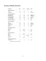
Summary of Editable Parameters . . . . . . . . . . A-1
Battery Replacement . . . . . . . . . . . . . . . . . B-1
Replacing the Battery . . . . . . . . . . . . . . . B-1
Replacement Batteries . . . . . . . . . . . . . . B-1
INDEX . . . . . . . . . . . . . . . . . . . . . . . . I-1
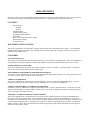
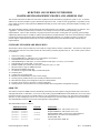
Preface
How To Use This Manual
This manual assumes some knowledge of music theory and terminology, and familiarity with some concepts of electronic
sound generation, the Musical Instrument Digital Interface (MIDI) standard, and other recent advances in music creation and
performing.
Chapter 1 will give you a brief overview of the Kurzweil Model K150X Expander (K150X), and show you how to connect it
to your MIDI controller and start making music right away. SThe manual assumes that your MIDI controller is a piano
keyboard-like controller. However, the K150X will work with any controller which produces standard MIDI signals.
After reading Chapter 1, you should be able to play the K150X’s built-in sounds, and begin to suspect that you can do much
more.
Chapter 2 describes using the K150X in-depth, and gives you an overview of the editors and how to use them. After this
chapter, you should be able to read the chapters on individual editors as you need them.
Chapters 3 through 13 are on individual editors. Within each editor chapter, everything you can do with that editor is
documented, with examples and references to other chapters as needed.
Appendix A is a summary of editable parameters from all the editors.
Appendix B, Battery Replacement, describes how to change the battery in the K150X.
i
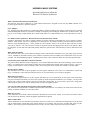
Introduction
Introduction
The Kurzweil Model K150X Expander (K150X) has built-in programs you can play directly, and editors with which you can
modify these programs to create an enormous range of sounds and playing/performance options.
In most synthesizers, the sound begins with a simple electronic waveform that is then filtered and shaped to produce the final
tone. The Kurzweil K150X Expander is also a synthesizer. However, instead of starting off with a simple electronic
waveform, the K150X starts with a computer model of an acoustically rich instrumental sound. These models, which we call
voices, are created by a Contoured Sound Model, which produces the rich, authentic tones for which Kurzweil Music
Systems has become famous.
Programs, Regions, and Layers
In addition to the voices, the K150X offers many sound-modifying resources. By using these resources, we are able to
change a basic voice to create a great variety of new tone colors. The resources are referred to as modifiers. A voice,
together with its associate modifiers, is called a layer.
With the K150X, you can combine layers to form a composite tone color, and then assign that combination of layers to a
region. A region is one group of keys into which the K150X divides the incoming MIDI keyboard information. The K150X
enables you to set up one, two, or three keyboard regions.
A complete keyboard setup is called a program. The program tells where the regions are, which layers are in each region,
and which voice and modifier values are in each layer. The programs are numbered from 0 to 255. A given program may be
selected by the K150X’s front panel, or by a MIDI program change command.
Thus, programs are built up like the branches of a tree. The program is the tree itself, the regions are parts of the tree’s
"trunk", and the layers are "branches" that are attached to the trunk. To continue the analogy, you can think of the K150X as
a "forest" of up to 255 trees. The size of the forest is fixed by the amount of memory in the K150X. You can have up to 255
"trees," but if you build up big trees with a lot of "branches" (that is, a complex program with a lot of layers), it will take
more space in the memory than smaller trees with fewer layers, and you will be able to fit fewer than the maximum of 255 in
your "forest" of programs.
The K150X allows you to build up a program of one, two, or three regions, each of which may have up to seven layers. In
working on your programs, you may set up, change, or remove just a layer, a region of layers, or an entire program.
The Voices
Many voices are built in to every K150X. A list of the resident voices is given in Chapter 8 of this manual. In addition,
every K150X contains voice expansion slots into which supplied voice block integrated circuits are inserted. Additional
expansion slots are also supplied so that you can add more voice block integrated circuits later on.
All voices are instantly available for playing. That is, there is no waiting time to play any of the voices that you have
installed within the instrument.
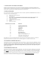
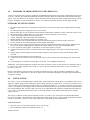
The Modifiers
Modifiers change a voice, or change the manner in which the voice responds to MIDI control signals. Modifiers may be
applied at the layer level, program level, or be instrument-wide. A modifier which is applied at the layer level affects only
that layer, a modifier applied at the program level affects all layers in all regions defined by the program, and an instrumentwide modifier affects all the programs in the K150.
Instrument-wide modifiers include:
•
•
MIDI assignments
Master transposition, tuning, and intonation
1-1
•
Keyboard response adjustments
Program-wide modifiers include:
•
•
•
•
•
Controller ranges
Sizes and balances of regions
Chorusing
Vibrato
Equalization
Layer-wide modifiers include.
•
•
•
•
Voice selection
Voice modification
Layer transposition and tuning
Layer balancing
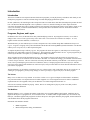
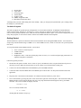
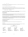
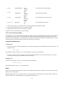
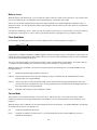
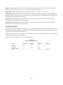
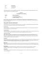
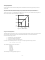
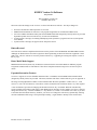
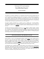
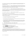
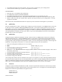
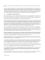
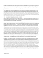
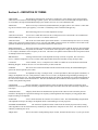
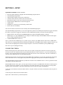
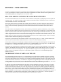
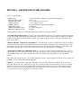
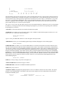
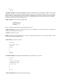
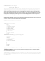
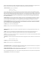
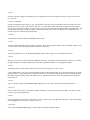
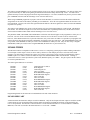
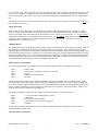
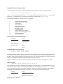
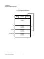
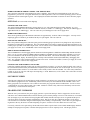
Figure 1-1 shows pictorially how you might look at a single program, its relationship to its regions, layers, editors, and its
relationship to the other programs.
Program 16
Program 15
Chorusing
Region 1
Vibrato
Region 2
Program 17
Equalizer
Region 3
Layer 1
Layer 2
Layer 1
Layer 2
Layer 1
Layer 2
...
...
...
Layer 7
Layer 7
Layer 7
Figure 1-1. Sample Program.
The Editors
The modifiers of the K150X are accessible through its editors. By using the editors to create your own programs from
scratch, or to modify the built-in programs, you can create an enormous range of new and different programs. They, in turn,
may be stored in the K150X, or on an external cassette tape.
The following editors are available:
1.
2.
3.
4.
(MIDI) Channel editor
Tuning editor
MIDI Mode editor
Program editor
1-2
5.
6.
7.
8.
9.
10.
11.
Region editor
Layer editor
Chorusing editor
Vibrato editor
Equalizer editor
(MIDI) Assignment editor
Miscellaneous functions editor
All changes that you make while editing take effect instantly. Thus, you can play the keyboard while you’re editing to hear
the changes as you make them.
The Built-In Programs
The built-in programs are popular playing configurations of conventional instruments, or highlight sound modification
features of the K150X. Program #1, for instance, is a piano. Program #2 combines a piano with a bass: the lowest two
octaves of the keyboard sound like a bass, while the rest of the keyboard remains a piano. You can select and play these and
many other programs, as soon as the K150X is connected to a MIDI controller and an amplifier.
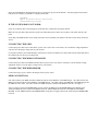
Getting Started
The K150X allows a myriad of connections between itself and other devices through the MIDI interface. We’ll describe a
simple setup with the K150X acting as a MIDI receiver from a MIDI controller, which we’ll assume to be a piano keyboardlike device.
To set up the K150X and one MIDI controller, you will need:
•
•
•
•
110V or 220V AC electrical power
A MIDI controller
A MIDI cable
Headphones with a ¼-inch stereo phone plug (mono or stereo), or a ¼-inch mono phone plug connected to an
amplifier and speaker combination.
Follow this general procedure:
1.
The K150X will operate on either 110V or 220V AC power, and indicates on the rear panel which kind of power it is
currently set up for. Make sure the K150X is set for the voltage in your location before turning it on.
2.
Connect one end of the MIDI cable to the MIDI OUT jack on the MIDI controller.
3.
Connect the other end of the MIDI cable to the MIDI IN jack on the K150X. No other jacks should be used in this
application.
4.
Plug the power cord in between the K150X’s AC LINE IN connector and the AC power source.
5.
Turn on the K150X by pressing the power switch on the lower right side of the front panel. This insures that when your
MIDI controller is powered up the K150X will receive any setup information which might be sent by your MIDI
controller. After a few seconds, the display will read
KURZWEIL 150X
for a few seconds, and then read
C1 P1 PIANO
meaning that the K150X is ready to go.
1-3
6.
Turn on the amplifier, and plug the ¼-inch phone plug into the AUDIO OUT jack on the rear panel of the K150X, and/or
plug the headphones into the headphone jack on the front panel of the K150X.
7.
Adjust the volume control on the front panel of the K150X to a low, but audible level, and press a keyboard key. You
should now be getting an acoustic piano sound.
When using headphones, the volume control should be set to a comfortable listening level. However, when using an external
amplifier or speaker, best results are obtained when the volume level is set as loud as your amplifier will allow without
distorting.
Selecting Between Programs
The display should currently read:
C1 P1 PIANO
meaning that Program number 1, with name "PIANO", is active and assigned to MIDI Channel 1. Press INCR, and the
display should read:
C1 P2 ABS/PNO
You should now be able to play Program number 2, which has an acoustic bass voice in the lower part of the keyboard and a
piano in the upper part of the keyboard. To return to Program number 1, press DECR.
You can use INCR and DECR to step through all the currently existing programs and play them. You can also jump between
non-sequentially numbered programs by entering the number of the desired program using the numbered buttons, and
pressing ENTER. You are now ready learn more about the K150X and what it does.
1-4
Using the K150X
In this chapter you’ll be introduced to the button-pads of the K150X, and briefed on what the individual buttons do and how
they work. This will lead into a discussion of the editors and how to use them.
Communicating with the K150X
All your interaction with the K150X is through the front panel button-pad and display.
Using the buttons on the front panel, you tell the K150X what to do. The K150X gives information back to you visually
through its display, and audibly through its audio output, enabling you to listen to changes as you make them.
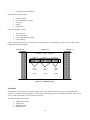
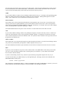
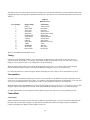
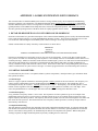
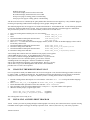
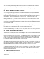
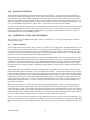
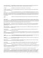
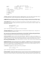
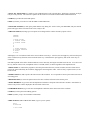
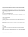
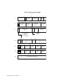
The Buttons on the Front Panel
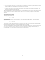
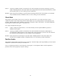
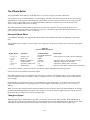
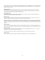
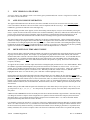
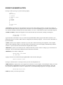
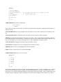
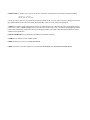
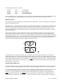
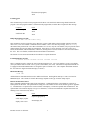
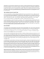
From here on, we’re going to divide the buttons on the front panel into 2 halves: the left button-pad and the right button-pad,
as shown in Figure 2-1. Each of these halves is used to perform different functions.
CHANNEL
TUNE
MIDI
LEFT
CENTER
RIGHT
F1
F2
F3
1
2
3
4
5
6
7
8
9
NO
YES
-
0
PROG
REGION
LAYER
SAVE
CANCEL
UNDO
CHORUS
VIB
EQ
INCR
DECR
CLR
CTRLS
MISC
NEXT
PREV
EDIT
left button-pad
ENTR
right button-pad
Figure 2-1. The Front Panel Buttons.
The Left Buttonpad
The left button-pad is used to select parameters to edit, and to perform various other operations while editing. Although there
are only 12 keys, they perform many operations by doing different things depending on what you’re up to and how you got
there. Sequences of previous button selections can make a difference in what a button does. (Don’t worry, the display helps
you keep track of your button selections.)
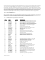
On the Buttons. Written on the buttons are names or abbreviations for what they do if you press them directly (i.e. if you
haven’t just pressed the EDIT button), as shown in Table 2-1.
Table 2-1
Left Button-pad Buttons
Button
F1
F2
F3
SAVE
CANC
UNDO
INCR
Meaning
Function #1
Function *2
Function #3
save
cancel
undo
increment
What It Does
changes - we’ll get back to them
save the current changes
cancel all changes since the last time save was pressed
undoes (re-does) the last value change
increment the value (i.e. raise it)
2-1
DECR
CLR
NEXT
PREV
EDIT
decrement
clear
next
previous
edit
decrement the value (i.e. lower it)
clear the value (usually to 0)
advance to the next parameter (i.e. step forward through the options)
go back to the last parameter (i.e. step backward through the options)
special button, used in sequence with the others above
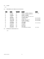
Above the Buttons. Written above the buttons are abbreviations for the K150X’s different editors. The EDIT button gives
you access to the K150X’s editors. You access the editors by pressing the EDIT button first, and then the button below the
abbreviation. (If you’ve ever used a scientific calculator, in which keys have different meanings depending on whether
you’ve pushed the "function" key, this works the same way.) For instance, pressing EDIT F2 selects TUNE, the Master
Tuning Editor. The editors are summarized in Table 2-2.
Table 2-2
Button Sequences for Editors
Word or Abbreviation
Above Button
CHAN
TUNE
MIDI
PROG
REGION
LAYER
CHORUS
VIB
EQ
CONTROLS
MISC
Abbreviation
For
Channel
Tune
MIDI
Program
Region
Layer
Chorus
Vibrato
Equalization
Controls
Miscellaneous
Buttons Sequence
to Press
EDIT F1
EDIT F2
EDIT F3
EDIT SAVE
EDIT QUIT
EDIT UNDO
EDIT INCR
EDIT DECR
EDIT CLR
EDIT NEXT
EXIT PREV
Meaning
Selects the Channel Assignment Editor
Accesses the Master Tune Editor
Selects the MIDI Editor
Accesses the Program Editor
Selects region to edit
Accesses the Layer Editor
Accesses the Chorus Editor
Accesses the Vibrato Editor
Accesses the Graphic Equalization Editor
Accesses the MIDI Control Editor
Accesses the Miscellaneous Editor
The Right Button-pad
There are numbers printed on most of the buttons of the right button-pad. You use these buttons to enter values after you’ve
selected parameters to change with the left button-pad. The new values don’t take effect until you press the ENTR button.
Three of the buttons, ENTR, 0, and -, have special meanings:
ENTR
You’ll be using the ENTR button often. Pressing ENTR means different things at different times:
•
•
enter a selected editor
indicate you’re finished entering a value; Use ENTR after entering a number to let the K150X know you’re
finished. If you’ve used a computer before, think of ENTR as the RETURN button of a computer when used in
this context. If nothing seems to be happening, try pressing the ENTR button. (Don’t worry, you can always
press undo to undo the change.)
0
The 0 button serves 2 different purposes:
• enters 0 for numeric values
• answers "Yes" to K150X questions (the sign button, - is "no".)
- (The sign button)
2-2
Pressing the sign button means different things at different times:
•
•
•
it starts entry of a negative number. When you intend to enter a negative number, press - first.
it steps through 4-way signs. Some K150X values can be positive (+), negative (-), starting positive (±), or
starting negative (-/+). Pressing - steps through these 4 values.
it answers "no" to K150X questions. ("No" is printed above the button.)
Left, Center, and Right
The words "LEFT, "CENTER", and "RIGHT" appear above the 1, 2, and 3 keys. These meanings are significant only in the
Region Editor. They allow you to quickly select which region of the keyboard you want to edit.
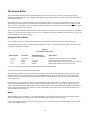
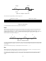
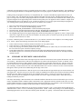
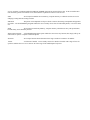
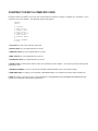
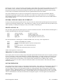
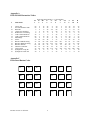
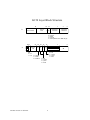
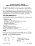
The Display
The K150X communicates back to you visually using the display, which is capable of displaying up to 16 alphabetic and/or
numeric characters. The display gives you the information concisely, using abbreviations and information Fields to show
you what’s happening. The location of a number or abbreviation within the display is important. It can be divided
approximately into 5 fields, as shown in Figure 2-2.
1
2
3
4
5
Figure 2-2. Fields of the K150X Display
When you’re using the Program, Region, or Layer Editors, the number of that program, region, or layer appears in Field 1.
Outside of these editors, Field 2 usually moves over into this field.
The name, or an abbreviation for the name of the parameter being edited appears in Field 2.
When applicable, the sign of the value in Field 4 appears in Field 3. This can be +, −, and sometimes ± or -/+.
The value for the parameter in Field 2 appears in Field 4.
An abbreviation for the units of the value in Field 4, when applicable, appear in Field 5. Table 2-3 shows the abbreviations
the K150X uses in Field 5 and their meanings:
Table 2-3
Units in the K150X Display
Abbreviation
C
ST
dB
ms
Hz
kHz
Unit
cents
semitone
decibels
milliseconds
Hertz
kiloHertz
Meaning
1 cent = 1/100 of a semitone
1/2 of a whole tone (50 cents)
a measurement of loudness
1 millisecond = 1/1000 of a second
cycles per second - frequency
Hertz x 1000
For example, consider the following displays:
2-3
C1.
TUNE
-58C
The Center Region, Layer #1 is being edited. The parameter being edited is TUNE (tuning), whose present value is -58C.
This layer is tuned down -58C (it is 58 cents flat).
P1
250 HZ
+5 dB
Program #1’s equalizer is given +5 dB of emphasis at the 250Hz point.
The display which appears when the K150X is turned on, showing the MIDI channel and program number currently active,
indicates that you are in the Channel Editor, the top-level editor. Any time you want to return to this editor, press EDIT F1.
The display will show the Channel and Program currently active:
C number P number
program-name
This is the K150X’s top-level display. C stands for CHANNEL and P stands for PROGRAM. From here, you can use INCR
and DECR to step through the Programs, or NEXT and PREV to step through the Channels.
Using the Editors
It is through the editors that you display and change parameters in the K150X. Press EDIT to indicate you want to select an
editor. Then select the editor you want by pushing the button below its abbreviation. For example, EDIT F1 selects the
Channel Editor while EDIT UNDO selects the Layer Editor.
Once you are in the editor, the display will identify the program, region, and/or layer that you are editing, the name of or an
abbreviation for the parameter (e.g., .V-DEPTH for vibrato depth) and the current editable value, which will be flashing. To
change a numeric value, simply enter the new value using the numeric button-pad and press ENTR, or use INCR and DECR
to step through the numbers. (Note that flashing stops when you start entering a new value.) The NEXT and PREV buttons
are used to step through the various parameters in that editor.
All changes that you make while editing take effect instantly. Thus, you can play the instrument while you are editing to
hear the changes as you make them.
The Editing Buttons
Once an editor has been selected, the buttons of the left button-pad take on the meanings printed on them.
F1, F2 and F3
These buttons are active only in certain editors, and have special functions which depend on the currently active editor, as
outlined in Table 2-4. These functions are discussed in detail the chapters on individual editors.
Table 2-4
F1, F2 and F3 in Various Editors
Editor
Channel
Program
Region
Layer (selecting)
Layer (using)
Controls
Program List (Misc)
F1
Read Cassette
Rename Program
Delete Region
Delete Layer
Change Layer (up)
Jump to Beginning of List
Jumps 16 Entries
F2
Memory Space
Copy Program
Copy Region
Copy Layer
Change Layer (down)
Jump to Chorus Controls
Insert Program
SAVE and CANC
2-4
F3
Delete Program
Replace Region
Insert Layer
Mute Other Layers
Jump to Vibrato Controls
Delete Program
The SAVE and CANC buttons can be used at any time during editing. SAVE will cause all changes that you have made to
be stored in the K150X’s non-volatile RAM memory. This memory is used to initialize the machine when it is turned on.
CANC will cancel all changes that you have made since the last time SAVE was pressed.
UNDO
If you are in the middle of a numeric entry (no flashing) UNDO cancels the entry (i.e., the display will begin flashing again).
Otherwise, UNDO cancels the last change that you made to the current parameter. Pushing UNDO again will re-do the
change. Thus, UNDO can be used to switch back and forth between two values.
INCR and DECR
These buttons can be used to increment and decrement the current parameter value or entry value. If you use them after
entering a value but before pushing ENTR they just increment and decrement the entered value. If the current parameter
value is displayed (flashing) then INCR and DECR will alter that value directly. For example, if the current value of Master
Tune is 20, pushing INCR is equivalent to pushing 2, 1, ENTR.
The INCR and DECR buttons will repeat at a rate of ten times a second if held down for more than one second.
CLR
If you are in the middle of making a numeric entry (flashing has stopped), CLR just sets the entry value to 0. Otherwise, it
sets the the current parameter value to 0 (the equivalent of pushing 0, ENTR ). For parameters for which 0 is not a legal
value, CLR sets the parameter to the lowest allowable value. For a parameter where a number is not a legal value, CLR sets
the parameter to the default value.
NEXT and PREV
These buttons allow you to step thru the parameters associated with the current editor. If you have started making a numeric
entry, but haven’t pressed ENTR, pressing NEXT or PREV completes the entry for you.
Like INCR and DECR, these buttons repeat if held down for more than one second, but at a slower rate (twice a second).
EDIT
In general, you can use EDIT Fn at any time to select a different editor. Press EDIT EDIT to return to the previous editor
you were in. Since each editor remembers what it was doing when you exited from it, you can bounce back and forth
between editors with little difficulty.
If you have started making a numeric entry, but haven’t pressed ENTR, pressing EDIT completes the entry for you.
To return from all editors, press EDIT and any key on the right button-pad. The display will show the CHANNEL and
PROGRAM number currently active:
C number P number program-name
This is the K150X’s Channel Editor display: C stands for CHANNEL and P stands for PROGRAM. From here, you can use
INCR and DECR to step through the Programs, or NEXT and PREV to step through the Channels.
2-5
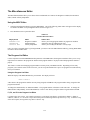
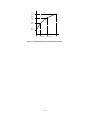
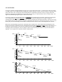
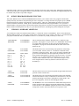
A Block Diagram of the K150X
Figure 2-3 shows the relationships between the various K150X parameters and modifiers, and how they interact to achieve a
certain result. Although reasonably complex, the diagram will become clearer as you become familiar with the K150X and
its operation. It is supplied here only for reference; you don’t need to study it in order to use the K150X.
(large, complex, hardly readable, original diagram not included)
Figure 2-3. The K150X Expander Effects Processing Chart.
2-6
The Channel Editor
The Channel Editor lets you assign programs to individual MIDI channels.
If the instrument is in Omni mode, changing the channel number in the Channel Editor also changes the basic MIDI channel
number. In addition, changing the channel will also change the currently selected program (see program editor below),
unless there is no program assigned to the channel or the currently selected program has been changed.
Using the Channel Editor
Enter the Channel Editor by pressing EDIT F1, and the display will show:
C xx P xxx
program name
Where Cxx is the currently active channel, and Pxxx is the currently active program number.
To change the channel, enter the new channel number with the numeric button-pad and press or use the NEXT and PREV
keys to step through the numbers 1 through 16. If a number greater than 16 is entered using the numeric keypad, the channel
number will be set to the previous channel number when ENTR is pressed.
To de-activate a channel, use CLEAR or 0 ENTR.
Channel Editor Hints
The Channel Editor will not allow you to assign a non-existent program to a channel. In particular, the INCR and DECR
keys will skip over non-existent program numbers.
3-1
The Tuning Editor
The Tuning Editor lets you specify instrument-wide tuning, set a master transposition value, and activate the programmable
intonation table.
Using the Tuning Editor
Select Tuning Editing by pressing EDIT F2. (The abbreviation TUNE is printed above the F2 key on the button-pad.)
The parameters shown in Table 4-1 can be edited. One will appear in the display; the others can be selected by using NEXT
and PREV.
Table 4-1
Tuning Editor Parameter
Display Reads
Parameter
MAST TUNE
TRANSPOSE
INTONATION
REFERENCE KEY
Master Tuning
Transposition
Intonation Switch
Reference key
Adjustable Values *
(use INCR and DECR)
±0-125C
±60ST
On/Off
Entire Musical Scale
What it Does
Tunes the entire instrument.
Transposes the entire instrument.
Switch for intonation parameters.
Sets a reference key for intonation.
* If the value is numeric, you can also enter the value directly with the right button-pad and press ENTR.
Note that you can specify tuning and transposition values for individual layers with the Layer Editor (see Layer Editing).
See the sections on each parameter later in this chapter.
Master Tuning
When the display reads MAST TUNE, the pitch of the K150X may be tuned by ±125C.
Enter a value using the numeric button-pad and press ENTR, or use INCR and DECR to change the value by 10 cent
increments.
If a value greater than 125 is entered using the numeric button-pad, the value will be set to 125 when ENTR is pressed.
This tuning is in addition to any tuning specified for a particular layer with the .TUNE parameter in the Layer Editor. For
example, if the Master Tuning for the K150X is set at +3C, and a layer is given a tuning of +2C, the layer will have a +5C
tuning relative to the natural pitch.
Transposition
When the display reads TRANSPOSE, the K150X can be transposed from 0 to ±6O semitones.
Enter a value using the numeric button-pad and press ENTR, or use INCR and DECR to change the value by 1 semitone
increments.
If a value greater than 60 is entered using the numeric button-pad, the value will be set to 60 when ENTR is pressed.
This transposition is in addition to any transposition specified for a particular layer with the .TRANS parameter in the Layer
Editor. For example, if the master transposition for the K150X is set at +3ST, and a layer is given a transposition of +2ST,
the layer will have a +5ST transposition relative to the natural tone.
Intonation
4-1
Used in conjunction with the Intonation Table Editor, which allows you to adjust the micro-tonal distance between individual
intervals, this parameter determines whether the values specified with that editor will be active or not.
When the display reads INTONATION, you can change the value of the switch. Use INCR and DECR to change the value
between off and on. The default is off.
Reference Key
Used in conjunction with the Intonation Table Editor, which allows you to adjust the micro-tonal distance between individual
intervals, this parameter allows you to specify which key you will be playing in so that the intervals will be properly adjusted
for that key. The default key is C.
When the display reads REFERENCE KEY, you can change the key. Use INCR and DECR to step through the musical
scale.
4-2
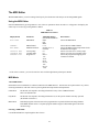
The MIDI Editor
With the MIDI Editor, you select settings which specify how the K150X will interpret its incoming MIDI signals.
Using the MIDI Editor
Enter the MIDI Editor by pressing EDIT F3. One of the two parameters shown in Table 5-1 will appear in the display; the
others may be accessed by pressing NEXT or PREV.
Table 5-1
MIDI Editor Parameters
Display Reads
Parameter
MIDI MODE
MIDI Mode
CHANNEL
MOD WHEEL
MIDI Channel
Modulation Wheel
VELOCITY MAP
LOUDNESS MAP
PROGRAM LIST
Velocity Map
Loudness Map
Program List
Adjustable Range *
(use INCR and DECR)
Omni
Poly
Multi
I - 16
Normal (0- 12 7)
Centered
0-7
0-7
Direct
1-32
33-64
65-96
97-128
1-64
65-128
1-128
What it Does
Selects the MIDI Mode
Selects the basic MIDI Channel
Selects the MIDI signal interpretation for the
modulation wheel signal
Selects one of the seven velocity maps
Selects one of the seven loudness maps
Selects the program list mapping from
controller to K150X.
* If the value is numeric, you can also enter the value with the right button-pad and press ENTR
MIDI Mode
About MIDI Modes
Information can be transmitted on 16 distinct channels in the MIDI interface. The K150X can respond in three ways to this
incoming information, with each of the ways having different interpretations and implications.
Omni Mode
The K150X will respond to incoming information on any of the 16 MIDI Channels.
This is the default mode.
Poly Mode
The K150X will respond to incoming information only on the specific channel currently specified
(the default is Channel 1).
Multi Mode
Individual programs of the K150X can be programmed to respond to different incoming channels.
Each MIDI channel can have a separate program number assigned. Multi Mode ignores the Omni
on/off message.
Selecting a MIDI Mode
Use INCR and DECR to step through the three choices.
5-1
MIDI Channel
The MIDI Channel parameter lets you select the basic MIDI channel. The default channel is Channel #1.
When the display shows CHANNEL you can select the Channel number. Enter the new channel number with the numeric
button-pad and press ENTR, or use the INCR and DECR keys to step through the numbers 1 through 16. If a number greater
than 16 is entered using the numeric keypad, the channel number will be set to the previous channel number when ENTR is
pressed.
Mod Wheel
Your controller’s modulation wheel may or may not be centered. You can select which way the K150X interprets the MIDI
signal coming from your modulation wheel.
When the display reads MOD WHEEL, you can use the INCR and DECR keys to select between "Normal" and "Centered."
In Normal mode, signals coming from the modulation wheel are given the values 0-127. In Centered mode, the values are
shifted down to be from -64 to +63, with 0 as the center point.
Velocity Map
The K150X contains 8 velocity maps, which determine how the key velocity signals coming from your MIDI controller will
be interpreted. These velocity maps allow you to get different response characteristics from your MIDI controller.
When the display reads VELOCITY MAP, select one of the velocity maps by pressing INCR or DECR, or enter a value from
0-7 directly with the numeric keypad, and press ENTR. The default velocity map is map #0, which is a linear mapping in
which increased MIDI values result in proportionally increased interpretations by your K150X. Although 7 different default
velocity maps are supplied, the maps themselves can be modified with the Velocity Map editor under the Miscellaneous
Editor. See the Miscellaneous Editor for more information.
5-2
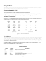
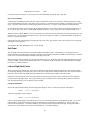
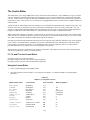
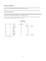
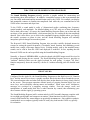
Loudness Map
The K150X contains 8 loudness maps, which determine how the key velocity signals coming from your MIDI controller will
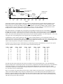
be interpreted. These loudness maps allow you to get different volume characteristics from your MIDI controller.
When the display reads LOUDNESS MAP, select one of the velocity maps by pressing INCR or DECR, or enter a value
from 0-7 directly with the numeric keypad, and press ENTR. The default loudness map is map #0, which is a linear mapping
in which increased MIDI values result in proportionally increased volume.
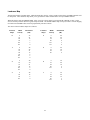
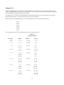
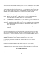
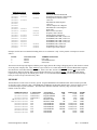
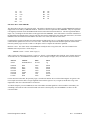
The values of the 8 loudness maps are as follows:
Loudness
Map #
MIDI
Velocity
Attenuation
(dB)
Loudness
Map #
MIDI
Velocity
Attenuation
(dB)
0
0
32
48
84
110
127
26
21
17
7
3
0
4
0
28
74
96
116
127
64
54
12
8
3
0
1
0
26
32
48
84
115
127
48
26
21
17
6
3
0
5
0
32
64
96
24
18
12
6
2
0
10
32
48
112
127
48
30
21
17
6
0
6
0
32
64
96
127
30
20
10
5
0
3
0
64
96
127
48
12
5
0
7
0
32
64
96
127
36
24
12
3
0
5-3
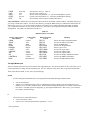
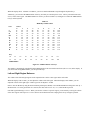
Program List
From your MIDI controller, you will be able to directly select only a limited subset of the 255 program numbers of the
K150X. The PROGRAM LIST parameter in the MIDI editor lets you select how your controller’s program setup numbers
will be mapped into the program numbers of the K150X.
This feature works in conjunction with the Program List Miscellaneous Editor, where you map the list entry numbers to
K150X program numbers. See the Miscellaneous Editor for more information.
When the display reads PROGRAM LIST, use INCR and DECR to select among the following choices:
Direct
1- 32
33- 64
65- 96
97-128
1- 64
65-128
1-128
The way that these choices are interpreted by the K150X is outlined in Table 5-2.
Table 5-2
Program List Modes
List Mode
MIDI #
Maps to ...
K150X #
Direct
0 - 127
program
1 - 128
1 - 128
0 - 127
list entry
1 - 128
1 - 64
0 - 63
64 - 127
list entry
1 - 64
1 - 64
65 - 128
0 - 63
64 - 127
list entry
65 - 128
65 - 128
1 - 32
0 - 31
32 - 63
64 - 95
96 - 127
list entry
1 - 32
1 - 32
1 - 32
1 - 32
33 - 64
0 - 31
32 - 63
64 - 95
96 - 127
list entry
33 - 64
33 - 64
33 - 64
33 - 64
65 - 96
0 - 31
32 - 63
64 - 95
96 - 127
list entry
65 - 96
65 - 96
65 - 96
65 - 96
97 - 128
0 - 31
32 - 63
64 - 95
96 - 127
list entry
97 - 128
97 - 128
97 - 128
97 - 128
5-4
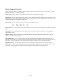
The Program Editor
Programs are the K150X’s top-level construct, under which everything else associated with a particular keyboard
configuration and sound quality is defined. Each program can divide the keyboard into three regions and each region can
have up to seven sound layers. Each sound layer specifies a voice as well as a number of modifiers which alter the
characteristics of the voice. You can define up to 255 programs, but the actual number can be less, depending on how
complicated each program is.
Programs may be assigned to individual MIDI channels. In addition, each program contains a set of parameters which
control the programmable chorusing effect and a set of parameters which control the programmable vibrato oscillator. These
effects are discussed in separate sections.
Using the Program Editor
Selecting and Editing Programs
1.
Select Program Editing by pressing EDIT SAVE. When you enter the program editor, the display will show
something similar to:
PROG 1
PIANO
• the currently selected program’s number (1 in our example),
• the currently selected program’s name (PIANO - an acoustic piano),
2.
Select a program to work on by using INCR, DECR, NEXT, PREV, or select it by number using the numeric button-pad
and press ENTR. Depending on what program numbers you select, and what their statuses are, you might see these
variations in the display as you change programs:
• An asterisk, *, as in:
PROG 1 *PIANO
This means that edits have been made to a built-in program, or that a program is user created. In this case, for
instance, the PIANO program has been modified. You can delete the modifications by pressing F1. The * will
disappear, and the built-in program will be restored.
Note that built-in programs cannot be deleted - only modifications made to them can be deleted.
If you wanted to save the modified built-in program, you could copy it to an undefined program before deleting the
changes. See Creating Programs later in this chapter.
• A question mark, ?, as in:
PROG 206 ?UNTITLED
A question mark designates an undefined program number. In this case, Program #206 is empty.
UNTITLED is the default name for any program which has not been named, and is not an indicator of an undefined
program. For example,
PROG 206 *UNTITLED
is not empty, because there is no question mark.
To change the name of program from UNTITLED, see Renaming Programs, below.
3.
Press ENTR to start choosing among the parameters. One of the parameters shown in Table 6-1 will appear in the
display. Use NEXT and PREV to step through the parameters.
6-1
Table 6-1
Program Editor Parameters
Display Reads
Parameter
.P-BEND
.K-BEND
.SFT-PDL
.L-SPLIT
.R-SPLIT
.L-BAL
.R-BAL
pitch wheel bend
key pressure bend
soft pedal
left split point
right split point
left region balance
right region balance
Adjustable Range *
(use INCR and DECR)
±60ST
±60ST
±30dB
C0-C9
C0-C9
±15dB
±15dB
What it Does
Sets the range and direction of the pitch bender.
Sets the range and direction of key pressure pitch bending.
Sets the range of the soft pedal.
Delineates the lower bound of the center region.
Delineates the upper bound of the center region.
Adjusts the volume of the left region.
Adjusts the volume of the right region.
* If the value is numeric, you can also enter the value with the right button-pad and press ENTR.
See the sections on each parameter later in this chapter.
F1, F2, and F3 in the Program Editor
In the Program Editor, F1 initiates program renaming. F2 initiates program copying. and F3 deletes the current program, as
described below.
Renaming Programs
Undefined and user-created programs have the default name UNTITLED. To change the name:
1.
Press F1. The display will ask
RENAME PROGRAM?
Press 0 (yes) to continue the re-naming process, or press - to quit. If you press 0 (yes), the first letter of the current
name will start blinking. For instance, if the current name is UNTITLED, the U will start to blink.
2.
Press the INCR or DECR button. The letter will change to another character. For instance, the U in UNTITLED will
change to V or T, depending on whether you pressed INCR or DECR. Using these two buttons, you can select any of the
letters of the alphabet, the numbers 0 through 9, or the characters "/", "_", or "*". Choose the first character of the new
name in this way.
3.
To move to the next character position, press NEXT. Use INCR or DECR to repeat the process described in (2) above.
To return to a previous character position, press PREV.
4.
To exit, press F1.
Copying Programs
To copy the current program, press F2. The display will ask
COPY PROGRAM?
Press 0 (yes) to copy the program. The display will read:
COPY current-program number TO current-program number
Enter the program number you want the current program copied to, and press ENTR. Assuming the program number you
selected was empty, the program will be copied, and you will now be editing the program of the new program number.
If a program already existed under the number you selected, the display will read.
6-2
REPLACE PROGRAM?
Press 0 (yes), and the program will be replaced. Press − (no), and you will return to the
COPY current-program number TO current-program number
display, where you can enter a different program number.
Deleting Programs
To delete an existing program, push F3. You will be asked to confirm that you do indeed wish to delete the program:
DELETE PROGRAM?
With the question mark flashing. Push 0 for "yes" or − for "no". If you respond yes, the program will be deleted. Remember
that built-in programs cannot be deleted.
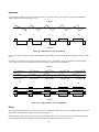
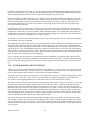
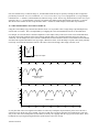
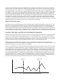
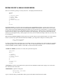
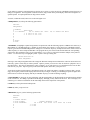
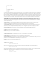
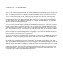
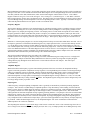
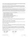
Pitch Wheel and Key-Pressure Bend
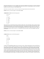
Note bending is when the played note rises or falls to another note by a smooth transition, as in Figure 6-1. It may or may not
return to the original note.
Figure 6-1. Note Bending.
The K150X allows you to control this effect in two ways - through the pitch wheel or through key pressure. Here, in the
program editor, you select the ranges in semitones for both of the bending options. The .P-BEND switch in the Layer Editor
allows you to select whether either or both of these options is active for a particular layer. All layers in the program set to the
same option will have the same amount of bend. With the .P-BEND switch, you can select among four pitch bending
options: off, wheel, press, or both. (See Layer Editing for more information.)
Pitch Wheel Bending
Assuming your MIDI controller has an assignable pitch wheel, it can bend a played note up or down, depending on which
way the wheel is rotated (no bending occurs when the wheel is in the center of its rotation). In order to hear the effect of your
changes, the .P-BEND parameter in one or more of the layers being played has to have the value wheel or both, and there has
to be proper MIDI assignment of the pitch wheel signal and/or the key velocity signal from the MIDI controller to the
K150X.
When the display reads .P-BEND you can adjust how many semitones away from the played note wheel rotation can bend
the sound. Use INCR and DECR to change the value by 1 semitone increments, or enter a value using the numeric buttonpad and press ENTR.
The value given is the amount in each direction. For instance, if 3ST is the value, the pitch wheel will bend the played note 3
semitones up and 3 semitones down. The maximum range is +/-6O semitones. New programs have their P-BEND set at a
default value of 2ST.
The sign of the value shows the relationship between the direction the pitch wheel is rotated and the direction of the pitch.
The convention is usually.
Wheel Direction
clockwise or up
Note Direction
up
6-3
Sign of Semitone Value
+
counterclockwise or down
down
-
If your pitch wheel is different, or you want to reverse the relationship, change the sign of the value.
Key-Pressure Bending
Assuming that your MIDI keyboard sends after-pressure information, notes can be specified to bend when played, the range
of the bend depending on the force with which you press the keys. The direction of the bending is specified by the sign of the
range. A positive value means the sound bends up from the played note. A negative value means the sound bends down.
In order to hear the effects of your changes, the .P-BEND parameter in one or more of the layers being played must be set to
Press or Both. There must also be proper MIDI assignment of the key velocity signal from your keyboard to the K150X.
When the display reads .K-BEND, you can set the distance (in semitones) after the played note at which pressing the key will
bend the note. Use the numeric button-pad to enter a value directly and press ENTR, or use INCR and DECR to change the
value by 1 semitone increments.
Change the direction of the bending by changing the sign of the value. The semitone value will be positive for a rising bend
and negative for a failing one.
New programs have their KP-BEND set at +1 ST by default.
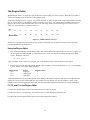
Soft Pedal
The soft pedal acts as an attenuator to control the loudness and timbre of notes. This parameter is an unsigned value (in
decibels) which sets the range of the soft pedal. Note that if the soft pedal is assigned to a MIDI switch controller, it will take
on the values 0 (when OFF) and the maximum pedal range (when ON).
When the display reads .SFT-PDL, you can adjust the timbre range over which the sound will be diminished when the pedal
is pressed ±30dB. Use the numeric button-pad to enter a value directly and press ENTR or use INCR and DECR to change
the value by 1 decibel increments.
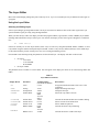
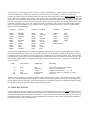
Left and Right Split Points
When a program is first defined, the center region is defined as being the full width of the keyboard. Left and right regions
are created by defining left and right split points for the center region, which essentially shorten the center region on either or
both sides. That is, the left and right split points delineate the lower and upper bounds of the center region.
Keyboard events which occur below the left split point are routed to the left region; events which are above the right split
point are routed to the right region. Each region can be given its own distinct layers, allowing the keyboard to be divided
into up to three different voices of arbitrary keyboard width.
Setting the Split Points
Select each split point individually when the appropriate display is visible. For the left split point, the display is
number .L-SPLIT current note
and for the right split point, the display is
number .R-SPLIT current note
number is the program number being edited, and current note is the keyboard position of the appropriate split. current note
will be flashing. In a program without a current left-hand split, the left-hand split is defined to be C in the 0 octave (the
bottom most keyboard key). C0 would be flashing. In a program without a current right-hand split, the right-hand split is
defined to be C in the 9th octave (the top most keyboard key). C9 would be flashing.
6-4
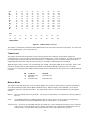
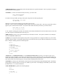
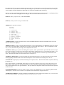
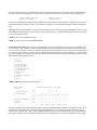
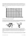
When the display shows .L-SPLIT or .R-SPLIT, you can use INCR and DECR to step through the keyboard keys.
Alternately, you can select the MIDI number of the key at which you want the split to occur. The key selected becomes the
last key in the center region. The MIDI number for each key is shown in Table 6-2, and Figure 6-2 relates the MIDI numbers
to keys on the keyboard.
Table 6-2
MIDI Key Number Chart
Note
C
C#
D
D#
E
F
F#
G
G#
A
A#
B
Key
C0
Octave
0
12
13
14
15
16
17
18
19
20
21
22
23
C1
1
24
25
26
27
28
29
30
31
32
33
34
35
2
36
37
38
39
40
41
42
43
44
45
46
47
3
48
49
50
51
52
53
54
55
56
57
58
59
4
60
61
62
63
64
65
66
67
68
69
70
71
5
72
73
74
75
76
77
78
79
80
81
82
83
6
84
85
86
87
88
89
90
91
92
93
94
95
7
96
97
98
99
100
101
102
103
104
105
106
107
8
108
109
110
III
112
113
114
115
116
117
118
119
C2
C3
C4
C5
C6
C7
C8
C9
12
24
36
MIDI Number
48
60
72
84
96
108
120
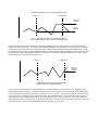
Figure 6-2. MIDI Numbers of C Keys.
The number is automatically translated from the MIDI number to the associated musical note (the new note) in the display. If
you selected the wrong MIDI number, you can repeat this step.
Left and Right Region Balances
The volume of the left and right regions can be adjusted relative to the center region and to each other.
When the display reads .L-BAL, you can adjust the volume of the left region. When the display reads .R-BAL, you can
adjust the volume of the right region. Either region can be adjusted : ±15dB.
Enter a value in dB directly using the numeric button-pad and press ENTR, or use INCR and DECR to change the value by 1
dB increments. If a value greater than 15 is entered, the value will be set to 15 (+ or -) when ENTR is pressed.
Note that region balancing is relative. When you raise the volume of a specific region, you are actually reducing the volume
of the other regions with respect to it. This is done to insure that the K150X’s output gain is always as high as possible.
6-5
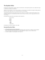
The Region Editor
With the Region Editor, you select the region of the active program which you want to work in. When the Layer Editor is
selected, the editable layers will be those of the selected region.
Technically, all programs have 3 regions. It is possible, however, to define the split points (in the Program Editor) such that
they are outside the range of the MIDI keyboard or controller you are using. For example, there are MIDI values for notes
from C in the 0 octave, to B in the 9th octave, but even a "full" range, 88-key piano keyboard goes only from A in the 0
octave to C in the 8th octave, as shown in Figure 7- 1.
Key
C0
C1
C2
C3
C4
C5
C6
C7
C8
B9
12
24
36
MIDI Number
48
60
72
84
96
108
119
Figure 7-1. MIDI Numbers of C Keys.
Therefore, it is possible to select a region and edit its layers even though you can’t play it because no part of the actual
playing keyboard has been assigned to it.
Using the Region Editor
1.
Enter the Region Editor by pressing EDIT CANC. The regions edited will be those of the currently active program. To
edit the regions of another program, you must first select it to be the currently active program, and then press EDIT
CANC. The display will show:
Pn .CNTR LYRS r
where n is number of the current active program, and r is the number of layers currently defined for the region.
2.
Select a region to work on by using INCR, DECR, NEXT, or PREV, or select it using buttons 1, 2, or 3, corresponding
to "left", "center", and "right", and press ENTR.
Display Reads
.LEFT
.CNTR
.RGHT
Region
left region
center region
right region
Region Number
1
2
3
Additional information is given on the right side of the display on the number of layers in that region. The right side of the
display can read "0 LYRS", meaning that there are currently no layers defined, or it can read "LYRS n", where n is the
number of layers currently defined for that region. See the Layer Editor chapter for information on creating sound layers.
F1, F2, and F3 in the Region Editor
F1 deletes the selected region. You will be prompted before the region is deleted.
F2 copies the region in a storage buffer. You can then use F3 to insert that region somewhere else.
F3 replaces the selected region with the region stored in the storage buffer with F2 .
7-1
The Layer Editor
Most of the sound-shaping editing takes place at the layer level. Up to seven sound layers may be defined for each region of
a program.
Using the Layer Editor
Selecting and Editing Layers
Select Layer Editing by pressing EDIT UNDO. The layers selected to be edited are those of the center region unless you
specified another region previously using the Region Editor.
When you enter the layer editor, the display will show the program number, region (LEFT, CNTR, or RGHT), layer number
(flashing) and total number of layers in the region. For instance, the display for the center region of Program #1 would look
like:
P1
.CNTR LYR 1/1
If there are currently two or more layers defined, select a layer to work on by using INCR, DECR, NEXT, or PREV, or select
it by number using the numeric button-pad and press ENTR. If there is only one layer defined, that layer is the default layer
to edit, unless INCR is pressed, creating a new layer (see Creating and Deleting Layers).
Press ENTR to start choosing among the parameters for the selected layer. The display will show on the left side:
•
•
the region
− L for LEFT
− C for CENTER
− R for RIGHT
the Layer number
The parameters shown in Table 8-1 can be edited. One will appear in the display; the others can be selected using NEXT and
PREV.
Table 8-1
Layer Editor Parameters
Display Reads
Parameter
.VN
Voice
.TUNE
.TRANSPOSE
.T-MODE
Tuning
Transposition
Timbre-Mode
.T-SHIFT $
.T-SELECT &
.T-LEVEL
.B-MODE
Timbre-Shift
Timbre-Select
Timbre Level
Balance Mode
.BALANCE
Balance Level
Available Values
(use INCR and DECR)
a voice
±125C
±60ST
Fixed
Slider
A-Veloc
Select
±60ST
C0-C9
±30dB
Fixed
Slider
A-Veloc
±15dB
What it Does
Assigns the number and name of the voice to the
sound layer
Adjusts the tuning of the layer
Transposes the layer
Selects the way timbre is chosen
Controls the amount and direction of timbre shifting
Selects one note for all timbre shift
Selects Timbre Proportions
Controls the mode of layer balancing
Controls the relative volume of the layer
8-1
.P-MODE
Pitch Bend Mode
.C-MODE
Chorus Mode
.V-MODE
Vibrato Mode
.EQUALIZER
EQ Switch
Controls the mode of pitch bending
Off
P-Wheel
K-Press
Both
Off
M-Wheel
K-Press
Fixed
Off
M-Wheel
K-Press
Fixed
Off
On
Turns chorusing on and off
Controls the action of the vibrato unit
Turns equalization on and off
* If the value is numeric, you can enter the value with the right button-pad and press ENTR.
$ Does not appear when Select value is selected for T-SHIFT.
& Appears only when Select value is selected for T-SHIFT.
See the sections on each parameter later in this chapter.
F1, F2, and F3 in the Layer Editor
The operation of F1, F2, and F3 changes depending on whether you have pressed ENTR to begin editing the layer parameters
for a specific layer (step 3 above). Once you confirm the selection and begin editing the parameters (step 3 above), these
buttons have different meanings. F1 and F2 allow you to change the layer selection without re-entering the editor. F3 mutes
the other layers in the region, allowing you to hear only the layer you are editing.
Creating and Deleting Layers
Creating Layers
1.
To create a new layer, select the uppermost layer currently defined using any of the methods above and press INCR. The
display will read
New Layer?
Press ENTR, to define a new layer, or - to cancel the request. The new layer will be blank.
2.
To create a new layer from an existing one, select an existing layer and press F2 to copy it, then press F3 to insert the
copied layer into the region. Note that F3 always inserts layers.
Deleting Layers
To delete an existing layer, press F1. You will be asked for confirmation:
Delete Layer?
Press ENTR to delete a layer, or - to cancel the request.
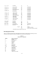
Voice
The voice is the built-in sound selected as a basis for all editing changes in this layer. When a new layer is first defined, the
default voice is acoustic piano.
When the display reads .VN, you can select the voice. Enter the number of the desired voice using the numeric button-pad
and press ENTR, or use INCR and DECR to step through the available voices.
8-2
The built-in voices are either accurate electronic reproductions of conventional instruments, or unconventional sounds which
highlight the unique sound generation capabilities of the K150X. The built-in voices include these Resident Voices listed in
Table 8-2.
Table 8-2
Resident Voices
Voice Number
1
2
3
4
5
6
7
8
9
10
11
12
13
14
Display Reads
PIANO
ROCK PNO
SOFT PNO
ELECPNO
BR E-PNO
HARPISCHD
SOFTHPCD
A BASS
E BASS
SOFT EBS
VIBES
MARIMBA
JAZZ ORG
ROCK-ORG
Sound Name
Acoustic Piano
Rock Piano
Soft Piano
Electric Piano
Bright Electric Piano
Harpsichord
Soft Harpsichord
Acoustic Bass
Electric Bass
Muted Electric Bass
Vibes
Marimba
Jazz Organ
Rock Organ
There are also additional Sound Block Voices.
Tuning
Each layer can be individually tuned by cents. This tuning is in addition to the master tuning for the entire device as
specified with the Tuning Editor. For example, if the Master Tuning for the K150X is set at +3C, and a layer is given a
tuning of +2C, the layer will have a +5C tuning relative to the natural pitch.
When the display reads .TUNE you can adjust the tuning of the layer from 0 to +/-125 Cents. Enter a value using the
numeric button-pad and press ENTR, or use INCR and DECR to change the value by 10 cent increments.
If a value greater than 125 is entered using the numeric button-pad, the value will be set to 125 when ENTR is pressed.
Transposition
Each layer can be individually transposed by semitones. This transposition is in addition to the master transposition for the
entire device as specified with the Tuning Editor. For example, if the master transposition for the K150X is set at +3ST, and
a layer is given a transposition of +2ST, the layer will have a +5ST transposition relative to the natural tone.
When the display reads .TRANSPOSE you can adjust the transposition of the layer from 0 to +/-60 semitones. Enter a value
using the numeric button-pad and press ENTR, or use INCR and DECR to change the value by 1 semitone increments.
If a value greater than 60 is entered using the numeric button-pad, the value will be set to 60 when ENTR is pressed.
Timbre Mode
About Timbre
Timbre describes the harmonic content of the note in addition to the nominal pitch. For most conventional instruments, the
harmonic content of the timbre changes over time while the nominal pitch remains reasonably constant. The harmonic
content of the timbre also changes with the loudness of the note.
8-3
All built-in sounds have a pre-selected timbre formula as a component of every note. Timbre-Shift allows you to override the
default timbre and choose another timbre for a keyboard key when it is pressed. With Timbre-Shift, you can override the
internal formula and use the timbres from other notes in the scale in conjunction with the nominal pitch. Timbre shifts are
similar to transpositions, but they only change the harmonic content of the note and have no effect on the pitch of the note.
The effect of timbre-shifting varies depending on the built-in voice. In the case of the acoustic piano voice, positive timbre
shifts, which will cause the timbres from lower notes to played at higher pitches, result in a bright, funky sound. Negative
adjustments, which use the timbres from higher notes to be played at lower pitches, result in a darker sound.
The Timbre Mode Options
When the display reads .T-MODE, you can choose among four options for selecting your timbres. The default option is
manual. Use INCR and DECR to step through the choices.
Manual
When used with the default value for .T-SHIFT (0 semitones), this option creates the default timbre mode.
Picking a shift in semitones with .T-SHIFT changes the sound (See Timbre-Shift Value).
Slider
If your MIDI controller has a MIDI-assignable slider or wheel, you can set it up so that you can interactively shift
the timbre between the nominal timbre and .T-SHIFT selected timbre by moving the controller. In order for this
option to work, you have to make the proper MIDI assignment of the controller (see Assignment Editor).
Attack Velocity (A-VELOC) If your MIDI controller can transmit key velocity information, the amount of .T-SHIFT timbre
applied to the nominal pitch can be proportional to the velocity with which the key is played by selecting the .AVELOC Timbre-Shift option.
Select
Used in conjunction with the .T-SELECT, this option takes the timbre from one note and applies it to all notes.
You choose the note with the .T-SELECT parameter (see Timbre-Select). The default note is middle C (C4 = C in
the 4th octave).
Timbre-Shift Value
Used in conjunction with the first three Timbre-Shift Modes described above (manual, slider, or a-veloc), this parameter
appears as a Layer Editor Parameter only if one of those first three modes is selected, and not if the select option is chosen. It
allows you to specify the amount to shift the timbre, relative to the played note, in semitones. For instance, if the TimbreShift Value is given as +1ST, and C is played, then the timbre for C# will be played with the nominal B pitch. Likewise, if
the Timbre-Shift Value is given as -1 ST, and C is played, then the timbre for C# will be played.
When the display reads .T-SHIFT you can adjust the timbre shift of the layer from 0 to ±60 semitones. 0 is the default, and
applies all timbre-shifts to their nominal pitches. Enter a value using the numeric button-pad and press ENTR, or use INCR
and DECR to change the value by 1 semitone increments. To change the sign of the value, use the - key.
In general, positive timbre-shifts result in a brighter sound, while negative timbre-shifts result in a duller sound.
Timbre-Select
Used in conjunction only with the Select option of the Timbre-Shift Mode parameter, this parameter allows you to specify the
note whose timbre will be applied to all the notes. The default note is middle C (C4 = C in the 4th octave).
There are 2 ways to select the note. Press INCR and DECR to step through the musical scale. Alternatively, you can select
the MIDI number of the key whose timbre shift you want. Input the value using the numeric button-pad and press ENTR.
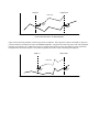
The MIDI number for each key is shown in Table 8-3, and Figure 8-1 relates the MIDI numbers to keys on the keyboard.
Table 8-3. MIDI Key Number Chart.
Note
C
Octave
0
1
12
24
2
36
3
48
4
60
5
72
6
84
8-4
7
96
8
108
C#
D
D#
E
F
F#
G
G#
A
A#
B
Key
C0
13
14
15
16
17
18
19
20
21
22
23
C1
25
26
27
28
29
30
31
32
33
34
35
37
38
39
40
41
42
43
44
45
46
47
49
50
51
52
53
54
55
56
57
58
59
61
62
63
64
65
66
67
68
69
70
71
73
74
75
76
77
78
79
80
81
82
83
85
86
87
88
89
90
91
92
93
94
95
97
98
99
100
101
102
103
104
105
106
107
109
110
III
112
113
114
115
116
117
118
119
C2
C3
C4
C5
C6
C7
C8
C9
12
24
36
MIDI Number
48
60
72
84
96
108
120
Figure 8-1. MIDI Numbers of C Keys.
The number is automatically translated from the MIDI number to the associated musical note in the display. If you selected
the wrong MIDI number, you can repeat this step.
Timbre-Level
The loudness proportions between timbres for the note being played can be modified. This parameter changes the
relationship of key velocity to timbre without affecting the relationship of key velocity to loudness. Its effect can be thought
of as being similar to the soft pedal, but with reversed values: a +30dB value given to .T-LEVEL will have the effect of
emphasizing the loud timbres, while the same value given to .SFT-PDL would emphasize the soft timbres.
When the display reads .T-LEVEL, you can adjust this value ±30dB. The default is 0dB, which is full range. Enter a value
in decibels using the numeric button-pad and press ENTR, or use INCR and DECR to change the value in 1 decibel
increments. If a value greater than 30dB is entered using the numeric button-pad, the value will be set to 30dB when ENTR
is pressed.
dB
+30
0
-30
T-LEVEL
loud timbre only
full range
soft timbre only
SFT-PDL
soft timbre only
loud timbre only
Balance Mode
The volume of each individual layer can be set with the Balance Level parameter described next, and can be controlled by
one of three methods selectable with the Balance Mode Parameter. When the display reads .B-MODE, you can choose
among three options for controlling the balance. The default mode is manual. Use INCR and DECR to step through the
choices:
Manual
This is the default mode for layer balance. The value given in the Balance Level parameter is directly applied to
the layer.
Slider
If your MIDI controller has a MIDI-assignable slider or wheel, you can set it up so that you can interactively
control the balance level between 0dB and the value set with the Balance Level parameter.
Attack Velocity (A-VELOC) If your MIDI controller can transmit key velocity information, the balance can be controlled
by key velocity. When the display reads .A-VELOC, the balance level is scaled between 0dB and the value set
with the Balance Level parameter, and proportional to the velocity with which the key is pressed.
8-5
Balance Level
When the display reads .BALANCE, you can control the volume of this layer relative to the other layers. The volume of this
layer can be adjusted to be 0 to 12dB softer than an unadjusted layer. The default value is 0dB.
Enter a value in decibels using the numeric button-pad and press ENTR, or use INCR and DECR to change the value in 1
decibel increments. If a value greater than 12dB is entered using the numeric button-pad, the value will be set to 12dB when
ENTR is pressed.
Note that layer balancing is relative. When you raise the volume of a specific layer, you are actually reducing the volume of
the other layers with respect to it. This is done to insure that the K150X’s output gain is always as high as possible.
Pitch Bend Mode
Pitch bending is when the played note rises or falls to another note by a smooth transition, as in Figure 8-2.
Figure 8-2. Pitch Bending.
Assuming that your MIDI controller has a MIDI-assignable continuous controller such as a wheel, knob, or slider, and/or can
transmit key after-touch information, this parameter allows you to choose which combination (if any) of control information
will control the pitch bending for this layer.
The range of the pitch bending is a program-wide parameter and is controlled in the Program Editor. The default values are
+2 semitones for wheel bending, and +1 semitones for key-pressure bending (see Program Editing).
When the display reads .P-MODE, you can choose among four pitch bend control options. Use INCR and DECR to step
through the choices.
Off
Disables the pitch bending capabilities of this layer.
P-Wheel
Only the pitch wheel is selected for pitch bending. Its range is determined by the .P-BEND parameter in the
Program Editor (see Program Editing).
K-Press
Only key pressure is selected for pitch bending, with the amount of bend being proportional to the after-touch
pressure with which you hold the key down. Its range and direction are determined by the .K-BEND parameter in
the Program Editor (see Program Editing).
Both
Both pitch wheel and key pressure bending are enabled.
Chorus Mode
This parameter selects whether chorusing is active in this layer. and specifies how. The switch selected here works in
conjunction with the chorus settings edited with the Chorus Editor (one set of chorus parameters can be defined for each
program).
When the display reads .C-MODE, you can choose among the Chorus switch options. Use INCR and DECR to step through
the available switch options. The default is off.
Off
Chorusing is disabled for this region.
Fixed
Chorusing is enabled in a normal mode; i.e., the chorus detuning will not respond to MIDI key pressure or
modulation wheel signals.
8-6
K-Press
Assuming your MIDI controller can transmit key after-touch information, the amount of detuning, as specified
with the .DTUNE parameter of the Chorus Editor can be proportional to the after-touch with which the key is held
down with this option (see Chorus Editing for more information).
M-Wheel Allows the amount of detuning, as specified with the .DTUNE parameter of the Chorus Editor, to be controlled
with your MIDI controller’s modulation wheel (see Chorus Editing for more information).
Vibrato Mode
This parameter selects whether vibrato is active in this layer, and specifies how. The switch selected here works in
conjunction with the vibrato settings edited with the Vibrato Editor (one set of vibrato parameters can be defined for each
program). When the display reads .V-MODE, you can choose among the Vibrato switch options. Use INCR and DECR to
step through the available switch options. The default is off.
Off - Vibrato is disabled for this region.
Fixed
Vibrato is enabled in a normal mode; i.e., the vibrato intensity will not respond to MIDI key pressure or
modulation wheel signals.
K-Press
Assuming your MIDI controller can transmit key after-touch information, the amount of vibrato depth, as
specified with the .DEPTH parameter of the Vibrato Editor can be proportional to the after-touch with which the
key is held down with this option (see Vibrato Editing for more information).
M-Wheel Allows the amount of vibrato depth, as specified with the .DEPTH parameter of the Vibrato Editor, to be
controlled with your MIDI controller’s modulation wheel (see Vibrato Editing for more information).
Equalizer Number
This parameter selects whether equalization is active in this layer. When the display reads .EQUALIZER, you can use INCR
and DECR to switch between on and off. The default is on.
One set of equalization parameters can be defined for each program. Use the Equalizer Editor to edit the equalization
parameters for the active program (see Equalizer Editing).
8-7
The Chorus Editor
The programmable chorusing feature in the K150X can be used to create a variety of effects such as phasing, flanging,
doubling, chorusing, and echo. The chorusing feature operates by generating extra notes which can be successively detuned,
delayed and/or decayed.
You can define one set of Chorus parameters for each Program. Whether or not these Chorus parameters are active for any
individual layer in that program is controlled by the Chorus Enable switch for each layer which can be set to Off, Fixed, MWheel, or K-Press (the default is Off). To fully understand the capabilities of Chorus mode, see the description of the various
chorus enabling options in Layer Editing.
The Chorus parameters being modified are those for the currently active program. In order to hear the effects of your Chorus
editing, turn on one of the active modes (Fixed, K-Press, or M-Wheel) of the Chorus Enable switch for the layer or layers you
want to add Chorus to (see Layer Editing).
Using the Chorus Editor
Select CHORUS editing by pressing EDIT INCR (The word CHORUS is printed above the key on the button-pad).
The parameters shown in Table 9-1 (on the following page) can be edited. One will appear in the display; the others can be
selected by using NEXT and PREV.
Table 9-1
Chorus Editor Parameters
Display Reads
Parameter
.X-NOTES
.DTUNE
.DELAY
.DECAY
Extra Notes
Detune
Delay
Decay
Adjustable Range *
(use INCR and DECR)
0-7
±0-6,000C
0-4000ms
0-12dB
What it Does
Selects the number of extra notes to be played.
Varies the pitch of the successive notes.
Delays each successive note by the given time interval.
Reduces the volume of each successive note.
* You can also enter the value directly with the right button-pad and press ENTR.
See the sections on each parameter later in this chapter.
The Chorusing parameters work in conjunction with each other. For instance, until audibly perceptible values are set for
Detune and Delay, selecting multiple notes will not sound dramatically different; it will just "fatten" up the sound of the
original note. Likewise, selecting 3 Notes and a Delay of 200 ms, with no detuning, will only repeat the original sound 3
times, 200 ms apart.
Remember that you can interactively listen to your modifications to the Chorus editor. To do this, at least one layer in the
region of the keyboard that you’re playing must have its Chorus Enable switch on (see Layer Editing). When you select
values using the numeric button pad and press ENTR or change values using INCR and DECR, the changes in sound can be
heard by playing the keyboard. Also note that you can press UNDO to toggle between the current value and the previous
value, or CLR to reset a value to 0.
Notes
When the display shows .X-NOTES, you can select the number of extra notes to sound. Enter the value directly with the
numeric button-pad and press ENTR or use INCR and DECR to add or subtract one note at a time.
Up to 7 notes can be selected. If you enter a value greater than 7 using the numeric button-pad, the number of notes will be
set to 7 when ENTR is pressed.
9-1
Detune
When the display reads .DTUNE, you can specify the amount to detune and mode of detuning for successive notes. Detuning
amount specifies how much the chorus generated pitches will vary from the played note. The mode determines whether these
additional notes are above or below the pitch of the played note, or alternate between being above and below.
You can select the detuning amount to be between 0 and 2000 cents. Enter a value in cents using the numeric button-pad and
press ENTR, or use INCR and DECR to change the value by 10 cent increments.
The mode of the de-tuning can be adjusted using the sign button, - . Pressing - steps through the four values +, -, ±, -/+ :
+
±
-/+
above
below
alternates between above & below; starts above
alternates between below & above; starts below
For example, if 4 extra notes and 200 cents (1 whole tone) of de-tuning are specified, the effect of playing a note for each
sign value is shown in Figure 9-1.
+
Above
Below
+/Above/Below
-/+
Below/Above
"
#
$
%
&
!
Figure 9-1. Detuning.
Delay
When the display reads .DELAY, you can adjust the amount of time between each note from 0 to 4000 ms (4 seconds) in
millisecond increments.
Enter a value in milliseconds directly using the numeric button-pad and press ENTR, or use INCR and DECR to change the
value by 10 ms increments. If you enter a value greater than 4000 ms, the delay value will be set at 4000 ms when ENTR is
pressed.
You can also use the INCR and DECR keys to change the value in 10 ms increments.
Decay
When the display reads .DECAY, you can lower the volume of successive notes in relation to the previous one from 0 to
12dB in 1 dB increments.
Enter a value directly using the numeric button-pad and press ENTR, or use INCR and DECR to change the value by 1 dB
increments. If you enter a value larger than 12 with the numeric button-pad, the decay value will be set at 12 when ENTR is
pressed.
Chorus Editor Assignable Controls
Associated with the chorusing are a number of MIDI-assignable controls and switches which can be used to control the
chorusing parameters in real time. See Controls Editing.
On/Off Switch. This switch turns the chorusing on and off. When a chorus unit is turned off, any extra notes are turned off
as well.
9-2
Detune Control (unidirectional). This control varies the successive detune between 0 and the value set in the chorusing
parameters. Chorus detune is a live effect (i.e., it is effective after the note has started.).
Detune Mode Switch. This switch changes the sign of detune mode (i.e., + becomes -; ± becomes -/+).
Detune/Mode Control (bidirectional). This is a bidirectional control that combines the detune control with the mode switch.
When the control is above center (or below if the direction is reversed), the detune is varied and the normal mode is used. In
the other direction, the detune mode is reversed.
Delay Control (unidirectional). This control varies the successive delay between 0 and the value set in the chorusing
parameters. It is only effective when a note is started.
Decay Control (unidirectional). This control varies the successive decay between 0 and the value set in the chorusing
parameters. It is only effective when a note is started.
Chorus Editor Hints
Chorusing can generate multiple notes for a single key event. The K150X can produce 16 notes simultaneously. If you play
a chord while chorusing is enabled, the sound quality may be thinner than expected because the total number of notes you are
trying to generate exceeds the 16-note maximum.
One "trick" you can try is to set some small delay (5ms) between chorused notes using the Delay parameter. This will greatly
expand the K150X’s note generation capability.
Try the initial settings in Table 9-2 in order to create popular effects.
Table 9-2
Popular Chorusing Effects
Effect
X-NOTES
Chorusing
Doubling
Phasing/Flanging
Echo
≥2
1
1
2-3
DTUNE
cents
5
5 - 10
5
-
9-3
DELAY
ms
25
33
3-5
>100
DECAY
moderate
The Vibrato Editor
The programmable vibrato feature in the K150X allows you to create a variety of frequency-shift effects.
You can define one set of Vibrato parameters for each Program. Whether or not these Vibrato parameters are active for any
individual layer in that program is controlled by the Vibrato Enable switch for each layer which can be set to Off, Fixed, MWheel, or K-Press (the default is Off). To fully understand the capabilities of Vibrato mode, see the description of the
various vibrato enabling options in Layer Editing.
The Vibrato parameters being modified are those for the currently active program. In order to hear the effects of your
Vibrato editing, turn on one of the active modes (Fixed, K-Press, or M-Wheel) of the Vibrato Enable switch for the layer or
layers you want to add Vibrato to (see Layer Editing).
Using the Vibrato Editor
Select VIBRATO editing by pressing EDIT DECR (The abbreviation VIBR is printed above the DECR key on the buttonpad).
The parameters shown in Table 10-1 can be edited. One will appear in the display; the others can be selected by using NEXT
and PREV.
Table 10-1
Vibrato Editor Parameters
Display Reads
Parameter
.TRIANGLE
.SQUARE
.DEPTH
.RATE
.SYMMETRY
.DELAY
triangle wave
square wave
Depth of Oscillation
Oscillation Rate
Symmetry of Waveform
Vibrato Delay
Available Values *
(use INCR and DECR)
Triangle
Square
0-3600 C
0-49.9 Hz
±10
0-1000ms
What it Does
Selects the base waveform used for modification.
Adjusts the range in which the sound will vary.
Adjusts the frequency of oscillation.
Adjusts the symmetry of the waveform.
Specifies a delay before vibrato reaches full intensity.
* If the value is numeric, you can also enter the value directly with the right button-pad and press ENTR.
See the sections on each parameter later in this chapter.
The Vibrato parameters work in conjunction with each other. For instance, until an audible value is set for .RATE, changes
to the other parameters will not be audible. Likewise, if .DEPTH is set to 0C, no audible oscillation occurs because the note
doesn’t change.
Remember that you can interactively listen to your modifications to the Vibrato editor. To do this, at least one layer in the
region of the keyboard that you’re playing must have its Vibrato Enable switch enabled (on, delayed, or press (see Layer
Editing).
When you select values using the numeric button pad and press ENTR, or change values using INCR and DECR, the changes
in sound can be heard by playing the keyboard. Also note that you can press UNDO to toggle between the current value and
the previous value, or CLR to reset a value to its default value.
Triangle or Square
When the display shows .TRIANGLE or .SQUARE, you can select the waveform used by Vibrato. With .TRIANGLE, the
sound will "ease" from the played note to the limit of oscillation specified with the .DEPTH parameter, and back again. With
.SQUARE, the sound will "jump" between the limits of oscillation. The two waveforms are shown in Figure 10-1.
10-1
Square
Triangle
Vibrato
Trill
Figure 10-1. Triangle vs. Square waves
The musical effect is approximately as shown in Figure 10-2.
Triangle Wave Vibrato
'
(
)
Square Wave Vibrato
+
*
,
-
.
Figure 10-2. Musical Effect.
Use INCR and DECR to alternate between .SQUARE and .TRIANGLE.
Depth
When the display shows DEPTH, you can select the depth and mode of the oscillation. Depth is the amount that the pitch
will vary, in cents. Mode is how this variation will occur in relation to the nominal pitch. above it (+), below it (-), or
varying both above and below (±, -/+). When you choose both, mode selects which wave the oscillation starts: ± means the
oscillation starts positive and goes negative, -/+ means the oscillation starts negative and goes positive. Figure 10-3
illustrates modes of selection for a triangle wave.
+
−
+
−
−
+
Figure 10-3. Triangle Wave Modes
The depth can be selected to be between 0 and 3600C. Enter a value in cents using the numeric button-pad and press ENTR,
or use INCR and DECR to change the value by 10 C increments. Note that if the depth is selected to be 0, no vibrato effect
will be audible.
Select the desired mode by pressing - to step through each of the four choices: +, -, ±, -/+.
Rate
When the display shows .RATE, the frequency at which the vibrato occurs can be selected. A low frequency results in a
"slow" vibrato effect, while a high frequency results in a "fast" vibrato effect.
The frequency can be adjusted from 0 to 49.9Hz. Enter a value directly using the numeric button-pad and press ENTR, or
use INCR and DECR to change the value by 0.1 Hz increments. Note that if 0Hz is selected, no vibrato effect will be
audible.
10-2
Symmetry
Up to this point, vibrato waveforms have been symmetric. Symmetry allows you to specify a value which modifies the
vibrato waveforms as shown in Figure 10-4.
Triangle
-10
-5
0
5
10
Square
Figure 10-4. Modifying Waveform Symmetry.
Enter a value directly using the numeric button-pad and press ENTR, or use INCR and DECR to change the value 1 step at a
time.
Note that it is possible to create ramps (sawteeth) using the -10 or +10 symmetry values in conjunction with the triangle
wave. Figure 10-5 shows waveforms for representative mode/symmetry value combinations.
Triangle
-10
-5
0
5
10
Square
Figure 10-5. Mode/Symmetry Value Combinations.
Delay
The delay parameter establishes an "onset" delay for vibrato where the vibrato depth increases gradually after the note starts
and reaches full depth after the delay time specified has elapsed.
When the display shows .DELAY, you can specify a delay from 0 to 1000 ms (1 second). Enter a value directly using the
numeric button-pad and press ENTR or use INCR and DECR to change the value 10 ms at a time.
10-3
Vibrato Assignable Controls
Associated with the vibrato are a number of MIDI-assignable controls and switches which can be used to control the vibrato
parameters in real time. See Controls Editing.
On/Off Switch. This is a master switch which turns the vibrato on or off for the entire program.
Depth Control. This is a unidirectional control which varies the vibrato depth between 0 and the current value of the vibrato
depth parameter. (Note: Vibrato depth can also be controlled by key pressure or by the modulation wheel. See the section on
sound layer parameters for a discussion of this feature.)
Mode Switch. This is a switch which reverses the current vibrato mode as follows:
Off
On
above
below
below
above
a/b
b/a
b/a
a/b
Rate Control. This is unidirectional control which varies the vibrato rate between 0.1 Hz and the current value of the vibrato
rate.
Shape Switch. This switch changes the vibrato shape. If the current shape is triangle, turning the switch on changes it to
square (and vice versa).
Symmetry Control. This is a bidirectional control which varies the waveform symmetry between the limits set by the
current value of the symmetry parameter.
Depth/Shape Control. This is a bidirectional control which combines the vibrato depth control and the shape switch. In
either direction, the control varies the depth between 0 and the maximum value. When the control is moved below center (or
above center, if the control direction is reversed) the shape is changed (as with the shape switch described above).
Depth/Mode Control. This is a bidirectional control which combines the vibrato depth control with the mode switch
described above. In either direction, the control varies the vibrato depth. When the control is moved below center (or above
center, if the control direction is reversed) the mode is switched (as with the mode switch described above).
10-4
The Equalizer Editor
Each program in the K150X has a graphic equalizer associated with it. Each equalizer provides 8 octave bands with a range
of 12dB boost and 30dB cut for each band.
Whether or not this equalizer is active in any particular layer of the program is controlled by the Equalizer Enable parameter
in the layer editor, which can be set on or off for each layer (see Layer Editing).
The Equalization parameters being edited are those for the currently active program. In order to hear the effects of your
equalization editing, turn on the Equalization Enable switch for the layer or layers you want to apply equalization to (see
Layer Editing).
Each equalizer has eight bands centered about the follow frequencies:
62.5 Hz (shelf)
125 Hz
250 Hz
500 Hz
1 kHz
2 kHz
4 kHz
8 kHz (shelf)
Each band may be boosted by 12dB or cut by 30dB.
Using the Equalizer Editor
1.
2.
3.
Select Equalizer Editing by pressing EDIT CLR
One of the frequencies listed above will appear in the display with its current value. Change the value by using the
numeric button-pad and pressing ENTR, or use INCR and DECR to change the value by 1dB increments.
Use NEXT and PREV to step through the other frequencies.
11-1
The Control Editor
This editor allows you to assign MIDI control sources to K150X control destinations. Just as MIDI has two types of control
sources (continuous controllers and switches), the K150X has two types of control destinations: virtual controls and virtual
switches. Virtual controls recognize the full range of MIDI data values (0 thru 127) while virtual.switches only respond to 0
(OFF) and 127 (ON). There is, however, no restriction on assigning MIDI switches to virtual controls, or MIDI controllers to
virtual switches.
Virtual controls are either unidirectional (0 is minimum, 127 is maximum) or bidirectional (with 64 as the center point). The
direction of the value, as indicated by the arrow symbol in the K150X display, can be reversed by pressing the - key. For
example, a control which sends higher MIDI values when turned clockwise can be reversed, having its signal interpreted as
being lower MIDI values when turned clockwise. The pitch bender is an example of a bidirectional control.
When a continuous controller is assigned to a virtual switch, the switch will only react to the extremes of the controller range
(OFF and ON); any intermediate values are ignored. In the opposite case, the virtual switch will only see two values (0 and
127) which correspond to the minimum and maximum range of the controller.
Note that the pitch wheel and monophonic channel pressure are treated as extra continuous controllers; they can be assigned
to any control or switch destination. Polyphonic key pressure is distributed directly to individual notes and can be used to
scale a number of sound layer parameters. For controllers that do not generate polyphonic pressure, a virtual control is
provided which allows any control source to act like polyphonic key pressure.
The K150X also provides a connection for two external switch pedals. These pedals are treated as extra switch controllers
and can be assigned to any control or switch destination.
F1, F2, and F3 in the Control Editor
Pressing F1 returns you to the top of the list.
Pressing F2 jumps to the first of the Chorus control assignments.
Pressing F3 jumps to the first of the Vibrato control assignments.
Using the Control Editor
1.
Select Control Editing by pressing EDIT NEXT.
2.
One of the parameters shown in Table 12-1 will appear in the display. Use NEXT and PREV to step through the
parameters.
Table 12-1
Summary of Assignable Controls
Display Abbreviation
Control Name
Type of Control
MIDI Assignment
MODULATION
P-WHEEL
KEY PRESS
P-SHIFT
TRANSPOSE
TIMBRE SHIFT
VOLUME
BALANCE
EXPRESSION
Modulation
Pitch Wheel
Key Pressure
Pitch Shift
Transpose
Timbre Shift *
Volume
Balance
Expression
CC±
CC±
CC±
CC±
CC±
CC±
CC±
CC±
CC±
1
126
125
Unassigned
Unassigned
Unassigned
7
8
11
TIMBRE FREEZE
SOSTENUTO
SUSTAIN PED
Timbre-Freeze * Pedal
Sostenuto Pedal
Sustain Pedal
SW
SW
SW
69
66
64
12-1
SOFT PEDAL
Soft Pedal
CC
67
CHORUS SW
C-DTUNE CC
C-MODE SW
C-MODE CC
C-DELAY CC
C-DECAY CC
Chorus Switch
Chorus Detune
Chorus Mode
Chorus Mode/Detune
Chorus Delay
Chorus Decay
SW
CC
SW
CC
CC
CC
Unassigned
Unassigned
Unassigned
Unassigned
Unassigned
Unassigned
VIBRATO SW
V-DEPTH CC
V-SHAPE SW
V-SHAPE CC
V-RATE CC
V-MODE CC
V-MODE SW
V-SYM CC
V-DELAY CC
Vibrato Switch
Vibrato Depth
Vibrato Switch
Vibrato Depth/Shape
Vibrato Rate
Vibrato Mode
Vibrato Mode
Vibrato Symmetry
Vibrato Delay
SW
CC
SW
CC±
CC
CC
SW
CC
CC
Unassigned
Unassigned
Unassigned
Unassigned
Unassigned
Unassigned
Unassigned
Unassigned
Unassigned
DATA ENTRY
INCREMENT
DECREMENT
NEXT PROG
PREV PROG
NOTES OFF
Data Entry
Increment
Decrement
Next Program
Previous Program
Notes Off
CC
SW
SW
SW
SW
SW
6
96
97
Unassigned
Unassigned
127
Legend:
SW
CC
CC±
* Trademark of Kurzweil Music Systems, Inc.
switch
continuous controller
bidirectional continuous controller
How Assignment is Done
Table 12-2 contains the assignments for standard MIDI control numbers according to the latest MIDI specification.
Unassigned control numbers are available for assignment to any K150X control destination.
Table 12-2
MIDI Control Assignments
MIDI #
0
1
2-5
6
7
8
9-10
11
12-31
32-63
64
65
66
67
68
69
Default Assignment
(ignored)
Modulation Wheel
(unassigned)
Data Entry
Volume
Balance
(unassigned)
Expression
(unassigned)
(all LSBs ignored)
Sustain Pedal
(unassigned)
Sostenuto Pedal
Soft Pedal
(unassigned)
Timbre-Freeze* Pedal
12-2
70-95
96
97
98-121
(unassigned)
Data Increment
Data Decrement
(unassigned)
The following numbers are not valid MIDI control numbers. They are used internally to designate MIDI control sources
which are transmitted as separate MIDI messages:
Table 12-3
Invalid MIDI Control Numbers
MIDI #
125
126
127
Default Assignment
Channel Pressure Message
Pitch Wheel Message (MSB only)
All Notes Off Message
Only one control source can be assigned to a control destination. When editing, the INCR and DECR keys skip over
previously assigned control sources. If you enter a control source number directly with the numeric keypad, any previous
assignment is canceled.
Assignable Controls and Switches
The following sections describe the basic controls and switches. The chapters on the programmable chorusing and vibrato
units describe the controls and switches which are specific to those devices.
Sustain Pedal
The sustain pedal is a switch that behaves exactly like its piano counterpart. While it is down (ON) notes will continue to
sound even after their keys have been released.
Sostenuto Pedal
The sostenuto pedal is a switch that behaves exactly like its piano counterpart. While it is down (ON) any notes whose keys
were down when the pedal was depressed will be sustained, but subsequent notes are not effected.
Timbre-Freeze Pedal
The Timbre-Freeze pedal is a switch that behaves like a sostenuto pedal, but activates an effect called Timbre Freeze*.
While it is down (ON) any notes whose keys were down when the pedal was depressed are frozen. That is, their timbral
evolution is suspended. When the pedal is released, the notes will continue to evolve if their keys are still down or the
sustain pedal is down. Otherwise, they will release.
Soft Pedal
The soft pedal is actually a continuous control that acts as an attenuator to control the timbre of notes. If assigned to a switch
controller it is either fully up (OFF) or fully down (ON). If it is assigned to a continuous controller then it can take on any
value between 0 and its maximum attenuation value, which is a program level parameter.
Mute Pedal
When the mute pedal is depressed (ON) all active notes on the associated channel are released. Subsequent notes (started
while the pedal is still down) are not effected. The mute pedal is permanently assigned to the All-Notes-Off MIDI message.
Pitch Bender
The pitch bender is a bidirectional controller which bends the pitch of all notes on a particular channel. Its range is
adjustable in semitones and it set at the program level. Its effect can be selectively enabled at the layer level.
Pitch Shifter
The pitch shifter is a bidirectional controller which changes the pitch of notes in semitone steps (providing a shift range of
+63 to -64 semitones).
12-3
The pitch shifter can be used in conjunction with the programmable buttons on the MIDIBoard to create buttons that shift the
pitch up or down in semitones. For example, programming a button to send 64 when OFF and 76 (i.e., 64+12) when ON
creates an "octave up" switch.
Transpose Control
The transposer is a bidirectional control which transposes all notes on a particular channel. The value of the transpose
control is additively combined with the Master Transpose and Layer Transpose. Note that transposition is a static effect.
Varying the control will not effect notes that have already started.
Timbre Shift Control
The timbre shift control is used to scale the layer transpose value. Its effect can be selectively enabled at the layer level.
Note that timbre shift is only effective at the start of a note.
Balance Control
The balance control is a bidirectional controller used to scale the balance adjustment in the sound layer. Its effect can be
selectively enabled at the layer level. This control is only effective at the start of a note.
The balance control can be used to change the level between two sound layer give one layer a positive balance adjustment
and the other a negative value. Enable the balance control for both. When the control is at the midpoint, both layers will be
equally loud. Moving the control above or below center will increase the loudness of one layer and decrease the loudness of
the other.
Pressure Control
The pressure control allows any continuous controller to act like polyphonic key pressure. The default assignment for the
pressure control is monophonic channel pressure, which means that mono channel pressure acts like polyphonic key pressure.
Expression Control
The expression control is a bidirectional controller which converts the incoming MIDI value from -64 to +63. This value
gets added to the key velocity value after the velocity map.
You might use this control with a pedal, to simulate touch sensitivity for a non-touch sensitive keyboard.
Volume Control
This is a continuous controller which adjusts volume from 0 dB (MIDI value 128) to -48 dB (MIDI value 0).
12-4
The Miscellaneous Editor
The Miscellaneous Editor allows you to choose from an additional set of editors: the Program List Editor, the Intonation
Editor, and the Velocity Map Editor.
Using the MISC Editor
1.
Select the Miscellaneous Editor by pressing EDIT PREV. One of the following editor names will appear in the display.
Use NEXT and PREV to step through the choices shown in Figure 13- 1.
2.
Press ENTER to select a particular editor.
Table 13-1
The Miscellaneous Editors
Display Reads
PROGRAM LIST
INTONATION
VELOCITY MAP
Editor
Program List Editor
Intonation Editor
Velocity Map Editor
What it Does
Allows you to map program numbers to program list numbers
Adjusts the interval width between notes
Allows you to modify the K150X’s velocity maps
Once you select a particular editor by pressing ENTER, you must re-enter the Miscellaneous Editor by pressing EDIT PREV
in order to choose another editor.
The Program List Editor
Used in conjunction with the PROGRAM LIST parameter in the MIDI editor, the Program List Editor allows you to set up
maps between a number in the program list and the actual program number to be played when that program list number is
played.
This feature is useful when changing program numbers remotely from your MIDI controller. Depending on how many
programs your controller selects from at one time, you can set up the K150X to have up to 128 programs accessible directly
from your controller.
Using the Program List Editor
When the display reads PROGRAM LIST, press ENTR. The display will read.
STEP n PROG n
where STEP is the program list number currently being assigned, and PROG is the program number being assigned to that
program list number.
To change the STEP number, use NEXT and PREV. The program number will advance at the same time. To change the
PROG number independently, use INCR and DECR, or enter a value directly using the numeric keypad and Press ENTR.
F1, F2, and F3 in the Program List Editor
F1 jumps to the next 16 steps. For example, pressing F1 several times from STEP 5 would jump to STEP 17, STEP 35,
STEP 51, STEP 67, etc. F2 inserts a step at the current point incrementing all the steps above it by 1 step. F3 deletes a step
at the current point, moving all the steps above it down 1 step.
13-1
Intonation Table Editor
Used in conjunction with the Intonation Switch and Reference Key parameters in the Tuning Editor, the Intonation Editor
allows you to micro-tonally adjust the width of the intervals between each note.
Be aware that in order to hear your changes, the Intonation Switch in the Tuning Editor must be on (see Tuning Editor).
Using the Intonation Editor
When the display reads NOTE, you can change the value of the displayed note away from its equal-tempered value. Select a
new value using the numeric keypad and press ENTR or use INCR and DECR to change the value in 1 cent increments. The
default value is 0 cents, meaning that equal temperament is applied to the scale.
The note selected with the Reference Key parameter in the Tuning Editor will be used as the reference key for the new
tuning. Some different common tunings are given in Table 13-2.
Table 13-2
Common Tunings
Note *
Step
Interval
C#
1
semitone
D
2
whole tone
D#
3
min 3rd
E
4
maj 3rd
F
5
4th
F#
6
aug 4th
Gb
6
dim 5th
G
7
5th
G#
8
min 6th
A
9
maj 6th
Bb
10
min 7th
B
11
maj 7th
* Based on Ref Key = C
Pythagorean
-10
+4
-6
+8
-2
+12
-2
+2
-8
+6
-4
+10
Just
+12 (C-Db)
+4 (C-D)
+16
-4
-11
-10
+10
+2
+14
-6
-4 (D-C)
-12 (C-B)
13-2
-8 (C-Cb)
-8 (D-E)
+18 (E-D)
+8 (C-Cb)
Velocity Map Editor
Used in conjunction with the VELOCITY MAP parameter in the MIDI editor, the K150X is supplied with provisions for
velocity maps.
These velocity maps establish different relationships between the MIDI velocity value sent by your keyboard and the
interpretation of that value by the K150X, allowing you to give your keyboard different response characteristics.
Velocity map 0 is linear, i.e., the relationship between MIDI velocity values sent by your controller and the interpretation of
that value by the K150X is directly proportional, as in Figure 13- 1:
Vout
Max
Vout
High
Vout
Low
Vout
Min
0
Vin Low
Vin High
127
Figure 13-1. VMAP 0 (linear)
Using the Velocity Map Editor
The display reads VELOCITY MAP x, where x is the velocity map which will be edited. Select the velocity map you wish to
edit by entering its value directly with the numeric keypad and pressing ENTR, or use the INCR and DECR keys.
Press ENTR, and the display will show:
1.
2.
3.
the number of the velocity map being edited
the velocity map parameter being edited
the current value for that velocity map parameter
For instance, if the VIN HIGH parameter for velocity map 5 is currently being edited, the display will show:
.VM5 VIN HIGH current-value
The 6 editable parameters for each velocity map are:
VIN LOW
VIN HIGH
VOUT MIN
VOUT LOW
VOUT HIGH
VOUT MAX
Their relationships are shown graphically in Figure 13-2.
13-3
Vout
Max
Vout
High
Vout
Low
Vout
Min
0
Vin Low
Vin High
127
Figure 13-2. Relationship of VMAP Editable Parameters.
13-4
Summary of Editable Parameters
Parameter
Min
Max
Tuning Parameters
Tuning
Transposition
-125
-60
125
60
0
0
12
12
-60
-60
-30
30
-30
119
119
60
60
30
30
30
12
119
2
1
-12
0
0
-125
-60
-60
-30
-15
125
60
60
30
15
0
0
0
0
0
1
0
0
0
7
3600
4000
12
1
Program Parameters
Left Split Point
Right Split Point
Pitch Wheel Range
Press Bend Range
Soft Pedal Range
Left Region Balance
Right Region Balance
Layer Parameters
Tune
Transpose
Timbre Shift *
Timbre Level
Balance
Chorusing Parameters
Extra Notes
Detune *
Delay
Decay
Default
0
Units
cents
semitones
MIDI Key #
MIDI Key #
semitones
semitones
dB
dB
dB
cents
semitones
semitones
dB
dB
cents
ms
dB
Vibrato Parameters
Depth *
Rate *
Shape *
Symmetry *
Delay *
0
0.1
3600
49.9
-10
0
10
4000
triangle
0
0
ms
Equalization Parameters
All frequencies
-30
12
0
dB
* parameter effective after note start
A-1
cents
Hz
Battery Replacement
Replacing the Battery
If you turn on the K150X and get a message like:
EROB LOW BATTERY
you will need to replace the battery.
The K150X’s program and parameter storage is protected while the unit’s power is off by a battery. As with all batteries,
eventually the battery will run out. You can buy extras at camera and electronics stores (e.g. Radio Shack) and replace the
battery yourself.
You will only have 5 minutes after you remove the old battery before your programs will be lost. There is a back-up feature
that holds the memory, briefly, when both the AC input and the battery, are absent. You might consider getting the new
battery ready, before doing anything. It’s also a good idea to back-up your programs onto cassette first - just in case.
To replace the battery:
1.
2.
3.
4.
5.
Turn power off.
Remove the two screws which hold down the square lid on top of the unit, and remove the lid. You will need a Phillips
screwdriver to do this.
In the opening, you will see six sockets for integrated circuits, and a flat, coin-shaped battery, in a clip: this battery is the
one you want to replace.
Take a penny and ease it under the old battery in the clip, and lift out the old battery. Quickly, insert the new battery the
same way, with the "+" upwards.
Turn on the power. Make sure no warning message appears.
Replacement Batteries
The battery recommended by Kurzweil Music Systems is Type 2430, a 3V lithium "coin cell". These batteries are available
in several sizes and, in a pinch, you can use a different size. The other sizes do not last as long, however. Refer to the
following tables.
Type
24mm Diameter (recommended)
2430
2420
2316
Capacity
(% of Original)
Typical Life
100%
60%
45%
2 years
14 months
10 months
20mm Diameter (only if there’s no other choice)
2032
85%
2025
60%
2016
30%
20 months
14 months
6 months
The 20mm batteries will be loose in the battery clip. They will work, but we do not guarantee that memory contents will be
valid, as moving the unit around, or other vibrations, may break electrical contact.
"Typical Life" means the life of the battery in an average K150X at room temperature. The life time is shortened by heat for instance, at 130° F, a typical temperature in a car out in the sun, battery drain is triple the room temperature rate.
B-1
INDEX
A
A BASS 8-3
assignable controls 12-1
asterisk 6-1
attack velocity
Timbre Mode 8-5
A-VELOC 8-5
Balance Mode parameter 8-1
B
balance control 12-4
Balance Level parameter 8-6
Balance Mode parameter 8-5
A-VELOC 8-5
manual 8-5
slider 8-5
.B-MODE 8-5
default 8-5
Both
Pitch Bend option 6-3, 8-6
BR_E_PNO 8-3
built-in program
save 6-1
built-in voices 8-3
button sequences 2-2
button-pad
left 2-1
right 2-2
C
CANC editing button 2-5
C-DECAY CC 12-2
C-DELAY CC 12-2
C-DTUNE CC 12-2
CHAN 2-2
CHANNEL 2-4, 5-1
channel
de-activating 3-1
Channel Editor 2-2, 2-4, 3-1
MIDI channel number 3-1
CHORUS 9-1
Chorus Editor 8-6, 8-7
Chorus Editor parameters
Decay 9-2
Delay 9-2
Dtune 9-2
Notes 9-1
Chorus Enable switches 9-1
Chorus Mode parameter 8-7
Chorus Mode options 8-7
CHORUS SW 12-2
chorusing 9-1
CHORUS 2-2
CLR editing button 2-3
C-MODE 8-2
default 8-6
C-MODE CC 12-2
C-MODE SW 12-2
communicating with the K150X 2-1
control
decay 9-3
delay 9-3
detune 9-3
detune/mode 9-3
Control Editor 11-1
CONTROLS 2-2
controls
virtual 12-1
copies region 7-2
copying programs 6-2
creating layers 8-2
D
DATA ENTRY 12-2
de-activating a channel 3-1
DECAY 9-1,9-2
Decay
parameter 9-2
decay control
unidirectional 9-2
DECR editing button 2-2
DECREMENT 12-2
default
B-MODE 8-5
.C-MODE 8-6
T-LEVEL 8-5
Vibrato Enable switch 10-1
.V-MODE 8-7
default note
timbre-select 8-4
.DELAY 9-1, 9-2, 10-1, 10-3
Delay
parameter 9-2, 10-3
delay control
unidirectional 9-3
deleting region 7-1
deleting layers 8-2
deleting programs 6-3
.DEPTH 10-1,10-2
Depth
parameter 10-2
detune control
unidirectional 9-2
detune mode switch 9-3
detune/mode control
bidirectional 9-3
I-1
display
150X 2-2
doubling 9-1
.DTUNE 9-1,9-2
Dtune
parameter 9-2
E
E-BASS 8-3
echo 9-1
editing buttons 2-6, 2-5
editing layers 8-1
editing programs 6-1
Editor
Channel 2-4, 3-1
Chorus 8-6, 8-1, 9-1 - 9-3
Control 11-1, 12-1 - 12-4
Equalizer 8-7, 11-1
Intonation Table 13-2
Layer 8-1 - 8-7
MIDI 5-1 - 5-4
Miscellaneous 13-1 - 13-4
Program 5-9, 6-1 - 6-9, 8-13
Program List 13-1
Region 2-4, 6-9, 7-1 - 7-2
top-level 2-5
Tuning 4-1 - 4-2
Velocity Map 13-4
Vibrato 9-7, 10-1 - 10-9
ELEC_PNO 8-3
entering the Channel Editor 3
EQ 2-3
EQUALIZER 8-2,8-16
Equalizer Editor 8-16,10-8
Equalizer Number parameter 8-15
expression control 12-6
EXRESSION 12-2
external switch pedals 12-1
F
Fixed
Chorus Mode option 8-14
Vibrato Mode option 8-15
switch 9-1 - 10-1
flanging 9-1
H
HARPSCHD 8-3
I
INCR editing button 2-5
INCREMENT 12-2
INTONATION 4-1,13-1
miscellaneous editors 13-1
Intonation
parameter 4-2
Intonation Table Editor 13-2
LOUDNESS MAP
editor 5-5
parameter 5-1
.L-SPLIT 6-2, 6-7
J
manual
Balance Mode parameter 8-11
manual option
Timbre Mode 9-7
MARIMBA 8-3
MAST TUNE 4-1, 4-2
Master Tuning
parameter 4-1
MIDI
assignable controls 9-7
button sequence 2-3
channel number 3-1
channels 6-1
controller 6-4, 8-7
Editor 4-5
key number chart 6-8, 8-9
MIDI Channel
parameter 5-2
MIDI Editor 4-5, 5-1 - 5-9
CHANNEL 5-1
MIDI MODE 5-1
MOD WHEEL 5-1
parameters 5-1
PROGRAM LIST 5-1, 5-7
VELOCITY MAP 5-1, 5-4
MIDI Modes 5-2
MISC 2-3
Miscellaneous Editor 12-6
MOD WHEEL
parameter 5-1, 5-3
mode
omni 3-1
mode switchS
detune 9-7
MODULATION 12-2
monophonic channel pressure 12-1
Multi Mode
MIDI Modes 5-2
mute pedal control 12-5
M-Wheel
Chorus Mode option 8- 1 4
Vibrato Mode option 8-15
M-Wheel switch 9-1 - 10-1
JAZZ-ORG 8-3
K
K150X
communicating with 2-1
K150X display 2-4
units in 2-5
K-BEND 6-2
key number chart
MIDI 6-8, 8-9
KEY PRESS 12-2
Key-Pressure Bend
parameter 6-3
key-pressure bending 6-4
K-Press
Chorus Mode option 8-14
Pitch Bend option 8-13
Vibrato Mode option 8-15
K-Press switch 9-1 - 10-1
L
LOUDNESS MAP 5-1, 5-5
LAYER 2-3
Layer Editor 7-2
Layer Editor parameters
Balance Level 8-11
Balance Mode 8- 10
Chorus Mode 8-13
Equalizer Number 8-15
Pitch Bend Mode 8-12
Timbre-Level 8-9
Timbre Mode 8-7
Timbre-Select 8-8
Timbre-Shift Value 8-7
Transposition 8-5
Tuning 8-3
Vibrato Mode 8-14
Voice 8-3
layers
creating 8-3
deleting 8-3
editing 8-1
selecting 8-1
.L-BAL 6-2
Left and Right Split Points
parameter 6-6
M
N
NEXT editing button 2-5
NEXT PROG 12-2
Notes
parameter 9-2
NOTES OFF 12-2
I-2
O
Off
Chorus Mode option 8-14
Pitch Bend option 6-4, 8-13
switch 9-1 - 10-1
Vibrato Mode option 8-15
Omni Mode 3-1
MIDI Modes 5-2
on/off switch 9-7
P
parameters
Layer Editor 8-2
.P-BEND 6-2
switch 6-4
phasing 9-1
PIANO 8-3
Pitch Bend Mode
parameter 8- 1
Pitch Bend options 8-13
pitch bender control 12-5
pitch shifter control 12-5
pitch wheel 12-1
Pitch Wheel
parameter 6-3
pitch-bending options 6-4
.P-MODE 8-2, 8-13
Poly Mode
MIDI Modes 5-2
polyphonic key pressure 12-1
press
pitch-bending options 6-4
pressure control 12-5
PREV editing button 2-5
PREV PROG 12-2
PROG 2-3
PROGRAM 2-5
program
replace 6-3
save modified 6-1
Program Editor 5-9, 8-13
Program Editor parameter
Left and Right Split Points 6-6
Soft Pedal 6-5
Program Editor parameters 6-3
PROGRAM LIST 13-1
editor 5-7, 13-2
miscellaneous editors 13-1
parameter 5-1, 5-8
programs
copying 6-3
deleting 6-3
editing 6-1
renaming 6-3
selecting 6-1
Q
.SYMMETRY 10-2
parameter 10-5
question mark 6-2
T
R
timbre 6-6, 8-7
TIMBRE-FREEZE 12-2
pedal control 12-4
Timbre Mode 8-7
TIMBRE SHIFT 12-2
control 12-5
Timbre-Level
parameter 8-9
Timbre Mode
parameter 9-6
options 8-7
Timbre-Select
default note 8-9
parameter 8-8
Timbre-Shift Value
parameter 8-7
timbre-shifting 8-7
.T-LEVEL 8-2
default 8-10
T-MODE 8-2,8-7
top-level editor 2-5
.TRANSPOSE
in the Control Editor 12-2
in the Layer Editor 8-2, 8-6
in the Tuning Editor 4-1, 4-2
transpose control 12-5
Transposition
parameter 4-2, 8-5
.TRIANGLE 10-2,10-3
Triangle
parameter 10-2
.T-SELECT 8-2,8-7
T-SHIFT 8-2, 8-7, 8-8
.TUNE 2-3, 4-1. 9-2, 8-5
Tuning
parameter 8-3
Tuning Editor 4-1 - 4-5
Tuning Editor Parameter
Intonation 4-2
Master Tuning 4-1
Reference Key 4-4
Transposition 4-2
range
pitch bending 8-13
RATE 10-2, 10-5
Rate
parameter 10-4
R-BAL 6-2
REFERENCE KEY 4-1,4-5
Reference Key
parameter 4-4
REGION 2-3
region 8-1
copies 7-2
deletes 7-2
replaces 7-2
editor 2-4, 6-9, 7-1 - 7-2
renaming programs 6-3
replace program 6-3
replaces region 7-2
right button-pad 2-3
.R-SPLIT 6-2, 6-7
S
SAVE editing button 2-6
save modified built-in program 6-1
scale
step through 4-5
select option
Timbre Mode 8-7
selecting
layers 8-1
programs 6-1
.SFT-PDL 6-2,6-6
slider
Balance Mode parameter 8-1 1
slider option
Timbre Mode 8-7
SOFT PEDAL 12-2
parameter 6-5
control 12-4
SOSTENUTO 12-2
pedal control 12-4
.SQUARE 10-2,10-3
parameter 10-2
step through musical scale 4-5
SUSTAIN PED 12-2
control 12-4
switch
switch pedals
external 12-1
V-DELAY CC 12-2
.V-DEPTH 2-6
V-DEPTH CC 12-2
V-DMODE 12-2
VELOCITY MAP 5-5,13-1
editor 5-4, 13-4
miscellaneous editors 13-1
parameter 5-1
VIB 2-3
VIBES 8-3
VIBR 10-1
Vibrato Assignable Controls
Vibrato Editor 9-7, 10-1 - 10-9
Vibrato Editor Parameters
Delay 10-6
Depth 10-3
Rate 10-4
Square 10-2
Symmetry 10-5
Triangle 10-2
Vibrato Enable switches 10-1
Vibrato Mode
parameter 8-14
Vibrato Mode options 8-15
VIBRATO SW 12-2
virtual
controls 12-1
switches 12-1
V-MODE 8-2
default 8-15
V-MODE CC 12-2
VN 8-2
VN 8-3
Voice
parameter 8-3
VOLUME 12-2
volume control 12-6
V-RATE CC 12-2
V-SHAPE CC 12-2
VSYM CC 12-2
W
wheel
pitch-bending options 6-4
X
.X-NOTES 9-2, 9-3
U
UNDO editing button 2-5
units in K150X display 2-5
using the Channel Editor 3-1
V
I-3
150FS APPENDIX Z
(or What the Manual Never Admits)
Since the K150FS is a discontinued product and Kurzweil Music is no longer around to support it anyway, I’ve tried to summarize the most frequently encountered problems and answers to commonly asked questions in this short note.
CONTENTS
Documentation
Standard
Optional
Sounds Included
Crashed Unit Syndrome
The Memory Backup Battery
Disassembly
How to do Common but Obscure Things
Known Software Bugs
Cassette Interface
DOCUMENTATION PACKAGE
This is not as organized as one might like but actually contains much more material than what is typical. I’ve included the
standard stuff plus the Software Developer’s Package plus the Hardware Developer’s Package. There are some extra cost
optional items available as well.
STANDARD:
K150 USER’S MANUAL This orange covered manual describes front-panel editing of the 150 and most of its MIDI features. The author intended it as
a draft but because the project schedule was hopelessly behind, it became the production manual and was never revised.
K150FS VERSION 1.6 SOFTWARE These corner-stapled sheets describe the new features offered by version 1.6 (actually 1.7) internal software. In particular
there is info on the intonation tables and SYS-EX messages.
150 FOURIER SYNTHESIZER SOUND MODELING PROGRAM This white covered manual describes the Apple II based Sound Modeling Program for the 150. It is fairly good but only covers version 1.0 of the .S.M.P. which was not very advanced.
VERSION 2.0 ADDENDUM These corner-stapled sheets describe the new features offered by version 1.4 of the Sound Modeling Program. 1.4 was intended to be released as Version 2.0 which is why the addendum says "2.0" but that never happened.
VERSION 1.8 SUPPLEMENT TO VERSION 2.0 ADDENDUM So instead, version 1.4 continued to be improved up through version 1.8 which is documented here. At this point, all of the
Apple II’s standard memory is utilized and there simply wasn’t room to put in anything else without restricting usage to the
more recent Apples with 128K of memory.
APPENDIX 1 - K150FS SYSTEM EXCLUSIVE FORMATS These corner-stapled sheets were intended to be a part of the .S.M.P. manual and describe Contoured Sound Modeling as
used in the 150 in great technical detail. A little-known fact is that the term "Contoured Sound Modeling" is really just a
marketing snow term and does not refer to any particular synthesis algorithm used by Kurzweil equipment. The K250, which
was first marketed using that term, is a sampler whereas the K150, which was developed about 4 years later, uses classical
additive synthesis. These sheets also describes the SYS-EX messages that are passed back and forth between the Apple II
and the 150 when running .S.M.P.
K150FS Version 1.6 Software
Ralph Muha
Kurzweil Music Systems, Inc.
Waltham, MA 02154
These notes describe changes to the version 1.6 release of the K150 FS software. The major changes are:
•
•
•
•
•
Next/Prev and Incr/Decr button positions are reversed.
MIDI Channel and Mode are memorized. All program assignments are remembered in Multi-mode.
Seven user-editable Intonation Tables plus fourteen ROM-based tables designed by Wendy Carlos are provided.
Optional keyboard control of reference key for real-time modulations.
System Exclusive messages for loading and dumping master parameters, programs and voices (with optional
Voice RAM).
System Exclusive messages to support remote front panel control.
Button Reversal
One of the most common complaints about the K150 is the position of the INCR/DECR and NEXT/PREV buttons.
Although one thinks of them from left to right, their normal positioning on almost all electronic equipment is from
right to left. The new software reverses the position of these keys. Upgrading an existing unit requires reversal of
the key caps.
Better Multi-Mode Support
MIDI channel and mode (Omni, Poly or Multi) are memorized in the non-volatile RAM. In addition, program
assignments in Multi mode are remembered. This allows complete instrument setups to be saved across power
downs.
Expanded Intonation Features
Version 1.6 supports seven user-definable intonation tables. In addition, fourteen ROM-based intonation tables
(designed by Wendy Carlos) are provided. The names, numbers and values of these tables are given in Appendix A.
The range of tuning adjustment available via the intonation table has been expanded to a full tri-tone (i.e., ±600
cents or 1/2 octave in each direction). This allows creation of unusual scales with notes that are very close together.
A new mechanism is provided for changing the intonation reference key over MIDI. When the Auto Ref Key
switch (available in the EDIT TUNE menu) is ON, MIDI Note On messages for key numbers 0 (C) thru 11 (B) will
change the reference key. Note that in MIDI, C0 = key number 12, so 0 thru 11 are seldom used. Thus, if you have
a controller that will transmit those key numbers, you can use it to change the reference key dynamically, allowing
real-time modulation while using a non-equal tempered tuning. (Again, thanks to Wendy Carlos for this idea!)
K150FS Version 1.6 Software
1
KURZWEIL 150 FOURIER SYNTHESIZER
HARDWARE PROGRAMMER’S MODEL AND ADDRESS MAP
This document describes the Kurzweil 150 Fourier Synthesizer from the hardware programmer’s point of view. It contains
addresses for all of the hardware registers and brief descriptions of each. At this level the programmer is responsible for all
of the details involved in sound generation, MIDI data decoding (if used), time keeping, front panel display refreshing, and
button scanning.
The reader should be familiar with the documents titled "Model K150 User’s Manual", "150FS Version 1.6 Software", and
"Appendix 1 - K150FS System Exclusive Formats" as an example of one successful K150FS operating system
implementation. However this document was prepared for those interested in creating their own operating system perhaps
emphasizing different aspects of additive synthesis than the Kurzweil implementation, which was aimed primarily at realistic
recreations of acoustic instruments and a comprehensive MIDI implementation. For example, frequency envelopes for
partials might be implemented with the time saved by omitting the dynamic partial allocation feature of the Kurzweil
implementation.
SUMMARY OF HARDWARE RESOURCES
The K150FS consists of three boards: the CPU board, the "engine board", and the "sound board". The latter two make up the
sound generator while the CPU board contains all of the memory and other peripheral devices. The overall system resources
are as follows:
1.
2.
3.
4.
5.
6.
7.
8.
9.
10.
11.
12.
13.
14.
15.
16.
68000 CPU running at 10MHz.
Program EPROM up to 128K bytes (4 x 27256 200nS), no wait states.
Scratch RAM (non volatile) 16K, no wait states
Sound EPROM up to 128K bytes (4 x 27256 200nS) or 256K bytes (4 x 27512), 2,5 wait states
Sound RAM (non volatile) 64K, 2,5 wait states
Parameter RAM (non volatile) 2K (old style) or 8K (new style), 2,5 waits
MC6850 serial I/O chip for MIDI In and Out
MC6840 programmable timer chip
16 character 14 segment LED display with decimal points
24 button panel
Contact sense for sustain pedal
Modulator and demodulator for audio cassette storage
General purpose parallel interface (not normally assembled on CPU board)
Miscellaneous output port for diagnostics and power-fail shutdown
Frequency units converter, functions as a large lookup table
Sound generator with 240 sine/noise waves and automatic linear interpolation of amplitude envelopes.
68000 CPU
The 68000 is clocked at 10MHz which is substantially faster than personal computers using the 68000 such as the Atari ST
and Apple Macintosh. Furthermore, for accesses to the primary program EPROM and scratch RAM, there are no wait states.
Programs normally run in Supervisor Mode and there is no special hardware for memory write protection or illegal address
detection. In fact, attempting to read or write a nonexistent address may cause the 68000 to hang due to lack of a DTACK.
The 68000 RESET instruction will reset the sound generator and peripherals.
The 68000 address map is as follows:
ADDRESS RANGE
$000000 - 00FFFF
$010000 - 01FFFF
$020000 - 020003
$024000 - 02000F
$028000 - 02BFFF
$02C000 - 02C7FF
K150FS Programmer’s Model
ALIASES
-023FFF
-027FFF
-02FFFF
FUNCTION
Program EPROM #1, 64K (sockets U55, U57)
Program EPROM #2, 64K (sockets U54, U56)
MC6850 MIDI UART (see below for actual addresses)
MC6840 Timer (see below for actual addresses)
Scratch RAM, 16K
(old style) Parameter RAM, 2K
1
Rev. A 26-APR-88
The KURZWEIL 150 Fourier Synthesizer
Annotated Program List
Resident Presets
Program
Display
Description
1
2
3
4
5
6
7
8
9
10
11
14
PIANO
ABS/PNO
ROCK PNO
SOFT PNO
BRT PNO
TOUCHPNO
CH PNO1
CH PNO2
ELEC PNO
BR E PNO
VIB EPNO
EBS/BEPN
15
16
l7
18
19
20
22
24
25
26
29
30
31
32
34
35
36
253
254
255
HARPSCHD
SOFTHPCD
VIB+EQHD
LYR HPCD
KPR HPCD
A BASS
E BASS
PHS EBS
VIBES
FLUIDVIB
MARIMBA
OCT MBA
JAZZ ORG
SEB/JORG
PERC ORG
ROCK ORG
CH RKORG
RAMPWAVE
SKWRWAVE
SINEWAVE
Acoustic piano
Acoustic bass/piano. No pitch bend on bass.
Bright acoustic piano
Mellow acoustic piano
Timbre shifted piano with EQ
Lightly chorused piano with timbre shift controlled by velocity
Rock piano with chorusing
Piano, two layers with timbre shift tune adjust and EQ
Electric piano
Bright electric piano
Electric piano with vibrato and timbre shift
Electric bass/bright electric piano split at C3. Use mod wheel to control chorus & vibrato
depth
Harpsichord
Soft harpsichord
Soft harpsichord with vibrato & EQ. Use mod wheel to control vibrato depth.
Layered harpsichords in octaves with detune & EQ
Harpsichord. Vibrato depth controlled by key pressure.
Acoustic bass
Electric bass
Electric bass with chorusing
Vibraphone
Layered vibes with slow vibrato & tune adjust
Marimba
Marimba, chorused with 1 octave detune & a short delay
Jazz organ
Soft electric bass, jazz organ split at C3
Jazz organ chorused, layered with marimba in octaves
Rock organ
Chorused rock organ with vibrato
Ramp Wave
Square Wave
Sine Wave
Voice Block A Presets
12
13
21
23
27
28
33
37
38
39
SEB/EPNO
PHS EPNO
BR ABASS
BR EBASS
VIBR VIB
AB/VB+PN
ABS/JORG
EBS/RORG
KPR ROCK
ROCK/JZZ
50
51
52
53
54
55
56
57
AGUITAH1
ABS/AG1
AGUITAR2
EBS/AG2
AGUITAR3
ABS/AG3
12STR GU
PHS GUIT
Soft electric bass & chorused electric piano split at C3
Phased electric piano with timbre shift and chorusing
Bright acoustic bass with timbre shift
Bright electric bass with timbre shift. Vibrato depth is controlled by key pressure.
Vibes with vibrato, depth controlled by mod wheel
Acoustic bass/vibes layered with piano split at C3
Acoustic bass/jazz organ with vibrato controlled by mod wheel - split at C3
Electric bass/rock organ with chorus depth controlled by mod wheel - split at C3
Rock organ with chorus depth controlled by key pressure
Rock organ with chorusing, transposed up an octave/ Jazz organ with chorusing, transposed down an octave, split at C#4
Steel string acoustic guitar
Acoustic bass/Guitar split at C3
Bright steel string guitar
Electric bass/Guitar2 split at C3
Nylon string acoustic guitar
Acoustic bass/Guitar3 split at C3
Guitar1 layered in octaves
Guitar2 with chorusing
KURZWEIL MUSIC SYSTEMS
Questions and Answers About the
Kurzweil 150 Fourier Synthesizer
What is the Kurzweil 150 Fourier Synthesizer?
The Kurzweil 150 Fourier Synthesizer is a multi-timbral sound source, designed to work with any MIDI controller, be it
keyboard, guitar interface or personal computer.
Is it a sampler?
No. The Kurzweil 150FS produces its sounds using additive synthesis technology and a highly advanced form of Contoured
Sound ModelingTM, Kurzweil’s proprietary technique for analyzing and encoding the characteristics of natural sound. The
process of converting a sampled sound into a 150FS sound model is so complicated that even we are amazed that we can do
it.
It’s called a Fourier Synthesizer. Does this mean it only does harmonic sounds?
Actually it should have been called a "partial synthesizer" but then customers might think they weren’t getting a complete
machine. Each "partial" (sine-wave component) of a sound may have any arbitrary frequency which can either be fixed or a
function of the fundamental pitch. "Noise" partials are also available, which is one reason the piano and other acoustic
voices are so realistic. One voice may have as many as 64 partials and the total aggregate may be up to 240 partials. When
the polyphony exceeds this limit, individual partials (marked as optional in the sound models) are stolen, rather than whole
notes.
What about the sounds?
The Kurzweil 150FS comes with 27 Kurzweil-quality acoustic and electronic instrument voices (plus ramp, square and sine
waves), including an incredible acoustic piano, and three expansion sockets for adding more sound blocks as they become
available. The Sound Modeling Program, a standard feature of the 150FS, enables the musician to develop original sounds.
Is it the same piano sound that’s in the Kurzweil 250?
The piano sound is different but just as high quality. It has certain additional features due to the technology used to create the
sound. For example, there’s more change in timbre from soft to loud and more change in the sound as it decays -- there is no
looping as with samplers. There are actually 8 timbre levels in the piano and 5-8 in the other sounds (except the organs).
How do I use the 150FS?
The instrument comes with 93 preset programs for accessing the instrument voices alone or in combinations of splits and
layers. In addition, a simple front panel interface allows you to create and store your own preset programs.
What kind of programs?
You can split the keyboard into two or three regions and define up to seven sound layers in each region. Each sound layer
can select a different instrument voice and can be separately tuned, transposed and balanced. For example, you can put the
acoustic bass on the left side and have piano layered with guitar on the right. Or you can make a great twelve string guitar
sound using two guitar layers with one transposed up an octave and slightly detuned.
Can I use the 150FS with my Kurzweil 250 to reduce channel stealing?
The 150FS is a fine complement to a MIDI setup that includes a Kurzweil 250. Nevertheless, the 150FS will not increase the
number of channels available for your K250 sounds.
What else can I do?
Each sound layer can be timbre shifted (which alters the harmonic content of the sound). You can also control how effects
such as pitch bend, chorusing, vibrato and graphic equalization are applied.
What’s timbre shift?
Timbre ShiftTM is an effect that alters the harmonic content of a sound. It is a combination of transposition in one direction
with an equal amount of pitch shift in the opposite direction. For example, with one octave of timbre shift, when you play
middle C, the sound you get has the harmonic content of the C an octave below, but played at the pitch of middle C.
The Kurzweil 150 Fourier Synthesizer
Sound Modeling Program
By Hal Chamberlin
The Kurzweil 150 Fourier Synthesizer is a remarkable achievement in musical engineering with
its full complement of authentic instrument sounds and uniquely complete MIDI implementation.
Now with the Sound Modeling Program, it becomes one of the most sophisticated
programmable synthesizers as well. The Sound Modeling Program allows you to not only edit
the preset sounds of the 150FS, but also create new sounds never heard before by manipulating
envelope shapes and frequency spectra on the screen of the Apple IIe.
Of course, drawing waveforms on a computer screen is nothing new. Several samplers,
including the Kurzweil 250, are supported by programs for doing just that. A few of these even
allow additive synthesis to be simulated in software, and the result downloaded to the sampler to
be heard.
The Kurzweil 150 Fourier Synthesizer, however, is a true additive synthesis machine. Sounds
may not only be designed and edited in the frequency domain, they are really synthesized in that
way. This allows very rapid program operation and produces sound files that are compact and
load quickly. It also means there are none of the typical sampler problems of finding loop points
and hearing noticeable repetition during long sustains.
HOW THE KURZWEIL 150FS PRODUCES SOUND
In the 150FS is a "pool" of 240 independent oscillators called partials, each of which may be a
sine wave or any of several types of noise. When a note is played, the necessary number of
partials is assigned from the pool. Each oscillator’s output is then given its own arbitrarilyshaped amplitude envelope, called a contour, which comes from the sound model memory. The
contours themselves are represented as a series of line segments where each breakpoint has a
time (to millisecond resolution) and a rate or amplitude slope in decibels per second.
An instrument voice is typically made of many models, each of which covers a fairly narrow
pitch range. Each model in turn has its own set of contours and a multi-level attack function
which specifies how the dynamic spectrum defined by the contours is to be modified for different
MIDI key velocities. Additionally, there are parameters in the models which specify how the
contours are modified for long sustains and short staccatos.
APPENDIX 1 - K150FS SYSTEM EXCLUSIVE FORMATS
This section describes in detail the MIDI system exclusive message formats used by the K150FS and Sound Modeling
Program to exchange voice information. An additional document titled: K150FS Version 1.6 Software by Ralph Muha
describes additional system exclusive messages that are available for program dump and restore, master parameter block
(global parameters such as MIDI mode) dump and restore, and remote front panel operation. The K150 User’s Manual
describes general operating features of the K150 which are equally applicable to the K150FS.
1. DETAILED DESCRIPTION OF CONTOURED SOUND MODELING
Elsewhere in this manual is a generalized description of the Contoured Sound Modeling process used by the K150FS detailed
to the extent needed for effective use of the Sound Modeling Program (.S.M.P.). This section will detail the process to the
level needed for understanding the actual MIDI system exclusive messages used to represent sound models.
Sounds in the K150FS are actually a hierarchy of data structures as shown below:
PROGRAM
VOICE(S)
MODEL(S)
PARTIAL-PARAMETERS CONTOURS ATTACK-FUNCTION RELEASE-SLOPES
Programs are the highest level and consist of one or more Voices layered together. Voices are the basic sounds from the
user’s point of view and cover the full range of the keyboard. Voices usually consist of several Models each of which covers
a limited pitch range. Models are the basic sounds from the sound designer’s point of view and consist of Partial Parameters
and Contours which define the overall timbre, an Attack Function that modifies that timbre according to MIDI note-on
velocity, and Release Slopes that define the sound’s release. Each of these entities has a corresponding binary data structure
which is communicated via system exclusive messages. A bottom-up approach will be used in describing these structures.
1.1 PARTIAL PARAMETERS
A sound model may have from 1 to 64 partials (additive synthesis components). Partial parameters give information about
these partials as follows:
1.1.1 Partial Type
There are 4 types of partials available for constructing models. Relative partials are the most common. The frequency of a
relative partial is a MULTIPLE times the fundamental frequency of the note being played. This multiple may have a
fractional part and may be less than 1. Absolute partials are also available. The frequency of an absolute partial is a fixed
number of Hertz regardless of the note being played. Two types of noise partials are available, "low" and "high". Each
causes the partial hardware to scan through a short noise table the difference being in the table that is used.
1.1.2 Partial Frequency
Every partial has a frequency which is a 16-bit value. The frequencies of relative partials are given as a multiple of the
fundamental pitch being played. The frequencies of absolute partials are given as a multiple (much less than one) of the
highest frequency that can be produced. The frequency field of noise partials varies the scan rate through the noise tables and
thus varies the noise spectrum. The relation between noise "frequency" and the spectrum is extremely complex and best
determined by trial and error.
1.1.3 Optional Partial Flag
This flag marks the partial as being less important to the sound’s timbre than unmarked partials. In a playing situation that
calls for more notes than there are partials available (but still less than the 16-note limit), optional partials are not sounded.
Thus in voices that use many partials, one should attempt to mark the less important ones optional. When actual partial
stealing is required, the higher numbered partials of presently sounding notes are stolen first.
1.2 CONTOURS
Contours are arbitrarily shaped amplitude envelopes, one for each partial in the model. A contour always starts from silence
(-95.6dB), follows a curve approximated by straight-line segments, and either returns to silence (model of a decaying sound),
ends at some finite value, or loops upon itself (sounds that may be indefinitely sustained). There is no upper limit to the
duration of a contour but accumulated error in generating the contours gives a practical limit in the low minutes range. The
Apple II Sound Modeling Program imposes a limit of 65 seconds.
Contours are effectively represented by a series of breakpoints with straight lines between them. Plotted on a normal graph,
every breakpoint has a time and an amplitude. Amplitude values between breakpoint times lie along a straight line
connecting the breakpoints. Breakpoint times may be unequally and arbitrarily spaced and specified to a precision of 51.2uS.
The breakpoint times of each contour are completely independent and need have no relation with each other. However, voice
memory may be saved and loading of the K150FS’s internal processor reduced if some of the breakpoint times coincide.
Whereas the Sound Modeling Program stores breakpoint data in absolute time (16-bit milliseconds) and amplitude (8-bit
fraction of maximum), breakpoints must be communicated to the K150FS in delta-time and slope format. Thus the time of a
breakpoint is specified relative to the previous breakpoint and the amplitude is specified as the slope of the line segment
connecting to the next breakpoint. Thus everything is relative to the first breakpoint which is always zero time and zero
amplitude. The example below should be studied to understand this.
100,0
40,0
dB 0
-16
-32
-48
-64
-80
60ms
0 dB/s
200,-16
100ms
-160 dB/s
310,-24
110ms
-72.7 dB/s
0 dB/s
40ms
2400 dB/s
-96
0
dB 0
-16
-32
-48
-64
-80
-96
50
30,
-16
100
150
200
250
300
350
400
450
msec
70,-8
200,-32
40ms
200 dB/s
130ms
-184.6 dB/s
330,-48
130ms
-123 dB/s
30ms
2667 dB/s
0
dB 0
-16
-32
-48
-64
-80
-96
50
20,
-32
100
150
200
250
120ms
-66.7 dB/s
350
400
450
msec
50,-8
30ms
800 dB/s
250,-56
200ms
-240 dB/s
20ms
3200 dB/s
0
300
450,-56
50
200ms
-200 dB/s
100
150
200
250
300
450,-96
350
400
450
msec
A data structure for representing all of the contours of a model would normally be a rather complex two-dimensional array
with variable-length rows. Interpreting such an array would involve a lot of searching. For efficiency in playing the
contours, the K150FS requires the breakpoint data to be sorted into a one-dimensional vector of update commands which can
then be interpreted sequentially as time passes. There are four types of commands: Update Slope, Wait, End of Contour, and
End of Note. Note that End of Contour indicates that the partial is no longer needed and thus can be used by some other note.
It should be issued when a partial’s contour has decayed to silence and will remain there. End of Note indicates that no more
commands or arguments are present. The contours not already terminated by End of Contour will continue along whatever
slopes were last specified until the note is actually released. The three contour example above would be encoded into the
update command string listed below.
Command
Argument
Command
Argument
Command
Argument
UPD#1
UPD#2
UPD#3
WAIT
UPD#3
WAIT
UPD#2
WAIT
UPD#1
UPD#3
2400 dB/s
2667 dB/s
3200 dB/s
20 ms
1200 dB/s
10 ms
200 dB/s
10 ms
0 dB/s
-240 dB/s
WAIT
UPD#2
WAIT
UPD#1
WAIT
UPD#1
UPD#2
WAIT
UPD#3
WAIT
30 ms
-184.6 dB/s
30 ms
-160 dB/s
100 ms
-72.7 dB/s
-123 dB/s
50 ms
-56 dB/s
60 ms
UPD#1
WAIT
UPD#2
WAIT
UPD#2
END#3
END-0F-NOTE
0 dB/s
20 ms
-48 dB/s
120 ms
0 dB/s
Encoding of the command string above can be accomplished by allocating one byte for the partial number and command
code combined followed by two bytes for the argument. However, since the K150FS’s internal 68000 processor requires 16bit quantities to be at even addresses, the string is split into a command code vector and an argument vector. When a model
is being played, a pointer into each vector is maintained and is incremented to the next element as each element is read. This
makes memory dumps difficult to read but is efficient and compact for the microprocessor. Coding for the command code
bytes is as follows:
CODE
0
0
N
-N
-128
ARGUMENT
COMMAND
MEANING
Time
0
Slope
none
Destination
Wait
End-of-note
Update
End-of-partial
Loopback
Wait before executing next command
No more commands follow
Update partial #N where 1 <= N <= 64
Contour for partial N is complete, can reuse it.
See below
Actually, there is a fifth type of command; Loopback. This is used for looping contours. The command code byte is $80 (128). Its two arguments simply specify how many commands and how many arguments (times 2) the corresponding pointers
must be backed up before continuing. Since all of the contours are encoded into one pair of command and argument strings,
the loop affects all partials which have update commands inside the loop.
1.3 ATTACK FUNCTION
As mentioned earlier, the first breakpoint of all contours is at zero amplitude and zero time. The second breakpoint of each
contour is actually specified by a table called the Attack Function. The third and subsequent breakpoints are specified by the
command and argument lists described above in section 1.2. Since an entire contour in delta-time-slope format is relative to
the amplitude of the second breakpoint, its overall amplitude can be shifted up or down simply by altering the amplitude of
the second breakpoint. This is illustrated below.
30ms
800 dB/s
0
-16
-32
dB
-48
-64
-80
-96
Original Contour
Second BP shifted
down 16 dB.
0
50
200ms
-200 dB/s
200ms
-240 dB/s
3200 dB/s
2400 dB/s
100
150
Hardware clips
at -95.6 dB
200
250
msec
300
350
400
450
The K150FS operating system considers a host of variables in setting the absolute second breakpoint amplitude of each
partial when a note is started (actually it is setting the slope away from the first breakpoint). These include the attack
function table to be described, the MIDI velocity, the overall loudness of the model, the MIDI volume controller, and the
"graphic equalizer" layer parameters in the sound program. However, once the contours are launched.from the second
breakpoint, their evolution is predestined except for the Release Rates to be discussed later.
The Attack Function is a rectangular array with columns corresponding to partials and rows corresponding to attack levels.
Each attack level specifies a different spectral modification of the model. A particular attack level is selected according to
the MIDI note-on velocity. There may be as few as one or as many attack levels as desired and they can be arbitrarily
spaced. The entries in this main part of the attack function array are absolute amplitudes of second breakpoints. A zero entry
will suppress the corresponding partial in notes played at the corresponding attack level.
An additional row in the Attack Function gives the times of the second breakpoints, one for each partial (column). An
additional column specifies the MIDI velocity (after translation to amplitude according to the current velocity map) for each
of the attack levels. The last array element at the extra row and column intersection gives the earliest second breakpoint time
which is when interpretation of the update command list should begin.
To make it easier on the processor in the K150FS, the second breakpoint times in the additional row are given as a special
code, not in milliseconds or samples. The codes are drawn from the following table:
TIME CODE
2 53
3 54
4
0
5 55
6
1
8
2
10
3
12
4
14
5
16
6
18
7
TIME CODE
20
8
22
9
25 10
30 11
32 12
35 13
40 14
42 15
45 16
50 17
52 18
TIME CODE
55 19
60 20
62 21
65 22
70 23
72 24
75 25
80 26
82 27
85 28
90 29
TIME CODE
92 30
95 31
100 32
105 33
110 34
115 35
120 36
125 37
130 38
135 39
140 40
TIME CODE
145 41
150 42
160 43
170 44
180 45
190 46
200 47
210 48
220 49
230 50
240 51
250 52
Note that only those times listed in the above table are available for the second breakpoint time. The Sound Modeling
Program rounds off the second breakpoint times when a model is compiled but retains millisecond accuracy for the third and
succeeding breakpoints. In cases where the user specified second breakpoint time is greater than 250mS, the .S.M.P.
actually inserts a phantom second breakpoint during compilation at 250mS that resides on the line segment connecting the
user specified first and second breakpoints.
Below is an example of an attack function for the earlier 3 partial example with 3 attack levels. The middle attack level,
which is used when the MIDI velocity maps into a loudness between -12 and -6dB, specifies the model unaltered. The
highest level, used for loudnesses above -6dB, has the first partial left alone but the second boosted by 3dB and the third
boosted by 6dB thus making the sound brighter. The lowest level, used for loudness below -12dB, cuts the third partial by
3dB while leaving the first and second alone.
EXAMPLE ATTACK FUNCTION TABLE
2nd BP time
Highest level
-Lowest level
Level
Partial #l
Partial #2
Partial #3
20 mS
-6 dB
-12 dB
-95.6 dB
14
0 dB
0 dB
0 dB
11
-13 dB
-16 dB
-16 dB
8
-26 dB
-32 dB
-35 dB
(Read out row-wise)
1.4 RELEASE SLOPES
Assuming that the Ignore Release model parameter flag is off (see 1.6 below), receipt of a MIDI note-off should cause the
sound to enter its release phase. The release shape of each contour is quite simple: a linear decrease in amplitude from
whatever amplitude the partial was at when the note-off was received to silence. Assuming that the Global Release model
parameter flag is off, each partial can have a different release slope. These slopes are specified in a vector having as many
entries as there are partials. After a note-off, a partial does not become available for reuse by other notes until it has decayed
to silence. An exception would be a restrike of the same note which could immediately reuse its partials.
1.5 UNITS AND ENCODING
The actual binary encoding of the vectors and arrays described above is largely set by the hardware implementation of the
sound generator and to a lesser extent by what is convenient (and therefore fast) for the 68000 control microprocessor. Data
in the arrays are 8 bits in some cases and 16 bits in others. 8-bit quantities are always unsigned integers whereas 16 bit
quantities are always signed, twos-complement integers.
In most cases, the units used to encode time variables into integers are based on the sample rate of the sound generator. This
rate is exactly 19531.25Hz which is exactly equal to a 51.2 uS period. It is derived in the hardware by dividing a 20MHz
clock by 1024. Frequency units are based on the highest standard frequency the sound generator is programmed to produce
which is D9 (A4=440Hz) or 9397.273Hz. Amplitude units are based on a dynamic range of 95.625dB.
1.5.1 Time Units
The Wait command described earlier has a time argument which is a sound generator sample count. It is a signed 16-bit
quantity and thus limited to 32767 which is about 1678 milliseconds. If a wait time longer than this is needed, two or more
Wait commands in a row should be used. In such a string of wait commands, the last one should be checked for very small
values (less than 20). If found, the needed time should be split evenly between the last two Wait commands. For example, if
a wait of 32775 samples is needed, use Wait commands of 16387 and 16388 instead of 32767 and 8.
Time units in the Attack Function table are given in "milliseconds" (the earliest second breakpoint) and codes representing
"milliseconds" (actual second breakpoint times). The "millisecond" units used are actually 1.024 mS long as determined by a
timer chip counting units of 20 samples.
1.5.2 Frequency Units
Frequencies and frequency ratios are always expressed on a log scale which has 2048 integer units per octave. The frequency
of an absolute partial for example is expressed relative to the highest possible frequency of 9397.273Hz. Thus a frequency 3
octaves below this (9397.273 / 8 = 1174.659125Hz) would be expressed as -6144. General conversion formulas are:
(
)
Value = 2954.6394 * ln Hertz 9397.273
(
)
Hertz = 9397.273 * exp Value 2954.6394
For relative partials, frequency multiples are expressed using the same 1/2048th octave units. A perfect 4th harmonic, for
example, would be expressed as +4096. General conversion formulas are:
(
Value = 2954.6394 * ln Multiple
(
)
)
Multiple = exp Value 2954.6394
Note that while frequencies can be specified very precisely with these formulas, the final result produced by the hardware is
quantized to 0.298Hz. This means that even sounds in which perfect harmonic intervals have been specified will generally
not "sit still" on an oscilloscope because the frequency quantization error alters the exact ratios slightly.
For noise partials, the "frequency" field specifies an integer playback rate through the noise table. The two tables are in fact
interleaved in the synthesizer memory and the noise type specification (high/low) simply affects the initial setting of the
noise table pointer to either zero or 4. The spectrum of the noise is defined for a playback rate of 8. Other playback rates
will create different but unpredictable spectra. Note that if the playback rate is not a multiple of 8, samples from the two
tables will be intermixed creating yet another effect. The hardware noise table pointer wraps-a round at 32768 so a playback
rate of 32760 is equivalent to 8 except that the noise table is scanned backward. The relatively short length of the noise table
(4096 samples) limits noise usage to relatively short bursts; otherwise repetition is readily apparent.
1.5.3 Amplitude Units
Where absolute amplitudes are specified, they are represented by an unsigned 8-bit integer in units of 3/8 of a decibel. This
gives a range of 0dB to 95.625dB. In most cases the dB value is an amplitude which means that 0 is silence and 255 is
maximum loudness. In other cases, the value is an attenuation, so 0 is loud and 255 is silence. The .S.M.P.’s user interface
generally uses 0dB to represent maximum amplitude and -95.6dB to represent silence.
1.5.4 Slope Units
As described above, contours are represented in the hardware as delta time (sample period counts) and slope. Slopes are
represented by signed 16-bit integers using the following conversion formulas:
Fast Slope
Value = 0.034953 * (dB/sec)
dB/sec = 28.6098 * Value
Note that the relatively large slope unit size restricts usage to fairly rapid slopes. By setting bit 14 of the slope value to one
(after the two’s complement for negative slopes), the slope may be reduced by a factor of 16 and thus slower slopes may be
represented accurately. The conversion formulas are now:
Slow Slope
Value = 0.559248 * (dB/sec)
dB/sec = 1.788116 * Value
Slow slopes are accomplished in the hardware by updating the partial amplitude every 16 samples rather than every sample.
This can lead to audible modulation noise if the slow slope flag is on but the slope is relatively fast. Thus judgment in
trading off the greater precision offered by slow slopes with the absence of noise offered by fast slopes must be exercised. In
any case, a routine for converting absolute breakpoints to relative ones for the K150FS should keep track of the errors
incurred and "feed back" a correction to prevent the errors from accumulating. The Apple II .S.M.P. does this and it is
completely effective. The basis of this error feedback process is shown below:
400,-6
-4.56
0
550,-9
-7.42
-4
dB
-8
114.4 dB/s
Desired
Actual
57.2 dB/s
-12
-257.5 dB/s
100 dB/s
-171 dB/s
-16
450,-12.5
-13.14
300, -16
-20
300
350
400
600,-20.5
-20.3
450
500
550
600
650
msec
Below is a spreadsheet showing how the values in the example above were calculated:
BREAKPOINT
NUMBER
1
2
3
4
5
INITIAL
POINT
300,-16
400, -4.56
450,-13.14
550, -7.42
600,-20.30
DESIRED
ENDPOINT
400, -6
450,-12.5
550, -9
600,-20.5
DESIRED
SLOPE
100.0
-158.8
41.4
-261.6
ACTUAL
SLOPE
114.4
-171.7
57.2
-257.5
ACTUAL
ENDPOINT
400, -4.56
450,-13.14
550, -7.42
600,-20.30
1.5.5 Partial Phases
No control over the phases of partials is offered by the K150FS. The operating software attempts to set all of the phases to
zero in order to minimize clicks on fast attacks. However, for high frequency partials, delays in getting them started relative
to other partials will result in noticeable (on an oscilloscope) deviations from zero phase. In any case, the 0.298Hz frequency
quantization will generally cause the phases to drift slowly while a note is held, even when exact harmonics are specified.
This effect may be easily seen by playing the built-in sawtooth voice (#253) or generating the .S.M.P. default voice which is
a 16 partial sawtooth. Of course the whole issue of phase is moot for sounds with intended inexact harmonics.
1.6 MODEL PARAMETERS
Model parameters affect the entire sound model in some fashion.
1.6.1 Model Name
The model name is 8 uppercase ASCII characters. Short names may be padded on the right by either blanks or zeroes. Since
we are dealing with models rather than voices, the model name will never appear on the K150FS display and thus serves no
useful purpose except if the model is read back out of the K150FS’s voice RAM.
1.6.2 Highest Note
When two or more models are combined into a voice, this parameter specifies the highest MIDI note number the model can
play. The lowest note is one higher than the highest note of the previous model. The first model however can play down to
C0 while the last model can play up to C8 regardless of this parameter.
1.6.3 Ignore Release Flag
For a sound that must play its contours to the end regardless of when the MIDI note-off is received (example: undamped
bell), this flag should be set. To avoid an abrupt termination of partials when the End-of-Note command is reached, they
should all have decayed to silence first. With this flag set, release slopes have no meaning since there is no release. This flag
should not be set if a Loopback command is present; if it is, End-of-Note will never be reached and the contours will loop
forever.
1.6.4 Hold at End Flag
For a sustained sound (example: horn) that must last as long as the key is held, this flag is set to prevent the End-of-Note
command from shutting off all of the partials when it is reached. Note that Ignore Release and Hold at End should not both
be set; if they are, the note will hang on forever. The setting of this flag is irrelevant if a Loopback command is present since
End-of-Note will never be reached.
1.6.5 Global Release Flag
If this flag is set, a single release slope value given elsewhere in the model specifies the release slops of all of the partials. If
it is not set, a vector gives independent release slopes for each partial.
1.6.6 Ignore Sustain Pedal
This flag does what its name implies. The Apple II .S.M.P. has no way to set this flag.
1.6.7 Attenuation
This 8-bit unsigned value determines how loud the overall model is in units of 3/8dB. A value of 0 specifies maximum
possible loudness. The user would typically adjust this value so that the subjective loudness of the model balances that of
other models and voices.
1.7 COMPLETE MODEL STRUCTURE
The listing below gives the memory image of the example model that has been used previously. Encoding of the memory
image into a system exclusive MIDI message is covered in section 2. Note that bit 0 is the least significant bit and that 16-bit
quantities have the most significant byte at the lower (even) address. The symbolic names given to the various fields come
from the Apple II version of the .S.M.P. and are shown here simply as mnemonic aids. To make reading easier, decimal
values are given with no prefix and hex values have a $ prefix.
MODELH
MHNAME
MHKEY
MHFLAGS
.BYTE ’ABCDEFGH’
.BYTE 72
.BYTE $00
MHNPART
MHNAFLV
MHNUPDC
MHNUPDA
MHOFPFG
MHOFPFQ
MHOFATF
MHOFUPC
MHOFUPA
MHOFIRR
.BYTE
.BYTE
.WORD
.WORD
.WORD
.WORD
.WORD
.WORD
.WORD
.WORD
MHLOUD
.BYTE 8
DS.B 19
3
3
24
23
PFGLIST-MODELH
PFQLIST-MODELH
PAFLIST-MODELH
PUCLIST-MODELH
PUALIST-MODELH
PRSLIST-MODELH
Beginning of a model header
8 Character uppercase model name in ASCII
Highest MIDI key number for the model (C5)
Model option flags
Bit
0: 1=Ignore release
1: 1=Global release slope
2: 0 always
3: 1=Ignore sustain pedal
4: 1=Hold at end
5-7: 0 always
Number of partials (1-64)
Number of Attack Function LEVELS (1-254)
Number of Update COMMANDS
Number of Update ARGUMENTS
(48) Offset to partial flags list
(52) Offset to partial frequency list (EVEN)
(58) Offset to attack function array
(74) Offset to update commands list
(98) Offset to update arguments list (EVEN)
(144) Offset to release slope list, if individual (EVEN);
actual release slope if global
Attenuation of the model (-3dB)
19 bytes unused (set to zero)
NOTE: These lists need not directly follow the model header, nor be in the order shown below, as long as the offsets given
in the model header are accurate.
PFGLIST
.BYTE $00
.BYTE $00
.BYTE $00
List of partial flags, one byte per partial
$00=relative, $01=absolute, $03=low noise,
$07=high noise, add $10 to mark optional
PFQLIST
.WORD 0
.WORD 2048
.WORD 3246
1.000* List of partial frequencies
2.000* (multiples for relative partials)
3.000*
PAFLIST
.BYTE
.BYTE
.BYTE
.BYTE
.BYTE
.BYTE
.BYTE
.BYTE
20
14,11,8
16
255,220,185
32
255,212,170
255
255,212,162
Earliest second breakpoint time in actual mS
CODES for second breakpoint times of 3 partials
Amplitude defining highest attack level (-6dB)
Corresponding second breakpoint amplitudes
Amplitude defining mid attack level (-12dB)
Corresponding second breakpoint amplitudes
Amplitude defining lowest attack level (-95.6dB)
Corresponding second breakpoint amplitudes
PUCLIST
.BYTE
.BYTE
.BYTE
.BYTE
.BYTE
.BYTE
.BYTE
.BYTE
.BYTE
.BYTE
.BYTE
.BYTE
.BYTE
.BYTE
.BYTE
.BYTE
.BYTE
.BYTE
.BYTE
.BYTE
.BYTE
.BYTE
.BYTE
3
0
2
0
1
0
3
0
2
0
1
0
1,2
0
3
0
1
0
2
0
2
-3
0
Update #3, 772.5dB/S
Wait 10mS
Update #2, 171.7dB/S
Wait 10mS
Update #I, 0dB/S
Wait 10mS
Update #3, -228.9dB/S
Wait 20mS
Update #2, -171.7dB/S
Wait 30mS
Update #1, -143.0dB/S
Wait 100mS
Update #I, -80.5dB/S; Update #2, -114.4dB/S
Wait 50mS
Update #3, -200.3dB/S
Wait 60mS
Update #1, 0dB/S
Wait 20mS
Update #2, -84dB/S
Wait 120mS
Update #2, 0dB/S
End #3 (no argument)
End-of-Note
PUALIST
.WORD
.WORD
.WORD
.WORD
.WORD
.WORD
.WORD
.WORD
.WORD
.WORD
.WORD
.WORD
.WORD
.WORD
.WORD
.WORD
.WORD
.WORD
.WORD
.WORD
.WORD
27
195
6
195
0
195
-8&$BFFF
390
-6&$BFFF
585
-5&$BFFF
1952
-45
-4&$BFFF
976
-7&$BFFF
1171
0
390
-47
2343
Update #3, 772.5dB/S
Wait 10mS
Update #2, 171.6dB/S
Wait 10mS
Update #I, 0dB/S
Wait 10mS
Update #3, -228.9dB/S
Wait 20mS
Update #2, -171.7dB/S
Wait 30mS
Update #1, -143.0dB/S
Wait 100mS
Update #I, -80.5dB/S (Slow slope)
Update #2, -114.4dB/S
Wait 50mS
Update #3, -200.3dB/S
Wait 60mS
Update #1, 0dB/S
Wait 20mS
Update #2, -84.0dB/S (Slow slope)
Wait 120mS
PRSLIST
.WORD 0
.WORD 0
Update #2, 0dB/S
End-of-Note
.WORD -20
.WORD -40
.WORD -5&$BFFF
Release slope for 1st partial(slow, -35.8dB/sec)
2nd partial (slow, -71.5dB/sec)
3rd partial (fast, -143.0dB/sec)
1.8 VOICE STRUCTURE
Actually, individual sound models are not sent to the K150FS, only complete voices. A voice is made of 1 or models in
ascending pitch range sequence. When the .S.M.P. sends a single model to the K150FS for auditing, it is first assembled
into a single model voice. The structure of a complete voice is shown schematically below:
VOICE HEADER (32 bytes)
MODEL HEADER (lowest pitch range, 48 bytes)
--MODEL HEADER (highest pitch range, 48 bytes)
DATA ARRAYS FOR THE MODELS (order not important)
All of the model headers must follow the voice header. A field in the voice header specifies how many models follow so the
K150FS knows when it reaches the end of the model header list. The data arrays follow the model headers. They can be in
any sequence desired so long as the offset fields in the corresponding model headers point to them. Note that each offset is
relative to the beginning of the associated model header.
The format of the voice header is as follows:
VOICER
VHNAME
VHNUMBR
VHNMDLS
.BYTE
.BYTE
.BYTE
DS.B
’ABCDEFGH’
200
6
22
8 character uppercase voice name in ASCII
Voice ID number in K150FS
Number of models in the voice
22 bytes for expansion, make zero
The voice ID number is how voices are referred to in the K150FS sound program editing system. Generally, numbers greater
than 100 should be used to prevent conflict with the built-in ROM voices.
2. SYSTEM EXCLUSIVE MESSAGE FORMAT
Exchange of non-musical data such as voices and remote front panel programming is accomplished via MIDI SystemExclusive messages. The K150FS message system uses a closed-loop handshaking protocol to regulate the flow of systemexclusive data. The formats of the messages and the protocol are described below.
2.1 MESSAGE HEADER
Every system-exclusive message, in either direction, consists of a header, optional data, and MIDI EOX status code ($F7). A
message thus consists of the following bytes:
$F0
$07
sel
$0F
cc
data
$F7
MIDI system-exclusive status code
Kurzweil ID code
Device Select. For several identical units connected together, specifies which one should respond.
Range is $00-$0F and for K150FS, the device ID is the same as the basic MIDI channel.
Product code for K150FS
Command/status code (see list below)
optional
MIDI end-of-exclusive
COMMAND/STATUS CODES
MEANING
$01
$02
$03
$04
$05
$06
$07
Load master parameter block
Dump master parameter block
Load program
Dump program
Load voice
Dump voice
Block data transfer
$08
$09
$0A
Remote button push
Request display content
Display text (acknowledgment to $09)
$7E
$7F
NAK (negative acknowledge; error)
ACK (positive acknowledge; OK)
Only Dump Voice, Load Voice, Block Data Transfer, NAK, and ACK are described in this document. The others are
described in a document titled: "K150FS Version 1.6 Software" (applies to 1.7 and later versions as well).
2.2 ENCODING OF 8-BIT BINARY DATA
The data portion, if present, of messages usually consists of full 8-bit bytes. These are sent as pairs of MIDI bytes, 4 bits for
each member of the pair. The most significant 4 bits are sent first. Thus the MIDI bytes $4D $69 $64 $69 would be sent as
$04 $0D $06 $09 $06 $04 $06 $09. Although other packing techniques may be more efficient, this simple method is human
readable from a MIDI data logger and quite efficient enough for the relatively small amount of data required to represent
additive synthesis sounds.
2.3 HANDSHAKING PROTOCOL
The K150FS is connected to a computer with two MIDI cables. One connects the computer’s MIDI output to the K150FS
MIDI input and the other connects the K150FS MIDI output to the computer’s MIDI input. Note that the K150FS MIDI
output does not retransmit the normal musical messages it receives; it is only used to reply to system-exclusive messages.
Different message types use different protocols. The protocol for messages associated with voice loading dumping are
described below. Protocols for the other message types are outlined in K150FS Version 1.6 Software.
2.4 SENDING A VOICE
To send a voice to the K150FS, the host computer program must follow these steps in sequence:
1.
Determine how large the voice will be inclusive of data and all headers.
2.
Send a Load Voice command ($05 command code) system-exclusive message to the K150FS. The data field of the
message is as follows (each byte is two nybbles):
.BYTE
.WORD
vnum
size
Voice number
Voice size
3.
Wait for a reply message from the K150FS. It will be an ACK if there is sufficient free space in voice RAM to hold the
voice, otherwise it will be a NAK. If no response is received within a second, there is a communication problem.
4.
Assuming an ACK was received, send a Block Data command ($07). The data field is the complete voice beginning
with the first byte of the voice header using the two nybble per byte encoding method. Note that the voice ID number
given in the voice header must agree with the number given in the Load Voice command in step 2.
5.
Wait for a reply message from the K150FS. It will be an ACK if no gross errors are found in the voice data (such as an
odd number of data nybbles). Otherwise it will a NAK. Only the simplest errors are checked for. Erroneous voice data
will likely cause the K150FS software to crash when a key is played. Again, if there is no reply within one second of
sending the last data byte, there is a communication problem.
2.5 RECEIVING A VOICE
Voice data from the built-in factory sound ROMs or previously loaded data in the sound RAM can be read back from the
K150FS. To read voice information, the host computer must do the following steps:
Send a Dump Voice command (code $06). The data field is as follows:
.BYTE vnum
.BYTE type
Voice number to dump, two nybble format
Modifier, a single MIDI byte interpreted as follows:
$00 = Send headers only (voice then model headers)
NN = Send model N (1=first=lowest, etc.).
Data will be a voice header, one model header, corresponding model data.
$7F = Send whole voice (all headers plus all data)
Wait for a Block Data message in response. If a NAK is received instead, then the voice number requested doesn’t exist.
The format of the headers and the data arrays is the same as described in Section 1 above. Note that some of the unused
fields in the headers may contain data other than zeroes; this is not significant.
KURZWEIL
150 FOURIER SYNTHESIZER
SOUND MODELING PROGRAM
For the Kurzweil 150 FS and the Apple IIe
Version 1.0 User’s Guide
KMSI P/N: 91010701
ADDENDUM TO
KURZWEIL 150 FOURIER SYNTHESIZER
SOUND MODELING PROGRAM
VERSION 1.0 USER’S GUIDE
FOR
VERSION 2.0 RUNNING ON:
APPLE IIe, APPLE IIc, APPLE II+, COMPATIBLE CLONES, and
APPLE MACINTOSH (via II-IN-A-MAC tm)
KMSI P/N: 91010702
TABLE OF CONTENTS
1. SUMMARY OF IMPROVEMENTS OVER VERSION 1.0
2. INSTALLATION
2.1 Apple IIe
2.2 Apple IIc
2.3 Apple II
2.4 Changing the MIDI Interface Slot
2.5 Installing a Screen Print Program
3. SUMMARY OF NEW MENU ORGANIZATION
4. SPECIAL POWER KEYS
5. FILENAME HANDLING
6. LOAD LIBRARY-FUNCTION
7. VOICE MENU AND FUNCTIONS
8. K150FS PROGRAM LIBRARIAN FUNCTIONS
9. MODEL READBACK FROM THE K150FS
10. AMPLITUDE ADJUST FUNCTIONS
11. TIME ADJUST FUNCTIONS
12. CONTOUR SHAPE COPY FUNCTIONS
13. GRAPHIC FREQUENCY DISPLAY/EDIT
14. PARTIAL SELECTION
15. ADDITIONAL NOTES AND TECHNIQUES
15.1 Sizes of Things
15.2 Disk File Maintenance
15.3 Multiple Shape Copy Using Overlap
16. SOUND LIBRARY 2.0
17. Amendment to .S.M.P. Version 2.0 Installation Procedure
18. Notes for II-in-a-Mac Version of K150FS .S.M.P.
19. II-In-a-Mac .S.M.P. Quick Startup Procedure
.S.M.P Version 2.0
1
BETA TEST VERSION 1.8 SUPPLEMENT TO:
VERSION 2.0 ADDENDUM TO:
KURZWEIL 150 FOURIER SYNTHESIZER
SOUND MODELING PROGRAM VERSION 1.0 USER’S GUIDE
Rev. A
MARCH 23, 1989
This supplement describes the new features of Beta Test Version 1.8 of the Apple II Sound Modeling Program for the
Kurzweil 150 Fourier Synthesizer. Among these is a new version that will run properly on an Apple II-GS with a Passport
(or equivalent) MIDI interface card. In addition, some bugs in Version 1.7 have been fixed.
If you have an Apple II+, IIe, or IIc, please refer to the Version 2.0 Addendum first for instructions on installing .S.M.P. on
your particular computer. Please note that wherever in these instructions the underline character (_) appears in disk
filenames, you should type a minus sign (-) instead. Also, please substitute 1.8 for 2.0 when seen as part of a filename.
If you have an Apple II-GS, please read section 2.0 (Installation) in the Version 2.0 Addendum and then refer to Section 1 in
this supplement for II-GS specific installation instructions.
If you wish to install a screen print program, ignore Section 2.5 of the 2.0 Addendum and instead refer to Section 2 in this
Supplement. There are now more options for installing a screen print routine.
After getting .S.M.P. installed on your computer, you should read over the bound Version 1.0 manual in order to get started,
keeping in mind that some of the menus have changed slightly. When familiar with basic operations (or to resolve a
discrepancy in the 1.0 manual), read through the 2.0 Addendum for a discussion of the new features introduced by Version
1.7. Finally, check out Section 3 of this supplement for new Version 1.8 specific features. A few sounds were added to the
library; these are described in Section 4. If you are interested in joining an Additive Synthesis Special Interest Group, fill out
the questionnaire on the last page and return it.
TABLE OF CONTENTS
1. APPLE II-GS INSTALLATION
2. INSTALLING A SCREEN PRINT PROGRAM
2.1 Print Program Descriptions
2.2 Print Program Installation Instructions
3. NEW VERSION 1.8 FEATURES
3.1 Apple II-GS Mouse Operation
3.2 SKEW Option in Time Adjust Menu
3.3 K150FS Program Rename Option in PROGRAM Menu
4. VERSION 1.8 SOUND LIBRARY ADDITIONS
1.
APPLE II-GS INSTALLATION
If you have not already done so, please read Section 2.0 of the Version 2.0 Addendum which explains how the .S.M.P.
Distribution Disk is organized, how to make a backup copy of its label side, and why an installation procedure is
necessary anyway. Note that a 5 inch disk drive is needed to run S.M.P. on the II-GS and that it runs under Apple DOS 3.3,
rather than the more common PRODOS.
.S.M.P. 1.8 Manual Supplement
1
Rev. A 23-MAR-89
The Apple II-GS requires a different modification of .S.M.P. because its interrupt system is different. The MIDI Interface
Card needs to be in Slot 3, and it is desirable to use the mouse for positioning the graphics crosshair cursor rather than the
cursor keys or game paddles. The modified program files for an Apple II-GS are found on the backside of the distribution
disk. Use the following procedure to delete the Apple IIe modification from your working master and replace it with the
Apple II-GS modification. The procedure uses just one 5" disk drive so it is the same whether you have one or two 5" disk
drives.
1.
2.
3.
4.
5.
6.
Boot your working master and then press 9 to exit to BASIC.
Enter:
DELETE SMP-IIE-1.8L
Enter:
DELETE SMP-IIE-1.8H
Insert the distribution disk upside down and enter:
LOAD HELLO-IIGS
Insert your working master and enter:
SAVE SMP-HELLO
Enter: CALL -151 This enters the machine language monitor (.S.M.P. is written in machine language so that it will
fit into memory and run fast).
7. Insert the distribution disk upside down and enter:
BLOAD SMP-IIGS-1.8L
8. Insert the working master and enter:
BSAVE SMP-IIGS-1.8L.A$800,L$37FF
9. Insert the distribution disk upside down and enter:
BLOAD SMP-IIGS-1.8H
10. Insert the working master and enter:
BSAVE SMP-IIGS-1.8H,A$4000,L$5851
Your working master disk has now been modified to run properly on an Apple II-GS with Passport MIDI interface card in
Slot 3. If you wish to be able to print the screen on a dot-matrix (Apple Imagewriter or equivalent), go to Section 2 and read
the Apple II-GS paragraph. If you wish to change the MIDI interface slot (because you already have something plugged into
Slot 3), refer to Section 2.4 in the 2.0 Addendum. The filenames you will BLOAD and BSAVE in that procedure will be the
same as in steps 7-10 above. Please note that if using a slot other than 3, it will be necessary to "enable" the slot using the
Apple II-GS’s "control panel" function.
Installation is now complete and you may begin to use your working master. However you may wish to make a copy of your
working master first and use that so the installation procedure won’t ever have to be repeated. Be sure to read Section 3.1 in
this supplement which describes how to use the mouse to control the graphic crosshair cursor used in some S.M.P. functions.
2.
INSTALLING A SCREENPRINT PROGRAM
.S.M.P. 1.8 has a provision for printing the high-resolution graphics screen at any time a menu selection is expected.
Pressing CONTROL and P together will trigger an attempt to print the screen. However due to the very wide variety of
printers commonly used with Apple II systems, a program separate from S.M.P. is used to do the actual printing. Thus
"installing" a print screen program amounts to ensuring that an appropriate screen print program is loaded into memory along
with .S.M.P.
Loading of the print program into memory is accomplished just before .S.M.P. itself is loaded by the "1" option of the initial
bootup screen. The default print program supplied on the label side of the .S.M.P. distribution disk actually just displays a
message to the effect that a print program needs to be installed. The backside of the distribution disk contains several print
programs configured for an Apple Imagewriter or equivalent connected to a serial interface. Read the descriptions of the
various print program files in Section 2.1 below and select the one that applies to you. Then follow the instructions in
Section 2.2 to copy the appropriate program from the distribution disk to your working master disk.
2.1
PRINT PROGRAM DESCRIPTIONS
Each paragraph below gives a filename and description for each of the screen print programs available on the backside of the
distribution disk.
SMP-SCREENPRINT-IMGWRTR-GSPP This file is for an Apple Imagewriter connected to the Printer Port of an Apple
II-GS computer. The printer must be set up for DTR handshaking (using the "Handshake-In" pin in the 8-pin connector) and
the baud rate set by the control panel must match the printer. The control panel handshake options don’t matter to this
program.
.S.M.P. 1.8 Manual Supplement
2
Rev. A 23-MAR-89
SMP-SCREENPRINT-IMGWRTR-2CPP This file is for an Apple Imagewriter connected to the Printer Port of an Apple
IIc or an Apple "Super Serial" card plugged into slot 1 of an Apple IIe or II+. The printer must be set up for DTR
handshaking and 9600 baud.
SMP-SCREENPRINT-IMGWRTR-SSS2 This file is for an Apple Imagewriter connected to an Apple Super Serial card
plugged into slot 2 of an Apple IIe or II+. It also may work through the modem port of an Apple IIc. The printer must be set
up for DTR handshaking and 9600 baud. Since the MIDI interface card cannot also be in slot 2, you will have to put it into
another slot and run SLOTPATCH as described in Section 2.4 of the 2.0 Addendum.
SMP-SCREENPRINT-IMGWRTR-SSS4
This file is the same as above except for a Super Serial card in slot 4.
SMP-SCREENPRINT-IMGWRTR-2ESI This file is for an MPC Peripherals AP-SIO card or equivalent in slot 1 of an
Apple IIe or II+. This interface uses a 6850 chip rather than the 6551 chip used in the Super Serial card. The program should
work with other 6850-based serial cards. The printer should be set for DTR handshaking and the baud rate set by the card’s
DIP switches should match the printer.
SMP-SCREENPRINT-IMGWRTR-2ES4
This file is same as above except for Slot 4.
SMP-SCREENPRINT-IMGWRTR-2ES2 This file is same as above except for Slot 2. The MIDI interface card will
therefore have to be moved to another slot and SLOTPATCH run.
If none of the programs above are suitable, or you are using a parallel printer interface or a printer with a non-Applewritercompatible command set, you will have to obtain or write your own screen print program. .S.M.P. imposes the following
restrictions on the screen print program:
1.
It must reside in memory at addresses $300-$3CF and have its entrypoint at $300.
2.
It must print page 1 of the high-resolution screen at $2000-$3FFF.
3.
It may freely use page zero memory addresses $56-$65. Other locations are usable if they are saved and restored (use
the text screen area or part of itself for temporary storage).
4.
It must make balanced use of the stack and return to the caller with an RTS instruction after the printout is complete.
The machine registers A, X, and Y may be freely used and the decimal mode should remain off. Except for the II-GS,
interrupts should be enabled on return. For the II-GS, interrupts should remain disabled and the return must be in
emulation mode, memory bank 0.
2.2
PRINT PROGRAM INSTALLATION INSTRUCTIONS
Follow these directions for replacing the default null screen print program on your working master disk with the program file
selected from the list above:
1.
2.
3.
4.
5.
Boot your working master disk and select option 9 to exit to BASIC.
Enter: CALL -151 to enter the machine language monitor.
Enter: DELETE SMP-SCREENPRINT to delete the default null print program.
Insert the S.M.P. distribution disk upside down and enter: BLOAD XXXXXXXXXX
where XXXXXXXXXX is the filename selected above.
Insert your working master disk and enter: BSAVE SMP-SCREENPRINT,A$300,L$D0
The print program has now been installed. Before pressing CNTL/P when running .S.M.P., be sure the printer is connected,
powered up, and ready. Although the print program is designed to abort immediately if the printer is not ready, it may be
possible for .S.M.P. to hang anyway if the printer is not ready. Save your work on disk before attempting a print for the first
time. If you accidentally press CNTL/P, quickly press any other key while the message is still on the screen and the print
attempt will be aborted.
.S.M.P. 1.8 Manual Supplement
3
Rev. A 23-MAR-89
3.
NEW VERSION 1.8 FEATURES
A few new features were added to version 1.8 as memory space permitted and some version 1.7 bugs have been fixed. The
new features are described below.
3.1
APPLE II-GS MOUSE OPERATION
The Apple II-GS modification uses the mouse (since that is standard on a II-GS) for movement of the crosshair graphic
cursor. Movement of the block cursor in text fields is still accomplished with the cursor keys. Note that on the II-GS, the
OPTION key performs the functions of the Solid Apple key.
When the flashing crosshair cursor appears (such as when editing contour shapes), it may be moved around by moving the
mouse. A quick movement of the mouse will move the crosshair considerably, while slow, deliberate movement allows easy
pixel-by-pixel movement for precise positioning. After the crosshair is positioned where desired, the digit keys can be
pressed to perform the desired function at the crosshair location according to their legends on the left hand menu.
The mouse button can also be used instead of a digit key for the more common functions. On the Change Points menu for
contours for example, pressing the mouse button will move a breakpoint if the vertical crosshair line is running through the
exact middle of an existing breakpoint; the same as pressing "1". If the vertical crosshair is not running through an existing
breakpoint, the mouse button inserts a breakpoint like the "2" function. If you have a two button mouse, the above probably
applies to the left button, and the right button will delete the nearest breakpoint like the "3" function.
3.2
SKEW OPTION IN TIME ADJUST MENU
This new function allows a different parameter amount to be applied to each partial when Time Adjust functions are applied
to groups of more than one partial. For example, say each partial in a group has the same attack contour (like in the the
default model) and it is desired to skew the attacks so that high partials attack later than low ones. You could shift the time
of each contour, say, 10 milliseconds later than the previous partial one at a time using SHIFT on the time adjust menu.
Alternatively, you could set a skew of 10 milliseconds and do all of the partials as a group. Skew also works on Stretch,
Compress, and Warp.
To support the skew feature, the Time Adjust menu has been changed slightly and function #5 is now labeled SKEW. When
the "SKEW" legend has a dark background, the present skew amount is zero and there is no skew effect. To set a skew
amount, press 5 and then enter the desired skew, using a leading minus sign if it is to be negative. Values up to 10000 may
be entered and the fractional part has a resolution of .01. When the present skew amount is non-zero, SKEW will be
highlighted on the menu. To clear the skew, press 5 and enter 0 and the highlight will go away.
Interpretation of the skew amount depends on the time adjust function used. For SHIFT, the skew amount is added to the
Shift Amount after each partial in the group is processed. Thus if the skew is 25 and the specified shift amount is 10, the first
partial in the group will be shifted 10, the second 35, the third 60, and so on, until all of the partials in the group (either all
partials or just selected partials) have been processed. Likewise, if skew is -50 and the shift amount is 70, the first partial is
shifted 70 milliseconds later, the second 20mS later, third 30mS earlier, and so on. SHIFT ignores the fractional part of the
skew amount.
WARP works just like SHIFT and also ignores the fractional part. This means that you can’t specify a skew of, say, 0.5 to
get warp factors of, say, 1, 1, 2, 2, 3, 3, ... It is also perfectly acceptable to specify zero as the shift or warp amount for the
first partial.
STRETCH and COMPRESS do use the fractional part of the skew amount which has 2 digit resolution. Note that skewing
can change the stretch or compress factor enough after a few partials so that stretch becomes compress (the stretch factor
decrements below 1.0) or compress becomes stretch (compress factor increments above 1.0). This is allowable and the
program automatically shifts from one mode to the other.
Care should be exercised in using skew or in fact any of the time or amplitude adjust functions that apply to multiple partials.
There is no "undo" function so it is very advisable to save the model on disk before executing one of these functions. Since
the skew feature barely fitted into memory, less than the usual amount of error checking is performed. It is possible for an
initially valid shift, skew, stretch or compress value to be skewed to a ridiculous extreme after a few partials with possibly
.S.M.P. 1.8 Manual Supplement
4
Rev. A 23-MAR-89
undesirable results. Thus save your model first, then check the current skew value, initial value, and number of partials that
will be processed before executing the function. Be particularly wary if the function warns that "Overlapped breakpoints will
be deleted" and you didn’t expect that to happen.
3.3
K150FS PROGRAM RENAME FUNCTION
This minor addition to the LOAD/SAVE PROGRAM menu allows you to edit the name of any program in the K150FS
quickly and easily (much more easily than using the 150’s front panel). To change the name of a program, press 4 (FROM
K150FS) and enter the number of the program you wish to change. Then press 7 (RENAME) and edit the current name
chosen (8 character maximum). Finally, press 3 (TO K150FS), and enter the same program number. Or if you enter a
different number, the program will be copied to that number (along with its new name) leaving the original unchanged. Note
that this method of naming allows the entry of a pure blank into the name; something not possible through the front panel.
4.
VERSION 1.8 LIBRARY ADDITIONS
A few illustrative sounds were added to Sound Library 1.7 listed in the Version 2.0 Addendum. These are described below.
With the addition of these, very little space remains on the working master for user sounds. Therefore it is recommended that
you prepare a blank data disk (see Addendum section 15.2.1) and save any sounds you modify or create on it.
VOICE/MODEL:
PROGRAM:
#150 SHEPARD
#190 SHEPARD
This is an attempt at the infamous "Shepard tones" or endlessly rising
glissando. The program is 4 layers of the voice "SHEPARD" which in turn
is a single model of 60 partials. It thus uses up all 240 partials and is
monophonic. Playing G2 sounds smoothest but the effect is there with
almost any key.
VOICE:
PROGRAM:
#151 NOISES
#191 NOISES
NOTE RATE
C4 1
C#4 2
D4 3
D#4 4
E4 5
F4 6
F#4 7
G4 L8
G#4 H8
NOTE RATE
A4 9
A#4 10
B4 11
C5 12
C#5 13
D5 14
D#5 15
E5 L16
F5 H16
This multi-model voice is an aid in using noise partials for constructing
your own sounds. Each key from C4 - F5 addresses a different model
which has a single noise partial. Thus you can be quickly reminded what a
given noise rate sounds like, but more importantly can hear how several
noise partials sound together (by playing several keys at once). Of course
this only covers 18 of the thousands of possibilities so you way wish to
construct a more elaborate "noise voice". Note that the "high" or "low"
noise designator doesn’t make any difference unless the noise rate is
divisible by 8.
VOICE:
PROGRAM:
#152 FLOOT
#192 FLOOT
This one-model voice uses several noise partials to approximate the desired
spectrum for flute "breath noise".
VOICE:
PROGRAM:
#153 SAAGSYNF
#193 SAAGSYNF
This multi-model voice approximates the K1000 sound "SAAG SYNTH"
which in the K1000 is a 4-layer combination of sawtooth waves. Here the
partials representing 4 sawteeth are combined into a single model. This
gives more polyphony, at least for mid and high pitch notes.
VOICE:
PROGRAM:
#154 WAHBELL
#194 CRYBELL
The WARBELL voice was created from the default model using the skew
feature described earlier and then a prominent tenth harmonic was added
for the bell effect. The CRYBELL program layers three of these together
with pressure sensitive chorus and vibrato for an expressive result.
.S.M.P. 1.8 Manual Supplement
5
Rev. A 23-MAR-89
1.0
SUMMARY OF IMPROVEMENTS OVER VERSION 1.0
Version 2.0 of the Kurzweil 150 Fourier Synthesizer Sound Modeling Program has been greatly expanded and improved over
version 1.0. Besides many additional fundamental and macro functions designed to make sound creation quicker and easier,
.S.M.P. 2.0 is more intuitive in its operation, and the distribution disk has many more usable sounds created entirely with the
program. In addition, several modifications of .S.M.P. Are included for optimum operation on other Apple II models.
SUMMARY OF NEW FEATURES
1.
2.
3.
4.
5.
6.
7.
8.
9.
10.
11.
12.
13.
14.
15.
16.
In situations that require entry of a filename, the name may be selected by moving a cursor around the disk file catalog
listing.
The catalog listing can now page-flip to show up to 250 files.
Disk file names may now be 9 characters long to facilitate identification of multiple versions of the same model or voice.
The catalog display is updated after a save, copy, delete, or rename operation if it was showing.
A macro Time Adjust function has been implemented.
A macro Amplitude Adjust function has been implemented.
Multiple models may be linked together into a complete voice.
Some menus have been reorganized and many often needed functions appear in formerly empty menu boxes.
It is now possible to save K150FS programs on disk and then reload them.
The "Sign on Screen" will now only be shown once after the program has been loaded. Subsequently, EXITing to the
top level will display a highlighted menu labeled TOP LEVEL and leave the rest of the screen display intact.
It is now possible to print a graphic "screen dump" on a dot matrix printer at any time.
A number of functions can now be executed any time with a single keystroke even if they are not part of the current
menu.
Graphic display of partial frequencies has been improved and it is now possible to directly edit the display with the
cross-hair.
The partial selection functions have been improved.
A loop may be removed from a contour by selecting "Loop" on the "Contours" menu and entering 0 for the loop-from
time.
A "patch program" is included for modifying the slot .S.M.P. uses for MIDI communication.
Additionally, some bugs and arithmetic round-off error that were found in Version 1.0 have been fixed. Sound files created
by version 1.0 are fully compatible with 2.0 and vice-versa except that 9-character files saved by version 2.0 cannot be retrieved by version 1.0.
Because of the different computer options, provisions for alternate slot usage, and screen printing, installation of .S.M.P.
Version 2.0 is more complex than 1.0. Be sure to read the next section before attempting to use the program with other than
an Apple IIe computer.
2.0
INSTALLATION
The .S.M.P. Version 2.0 distribution disk is double-sided. On the normal side with the label is a pre-installed version for an
Apple IIe computer along with the sound library and two utility programs for copying disks. If you have been using Version
1.0 successfully in the past, then this installed version of 2.0 should be suitable as is. If you have an Apple IIe (or equivalent
"clone"), or an Apple II+ with language card, modifications designed specifically for your machine may be found on the back
side of the distribution disk. The II-in-a-Mac version for use on Apple Macintosh computers is supplied already installed on
a 3-1/4" disk. A separate document describes how to run the II-in-a-Mac version and the differences between it and the
Apple II versions.
The first step, regardless of what Apple-II computer you have, is to make a copy of the label side of the distribution disk.
First "boot" the .S.M.P. distribution disk with the label in the normal position. In just a few seconds the display should show
a menu of 3 possibilities. Press the 3 key (Copy Whole Disk). Now follow the steps outlined below:
TWO DISK DRIVES:
1.
2.
Enter slot 6 drive 1 for the source and slot 6, drive 2 for the copy.
Insert a blank disk (need not be formatted) into drive 2.
.S.M.P Version 2.0
2
3.
4.
Press Return again and wait for about a minute. The copy in drive 2 will become your "working master".
Answer N to the "Another copy?" question. The program exits to BASIC.
ONE DISK DRIVE:
1.
2.
3.
4.
5.
Enter slot 6 drive 1 for both the source and the copy.
Get a blank disk (need not be formatted) and hold it.
Press Return again and wait for a few seconds until the program asks for you to insert the copy disk.
Insert the copy disk and press return. The program will ask for about 10 swaps between the source and the copy disk.
When it is done, answer N to the "Another copy?" question. The copy will become your "working master". The copy
program exits to BASIC.
Once the label side of the distribution disk has been copied, skip to the section below which applies to your machine.’
2.1
APPLE IIe
The correct modification of .S.M.P. is already on the working copy you have just made. If your MIDI interface is not in slot
#2, then go to section 2.4 named "Changing the MIDI Interface Slot". If you wish to be able to print the screen on a dot-matrix printer, go to section 2.5 named "Installing a Print Screen Program". Otherwise installation is complete and you may
immediately begin using your working master. If changes were made to accommodate a different MIDI interface slot or a
screen print program was installed, you may wish to make a copy of your Working Master and use that so the installation
procedure won’t ever have to be repeated.
2.2
APPLE IIc
An Apple IIc requires a different modification of .S.M.P. because it must use a MIDI interface connected to a serial port
rather than plugged into a slot. A Passport MIDIPRO interface (or equivalent) is required and it must be plugged into the
"modem" port. The modified program files for an Apple IIc are found on the backside of the distribution disk. Use the following procedure to delete the Apple IIe modification of .S.M.P. from your working master and replace it with the Apple IIc
modification. The procedure uses just drive 1 so it is the same whether you have one or two disk drives.
1.
2.
3.
4.
5.
6.
Boot your working master and then press 9 to exit to BASIC.
Enter:
DELETE SMP_IIE_2.0L
Enter:
DELETE SMP_IIE_2.0H
Insert the distribution disk upside down and enter:
LOAD HELLO_IIC
Insert your working master and enter:
SAVE SMP_HELLO
Enter: CALL -151 This enters the machine language monitor (.S.M.P. is written in machine language so that it will fit
into memory and run fast).
7. Insert the distribution disk upside down again and enter: BLOAD SMP_IIC_2.0L
8. Insert the working-.master and enter:
BSAVE SMP_IIC_2.0L,A$800,L$37FF
9. Insert the distribution disk upside down again and enter: BLOAD SMP_IIC_2.0H
10. Insert the working master and enter:
BSAVE SMP_IIC_2.0H,A$4000,L$5851
Your working master disk has now been modified to run properly on an Apple IIc (or clone) with Passport MidiPro interface.
If you wish to be able to print the screen on a dot-matrix printer, go to section 2.5 named "Installing a Print Screen Program".
Otherwise installation is complete and you may immediately begin using your working master. However, you may wish to
make a copy of your Working Master and use that so the installation procedure won’t ever have to be repeated.
2.3
APPLE II+
An Apple II+ requires a different modification of .S.M.P. because its keyboard does not have the cursor arrow keys and the
open and solid Apple keys that the Apple IIe and IIc versions make extensive use of. The Apple II+ uses the following keys
instead for these functions (keyboard must be in uppercase mode):
U Block cursor up
D Block cursor down
L Block cursor left
.S.M.P Version 2.0
3
R Block cursor right
F Scroll time display forward 4/5 the screen width
B Scroll time display backward 4/5 the screen width
N Flip to next page on catalog, partial, or model listing
P Flip to previous page on catalog, partial, or model listing
Also the cross hair cursor is controlled by the game paddles rather than the cursor and Apple keys. They should be plugged
in and in good operating condition before attempting to do any graphic editing with .S.M.P.
The modified program files for an Apple II+ are found on the backside of. the distribution disk. Use the following procedure
to delete the Apple IIe modification of .S.M.P. from your working master and replace it with the Apple II+ modification.
The procedure uses just drive 1 so it is the same whether you have one or two disk drives.
1.
2.
3.
4.
5.
6.
Boot your working master and then press 9 to exit to BASIC.
Enter:
DELETE SMP_IIE_2.0L
Enter:
DELETE SMP_IIE_2.0H
Insert the distribution disk upside down and enter:
LOAD HELLO_IIPLS
Insert your working master and enter:
SAVE SMP_HELLO
Enter CALL -151 This enters the machine language monitor (.S.M.P. is written in machine language so that it will fit
into memory and run fast).
7. Insert the distribution disk upside down and enter:
BLOAD SMP_IIPLS_2.0L
8. Insert the working master and enter:
BSAVE SMP_IIPLS_2.0L,A$800,L$37FF
9. Insert the distribution disk upside down and enter:
BLOAD SMP_IIPLS_2.0H
10. Insert the working master and enter:
BSAVE SMP_IIPLS_2.0H,A$4000,L$5851
Your working master disk has now been modified to run properly on an Apple II+
with the MIDI interface in slot 2. If your MIDI interface is not in slot 2,
go to section 2.4 named "Changing the MIDI Interface Slot". If you wish to be
able to print the screen on a dot-matrix printer, go to section 2.5 named
"Installing a Print Screen Program". Otherwise installation is complete
and you may immediately begin using your working master. However, you may
wish to make a copy of your Working Master and use that so the installation
procedure won’t ever have to be repeated.
2.4
CHANGING THE MIDI INTERFACE SLOT
If it is not possible to install your MIDI interface in slot #2 of an Apple II+ or IIe, then the following procedure can be used
to "patch" .S.M.P. to address an alternate slot. The installation procedure described in the previous sections is assumed to
already have been done if you have an Apple II+ and that you have a working master which is to be patched.
1.
2.
3.
4.
5.
Boot the working master disk and press 0 to exit to BASIC. Then enter: CALL -151 to call up the machine language
monitor.
Enter: BLOAD SMP_IIE_2.0H (Apple IIe) or: BLOAD SMP_IIPLS_2.0H (Apple II+)
Put the distribution disk upside down in the drive and enter: BRUN SLOTPATCH
Enter the number of the slot with the MIDI interface. It may be 1-7. Any other number will be ignored.
When the monitor prompt (*) appears again, enter:
BSAVE SMP_IIE_2.0H,A$4000,L$5851
BSAVE SMP_IIPLS_2.0H,A$4000,L$5851
(Apple.IIe)
(Apple-II+)
The working master is now ready to use.
2.5
INSTALLING A SCREEN PRINT PROGRAM
.S.M.P. 2.0 has a provision for printing the high-resolution graphic screen at any time a menu selection is expected. Pressing
CONTROL and P together will trigger an attempt to print the screen. However, due to the very wide variety of printers
.S.M.P Version 2.0
4
commonly used with Apple II systems, a program separate from .S.M.P. is used to do the actual printing. Thus "installing" a
print screen program amounts to ensuring that an appropriate screen print program is loaded into memory along with .S.M.P.
Loading of the print program into memory is accomplished by the "1" option of the HELLO program that runs when you
boot an .S.M.P. disk. The default print program supplied on the label side of the .S.M.P. distribution disk actually just displays a message to the effect that a print program needs to be installed. The back side of the distribution disk contains a print
program configured for an Apple Imagewriter connected to the printer port of an Apple IIc which is similar to a Super Serial
card installed into slot 2 of an Apple II+ or IIe. If either case applies to you, you may replace the default print program on
your working master by doing the following (same for one and two drive systems):
1.
2.
3.
4.
5.
6.
Boot your working master disk and select option 9 to exit to BASIC.
Enter: CALL -151 to enter the machine language monitor.
Enter: DELETE SMP_SCREENPRINT to delete the default print program.
Insert the S.M.P. distribution disk upside down and enter: BLOAD SMP_SCREENPRINT_IMGWRTR_SLT2
Insert your working master disk and enter: BSAVE SMP_SCREENPRINT,A$300,L$CF
The supplied print program for an Apple Imagewriter connected to the printer port (Apple IIc or clone) or a Super Serial
card in slot 2 (Apple IIe or II+) has now been installed. Be sure the printer is connected, powered up, and ready, before
using the CNTL/P function of .S.M.P.
If you have a different printer or a different interface to it, you will have to obtain or write a high-res screen dump program
for it. .S.M.P. imposes the following restrictions on the screen dump program:
1.
2.
3.
4.
3.0
It must reside in memory at addresses $300-$3CF and have its entry point at $300.
It must print page 1 of the high resolution screen at $2000-$3FFF.
It may freely use page zero memory addresses $56-$65. Other locations are usable if they are saved and restored (use
the text screen area or part of itself for temporary storage).
It must make balanced use of the stack and return to the caller with an RTS instruction after the printout is complete.
The machine registers A, X, and Y may be freely used, and the decimal mode should remain off. Interrupts should be
enabled on return.
SUMMARY OF NEW MENU ORGANIZATION
.S.M.P. Version 2.0 has had its menus rearranged to provide room for new functions, better organize all functions, and conserve memory. Most menus have either not been changed or are similar to the descriptions in Version 1.0 manual. There
are enough differences however that a number sequence for reaching a certain place in the menu tree, such as given in Section VI of the Version 1.0 manual should not be followed blindly, instead the name of each selection should be verified before continuing. A foldout chart at the rear of this addendum outlines the Version 2.0 menu tree in terms of the menu name
that appears at the top of the menu column along the left edge of the screen.
Perhaps the biggest menu difference is that the sign on screen with the Kurzweil logo and the top level menu selections will
only appear once. Once the first top-level selection is made, the standard menu column will be used for all menus including
the top-level menu. When exiting from the top level (and thus from .S.M.P.), it is not always necessary to remove the
.S.M.P. disk because the boot program now requires further user action to begin reloading .S.M.P. rather than always reloading automatically as before.
One major menu change is that the K150FS voice and model readback functions have been moved from the top level Voicemenu to the Model Load/Save submenu under Create Model. This is appropriate since the ultimate result of the voice and
model readback functions is to load a model into memory from the K150FS (the voice readback is just an intermediate step).
In that respect it’s similar to loading a model from the disk or creating the default model.
A fourth function has been added to the top-level menu: Load/Save Programs. This is a convenience function that has been
added that allows .S.M.P. to serve as a K150FS program librarian. .S.M.P. cannot do any editing or even detailed display of
K150FS programs but it can save and retrieve them by name from disk very quickly. Section 8 describes this menu in detail.
.S.M.P Version 2.0
5
4.0
SPECIAL "POWER-KEYS"
For experienced users, .S.M.P. Version 2.0 offers a number of "power-keys" which are control key combinations that perform often needed functions. While all of the power-key functions may be accessed through the menu structure and other
operations, using the power-keys executes the function immediately without running through alot of menus and possibly redrawing the screen unnecessarily. Many of the power-keys are active only at certain times. For examples those that deal
with scrolling the contour display are not active when a contour is not showing.
To execute a power-key function, press and hold the CONTROL key while striking the indicated letter key. The keyboard
should be in uppercase mode. The available power-keys are as follows (these are in addition to the special control keys that
substitute for the cursor and Apple keys in the Apple II+ and II-in-a-Mac modification):
CNTL/A Re-audit - Send model buffer to K150FS using last used Audit options.
CNTL/M Move - Scroll contour display so time at cross hair is near left edge.
CNTL/B Beginning - Scroll contour display to beginning (time=0).
CNTL/E End - Scroll contour display to latest endpoint on any contour.
CNTL/S Stretch - Redraw contour using next shorter time scale.
CNTL/C Compress - Redraw contour using next longer time scale.
CNTL/I Increase - Increase amplitude dynamic range displayed.
CNTL/D Decrease - Decrease amplitude dynamic range displayed.
5.0
FILENAME HANDLING
Version 2.0 attempts to minimize the need for typing filenames. If the disk catalog display is showing, then any function that
requires entry of an existing filename (Load, Delete, source of Copy or Rename, etc.) will first copy the filename the cursor
is on into the entry area. This name may then be accepted as is by simply pressing Return or edited with left/right cursor,
overstrike, or ctrl/X and then accepted. Blanking the field with the spacebar or ctrl/X followed by Return will abort the function.
For functions that require entry of a new filename (Save, destination of Copy or Rename), a default name is placed in the entry area. For example, for model save, the K150FS model name is copied for editing. For Copy or Rename, the source filename is re-presented for editing.
With the addition of Voice Files and Program Files, there is now an implicit file type associated with every .S.M.P. filename. Files with the same name but of different types are permitted. For functions like Load Model, Load Voice, or Load
Program, the file type is handled automatically since the function only deals with a particular tile type. For functions like
Delete, Copy, or Rename, which can handle any type of file, Type=Model is assumed. To use these functions with
Type=Voice or Type=Program files, the name MUST be entered by cursor selection from the catalog rather than typing in
the name.
Page flipping in the file catalog is performed by holding the Open-Apple key down and pressing cursor-down to go to higher
catalog entries or cursor-up to go to lower numbered entries (for Apple II+ and II-in-a-Mac, use the N and P keys). Changing
the Drive Slot selection while the catalog is displayed will automatically display the catalog of the newly selected disk. Also,
any file operation such as Save, Delete, Rename, etc. that changes the catalog will update the catalog display if it is showing.
Loading a model or a voice while the catalog is showing will leave the catalog displayed. To display the newly loaded model
or voice, it is necessary to select an editing function.
6.0
LOAD LIBRARY FUNCTION
This is a new convenience function that will automatically load a consecutive list of Model, Voice, and Program files to the
K150FS. For example, with just a few keystrokes, it is possible to have every sound in the library supplied with .S.M.P. 2.0
loaded in just a couple of minutes.
Load Library is in the top level File Manipulate menu. However, a disk catalog must be showing on the screen for the function key to be active. When Load Library is pressed, the dialog box will ask for the first file number of the "library". This
corresponds to the sequence number displayed to the left of filenames on the catalog display. To load the whole disk, you
would enter 1. Following this, a second dialog box will similarly ask for the last file number in the sequence to be loaded.
.S.M.P Version 2.0
6
You may enter a specific number larger than the first number or, to load the whole disk, some arbitrary large number (255
max).
The files are then loaded sequentially to the K150FS with automatic recognition and handling of the file type (Model, Voice,
or Program). During the loading process it is OK if, for example, a program is loaded that refers to a voice (either singlemodel or multi-model) before that voice is loaded. Note that if the "library" (selected sequence of files) contains multi-model
voices and also the models that make up those voices, those models will effectively be loaded twice, once as single-model
voices and then again as part of the multi-model voice. This is alright (except for the extra loading time) provided the Audit
Voice Number model parameter of the models doesn’t conflict with the voice number of the multi-model voice.
7.0
VOICE MENU AND FUNCTIONS
Perhaps the most significant Version 2.0 addition to the K150FS .S.M.P. is the voice assembly function. This permits you to
link 2 or more models together, each covering a portion of the keyboard, into a complete K150FS voice. This feature is necessary for many types of sounds to sound natural over a wide pitch range, especially those containing fixed formants. It can
also be used to set up multi-way keyboard splits (up to 60 ways) of very different sounds.
Associated with the voice assembly function is a new file type called the Voice or "V" type file. Voice files basically contain
lists of model filenames. When a voice is sent to the K150FS, each of the component model files is loaded and sent as part of
the voice. Associated with each model in the list is a highest note designation. The first model in the voice is used for all
notes from C0 up to and including its associated highest note. The second model is used for the next highest note up through
its own highest note. The last model is used for all notes above the high limit of the next-to-last model. Normally these
highest notes are set equal to the highest note global model parameter for that model but can be different. Editing a voice file
then consists of specifying a list of model filenames and their associated highest MIDI note numbers.
All voice assembly functions are under Construct or Edit a Complete Voice in the initial top level menu or simply Define
Voice in subsequent top level menu displays. Selecting this will enter the Define Voice menu. Keys #1 (CATALOG) and #8
(DRIVE.SLOT) perform their usual functions. Key #2 is CREATE DEFAULT. Pressing this will create a default voice in
voice memory (which is separate from model memory and will not wipeout any model that happens to be in model memory).
Key #3 (LOAD VOICE) will load an existing voice file from disk into the voice memory.
After either load function, a voice listing will be displayed giving the voice filename, K150FS voice name, the K150FS voice
ID number, and the number of models it contains (1-60). The listing itself is quite simple consisting of a sequence number,
the filename of each model, and the highest MIDI note number of each model. For more than 30 models, Open-Apple and
cursor up/down can flip the listing pages (or N and P for Apple II+ and II-in-a-Mac versions).
Key #5 (SAVE VOICE) allows you to save the voice memory contents onto a disk file using the same procedure as saving
models. The filetype will be "V". Note that while it is permissible to have a model file and a voice file with the same name
(the distinction is in the type), this is not recommended.
Key #4 (EDIT VOICE) displays the Voice Edit menu which has a number of functions. Functions #1 (El50FS NAME) and
#2 (VOICE #) allow the identity of the voice when inside the K150FS to be changed. The name and number is what you will
see in the K150FS display when calling up voices in the layer editor. You should avoid using voice numbers that are the
same as builtin ROM Voices in the K150FS. The name is simply a memory aid when using the K150FS front panel.
Keys #3 - #6 in the Voice Edit menu are used for editing the list of model filenames. Add Model will add a model name to
the end of the list regardless of where the model cursor is, while Insert Model will insert a new model name before the model
the cursor is on. Change Model allows the filename to be changed, while Delete Model does just that.
Key #7 (HIGHEST NOTE) allows you to set the highest MIDI note number for the model the cursor is on. When the model
is first added to the list, .S.M.P. puts in a default value that attempts to preserve ascending order of the highest notes. A
warning message is issued if the highest notes are not in a strictly ascending sequence and a voice cannot be sent to the
K150FS unless they are in order.
Key #8 (SHOW MODEL) is a convenience function that lets you view the global parameters of any model filename (such as
its highest note parameter) without leaving the Voice Edit menu. Note that this will use the model memory.
.S.M.P Version 2.0
7
Voice Audit is similar to the plain (model) audit except that it sends complete voices to the K150FS. The voice definition
sent is the one presently in voice memory. Each of the models listed by the voice are fetched one-at-a-time from the current
drive.slot and sent to the K150FS. Actually, two scans through the files are necessary; the first to check for errors (such as a
missing model file) and calculate the total voice size, and the second to do the actual loading. Thus a complex voice containing a dozen or more models may take awhile to load.
8.0
K150FS PROGRAM LIBRARIAN FUNCTIONS
As a convenience in creating complete sound libraries and reloading them, program load and save has been added. Since
many interesting sounds may simply be layered versions of simpler voices, it is useful to have programs in disk libraries. No
editing or K150FS programs by .S.M.P. is possible; this still must be accomplished through the K150FS front panel.
Program load/save is option #4 on the top level menu. The "Load/Save Program" menu it calls up is the only menu for program manipulation. Option #1 on this menu displays the disk catalog as usual. Program files have a file type of P.
Option #2 ("From Disk") will ask for the name of a Program file and load it into a memory buffer. This buffer is also used
for editing Voice files so you may be warned of this if the voice buffer has some altered data in it. Option #4 ("From
K150FS") will ask for a K150FS program number which will then be loaded into this same memory buffer. Unlike normal
MIDI communication, any program number from 1 to 255 may be accessed by the .S.M.P. After a program has been loaded
from either source, a dialog box shows it’s K150FS name, voice number, and size in bytes. Press Return to restore the previous screen display and continue.
Option #3 is used to send the content of the program buffer to the K150FS. You will be given the option of sending it to a
program number different from the one it originally came from. The K150FS front panel should flash "Program Load Successful" briefly after a successful program load. Option #5 is used to save the content of the buffer on disk. The default filename is the same as the K150FS program name but it may be edited as usual before being saved.
In addition to loading programs -into the K150FS via the memory buffer from disk using the above operations, the "Load to
K150FS" option in the File Manipulate menu may be used to load directly from disk to the K150FS in one step.
9.0
MODEL READBACK FROM THE K150FS
This function works as described in the Version 1.0 manual but the function names have been moved and changed. Since the
effect of model readback is really to load a model into model memory from the K150FS, it has been placed in the Load/Save
Model menu.
Loading a model from the K150FS is a two-step process. Key #5 (FROM K150FS) must be used first to identify the K150FS
voice the model is part of and to get a listing of the component models. This function used to be called LOAD VOICE but
the name was changed to avoid confusion with loading a voice file from disk. After getting the list of constituent models,
key #6 (EXTRACT MODEL) is used to read a particular model from the K150FS.
If you are using .S.M.P. to alter the K150FS built-in ROM voices, you will have to load each of the models in the voice of
interest and save them on disk as model files. You will then have to create a voice file with a list of these model files in the
same order and with the same highest note parameters (unless, of course, that is what you wish to change). To hear the complete, altered voice (even if only one of its models was changed), you will have to send the entire voice back to the K150FS.
Unfortunately, the K150FS operating system does not permit individual models of existing voices to be replaced.
Note that the memory buffer for holding read back models is smaller than the main model buffer although since it holds the
model in compiled K150FS format, the space is used a little more efficiently. The size of the readback buffer is just short of
3K whereas the main model buffer is 6.25K. Thus if a very large model is loaded into the K150FS by .S.M.P., it may not be
possible to read it back using this function, but of course it can be read back from disk. The largest built-in ROM sound
models are considerably smaller than 3K.
10.0
AMPLITUDE ADJUST FUNCTION
The Amplitude Adjust function is key 16 in the Edit Contours menu. It requires that a model be in memory and presents a
new menu titled Amplitude Adjust. In this menu, function #6 toggles between All Partials and Selected Partials. When SEL
.S.M.P Version 2.0
8
PAR is highlighted, the amplitude adjustment will only be made to the currently selected partials. Function #8 allows you to
select partials as usual. Functions #9 (Audit) and #0 (Exit) work in the usual manner as well.
All three of the amplitude adjustment functions will ask for three parameters before actually performing the adjustment. First
they will ask for a beginning time and then an ending time. Together, these define an interval in which the adjustment is
made. Breakpoints strictly inside the interval will be adjusted while breakpoints on the interval boundaries or outside the interval will not be affected. If you want to adjust the whole contour, simply enter 0 for the beginning time and 65000 (or similarly large value beyond the end of any contours in the model) for the ending time. Times are always entered in milliseconds.
If the adjustment times are unknown, simply go into the Change Points mode from the Edit Contours menu and use the Cursor Readout or Point Readout functions to find the times of the breakpoints of interest.
For example, if you wish to adjust the amplitude of all even-order partials over the interval from 1.0 second to 1.7 seconds
including any breakpoints at exactly 1.0 or 1.7 seconds, you should first select the even numbered partials and highlight SEL
PAR. Then select the type of adjustment desired (explained below) and enter 999 for the beginning time and 1701 for the
ending time. If 1000 and 1700 were entered instead, then breakpoints at exactly 1000 and 1700 would not be affected.
The third parameter is the amount of adjustment in decibels. A positive adjustment means that breakpoints in the interval
will be moved to higher amplitudes while a negative adjustment means that they will be moved to lower amplitudes. The
adjustment range is restricted to 40 decibels either way, but you could simply adjust the same interval twice to get more
range.
The three adjustment options are STEP, RAMP UP, and RAMP DOWN. Step simply means that the specified adjustment
amount is added to every breakpoint inside the interval. Ramp Up means that breakpoints near the beginning of the interval
are adjusted very little while those near the end are adjusted nearly as much as the adjust amount. Those halfway into the
interval are adjusted half the adjustment amount. Ramp Down simply reverses this, giving full adjustment at the beginning
and less adjustment near the end of the interval. To get a "bump" in the middle of the interval with little adjustment at both
beginning and end, just split the interval in half and ramp up in the first half and ramp down in the second half. A "dip" is the
same except the adjust amount would be negative.
Before the adjustment is actually made, .S.M.P. will determine if any breakpoint will try to go beyond 0dB. If it will, you
will be asked if clipping the offending breakpoints at 0dB (and thus loosing some of the contour’s shape) is acceptable. If N
is entered then the adjustment is canceled and no breakpoints are changed.
Note that there is no explicit "unadjust" for the amplitudes. However you can restore the original amplitudes by simply performing the same adjustment using the opposite adjust amount provided no clipping was performed. Of course you should
always save your model on disk before using any global function that has the potential to radically alter the model.
11.0
TIME ADJUST FUNCTIONS
Time Adjust is similar to Amplitude adjust except that it alters the time of breakpoints while leaving the amplitudes alone. It
can be used to slow down or speed up portions or all of a sound or delay or advance certain "events" in the evolution of a
sound’s contours.
The Time Adjust menu is reached by pressing key #6 on the Edit Contours menu. The bottom half of the Time Adjust menu
is identical to the Amplitude Adjust menu while the top half has 4 choices for the time adjustment. Like Amplitude
Adjust, a time interval must be specified and an adjustment amount entered.
Unlike Amplitude Adjust, details of the time interval can be important, which will be explained below.
The simplest time adjustment is SHIFT. Here, the times of all breakpoints within the interval are adjusted by adding the shift
amount (given in milliseconds) to the original times. Thus if the interval covers the entire contour from 0 to 65000 and the
adjust amount is 1000, then the times of all breakpoints (except the first one at zero), will be made 1 second later thus delaying the sound (except for the attack which is stretched) by 1 second. A negative adjustment will make things happen earlier.
A little thought will reveal that it is easy with Shift to have a breakpoint’s time shift beyond the boundaries of the interval.
This is particularly troublesome when a large negative shift actually makes a breakpoint’s time negative. Thus Shift (and
Stretch and Compress as well) impose the restrictionthat the breakpoint’s time after adjustment cannot fall outside the specified interval. If it does, the breakpoint is deleted from the contour. Before any adjustment is actually done, a check is made
.S.M.P Version 2.0
9
to determine if this situation will develop. If it will, the warning message: OVERLAPPED BREAKPOINTS WILL BE DELETED. IS THIS OK (Y/N)? An N response will cancel the function while a Y will allow the offending breakpoints to be
deleted. Deleted breakpoints cannot be retrieved except from a backup disk copy of the model.
Stretch is like Shift except that the adjustment is by a multiple between 1.00 and 4.99 rather than a simple shift. In the simplest case of stretching an entire contour (interval 0 to 65000), entering 2.00 for the stretch amount would double the times of
all of the breakpoints thus slowing the sound to half-speed (but without any pitch-shift). Compress is like stretch except
that fractional multiples between .20 and .99 are permitted. Compressing an entire contour will make the sound speed up
(but again without any pitch shift).
If the beginning of the interval for Stretch or Compress is not at zero time, then the times of breakpoints in the interval are
adjusted according to their position relative to the beginning of the interval. For example, if the interval is 1000 to 5000, then
breakpoints at or earlier than 1 second are untouched. Then assuming the multiple is 3.0, a breakpoint at 1050 (50mS past
the beginning of the interval) would be placed at 1150 (150mS past the beginning) and a breakpoint at 2000 would be placed
at 4000. This in effect slows everything beyond 1 second to 1/3 speed.
As with Shift, it is possible for stretched breakpoints to spill over the end of the specified interval. Testing for and handling
of this condition is the same as with Shift.
The fourth kind of time adjustment is the Warp. The warp adjustment will move breakpoint times within the interval according to their position in the interval and a "warp amount" which can range from -9 to 9 (integers only). To understand time
warping, consider a rubber strip that has had knots tied in it representing breakpoint times. The ends of the strip represent the
ends of the interval. Now, while holding the ends steady, imagine a force that stretches one end of the strip while letting the
other end contract. Zero represents no force, negative amounts represent increasing amounts of force such that the right (late)
end of the strip is stretched and the left end contracts. Positive amounts would stretch the early times and compress the later
times. As always, times outside the interval are unchanged.
A way to remember the warp direction is to consider that with positive adjustments, all breakpoint times will become later
but by varying amounts. With negative adjustments, all breakpoint times will become earlier. Note that warping breakpoint
times can never make them go outside the interval; there is always enough tension in the rubber strip to keep it from collapsing.
12.0
CONTOUR SHAPE COPY FUNCTIONS
Another very useful macro function that has been added is Contour Shape Copy. This is just below Time Adjust on the Edit
Contours menu and is called Copy. Pressing Copy (key #7) will display the Copy Contours menu. Two of the items on this
menu, #8 (Select Partials) and #9 (Audit) are as before and need no further explanation.
The purpose of the contour shape copy function is to copy breakpoints from a portion of a contour to another portion, of itself
or another contour. To do this, .S.M.P. needs to know which partial(s), a beginning and ending time which defines the
source interval, and a beginning destination time which defines where the source breakpoints are copied to.
The simplest example would be a single partial with a short amplitude feature such as a single cycle of tremolo. Lets say that
the feature starts at 50mS and extends to 300mS which is also the end of the contour. It is desired to duplicate the feature
again at the end of the contour without having to draw it again point-by-point. Key #1 (One to Another) will do this if the
destination partial is the same as the source partial. Upon pressing key #1, .S.M.P. will ask for the source partial number and
then a destination partial number. Assuming that the fundamental is being dealt with, 1 is entered for both. Next the beginning and ending time for the source interval is requested. For this example, 50 and 300 would be entered. Note that unlike
Time and Amplitude Adjust, breakpoints at exactly the begin and end times of the interval will be included. Finally, S.M.P.
will ask for the destination time which for this example would be 300mS.
The result of all this is that the breakpoints between 50mS and 300mS will be copied onto the contour beginning at 300mS
and extending to 550mS. The time of each source breakpoint relative to 50mS is added to 300mS and, along with the amplitude, is inserted into the contour at the new time. Note that any breakpoints within the destination interval between 300 and
550mS are deleted first so they won’t interfere. If the screen was showing the contour at the time, it will be updated after the
copy is complete.
.S.M.P Version 2.0
10
Of course, besides duplicating a shape somewhere else along the same contour, key #1 can copy the shape to a different partials contour at the same or a different time. Key #2 (One to Selected) does the same except that it copies the single source
shape onto the contours of all of the selected partials. Key #3 (One to All) copies to all partials, including itself. Keys #4
(Selected to Selfs) and #5 (All to Selfs) is the same as using the key #1 function multiple times with source and destination
partials the same.
As the final dialog box (which asked for the begin time of the destination interval) indicates, the destination interval may
overlap the source interval. This is nothing unusual if the source and destination contours are different, but can have some
interesting effects when they are the same. First, if the source and destination intervals are the same, then there is no net
change. This might occur for One to Selected or One to All for example. When the destination begins later than but overlaps
the source, then effect will be to copy the shape between the beginning of the source and the beginning of the destination
multiple times into the destination. See section 15.2 below for an example of this. An overlap with the destination beginning
earlier than the source will just amount to shifting the source shape earlier.
13.0
GRAPHIC FREQUENCY DISPLAY/EDIT
Graphical editing or partial frequencies has been added to S.M.P. 2.0. Graphical display and editing of partial frequencies is
most useful for sounds whose partials are nearly, but not exactly, harmonic. To be useful, the relative partials should come
first in the partial listing and be in ascending order by multiple.
When Graphic is selected from the Partial Frequencies menu a graph with partial numbers on the horizontal axis and frequency multiples on the vertical axis is drawn and the Graphic Frequency menu is displayed. The horizontal axis is automatically scaled according to the number of relative partials in the model and a matching vertical axis is used. The diagonal
line represents perfect harmonic frequencies. A small "cross" is plotted for each relative partial with a horizontal position
according to the partial number and vertical position according to its multiple. Perfect harmonic partials will lie along the
diagonal line.
The partial multiples may be graphically edited by moving the crosshair to select the desired partial horizontally (.S.M.P.
will use the nearest partial if the crosshair is not positioned exactly) and the desired new multiple vertically and pressing the
#1 key (Change). Key #7 (Point Readout) may be pressed to determine what the partial number and multiple of the current
crosshair selected partial is. Key #8 (Cursor Readout) likewise displays what it would be changed to if key #1 was pressed.
The most common use of slightly inharmonic partials is in simulating vibrating strings or to add a degree of richness to synthetic sounds. In either case, the deviation from perfect harmonics is usually too small to show up well on the 1X or "normal" display that is initially presented. The #4 (Decrease) key may be used to emphasize such deviations and make them
easier to see and edit. Pressing Decrease once will change the multiple deviation scale so that 10 pixels vertically will represent 50% deviation of the base frequency. Pressing Decrease again will go to a 20% scale (one pixel=2%), 10%, 5%, 2%,
and 1% (one pixel=0.1%). Key #5 (Increase) moves in the opposite direction and key #3 (1X Scale) will restore the normal
vertical scale factor. A scale indicator to the left of the display shows the deviation scale factor currently in effect.
For example, say the model has 7 partials, the fourth partial is of interest, and the base (fundamental) frequency is 500Hz.
The automatically selected "normal" scale in this case shows multiples up to about 10.11 and the deviation scale factor,
which is the same as the overall multiple scale factor, is about 5.5% of the fundamental frequency (27.7Hz) per pixel. This
was calculated by noting that there are 18 pixels between 0 and 1 on the vertical axis. Pressing Decrease once gives a deviation scale factor of 50% per 10 pixels or 5% per pixel, not very different from before for this example (it would be more different however if the sound had, say, 20 partials which would have compressed the vertical scale considerably). Pressing Decrease twice more would give a 10% per 10 pixel deviation scale factor which would be 1% or 5Hz per pixel. So if the 4th
partial was 3 dots above the diagonal line, its multiple would therefore be 4.03 which is 15Hz sharp or 2015Hz.
With very low scale factors, such as 1% per 10 pixels, the partial frequency cross can be considerably off the diagonal line,
and in fact well past its equivalent harmonic multiple position on the vertical axis. Remember though that it is the deviation
from a perfect harmonic multiple that is being shown. If the deviation shown becomes very large, the partial cross may hit
the top of the screen, where it will still be shown, or the horizontal axis where it will degenerate into a single dot just above
the axis line.
.S.M.P Version 2.0
11
14.0
PARTIAL SELECTION
Partial selection has been added to several menus that previously did not have it. Also, selection of arbitrary partials and
ranges has been made easier through use of the cursor. When the Select Partials menu appears, the current screen content is
saved and a listing of partials is displayed along with a block cursor that may be moved by the cursor keys (or U,D,L,R on
Apple II+ or II-in-a-Mac versions). Pressing #1 (Sel or Unsel) will flip the selection status of the partial the cursor is on. #2
and #3 (All Odd Relative and All Even Relative) work as before and select the odd or even numbered relative partials. Likewise, #5 (All Absolute) and #6 (all Noise) work as before. #8 (Unsel All) will unselect all of the partials.
#4 (Range) works a little differently than before. When Range is pressed the first time, the partial under the cursor is selected
and Range is highlighted on the menu to show that range selection is active. The cursor may be moved to any other partial,
either after or before the one just highlighted. When Range is pressed again, all of the partials between the two will be selected and Range will revert to its normal appearance.
15.0
ADDITIONAL NOTES AND TECHNIQUES
This section discusses some additional points about .S.M.P. 2.0, and also gives a few tips for easier and more trouble-free
operation of the program.
15.1
SIZES OF THINGS
Several displays and messages within .S.M.P. give the sizes of models, voices, and programs. Frequently, different sizes are
given for what would seem to be the same "thing". For example, a given sound model may be shown on the Global Parameters display as being 0.3K in size but when it is sent to the K150FS (with Audit), it might be shown as "SEND 182". Then
when the model is saved on disk and the catalog displayed it will be shown to take 0.5K on the disk. This wide and confusing variation in the size of the same thing can be easily explained however.
In the memory of the Apple II computer, models are stored in a format that facilitates quick access and processing by .S.M.P.
functions. The global parameters of a model always require a base of 64 bytes. Then for every partial in the model, 16 bytes
are added plus 3 for the first breakpoint at 0,0. Every additional breakpoint adds 3 more bytes. The attack function initially
takes 2(N+1)+4 bytes where N is the number of partials and then adds N bytes for each additional attack level. Knowing
how large a model is becoming in memory is important because the Apple II’s model memory is limited to 6.25K where "K"
is 1024 bytes.
When compiled and sent to the K150FS, the model typically shrinks so the number of bytes sent (which is the exact integer
number rather than a rounded-off number of "K") is less that the size in memory. How much less depends mostly on the proportion of breakpoints that are at the exact same times. When some times are the same, the compiled model needs to specify
the time only once (which takes 3 bytes) and then each breakpoint at that time needs only 2 bytes. Thus it is efficient to have
breakpoints at coinciding times when possible. Knowing how large a model is in the K150FS is important because its voice
memory is limited to 65308 bytes (or 64 voices). You may determine how much voice memory is left by pressing F3 on the
K150FS panel when in base mode, i.e., no edit is in progress. Then the number of user voices used and remaining is displayed by pressing NEXT.
When saved on disk, the size of a model increases sometimes seemingly dramatically. However, as models get bigger, the
percentage increase declines. Much of this is due to the fact that disk files must be an integer number of sectors, each of
which is 256 bytes or 0.25K. Then, because of the way that Apple DOS works, the minimum file size is two sectors which is
0.5K. Thus models up to about .2K in memory will take 0.5K on the disk, 0.3-0.5K will take 0.7K (actually 0.75K), and each
additional .25K in memory will take another .25K disk sector. Knowing how much space a model takes on disk is important
because each disk holds about 77K with .S.M.P. recorded on it or 123K without (just a data disk).
.S.M.P. voices are really just lists of model names. In the Apple II memory, there is room for a list of 60 model names. On
disk, even a maximum size voice file will take 0.5K. When a voice is sent to the K150FS, its size will be a little smaller than
the sum of the K150FS sizes of the component models. This is because only one "voice header" is needed for all of the models.
.S.M.P Version 2.0
12
K150FS programs are generally quite small in Apple II memory and take at most 0.5K on disk. Their size depends on the
number of layers the program uses. Note that programs use up program memory in the K150FS. To determine how much
program memory is left, press F2 on the K150FS when in base mode.
15.2
DISK FILE MAINTENANCE
Most needed disk file maintenance of sound files may be easily accomplished within the File Manipulate menu of .S.M.P.
On that menu are functions for copying, renaming, and deleting individual sound files. For copying multiple related sound
files as well as the S.M.P. program files, a separate program is provided. This program is called FID and is easily accessed
as selection #2 when the .S.M.P. disk is booted. (For readers who are familiar with Apple II operation, the FID supplied
with .S.M.P. is a modified version of the standard Apple FID so that it can handle .S.M.P. sound file names.) Other operations, such as formatting blank disks, are performed with direct commands to Apple DOS. Those operations necessary for
successful maintenance of an .S.M.P. sound library are briefly described below.
15.2.1
Formatting a Blank Data Disk
If your computer has two disk drives, you will probably want to operate with the .S.M.P. program disk in drive #1 and a data
disk with just sounds on it in drive #2. With a one drive system you may boot .S.M.P. And then switch to a data disk since
the entire .S.M.P. program (version 2.0) resides in memory during operation. A blank data disk may be formatted as follows:
1.
2.
3.
4.
Boot your working master S.M.P. disk in drive 1 and then press #9 to escape to BASIC.
Insert the .S.M.P. distribution disk upside down in drive 1 and enter: LOAD SMP_HELLO_DATA
Remove the .S.M.P. distribution disk!
and insert the disk to be formatted in drive 1 and enter: INIT SMP_HELLO_DATA
Formatting takes a couple of minutes. When the disk stops spinning, the disk is ready for use as a data disk with 123.5K
free. The SMP_HELLO_DATA program simply informs you that the disk is an .S.M.P. data disk if you should ever try
to boot it. Steps 3-4 may be repeated to format as many disks as desired.
15.2.2
Making a new .S.M.P. Program Disk Without any Sound Files
You may also wish to make .S.M.P. system disks which have the .S.M.P. program files but no sound files. This could be
accomplished by copying the entire disk and then deleting all of the sound files but there is an easier way, especially with two
disk drives, using the FID program.
1.
2.
3.
4.
5.
6.
7.
8.
Boot your working master .S.M.P. disk in drive 1 and then press #9 to exit to BASIC.
Remove the working master and insert a blank disk into drive #1 and enter: INIT SMP-HELLO which will format-the
disk.
After the disk has stopped a couple of minutes later, remove it and put it into drive #2 if you have two disk drives or else
hold it.
Insert your working master again and enter: RUN then press #2 to run FID.
Select #1 (Copy Files). Source Slot is 6, Source Drive is 1, and Destination Slot is also 6. If you have two disk drives,
Destination Drive is 2; otherwise it is 1.
When it asks for FILENAME? enter: SMP= (carriage return right after the =). This means copy all of the files that begin
with SMP, which will be all of the .S.M.P. program files.
Answer N to the Prompting? question and press return when it says Insert Disks. On a two drive system, all of
the .S.M.P. program files will be copied automatically. On a one drive system, you will be asked to swap the disks several times. Reply with a return to the question about SMP_HELLO already existing.
When the copy is complete, the FID menu will be redisplayed. Entering 9 will escape to BASIC. If you plan to prepare
.S.M.P. program disks frequently, you may wish to keep one without sound files as a working master that can then be
just duplicated exactly which is a much faster process.
15.2.3
Copying Multiple Related Sound Files
The .S.M.P. modified FID program can also be used to copy multiple related sound files. Run the FID program by booting
an .S.M.P. program disk and then select #2 to run FID. From the FID menu, select #1 which is Copy Files. Then set the
source and destination slot and drive numbers as desired.
.S.M.P Version 2.0
13
Now, the filename entry is where the magic is. An individual sound file may be copied by entering its name in uppercase
preceded by a lowercase "m" if it is a model file, a "v" if it is a voice file, or a "p" if it is a program file. To copy multiple
related files, the "=" character, which matches any character string, is used. Thus to copy all model files but not voice or program files, enter "v=" for the filename. Likewise, all program files ending with 2LYR would be specified by: "p=2LYR".
The delete routine of FID can also accept filenames with "=" characters so that multiple, related files may be deleted.
15.3 MULTIPLE SHAPE COPY USING OVERLAP
Using the Contour Shape Copy function described in section 12 it is possible to have a single shape copied multiple times
onto the end of a contour. This is accomplished by overlapping the source and destination intervals as described below.
For example, let’s assume that it is desired to duplicate a source shape exactly 5 times (for a total of 6) as illustrated below.
To do this with overlap, make the source interval begin with the shape to be copied and end where the next-to-last copy
would end. For the example, the source interval would therefore be from 50mS to 1300mS. The destination interval should
start where the original ends and the first copy begins. When this is done, Viola! the shape is copied 5 times nearly instantly.
It will only work when the destination contour is the same as the source though, either single, selected, or all.
0
-5
-10
-15
Shape to be copied
-20
0
0.2
0.4
0.6
0.8
1.0
1.2
1.4
1.6
0.8
1.0
1.2
1.4
1.6
1.0
1.2
1.4
1.6
0
-5
-10
-15
Breakpoints added
by first copy
-20
0
0.2
0.4
0.6
0
-5
-10
-15
After 5 copies
-20
0
0.2
0.4
0.6
0.8
So, why does this work? The original contour didn’t even have any breakpoints beyond 300mS yet the source interval is
specified to cover all the way out to 1300mS. The secret is that since copying is performed one breakpoint at a time from
early to late, there will be breakpoints beyond 300mS (created by the copying) when the copy process reaches them. These
breakpoints are copied again and again until the specified source interval is used up.
.S.M.P Version 2.0
14
Generally one doesn’t stop with the contour shape duplicated exactly; the copies are processed further to make an interesting
sound. The model called BLURBBLE in the sound library was created by beginning with a single partial and a simple 3point dip shape. This shape was duplicated several dozen times as described above. Next the single partial itself was duplicated 16 times and the frequencies set to harmonics using Partial Parameters menu functions. Then the entire contour of each
partial was time shifted a different amount (higher partials shifted more) using Time Adjust. Finally, the time scale of the
entire sound was warped using Time Adjust again so that the repetition rate gradually slowed down. One could go one step
further and use Amplitude Adjust on each contour to give another level of evolution to the sound’s average spectrum.
16.0
SOUND LIBRARY 1.7
Below is a listing of models, voices, and 150FS programs on the label side of the .S.M.P. distribution disk. All of these may
be loaded into the 150FS at once by using the Load Library function in the File Manipulate menu and specifying First File=l
and Last File=57. This will avoid loading those models which are part of multi-model voices twice.
16.1
MODELS (Become single-model voices when loaded)
FILE #
1
2
3
4
5
6
7
8
9
10
11
12
13
14
15
16
17
18
19
20
21
22
23
24
25
26
27
28
29
30
31
32
33
34
35
36
37
38
39
NAME
SAWEY_1
STRNGZ_A
STRNGZ_B
STRNGZ_C
CLEARZ_A
CLEARZ_C
XZPHONE
CLOOCK
ORGNLOOP1
AH_EXP_1
STEELDRM
SYNCHIME
SHRPHARM
ECHOTNNY
SMPLORGN
CLEARNET
OBOY
GEETAR
PLICK
CHURKLE
OINNKK
EVOLUTN
PIPSMANY
ATTKFILT
LOOPED1
DEMO_1
CELCST
TAPE_VERB
TIMPAN
HARPODD
XYLO
HVNBELLS
HARPEVEN
PRCCLOCK
ORGNLOOP2
BLURBBLE
SPACEDHM
GLASHARM
ORGNSWEP
.S.M.P Version 2.0
VOICE#
100
102
103
104
105
106
107
108
109
110
111
120
121
122
123
124
125
126
127
128
129
130
131
132
l33
134
135
136
137
138
139
140
141
142
143
144
145
161
162
DESCRIPTION
Sawtooth with looped random contours & long release
Sawtooth with looped random contours & short release
Same as STRNGZ_A except different loop length
Same as STRNGZ_A and B except different loop length
Same as STRNGZ_A except no 2nd & 4th harmonics
Same as CLEARZ_C except different loop length
Synth xylophone
Percussive attack lead synth sound
Synth electric organ with looped random contours
Spectrum of vowel "AH" around C3
Steel drum voice
Synth chime
Sawtooth with increasingly sharp partials
Sawtooth with long release on middle partials
Synth electric organ
Sawtooth with no 2nd and 4th harmonics
Modified model from resident Oboe voice
Modified model from resident Guitar voice
Slow random contours of 5 partials over 10 seconds
Pip-like random contours of 5 partials
Attack function simulates velocity-sensitive filter
Exaggerated, incompletely closed loop
Strange velocity sensitivity
Synth celeste sound
Tape reverberation simulation with loops
Published frequencies of timpanii vibration modes
Odd partials of model from resident-Harp voice
Synth xylophone
Delicate sounding synth bells
Even partials of model from resident Harp voice
Same as CLOOCK but with decaying envelope
Same as ORGNLOOP1 with a different length loop
See section 15.3
Harmonic sound with spaced-out higher harmonics
Synth glass harmonica
Synth electric organ with swept notch filter
15
16.2
VOICES
-none16.3
16.4
PROGRAMS (Use the Models and Voices listed above)
FILE #
NAME
PROGRAM
LAYERS
NOTES
40
41
42
43
44
45
46
47
48
49
50
51
52
53
54
55
56
57
STRINGS_
FULLPIPE
CLEARZS_
CLEARSTR
CARSELL
CLOOCKS_
BBENORGN
ORGLOOPD
AHH-UMMM
AHHH_LOW
LYRORGLP
GLASHARM
SYNCHIME
STEELDRM
HVNBELLS
PRCCLOCK
TAPEVERB
ROCKORGG
150
151
152
153
154
155
156
157
158
159
160
161
162
181
182
185
186
187
STRNGZ_A STRNGZ_B STRNGZ_C
STRNGZ_A STRNGZ_B STRNGZ_C
CLEARZ_A CLEARZ_C
SAWEY_1 CLEARZ_C
XZPHONE ORGNLOOP1 PRCCLOCK
CLOOCK CLEARZ_C
CLOOCK CLOOCK
ORGNLOOP1
AH_EXP_1 ORGNLOOP1
AH_EXP_1 LOOPED1
ORGNLOOP1 LOOPED1
GLASHARM
SYNCHIME
STEELDRM
HVNBELLS
PRCCLOCK
TAPE_VRB
SPACEDHRM SPACEDHRM
Synth strings
MODELS (Part of multi-model voices)
- none -
.S.M.P Version 2.0
16
Press sens detune
Press sens chorus
Press sens detune
Press sens detune
Press sens chorus
Press detune
AMENDMENT TO .S.M.P. VERSION 2.0 INSTALLATION PROCEDURE
27-MAY-88
Due to the fact that the Apple II+ keyboard cannot generate the underline (_) character, the program filenames referred to in
section 2.0 INSTALLATION have been changed. Wherever an underline appears in a filename, for example SMP_IIE_2.0,
it has been changed to the minus sign. Thus the above sample filename should be typed in as SMP-IIE-2.0. This applies to
all of the program files, even those associated with the Apple IIe and Apple IIc whose keyboards can produce the underline
character.
Sound file names in the sound library have not been changed however. Therefore on an Apple II+ it will be necessary to use
cursor selection on the catalog display to select those model, voice, and program files which have the underline character. It
is suggested that Apple II+ users rename these files if they are ever edited or modified.
NOTES FOR II-IN-A-MAC VERSION OF K150FS .SOUND.MODELING.PROGRAM. V1.4
II-In-A-Mac is a Macintosh program that emulates an Apple IIe. Through II-In-A-Mac it is generally possible to run Apple
IIe programs in much the same manner as they run on an actual Apple II. Not everything can be emulated exactly however.
For example, the Macintosh keyboard has fewer keys than an Apple IIe and recognition of held keys is somewhat different.
Also since the emulation speed is substantially less than a real Apple IIe, delay loops and beep routines act differently and the
capacity for the emulated program to keep up with input data (for example, a MIDI stream) is less.
Accordingly, the II-In-A-Mac version of the Sound Modeling Program is somewhat different in operation from that described
in the .S.M.P. manual. These differences are described below.
1. Since there are no cursor or Apple keys on the Macintosh keyboard, movement of the block cursor is accomplished with
the following keys (CAPS LOCK must be on):
U = cursor up
D = cursor down
L = cursor left
R = cursor right
N = next screen (open-apple/down)
P = previous screen (open-apple up)
2. The graphic (crosshair) cursor is moved using the mouse and simulated joystick (’Joystick’ option must be on and vertical
axes should be swapped).
3. To scroll the time axis, use the following keys:
F = forward 4/5 screen (1/5 not available)
B = backward 4/5 screen (1/5 not available)
4. On the live keyboard, notes toggle on and off rather than sustain when a key is held. Also, the keyboard buffer should be
turned off (see below). Other keys recognized are:
D = down one octave
U = up one octave
5. An Op-Code MIDI interface plugged into the modem port is expected. Using the Live Keyboard or any function that
sends a sound to the 150 without the interface plugged in will hang the program.
6. Presently, models, voices, and programs cannot be read back FROM the K150FS since the data rate is too fast for the
emulated S.M.P. to keep up with.
.S.M.P Version 2.0
17
II-IN-A-MAC .S.M.P. QUICK STARTUP PROCEDURE
1.
Insert the supplied disk and double-click on the II-IN-A-MAC icon (it is a 400K disk WITHOUT a system folder).
2.
After the *LOADING* screen appears in the simulated Apple II area, select the OPTIONS pull-down menu and click on
the following in the order given:
A. Disable keyboard buffer
B. Reverse vertical axes
C. Use joystick
3.
When the .S.M.P. sign on screen appears, you may proceed as desired using the Macintosh keyboard digit keys to select
from the various .S.M.P. menus.
4.
To exit to the Macintosh operating system, press the special option key (to left of spacebar) and click the mouse while
holding. This exits joystick mode and frees the mouse. Then select the FILE pull-down menu and click on Quit to
Finder.
Additional information about II-In-A-Mac may be found in the Manual selection of the HELP pull-down menu.
The II-In-A-Mac version of the K150FS Sound Modeling Program is an interim method of running the program on an Apple
Macintosh. Version 2.0 will be fully functional including voice, model, and program readback. However the generally slow
speed of the emulator (as much as 10 times slower in drawing the screen compared to a real Apple II) makes it useful mainly
for loading sound libraries from Macintosh disk into the K150FS and less so for any kind of heavy editing or serious sound
development. A real Apple IIe, IIc, or clone performs much better.
.S.M.P Version 2.0
18
Section I -- OVERVIEW
This manual for Version 1 of the 150FS Sound Modeling Program comprises seven sections. They are as follows:
I
II
III
IV
V
OVERVIEW
DEFINITION OF TERMS
SETUP
150 FS FUNCTIONS
DESCRIPTION OF SMP FEATURES
a Sound File Manipulation
b Define or Edit a Single Sound Model
c Construct or Edit a Complete Voice
VI SOUND MODELING EXAMPLES
VII CONSTRAINTS TO THE SYSTEM
The logical structure of the Sound Modeling Program is a menu tree. There are three options plus an exit option at the top
level of the program - the level which appears on the screen when you start the program. Options are selected by pressing
the numeric key which corresponds to the number of the option as indicated in the option menus. Options menus look like
this:
K150 FS
.S.M.P.
DEFINE
MODEL
1
2
3
4
5
6
7
8
9
0
LOAD/SAV MODEL
GLOBAL PARM
PARTIAL PARM
CONTOURS
ATTACK FUNCTION
EXIT
Pressing a numeric key to select an option takes you one level deeper into the program, with the exception of the 0 key,
which takes you up (or back) one level toward the top level of the program.
Options of the Sound Modeling Program are of two kinds - selection and function. Selection options move you through the
menu tree, allowing you to view options at all levels of the program. Function options actually perform the work of the
Sound Modeling Program. In the section describing the features of the Sound Modeling Program, each option will be followed by a letter in parentheses, (S) or (F). (S) designates a selection option, and (F) indicates a function option. Pressing
the numeric key for a selection option will call up an options menu at a different level of the program. Pressing the key for a
function option will either change a value, execute a program routine, or generate a dialog box which prompts the user to enter a value.
ENTER MODEL FILE NAME
(8 CHAR MAX)
When entering a value prompted by a dialog box, the data entered by the user appears in the lower left corner of the screen,
beneath the current options menu. If an error is made, the value may be changed by backspacing with the left cursor (arrow)
key, and either re-entering a value, or canceling the highlighted character by pressing the space bar. The entire field may be
cleared by holding the CONTROL key and pressing X.
In the section describing the Sound Modeling Program features, the levels of the program are suggested by the indentation of
the paragraphs describing the feature. The further indented the text, the deeper the level of the program being described.
Every section of this manual is important for a thorough understanding of the 150FS Sound Modeling Program. Nevertheless, reading it straight through at once is not necessary. It is designed to allow you to use the section(s) most useful to your
approach to learning.
Section II - Definition of Terms - may be the single most helpful starting point. The Sound Modeling Program employs
terminology which may be unfamiliar to you, or may be viewed differently by the logic of the program. Most of the manual
assumes your familiarity with the terms used by the Sound Modeling Program. Reading the definitions of terms first will
make the remainder of the manual more comprehensible.
Section III - Setup - gives a verbal and visual explanation of the necessary connections.
Section IV - 150FS Functions provides background on the 150FS and how it operates with the Sound Modeling Program.
Section V - Description of SMP Features - reads through every option in the program (beginning with the lowest numbered
option in the main menu and moving always to the next lowest numbered available option). Options are defined and explained thoroughly. This section allows you to explore every detail of the program’s function.
Section VI - Sound Modeling Examples - enables you to step through most of the major functions of the program. Following this scripted tour will familiarize you with the logic of the Sound Modeling Program, and the basic protocols for sound
file editing. This section is oriented toward learning by doing.
Section VII - Constraints - describes some limits to SMP version 1.
Section II -- DEFINITION OF TERMS
AMPLITUDE
The amount of sound pressure created by a sound source, or the intensity of an electrical signal
which will be converted into sound through a speaker system. This is measured in units of decibels (dB), interpreted by the
ear as loudness, and represented mathematically by the distance from zero on a scale calibrated in dB.
APPLE KEY
There are two keys on the IIe keyboard identified by an apple symbol. One of these is a line drawing, and is referred to as the open apple key. The other is a solid shape, and is called the solid apple key.
ATTACK
The initial rising portion of a sound’s amplitude envelope.
ATTACK FUNCTION
A set of curves which describes how the overall spectrum of a sound model is to be modified for
different MIDI key velocities. Each curve in the set is called an attack level.
ATTACK LEVEL
One of the curves that makes up the attack function. A sound model may have from 1 to as many
attack levels as desired (a practical limit is 20-30). All notes with MIDI velocities between two attack levels will take on the
spectrum modification specified by the curve associated with the lower attack level.
BASE FREQUENCY
The lowest frequency at which a model is intended to be played, and the frequency from which the
frequencies of the relative sine partials are calculated. A model which will be played in a range moving upward from middle
C, for example, should have a base frequency of 261.6 Hz. All relative sine partials in the model will have frequencies which
are multiples of the base frequency.
BREAKPOINT
A change in the direction of the amplitude envelope (contour) of a partial. The user inserts,
moves, or deletes breakpoints to create a contour which approximates the desired smoothly varying envelope shape.
CATALOG
A list of models, voices, or compiled voices which is available at several locations in the Sound
Modeling Program. It allows the user to review his/her library of disk stored files.
COMPILE
The conversion of sound model data from the internal format used by the Sound Modeling Program to the format required by the 150FS.
CONTOUR
An amplitude envelope. In simpler terms, a visual representation, based on bipolar coordinates, of
changes in amplitude over time. Each partial in a model evolves over time, its amplitude rising and falling according to instructions entered by the user. The Sound Modeling Program displays the changes in amplitude on a graph with amplitude on
the vertical axis and time on the horizontal axis. The curve determined by the coordinates entered by the user constitutes the
contour of the partial being edited.
CROSSOVER
During compilation, a global parameter (affects all partials in the model) governing the choice
made between use of quiet but less accurately computed contour slopes and noisier but much more accurately computed contour slopes.
CROSS SECTION
A display which shows the instantaneous spectrum of the sound at a time selected by the user.
Each bar in the display has a position according to its frequency (assuming that the base frequency is being played) and a
height according to its amplitude.
ENVELOPE
A curve which describes the evolution of a sound over time. The Sound Modeling Program deals
with amplitude envelopes, the changes in amplitude which a sound undergoes as time progresses.
FOURIER SYNTHESIZER
The 150 Fourier Synthesizer takes it name from the acoustic physicist Fourier, among
whose hypotheses was the assertion that any sound may be represented as a composite of sine waves. The 150FS creates its
sounds by combining sine waves.
FREQUENCY
The rate at which a sound producing object vibrates, measured in Hertz (Hz), or cycles per second.
FUNCTION OPTION
The Sound Modeling Program employs two types of options. Function options request the program to make a calculation, change a value, or execute a routine. Compare this to selection options.
GLOBAL
Pertaining to all of the functions or characteristics of a given system.
GLOBAL PARAMETER Refers to a Sound Modeling Program model. A parameter affecting every partial in the model.
Compare to partial parameter.
LEVEL
Not to be confused with attack level, a level in the Sound Modeling Program relates to the selection of options. Pressing a IIe key calling for a selection option changes the level of the program addressed by the user. The
EXIT option, for example, takes the user :up" a level each time EXIT is selected. Pressing any of the other selection option
keys takes the user "down" a level. The user loads the program, entering at the top level, and moves to lower levels by selecting options.
MENU
level.
The portion of the display which presents the user with the available options for that particular
MENU TREE
At the top level of the Sound Modeling Program, there are only a few options available. Each of
those options presents a further list of options, and so on, so that at lower levels the number of options is great. Selecting options is analogous to moving along the branches of a tree, where there are just a few major options at the base, and numerous
minor options at the outer reaches. The Sound Modeling Program is structured as a menu tree.
MIDI CONTROLLER
Often a device with a piano-like keyboard. Any device which converts an electrical signal into
digital (binary) information formatted according to the MIDI Specification (MIDI is an acronym for Musical Instrument
Digital Interface).
MIDI INTERFACE
A device enabling computers without the standard five-pin MIDI cable fitting to connect with devices having the standard MIDI hardware.
MIDI MERGER
A device which receives MIDI data input from two different sources, combines the data, and
transmits them as a single MIDI data output signal.
MODEL
The complete set of Sound Modeling Program parameters that specify a sound. These include all
of the Global Parameters, the Contours, Release Rates, and Attack Function. A model typically covers a limited pitch range
but can cover the whole keyboard.
NOISE
A type of sound distinguished by having a random waveform which is equivalent to having a nearinfinite number of partials. If the noise spectrum has a sharp peak, then a sense of pitch may be heard.
OPTION
Any of the features of the Sound Modeling Program, which the user selects by pressing a He key
corresponding to the feature the user wishes to operate.
OSCILLATOR
A component of synthesizers, generating an electrical signal which varies in response to voltage
input. The electrical signal is converted into sound by an audio system.
PARAMETER
Any variable condition of a system, the alteration of which affects the product of the system. In
the Sound Modeling Program, parameters vary from naming a model to setting the release rate of individual partials.
PARTIAL
A single waveform whose characteristics are defined by the user. In the 150FS, a partial may be a
sinewave with definable frequency and amplitude, or noise with definable spectrum and amplitude. Up to 64 partials may be
assembled to compose any one model.
PARTIAL PARAMETER Any parameter which affects only one particular partial. Compare to global parameter.
PARTIAL STEALING
The 150FS can produce a maximum of 240 partials simultaneously (it has 240 oscillators, and the
electronics to drive each of them independently), with a maximum of 64 partials per voice. Whenever a series of sounds is
being signaled for from a MIDI controller, the 150FS responds with the appropriate number of partials. If the incoming
MIDI information calls for more than 240 partials. The 150FS’s microprocessor searches the partials in use to determine if
any are "optional," as indicated under the PARTIAL PARMS options menu, and steals these first. If this is insufficient to
meet the needs, partials will continue to be stolen until the requirements of the new note are met.
RAM
An acronym for Random Access Memory, computer memory to which the user has access for
changing existing data and writing new data.
RELEASE
The portion of an amplitude envelope in which a sound is decreasing in amplitude and approaching silence. The Sound Modeling Program enables the user to modify release rates for individual partials, or for entire models.
ROM
An acronym for Read Only Memory, computer memory which the user may call up and utilize,
but which may not be altered by the user.
SELECTION OPTION
A Sound Modeling Program option which does not execute any function, but simply calls up another menu of options. Compare to function options.
SUSTAIN
An envelope function which determines how long a sound will continue to be audible.
VOICE
A collection of models. Voices usually consist of a number of models with a range of base frequencies such that the voice covers most or all of the range of the standard piano keyboard.
SECTION III -- SETUP
EQUIPMENT NEEDED (absolute minimum):
•
•
•
•
•
•
•
•
•
Kurzweil 150FS Synthesizer equipped with Sound Modeling Program software
Sound Modeling Program disk
Apple IIe Microcomputer with at least one disk drive
Connector cable from IIe to monitor (RCA on the IIe end)
Monochrome monitor (color may be used with color turned off)
Passport Designs MIDI interface card for the Apple IIe
2 MIDI cables
Headphones or sound system for monitoring 150FS sounds
Power cables for all machines
Note: The 80-column card for the IIe is not needed by the Sound Modeling Program.
The Sound Modeling Program allows you to use the Apple IIe keyboard as a simulated piano keyboard to trigger sounds from
the 150FS. If you prefer to trigger the 150FS from a more standardized keyboard, you will also need the following:
•
•
•
MIDI controller, such as the Kurzweil MIDIBOARD-any keyboard with MIDI capability is adequate
MIDI merger (J L Cooper MIDI Blender, for example) to combine the outputs from the MIDI controller and the Apple
IIe into a single output directed to the 150FS
2 additional MIDI cables (total of 4)
Note: if you do not have a MIDI merger, it is possible to get by with just your MIDI controller and a total of 2 MIDI cables.
This will involve swapping cables back and forth from the MIDI Outs of the MIDI controller and the Apple IIe whenever you
wish to switch from playing the keyboard to using the computer. You’ll find it worthwhile to pick up a MIDI merger.
Here’s how to get everything powered up.
CONNECTING THE IIe
Before connecting the power cable of the IIe, remove the access panel, exposing the circuit board. The access panel lifts
from the rear of the unit, and hooks under a lip just behind the keyboard. Locate card slot #2. As you face the keyboard of
the IIe, it is the second slot from the left in the row of seven slots at the rear of the circuit board. The slots are numbered; if
you look closely behind each slot, you will find the numerals.
Hold the Passport Designs card so that the side with the MIDI cables protruding is on your right. Insert the tab at the bottom
of the card into slot #2. It’s a fairly tight fit, and you’ll have to apply quite a bit of pressure to install the card properly.
The Sound Modeling Program assumes that your disk drive interface card is installed in slot #6. Now is a good time to make
sure that this is the case with your IIe.
With the MIDI interface card in place, you may replace the IIe access panel. The MIDI cables will interfere with the panel’s
fit, and it will not close completely. If you wish to place your monitor atop the IIe, you may press the access firmly until it
reaches a nearly closed position. This will be sufficiently level to prevent your monitor from sliding off.
Connect the video cable between the IIe and the monitor. The jack on the IIe is at the far left and bottom of the rear panel as
you face it.
Connect the power cables for the IIe and the monitor.
Depress the "CAPS LOCK" key on the IIe keyboard.
Insert the Sound Modeling Program disk into drive #1 and power up your IIe and monitor. After the program loads (which
takes about 30 seconds), you should see a display which reads
KURZWEIL
Apple IIe/K150 Fourier Synthesizer
Sound Modeling Program
IF THE SYSTEM DOES NOT WORK:
Check to see that the disk is inserted properly in the disk drive, and the door is properly latched.
Make sure all your cable connections are in place (IIe and monitor power cables, IIe to monitor video cable, disk drive ribbons).
Check that your MIDI interface card is firmly inserted in slot #2, and that your disk drive interface card is firmly inserted in
slot #6.
CONNECTING THE 150FS
Connect the power cable to the 150FS and to a power source (100-120V or 220-240V). Be sure that the voltage adjustment
switch is set to the proper voltage rate for your location.
If you plan to monitor your sounds through a sound system, connect a standard (1/4") audio cable from the Audio Out jack of
the 150FS to the Line In of your sound system.
CONNECTING THE MIDI CONTROLLER
Connect the power cable to the MIDI controller and to a power source (100-120V or 220-240V). Be sure that the voltage
adjustment switch is set to the proper voltage rate for your location.
CONNECTING THE MIDI MERGER
Connect the merger’s power cable to the merger and to a power source.
MIDI CONNECTIONS
One cable connects your MIDI controller’s MIDI Out and one of the MIDI Ins of the MIDI merger. One cable connects the
MIDI Out of the IIe and one of the MIDI Ins of the MIDI merger. One cable connects the MIDI Out of the MIDI merger and
the MIDI In of the 150FS. One cable connects the MIDI Out of the 150FS and the MIDI In of the IIe. See figure 1.
Note: If you have a Kurzweil MIDIBOARD you may connect the MIDI Out of the MIDIBOARD to the MIDI In of the
150FS, the MIDI Out of the 150FS to the MIDI In of the IIe, and the MIDI Out of the IIe to the MIDI In of the MIDIBOARD. Use the MIDI In button on the MIDIBOARD’s front panel to toggle control of the 150FS from the MIDIBOARD
to the IIe.
MIDI Controller
Monitor
MIDI interface
MIDI
in out thru
video
cable
out
MIDI
cable
power
cable
Apple IIe
in
MIDI
cable
MIDI
cable
MIDI
cable
150 FS
in
in
out
audio
MIDI
MIDI merger
in
thru out
to sound
system
Figure 1 Rear view of components
Note: if you are not using a MIDI controller, two of the MIDI cables and the MIDI merger are unnecessary for your setup.
Simply connect the MIDI Out of the IIe to the MIDI In of the 150FS, and the MIDI Out of the 150FS to the MIDI In of the
IIe. You may use the LIVE KEYBOARD option in the Sound Modeling Program to trigger sounds in the 150FS.
CHECKING YOUR SYSTEM
If you haven’t already loaded the Sound Modeling Program, do so now by inserting the disk into drive #1. The program
should take approximately 30 seconds to load. Use the following sequence of keystrokes to load a model and see if everything is functioning properly.
2
1
3
9
1
DEFINE OR EDIT A SINGLE SOUND MODEL
LOAD/SAV MODEL
CREATE DEFAULT
AUDIT
SEND ALL
At the lower left of the screen, the display should show SEND 264 for a few seconds. When this display disappears, the
model is ready for auditing. Strike a key on your MIDI controller, and you should generate an audible signal through your
headphones or sound system.
IF YOU ARE NOT USING A MIDI CONTROLLER, CONTINUE WITH THESE STEPS:
5 LIVE KEYBOARD
C (the letter) You should hear something at this point.
IF THE SYSTEM IS NOT WORKING:
Check your MIDI connections, being certain that all cables are routed to the proper MIDI ports.
Press the 0 key on your IIe until you return to the top level, and repeat the steps outlined above for loading a model and auditing.
Retrace the checks for the IIe outlined above.
Check your headphones, or if you’re using a sound system, check the audio connection from the 150FS and the sound system
itself.
NOTE: The Sound Modeling Program uses interrupts to facilitate MIDI I/O. It has been found that some Apple II serial I/O
cards may not reset properly when power is applied and will generate spurious interrupts until addressed with an IN# or PR#
command. These interrupts will interfere with proper operation of the Sound Modeling Program and cause a double beep
(different pitches) and break to the monitor. If this happens frequently, you may wish to modify the HELLO program on
your work copy of the Sound Modeling Program disk to include the needed IN# or PR# command.
If you are unable to get your system up and running, contact Kurzweil Service or Product Education at (617) 893-5900.
SECTION IV -- 150FS FUNCTIONS
Section IV is arranged into four parts: a description of the sound-producing technology of the 150FS, a description of the process for representing the envelopes of partials in the 150FS, an explanation of the attack function, and an explanation of the
Sound Modeling Program’s looping function as it affects the 150FS.
REAL-TIME ADDITIVE SYNTHESIS: THE 150 FOURIER SYNTHESIZER.
There has been much discussion, since the release of the first Kurzweil 150 Expander, regarding the process used by the 150
to produce sound. The 150FS is an additive synthesis machine, generating sounds by combining waveforms to replicate the
waveform models of acoustic or electronic sounds.
The acoustic physicist Fourier asserted that any sound may be represented as a waveform composed of simple sinewaves.
The 150FS takes its name from this pioneering scientist because it uses a microprocessor to assemble a collection of sinewaves (or noise waveforms), reproducing a waveform model associated with voice information stored in the 150FS’s
memory.
The 150FS contains 240 independent oscillators, all of which may be called into operation simultaneously. Each oscillator
produces a waveform which becomes part of the composite of waveforms necessary to reproduce the waveform model of an
acoustic or electronic sound. Each of these composite waveforms may consist of up to 64 individual waveforms, one per oscillator. Each individual waveform is a part of the collection of 64 or fewer waveforms, and is referred to as a partial. Each
collection of partials is known as a model, and is the basic building block of sound in the 150FS. Models, in turn, are combined to form voices, which are used in the 150FS programming structure to create complete programs. Refer to the 150FS
manual for further information regarding voices and programs.
Each partial is generated through an independent oscillator, with a frequency range of 0 - 9.4 kHz, with incremental resolution of 0.3 Hz. Waveforms may be either pure sinewaves, or either of two noise (random) waveforms.
Each oscillator’s output is processed through an amplitude modulator which assigns an initial amplitude to each partial, and
designates the rate of change in amplitude as the partial evolves. Initial amplitude covers a range from 0 - 95.6 dB, and rate
of change covers +/- 9999 dB per second in either 1.79 or 28.6 dB per second increments.
Each partial, then, is determined by an amplitude envelope which may have as many as 2700 breakpoints, or 2701 envelope
segments. A breakpoint represents a point on the curve of the amplitude envelope at which the slope of the curve changes. A
segment is the area between two breakpoints. The amplitude modulator assigns new rate of change values at every breakpoint in a partial. The amplitude envelope curve which defines a partial is referred to in the Sound Modeling Program
manual as a contour.
THE REPRESENTATION OF PARTIALS IN THE 150FS
The Sound Modeling Program and the user view and manipulate contours (the partials’ amplitude envelopes) in "absolutetime, absolute amplitude" form, which is easy to understand, display, and edit. In this form, each breakpoint in the straightline segment approximation of the contour has a time in milliseconds and an amplitude in decibels. If the 150FS had to play
out the contours in this form, however, it would have to compute the line segment angles in order to interpolate all of the intermediate amplitude values needed to get a smooth sounding result. Since such computation is time consuming (particularly
for 240 partials at once), contours are sent to the 150FS in a different form called "delta-time slope" format.
In delta-time slope format, each breakpoint has a time delay to the next breakpoint, and a slope, either positive or negative,
calibrated in decibels per second. The slope is such that after the delay has elapsed, the amplitude has actually reached the
value desired for the next breakpoint. Then a new delay and slope are set up for the second line segment to the third breakpoint, and so on. Thus the line segment angles are actually computed ahead of time by the Sound Modeling Program rather
than "on the fly" by the 150FS. One can think of the process as launching line segments from one breakpoint to the next.
The last breakpoint in a contour is given an infinite delay and a zero slope so that the partial’s amplitude remains constant. If
that last amplitude is -95.6 dB, then the partial remains off (and available for use by other notes). If the last amplitude is
some other value, the partial will continue sounding at that level until the note is released.
The conversion from absolute time, absolute amplitude format to delta-time slope format is not exact because of limited numerical precision in the 150FS. Delta-time is expressed in integer samples, each of which is .0512 millisecond. Slope is expressed in integer units of two different sizes. For rapid amplitude changes (steep slopes), units of 0.001465 dB per sample
(28.61 dB per second) are used, while slower changes (shallow slope) use units 16 times smaller - 0.00009155 dB per sample
(1.788 dB per second). The crossover global parameter determines whether the large or small slope units are actually used.
The slope is first computed using the large units, and if the number of steps is smaller than the value set for crossover, the
slope is recomputed using the smaller units. The disadvantage to the smaller units is that they can generate undesired noise at
low frequencies. Therefore, setting a smaller value for the crossover parameter will usually result in a quieter sound, since
the number of steps required to compute the slope is likely to be larger than a smaller value. Both the delta-time and slope
values must be expressed in integers, therefore there is some roundoff error in the conversion of each breakpoint. The Sound
Modeling Program, however, keeps track of the error, preventing it from accumulating.
THE ATTACK FUNCTION
The attack function is a spectral modification of the whole sound model according to the MIDI key velocity received. This
function is very simple to implement when contours are represented in delta-time slope format. The attack function simply
alters the first line segment in the contour of each partial. The time and amplitude positions of every contour segment in
delta-time slope form depend on the positions at the end of the previous segment, so altering the first segment will affect the
average amplitude of the entire contour. The alterations in the first segment come from a separate table for each partial. Values from this table are assigned according to MIDI key velocity. Editing the attack function changes the data in these tables.
LOOPING, THE 150FS, AND THE SOUND MODELING PROGRAM
A loop may be used to repeat a portion of a model’s contours for as long as a note is held. When a note is played, the 150FS
follows all of the partial contours from its beginning (time = 0) to the LOOP-FROM time. At that time, all of the partials
loop back to the LOOP-TO time and repeat the contour shape - as long as the note is held. Releasing the note will cause the
contour to evolve as it normally would according to the parameters set for it. Because of the way contours are represented in
the 150FS, looping can produce results much different from those achieved with a sampling synthesizer.
When looping with the Sound Modeling Program, there are four possibilities regarding the location of the loop points
(LOOP-FROM and LOOP-TO). They may both be at breakpoints in the contour. One may be at a breakpoint, and one not (2
possibilities). Both may be at locations which are not breakpoints.
Figures 1A and 1B illustrate two of three possibilities with both loop points located at breakpoints in the contour. In the first
case, the amplitude at the LOOP-FROM point is equal to the amplitude at the LOOP-TO point. This will repeat the looped
section of the contour as long as the note is held, with no net change in amplitude. In the second case, the amplitude at the
LOOP-FROM point is greater than that at the LOOP-TO point. Unlike the looping of sampled sounds, there will be no click
in the loop as a result of the amplitude discontinuity! What occurs is a "spiraling" of the contour’s amplitude. For example,
if the LOOP-FROM amplitude is -14 dB and the LOOP-TO amplitude is -16 dB, the partial’s amplitude will increase 2dB
each time through the loop. Conversely, if the LOOP-FROM amplitude is less than the LOOP-TO amplitude, the partial’s
amplitude will decrease, each time through the loop, by the difference between the two amplitudes. It is feasible to set up a
loop in which some partials spiral up in amplitude, and some down, with some remaining unchanged.
Loop To
1A
Loop From
BOTH LOOP POINTS AT BREAKPOINTS,
LOOP-FROM AND LOOP-TO AMPLITUDES EQUAL
Loop To
Loop From
Loop From
Amplitude
Loop To
Amplitude
1B
BOTH LOOP POINTS AT BREAKPOINTS,
LOOP-FROM AMPLITUDE > LOOP-TO AMPLITUDE
Figure 2 demonstrates the effect of looping with the LOOP-FROM point at a location which is not a breakpoint, and the
LOOP-TO point at a breakpoint. The effective LOOP-FROM amplitude is the amplitude of the contour when it reaches the
breakpoint. In other words, the loop will begin at the same amplitude as the amplitude at the LOOP-FROM point. As with
the example illustrated in 1B, the LOOP-FROM amplitude is greater than the LOOP-TO amplitude, so the contour will spiral
up in amplitude. If the LOOP-FROM amplitude were equal to or less than the LOOP-TO amplitude, the contour would remain unchanged or would spiral down, respectively.
Loop To
Loop From
Effective
Loop From
Amplitude
2
LOOP-FROM POINT NOT AT BREAKPOINT
LOOP-TO POINT AT BREAKPOINT
Figure 3 shows the result when the LOOP-FROM point is a breakpoint and the LOOP-TO point is not. Beginning at the
LOOP-FROM point, the contour is "launched" toward the next normal breakpoint in the contour (if the LOOP-FROM point
is the last breakpoint in the model, the contour is launched on a level trajectory). The loop begins with the contour evolving
at the same slope it would follow to the next breakpoint after the LOOP-FROM point. The contour begins the loop at the
same amplitude as the LOOP-FROM amplitude. From this amplitude, at this slope, the contour evolves until it reaches the
first breakpoint after the LOOP-TO point. It is then "intercepted’ by the looped section of the contour, and evolves along the
looped section until it reaches the LOOP-FROM point again, and the cycle is repeated.
Loop From
Loop To
First Loop
Launch
Angle
3
Launch
Angle
LOOP-FROM POINT AT BREAKPOINT
LOOP-TO POINT NOT AT BREAKPOINT
Figure 4 shows the final possibility: neither loop point at a breakpoint. Once again, the contour is launched at a slope projected toward the next breakpoint, at the LOOP-FROM amplitude. It begins at the LOOP-TO point, at the same amplitude
and slope, and continues for x additional seconds, x being the time difference between the LOOP-TO point, and the first
breakpoint after the LOOP-TO point. The reader may predict the result of a loop containing no breakpoints.
Loop To
Loop From
First Loop
Launch
Angle
4
Launch
Angle
NEITHER LOOP POINT AT BREAKPOINT
SECTION V -- DESCRIPTION OF SMP FEATURES
First, a few specifications:
MODEL SIZE
PARTIALS PER MODEL
MODELS PER VOICE
ATTACK LEVELS
MODEL LENGTH
TIME RESOLUTION
AMPLITUDE RESOLUTION
FREQUENCY RESOLUTION
128 bytes minimum, 6.99K bytes maximum (2700 breakpoints)
from 1 to 64
1 to 127, typically 2 to 4 per octave
1 to 127, typically 4 to 10
65 seconds maximum (indefinite when looped)
1 millisecond
0.375 dB at breakpoints
0.298 Hz
At the top menu level (the level at which the program boots), there are four options available.
1 SOUND FILE MANIPULATION (S). This is your sound file librarian, allowing you to perform organizational functions
on your sound models without doing any actual editing. At this level, you may browse through your collection of sound files
using the catalog option, load sound files to the 150FS, copy, rename, or delete sound files, and switch disk drives to gain
access to various files.
2 DEFINE OR EDIT A SINGLE SOUND MODEL (S). From this level you choose a sound model to edit, set the parameters for the entire model and each of its partials, and call up any of a number of displays of any or all of the partials. From
these displays you may make alterations to the shape of the contours of each of the partials composing a sound model. The
sound model editor also allows you to modify the attack functions for the entire model or for each partial.
3 CONSTRUCT OR EDIT A COMPLETE VOICE (S). Use the voice editor to combine sound models into a voice covering the entire range of a synthesizer keyboard. The voice editor allows you to load voices from the 150FS, extract any particular model from that voice, add new models, create a new voice from scratch, and load that voice into the 150FS’s
memory.
Note: Some of the features of option 3 are not implemented for Version 1. They are listed in section VII. These features will
be added in Version 2 of the Sound Modeling Program.
0 EXIT (F). Pressing 0 results in a dialog box which asks you if you really want to quit the program. If so, remove the
floppy disk and press the Y key. Otherwise, press the N key, and the program will return to the top level (level one) menu.
Notice that at this, the top level of the program, EXIT is a function option, since it calls up a prompt to actually perform a
function. Everywhere else in the program, EXIT is a selection option, because it merely moves you up to the next higher
level of the program and gives you access to a new menu of options.
SOUND FILE MANIPULATION
Pressing 1 at the top level gives you the following display:
FILE
MANIPULATE
1
2
3
4
5
6
7
8
9
0
CATALOG
LOAD TO 150FS
COPY
RENAME
DELETE
DRIVE SLOT
EXIT
1 CATALOG (F) provides a list of all sound files stored on a disk. When loading a model or voice file to the 150FS, you
need to enter the name exactly as it appears in the CATALOG. The CATALOG display gives the name of the sound file, the
size of the file in kilobytes, and the type of file (M for model, V for voice). It also lists the free space on the disk being read.
2 LOAD TO 150FS (F) instructs the program to load a sound file directly to the K150FS, resulting in a dialog box:
ENTER MODEL FILE NAME
8 CHAR MAX
Type in the name of the model or voice you wish to load, press RETURN, and the program will load the sound file. This
usually takes just a few seconds. When "send xxx" disappears, the sound may be played. "xxx" here refers to the number of
bytes in the model.
3 COPY (F) allows you to duplicate a sound file so you may edit it without sacrificing your original file. This is helpful
when you have composed a model or voice that you like, but wish to have one or more slightly (or dramatically) modified
variations. Copies stored to the same disk must be assigned different names.
4 RENAME (F) permits you to identify the new, modified sound files you have created, or simply to give a new label to an
existing file. The new name must be different from all other names on the disk.
5 DELETE (F) also results in a dialog box:
ENTER MODEL FILE NAME
(8 CHAR MAX)
Typing in the name of a sound file and pressing RETURN results in another dialog box:
REALLY DELETE? (YIN)
Pressing Y will delete the file. Pressing N returns you to the file manipulation level.
9 DRIVE SLOT (F) simply permits you to toggle between the drives of your computer, with a dialog box asking you to enter
the number/name of the alternate drive and slot. On computers with one or two disk drives, the slot will be 6. For 3 & 4
drive systems, the additional drives will be in a different slot. The Sound Modeling Program does not support hard disks.
ENTER NEW DRIVE.SLOT
0 EXIT (S) returns you to the top level menu.
DEFINE OR EDIT A SINGLE SOUND MODEL
This level is reached by pressing 2 at the top menu level. The display should look like this:
DEFINE
MODEL
1
2
3
4
5
6
7
8
9
0
LOAD/SAV MODEL
GLOBAL PARM
PARTIAL PARM
CONTOURS
ATTACK FUNCTION
EXIT
The DEFINE MODEL set of options is the most complex of the Sound Modeling Program; you may select as many as six
additional levels of options once you have selected the DEFINE MODEL selection option. Each level takes you to a more
specific function of the Sound Modeling Program and further away from the top level of menu options. It is always possible
to return to the next highest level by using the EXIT selection option (the 0 key). Should you lose your bearings at any time,
simply use the 0 key until you have resurfaced to a familiar level of the program. The work you have done will not be lost
unless you exit the program entirely, and the program will not let you do so without first asking to make sure you really want
to exit completely.
When entering the DEFINE MODEL selection option, your first task will be to load a model from disk, or to create a default
model. If you select any option other than LOAD/SAV MODEL, you will generate a dialog box to remind you that:
THIS FUNCTION NEEDS
A MODEL IN MEMORY.
If you have loaded a model at some other point - for example, when you were checking your system to make sure everything
was operating properly - the other options will be active. The six selection options at this level are: LOAD/SAV MODEL,
GLOBAL PARMS, PARTIAL PARMS, CONTOURS, ATTACK FUNCTION, and EXIT.
1 LOAD/SAV MODEL(S) (load or save model) calls up the following menu:
LOAD/SAVE
MODEL
1
2
3
4
5
6
7
8
9
0
CATALOG
FROM DISK
CREATE DEFAULT
TO DISK
DRIVE SLOT
AUDIT
EXIT
1 CATALOG (F), like the CATALOG function option in the FILE MANIPULATION menu, displays a list of the sound
files contained on the selected disk.
2 FROM DISK (F) generates a dialog box:
ENTER MODEL FILE NAME
(8 CHAR MAX)
Type in a sound file name, press RETURN, and the program will load that model from disk to RAM.
3 CREATE DEFAULT (F) automatically loads a default model with 16 partials into RAM. This is a good place to begin as
you learn the basics of the program.
4 TO DISK (F). If there is no model currently in memory, you will see this:
THIS FUNCTION NEEDS
A MODEL IN MEMORY.
If a model is already in RAM, pressing 4 at this point will generate the following dialog box:
ENTER MODEL FILE NAME
(8 CHAR MAX)
allowing you to name the file anything you wish within a limit of eight
characters. Type in a name, press RETURN, and the program will save the model to disk. This newly saved model will now
appear in your CATALOG list of models. If you enter a name which has already been stored, you will be alerted:
THAT NAME IS IN USE.
OK TO REPLACE (Y/N)?
A ’Yes’ response will assign the currently selected name to the model in RAM and will erase the model on disk. Be sure that
you want to replace the old model before answering ’Yes.’
8 DRIVE SLOT (F) allows you to choose which disk you will load/save from/to. This option is identical to its counterpart
in the FILE MANIPULATION menu.
9 AUDIT (S) is an important selection option, and you’ll be seeing a great deal of it. It appears at almost every level of this
and other groups of options. The AUDIT option permits you to hear the results of your sound file modifications as you make
them. Calling for AUDIT generates the following menu:
AUDIT
1
2
3
4
5
6
7
8
9
0
SEND ALL
SEND SELECTED
SEND NOT SELECTED
4X SLOW
LIVE KEYBOARD
SELECT PARTIALS
MIDI CHANNEL
EXIT
1 SEND ALL (F), 2 SEND SELECTED (F), and 3 SEND NOT SELECTED (F) permit you to send all or part of your
model to the 150FS for auditing. As the titles of the options imply, you may choose to send every partial in the model to the
150FS, send only the partial(s) you have selected, or send every partial except the partial(s) you have selected. Selecting partials is done at other levels of the program, as well, and will be explained later in this section.
4 4X SLOW (F) Listen to your sound model at a rate four times slower than normal, without altering the pitch. This feature
simply toggles on and off to allow you to hear every subtlety in your model. After changing to 4X SLOW, you must resend
the model with 1, 2 or 3 to hear the difference.
5 LIVE KEYBOARD (S) generates the following display:
LIVE
KEYBOARD
1 ALL OFF
2 ATTK VEL 64
3
4
5
6
7 PROGRAM
8 MIDI CHANNEL
9
24
0 EXIT
C1
LIVE KEYBOARD
36
C2
A S F G J K L ’
Z X C V B N M , . /
48 60 72 84 96 108
C3 C4 C5 C6 C7 C8
The horizontal bar just above the schematic of the "piano" keyboard indicates the active region of the keyboard; pressing any
of the IIe keys identified above will trigger notes in the active keyboard region. Use the left and right cursor (arrow) keys to
select the current region. Each region covers eighteen notes-from G# to C# an octave above it. Note that the "C" key (referring to the "C" key on the IIe) is highlighted. The "C" key corresponds to the lower C in the active region. It will always
refer to a C, regardless of the active region. A little imagination will reveal that the IIe keys represented in the above diagram resemble the layout of a section of a piano keyboard.
The A, S,F, G, J, K, L, and ’ keys (the upper of the two rows) correspond to black keys, and the lower row keys correspond to
the white keys. Pressing any of these keys while holding the open apple key will cause the corresponding note to hold until
the open apple key is released.
1 ALL OFF (F) Turn off all notes that were turned on from the IIe keyboard.
2 ATTK VEL 64 (F) allows you to set the attack velocity value via MIDI, to enable different playback volume levels. The
default value is 64. ATTK VEL calls up a dialog box:
ENTER NEW VELOCITY
(1-127)
Type in a value, press RETURN, and the new value will appear in the option menu.
7 PROGRAM (F) allows you to send a MIDI program change command, changing the current 150FS program.
ENTER PROGRAM
8 MIDI CHANNEL (F) enables you to select the MIDI channel over which all communications with the 150FS take place.
The value for this option must match the channel assignment of the 150FS. If the 150FS is in Omni mode, communications
will take place regardless of the Sound Modeling Program’s transmission channel. If the 150FS is in Multi mode, the system
will work as long as some program has been assigned to the MIDI channel on the 150FS that matches the Sound Modeling
Program’s transmission channel. If the 150FS is in Poly mode, its channel assignment must match that of the Sound Modeling Program. To check the MIDI mode on the 150FS, press EDIT, MIDI. You may need to press NEXT to call up the MIDI
MODE display. Once you see the MIDI MODE display, you may use INCR or DECR to find Omni. This will be the easiest
mode selection, since the 150FS will continue to produce sound even if you inadvertently change MIDI channels in the
Sound Modeling Program.
ENTER MIDI CHANNEL
0 EXIT (S) as always, brings you up to the next higher level.
7 SELECT PARTIALS is described on pages 29 and 30.
8 MIDI CHANNEL is identical to the MIDI CHANNEL option above.
0 EXIT takes you up one level.
2 GLOBAL PARMS (S) highlights the global parameters, the set of conditions common to the entire model. This option
generates a more detailed display. Note that the values given in this example refer to the default model created from the
LOAD/SAVE MODEL option:
K150 FS
.S.M.P.
MODEL ATTRIBUTES
GLOBALMNAM = DEFAULT
AUDIT V# = 250
GLOBAL
PARM
1
2
3
4
5
6
7
8
9
0
BASE = 261.6 Hz 4.000 OCT
0.47 KHIGH = 587.0 Hz 5.170 OCT
# ATTACK LEVELS = 1
SLOV XOVR = 4
SUSTAIN = HOLD
LOUDNESS = 95.6 dB
RELEASE = TERMINATE
# OF PARTIALS = 16
REQUIRED = 16
NAME
AUDIT VOICE #
BASE FREQUENCY
HIGHEST FREQUENCY
SUSTAIN OPTION
RELEASE OPTION
LOUDNESS
SLOW XOVER
AUDIT
EXIT
1 NAME (F) highlights the NAME field in the display of Model Attributes. Type in a new name, press RETURN, and you
have renamed the model. This name will appear in the 150FS display when the layer editor is selected.
2 AUDIT VOICE # (F) highlights the AUDIT V# field. Assign a new Audit Voice Number in the same fashion as with
NAME above. The Audit Voice Number appears as the Test Prog # in the display of the 150FS when the model is audited.
3 BASE FREQUENCY (F) enables you to register the lowest frequency for which the model is intended to be used. It is
used primarily to set the basic frequency from which the frequencies of the relative partials in a model are calculated. This
option calls up a dialog box:
ENTER FREQUENCY
IN HERTZ (16.3 - 9999)
OR OCTAVES (0 - 9.25)
(MIDDLE C = 4.00)
Type in a value and press RETURN to change the value of the base frequency.
4 HIGHEST FREQUENCY (F) sets the highest frequency for which the model is intended to be used. This option is selected and entered in the same fashion as 3 above.
Note: Any model may be played at any pitch in the audio range. The base and highest frequency options are bookkeeping
aids which specify the low and high limits within which the model sounds realistic. These limits are important if several
models are linked together into a voice which covers a wide range of the audio spectrum.
5 SUSTAIN OPTION (S) generates a menu with the following options: 1 DIEOUT (F), 2 HOLD (F), and 0 EXIT (S). Selecting DIEOUT causes the entire model to play through to its end when a key is held. This should be used for models whose
contours eventually decay to silence, such as a piano or plucked string sound. HOLD causes the model to play to its end,
then continue sounding at the endpoint of the contours until the key is released. This is useful for models of sustained sounds
such as an organ or wind instrument.
6 RELEASE OPTION (S) calls up another options menu: 1 FINISH (F), 2 TERMINATE (F), and 0 EXIT are the options.
FINISH causes the entire model to play through to its end regardless of when the key is released. It is used with models of
sounds such as undamped chimes. Selecting TERMINATE causes all of the contours in a model to begin their decay to silence as soon as the key is released. EXIT takes you up one level.
7 LOUDNESS (F) highlights the Loudness field and calls up a dialog box:
ENTER LOUDNESS IN dB,
95.6 IS LOUDEST
Type in a value and press RETURN to set the maximum loudness that the model can reach.
8 SLOW XOVER (F) (SLOW CROSSOVER) affects the conversion of data from internal Sound Modeling Program format
to the 150FS format. Selecting a large value for this option causes the conversion to be very precise, but can lead to a soft
"buzzing" noise in some cases when very low notes are played. Smaller values reduce this noise, but at the expense of some
accuracy in playing the contours you have drawn. It is best to leave this option at its default value of 4 unless the noise is
objectionable or you have completed the editing of your model. Pressing 8 at this level brings up the following dialog box:
ENTER CROSSOVER FROM
SMALL AMPLITUDE STEPS.
(1 - 99)
LARGER IS ACCURATE,
SMALLER IS QUIET
Type in a value and press RETURN to adjust crossover.
9 AUDIT (S) as described above, allows you to hear the effects of your editing.
0 EXIT (S) takes you up one level.
3 PARTIAL PARMS(S) generates a display with the following features:
PARTIAL
PARMS
1
2
3
4
5
6
7
8
9
0
ADD OR DELETE
TYPE
INDIVIDUAL
FREQUENCY P# F T HERTZ OCT MULT P# F T HERTZ OCT MULT
RELEASE
1 R 261.6 4.00 1.00
2 R 523.2 5.00 2.00
AUDIT
EXIT
1 ADD OR DELETE (S) highlights a partial and calls up a menu with the following options: 1 ADD (F), 2 DELETE (F), 9
AUDIT (S), and 0 EXIT (S). The up and down cursor keys may be used to select partials. Holding the up or down key will
scroll rapidly through the partials after a delay of approximately a second. One page of the parameter list displays 32 partials
in two columns of 16. The left and right cursor keys may be used to hop between columns. If your model contains more than
32 partials, you will not be able to display them all on one page. To flip between the pages of the parameter list, use the up
and down cursor keys while holding the open apple key. ADD duplicates the highlighted partial and renumbers the remaining partials. The new partial can then be edited by returning to the next highest level and working with the available options.
The duplicated partial is highlighted and may be duplicated as many times as necessary to add the appropriate number of partials to the model (to a maximum of 64). The highlighted partial may also be deleted by selecting DELETE, which removes
the highlighted partial, renumbers all remaining partials, and leaves the following partial highlighted. The model may be
monitored by selecting AUDIT, and the next higher level may be regained by selecting EXIT.
2 TYPE (S) highlights a partial and generates a menu with the following options: 1 RELATIVE SINE (F), 2 ABSOLUTE
SINE (F), 3 LOW NOISE (F), 4 HIGH NOISE (F), 5 OPT/REQ (F), 9 AUDIT (S), and 0 EXIT (S).
Options 1 and 2 assign the characteristics of a sine wave to the partial; option 1 makes the partial relative - that is, its frequency is a multiple, calculated according to the values on the parameter list, of the note played. Option 2 gives the partial
an absolute frequency - that is, its frequency is as specified in the parameter list regardless of the note played. This allows
for irregular harmonic patterns.
Options 3 and 4 are used to create noise waveforms for the partials. Option 3 assigns low frequency noise, and 4 assigns high
frequency noise. The characteristics of noise partials may also be modified by specifying a "playback rate" (frequency) different from the default value of 8. There is no consistent relationship between the playback rate and the sound, although it
will always be "noisy."
Option 5 toggles the assignment of the partial between optional and required. The 150FS can play a maximum of 240 partials simultaneously. When this number is exceeded, the 150FS goes through a sophisticated routine of partial "stealing" - it
removes the partials which have the least effect on the sound being played. Option 5 allows you to define which partials of a
given model are optional. Optional partials are the first to be "stolen." Use the cursor keys to highlight a partial, then use 5 to
change its assignment. The assignment is indicated in the F (flag) column in the partial display: The letter O designates an
optional partial. A required partial has no flag in the F column.
As usual, 9 audits the model, and 0 exits to the next higher level.
3 FREQUENCY (S) calls up the following option menu:
PARTIAL
FREQUENCYS
1
2
3
4
5
6
7
8
9
0
NUMERIC
INDIVIDUAL
2-D GRAPHIC
P# F T HERTZ OCT
1 R 261.6 4.00 1.00
2 R 523.2 5.00 2.00
MULT
P# F T HERTZ OCT MULT
AUDIT
EXIT
1 NUMERIC (S) highlights a partial and generates an option menu with the following options: 1 HERTZ OCTAVES (F), 2
MULTIPLE (F), 3 NOISE RATE (F), 9 AUDIT (S), and 0 EXIT (S) as options. Use the cursor keys to highlight a partial.
Option 1 generates the ENTER FREQUENCY dialog box as in the base frequency example shown before. Enter a value for
either frequency or octave and press RETURN. The program enters your selected value and calculates the corresponding
value for the other parameter (octave if you entered Hertz, or vice versa), as well as the harmonic multiple, if the partial is
relative. Use the cursor keys to highlight a partial. Option 2 calls up a dialog box:
ENTER MULTIPLE OF
BASE FREQUENCY
Entering a value and pressing RETURN will reassign the harmonic multiple and recalculate the values for Hertz and octave.
Obviously, option 2 works only for relative partials. Option 3 permits you to select a value for the noise "playback" rate, as
described earlier. The effect of changing this value is arbitrary, so you will want to try several different noise rates to determine the rate you prefer. Option 9 gives you the usual audit options, and 0 takes you up one level.
A note about working with frequencies: the highest frequency the 150FS can produce is slightly less than 10 kHz. Accordingly, the Frequency column of the display has room for only four digits. Entering (or calculating) frequencies higher than
9999.9 Hz will overflow the display (and may be inaudible anyway), but will not damage anything.
3 2-D GRAPHIC (F) brings up an X/Y grid display with the partial number on the horizontal axis and the harmonic multiple
on the vertical axis. No editing is possible from this display, although you may audit from this level. The 2-D display is included to give a different visualization of the relationship between the frequencies of the partials.
9 AUDIT (S) calls up the normal audit options.
0 EXIT (S) takes you up one level.
4 RELEASE (S) gives you the following options menu:
RELEASE
RATES
1 GLOBAL ON/OFF
2 EDIT GLOBAL
3 EDIT SEPARATE
4
5
6
GLOBAL RELEASE = 256
P# T RLSE P# T RLSE P# T RLSE
1 R 256
2 R 256
P# T RLSE
7
8
9 AUDIT
0 EXIT
1 GLOBAL ON/OFF (F) toggles the highlighting on and off of the global release value indicator. When the value is highlighted, the global value is enforced for all partials, and the release rates will be uniform at whatever value is set (using the
following option 2). With the global release rate disabled (not highlighted), each partial will release at the rate indicated in
the table. The default condition has global release rates on. Note that the model’s release option must be set to TERMINATE for the release rate to have any audible effect.
2 EDIT GLOBAL (F) calls the following dialog box:
ENTER RELEASE
RATE IN DB/SEC.
(2 - 9999)
I
Enter a value and press RETURN to change the global release rate.
3 EDIT SEPARATE (F) enables you to change the value for any single partial. Use the same procedure as with Option 2 to
modify the individual partial’s release rates.
9 AUDIT (S) functions as usual.
0 EXIT (S) returns you to the next higher level. There is an AUDIT option at this level as well; press EXIT again to return
to the level of the DEFINE MODEL menu.
4 CONTOURS (s) provides six options:
CONTOURS
1
2
3
4
5
6
7
8
9
0
SET DISP PARAM
DISPLAY
EDIT
LOOP
AUDIT
EXIT
1 SET DISP PARMS (SET DISPLAY PARAMETERS, S) calls another level of options:
SET DISP
PARAM
1
2
3
4
5
6
7
8
9
0
SELECT PARTIALS
AMPLITUDE SCALE
FREQUENCY SCALE
TIME SCALE
EXIT
1 SELECT PARTIALS (S) generates the following options:
SELECT
PARTIALS
1
2
3
4
5
6
7
8
9
0
ADD OR REMOVE
ALL ODD RELATIVE
ALL EVEN RELATIVE
RANGE
ALL ABSOLUTE
ALL NOISE
P# F T HERTZ OCT MULT P# F T HERTZ OCT MULT
1 R 261.6 4.00 1.00
2 R 523.2 5.00 2.00
REMOVE ALL
EXIT
1 ADD OR REMOVE (F) brings up a dialog box:
ENTER PARTIAL
ID NUMBER
Enter a numeral (not larger than the number of partials in the model) and press RETURN to highlight individual partials for
auditing or editing.
2 ALL ODD RELATIVE (F) simply highlights all the odd-numbered relative partials, preparing them for auditing or editing.
3 ALL EVEN RELATIVE (F) highlights all the even-numbered relative partials for auditing or editing.
4 RANGE (F) generates the same dialog box dialog box as for option 1. Enter a numeral and press RETURN to define the
lowest-numbered partial in the selected range. The dialog box will return. Enter another numeral and press RETURN. The
range of partial numbers you selected (low and high inclusive) will be highlighted for auditing or editing.
5 ALL ABSOLUTE (F) highlights all absolute partials for auditing or editing.
6 ALL NOISE (F) highlights all noise (low and high) partials for auditing or editing.
8 REMOVE ALL (F) removes the highlighting from all selected partials.
0 EXIT (S) takes you back up one level, to SET DISP PARMS.
2 AMPLITUDE SCALE (S) gives you seven options:
AMPLITUDE
SCALE
1
2
3
4
5
6
7
8
9
0
-20
-30
-40
-50
-60
-80
dB
dB
dB
dB
dB
dB
EXIT
The maximum amplitude of the 150FS is 95.6 dB. The Sound Modeling Program views this as amplitude level 0. It follows,
then, that the lowest amplitude value, according to the Sound Modeling Program, is -95.6dB. The AMPLITUDE SCALE
option allows you to assign the minimum amplitude level which will be shown on the display. Keep in mind that this is only
for display purposes; changing the display’s amplitude scale will not affect the amplitude of the model when you audit it.
This function simply allows you to view a smaller portion of the entire amplitude range, which gives you greater resolution in
the range you’re interested in. To set the amplitude range, simply press the IIe key corresponding to the value in the options
menu that you wish to be the lowest visible amplitude value.
NOTE: Most of a sound’s character is in the top 30-40 dB of its range, thus these are the most useful scales.
0 EXIT (S) takes you to the next higher level, SET DISP PARMS.
3 FREQUENCY SCALE calls the following options:
FREQUENCY
SCALE
1
2
3
4
5
6
7
8
9
0
600 Hz
1 kHz
1.6 kHz
2 kHz
3 kHz
4 kHz
5 kHz
6 kHz
8 kHz
EXIT
This option allows you to determine the range of frequencies which will be visible in the display when you call up an option
which displays the frequencies of partials (examples are the EDIT X-SECTN option in the EDIT CONTOURS option, EDIT
CURVES and EDIT LEVELS in the ATTACK FUNCTION option). Depending on the range you select, you will see frequencies from 0 Hz to the maximum you select with the FREQUENCY SCALE option. Simply press the IIe key which corresponds to the frequency range you wish to use. The appropriate field in the options menu will be highlighted, indicating
your selection.
0 EXIT (S) takes you to the next higher level, SET DISP PARMS.
4 TIME SCALE (S) gives you the following options:
TIME
SCALE
1
2
3
4
5
6
7
8
9
0
50 mS
100 mS
200 mS
500 mS
1 S
2 S
5 S
10 S
EXIT
A model in the Sound Modeling program may be as long as 65 seconds. Different editing functions will require different levels of detail in viewing the contours of the model you are editing. This option lets you determine how wide a time frame you
will be using to view your model. The most you may see of a model at a given time is ten seconds, the least (giving higher
resolution and definition between breakpoints), 50 milliseconds. For models whose length exceeds the window of the time
scale you have selected, you may use the cursor keys to scroll through the pages which display the model’s contours at different times. Hold the open apple key and press the right cursor key to scroll to later times, the left key to scroll to earlier times.
The increments you shift are determined by the time scale you have chosen; each stroke of the cursor key shifts the time window 20% of the range of the time scale. For example, if your time scale is set at 1 second, then a stroke on the right cursor
key (while holding down the open apple key) will shift the time window two tenths of one second later, so that if time 0 had
been at the left of the time scale, it would be replaced by time 0.2. If the time scale were 50 milliseconds, the shift would be
ten milliseconds. If you hold down both the open and solid apple keys, this shift is increased by a factor of four. In the previous examples, the shift would then be eight tenths of a second, and 40 milliseconds, respectively.
Note: for version 1, scrolling through the time scale is possible only for the first 32 seconds of a model. Scrolling any further
will cause the calibrations to disappear from the display. This issue will be addressed in version 2.
0 EXIT (S) takes you up one level, to SET DISP PARMS.
0 EXIT (S) returns you one level up, to CONTOURS.
2 DISPLAY (S) provides ten options:
DISPLAY
CONTOURS
1
2
3
4
5
6
7
8
9
0
TOP/BOTTOM
DISPLAY ONE
OVERLAY ONE
OVERLAY SELECTED
STACK ONE
STACK SELECTED
OVERALL LOUDNESS
CROSS SECTION
SELECT PARTIALS
EXIT
1 TOP/BOTTOM (F) toggles between the halves of the TOP/BOTTOM field to determine which half of the screen will
show the contour to be displayed.
2 DISPLAY ONE (F) prompts you with a familiar dialog box. Enter a partial number, press RETURN, and see the contour
of the partial you selected appear on the half of the screen you selected with option 1 above. This is an amplitude (vertical
axis) vs. time (horizontal axis) plot using current amplitude & time scales.
3 OVERLAY ONE (F) gives you the same dialog box as option 2. Enter a partial number, press RETURN, and see the partial you selected appear overlaid on any partials already appearing on the half of the screen you selected with option 1. You
may switch screen halves as many times as you like to overlay individual contours on either the top or bottom half of the
screen. The maximum number of contours which can be overlayed is 17.
4 OVERLAY SELECTED (F) overlays all partials selected with option 9 below. This option will cancel out any partials
already appearing in the half of the screen selected with option 1. The maximum for overlaying here is also 17.
5 STACK ONE (F) prompts you with the same dialog box as options 2 and 3. The maximum number of partials which may
be stacked is 17.
Enter a partial number, press RETURN, and the partial you selected will appear on the screen. Repeat this option up to 16
times to stack, on the screen, any collection of partials you select. Each newly stacked partial will appear above the previously stacked partial,with its own grid calibrations. The space allotted to each partial will decrease as the number of partials
stacked increases.
6 STACK SELECTED (F, LEVEL 4), similar to option 5, allows you simultaneously to view a number of partials in individual displays. Option 6, however, stacks a set of partials which you determine using option 9 below.
7 OVERALL LOUDNESS (F, LEVEL 4) displays the amplitude curve of the entire model within the ran e you selected for
time in SET DISP PARMS. The amplitude is always on a scale from -80 to +20 dB.
8 CROSS SECTION (F) calls a dialog box:
SELECT TIME, PRESS CR.
and provides you with a crosshair to select a time visually. CROSS SECTION will operate only when a contour has been
displayed in the upper half of the screen. With the time selection dialog box in view, use the left and right cursor keys to
move the vertical crosshair along the time axis of the contour displayed in the upper half of the screen. Holding the solid
apple key while scrolling will speed up the process. Press RETURN, and see, for the time which you selected, the amplitudes for each of the partials in the model, at their respective frequencies. Once you have pressed RETURN, you may shift
the time frame by using the apple keys and the cursor keys as you did for TIME SCALE above. When viewing cross sections, keep in mind that only those partials will appear which are within the range you determined with FREQUENCY
RANGE in the SET DISP PARMS option.
9 SELECT PARTIALS (S) gives you the same menu options as with option 1, SELECT
PARTIALS under CONTOURS. Use this option to select partials that will then appear in the display when you use options 4
or 6 above. At this level you may also audit the model in the usual fashion.
0 EXIT (S) takes you back up one level, to CONTOURS.
3 EDIT (S) gives you several options:
EDIT
CONTOURS
1
2
3
4
5
6
7
8
9
0
REFERENCE CONTOUR
CONTOUR TO EDIT
CHANGE POINTS
EDIT X-SECTN
AMPLITUDE ADJUST
TIME ADJUST
SELECT PARTIALS
EXIT
1 REFERENCE CONTOUR (S) gives you the following options:
REFERENCE
CONTOUR
1
2
3
4
5
6
7
8
9
0
OVERALL LOUDNESS
ONE PARTIAL
OVLY ALL SELECTED
AUDIT
EXIT
The reference contour, if displayed, is always seen in the upper half of the screen. It is optional for all functions except EDIT
X-SECTN.
1 OVERALL LOUDNESS (F) is the same as previously described in the display options above, showing the amplitude
curve over the duration of the model.
2 ONE PARTIAL (F) brings up the partial number entry dialog box. Enter a partial number, press RETURN, and the partial
you selected will appear on the upper half of the screen. This is useful when you wish to edit a single partial and compare it
to the original version.
3 OVLY ALL SELECTED (F) is similar to OVLY SELECTED (overlay selected) above, displaying a composite of all partials previously selected. The selection of partials for this function is accessible from the EDIT CONTOURS menu.
9 AUDIT (S) provides the usual audit options.
0 EXIT (S) returns you to the level with the EDIT CONTOURS menu.
2 CONTOUR TO EDIT (F) calls up the partial number entry dialog box. Enter a value, press RETURN, and your selected
partial will appear in the lower half of the screen, ready to edit.
3 CHANGE POINTS (S) brings up seven options for working with the contour selected by option 2 above:
CHANGE
POINTS
1
2
3
4
5
6
7
8
9
0
MOVE POINT
INSERT POINT
DELETE POINT
POINT READOUT
CURSOR READOUT
AUDIT
EXIT
and displays a set of crosshairs which can be moved with the cursor keys. As before, the solid apple key will boost the speed
of the crosshairs in any direction selected with the cursor keys. Hold down the open apple key and use the cursor keys to
scroll time.
Note that amplitude values below the horizontal axis can be entered by moving the crosshair below the axis. If it is moved to
the very bottom of the screen, an amplitude value of -95.6 dB (silence) is entered regardless of the amplitude scale.
1 MOVE POINT (F) instructs the program to select the point nearest the time (vertical) crosshair, and moves that nearest
point to the point indicated by the crosshairs, dragging the connecting lines with it. There is always a point at time 0; it cannot be moved.
2 INSERT POINT (F) adds a point at the intersection of the crosshairs. It is not possible to insert a point at the same time as
an existing point.
3 DELETE POINT (F) selects the point nearest to the time crosshair, and removes that nearest point.
7 POINT READOUT (F) gives the time and amplitude coordinates of the point nearest the time crosshair. Note that this is
effective only for the contour displayed in the lower half of the screen.
8 CURSOR READOUT (F) gives the time and amplitude coordinates at the intersection of the crosshairs.
9 AUDIT (S) calls up the usual auditing options.
0 EXIT (S) takes you up a level to EDIT CONTOURS.
4 EDIT X-SECTN (EDIT CROSS SECTION, S) gives you six options:
EDIT
X-SECTION
1 REL TIME
2
3
4
5
6
7
8
9
0
MOVE POINT
ALL/SEL PAR
SELECT PARTIALS
AUDIT
EXIT
If you have already displayed a reference contour from option 1, a set of crosshairs will appear on the screen. If nothing happens, you will need to go into the REFERENCE CONTOUR option and display a reference contour. When you have done
this, and returned to the EDIT CONTOURS level, pressing 4 EDIT X- SECTN will call the above options menu and will display a set of crosshairs. Use the cursor keys to move the crosshairs. The vertical crosshair selects the time, in milliseconds,
at which you wish to make changes. The horizontal crosshair will allow you to change the amplitude of specific partials.
1 SEL TIME (F) calls up a cross section display similar to the one viewed with the 2 DISPLAY option above. There is a
readout of the time as selected with the crosshairs. Amplitude is on the vertical axis of this display, and the frequency of
each partial (or only those selected using option 7 below) at the selected time is shown on the horizontal axis. This feature
works in conjunction with:
2 MOVE POINT (F), which reassigns the amplitude of the partial with the frequency nearest the vertical axis of the
crosshairs. The amplitude is reassigned to the level selected with the horizontal axis of the crosshairs.
7 ALL PAR/SEL PAR (F) toggles you between the options of displaying the cross section of all partials in the model, or
only those you select with option 8 immediately following. Press 7 to toggle the option, then 1 to display your choice.
8 SELECT PARTIALS (S) is identical to 1 SELECT PARTIALS in the SET DISP PARMS option above.
9 AUDIT (S) provides the usual auditing options.
0 EXIT takes you up a level, to EDIT CONTOURS.
5 AMPLITUDE ADJUST is not implemented for version 1. Pressing this key will do nothing.
6 TIME ADJUST is not implemented for version 1. Pressing this key will do nothing.
9 SELECT PARTIALS (S) is identical to previous SELECT PARTIALS options. It is included here to allow you to select
partials for use with the REFERENCE CONTOUR option at the same level.
0 EXIT (S) returns you to the CONTOURS menu level.
4 LOOP (F) calls a dialog box:
ENTER LOOP-FROM TIME
Enter a value for loop-from time (no later than the end of the model), press RETURN, and see another dialog box:
ENTER LOOP-TO TIME
Note that the SUSTAIN option must be set to HOLD for the looping function to be initiated. This is set with the GLOBAL
PARMS option. If SUSTAIN does not equal HOLD, you will receive a dialog box reminding you:
CAN’T LOOP
SUSTAIN = DIEOUT
The loop-to time must satisfy two conditions; it must be earlier than the loop-from time, and it must be at a breakpoint of at
least one of the contours in the model. If either of these conditions is not met, you will see either of these dialog boxes:
LOOP-TO NOT EARLIER
THAN LOOP-FROM
LOOP-TO NOT AT
A BREAKPOINT
Once you have satisfied the conditions of the looping routine, the loop points will be displayed, with dotted vertical lines indicating the loop-from and loop-to points. See Section IV, Looping, for more information about the 150FS’s looping functions.
Unlooping a model is accomplished by selecting the sustain option for the model, and toggling to DIEOUT. Since a model
with a DIEOUT sustain option may not be looped, this deactivates the loop. Toggling back to HOLD allows you to assign a
new set of looping instructions.
9 AUDIT (S): the usual auditing selections.
0 EXIT (S) takes you up a level, to DEFINE MODEL.
5 ATTACK FUNCTION(S) allows you to assign multiple responses based on attack velocity from your controlling keyboard. You may set any number of levels (a practical number is 20-30), and depending on how hard you strike a key (on a
velocity-sensitive keyboard, of course), your 150FS will respond with the attack level which corresponds to that attack velocity. Each level may be edited, to boost or drop the amplitude of each partial relative to the amplitudes given in the contours.
Any selected partials (or all partials) may have any one-or all-attack function levels assigned. Selecting 5 ATTACK FUNCTION calls the following options menu:
ATTACK
FUNCTION
1
2
3
4
5
6
7
8
9
0
EDIT CURVES
EDIT LEVELS
ALL/SEL PAR
SINE/NOISE PAR
ALL LEVELS
ONE LEVEL
LINES
SELECT PARTIALS
AUDIT
EXIT
1 EDIT CURVES (S) calls the following display:
EDIT ATTK
CURVES
ATTACK FUNCTION, ALL SINE
18 12 6 0 -6 -12 8 SELECT PARTIALS -18 9 AUDIT
-24 0 EXIT
-30 -
| | | | |
| | | | | | | | | |
| | | | | | | | | | | | | | |
|---------------------------------| | | | | | | | | | | | | | | |
| | | | | | | | | | | | | | | | |
| | | | | | | | | | | | | | | | |
| | | | | | | | | | | | | | | | |
|
|
|
|
|
|
0 1000 2000 3000 4000 5000
1 SELECT LEVEL
2 MOVE POINT
The above example is taken from the default model created at the DEFINE MODEL option level. It has 16 partials, whose
frequencies are identified by the vertical lines running through the display. The lines show you the "headroom" at each
frequency-that is, the amount over the ordinary amplitude maximum you may boost the amplitude of a given partial before
the 150FS will clip the sound. This default model has only one attack function level, which is indicated by the line which
slopes up steeply and levels off at 0 dB. In this default example, there is no attack-based adjustment to the amplitudes of the
partials, so the model will sound exactly as designed. The dotted lines represent the cursor crosshairs.
1 SELECT LEVEL (F) gives you a dialog box:
SELECT A LEVEL
THEN PRESS RETURN
A level, for this option, refers to the area between the gaps on the bold vertical bar at the left of the amplitude/time graph.
Since the default model has only one attack function level, this option is irrelevant to the present example. You will use this
option when you are editing models with more than one attack level. You will learn how to add or change levels later in this
section. If you had a model with more than one attack function level, you would simply use the up or down cursor keys to
position the horizontal crosshair at the level you wished to select (or more precisely, between the gaps which indicate that
level), and press RETURN.
2 MOVE POINT (F) acts like a graphic equalizer, enabling you to boost or cut the amplitudes of each partial. Use the cursor keys to position the intersection of the crosshairs at the partial (vertical crosshair) and amplitude (horizontal crosshair)
you wish to modify, and press RETURN. The new amplitude setting will be displayed at the frequency you selected.
8 SELECT PARTIALS (S) is identical to previous SELECT PARTIALS options, and allows you to choose which partials
are to be displayed in the EDIT ATTK CURVES display. Keep in mind that you will not notice a difference in the display
unless you go back up one level and highlight SEL PAR.
9 AUDIT (S) gives you the usual auditing options.
0 EXIT (S) returns you to the ATTACK FUNCTION menu level.
2 EDIT LEVELS (S) enables you to add, move or delete attack function levels. Pressing 2 EDIT LEVELS calls up a fiveoption menu:
1 ADD (F) inserts a level which begins at the amplitude indicated by the position of the horizontal crosshair when 1 is
pressed. A gap will appear, at that height, in the bold vertical bar at the left side of the amplitude/time display.
2 MOVE (F) moves the gap (in the bold vertical bar - the gap represents the level, remember) nearest the horizontal crosshair
to the position of the horizontal crosshair.
3 DELETE (F) will delete the gap nearest the horizontal crosshair, merging the levels above and below it, but not before asking:
REALLY DELETE? (YIN)
9 AUDIT (S) provides the usual auditing options.
0 EXIT (S) takes you up a level, to ATTACK FUNCTION.
3 ALL PAR/SEL PAR (F) is a simple toggle to allow you to choose to display and edit the attack functions for all partials or
only for those you select. The current option is highlighted in the display.
4 SINE PAR/NOISE PAR (F), similar to option 3 above, is a toggle. In this case you are opting to edit the attack functions
for either the sine wave partials or the noise partials contained in the model.
Note: in Sound Modeling Program Version 1, the routines for editing attack functions for noise partials are not implemented.
5 ALL LEVELS (F) causes all levels to be displayed.
6 ONE LEVEL (F) enables you to specify one level to work with. Pressing 6 here will generate a dialog box asking:
SELECT A LEVEL
THEN PRESS RETURN
Use the up or down cursor key to position the horizontal crosshair at the level you wish to select (by placing it between the
gaps which indicate the level they surround). Press RETURN. That level only will then be displayed.
7 LINES (F) is another toggle which simply activates or deactivates the lines connecting the points on the attack function
levels curves. With 7 LINES highlighted, you will see the lines on the screen. Press 7 to remove the highlighting, and the
levels will be indicated by breaks in the lines representing the partials, at the points where the attack function level lines
would cross the partial lines.
8 SELECT PARTIALS (S) is identical to other SELECT PARTIALS options.
9 AUDIT (S) is identical to other AUDIT options.
0 EXIT (S) brings you up a level, to DEFINE MODEL.
0 EXIT (S) returns you to the top menu level, which reads KURZWEIL SOUND MODELING PROGRAM.
CONSTRUCT OR EDIT A COMPLETE VOICE
Pressing 3 at this level enables you to work with various models to construct or modify a compiled voice (remember, a voice
consists of one or more models). The following options menu appears:
DEFINE
VOICE
1
2
3
4
5
6
7
8
9
0
CATALOG
SEND VOICE
CREATE VOICE
EDIT VOICE
COMPILE VOICE
LOAD VOICE
EXTRACT MODEL
MIDI CHANNEL
EXIT
1 CATALOG (F) calls a list of all files on the disk.
2 SEND VOICE (F) is not implemented for Version 1.
3 CREATE VOICE (S) is not implemented for Version 1.
4 EDIT VOICE (S) is not implemented for Version 1.
5 COMPILE VOICE is not implemented for Version 1.
6 LOAD VOICE (F) instructs the 150FS to send voice information to the computer. A list will be generated, showing each
model in the voice.
7 EXTRACT MODEL (S): once a voice has been loaded, individual models may be extracted for editing.
9 MIDI CHANNEL (F) enables you to determine which MIDI channel over which the IIe and the 150FS communicate.
0 EXIT (S) returns you to the top level, at which the display reads KURZWEIL SOUND MODELING PROGRAM, and
presents you with the three main options (plus EXIT).
SECTION VII -- SOUND MODELING EXAMPLES
The previous section listed every option of the SMP in the hierarchical order of the menu tree. Refer to it when you need a
definition or explanation of any option of the program.
This section is intended to step you through the SMP, helping you to familiarize yourself with the program and how to use it
to edit sounds. By following these examples, you will use most of its major features and begin to understand how to get the
most out of your 150FS.
These examples assume that you have successfully connected your SMP system, have loaded the program and are looking at
the display for the top level option menu, which reads
KURZWEIL APPLE IIE
150 FOURIER SYNTHESIZER
SOUND MODELING PROGRAM
asks you to "PLEASE PRESS A NUMBER," and lists the main options.
The first task is to scan the library of sounds and load one from disk into the IIe’s RAM. Then we’ll load that sound into the
150FS and listen to it.
- Press the following IIe keys: 2, 1, 1.
The display should show you the LOAD/SAVE MODEL options menu, and a list of soundfiles. There are 24 models on the
program disk. They are identified as models by the "M" in the T column. Voices are marked by a "V," and compiled voices
by a "C." Note that the compiling of voices is a function not implemented for Version 1. At the upper right of the display is
shown the amount of memory in kilobytes remaining on the disk.
- Press 2, then type 0 R G U N, and press RETURN.
The lower left of the display will briefly flash LOOKING, then will flash LOADING. Otherwise the display will not change.
- Press 9
This selects the AUDIT options menu.
- Press 1
This sends all partials in the model "ORGUN" to the 150FS. If you look quickly, you will see a display flash in the lower left
of the screen: SEND 156. This is to let you know that the IIe is sending information to the 150FS, and telling you how many
bytes are being sent. As long as you see this display, you will not be able to hear anything from the 150FS, even if you press
a key on your MIDI controller.
- Press 5
This activates the LIVE KEYBOARD option, which enables you to use your He as a MIDI controller.
- Press C
You will hear the ORGUN model played at middle C. Note that a vertical bar appears under the keyboard schematic on the
IIe screen to indicate an active note.
- Hold the open apple key and press C again (or any of the keys indicated in the LIVE KEYBOARD diagram)
Holding the open apple key before pressing one of the IIe keys causes the note triggered by that key to sustain until the key is
pressed again. You may use this to hold notes or chords indefinitely while experimenting with other notes. Otherwise, as
you may have noticed already, you may not play a new note while another key is being held.
- Press 2
You have called up a dialog box which allows you to change the attack velocity signal sent when you press one of the note
keys on the IIe.
- Press 1 2 7 RETURN
You have changed the attack velocity to 127 - the maximum. Pressing a note key should now result in a louder sound. The
default value is 64; you may wish to return to this value. Note that if the current value has three digits, as in this example,
and you enter a value of fewer digits, you must use the space bar to clear all extraneous digits before pressing RETURN. The
IIe will register the display exactly as it appears, and you may end up with a value other than the one you intended, so be
careful as you enter values from the IIe keyboard.
- Press 0 0
You should now see the LOAD/SAVE MODEL options menu.
- Press 3
You have loaded the default model, which has 16 partials. We’ll use this model to explore some of the SMP’s options. First
we want to take a look at the global parameters and how to alter them.
- Press 0
You have backed up one level to the DEFINE MODEL options menu, to gain access to the global parameters:
- Press 2
This takes you to the level of the GLOBAL PARMS options menu. Pressing the various numeral keys allows you to change
the global parameters, which are displayed above the table of partial information. Try changing the loudness:
- Press 7
A dialog box appears, and a prompt at the lower left of the screen, asking you to enter a value.
- Press 6 4 RETURN. You’ve now set the maximum loudness of the model at 64 dB. This is the basic routine for any of the
global parameters. Some global parameter options will present you with another options menu, and will automatically make
the change you desire when you press the appropriate key. Experiment with some of the other global parameter options before moving on.
- Press 0
You’ve exited once again to the DEFINE MODEL options menu. Let’s take a quick look at the partial parameters:
- Press 3 3 1
You’ve reached a level where it is possible to change the frequency of any of the partials in the model. Use the up or down
cursor keys to scroll through the list.
- Press 1
You’re prompted to enter a value in either Hertz or octaves. Enter a value, press RETURN, and you’ll see the values change
in the highlighted field. When you’re ready to move on:
- Press 0 0 0
You’re back to DEFINE MODEL again. Check out the ATTACK FUNCTION option:
- Press 5
You’re given the ATTACK FUNCTION options menu.
- Press 1 1 RETURN 2
You have selected the option for adjusting the attack levels of the model, and changed the amplitude at the frequency indicated by the vertical crosshair. This function allows you to modify the attack portion of the envelopes for each model.
- Press 0 5 2 1
You have selected the level which allows you to add, move, or delete attack levels from the model. Assigning multiple attack levels permits you to generate different sounds dependent upon keystrike velocity. With the previous sequence of keystrokes, you added a level to the existing single level. This process may be repeated until a number of levels are present, allowing for subtle manipulation of sound.
- Press 0 0
This returns you to the DEFINE MODEL options menu.
Finally, you’ll need to know how to edit the contours of the models. The contour editor is where the primary work of the
Sound Modeling Program is done.
- Press 4 1 4
You’ll see the TIME SCALE options menu. Pressing another numeric key will readjust the time scale for the display, which
will appear after the following sequence:
- Press 0 0 2 2 5 RETURN
You should see a contour displayed in the upper half of the screen. At this point, you may use option 9 to select a group of
partials to manipulate:
Press 9 2 0 6
You’ve selected all the odd-numbered relative partials in the current model, and stacked them so that each is separately visible on the screen.
- Press 4
This overlays the same selected partials in the upper half, allowing you to choose what to display in the lower half of the
screen.
- Press 8 RETURN
You have called up a cross section of the sound which exhibits the amplitudes of various frequencies within the model.
- Press 0 3
This takes you up a level, then moves you into the contour editing functions. You may use the previously displayed overlay
of partials as your reference.
- Press 2 1 RETURN
You have selected partial #1 as your contour to edit.
- Press 3 2
You’ve selected the option for changing breakpoints in the contour, and inserted one of these breakpoints. Use the cursor
keys to position the crosshairs, and move, insert, or delete breakpoints using keys 1, 2, and 3.
- Press 0 4 1 2
This selects the option for editing the cross section of the model, allowing you to alter the amplitude of the model at various
frequencies. By pressing 2 above, you changed the amplitude at the frequency indicated by the vertical crosshair.
Remember, you can hear the modifications you’ve made (assuming they’re sizable enough to be audible) at any time by
pressing 9 at many levels of the program.
- Press 0 4
You’ve selected the looping function, and are being asked to set the boundaries of the looped section:
- Press 3 5 0 RETURN
You have set the loop-from time, and are being asked to set the loop-to time:
- Press 5 0
The program creates a loop defined by the times you entered. An audit at this point will reveal a change in the sound of the
model.
SECTION VII -- CONSTRAINTS
Version 1 of the 150FS Sound Modeling Program is an initial release that does not include all of the functions planned for the
final release version, Version 2. Nevertheless it is a complete and useful tool capable of modeling an incredible variety of
sounds. The following notes detail the few limitations and presently unimplemented features to be addressed in version 2.
The IIe’s size limit for sound models is 6.99K. This is a very large and complex model (the models which compose the
150FS’s resident voices range in memory requirements from 200 to 500 bytes - 0.5K). This limit is not checked by the program. Exceeding it is likely to cause the program to hang. When working with a very large model, occasionally check its
size, which is displayed under the highlighted word "GLOBAL," in the MODEL ATTRIBUTES display, which initially is
called up by selecting the GLOBAL PARMS option.
The size of a model read from the 150FS by the EXTRACT MODEL function is limited to 3.99K. This also is not checked
by the program. A model requiring 3.99K is much larger than even the most complex resident voice model in the 150FS, but
this limit could be exceeded by reading back a large model which was originally sent by the Sound Modeling Program. To
avoid being inconvenienced by this limit, it is a good idea to save all user-modified models on disk, even if they are loaded
into the 150FS for auditing or playing. Loading files from disk, rather than from the 150FS, does not impose the 3.99K limit.
The disk catalog presently is able to display only 50 files. Disk capacity will allow a greater number of files to be saved and
reloaded, but only the first 50 filenames will appear on the catalog display. Version 2 of the Sound Modeling Program will
include a function for flipping catalog pages to view all filenames.
Two functions under the EDIT CONTOURS option are unimplemented for Version 1. They are AMPLITUDE ADJUST and
TIME ADJUST. Presently, pressing the keys for these functions will do nothing. Both functions will be implemented in
Version 2.
Four functions under the DEFINE VOICE option are unimplemented. They are SEND VOICE, CREATE VOICE, EDIT
VOICE, AND COMPILE VOICE. All of these functions involve linking several Sound Modeling Program models from different pitch ranges, creating a single integrated voice similar in structure to any of the 150FS’s resident voices. Presently,
when models are sent to the 150FS via the AUDIT or LOAD TO 150FS function, they become single-model voices covering
the entire standard piano keyboard range. It is possible to assemble the equivalent of a three-model voice by defining a threeregion program on the 150FS. Each region in the 150FS program can then have a different model assigned as the voice for
the layer(s) in that region. See the Layer Editor chapter of the 150FS User’s Guide for more details on this function. Full
voice assembly will be available in Sound Modeling Program Version 2.
WHAT THE SOUND MODELING PROGRAM DOES
The Sound Modeling Program primarily provides a graphic method for constructing and
manipulating these data structures. In addition, it translates between a data representation that
you can readily understand and the internal format used by the 150FS. For example, you display
and manipulate contours in familiar time-amplitude form while they are communicated to the
150FS in time increment and slope form.
To the 150FS, a sound model is really a 3-dimensional surface combining time, frequency
(partial number), and amplitude. For detailed editing on a CRT, only two of these dimensions
can be dealt with at once. Of course, the Sound Modeling Program allows you to draw and edit
envelopes of the partials individually, which means that you are working in the time-amplitude
domain. But it also allows you to work in the amplitude-frequency domain where you specify
the sound’s spectrum at points in time, and the Sound Modeling Program will smoothly
interpolate spectral changes between these points.
The Kurzweil 150FS Sound Modeling Program also provides carefully designed interactive
screens for setting the partial frequencies (2 methods), attack function, and combining several
models into a single, wide-range musical voice. Existing models, such as the standard factory
sounds, can be read in from the 150FS and displayed or modified. In fact, anything that the
Kurzweil 150FS can do can be specified using the Sound Modeling Program.
Normally, a Kurzweil MIDIBOARD® or other keyboard with MIDI output would be wired in
for testing and playing the new sounds. The Sound Modeling Program, however, provides an
"audition" function which uses the Apple keyboard for such testing. A unique "4X Slow"
function temporarily slows the sound by a factor of 4 without affecting pitch for detailed aural
study.
WHAT YOU DO
Configured for the Apple IIe, the Sound Modeling Program uses the digit keys as 10 "function
keys" and the arrow keys to move a graphic crosshair block selection cursor around the screen.
The current function name and what each digit key does in that function is always clearly labeled
on the screen. Thus program operation consists mostly of pressing function (digit) keys and
arrow keys, and occasionally entering names and numbers. When errors occur, informative
messages are overlayed in a temporary message window. Even the storage, recall, and
manipulation of sound model disk files is under function key control, thus minimizing your
direct contact with the Apple ][e operating system.
The Sound Modeling Program itself is written entirely in 6502 assembly language complete with
its own high-speed graphic and compact text routines. Most functions execute in less than a
second, while function key menu changes are practically instantaneous. Since additive synthesis
sound models are so compact (typically under 1K each), they load into the 150FS very quickly
for evaluation.
After loading, the Sound Modeling Program presents a menu of its
major functions. Free movement among major functions is provided
at this base level.
A complete listing of the global model attributes and the individual
partial parameters is easily obtained. Here the user has selected the
change partial type function. Cursor keys select the highlighted
partial and digit keys initiate action.
Partial frequencies need not be harmonically related. The 2-D
graphic display clearly shows deviations from perfect harmonic
frequencies. ’Selected’ partials are indicated by solid dots.
One method of working with dynamic spectral changes is to display
the contours of selected partials as a ’stack’ of plots. Detailed editing
is performed on one such plot expanded to cover half the screen.
A cross section plot shows the sound’s spectrum at any point in time.
Note that time has scrolled forward to show the tail end of the sound’s
envelope. Breakpoints of all of the partials combined are shown on
the overall amplitude plot.
The attack function shows how the spectrum is modified for different
loudness levels. The wide bar represents the overall loudness while
the remaining vertical lines represent the amplitudes of selected
partials. Connecting lines show the spectrum for each of the ‘‘attack
levels.’’
The Kurzweil 150 Fourier Synthesizer
Sound Modeling Program
VERSION 1.0 SPECIFICATIONS
COMPUTER:
Apple IIe with DOS 3.3 and one disk drive; 80-column card not needed
ADDITIONAL HARDWARE:
Passport Designs MIDI interface card in slot 2
DISPLAY:
Apple II high resolution graphics (280 x 192), monochrome
NUMBER OF PARTIALS:
1 to 64 partials
MODEL SIZE:
128 bytes minimum, 7K bytes maximum (over 2000 breakpoints)
SOUND RAM:
64K bytes, non-volatile
MODELS PER VOICE:
1 - 127; typically 2 - 4 per octave
ATTACK LEVELS:
1 - 127; typically 4 - 10
LONGEST SOUNDS:
65.5 seconds; indefinite with looping
TIME RESOLUTION:
1 millisecond
TIME SCALES:
50, 100, 200, 500 ms, 1, 2, 5, 10 s full screen with scrolling
AMPLITUDE RESOLUTION:
0.375 dB at breakpoints, interpolated to 0.0015 dB
AMPLITUDE SCALES:
20, 30, 40, 50, 60, 80 dB full screen
FREQUENCY RESOLUTION:
0.298 Hz
FREQUENCY SCALES:
600, 1K, 1.6K, 2K, 3K, 4K, 5K, 6K, 8 kHz full screen
DISPLAY SCREENS:
Title, partial parameters (global and individual), partial frequencies (tabular,
2-D graphic), contours (individual partial, 2-17 stacked, line plots), crosssection (static and dynamic), attack function (with or without lines), release
rates, audition, sound file listing.
KURZWEIL MUSIC SYSTEMS, INC.
Waltham, MA
April 1987
What is it good for?
It lets you change the tone color of the built-in instrument voices. For example, timbre shift lets you turn the acoustic grand
piano into a bright rock ’n’ roll piano. You can also select a particular timbre (such as the piano sound at the low A) and play
it over the entire keyboard.
How about chorusing?
The 150FS chorusing is software chorusing, not the kind you get with an external effects box. It works by generating extra
notes (up to seven) for each MIDI note. Each extra note may be successively detuned, delayed and attenuated so you can
create a variety of effects such as phasing/flanging, chorusing and echo. The detune range is enormous (up to 2000 cents) so
you can chorus in musical intervals such as fifths -- i.e., 700 cents.
How about vibrato?
The vibrato LFO is a variable symmetry oscillator. There are two waveshapes available: triangle and square; a symmetry
control acts like pulse width modulation. You can also select whether the vibrato works above, below or about the nominal
pitch.
How do I control the effects?
Each sound layer has parameters that control how the chorusing and vibrato effects are applied. Either (or both) effect can be
switched on or off or enabled by the mod wheel and/or by mono or polyphonic afterpressure (aftertouch). Another parameter
controls pitch bend, which can be disabled, controlled by the pitch wheel, afterpressure, or both.
You mentioned a graphic equalizer?
Yes. Each program has an eight-band graphic equalizer. Each sound layer has a parameter to turn the equalizer on or off.
How many programs can I have?
The 150FS allows program numbers from 1 to 255. But the size of a program varies with the number of sound layers. A
typical number of user programs is 100. This does not include programs provided in the 150FS’s ROMS.
255 programs? MIDI allows only 128!
We’ve thought of that. The 150FS includes a 128 element program list that lets you map MIDI program numbers to 150FS
programs. You can split the list two or four ways if you like (e.g., to create four banks of thirty-two programs each).
What about polyphony? How may notes can it play?
The 150FS can produce up to 16 notes at once. You can start up to eight notes simultaneously; beyond that, you’ll start to
hear delays.
Delays?
Yes, delays. If you create a program with four sound layers, each MIDI note will actually produce four notes. So if you play
a six-note chord, you trigger 24 note events. The 150FS will immediately play eight of these voices, and the remainder of the
voices (up to 240 partials simultaneously) will be heard as previously-triggered notes are released.
Does this mean I can’t use the layering and chorusing?
No. It just means that your demands must be reasonable. Excessive chorusing and layering should be used to create sounds
that you would play monophonically (i.e., one note at a time). For polyphonic playing, you should limit the number of notes
per MIDI note to three (e.g., three layers or one layer with two-note chorusing or two layers with one-note chorusing on one
of the layers).
So how does it work with MIDI?
The 150FS features OMNI, POLY and the Kurzweil MULTI modes of MIDI operation. In Multi Mode, the 150FS is multitimbral. You can assign separate programs to all 16 MIDI channels. Each channel has separate controls (pitch wheel, mod
wheel, etc.). The 150FS is also one of the few instruments that is responsive to polyphonic afterpressure.
Polyphonic afterpressure?
Yes. Afterpressure can be used to control pitch bend, chorus detune and/or vibrato depth on a per-key basis.
What synthesizers produce afterpressure?
Many synthesizers produced within the last few years produce monophonic (channel) afterpressure. The Kurzweil
MIDIBOARD is the only one, however, that produces polyphonic afterpressure.
What if my keyboard doesn’t have poly pressure?
You should buy a MIDIBOARD. Or, if you have a synth that produces monophonic afterpressure (such as DX-7) you can
use that instead. But then the pressure will affect all notes at once. With polyphonic afterpressure, you can control each note
individually.
What other MIDI controls do I have?
You have MIDI destinations for: Sustain and Sostenuto pedals like those on an acoustic piano. And a Timbre FreezeTM
pedal that works like a sostenuto pedal with a difference: the notes sustain without decaying. And a real soft pedal that alters
the timbre of the notes without changing their loudness. The control assignment table is programmable; any MIDI control
number may be assigned to any control destination.
Is that all?
No. The 150FS also features programmable MIDI velocity mapping, selectable loudness mapping and programmable
intonation.
Programmable intonation?
Right. You can tune each scale step individually. You can also set the key that you wish to play in so that the altered
intonation can be applied to any scale.
Can I program my own basic sounds, too?
Hal Chamberlin has developed the Sound Modeling ProgramTM which runs on an Apple IIe personal computer. Sounds
with up to 64 dynamic partials and any number of pitch roots and timbre levels may be interactively created using the
Apple’s graphics capability. This powerful sound creation tool comes standard with the Kurzweil 150FS at no extra cost.
You said it’s free. Is any other hardware required?
Your Apple IIe must have a disk drive and a good monitor. The only other hardware you have to buy is the Passport Designs
MIDI interface board which costs less than $100.
How does the Apple communicate with the 150FS?
Via standard MIDI using the 150’s MIDI In jack. User-created sounds are loaded into the 150FS which can hold up to 64 of
them in its non-volatile sound memory. The loading process via standard MIDI is much faster than with samplers due to the
very compact sound model format.
How much user sound can the 150FS really hold?
The sound RAM is 64K bytes. The entire factory sound set of 27 complex acoustic sounds only takes 128K while additional
ROM sound blocks are a mere 32K each. For the simpler "synthetic" sounds likely to be created with the Sound Modeling
Program, you will probably hit the 64 sound limit before the 64K limit. In any case, sounds can be saved on disk. And since
they are so compact possibly hundreds will fit on a single 5-1/4" floppy disk.
Can the Sound Modeling Program do everything Kurzweil engineers do in creating sounds?
Actually, it can probably do more. The factory sounds were produced mostly by staring at and editing long lists of numbers
from acoustic instrument analyses. The Sound Modeling Program unleashes the power of graphics to accomplish the same
things in much less time.
Can I examine and modify the factory sounds with the Sound Modeling Program, too?
Yes. One feature of the program will be the ability to read any ROM sound or previously loaded RAM sound back into the
Apple for examination, modification, or storage on disk.
Samplers allow me to simply record live sounds and use them musically. Can I do this with the Sound Modeling
Program and the 150FS?
One future enhancement being considered is a Fourier analyzer program that does just that. The recorded and analyzed
sound can then be manipulated much more freely than can a sound that’s merely been sampled.
What about other computers?
The Apple was chosen initially because it is the computer most commonly owned by musicians. Others are being
investigated, so cast your vote.
The KURZWEIL 150 FOURIER SYNTHESIZER
Resident Voices
Program
Display
Description
1
2
3
4
5
6
7
8
9
10
11
12
13
14
253
254
255
PIANO
ROCKPNO
SOFT PNO
ELEC PNO
BR E PNO
HARPSCHD
SOFTHPCD
A BASS
E BASS
SOFT EBS
VIBES
MARIMBA
JAZZ ORG
ROCK ORG
RAMPWAVE
SQURWAVE
SINEWAVE
Concert Grand Piano
Rock’N Roll Piano
Soft Acoustic Piano
Electric Piano
Bright Electric Piano
Harpsichord
Soft Harpsichord
Acoustic Bass
Electric Bass
Soft Electric Bass
Vibraharp
Marimba
Jazz Organ
Rock Organ
Ramp Wave
Square Wave
Sine Wave
16
17
18
19
20
21
22
23
AGUITAR1
AGUITAR2
AGUITAR3
SYN HORN
SYNSWEEP
SYN CELE
SYN BASS
CONGAS
Steel String Acoustic Guitar
Bright Steel String Guitar
Nylon String Acoustic Guitar
Synth Horns
Synth Filter Sweep
Synth Celeste
Synth Bass
Conga Drums
80
82
83
87
88
CLARINET
OBOE
HARP
CHIMES
HANDBELL
Clarinet
Oboe
Harp
Chimes
Handbells
Voice Block A
Voice Block B
58
5THSGUIT
59
60
61
62
63
64
GUIT+MBA
GUIT+VIB
SYN HORN
EBS/S HN
SYNHN+PN
KBEND HN
65
66
67
68
69
70
71
72
SYNSWEEP
SYN CELE
SYN BASS
S BS/CEL
SBS/JZHD
CONGAS
ECHO CGA
POP PNO
73
SCHIZPNO
74
75
76
ALIENPNO
AUGM MBA
BELLS
Guitar with vibrato & chorusing with echoes a 5th above and a 5th below the pitch
played, delay is 120 milliseconds
Guitar3 and marimba layered. Guitar has timbre shift
Guitar 1 and vibes layered. Vibrato on vibes is controlled by mod wheel
Synth horns
Electric bass/synth horns split at C3
Synth horns layered with soft piano. Chorus depth on piano is controlled by mod wheel
Synth horns with chorus. Depth on the mod wheel and pitch bend controlled by key pressure or the pitch wheel
Synth filter sweep
Synth celeste
Synth bass
Synth bass/Synth celeste - split at G#3
Synth bass/Jazz organ layered with harpsichord an 8ve lower - split at G#3
Congas
Congas - 7 echos, chorus detune on mod wheel
Electric bass & piano synth sweep & piano - split at C4. Electric bass (no pitch bend)
layered with piano/sweep, timbre shifted & layered with piano an octave higher.
Sweep/piano balance controlled by key velocity. Pitch bend depth is one octave.
Piano with timbre shift, chorusing, square wave vibrato and EQ. Pitch bend depth is 1
octave.
Layered pianos with square wave vibrato & tune adjust
Multi-layered marimba transposed to form an augmented triad
Multi-layered vibes, transposed, with tune adjust, and chorus on layer 1.
Voice Block B Presets
80
81
82
83
84
85
86
87
88
89
90
91
92
93
94
95
96
97
CLARINET
AbS/CLAR
OBOE
HARP
OCT HAHP
HPHARM
ECHOHAHP
CHIMES
HANdbELL
KbEND CL
PERCHAHP
VibR ObO
SPACECHI
CH HARP
VibES+Hll
CEL+CHIM
PIANO/CLAR
VibEi+CL
98
99
100
SBS+CHI
MAR+BELL
HARPGUIT
101
102
103
PERCCLAR
SINECHIM
HARPPLEX
Clarinet
Acoustic bass/clarinet split at C#3. Acoustic bass in left region, clarinet in right.
Oboe
Harp
Two layers of Harp, one transpose up 12 semitones
Harp Harmonic. Harp with Timbre Shift
Echo Harp. Harp with delayed chorus
Chimes
Handbells
Clarinet with key pressure pitch bend
Harp layered with timbre-shifted congas
Oboe with key-pressure vibrato
Space chimes. Delayed chorus chimes with key-pressure vibrato (square wave)
Chorus Harp. Harp with 3 note chorus detuned 4 cents, +/- mode.
Harp layered with vibes
Synth Celeste layered with chimes
Piano/Clarinet, split at C#5, Piano in left region, clarinet in right
Vibes/Vibes and Clarinet, split at B4, Vibes in left region, Vibes layered with Clarinet in
right
Synth bass layered with chimes
Handbells, transposed and timbre shifted, layered with marimba
Harp layered with split guitar. Guitar split at F #2 and C#6. Left region transposed up 12
semitones, right transposed down 12.
Chorused clarinet layered with chorused congas
Sinewaves and chimes layered with vibrato and chorus
Complex harp. Two layers of harp, one with 600 ms chorus delay, one with key-pressure
vibrato and attack velocity timbre-shift. Try it with the sustain pedal.
All programs have default chorusing and vibrato that may be turned on at the layer level and controlled by mod wheel, key pressure, or set at the fixed setting
Kurzweil Music Systems, Inc.
Waltham, MA
ADDRESS RANGE
$02C000 - 02DFFF
$030000 - 0307FF
$030800
$034000 - 03400A
$03400B
$03400C
$03400D
$03400E
$038000 - 380003
$038004 - 03800F
$03C000
$03C800 - 03C8FF
$040000 - 05FFFF
$060000 - 07FFFF
$080000 - 09FFFF
$0A0000 - 0BFFFF
$0C0000 - 0C7FFF
$0E0000 - 0E7FFF
$100000
ALIASES
-02FFFF
-033FFF
-037FFF
-03BFFF
-03C7FF
-03FFFF
-0DFFFF
-0FFFFF
-FFFFFF
FUNCTION
(new style) Parameter RAM, 8K
Sound Generator Partial Control Words
Sound generator control & status
-reservedMiscellaneous Status Register
-reservedCassette output D-to-A Register
Miscellaneous Control Register
Front panel
Reserved for test fixtures
Frequency units converter
General purpose parallel I/O
Sound ROM, 32K-128K, socket U14
Sound ROM, 32K-128K, socket U15
Sound ROM, 32K-128K, socket U16
Sound ROM, 32K-128K, socket U25
Sound RAM, 32K, socket U26
Sound RAM, 32K, socket U27
16 alias copies of all of above
Interrupts use the autovector method of linking to the service subroutine. Only 3 of the possible 7 interrupts are used as
follows:
LEVEL
7
5
2
AUTOVECTOR
00007C
000074
000068
ADDRESS FUNCTION
Power fail
6850 MIDI Interface
6840 Timer
The Power Fail interrupt only happens when the power-supply detects that voltage is dropping such as when the unit is turned
off or the power company fails. There MUST be a power-fail service routine and it MUST pulse the SRAM SAFE signal as
described below in the Miscellaneous I/O section. If this is not done, the non-volatile RAM contents will be lost and the
backup battery drain will become high enough to deplete the battery in a couple of months. The SRAM SAFE signal is
required to flip a flip-flop into the standby power mode. It is recommended that during program development the backup
battery be removed to prevent unnecessary drain.
MEMORY
The K150FS has several classes of memory present. Program EPROM and scratch RAM run at full 0 wait-state speed and
are present as pairs of memory chips. Sound EPROM, sound RAM, and parameter RAM require wait states but are present
as individual chips for greater flexibility. The table below identifies each kind of memory chip, its function, and its U
number on the CPU board.
ADDRESS RANGE
$000000-00FFFF
$010000-01FFFF
$028000-02BFFF
old $02C000-02C7FF
new $02C000-02DFFF
$040000-04FFFF
$060000-06FFFF
$080000-08FFFF
$0A0000-0AFFFF
$0C0000-0C7FFF
$0E0000-0E7FFF
K150FS Programmer’s Model
U-LOCATION
U55-H U57-L
U54-H U56-L
U40-H U41-L
U42
U42
U14
U15
U16
U25
U26
U27
FUNCTION
Program EPROM
Program EPROM
Scratch RAM
Parameter RAM
Parameter RAM
Sound EPROM
Sound EPROM
Sound EPROM
Sound EPROM
Sound RAM
Sound RAM
2
SIZE
64K
64K
16K
2K
8K
32K,64K
32K,64K
32K,64K
32K,64K
32K
32K
CHIP TYPE
27256
27256
6264
6116
6264
27256,27512
27256,27512
27256,27512
27256,27512
62256
62256
SPEED
200nS
200nS
150nS
150nS
150nS
200nS
200nS
200nS
200nS
150nS
150nS
Rev. A 26-APR-88
The primary program EPROM is 16 bits wide and consists of one or two pairs of 27256 EPROMS. U55 and U57 chips must
be present since they are addressed beginning at $000000 and contain the startup and interrupt vectors. U54 and U56 are
optional and may be used if the program becomes larger than 64K bytes. Of course sound data may also be present in either
pair of EPROMs if desired with the advantage of zero wait state data access.
When using an EPROM programmer to prepare software for the K150FS, it is useful to know that the address and data bit
assignments are the same as the industry standard given in databooks. AO is the least significant address bit and A14 is the
most significant. Likewise, DO is the least significant data bit and D7 is the most significant. Data is stored in the EPROM
in positive true polarity.
The primary scratch RAM is also 16 bits wide and consists of a pair of 6264 static RAMs for a total of 16K. This RAM is
non volatile. It is intended for rapid access uses such as the 68000 stack, expanded parameter lists, and the like but could
also be used for RAM-resident sounds with the advantage of zero wait state access.
The parameter RAM, sound RAM, and sound ROM are each 8 bits wide but still appear to the programmer as if they are 16
bits wide. The 8-to-16 bit conversion hardware adds 5 wait states for a 16-bit access in order to do two 8-bit accesses.
However, if the 68000 instruction is a byte mode instruction, only 2 wait states are added. It is possible to put program code
in these memories but operation would be substantially slowed due to the extra wait states. The Sound EPROM sockets will
accept either 27256 EPROMs for 32K bytes each or 27512 EPROMs for 64K bytes each. They can also accept 1 megabit
mask ROMs (128K bytes each) but not 1 megabit EPROMs (the latter have 32 pins instead of 28).
MC6840 TIMER
The MC6840 contains 3 independent counter timers. Timer #1 is completely general purpose and has nothing connected to
its clock input or timer output. Timer #2 can be used by software to count sample periods (51.2uS each) of the sound
generator. Its clock input is connected to a square wave with a 51.2uS period. Timer #3 must be programmed to output a
500KHz square wave which is used as the baud rate input of the MC6850 MIDI UART described below. Nothing is
connected to timer #3’s clock input but the system clock (Enable frequency) is 1.0MHz. The gate inputs to all three timers
are wired to permanent ones.
The 6840 register addresses are as follows:
$024001
$024003
$024003
$024005
$024005
$024007
$024007
$024009
$024009
$02400B
$02400B
$02400D
$02400D
$02400F
$02400F
(write)
(read)
(write)
(read)
(write)
(read)
(write)
(read)
(write)
(read)
(write)
(read)
(write)
(read)
(write)
Control Register #1 and #3
Status Register
Control Register #2
Timer #1 counter
Write MSB Buffer Register
Read LSB Buffer Register
Timer #1 latches
Timer #2 counter
Write MSB Buffer Register
Read LSB Buffer Register
Timer #2 latches
Timer #3 counter
Write MSB Buffer Register
Read LSB Buffer Register
Timer #3 latches
Programming details for the 6840 can be found attached to the end of this document.
MC6850 MIDI UART
A Motorola 6850 Serial Interface Adapter is used for MIDI I/O. Only the serial input and serial output are used; the modem
control outputs are not used and the modem control inputs are hardwired such that full operation of the transmitter and
receiver are permitted. The baud rate is taken from timer 3 of the 6840 described above. For the standard 31.25 KBaud
MIDI rate, 16X clock is selected in the 6850 and timer 3 is set for 2uS = 500KHz.
K150FS Programmer’s Model
3
Rev. A 26-APR-88
The 6850 register addresses are as follows:
$020001
$020001
$020003
$020003
(read)
(write)
(read)
(write)
Control Register
Status Register
Received Data Register
Transmit Data Register
See also the section below on Miscellaneous I/O for a description of bits which control normal operation and diagnostic loopback of the MIDI signals. Programming details for the 6850 can be found attached to the end of this document.
FRONT PANEL
The front panel consists of 16 alphanumeric LED characters and 24 pushbuttons. Software is responsible for refreshing the
display and scanning the buttons.
The display consists of 16 characters each of which has 14 segments and a decimal point. The characters are numbered 0-15
from left to right. A counter selects which character is actually activated at any instant. This counter may be reset to zero
(leftmost) by reading address $038000 and incremented (move one position right) by reading address $038001. Words
written to $038000 contain a 15 bit pattern that defines the segment pattern for the currently activated character. One bits
make segments light up.
Thus to produce a display, a software routine would rapidly sequence through one character at a time using the segment
pattern write and counter increment read functions. To avoid "ghosting", the segment pattern should be blanked while
incrementing the character counter. This may be accomplished either by writing zeroes to the segment register at $038000 or
reading address $038002. Also, to avoid visible flicker, a rate of 60 complete refreshes per second is desirable which figures
to about 1 millisecond hold time per character. During program development it is best to avoid leaving the display in a
stopped state with one character showing very brightly for long periods of time.
8
13
5
9
14
15
4
12
3
10
1
2
11
6
The keypad consists of 6 columns of 4 buttons each. The keypad is tied into the display refresh circuit. The 6 keypad
columns are activated one-at-a-time when the leftmost 6 display columns are activated. The leftmost character activates the
leftmost button column, etc. The state of the 4 buttons in the selected column may be read at address $038003. Bit 0 is the
topmost button in the column and bit 3 is the bottommost. A zero indicates a pressed button. Bits 4-7 are undefined and the
other 10 display columns do not select any buttons. Assuming a display refresh rate of approximately 60Hz, debouncing of
the button presses is not necessary.
CASSETTE INTERFACE
The cassette interface consists of a simple signal generator for writing and a signal polarity detector (zero-crossing detector)
for reading. Modulation and demodulation of the signal and coding and decoding of the data is up to the driver software.
The cassette signal generator is separate from the much more sophisticated sound generator and consists of a "poor man’s Dto-A converter" and a low-pass filter. The D-to-A converter can produce 9 different voltage levels (for an effective
resolution of 3+ bits) according to the 8-bit pattern written to address $03400E. The voltage level is proportional to the
number of ONE bits in the pattern. The location of the ones in the pattern is not important but it is desirable that they be
evenly distributed among the zeros when possible. A waveform is produced by simply writing an appropriate sequence of
K150FS Programmer’s Model
4
Rev. A 26-APR-88
patterns to the converter. The low-pass filter cutoff frequency is about 7KHz with a cutoff slope of 12dB/octave so an update
rate of 20KHz or more is advisable. This method of producing audio cassette signals allows rounded-off waveforms of
known spectral content to be used which can minimize the adverse effects of phase distortion in typical cassette recorders.
For best results, the modulation scheme should restrict the signal bandwidth to about 500-2000Hz.
The cassette readback circuit is a simple zero-crossing detector connected to bit 3 of the byte at $03400B. When the
instantaneous signal input is negative, the bit will read as a zero; otherwise it will be read as a one. Low- and high-pass
filters minimize the effects of low frequency thumps and high frequency transients and hiss but let the 500-2000Hz band of
interest through unaltered.
GENERAL PURPOSE PARALLEL INTERFACE
Circuitry for the general purpose parallel interface is present on the CPU board but the required integrated circuits and cable
connector are not normally soldered in place. The parallel port is actually a tiny bus expansion with a 256 byte address space
and the capability of reading and writing bytes to any selected address within that space.
MISCELLANEOUS 1/0
One 4-bit status register and 6-bit control register are used for miscellaneous functions. The Miscellaneous Status Register is
at address $03400B and has the following bit assignments:
BIT 3
BIT 2
BIT 1
BIT 0
Cassette read input
Low battery detector
Left pedal
Right pedal
0=negative, 1=positive
1=battery voltage is low
0=tip of pedal jack connected to sleeve
0=ring of pedal jack connected to sleeve
The 6-bit Miscellaneous Control Register is at address $03400F and is write-only. Its bit assignments are:
BIT 5
BIT 4
BIT 3
BIT 2
BIT 1
BIT 0
1=Enable normal MIDI I/O, O=disable
1=Enable internal MIDI loopback, O=permit normal operation
Unused
O=Normal operation, 1=Set SRAM SAFE flip-flop
Unused
1=Illuminate the LED mounted on the CPU board
All bits of this register are zeroed on reset.
FREQUENCY UNITS CONVERTER
The Frequency Units Converter is actually a large lookup table implemented in hardware that converts a frequency specified
in octaves to frequency control words suitable for use with the sound generator. It is used by writing a 15-bit positive pitch
value expressed in units of 1/2048 octave to address $03C000 and then immediately reading the equivalent 15 bit positive
frequency parameter from the same address. Thus it replaces what would otherwise be a 64K byte table or lengthy
computation. The octaves are relative to D9 (9397.243Hz) thus $0000 is 9397.24Hz, $0800 is 4698.62Hz (D8), $1000 is
2349.31Hz (D7), etc.
SOUND GENERATOR
The sound generator consists of an array of 240 identical digital oscillators. Their outputs are summed together and appear at
the output jack. Each of these oscillators is controlled by a set of four 16-bit read/write registers. The 68000 program
exercises complete control over the sound produced simply by writing appropriate data in the appropriate sequence to the
appropriate registers. Readback capability is provided for diagnostics and so that software can find out where an oscillator
currently "is" in amplitude and phase if necessary. Note that 68000 CPU access is permitted only once every 3.2uS so there
will be a variable number of wait states associated with accessing these registers. The four registers are described below.
Phase Register
K150FS Programmer’s Model
5
Rev. A 26-APR-88
Most fundamental is the Phase register. In generating sound, the current content of the phase register is used as an address to
lookup in a sine table. If one considers the content of the Phase Register to be an unsigned integer between 0 and 65535, the
sine table yields the value: SIN(2*PI*P/65536) where P is the Phase Register content and PI=3.14159... Thus a Phase
Register content of zero gives a zero result, 8192 gives .7071, 16384 gives +1, and 49152 gives -1. Note that it is the Sine
that is being looked up, not the more conventional Cosine. The phase register for each partial may be freely read or written at
any time although writing when the amplitude is non-zero will probably produce a click. Typically it is desirable to begin a
sound with all partials initialized to zero phase in order to avoid attack clicks.
Frequency Register
The Frequency Register contains a 15-bit unsigned integer for controlling frequency in bits 0-14 and the sine/noise selection
flag in bit 15. Assuming sine waves (bit 15=0), the sound generator works by adding the 15 bit frequency parameter to the
phase register every sample period ignoring overflow. The sample period is 51.2uS which corresponds to 19531.25 KS/s. A
frequency parameter of $0001 would therefore produce a frequency of 0.29802Hz while $7FFF would be just short of the
Nyquist frequency at 9765.33Hz (and be lost in the anti-alias filter). The general formula for frequency is: F=0.29802322*P
Hz where P is the 15-bit frequency parameter expressed as an integer. The Frequency Register may be read and written at
will.
When bit 15 of the Frequency Register is a one, the sound generator looks up in a noise table rather than a sine table. The 15
bit frequency parameter is still added to the Phase Register every sample period as before. The noise table lookup uses bits
2-13 of the phase register content as a lookup address to 4096 noise samples. However these 4096 samples are really two
sets of 2048 samples each, one being "low" noise and the other being "high" noise. These two sets of samples are interleaved
in the noise ROM such that bit 2 of the Phase Register selects low noise when it is zero and high noise when it is one. Thus
if the Frequency Register content is a multiple of 8, the Phase Register will always address samples in the same noise table.
Which noise table is determined by the initial setting of bit 2 in the Phase Register.
The specific intended application of the noise tables was to enhance the
realism of piano notes. A Frequency Register setting of 8 with an initial Phase Register setting of 0 (low) or 4 (high) will
step through these samples as intended. Many additional noise effects are possible by using other Frequency Register
settings that may step through the noise tables slower or faster and also intermix noise samples. This will require
experimentation.
Amplitude Register
Whereas the Phase and Frequency registers controlled the generation of the basic waveform, the Amplitude and Slope
registers control the generation of amplitude envelope segments. The Amplitude Register contains a 16-bit unsigned integer
which gives amplitude in units of 6/4096 dB. Thus the minimum amplitude is 0dB, which is silence, and the maximum is
95.9985dB. Please note that the register content really is decibels, not a simple multiplying factor. For example, if the
maximum amplitude of a single partial corresponding to an Amplitude Register setting of $FFFF is 1.0 volts, 0.5 volt (6dB
less) would be produced by a setting of $F800, not $8000. The amplitude register setting can be read or changed at any time
but a large change is likely to produce a click.
Slope Register
Unlike frequency, infrequent updating of amplitude values is generally an unsatisfactory method of producing amplitude
envelopes. This is because a sudden change in amplitude produces a step discontinuity in the resulting waveform which is
heard as a click, whereas a sudden change in frequency still leaves a continuous waveform. Thus amplitude must be updated
very quickly so that the size of the update steps is small enough to reduce or eliminate update clicks. Thus the K150FS
sound generator has automatic amplitude envelope segment generating hardware. The principle is the same as with the Phase
and Frequency registers: the content of the Slope Register is added to the Amplitude Register periodically, thus producing a
continuous, linear (in decibels) increase or decrease in amplitude. By simply changing the setting of the Slope Register at
every breakpoint in the overall desired envelope shape, a piecewise linear approximation to any arbitrary envelope shape may
be produced. Unlike the Phase Register however, the Amplitude Register will "stick" at minimum or maximum if the
addition produces an overflow or underflow.
The Slope Register content is a signed 16-bit integer value between -16384 and +16383. This restricted range leaves bit 14
free as a flag to select between a fast (every sample period) or slow (every 16 sample periods) rate of adding the slope value
K150FS Programmer’s Model
6
Rev. A 26-APR-88
to the amplitude value. Thus in fast mode (bit 14=0), the LSB of the slope value is 28.6dB per second whereas in slow mode
(bit 14=1), it is 1.78dB/sec. Although the slow mode has much more slope resolution than the fast mode, it should only be
used for relatively slow slopes since it can cause a low buzzing sound from large amplitude steps at its slow 1.2KHz update
rate.
Note that the polarity of bit 14 is the same whether the slope is positive or negative. Thus one should OR-in bit 14 after any
twos complement operations.
Addressing Partials
There are 240 sets of the four registers described above in the address range of $030000 - 0307FF. Word moves should
always be used to ensure that both bytes of an addressed register are read/changed simultaneously. Partials are numbered
from 0 to 255 and the partial number used in the formulas below will be called P. If P is divisible by 16, it is a silent partial
and does not contribute to the sound regardless of the register values. The base address for the registers associated with a
given partial, P, is: $030000+(8*P). The Phase Register then is at the base address plus 4, Frequency at base plus 2,
Amplitude at base+6, and Slope at base+0.
Amplitude Ranges
The sound generator theoretically produces 24-bit sample values (240 partials times 16 bits per partial). The lower 20 bits of
these participate in producing the output (yes, all 20) but the upper 4 bits are clipped. The waveform is actually clipped
(which is relatively unnoticable in small amounts), rather than allowed to wraparound which would sound truly awful. Thus
it is theoretically possible to clip a waveform of 17 or more partials if they are at maximum amplitude and perfectly in phase.
In practice, clipping seldom, if ever, occurs because not all partials of a listenable sound are going to be at maximum at once
and the slight frequency errors due to the 0.3Hz quantization ensures that phases are going to be scrambled in the long term.
The programmer may therefore feel free to use any amplitude range desired.
Sound Generator Control/Status
The overall sound generator is controlled by a write-only register at $030800. The bit assignments are as follows:
BIT 0
BIT 1
BIT 2
BIT 3
Bit 4-7
0=Halt, 1=Run
1=Single-cycle execution for each write, 0=no effect
don’t care
0=Mute, 1=Normal operation
don’t care
Thus normal operation is achieved by writing $09 to $038000. Normally the sound generator is started at power-up after
clearing all of the Amplitude and Slope registers and then is left running continuously. For effective muting of startup and
power-down transients, Mute should be held active for several hundred milliseconds after initializing and starting the sound
generator and also immediately forced on in the power-fail interrupt service routine (see description above). Single-cycle
execution is for diagnostic and hardware debugging use.
Also at address $038000 is a read-only status register for the sound generator. Its bit assignments are:
BIT 0
BIT 1
BIT 2
BIT 3
Bit 4-7
1=Access timeslot to sound generator registers
1=Run mode
Serial data for sample readback
1=16th sample (slow slopes will be applied)
undefined
These bits are provided for diagnostic purposes. Bit 2 allows a diagnostic program to read the low 20 bits of the last
calculated sample one bit at a time.
Anti-Alias Filter Considerations
K150FS Programmer’s Model
7
Rev. A 26-APR-88
In order to simplify its design and also reduce audible noise, the anti-alias low-pass filter used in the K150FS does not have a
maximally flat passband; instead it gently slopes downward and then cuts off suddenly near the Nyquist frequency. The
effect of this slope is to make the actual output amplitudes of high frequency partials somewhat less than their programmed
amplitudes. The existing K150FS operating software takes this curve into account when it starts notes. User software should
do the same to ensure a "flat" frequency response. The filter response curve is reproduced below to aid in applying the
correction:
Response, dB
0
-2
-4
-6
-8
-10
-12
-14
-16
-18
-20
0
1.0
2.0
3.0
4.0
kHz
5.0
6.0
7.0
8.0
9.0
PROGRAM DEVELOPMENT TECHNIQUES
While program development for the K150FS can be successfully done by erasing and reprogramming EPROMs and testing
operation each time a change is made, such a procedure is much like using a batch-processing mainframe computer 15 years
ago. Although Kurzweil programmers use an expensive Hewlett-Packard development system for programming, one can be
almost as productive with a personal computer, a MIDI interface, and the suggestions below.
+5V
+5V
100
From RS-232
Transmit Data
200
2
2.2K
To RS-232
Receive Data
6N138
MIDI
from
K150
2N2222
6
3
5
220 x 2
2N2907
8
4
4
2.2K
270
1N4148
MIDI
to
K150
5
2.2K
5
-12V
The first step in putting together a suitable development system is to get a MIDI interface for the development computer
(called the "host") so that communication with the K150FS is possible. These are available for all of the popular personal
computers. For a campus mainframe offering only RS-232 ports, it is possible to program the MIDI baud rate in the K150FS
to 4800 baud by setting the MC6840 Timer #3 to divide the 1MHz system clock by 13. Then a MIDI to RS-232 level
shifting circuit, such as shown below, can be used for the connection. Either way, you will be using ASCII and perhaps pure
binary code rather than MIDI protocol in communicating between the host and the K150FS for program development
purposes.
Once a communication link is established, the next task is to write a simple program loader and program it into two EPROMs
which are plugged into sockets U55 and U57 of the K150FS. If the loader and the data format is kept simple, it should only
K150FS Programmer’s Model
8
Rev. A 26-APR-88
take 2 or 3 iterations to get it functional. Then you will be able to download any software you want into K150FS RAM and
execute it. At this point you may wish to write or adapt a "monitor" program which will make debugging of the real software
easier or just jump into writing and debugging synthesizer control software.
If a monitor is written, it is useful to have an "interrupt button" which will stop the program under test and return to the
monitor for examination of memory contents. This can be accomplished by pulling down the U6 pin 1 node on the CPU
board for about 10 microseconds with an open-collector TTL device. This will create a level 7 interrupt which would be
interpreted by the monitor as "console interrupt" rather than "power fail". Take care not to make the pulse too long or it will
trigger the reset circuit and reset the processor instead.
The stock K150FS has a limited amount of zero wait state RAM for loading software into; just 16K. A simple modification
can convert the U54/U56 sockets (second 64K of program EPROM) into 64K of zero wait state RAM instead. A 62256
(32Kx8 static) type of RAM chip should be used in each socket and any standard speed (100/120/150nS) is acceptable. This
new RAM will be volatile. Only word writes should be performed to this RAM; trying to write just one byte will either write
garbage into the other byte or nothing at all. To make the conversion, perform the following steps (none involve functional
changes to the CPU board so you can quickly restore normal EPROM operation for running the stock K150FS software):
1.
2.
Obtain two 28-pin DIP platforms (if necessary, cut down a 40-pin platform)
Either mount the RAM chip directly or a 28-pin socket on the platform and connect all pins except 1, 20, 22, and 27 of
the RAM to the corresponding pins on the platform.
3. Connect pin 1 of the RAM to pin 27 of the platform.
4. Connect pin 20 of the RAM to pin 22 of the platform.
5. Connect pin 22 of the RAM to pin 20 of the platform.
6. Connect one end of a flying wire 6 inches long to pin 27 the RAM.
7. Plug the two prepared platform/RAM assemblies into the U54 and U56 sockets
8. Solder each flying lead to U50 pin 11 on the CPU board.
9. Solder a jumper wire from U37 pin 12 to U50 pin 12.
10. Solder a jumper wire from U50 pin 2 to U50 pin 13
To restore normal operation with EPROM in the U54 and U56 sockets, simply unsolder the two flying wires from U50 pin
11, remove the RAM platforms, and plug in EPROMS. The two jumper wires added to the CPU board will not affect
anything.
ALTERATION OF THE LOOKUP TABLE EPROMS
Other alterations one might wish to make are in the various lookup tables used in the K150FS. Since these are all standard
EPROMS, changing their contents for specialized applications is easy.
Frequency Converter EPROM
The Frequency Converter was designed to use a 2716 2Kx8 bit EPROM as U64 but boards are shipped with 2732 4Kx8 bit
devices installed. The most significant address bit, A11, of the 2732 is tied high so all of the data is in the upper half of the
device. 350nS or faster devices are acceptable.
Bits 1-10 of the word written to the frequency converter address the EPROM as if it were a 1K by 16 device (EPROM
A0=0=high byte). The 16-bit word read from the EPROM is then placed into a 16-bit shift register and shifted right
according to bits 11-14 of the word written to the frequency converter. If these bits are all zeros, then there is no shifting;
0001 shifts once, etc. Zeroes are shifted into the most significant bit of the result. Bits 0 and 15 of the word written to the
frequency converter are not used.
One complication is that several of the address and data signals to the EPROM have been scrambled. The table below
documents those that have been scrambled:
REAL
SIGNAL
A1
A2
EPROM
SIGNAL
A2
A4
K150FS Programmer’s Model
REAL
SIGNAL
D1
9
EPROM
SIGNAL
D2
Rev. A 26-APR-88
A3
A4
A5
A6
A8
A9
A10
A6
A8
A10
A9
A5
A3
A1
D2
D3
D4
D6
D7
D4
D6
D7
D3
D1
Sine/Noise Wave Table EPROMs
The other table of interest is the sine/noise table. This table was designed to use two 8K by 8 masked ROMs but boards are
shipped with 27128 16K by 8 EPROMs installed. 150nS access time is required for these EPROMS. They are in positions
U39 (high byte) and U40 on the Sound Board which is the bottom board in the K150FS box. The most significant address
input, A13, is tied high so all of the data is in the upper half of the EPROMS. (One could connect a switch or unused bit of
the Miscellaneous Output Register to this pin and select between the standard sine/noise tables and custom ones.) A12 of the
EPROMs selects between the sine half and the noise half. Zero selects sine and one selects noise.
Considering the sine half of the table, the 4096 locations are addressed by bits 2-13 of the Phase Register and are expected to
contain the first quadrant of a sine wave in reverse order. Thus $FFF represents 0*PI and $000 represents 0.4998779*PI.
External symmetry logic uses bits 14 and 15 of the phase value to complete the other three quadrants.
But there’s more. The "SIN" values in the EPROM are actually the base 2 Log of the SIN. The exact formula for the
EPROM content expressed as a 16-bit integer is:
EPROM VALUE = 32768 - 2048 * log2( S )
where S is the sine value between 0 and 1.0. However, when S=1.0, the EPROM value should be 32767 ($7FFF) instead of
32768 and when S=0, the EPROM value should be 0. Some examples of angles, sines, and coded sines are shown below:
ANGLE
radians
ANGLE
EPROM address
SINE
decimal
SINE
log
0.000000
0.062533
0.125318
0.252584
0.523600
0.785400
1.57080
$FFF
$F5C
$EB8
$D6C
$AAB
$7FF
$000
.0000
.0625
.1250
.2500
.5000
.7071
.9999
$0000
$6000
$6800
$7000
$7800
$7C00
$7FFF
For the noise half of the table, the symmetry logic is switched off and bits 14 & 15 of the Phase Register are ignored. The
noise sample stored in the table is in sign-magnitude form with the sign in bit 15 (1=negative) and the base 2 log of the
magnitude in bits 0-14 as described above for the sine.
As with the frequency converter EPROM, several of the address and data signals have been scrambled. Fortunately, the
scrambling is the same for both U39 and U40 and is the same as the frequency converter EPROM. See above for the
conversion table.
K150FS Programmer’s Model
10
Rev. A 26-APR-88
System Exclusive Message format
All system exclusive messages received and transmitted by the K150 have the following common format:
$F0 7 chan 15 cmd optional data ...
$F7
where 7 is the manufacturer ID (Kurzweil), chan is the basic MIDI channel number (0 thru 15), 15 is the product
ID (K150), cmd identifies the type of message and determines the format of the optional data.
The following commands (i.e., message types) are recognized:
1
2
3
4
5
6
7
8
9
10
$7E
$7F
Load Master Parameter Block
Dump Master Parameter Block
Load Program
Dump Program(s)
Load Instrument Voice
Dump Instrument Voice(s)
Block Data Transfer
Remote Button Push
Transmit Display Text (request)
Display Text (acknowledgment to #9)
NAK (multi-purpose)
ACK (multi-purpose)
General Sequence for Block Data Dumps
Computer
send dump request
K150
send block data
send load request
ACK
send block data
ACK
Load/Dump Master Parameter Block
1 off-hi off-lo len-hi len-lo
2 off-hi off-lo len-hi len-lo
The Master Parameter block is 512 bytes of data which contains parameters such as master tune and transpose, the
velocity maps, intonation tables, and the program list. These commands may be used to load and dump portions of
this block. Each message contains the byte offset (sent as two 7 bit values) and length in bytes of the area to load or
dump. The actual data is transmitted using the block data message (see below).
Appendix B contains a description of the master parameter block and list of offsets and lengths of its contents.
Dump Program(s)
4 lo#-msb lo#-lsb hi#-msb hi#-lsb all-flag
This command may be used to request the K150 to dump one or more programs. Two program numbers are given
as a range over which to dump. Non-existent program numbers in the range are ignored. If the all-flag byte is
zero, only RAM based programs in the range are dumped. Otherwise, all programs are dumped. Each program is
transmitted as a separate block data message (see below). A final ACK is sent after the last program.
Computer
dump request
K150
ACK
block data (first program)
K150FS Version 1.6 Software
2
...
block data (last program)
ACK
Load Program
3
This command may be used to load a program into the K150. The next block data message should contain the
program. Since the program number is contained in the program data, no other data is required for this message
Computer
send load request
K150
ACK
send block data
ACK
Dump Instrument Voice File
6 vno-msb vno-lsb model-flag
This command is used to request the 150 to dump one or more sound models (which together comprise an instrument voice). The voice number is transmitted as two nibbles. Since voice files may be large, the model-flag
determines what portion of the voice data is transmitted. If it is zero, only the voice header (32 bytes) plus the sound
model headers (48 bytes/per model) are transmitted. If the flag is 127 ($7F), the entire voice file is sent (voice
header, model header, and all model data). Otherwise, the flag value is used as an index to select the N-th model in
the voice. The voice header, model header and model data are transmitted.
The format of voices and sound models are described in a separate document.
Load Instrument Voice File
5 v#-msb v#-lsb hln-msb hln-lsb lln-msb lln-lsb
This is command is used to request the 150 to load an instrument voice. The voice number is given as two nibbles
(one byte) and the total size of the voice is given as four nibbles (one word). The K150 will respond with ACK if it
is equipped with sound RAM and there is enough free space to load the voice. The computer should then transmit
the voice data as a single block data message (see below).
Block Data Message
7 msb lsb
All block data is transmitted and received in nibble-ized format. Each eight-bit data byte is sent as two four-bit
MIDI data bytes. The contents of a block data message depends on the type of load or dump request.
Remote Front Panel Control
Three commands implement the remote front panel feature. Command #8 allows you transmit any sequence of
button pushes to the K150. The optional data is simply the code numbers for the various buttons (given in Appendix
C). Command #9 is a request for the current contents of the display. The K150 responds with command #10. The
optional data will contain the display text (up to 32 characters). Periods are transmitted as separate characters and
flashing text is enclosed in curly braces.
Computer
sends button press
K150
responds appropriately
sends display request
sends display text
displays text to user
K150FS Version 1.6 Software
3
Appendix A
K150 FS ROM Intonation Tables
#
Table Name
C#
1
8
9
10
11
12
13
14
15
16
17
18
19
20
21
22
23
Classic Just
Just with Harmonic b7th
Harmonic
"Super Just" Harmonic
Werkmeister Circulating
1/5th Comma Meantone
1/4th Comma Meantone
Indian Raga
Arabic
Bali/Java Melodic Pelog
Bali/Java Harmonic Pelog
Bali/Java Slendro
Tibetian Ceremonial
Carlos Alpha
Pythagorean w/aug 4th
Pythagorean w/dim 5th
-29
-29
5
5
-8
-16
-24
-10
30
27
51
-65
-42
-12
-10
-10
Scale Step Name (Ref Key = C) and Number
D
D#
E
F
F#
G
G#
2
3
4
5
6
7
8
4
4
4
4
-3
-5
-7
4
-20
-58
-36
-28
32
-44
4
4
16
16
-2
16
-3
7
10
-6
-50
-42
-26
-25
10
-66
-6
-6
-14
-14
-14
-14
-7
-9
-14
-16
-45
-123
-113
-57
-22
-88
8
8
-2
-2
-29
-2
0
2
3
-2
2
-130
-125
15
22
-110
-2
-2
-10
-10
-49
-49
-9
-14
-21
-12
23
-126
-117
-85
18
-132
12
-12
2
2
2
2
-1
-2
-3
2
6
-211
-204
-13
25
-164
2
2
14
14
41
41
-6
9
14
-8
-14
24
51
-46
-27
-176
-8
-8
A
9
A#
10
B
11
-16
-16
6
-16
-6
-7
-10
-18
-43
-61
-36
-43
-4
198
6
6
18
-31
-31
-31
-1
5
7
-4
-70
-57
-27
-5
19
-220
-4
-4
-12
12
-12
-12
-9
-12
-17
-14
10
-142
-114
-71
-14
-242
10
10
Appendix C
Front Panel Button Codes
17
18
19
1
2
3
20
21
22
4
5
6
23
24
25
7
8
9
26
16
27
10
0
11
K150FS Version 1.6 Software
4
Appendix B
Master Parameter List
Offset
Hi
Lo
0
0
0
0
0
4
0
6
0
8
0
10
0
11
0
12
0
13
0
14
Length
Hi
Lo
4
0
0
4
0
2
0
2
0
2
0
1
0
1
0
1
0
1
0
1
Parameter
the whole thing
block ID: ’SLAB’
software version
save sequence #
flag word #1
MIDI mode
MIDI channel
Master Tune
Intonation flags
Reference key #
Size
512 bytes
4 bytes
2 bytes
2 bytes
1 word
1 byte
1 byte
1 byte
1 byte
1 byte
Master Transpose
1 byte
0
26
0
1
0
0
0
0
0
0
0
0
30
30
36
42
48
54
60
66
0
0
0
0
0
0
0
0
42
6
6
6
6
6
6
6
Velocity Maps 1 thru 7
Velocity Map #1
Velocity Map #2
Velocity Map #3
Velocity Map #4
Velocity Map #5
Velocity Map #6
Velocity Map #7
42 bytes
6 bytes
6 bytes
6 bytes
6 bytes
6 bytes
6 bytes
6 bytes
0
76
0
16
Channel program assignments
16 bytes
0
0
0
1
1
1
1
1
92
92
114
8
30
52
74
96
1
0
0
0
0
0
0
0
26
22
22
22
22
22
22
22
Intonation Tables 1 thru 7
Intonation Table #1
Intonation Table #2
Intonation Table #3
Intonation Table #4
Intonation Table #5
Intonation Table #6
Intonation Table #7
77 words
11 words
11 words
11 words
11 words
11 words
11 words
11 words
2
64
0
64
Assignable control table
64 bytes
3
0
1
0
Program list
128 bytes
K150FS Version 1.6 Software
5
Appendix D
Program and Block Structures
K150 Program Structure
0
prog#
L/R-split K#
program header
32 bytes
32
left region
0-7 layers
8 bytes/layer
32+8*#L
center region
0-7 layers
8 bytes/layer
32+8*#(L+C)
right region
0-7 layers
8 bytes/layer
K150FS Version 1.6 Software
6
#L #C #R
K150 Program Header
16
24
program #
0
right split point
MIDI key #
key pressure
cents
left split point
MIDI key #
vibrato delay
msec
16 14
vibrato depth
cents
vib
12
extra
notes
vib
29
16
soft pedal
dB
0
vibrato rate
0.1 Hz
0
chorus delay
msec
decay
dB
18
12
6
16
left bal
dB
500Hz EQ
dB
250Hz EQ
dB
125Hz EQ
dB
20
right bal
dB
8KHz EQ
dB
4KHz EQ
dB
2KHz EQ
dB
24
K150FS Version 1.6 Software
0
12
chorus detune
cents
24
right
0 = triangle
1 = square
27
ch
layers
center
0
9
symm
N
0 = above/below
1 = above
2 = below
3 = below/above
29
left
3
6
pitch wheel
cents
30
8
6
16
23
30
4
9
program name (8 characters)
7
0
62Hz EQ
dB
1KHz EQ
dB
K150 Layer Block Structure
24
0
detune
cents
voice number
7
14
16
mode
timbre shift
semitones
3
0
transpose
semitones
0 = normal
1 = slider
2 = velocity
3 = select (timbre shift = MIDI key #)
30 29
4
24
balance
dB
EQ
0 = on
1 = off
K150FS Version 1.6 Software
22
bal
20
18
7
16
timbre level
dB
chr vib bnd
0 = fixed
1 = slider
2 = balance
0
0 = off
1 = wheel
2 = press
3 = both
0 = off
1 = wheel
2 = press
3 = fixed
8
HARDWARE PROGRAMMER’S MODEL AND ADDRESS MAP This is the basic component of the Hardware Developer’s Package. It describes the internal hardware of the 150 from a
programmer’s point of view. Using this information, it would be possible to write a new internal operating system or at least
experiment with the sound engine registers. One company has used this information to turn the 150 into a laboratory signal
generator.
OPTIONAL (all costs include USA shipping):
SOURCE CODE FOR .S.M.P. The Apple II Sound Modeling Program is written entirely in very well commented 6502 assembly language. It is over
20,000 lines and 800K in size. It is available in IBM PC format (3x 360K or 1x 1.2M floppy), Atari-ST (2x 800K floppy), or
Apple Macintosh (2x 800K floppy). The cost is $10.00 if you send floppies or $13.00 if I supply them.
HARDWARE SCHEMATICS These are the generally up-to-date hardware schematics on approximately 15 sheets of B-size bond paper. You may need a
magnifying glass to read the IC pin numbers but they are quite legible. The cost is $10.00.
DIAGNOSTIC EPROM SET This is the production diagnostics which are quite good at confirming proper operation of everything but are only of limited
usefulness in tracking down a malfunction. They also include audio tests which in conjunction with a distortion analyzer can
confirm proper operation of the audio output circuit. The set consists of two 32Kx8 200nS EPROMs and a manual. $10.00 if
you supply two 27256 -15 or -20 EPROMs or $20 if I must supply them.
DEBUG MONITOR EPROM SET This two EPROM set is the debugging monitor mentioned in the Programmer’s Model and Address Map manual described
above. To use, you must construct a MIDI-to-RS232 and RS-232-to-MIDI converter (simple plans included) so your computer can communicate with the monitor program in ASCII at 4800 baud. The monitor can display and set memory contents, set breakpoints, display the 68000 registers, load object files and other common (but rudimentary) debugging functions. Any computer with a terminal emulator program can be used. A manual is included. $10.00 if you supply two 27256
-15 or -20 EPROMs or $20 if I must supply them.
SOURCE CODE FOR INTERNAL SOFTWARE I make this available reluctantly to those who are either masochists or geniuses. It is the raw 68000 assembly source code in
the (non-standard) format used by the HP64000 development system on which the the 150 was developed. It is not very well
commented and makes extensive use of the 64000’s macro facility which is also non-standard. No, I don’t really understand
it either so you’re on your own with respect to interpreting it. About 1MB in size; see the .S.M.P. source offer above for disk
formats available and cost.
SOUNDS INCLUDED
All of the units I ship have the original factory sounds (programs 1-39 and 253-255), Voice Block A (programs 50-76), and
Voice Block B (programs 80-103). Additionally, 64K of voice memory has been installed and the standard .S.M.P. voice
library (programs 150-195 and some voices which are not used by any programs) has been loaded into it. See the "Version
1.8 Supplement" for a list of these sounds. The .S.M.P. sounds are volatile so they will be lost if the battery runs out or the
voice memory is cleared from the front panel.
CRASHED UNIT SYNDROME
When the 150 is powered down, the power supply generates a "power fail interrupt" which is supposed to save the current
edit state in non-volatile RAM and then switch the memory power to battery backup. However if the software is in a crashed
state (no display or just one character showing brighter than normal), then this interrupt is never recognized and the power
switch-over doesn’t take place resulting in high battery drain. Thus never turn off a crashed unit and leave it off; always
switch it back on a second later and get a normal display before shutting it off permanently. I know this isn’t good engineering but that’s the way the units were built and putting in a passive switch-over circuit would be alot of rework wires.
Conversely, when the 150 is powered up, the internal software makes a quick check of non-volatile RAM integrity and then
attempts to load program #1 (piano) or the last edited program if it was never explicitly saved. The integrity check is
minimal however (a few locations are checked for specific values) so a partially corrupted memory may cause invalid program data to be loaded and cause an immediate software crash, usually with an address error (display shows AERR and then
two hexadecimal numbers). The only way to get past this is to thoroughly corrupt the memory so that the internal software
recognizes the corrupt-ion and restores the default factory programs. This may be accomplished by powering off, removing
the access plate on the top cover (see "Disassembly" below), and momentarily shorting out C111 (the large capacitor visible).
It only takes a second. Power up again and the Piano program should be selected. Of course any user programs or voices
have been wiped out.
THE MEMORY BACKUP BATTERY
The memory backup battery is under the small plate attached to the top cover with a couple of screws. Simply remove the
two screws (with the power cord unplugged!) then lift the plate off. The backup battery is a 3-volt Lithium unit about the
size of a quarter held in a black plastic holder. A voltmeter connected across the battery after power has been off for at least
an hour should read at least 2.8 volts. If its less than that, less than 10% of the battery’s life remains. Also, if its less than
about 2.4 volts, memory loss is likely. The 150’s battery voltage monitor triggers at approximately 2.75 volts. During
power-up, the display should show "LOW BATTERY" if the battery voltage monitor has been triggered.
To remove the battery, pry it out with a small (1/8") screwdriver. The exact replacement battery is a CR2430 which can be
obtained at Radio Shack. Most any 3-volt coin cell will work however, even one that is smaller than the original. It may be
necessary to bend the retaining clip in the holder some to properly retain a thinner battery. Note that the + side of coin cells
must be up when installed in the holder and that it is larger (covers more of the battery’s surface) than the - side. If the old
battery wasn’t completely drained, then the large capacitor near the battery holder can keep the memory alive while the battery is being changed provided you get the job done in less than a minute.
DISASSEMBLY
The mechanical engineer who designed the 150 case had a military background and it shows. The case has no welded joints
or molded parts; just several metal panels held together by screws into threaded inserts. Nevertheless it is rugged except for
the long metal fins sticking out of the back to enforce proper air intake clearance which are very vulnerable to bending.
To get to the memory backup battery or to C111 to fix a permanently crashed unit or to change voice EPROMS, simply remove the two screws holding the access cover to the top panel.
To get to the entire CPU board without actually removing it (for example to change the operating system software), it is easiest to remove the screws holding the top panel to the rest of the unit. On old style units (those with red displays), there are 5
screws along the top of the front panel, 4 along each side, 5 along the rear, and 4 on top into the internal partition between the
power supply and the boards. Note that the side screws are larger than the front & rear screws. If a screw seems stuck, don’t
turn too hard or the threaded insert might come loose and then you’re really up the creek. Instead put some Liquid Wrench
on it and go read the newspaper awhile. For new style units (green displays), there are fewer screws and they all are of the
self-tapping variety.
To actually remove any of the boards, it is necessary to remove the front panel. Obviously all of the front panel screws must
be removed but the real trick is removing the volume control knob. DON’T JUST PULL ON IT OR YOU’LL HAVE POT
GUTS ALL OVER YOUR HANDS. Instead, pry off the little round plastic button in the center of the control with a pocket
knife to reveal a strange-looking slotted screw head. This screw head must be turned counter-clockwise while holding the
knob itself stationary to release its grip on the volume control shaft. Unfortunately the shaft in the middle of the slot prevents
using an ordinary screwdriver to turn the slot. If the knob wasn’t tightened excessively before, it is usually possible to use
two 1/8" blade screwdrivers (one in each side of the slot) and two people (one to hold the knob and the other to manipulate
the screwdrivers) successfully. Apply a counterclockwise torque to each screwdriver and the vector sum will result in a
counterclockwise torque to the knob insert. Alternatively, you can file a slot into the end of a conventional large screwdriver
to clear the center shaft and then you’ll have an official "150FS Volume Knob Removal Tool".
With the front panel loose, unplug the various cables going to it and set it aside. Next remove the connector board at the left
which connects the three boards together. Some new style units use a flexible mylar sheet for the circuit traces; treat it very
carefully to avoid creases which tend to break the traces. Pull out the power cable and just let the connector board dangle
from it. Next, remove the weird white board retainer by unhooking each end from from the top and bottom panels. It is not
really necessary to put it back except when the unit is shipped by common carrier.
The CPU board is the top one. Before it can be removed, the pedal jack mounting nut must be removed from the rear panel.
Also on old style units there are two screws holding the MIDI jack assembly to the rear panel that must be removed. The
"Engine" board is the middle one and can simply be slid out (it’s a little smaller than the other two). The Sound board is the
bottom one. The nut holding the audio output jack to the rear panel must be removed before it can come out.
The power supply seldom causes problems but it can be removed by removing the screws holding the partition to the top,
bottom, and rear panels. You will also have to free the AC power connector from the-rear panel.
HOW TO DO COMMON BUT OBSCURE THINGS
A. Using Multi-Mode (assign different sounds to different MIDI channels)
1.
2.
3.
4.
5.
6.
7.
8.
9.
Power up (or get to base mode by pressing EDIT, ENTER). Display shows "C1 P1 PIANO" or some other program name.
Press EDIT then F3. This will get you into the MIDI editing mode.
Press INCR to get to Multi mode (display shows MIDI MODE MULTI).
Press SAVE then YES. This changes the power-up default to Multi Mode instead of the factory default of Omni
mode.
Get back to base mode by pressing EDIT then ENTER.
Press NEXT or PREV to get to the desired channel. The number after the "C" in the display is the channel.
Select a program for the channel by using INCR or DECR or enter the program number then ENTER.
Repeat steps 6 and 7 for additional channels and programs. Note that any channel with "P0?" assigned to it will
not respond to MIDI program changes on that channel. If anything else is assigned to it, then a program change
on a given channel will change the program for that channel.
If you want to save the program assignments you’ve just done as a power-up default, press SAVE then YES.
B. Make the 150 ignore "All Notes Off" messages
(This problem is manifested by the unit cutting notes off or the sustain pedal not seeming to work properly. It generally occurs when using Roland equipment as a controller.)
1.
2.
3.
4.
5.
Power up (or get to base mode by pressing EDIT, ENTER). Display shows "C1 P1 PIANO" or some other program name.
Press EDIT then CONTROLS.
Press PREV 5 times until "NOTES OFF" shows in the display.
Press 0 then ENTER. Display should show "UNA"
To make this permanent, press SAVE then YES.
KNOWN SOFTWARE BUGS
The 150FS has some annoying software bugs. I’m documenting them here so you’ll won’t be embarrassed (or at least surprised) if one should turn up during a live performance or demonstration. They can certainly be tolerated in a studio however.
1.
The "Sound Blaster" bug - With certain sounds and a certain pattern of manipulating the sustain pedal, all of the sound’s
partials suddenly ramp up to maximum amplitude giving a very loud (possibly speaker damaging if your amplifier is
oversized) drone until the offending note is released. Only the "SYN CELE" voice in the factory set does this although
certain sounds created with the .S.M.P. may also. Apparently the internal software looses track of what the partial envelopes are doing on sounds with other than a one-segment attack if a sustain pedal "interrupt" comes at exactly the wrong
time.
2.
The "I Give Up" bug - On rare occasions a particular pattern of note timings coupled with a layered and delayed program
can cause the 150 to crash with an address error (display shows AERR followed by two hexadecimal numbers). I’ve
never encountered it in live playing but the MidiBoard arpeggiator playing echo programs such as "HARPLEX" with the
tempo set such that arpeggiated notes coincide with the echos can cause it every few minutes. Be sure to power down
and back up to get a normal display before leaving for the day.
3.
.S.M.P. Memory Management bugs - The 150’s management routine for voice memory (where .S.M.P. stores new
voices) doesn’t work very well. After many voices have been loaded, the 150 may occasionally refuse to load another
one. Also, while the manual says that individual voices may be erased from the 150’s memory, it doesn’t seem to work;
its necessary to clear the voice memory to reclaim the space. An address error may even occur sometimes. In all cases,
save your .S.M.P. stuff to disk frequently so you can reload. The "Load Library" .S.M.P. function automates reloading
an entire library of voices and/or programs from disk to make recovery from these errors less painful.
THE CASSETTE INTERFACE
It simply doesn’t work. The write routine will put signals on the tape but the read routine will either sit forever or return
without changing anything in memory. Sorry. SYS-EX is the only to save programs you’ve created and the .S.M.P. Library
sounds I’ve loaded into the Voice RAM before shipment. The Sound Modeling Program running on an Apple II is the best
way to save and reload this stuff but you may be successful with some sequencers using the SYS-EX messages described in
"K150FS Version 1.6 Software by Ralph Muha".